EP3117068B1 - Underwater drilling device and method for obtaining and analysing soil samples of the bed of a body of water - Google Patents
Underwater drilling device and method for obtaining and analysing soil samples of the bed of a body of waterDownload PDFInfo
- Publication number
- EP3117068B1 EP3117068B1EP14729223.9AEP14729223AEP3117068B1EP 3117068 B1EP3117068 B1EP 3117068B1EP 14729223 AEP14729223 AEP 14729223AEP 3117068 B1EP3117068 B1EP 3117068B1
- Authority
- EP
- European Patent Office
- Prior art keywords
- drill
- core
- drilling
- drill rod
- drilling device
- Prior art date
- Legal status (The legal status is an assumption and is not a legal conclusion. Google has not performed a legal analysis and makes no representation as to the accuracy of the status listed.)
- Active
Links
Images

Classifications
- E—FIXED CONSTRUCTIONS
- E21—EARTH OR ROCK DRILLING; MINING
- E21B—EARTH OR ROCK DRILLING; OBTAINING OIL, GAS, WATER, SOLUBLE OR MELTABLE MATERIALS OR A SLURRY OF MINERALS FROM WELLS
- E21B25/00—Apparatus for obtaining or removing undisturbed cores, e.g. core barrels or core extractors
- E21B25/18—Apparatus for obtaining or removing undisturbed cores, e.g. core barrels or core extractors the core receiver being specially adapted for operation under water
- E—FIXED CONSTRUCTIONS
- E21—EARTH OR ROCK DRILLING; MINING
- E21B—EARTH OR ROCK DRILLING; OBTAINING OIL, GAS, WATER, SOLUBLE OR MELTABLE MATERIALS OR A SLURRY OF MINERALS FROM WELLS
- E21B19/00—Handling rods, casings, tubes or the like outside the borehole, e.g. in the derrick; Apparatus for feeding the rods or cables
- E21B19/14—Racks, ramps, troughs or bins, for holding the lengths of rod singly or connected; Handling between storage place and borehole
- E21B19/143—Racks, ramps, troughs or bins, for holding the lengths of rod singly or connected; Handling between storage place and borehole specially adapted for underwater drilling
- E—FIXED CONSTRUCTIONS
- E21—EARTH OR ROCK DRILLING; MINING
- E21B—EARTH OR ROCK DRILLING; OBTAINING OIL, GAS, WATER, SOLUBLE OR MELTABLE MATERIALS OR A SLURRY OF MINERALS FROM WELLS
- E21B25/00—Apparatus for obtaining or removing undisturbed cores, e.g. core barrels or core extractors
- E21B25/10—Formed core retaining or severing means
- E—FIXED CONSTRUCTIONS
- E21—EARTH OR ROCK DRILLING; MINING
- E21B—EARTH OR ROCK DRILLING; OBTAINING OIL, GAS, WATER, SOLUBLE OR MELTABLE MATERIALS OR A SLURRY OF MINERALS FROM WELLS
- E21B41/00—Equipment or details not covered by groups E21B15/00 - E21B40/00
- E21B41/0007—Equipment or details not covered by groups E21B15/00 - E21B40/00 for underwater installations
- E—FIXED CONSTRUCTIONS
- E21—EARTH OR ROCK DRILLING; MINING
- E21B—EARTH OR ROCK DRILLING; OBTAINING OIL, GAS, WATER, SOLUBLE OR MELTABLE MATERIALS OR A SLURRY OF MINERALS FROM WELLS
- E21B47/00—Survey of boreholes or wells
- E21B47/12—Means for transmitting measuring-signals or control signals from the well to the surface, or from the surface to the well, e.g. for logging while drilling
- E—FIXED CONSTRUCTIONS
- E21—EARTH OR ROCK DRILLING; MINING
- E21B—EARTH OR ROCK DRILLING; OBTAINING OIL, GAS, WATER, SOLUBLE OR MELTABLE MATERIALS OR A SLURRY OF MINERALS FROM WELLS
- E21B49/00—Testing the nature of borehole walls; Formation testing; Methods or apparatus for obtaining samples of soil or well fluids, specially adapted to earth drilling or wells
- E21B49/02—Testing the nature of borehole walls; Formation testing; Methods or apparatus for obtaining samples of soil or well fluids, specially adapted to earth drilling or wells by mechanically taking samples of the soil
- E21B49/025—Testing the nature of borehole walls; Formation testing; Methods or apparatus for obtaining samples of soil or well fluids, specially adapted to earth drilling or wells by mechanically taking samples of the soil of underwater soil, e.g. with grab devices
- E—FIXED CONSTRUCTIONS
- E21—EARTH OR ROCK DRILLING; MINING
- E21B—EARTH OR ROCK DRILLING; OBTAINING OIL, GAS, WATER, SOLUBLE OR MELTABLE MATERIALS OR A SLURRY OF MINERALS FROM WELLS
- E21B7/00—Special methods or apparatus for drilling
- E21B7/12—Underwater drilling
- E21B7/124—Underwater drilling with underwater tool drive prime mover, e.g. portable drilling rigs for use on underwater floors
Definitions
- the inventionrelates to an underwater drilling device according to claim 1.
- the inventionfurther relates to a method for obtaining and analyzing soil samples of a waterbottom, according to claim 9.
- a generic underwater drilling device and a generic methodgo from the WO 2012/000077 A1 or the US 7,380,614 B1 out.
- a boreholeis gradually created according to the length of a drill string element.
- the core formed in the tubular drill stringis received with a drill core catcher, removed from the drill pipe and stored in a storage area on a base frame of the drilling device.
- a plurality of corescan be obtained as soil samples and stored in the storage area of the drilling apparatus. The cores allow a very good statement about the structure of the waterbed.
- a method for testing a waterbedin which the electrical conductivity and a magnetic property of the soil are detected along a borehole by means of a sensor device.
- a sensoris moved along the borehole wall.
- two basic process stepsare necessary. First, the borehole is to be created, and then the measurement is to be made. When drilling out of the wellbore and the removal of the drilled soil material from the well, there is also the fundamental problem that a smearing between the individual soil layers can take place. This makes reliable determination of the layer structure of the river bottom difficult.
- a sensor deviceis arranged directly on the drilling device, which can detect radioactive radiation to a drill core.
- the inventionhas for its object to provide an underwater drilling device and a method for obtaining and analyzing soil samples of a waterbed, with which soil samples can be both reliable and time and thus cost-effectively obtained and analyzed.
- the underwater drilling apparatusis characterized in that at least one sensor device, which is designed to determine at least one physical and / or chemical property of the drill core, is arranged on the base frame in a surrounding region of the drilling axis, and in that a data processing device is provided which is capable of storing determined data is formed to the at least one physical and / or chemical property of the core and data to the storage location of the core in the second storage area.
- a basic idea of the disclosureis to obtain cores during the time-consuming core drilling process as in the underwater drilling apparatus known in the prior art.
- the cores obtained in this waycan be thoroughly analyzed after being lifted from the bottom of the water and can be used in particular for carrying out a large number of test bores at different points for the creation of an exact geological profile.
- a preferred embodimentis that a data transmission device is provided, with which the determined data can be transmitted to a remote center.
- the data transmissioncan be wireless or wired. This allows for early analysis of cores on, for example, the supply ship or a remote center while the test well continues to run.
- a particularly efficient method implementationis achieved in accordance with a further development of the underwater drilling apparatus in that the data processing unit has an evaluation unit in which decision criteria are stored and which is designed to make a decision based on the stored decision criteria about a progress or termination of the hole.
- Minimum or maximum values for particular physical or chemical quantities, which are of particular importance for a decision on the progress or termination of the well,may be provided as decision criteria.
- a statement about the electrical conductivity or the induction behavior of the drill coremay indicate that special metallic minerals are present or not present.
- These decision criteriacan be determined by pre-testing or empirical results from previous drilling. The decision criteria depend to a large extent on the respective type of mineral resources, which are searched for purposefully.
- a comparisoncan also be made with the measured values of the previous drill core (s) in the data processing device. It can thus be determined, for example, whether one is approaching or moving away from a deposit of a particular mineral, such as massive sulphide, ore or oil.
- the drilling deviceno longer needs to be recovered for analysis of the cores from the water, for example in this case. Rather, the underwater drilling device can remain in the water and be placed with the supply ship to another location.
- the sensor devicecan be designed and arranged in any desired manner.
- the at least one sensor deviceis arranged annularly and in the region above the borehole opening.
- the well boremay be a downhole closure or other arrangement for stabilizing the well bore opening.
- the senor devicecan be configured so that a determination is also made without contact by the wall of the tubular receptacle, for example by an interaction with a magnetic or electromagnetic field.
- a determinationis also made without contact by the wall of the tubular receptacle, for example by an interaction with a magnetic or electromagnetic field.
- an increased or decreased proportion of petroleum in a rockcan significantly alter its electromagnetic resonance behavior and its conductivity.
- a suitable sensor devicecan be selected. It may also be provided optical sensors or sensors for measuring the radioactivity. According to a preferred embodiment of the invention, it is provided that the sensor device is designed to measure an inductance, electrical conductivity, a capacitance and / or further physical or chemical variables. In particular, various types of sensors can be provided in an annular housing, so that at the same time a review and analysis can be carried out according to different characteristics.
- the receptacleis tubular in shape as a core pipe catcher, which has a connecting device for the removal device at its upper end.
- the core pipe catchercan be formed in particular as a thin-walled pipe made of a metal or a plastic, in which when drilling the tubular drill string an inner remaining soil area as a core in a receiving space of the core pipe catcher.
- a corresponding closure device or other holding devicesthe core can be fixed in the tubular receptacle.
- the receptacle with the drill core enclosed thereincan be pulled out of the drill pipe via the discharge device and conveyed to the second storage area, wherein the receptacle with the drill core is deposited at a specific intended storage location of the second storage area becomes.
- the discharge devicecan be released from the receptacle, so that after a further drilling step, a further receptacle can be removed with a drill core.
- the discharge devicecomprises a winch with a hoist rope, at the free end of a locking device is arranged, which cooperates with a connecting device on the receptacle for the core.
- the locking devicemay in particular be a hook arrangement, which engages in an approximately formed as an eyelet connection means on the tubular receptacle. In this way, a positive connection for discharging the recording with the core can be formed.
- connection methodssuch as an electromagnetic connection by an arrangement of corresponding electromagnets.
- the base frameis connected via a maritime umbilical cord to a supply ship.
- the maritime umbilical cordcan be provided both for the supply of energy, in particular electrical energy and hydraulic fluid, as well as a data line for data communication.
- the maritime umbilical cordcan also be designed as a hoisting rope with which, in addition to the supply function, the underwater drilling device can be lowered and lifted again.
- the object stated at the outsetis achieved by virtue of at least one physical and / or chemical property of the drill core by means of at least one sensor device which is arranged on the base frame in a surrounding region of the drilling axis is determined, and that the data determined thereby are stored in a data processing device together with the data to the storage location of the core in the second storage area.
- the methodcan be carried out in particular with the underwater drilling device described above.
- a preferred variant of the methodis that, based on the determined data on the at least one physical and / or chemical property of the drill core, a decision is made on progress or termination of the drill hole while the drilling device continues to be located in the body of water on the water bed. This decision then preferably be made by the underwater drilling device itself by an evaluation in the data processing device or by remote data transmission from a remote center, such as on the supply ship or a station on land.
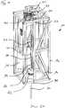
- the underwater drilling apparatus 10comprises a box-shaped base frame 12 which is constructed of steel girders.
- a vertically directed drill guide 24is provided, along which a drill drive 20 is mounted and driven with a clamping device 22 for clamping drill pipe elements 32 vertically movable along a drilling axis 21.
- the drill drive 20is displaceable perpendicular to the drilling axis 21 in a horizontal direction along a transverse rail 23 of the drilling axis 21 away.
- the drill drive 21can serve as part of a feed device 38 to grip in a first storage area 14 of the base frame 12, not shown, mounted drill string elements 32 and to guide them into the drilling axis 21.
- the feed device 38which is indicated only schematically, can have further handling devices in order to grasp, in a known manner, vertically oriented, mounted drill pipe elements 32 and to convey them to the drilling axis 21.
- a new drill pipe element 32is connected to an existing drill pipe element 32 by means of a screw connection.
- Fig. 1only a single drill string elements 32 is shown, which was introduced into the water bottom 5 in a first drilling step.
- a drill head 31 with ground-removing cutting toolsis provided at the lower end.
- a cylindrical core of the upcoming soil materialis formed. This drill core is received in a tubular receptacle 34, which is arranged in the interior of the drill string 30.
- the drilling drive 20For discharging the tubular receptacle 34 with the core arranged and held therein, the drilling drive 20 is first moved out of the drilling axis 21. Subsequently, a hoisting cable 43 of an evacuation device 40 is moved into the area of the drilling axis 21 via a pivoting lever mechanism 41. At the lower free end of the hoist cable 43, a sleeve-shaped locking device 44 is provided. The hoist cable 43 extends from a laterally attached to the base frame 12 Winch 42 via a lower guide roller 45 to an upper deflecting device 46 of the discharge device 40.
- the several times deflected on the frame hoisting rope 43is lowered down, the locking device 44 on the hoisting cable 43 with a connecting device 36 at the upper end of the sleeve-shaped receptacle 34th engages.
- a connectionis made so that the receptacle 34 can be pulled out of the drill pipe 30 with the drill core upwards.
- the sleeve-shaped receptacle 34is conveyed to the core through the discharge device 40 laterally to a second storage area 15 on the base frame 12 and stored therein. Also with regard to the second storage area 15, the magazine-like bearing is not shown in detail for reasons of clarity.
- the sleeve-shaped receptacles 34 with the cores located thereinare stored vertically in brackets, so that the cores can be transported for further investigation together with the underwater drilling apparatus 10 after completion of drilling to a supply ship, not shown.
- an annular sensor device 50is provided concentrically to the drilling axis 21 directly above the borehole opening 18, on which a clamping unit 17 for holding the drill pipe 30 is arranged.
- the sensor device 50is designed with non-contact sensors for determining physical and / or chemical properties of the drill core.
- a data processing device 52is provided, in which the respectively determined data can be stored to a core.
- the position data and in particular the storage location at which the respective core is stored in the second storage area 15can also be stored with the data processing device 52. In the case of a subsequent further analysis of the drill cores, this allows targeted access to the drill cores, which after the first on-site analysis and the data transmitted in advance by the data processing device 52 are of particular interest for a further investigation.
- the discharge device 40is again moved away from the drilling axis 21, so that then the drill drive 20 with a new drill pipe element 32 from the first storage area 14 can be moved back into the drilling axis 21.
- the new drill string member 32may then be connected to the upper drill string member 32 of the drill string 30.
- the drill pipe 30can be drilled again by a drilling step by the length of a drill pipe element 32 in the water bottom 5.
- a new coreis formed, which can be removed according to the method described above from the drill pipe 30 and stored again in the second storage area 15. It can then be done according to further drilling steps, if desired.
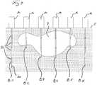
- Fig. 3 1schematically shows the determination of a mineral resource deposit 7 in a water bottom 5 by means of an underwater drilling device 10 according to the invention and a method according to the invention.
- the underwater drilling device 10is first placed on the water bottom 5 to create a first bore 8.1. It then performs a gradual drilling with procurement and investigation of the cores, as previously related to the FIGS. 1 and 2 has been described.
- the first borehole 8.1no data on a mineral resource 7 was found by the underwater boring device 10 according to the invention in the immediate analysis of the cores obtained locally. Accordingly, the first bore 8.1 is performed up to the maximum achievable drilling depth, which is represented by the drill pipe 30 with four drill pipe elements 32 in the present case.
- the underwater drilling apparatus 10can be moved to a second position to perform a second bore 8.2.
- the second drilling step in the creation of the second bore 8.2can be found in the in-situ investigation of the core, that in this hole area the treasure 7 in this depth is over again. Since this can be determined immediately by an evaluation unit, a continuation of the second bore 8.2 can be terminated.
- the underwater drilling device 10can then be set to perform additional holes 8.3, 8.4, 8.5 and 8.6 again.
Landscapes
- Engineering & Computer Science (AREA)
- Life Sciences & Earth Sciences (AREA)
- Geology (AREA)
- Mining & Mineral Resources (AREA)
- Physics & Mathematics (AREA)
- Environmental & Geological Engineering (AREA)
- Fluid Mechanics (AREA)
- General Life Sciences & Earth Sciences (AREA)
- Geochemistry & Mineralogy (AREA)
- Soil Sciences (AREA)
- Remote Sensing (AREA)
- Geophysics (AREA)
- Mechanical Engineering (AREA)
- Earth Drilling (AREA)
- Sampling And Sample Adjustment (AREA)
Description
Translated fromGermanDie Erfindung betrifft eine Unterwasser-Bohrvorrichtung gemäß Anspruch 1.The invention relates to an underwater drilling device according to
Die Erfindung betrifft weiterhin ein Verfahren zum Beschaffen und Analysieren von Bodenproben eines Gewässerbodens, gemäß Anspruch 9.The invention further relates to a method for obtaining and analyzing soil samples of a waterbottom, according to claim 9.
Eine gattungsgemäße Unterwasser-Bohrvorrichtung und ein gattungsgemäßes Verfahren gehen beispielsweise aus der
Für eine Analyse des Gewässerbodenaufbaues ist es bei diesem bekannten Stand der Technik notwendig, die gesamte Bohrvorrichtung von dem Gewässerboden abzuheben und aus dem Gewässer auf ein Versorgungsschiff oder eine Versorgungsplattform zu fördern. Dort können die einzelnen Bohrkerne entnommen, näher untersucht und analysiert werden. Diese Beschaffung und Analyse der Bodenproben ist sehr zeitaufwändig. Insbesondere bei der Durchführung des Verfahrens auf hoher See ist ein hoher Zeitaufwand auch mit sehr hohen Kosten verbunden, da Stunden- oder Tagessätze für Versorgungsschiffe mit dem notwenigen Personal sehr hoch sind. Tagessätze für derartige Versorgungsschiffe können sich auf mehrere 10.000,-EUR bis zu über 100.000,- EUR pro Tag belaufen.For an analysis of the Gewässerbodenaufbaues it is necessary in this prior art to lift the entire drilling device from the water bottom and to promote from the water to a supply ship or supply platform. There, the individual drill cores can be taken, examined more closely and analyzed. This procurement and analysis of the soil samples is very time consuming. In particular, in the implementation of the method on the high seas, a high expenditure of time is associated with very high costs, since hourly or daily rates for supply vessels with the necessary personnel are very high. Daily rates for such supply vessels can amount to several 10,000, -EUR up to over 100,000, - EUR per day.
Aus der
Ein weiteres Verfahren zur Analyse eines Gewässerbodens geht aus der
Bei einem Bohrverfahren an Land ist es bekannt, Bohrkerne unmittelbar an der Bohrstelle zu untersuchen.In a drilling method on land, it is known to investigate cores directly at the drilling site.
Aus der
Der Erfindung liegt dieAufgabe zugrunde, eine Unterwasser-Bohrvorrichtung und ein Verfahren zum Beschaffen und Analysieren von Bodenproben eines Gewässerbodens anzugeben, mit welchem Bodenproben sowohl zuverlässig als auch zeit- und damit kosteneffizient gewonnen und analysiert werden können.The invention has for itsobject to provide an underwater drilling device and a method for obtaining and analyzing soil samples of a waterbed, with which soil samples can be both reliable and time and thus cost-effectively obtained and analyzed.
Die Erfindung wird zum einen durch eine Unterwasser-Bohrvorrichtung mit den Merkmalen des Anspruchs 1 und zum anderen durch ein Verfahren mit den Merkmalen des Anspruchs 9 gelöst. Bevorzugte Ausführungen der Erfindung sind in den jeweils abhängigen Ansprüchen angegeben.The invention is achieved on the one hand by an underwater drilling device with the features of
Die Unterwasser-Bohrvorrichtung ist dadurch gekennzeichnet, dass an dem Grundrahmen in einem Umgebungsbereich der Bohrachse mindestens eine Sensoreinrichtung angeordnet ist, welche zum Ermitteln mindestens einer physikalischen und/oder chemischen Eigenschaft des Bohrkerns ausgebildet ist, und dass eine Datenverarbeitungseinrichtung vorgesehen ist, die zum Speichern von ermittelten Daten zu der mindestens einen physikalischen und/oder chemischen Eigenschaft des Bohrkerns und von Daten zu dem Lagerplatz des Bohrkerns in dem zweiten Lagerbereich ausgebildet ist.The underwater drilling apparatus is characterized in that at least one sensor device, which is designed to determine at least one physical and / or chemical property of the drill core, is arranged on the base frame in a surrounding region of the drilling axis, and in that a data processing device is provided which is capable of storing determined data is formed to the at least one physical and / or chemical property of the core and data to the storage location of the core in the second storage area.
Eine Grundidee der Offenbarung besteht darin, wie bei dem nach dem gattungsbildenden Stand der Technik bekannten Verfahren mit einer Unterwasser-Bohrvorrichtung Bohrkerne während des aufwändigen Kernbohrverfahrens zu gewinnen. Dies so gewonnen Bohrkerne können nach einer Hebung vom Gewässergrund eingehend analysiert werden und können insbesondere bei der Durchführung einer Vielzahl von Probebohrungen an unterschiedlichen Stellen für die Erstellung eines exakten geologischen Profils verwendet werden.A basic idea of the disclosure is to obtain cores during the time-consuming core drilling process as in the underwater drilling apparatus known in the prior art. The cores obtained in this way can be thoroughly analyzed after being lifted from the bottom of the water and can be used in particular for carrying out a large number of test bores at different points for the creation of an exact geological profile.
Dabei besteht ein wesentlicher Aspekt der Offenbarung darin, mit dem Beginn der Analyse der Bohrkerne nicht bis zum Abschluss der Bohrung zu warten. Vielmehr können bereits während des Bohrvorganges beim Abführen des Bohrkernes auf dem Bohrgestänge erste Daten zur Eigenschaft und insbesondere zum Aufbau des Bohrkerns gewonnen werden. Insbesondere bei der Erkundung von Bodenschätzen erlaubt diese erste Analyse von bestimmten Parametern eine Aussage, ob ein weiteres Abbohren an einer Stelle weiterhin sinnvoll ist oder abgebrochen werden sollte. Eine nicht erfolgversprechende Bohrung kann somit frühzeitig festgestellt und beendet werden, was Zeit und Kosten spart.It is an essential aspect of the disclosure, not to wait until the completion of the drilling with the beginning of the analysis of the cores. Rather, it is possible to obtain first data on the property and in particular on the construction of the drill core during the drilling process when the drill core is being removed from the drill string. Especially in the exploration of mineral resources, this first analysis of certain parameters allows a statement as to whether further drilling at one point still makes sense or should be discontinued. An unsuccessful hole can thus be detected and terminated early, which saves time and money.
Zudem können bereits vielversprechende Bohrkerne oder Bohrkerne von besonderem Interesse noch während des Bohrvorganges ermittelt werden. Nach einem Heben der Unterwasser-Bohrvorrichtung mit den Bohrkernen können dann gezielt diese Bohrkerne von besonderem Interesse zuerst untersucht und analysiert werden. Hieraus können schneller Rückschlüsse über Ort oder Art und Weise einer weiteren Probebohrung getroffen werden.In addition, promising drill cores or cores of particular interest can still be determined during the drilling process. After lifting the underwater drilling rig with the cores can then specifically this Core cores of special interest should first be investigated and analyzed. From this, conclusions can be drawn more quickly about the location or type of further test drilling.
Dabei besteht eine bevorzugte Ausführungsform darin, dass eine Datenübertragungseinrichtung vorgesehen ist, mit welcher die ermittelten Daten zu einer beabstandeten Zentrale übertragbar sind. Mittels der Datenübertragungseinrichtung kann die Datenübertragung drahtlos oder drahtgebunden erfolgen. Dies erlaubt eine vorzeitige Analyse von Bohrkernen etwa auf dem Versorgungsschiff oder einer entfernt liegenden Zentrale, noch während die Probebohrung weiter durchgeführt wird.In this case, a preferred embodiment is that a data transmission device is provided, with which the determined data can be transmitted to a remote center. By means of the data transmission device, the data transmission can be wireless or wired. This allows for early analysis of cores on, for example, the supply ship or a remote center while the test well continues to run.
Eine besonders effiziente Verfahrensdurchführung wird gemäß einer Weiterbildung der Unterwasser-Bohrvorrichtung dadurch erreicht, dass die Datenverarbeitungseinrichtung eine Auswerteeinheit aufweist, in welcher Entscheidungskriterien gespeichert sind und welche ausgelegt ist, basierend auf den gespeicherten Entscheidungskriterien eine Entscheidung über einen Fortgang oder einen Abbruch der Bohrung zu treffen. Als Entscheidungskriterien können insbesondere Mindest- oder Maximalwerte für bestimmte physikalische oder chemische Größen vorgesehen sein, welche für eine Entscheidung über einen Fortgang oder einen Abbruch der Bohrung von besonderer Bedeutung sind. So kann etwa eine Aussage zur elektrischen Leitfähigkeit oder zum Induktionsverhalten des Bohrkernes darauf hinweisen, dass etwa spezielle metallische Bodenschätze vorliegen oder nicht vorliegen. Diese Entscheidungskriterien können durch im Voraus durchgeführte Testverfahren oder auch durch empirische Ergebnisse vorausgegangener Bohrungen festgesetzt werden. Die Entscheidungskriterien hängen maßgeblich von der jeweiligen Art der Bodenschätze ab, nach welchen gezielt gesucht wird. Werden beispielsweise bestimmte Kennwerte bei einer bestimmten Bohrtiefe nicht erreicht, so kann es wirtschaftlich sinnvoll sein, das weitere Bohren an dieser Untersuchungsstelle abzubrechen und an einer anderen Stelle fortzusetzen. Es kann auch ein Vergleich mit den Messwerten des oder der vorausgegangenen Bohrkerne in der Datenverarbeitungseinrichtung erfolgen. Es kann so etwa festgestellt werden, ob man sich einem Vorkommen eines bestimmten Bodenschatzes, etwa von Massivsulfid, Erzen oder Öl, nähert oder sich hiervon entfernt.A particularly efficient method implementation is achieved in accordance with a further development of the underwater drilling apparatus in that the data processing unit has an evaluation unit in which decision criteria are stored and which is designed to make a decision based on the stored decision criteria about a progress or termination of the hole. Minimum or maximum values for particular physical or chemical quantities, which are of particular importance for a decision on the progress or termination of the well, may be provided as decision criteria. For example, a statement about the electrical conductivity or the induction behavior of the drill core may indicate that special metallic minerals are present or not present. These decision criteria can be determined by pre-testing or empirical results from previous drilling. The decision criteria depend to a large extent on the respective type of mineral resources, which are searched for purposefully. If, for example, certain characteristic values are not reached at a certain drilling depth, it may be economically sensible to stop further drilling at this examination site and to continue at another location. A comparison can also be made with the measured values of the previous drill core (s) in the data processing device. It can thus be determined, for example, whether one is approaching or moving away from a deposit of a particular mineral, such as massive sulphide, ore or oil.
Aufgrund dieser Ausbildung muss etwa in diesem Fall die Bohrvorrichtung nicht mehr für eine Analyse der Bohrkerne aus dem Gewässer geborgen werden. Vielmehr kann die Unterwasser-Bohrvorrichtung im Gewässer verbleiben und mit dem Versorgungsschiff an eine andere Stelle gesetzt werden. Grundsätzlich kann die Sensoreinrichtung in beliebiger Art und Weise ausgebildet und angeordnet sein. Gemäß einer vorteilhaften Ausgestaltung ist es vorgesehen, dass die mindestens eine Sensoreinrichtung ringförmig und im Bereich oberhalb der Bohrlochöffnung angeordnet ist. Die Bohrlochöffnung kann dabei ein Bohrlochverschluss oder eine sonstige Anordnung zur Stabilisierung der Öffnung am Bohrloch sein. Über eine ringförmige Anordnung der Sensoreinrichtung kann eine umfassende und vorzugsweise berührungsfreie Erfassung des Bohrkernes unmittelbar bei Austritt aus dem Bohrloch erfolgen. Dabei kann die Sensoreinrichtung so ausgestaltet sein, dass eine Ermittlung berührungslos auch durch die Wandung der rohrförmigen Aufnahme erfolgt, etwa durch eine Wechselwirkung mit einem magnetischen oder elektromagnetischen Feld. So kann etwa ein erhöhter oder verringerter Anteil von Erdöl in einem Gestein dessen elektromagnetisches Resonanzverhalten und dessen Leitfähigkeit merklich verändern.Due to this training, the drilling device no longer needs to be recovered for analysis of the cores from the water, for example in this case. Rather, the underwater drilling device can remain in the water and be placed with the supply ship to another location. In principle, the sensor device can be designed and arranged in any desired manner. According to an advantageous embodiment, it is provided that the at least one sensor device is arranged annularly and in the region above the borehole opening. The well bore may be a downhole closure or other arrangement for stabilizing the well bore opening. By means of an annular arrangement of the sensor device, comprehensive and preferably non-contact detection of the drill core can take place immediately upon exiting the borehole. In this case, the sensor device can be configured so that a determination is also made without contact by the wall of the tubular receptacle, for example by an interaction with a magnetic or electromagnetic field. For example, an increased or decreased proportion of petroleum in a rock can significantly alter its electromagnetic resonance behavior and its conductivity.
Grundsätzlich kann je nach der vorgesehenen Suche nach bestimmten Bodenschätzen eine geeignete Sensoreinrichtung ausgewählt werden. Es können auch optische Sensoren oder Sensoren zur Messung der Radioaktivität vorgesehen sein. Nach einer bevorzugten Ausführungsvariante der Erfindung ist vorgesehen, dass die Sensoreinrichtung zur Messung einer Induktivität, elektrischen Leitfähigkeit, einer Kapazität und/oder weiterer physikalischer oder chemischer Größen ausgebildet ist. Insbesondere können in einem ringförmigen Gehäuse auch verschiedene Arten von Sensoren vorgesehen sein, so dass gleichzeitig eine Überprüfung und Analyse nach verschiedenen Kenngrößen erfolgen kann.In principle, depending on the intended search for specific mineral resources, a suitable sensor device can be selected. It may also be provided optical sensors or sensors for measuring the radioactivity. According to a preferred embodiment of the invention, it is provided that the sensor device is designed to measure an inductance, electrical conductivity, a capacitance and / or further physical or chemical variables. In particular, various types of sensors can be provided in an annular housing, so that at the same time a review and analysis can be carried out according to different characteristics.
Weiterhin ist es nach einer Ausführungsform vorteilhaft, dass die Aufnahme rohrförmig als ein Kernrohrfänger ausgebildet ist, welcher an seinem oberen Ende eine Verbindungseinrichtung für die Abführeinrichtung aufweist. Der Kernrohrfänger kann dabei insbesondere als ein dünnwandiges Rohr aus einem Metall oder einem Kunststoff gebildet sein, in welchem sich beim Abbohren des rohrförmigen Bohrgestänges ein innerer verbleibender Bodenbereich als Bohrkern in einen Aufnahmeraum des Kernrohrfängers hineinschiebt. Durch eine entsprechende Verschlussvorrichtung oder sonstige Halteeinrichtungen kann der Bohrkern in der rohrförmigen Aufnahme fixiert werden. Nachdem ein weiterer Bohrschritt entsprechend der Länge eines Bohrgestängeelementes erfolgt ist, kann die Aufnahme mit dem darin eingeschlossenen Bohrkern über die Abführeinrichtung aus dem Bohrgestänge gezogen und zu dem zweiten Lagerbereich gefördert werden, wobei die Aufnahme mit dem Bohrkern an einem bestimmten vorgesehenen Lagerplatz des zweiten Lagerbereiches abgesetzt wird. Nach dem Absetzen kann die Abführeinrichtung von der Aufnahme gelöst werden, so dass nach einem weiteren Bohrschritt eine weitere Aufnahme mit einem Bohrkern abgeführt werden kann.Furthermore, according to one embodiment, it is advantageous for the receptacle to be tubular in shape as a core pipe catcher, which has a connecting device for the removal device at its upper end. The core pipe catcher can be formed in particular as a thin-walled pipe made of a metal or a plastic, in which when drilling the tubular drill string an inner remaining soil area as a core in a receiving space of the core pipe catcher. By a corresponding closure device or other holding devices, the core can be fixed in the tubular receptacle. After a further drilling step has taken place corresponding to the length of a drill string element, the receptacle with the drill core enclosed therein can be pulled out of the drill pipe via the discharge device and conveyed to the second storage area, wherein the receptacle with the drill core is deposited at a specific intended storage location of the second storage area becomes. After settling, the discharge device can be released from the receptacle, so that after a further drilling step, a further receptacle can be removed with a drill core.
Dabei ist es nach einer Weiterbildung zweckmäßig, dass die Abführeinrichtung eine Winde mit einem Hubseil aufweist, an dessen freien Ende eine Verriegelungseinrichtung angeordnet ist, welche mit einer Verbindungseinrichtung an der Aufnahme für den Bohrkern zusammenwirkt. Die Verriegelungseinrichtung kann dabei insbesondere eine Hakenanordnung sein, welche in eine etwa als Öse ausgebildete Verbindungseinrichtung an der rohrförmigen Aufnahme eingreift. Auf diese Weise kann eine formschlüssige Verbindung zum Abführen der Aufnahme mit dem Bohrkern gebildet werden. Es sind aber auch andere Verbindungsmethoden denkbar, etwa eine elektromagnetische Verbindung durch eine Anordnung entsprechender Elektromagnete.It is expedient according to a development that the discharge device comprises a winch with a hoist rope, at the free end of a locking device is arranged, which cooperates with a connecting device on the receptacle for the core. The locking device may in particular be a hook arrangement, which engages in an approximately formed as an eyelet connection means on the tubular receptacle. In this way, a positive connection for discharging the recording with the core can be formed. But there are also other connection methods conceivable, such as an electromagnetic connection by an arrangement of corresponding electromagnets.
Eine weitere bevorzugte Ausführungsvariante besteht darin, dass der Grundrahmen über eine maritime Nabelschnur mit einem Versorgungsschiff verbunden ist. Die maritime Nabelschnur kann dabei sowohl zur Versorgung mit Energie, insbesondere elektrischer Energie und Hydraulikflüssigkeit, sowie als eine Datenleitung zur Datenkommunikation vorgesehen sein. Weiterhin kann die maritime Nabelschnur auch als ein Hubseil ausgebildet sein, mit welcher neben der Versorgungsfunktion die Unterwasser-Bohrvorrichtung abgesenkt und wieder gehoben werden kann.Another preferred embodiment is that the base frame is connected via a maritime umbilical cord to a supply ship. The maritime umbilical cord can be provided both for the supply of energy, in particular electrical energy and hydraulic fluid, as well as a data line for data communication. Furthermore, the maritime umbilical cord can also be designed as a hoisting rope with which, in addition to the supply function, the underwater drilling device can be lowered and lifted again.
Die eingangs angeführte Aufgabe wird hinsichtlich des Verfahrens dadurch gelöst, dass mittels mindestens einer Sensoreinrichtung, welche an dem Grundrahmen in einem Umgebungsbereich der Bohrachse angeordnet ist, mindestens eine physikalische und/oder chemische Eigenschaft des Bohrkernes ermittelt wird, und dass die dabei ermittelten Daten in einer Datenverarbeitungseinrichtung zusammen mit den Daten zu dem Lagerplatz des Bohrkernes in dem zweiten Lagerbereich abgespeichert werden. Das Verfahren kann insbesondere mit der zuvor beschriebenen Unterwasser-Bohrvorrichtung ausgeführt werden.With regard to the method, the object stated at the outset is achieved by virtue of at least one physical and / or chemical property of the drill core by means of at least one sensor device which is arranged on the base frame in a surrounding region of the drilling axis is determined, and that the data determined thereby are stored in a data processing device together with the data to the storage location of the core in the second storage area. The method can be carried out in particular with the underwater drilling device described above.
Es ergeben sich die zuvor beschriebenen Vorteile bei der Durchführung des Verfahrens.This results in the advantages described above in carrying out the method.
Eine bevorzugte Verfahrensvariante besteht darin, dass basierend auf den ermittelten Daten zu der mindestens einen physikalischen und/oder chemischen Eigenschaft des Bohrkernes eine Entscheidung über einen Fortgang oder einen Abbruch der Bohrung getroffen wird, während die Bohrvorrichtung sich weiterhin in dem Gewässer auf dem Gewässerboden befinden. Diese Entscheidung dann dabei vorzugsweise durch die Unterwasser-Bohrvorrichtung selbst durch eine Auswerteeinheit in der Datenverarbeitungseinrichtung getroffen werden oder durch Datenfernübertragung von einer beabstandeten Zentrale, etwa auf dem Versorgungsschiff oder einer Station an Land.A preferred variant of the method is that, based on the determined data on the at least one physical and / or chemical property of the drill core, a decision is made on progress or termination of the drill hole while the drilling device continues to be located in the body of water on the water bed. This decision then preferably be made by the underwater drilling device itself by an evaluation in the data processing device or by remote data transmission from a remote center, such as on the supply ship or a station on land.
Auf diese Weise können Fehlbohrungen frühzeitig erkannt und die Unterwasser-Bohrvorrichtung zeit- und kosteneffizient eingesetzt werden.In this way, bad holes can be detected early and used the underwater drilling device time and cost efficient.
Die Erfindung wird nachfolgend anhand von bevorzugten Ausführungsbeispielen weiter erläutert, welche schematisch in den beigefügten Zeichnungen dargestellt sind. In den Zeichnungen zeigen:
- Fig. 1
- eine schematische perspektivische Ansicht einer Unterwasser-Bohrvorrichtung nach der Erfindung;
- Fig. 2
- eine schematische Seitenansicht der Unterwasser-Bohrvorrichtung nach
Fig. 1 ; und - Fig. 3
- eine schematische Darstellung mit einer Vielzahl von Probebohrungen.
- Fig. 1
- a schematic perspective view of an underwater drilling apparatus according to the invention;
- Fig. 2
- a schematic side view of the underwater drilling device according to
Fig. 1 ; and - Fig. 3
- a schematic representation with a large number of test bores.
Der Aufbau und die Funktion einer Unterwasser-Bohrvorrichtung 10 werden im Zusammenhang mit den
Zum Bilden eines Bohrgestänges 30 wird ein neues Bohrgestängeelement 32 an ein bereits vorhandenes Bohrgestängeelement 32 mittels Schraubverbindung angeschlossen. In
Zum Abführen der rohrförmigen Aufnahme 34 mit dem darin angeordneten und gehaltenen Bohrkern wird der Bohrantrieb 20 zunächst aus der Bohrachse 21 herausgefahren. Anschließend wird über einen Schwenkhebelmechanismus 41 ein Hubseil 43 einer Abführeinrichtung 40 in den Bereich der Bohrachse 21 bewegt. Am unteren freien Ende des Hubseiles 43 ist eine hülsenförmige Verriegelungseinrichtung 44 vorgesehen. Das Hubseil 43 verläuft von einer am Grundrahmen 12 seitlich befestigten Winde 42 über eine untere Anlenkrolle 45 zu einer oberen Umlenkeinrichtung 46 der Abführeinrichtung 40. Über die Winde 42 wird das mehrfach am Rahmen umgelenkte Hubseil 43 nach unten abgelassen, wobei die Verriegelungseinrichtung 44 am Hubseil 43 mit einer Verbindungseinrichtung 36 am oberen Ende der hülsenförmigen Aufnahme 34 in Eingriff kommt. Dabei wird eine Verbindung hergestellt, so dass die Aufnahme 34 mit dem Bohrkern nach oben aus dem Bohrgestänge 30 herausgezogen werden kann. Anschließend wird die hülsenförmige Aufnahme 34 mit dem Bohrkern über die Abführeinrichtung 40 seitlich zu einem zweiten Lagerbereich 15 an dem Grundrahmen 12 gefördert und darin abgelegt. Auch hinsichtlich des zweiten Lagerbereiches 15 ist das magazinähnliche Lager aus Übersichtlichkeitsgründen nicht näher dargestellt. In dem zweiten Lagerbereich 15 werden die hülsenförmigen Aufnahmen 34 mit den darin befindlichen Bohrkernen vertikal in Halterungen gelagert, so dass die Bohrkerne zur weiteren Untersuchung zusammen mit der Unterwasser-Bohrvorrichtung 10 nach Abschluss der Bohrarbeiten zu einem nicht dargestellten Versorgungsschiff befördert werden können.For discharging the
Für eine vorausgehende Untersuchung und Analyse der Bohrkerne ist unmittelbar oberhalb der Bohrlochöffnung 18, an welcher eine Spanneinheit 17 zum Halten des Bohrgestänges 30 angeordnet ist, konzentrisch zur Bohrachse 21 eine ringförmige Sensoreinrichtung 50 vorgesehen. Die Sensorvorrichtung 50 ist mit berührungslos arbeitenden Sensoren zur Bestimmung physikalischer und/oder chemischer Eigenschaften des Bohrkernes ausgebildet. Weiterhin ist eine Datenverarbeitungseinrichtung 52 vorgesehen, in welcher die jeweils ermittelten Daten zu einem Bohrkern abgespeichert werden können. Gleichzeitig können mit der Datenverarbeitungseinrichtung 52 auch die Positionsdaten und insbesondere der Lagerplatz gespeichert werden, an welchem der jeweilige Bohrkern im zweiten Lagerbereich 15 abgelegt wird. Dies erlaubt bei einer späteren weiteren Analyse der Bohrkerne gezielt auf die Bohrkerne zurückzugreifen, welche nach der ersten Vorortanalyse und den vorab von der Datenverarbeitungseinrichtung 52 übermittelten Daten von besonderem Interesse für eine weitere Untersuchung sind.For a preliminary examination and analysis of the drill cores, an
Nach diesem ersten Bohrschritt mit Sicherung eines Bohrkernes wird die Abführvorrichtung 40 wieder aus der Bohrachse 21 fortbewegt, so dass anschließend der Bohrantrieb 20 mit einem neuen Bohrgestängeelement 32 aus dem ersten Lagerbereich 14 wieder in die Bohrachse 21 bewegt werden kann. Das neue Bohrgestängeelement 32 kann sodann an das obere Bohrgestängeelement 32 des Bohrgestänges 30 angeschlossen werden. Abschließend kann dann das Bohrgestänge 30 wieder um einen Bohrschritt um die Länge eines Bohrgestängeelementes 32 in den Gewässerboden 5 abgebohrt werden. Dabei wird ein neuer Bohrkern gebildet, welcher entsprechend dem voraus beschriebenen Verfahren aus dem Bohrgestänge 30 entfernt und wieder in dem zweiten Lagerbereich 15 abgelegt werden kann. Es können dann entsprechend weitere Bohrschritte erfolgen, soweit dies gewünscht wird.After this first drilling step with securing a core, the
In
Die Unterwasser-Bohrvorrichtung 10 wird zunächst zum Erstellen einer ersten Bohrung 8.1 auf den Gewässerboden 5 aufgesetzt. Es erfolgt dann ein schrittweises Abbohren mit Beschaffung und Untersuchung der Bohrkerne, wie es zuvor im Zusammenhang mit den
Nach Rückbau des Bohrgestänges 30 kann die Unterwasser-Bohrvorrichtung 10 zu einer zweiten Position versetzt werden, um eine zweite Bohrung 8.2 durchzuführen. Im dargestellten Ausführungsbeispiel ergibt sich bereits nach dem ersten Bohrschritt durch die Sensoreinrichtung 50 das Vorhandensein eines Bodenschatzvorkommens 7. Nach dem zweiten Bohrschritt bei der Erstellung der zweiten Bohrung 8.2 kann bei der Insitu-Untersuchung des Bohrkernes festgestellt werden, dass bei diesem Bohrungsbereich das Bodenschatzvorkommen 7 in dieser Tiefenlage wieder beendet ist. Da dies umgehend von einer Auswerteeinheit festgestellt werden kann, kann ein Fortgang der zweiten Bohrung 8.2 beendet werden. Die Unterwasser-Bohrvorrichtung 10 kann dann zur Durchführung weiterer Bohrungen 8.3, 8.4, 8.5 und 8.6 wieder versetzt werden.After disassembly of the
Dem Ausführungsbeispiel nach
Claims (10)
- Underwater drilling device (10) for procuring and analyzing ground samples of a bed of a body of water, having- a base frame (12) which is designed for lowering into a body of water and for placing onto the bed of the body of water (5),- a drill drive (20) for rotationally driving a drill rod (30) which is composed of tubular drill rod elements (32), wherein the drill drive (20) is supported in a vertically movable manner along a drilling axis (21) between a lower borehole opening (18) and an upper retracted position,- a first storage area (14) on the base frame (12) for storing the individual tubular drill rod elements (32) for assembly of the drill rod (30), wherein a receiving part (34) for a drill core is in each case held in a releasable manner in the drill rod elements (32),- a second storage area (15) on the base frame (12) for storing the receiving parts (34) with the obtained drill cores as a ground sample,- a supply means (38), with which individual drill rod elements (32) can be supplied from the first storage area (14) to the drilling axis (21) in order to form the drill rod (30), and- a removal means (40) for removing a receiving part (34) with drill core from the drill rod (30) and for depositing in a specific storage place in the second storage area (15),
characterized in that- on the base frame (12) in a surrounding area of the drilling axis (21) at least one sensor means (50) is arranged, which is designed for determining at least one physical and/or chemical property of the drill core, and-in that a data processing means (52) is provided, which is designed for storing data determined on the at least one physical and/or chemical property of the drill core and data on the storage place of the drill core in the second storage area (15). - Underwater drilling device according to claim 1,
characterized in that
a data transmission unit is provided, with which the determined data can be transmitted to a central facility located at a distance. - Underwater drilling device according to claim 1 or 2,
characterized in that
the data processing means (52) has an evaluation unit, in which decision criteria are stored and which is configured to make a decision on a continuation or discontinuation of drilling on the basis of the stored decision criteria. - Underwater drilling device according to any one of claims 1 to 3,
characterized in that
the at least one sensor means (50) is annular and arranged in the area above the borehole opening (18). - Underwater drilling device according to any one of claims 1 to 4,
characterized in that
the sensor means (50) is designed for measuring an inductance, electrical conductivity, a capacity and/or further physical or chemical quantities. - Underwater drilling device according to any one of claims 1 to 5,
characterized in that
the receiving part (34) is designed in a tubular manner as a core tube catcher, which has at its upper end a connecting means (36) for the removal means (40). - Underwater drilling device according to any one of claims 1 to 6,
characterized in that
the removal means (40) has a winch (42) with a hoist rope (43), at the free end of which a locking means (44) is arranged which interacts with a connecting means (36) on the receiving part (34) for the drill core. - Underwater drilling device according to any one of claims 1 to 7,
characterized in that
the base frame (12) is connected via a maritime umbilical to a supply vessel. - Method for procuring and analyzing ground samples of a bed of a body of water, in particular with an underwater drilling device (10) according to any one of claims 1 to 8, in which- an underwater drilling device (10) with a base frame (12) is lowered into a body of water and placed onto a bed of the body of water (5),- having a drill drive (20) which is supported in a vertically movable manner on the base frame (12), a drill rod (30) composed of at least one tubular drill rod element (32) is drilled into the bed of the body of water (5) in a first drilling step, wherein a drill core is formed and received in a receiving part (34) in the tubular drill rod element (32),- the receiving part (34) with the drill core is removed by means of a removal means (40) from the drill rod (30) and deposited in a storage place of a second storage area (15) on the base frame (12) and- subsequently at least one further drilling step is carried out, wherein by means of a supply means (38) a further drill rod element (32) with a receiving part (34) for a drill core is supplied from a first storage area (14) to the drill rod (30) and a further drilling of the drill rod (30) is effected with the drill drive (20),
characterized in that- by means of at least one sensor means (50) at least one physical and/or chemical property of the drill core is determined and-in that the data thereby determined are stored in a data processing means (52) together with the data on the storage place of the drill core in the second storage area (15). - Method according to claim 9,
characterized in that
on the basis of the data determined on the at least one physical and/or chemical property of the drill core a decision is made on a continuation or discontinuation of drilling while the underwater drilling device (10) is still located in the body of water on the bed of the body of water (5).
Applications Claiming Priority (1)
| Application Number | Priority Date | Filing Date | Title |
|---|---|---|---|
| PCT/EP2014/059760WO2015172818A1 (en) | 2014-05-13 | 2014-05-13 | Underwater drilling device and method for obtaining and analysing soil samples of the bed of a body of water |
Publications (2)
| Publication Number | Publication Date |
|---|---|
| EP3117068A1 EP3117068A1 (en) | 2017-01-18 |
| EP3117068B1true EP3117068B1 (en) | 2019-03-06 |
Family
ID=50928056
Family Applications (1)
| Application Number | Title | Priority Date | Filing Date |
|---|---|---|---|
| EP14729223.9AActiveEP3117068B1 (en) | 2014-05-13 | 2014-05-13 | Underwater drilling device and method for obtaining and analysing soil samples of the bed of a body of water |
Country Status (7)
| Country | Link |
|---|---|
| US (1) | US9909377B2 (en) |
| EP (1) | EP3117068B1 (en) |
| JP (1) | JP6307177B2 (en) |
| CN (1) | CN106661932B (en) |
| CA (1) | CA2944062C (en) |
| ES (1) | ES2729345T3 (en) |
| WO (1) | WO2015172818A1 (en) |
Families Citing this family (9)
| Publication number | Priority date | Publication date | Assignee | Title |
|---|---|---|---|---|
| JP6813990B2 (en)* | 2016-08-24 | 2021-01-13 | 古河機械金属株式会社 | Submarine deposit mining and exploration methods, as well as submarine deposit mining and exploration bases, submarine deposit exploration equipment and fluorescent X-ray analyzers |
| WO2019010572A1 (en)* | 2017-07-11 | 2019-01-17 | Les Équipements De Forage Versadrill Inc. | Core tube displacer for long reach drilling machines |
| CN107965317B (en)* | 2017-12-14 | 2023-04-14 | 中国科学院海洋研究所 | A kind of ROV-based sampler and sampling method of omnidirectional underwater short-distance drilling rig |
| US11512535B2 (en)* | 2018-05-24 | 2022-11-29 | Benthic Usa Llc | Dual rotary elevating geotechnical drill |
| CN113242929A (en) | 2018-12-20 | 2021-08-10 | 包尔机械有限公司 | Underwater drilling apparatus and method for obtaining a drilling core from the bottom of a body of water |
| ES2888924A1 (en)* | 2020-06-29 | 2022-01-10 | Geociencias Y Exploraciones Marinas S L | Machine and procedure for underwater soundings (Machine-translation by Google Translate, not legally binding) |
| CN113295453B (en)* | 2021-04-27 | 2022-11-11 | 中交华南勘察测绘科技有限公司 | Soil sampling device and sampling method |
| CN113605851B (en)* | 2021-08-27 | 2023-03-10 | 山东省地质矿产勘查开发局第一地质大队(山东省第一地质矿产勘查院) | Rope core-taking off-axis anti-inclination drilling tool |
| EP4556678B1 (en) | 2023-11-14 | 2025-09-03 | BAUER Maschinen GmbH | Underwater drilling device and method for probing a bed of a body of water |
Family Cites Families (28)
| Publication number | Priority date | Publication date | Assignee | Title |
|---|---|---|---|---|
| DE2309974C3 (en)* | 1973-02-28 | 1981-10-08 | Kernforschungszentrum Karlsruhe Gmbh, 7500 Karlsruhe | Device for geophysical in-situ analysis of ore concretions |
| US4043404A (en) | 1976-01-15 | 1977-08-23 | Deere & Company | Tillage apparatus having improved cutting and drive structure |
| GB2094852B (en)* | 1981-03-09 | 1985-06-26 | Jonell Per Olof | Submarine core drilling unit |
| JPH06100051B2 (en)* | 1985-02-04 | 1994-12-12 | 日鉱金属株式会社 | Automatic drilling method |
| JP3108892B2 (en)* | 1992-04-24 | 2000-11-13 | 鉱研工業株式会社 | Rod feeder |
| US5453693A (en) | 1993-10-01 | 1995-09-26 | Halliburton Company | Logging system for measuring dielectric properties of fluids in a cased well using multiple mini-wave guides |
| BE1008302A3 (en) | 1994-05-30 | 1996-04-02 | Baroid Technology Inc | Method and device for detection or and / or measuring at least one parameter geophysical on a carrot. |
| JP3205697B2 (en)* | 1995-11-15 | 2001-09-04 | 飛島建設株式会社 | AE generation position measuring device |
| JPH09243607A (en) | 1996-03-07 | 1997-09-19 | Hitachi Eng & Services Co Ltd | Wire bundle waveguide rod for observing underground sound and measurement of underground sound |
| AUPO857197A0 (en)* | 1997-08-15 | 1997-09-04 | Benthic Geotech Pty Ltd | Improved methods for seabed piston coring |
| GB9909364D0 (en)* | 1999-04-23 | 1999-06-16 | Xl Technology Limited | Seabed analysis |
| US6822579B2 (en) | 2001-05-09 | 2004-11-23 | Schlumberger Technology Corporation | Steerable transceiver unit for downhole data acquistion in a formation |
| US6672407B2 (en)* | 2001-09-20 | 2004-01-06 | Halliburton Energy Services, Inc. | Method of drilling, analyzing and stabilizing a terrestrial or other planetary subsurface formation |
| CN1249325C (en)* | 2002-02-06 | 2006-04-05 | 国家海洋局第一海洋研究所 | Deep-sea multile-bit incrusting and coring rig |
| JP2006083552A (en)* | 2004-09-14 | 2006-03-30 | Koken Boring Mach Co Ltd | Submarine boring machine |
| JP5004200B2 (en) | 2005-06-23 | 2012-08-22 | 学校法人金沢工業大学 | SQUID sensor dewar and SQUID sensor |
| US8122965B2 (en)* | 2006-12-08 | 2012-02-28 | Horton Wison Deepwater, Inc. | Methods for development of an offshore oil and gas field |
| US7380614B1 (en) | 2007-05-11 | 2008-06-03 | Williamson & Associates, Inc. | Remotely operated water bottom based drilling system using cable for auxiliary operations |
| US20090107724A1 (en)* | 2007-10-24 | 2009-04-30 | Schlumberger Technology Corporation | Method and apparatus for continuous formation sampling and analysis during wellbore drilling |
| US20090178847A1 (en)* | 2008-01-10 | 2009-07-16 | Perry Slingsby Systems, Inc. | Method and Device for Subsea Wire Line Drilling |
| WO2009117347A1 (en)* | 2008-03-17 | 2009-09-24 | Pardey Harold M | Detachable latch head for core drilling |
| JP5666795B2 (en)* | 2009-09-28 | 2015-02-12 | 株式会社ワイビーエム | Ground construction machine and its tool drive control method |
| JP5580103B2 (en)* | 2010-04-15 | 2014-08-27 | 三井造船株式会社 | Submarine boring machine |
| WO2012000077A1 (en) | 2010-06-30 | 2012-01-05 | Marl Technologies Inc. | Remotely operable underwater drilling system and drilling method |
| JP5912613B2 (en)* | 2012-02-07 | 2016-04-27 | 株式会社竹中工務店 | Excavation hole excavation accuracy measuring device and excavation hole excavation accuracy measuring method |
| KR20150031412A (en) | 2012-06-22 | 2015-03-24 | 노틸러스 미네랄즈 퍼시픽 피티 리미티드 | An apparatus, system and method for actuating downhole tools in subsea drilling operations |
| US20150176404A1 (en)* | 2012-07-27 | 2015-06-25 | Nautilus Minerals Pacific Pty Ltd | Apparatus and Method for Subsea Testing |
| EP2860341A1 (en)* | 2013-10-10 | 2015-04-15 | Soil Machine Dynamics Limited | Subsea support apparatus for supporting drive means, and driving apparatus incorporating such support apparatus |
- 2014
- 2014-05-13EPEP14729223.9Apatent/EP3117068B1/enactiveActive
- 2014-05-13WOPCT/EP2014/059760patent/WO2015172818A1/enactiveApplication Filing
- 2014-05-13CACA2944062Apatent/CA2944062C/enactiveActive
- 2014-05-13ESES14729223Tpatent/ES2729345T3/enactiveActive
- 2014-05-13JPJP2016562941Apatent/JP6307177B2/ennot_activeExpired - Fee Related
- 2014-05-13USUS15/309,912patent/US9909377B2/ennot_activeExpired - Fee Related
- 2014-05-13CNCN201480078654.4Apatent/CN106661932B/enactiveActive
Non-Patent Citations (1)
| Title |
|---|
| None* |
Also Published As
| Publication number | Publication date |
|---|---|
| CN106661932A (en) | 2017-05-10 |
| CA2944062A1 (en) | 2015-11-19 |
| CA2944062C (en) | 2018-11-06 |
| CN106661932B (en) | 2020-12-22 |
| US9909377B2 (en) | 2018-03-06 |
| JP6307177B2 (en) | 2018-04-04 |
| US20170152719A1 (en) | 2017-06-01 |
| WO2015172818A1 (en) | 2015-11-19 |
| JP2017519130A (en) | 2017-07-13 |
| ES2729345T3 (en) | 2019-10-31 |
| EP3117068A1 (en) | 2017-01-18 |
Similar Documents
| Publication | Publication Date | Title |
|---|---|---|
| EP3117068B1 (en) | Underwater drilling device and method for obtaining and analysing soil samples of the bed of a body of water | |
| DE69111609T2 (en) | METHOD AND DEVICE FOR TAKING AND ANALYZING PORE GAS / PORE LIQUID SAMPLES FROM UNDERGROUND FORMATIONS OF A SPECIFIC DEPTH. | |
| DE2540590A1 (en) | METHOD AND DEVICE FOR MAKING A BORE UNDER AN OBSTACLE ALONG AN ARC-SHAPED TRACK | |
| DE102018006901B4 (en) | Device and method for carrying out geological investigations | |
| DE102005030559A1 (en) | Apparatus and method for characterizing a subterranean formation and apparatus and method for perforating a cased borehole | |
| DE2747748A1 (en) | METHOD FOR DETERMINING MEASURED VALUES OF THE FORMATIONS SURROUNDING A DEEP HOLE | |
| DE3886904T2 (en) | Method and device for the safe handling of radioactive sources in tools for borehole measurements during drilling. | |
| EP3124740B1 (en) | Drilling apparatus and method for producing a borehole from a floating platform | |
| EP0158001A1 (en) | Gauge for determining the profile of boreholes in rock | |
| DE4200426A1 (en) | Compartmented grooved rod soil sample removal unit with tubular casing - has filling slot and cutting edge moving against each other with control resulting across follower and stop ring. | |
| DE3879045T2 (en) | SOIL SAMPLER. | |
| EP2698499B1 (en) | Method and device producing and measuring a borehole | |
| EP4556678B1 (en) | Underwater drilling device and method for probing a bed of a body of water | |
| EP1527234B1 (en) | Method and device for soil analysis | |
| DE1946647A1 (en) | Method and device for determining the bearing capacity of subterranean formations | |
| DE3125239A1 (en) | Soil sampling device and method for collecting an undisturbed soil sample | |
| DE19534696A1 (en) | Introducing measuring instruments into horizontal or sloping borehole | |
| DE3515983A1 (en) | SYSTEM FOR DETERMINING THE FREE POINT OF A DRILLING PIPE FIXED IN A HOLE HOLE | |
| DE3400833C1 (en) | Stationary measuring device for determining the change in the diameter of rock drill holes | |
| DE2418691C3 (en) | Downhole equipment | |
| DE2807551C2 (en) | Device and method for the geophysical investigation of underground caverns and for taking samples from fluid-filled caverns | |
| DE2631642C3 (en) | Procedure for creating a small well | |
| DE102011052695B4 (en) | Process and bead tube for the treatment of boreholes | |
| DE534563C (en) | Method for identifying the soil layers penetrated by deep boreholes by means of electrical resistance measurement | |
| DE19940572A1 (en) | Ground sampling method uses freezing lance takes sample from bottom of prebore avoids distortion. |
Legal Events
| Date | Code | Title | Description |
|---|---|---|---|
| PUAI | Public reference made under article 153(3) epc to a published international application that has entered the european phase | Free format text:ORIGINAL CODE: 0009012 | |
| STAA | Information on the status of an ep patent application or granted ep patent | Free format text:STATUS: REQUEST FOR EXAMINATION WAS MADE | |
| 17P | Request for examination filed | Effective date:20160922 | |
| AK | Designated contracting states | Kind code of ref document:A1 Designated state(s):AL AT BE BG CH CY CZ DE DK EE ES FI FR GB GR HR HU IE IS IT LI LT LU LV MC MK MT NL NO PL PT RO RS SE SI SK SM TR | |
| AX | Request for extension of the european patent | Extension state:BA ME | |
| DAX | Request for extension of the european patent (deleted) | ||
| GRAP | Despatch of communication of intention to grant a patent | Free format text:ORIGINAL CODE: EPIDOSNIGR1 | |
| STAA | Information on the status of an ep patent application or granted ep patent | Free format text:STATUS: GRANT OF PATENT IS INTENDED | |
| INTG | Intention to grant announced | Effective date:20180927 | |
| RAP1 | Party data changed (applicant data changed or rights of an application transferred) | Owner name:BAUER MASCHINEN GMBH Owner name:UNIVERSITAET BREMEN | |
| GRAS | Grant fee paid | Free format text:ORIGINAL CODE: EPIDOSNIGR3 | |
| GRAA | (expected) grant | Free format text:ORIGINAL CODE: 0009210 | |
| STAA | Information on the status of an ep patent application or granted ep patent | Free format text:STATUS: THE PATENT HAS BEEN GRANTED | |
| AK | Designated contracting states | Kind code of ref document:B1 Designated state(s):AL AT BE BG CH CY CZ DE DK EE ES FI FR GB GR HR HU IE IS IT LI LT LU LV MC MK MT NL NO PL PT RO RS SE SI SK SM TR | |
| REG | Reference to a national code | Ref country code:GB Ref legal event code:FG4D Free format text:NOT ENGLISH | |
| REG | Reference to a national code | Ref country code:CH Ref legal event code:EP Ref country code:AT Ref legal event code:REF Ref document number:1104789 Country of ref document:AT Kind code of ref document:T Effective date:20190315 | |
| REG | Reference to a national code | Ref country code:DE Ref legal event code:R096 Ref document number:502014011036 Country of ref document:DE | |
| REG | Reference to a national code | Ref country code:IE Ref legal event code:FG4D Free format text:LANGUAGE OF EP DOCUMENT: GERMAN | |
| REG | Reference to a national code | Ref country code:NL Ref legal event code:FP | |
| REG | Reference to a national code | Ref country code:LT Ref legal event code:MG4D | |
| PG25 | Lapsed in a contracting state [announced via postgrant information from national office to epo] | Ref country code:FI Free format text:LAPSE BECAUSE OF FAILURE TO SUBMIT A TRANSLATION OF THE DESCRIPTION OR TO PAY THE FEE WITHIN THE PRESCRIBED TIME-LIMIT Effective date:20190306 Ref country code:NO Free format text:LAPSE BECAUSE OF FAILURE TO SUBMIT A TRANSLATION OF THE DESCRIPTION OR TO PAY THE FEE WITHIN THE PRESCRIBED TIME-LIMIT Effective date:20190606 Ref country code:SE Free format text:LAPSE BECAUSE OF FAILURE TO SUBMIT A TRANSLATION OF THE DESCRIPTION OR TO PAY THE FEE WITHIN THE PRESCRIBED TIME-LIMIT Effective date:20190306 Ref country code:LT Free format text:LAPSE BECAUSE OF FAILURE TO SUBMIT A TRANSLATION OF THE DESCRIPTION OR TO PAY THE FEE WITHIN THE PRESCRIBED TIME-LIMIT Effective date:20190306 | |
| PG25 | Lapsed in a contracting state [announced via postgrant information from national office to epo] | Ref country code:HR Free format text:LAPSE BECAUSE OF FAILURE TO SUBMIT A TRANSLATION OF THE DESCRIPTION OR TO PAY THE FEE WITHIN THE PRESCRIBED TIME-LIMIT Effective date:20190306 Ref country code:RS Free format text:LAPSE BECAUSE OF FAILURE TO SUBMIT A TRANSLATION OF THE DESCRIPTION OR TO PAY THE FEE WITHIN THE PRESCRIBED TIME-LIMIT Effective date:20190306 Ref country code:LV Free format text:LAPSE BECAUSE OF FAILURE TO SUBMIT A TRANSLATION OF THE DESCRIPTION OR TO PAY THE FEE WITHIN THE PRESCRIBED TIME-LIMIT Effective date:20190306 Ref country code:BG Free format text:LAPSE BECAUSE OF FAILURE TO SUBMIT A TRANSLATION OF THE DESCRIPTION OR TO PAY THE FEE WITHIN THE PRESCRIBED TIME-LIMIT Effective date:20190606 Ref country code:GR Free format text:LAPSE BECAUSE OF FAILURE TO SUBMIT A TRANSLATION OF THE DESCRIPTION OR TO PAY THE FEE WITHIN THE PRESCRIBED TIME-LIMIT Effective date:20190607 | |
| PG25 | Lapsed in a contracting state [announced via postgrant information from national office to epo] | Ref country code:RO Free format text:LAPSE BECAUSE OF FAILURE TO SUBMIT A TRANSLATION OF THE DESCRIPTION OR TO PAY THE FEE WITHIN THE PRESCRIBED TIME-LIMIT Effective date:20190306 Ref country code:SK Free format text:LAPSE BECAUSE OF FAILURE TO SUBMIT A TRANSLATION OF THE DESCRIPTION OR TO PAY THE FEE WITHIN THE PRESCRIBED TIME-LIMIT Effective date:20190306 Ref country code:IT Free format text:LAPSE BECAUSE OF FAILURE TO SUBMIT A TRANSLATION OF THE DESCRIPTION OR TO PAY THE FEE WITHIN THE PRESCRIBED TIME-LIMIT Effective date:20190306 Ref country code:EE Free format text:LAPSE BECAUSE OF FAILURE TO SUBMIT A TRANSLATION OF THE DESCRIPTION OR TO PAY THE FEE WITHIN THE PRESCRIBED TIME-LIMIT Effective date:20190306 Ref country code:AL Free format text:LAPSE BECAUSE OF FAILURE TO SUBMIT A TRANSLATION OF THE DESCRIPTION OR TO PAY THE FEE WITHIN THE PRESCRIBED TIME-LIMIT Effective date:20190306 Ref country code:PT Free format text:LAPSE BECAUSE OF FAILURE TO SUBMIT A TRANSLATION OF THE DESCRIPTION OR TO PAY THE FEE WITHIN THE PRESCRIBED TIME-LIMIT Effective date:20190706 Ref country code:CZ Free format text:LAPSE BECAUSE OF FAILURE TO SUBMIT A TRANSLATION OF THE DESCRIPTION OR TO PAY THE FEE WITHIN THE PRESCRIBED TIME-LIMIT Effective date:20190306 | |
| REG | Reference to a national code | Ref country code:ES Ref legal event code:FG2A Ref document number:2729345 Country of ref document:ES Kind code of ref document:T3 Effective date:20191031 | |
| PG25 | Lapsed in a contracting state [announced via postgrant information from national office to epo] | Ref country code:SM Free format text:LAPSE BECAUSE OF FAILURE TO SUBMIT A TRANSLATION OF THE DESCRIPTION OR TO PAY THE FEE WITHIN THE PRESCRIBED TIME-LIMIT Effective date:20190306 Ref country code:PL Free format text:LAPSE BECAUSE OF FAILURE TO SUBMIT A TRANSLATION OF THE DESCRIPTION OR TO PAY THE FEE WITHIN THE PRESCRIBED TIME-LIMIT Effective date:20190306 | |
| REG | Reference to a national code | Ref country code:DE Ref legal event code:R097 Ref document number:502014011036 Country of ref document:DE | |
| REG | Reference to a national code | Ref country code:CH Ref legal event code:PL | |
| PG25 | Lapsed in a contracting state [announced via postgrant information from national office to epo] | Ref country code:IS Free format text:LAPSE BECAUSE OF FAILURE TO SUBMIT A TRANSLATION OF THE DESCRIPTION OR TO PAY THE FEE WITHIN THE PRESCRIBED TIME-LIMIT Effective date:20190706 | |
| PLBE | No opposition filed within time limit | Free format text:ORIGINAL CODE: 0009261 | |
| STAA | Information on the status of an ep patent application or granted ep patent | Free format text:STATUS: NO OPPOSITION FILED WITHIN TIME LIMIT | |
| PG25 | Lapsed in a contracting state [announced via postgrant information from national office to epo] | Ref country code:MC Free format text:LAPSE BECAUSE OF FAILURE TO SUBMIT A TRANSLATION OF THE DESCRIPTION OR TO PAY THE FEE WITHIN THE PRESCRIBED TIME-LIMIT Effective date:20190306 Ref country code:CH Free format text:LAPSE BECAUSE OF NON-PAYMENT OF DUE FEES Effective date:20190531 Ref country code:DK Free format text:LAPSE BECAUSE OF FAILURE TO SUBMIT A TRANSLATION OF THE DESCRIPTION OR TO PAY THE FEE WITHIN THE PRESCRIBED TIME-LIMIT Effective date:20190306 Ref country code:LI Free format text:LAPSE BECAUSE OF NON-PAYMENT OF DUE FEES Effective date:20190531 | |
| REG | Reference to a national code | Ref country code:BE Ref legal event code:MM Effective date:20190531 | |
| 26N | No opposition filed | Effective date:20191209 | |
| PG25 | Lapsed in a contracting state [announced via postgrant information from national office to epo] | Ref country code:LU Free format text:LAPSE BECAUSE OF NON-PAYMENT OF DUE FEES Effective date:20190513 Ref country code:SI Free format text:LAPSE BECAUSE OF FAILURE TO SUBMIT A TRANSLATION OF THE DESCRIPTION OR TO PAY THE FEE WITHIN THE PRESCRIBED TIME-LIMIT Effective date:20190306 | |
| PG25 | Lapsed in a contracting state [announced via postgrant information from national office to epo] | Ref country code:TR Free format text:LAPSE BECAUSE OF FAILURE TO SUBMIT A TRANSLATION OF THE DESCRIPTION OR TO PAY THE FEE WITHIN THE PRESCRIBED TIME-LIMIT Effective date:20190306 | |
| PG25 | Lapsed in a contracting state [announced via postgrant information from national office to epo] | Ref country code:IE Free format text:LAPSE BECAUSE OF NON-PAYMENT OF DUE FEES Effective date:20190513 | |
| PG25 | Lapsed in a contracting state [announced via postgrant information from national office to epo] | Ref country code:BE Free format text:LAPSE BECAUSE OF NON-PAYMENT OF DUE FEES Effective date:20190531 | |
| PG25 | Lapsed in a contracting state [announced via postgrant information from national office to epo] | Ref country code:FR Free format text:LAPSE BECAUSE OF NON-PAYMENT OF DUE FEES Effective date:20190531 | |
| REG | Reference to a national code | Ref country code:AT Ref legal event code:MM01 Ref document number:1104789 Country of ref document:AT Kind code of ref document:T Effective date:20190513 | |
| PG25 | Lapsed in a contracting state [announced via postgrant information from national office to epo] | Ref country code:AT Free format text:LAPSE BECAUSE OF NON-PAYMENT OF DUE FEES Effective date:20190513 | |
| PG25 | Lapsed in a contracting state [announced via postgrant information from national office to epo] | Ref country code:CY Free format text:LAPSE BECAUSE OF FAILURE TO SUBMIT A TRANSLATION OF THE DESCRIPTION OR TO PAY THE FEE WITHIN THE PRESCRIBED TIME-LIMIT Effective date:20190306 | |
| PG25 | Lapsed in a contracting state [announced via postgrant information from national office to epo] | Ref country code:MT Free format text:LAPSE BECAUSE OF FAILURE TO SUBMIT A TRANSLATION OF THE DESCRIPTION OR TO PAY THE FEE WITHIN THE PRESCRIBED TIME-LIMIT Effective date:20190306 Ref country code:HU Free format text:LAPSE BECAUSE OF FAILURE TO SUBMIT A TRANSLATION OF THE DESCRIPTION OR TO PAY THE FEE WITHIN THE PRESCRIBED TIME-LIMIT; INVALID AB INITIO Effective date:20140513 | |
| PG25 | Lapsed in a contracting state [announced via postgrant information from national office to epo] | Ref country code:MK Free format text:LAPSE BECAUSE OF FAILURE TO SUBMIT A TRANSLATION OF THE DESCRIPTION OR TO PAY THE FEE WITHIN THE PRESCRIBED TIME-LIMIT Effective date:20190306 | |
| P01 | Opt-out of the competence of the unified patent court (upc) registered | Effective date:20230510 | |
| PGFP | Annual fee paid to national office [announced via postgrant information from national office to epo] | Ref country code:ES Payment date:20230602 Year of fee payment:10 | |
| PGFP | Annual fee paid to national office [announced via postgrant information from national office to epo] | Ref country code:GB Payment date:20240516 Year of fee payment:11 | |
| PGFP | Annual fee paid to national office [announced via postgrant information from national office to epo] | Ref country code:NL Payment date:20250526 Year of fee payment:12 | |
| REG | Reference to a national code | Ref country code:ES Ref legal event code:FD2A Effective date:20250630 | |
| PGFP | Annual fee paid to national office [announced via postgrant information from national office to epo] | Ref country code:DE Payment date:20250523 Year of fee payment:12 | |
| PG25 | Lapsed in a contracting state [announced via postgrant information from national office to epo] | Ref country code:ES Free format text:LAPSE BECAUSE OF NON-PAYMENT OF DUE FEES Effective date:20240514 |