EP3116567B1 - Methods and apparatus for enhancing a medication delivery device - Google Patents
Methods and apparatus for enhancing a medication delivery deviceDownload PDFInfo
- Publication number
- EP3116567B1 EP3116567B1EP15711333.3AEP15711333AEP3116567B1EP 3116567 B1EP3116567 B1EP 3116567B1EP 15711333 AEP15711333 AEP 15711333AEP 3116567 B1EP3116567 B1EP 3116567B1
- Authority
- EP
- European Patent Office
- Prior art keywords
- dose
- medication
- delivery device
- medication delivery
- automated
- Prior art date
- Legal status (The legal status is an assumption and is not a legal conclusion. Google has not performed a legal analysis and makes no representation as to the accuracy of the status listed.)
- Active
Links
Images


Classifications
- A—HUMAN NECESSITIES
- A61—MEDICAL OR VETERINARY SCIENCE; HYGIENE
- A61M—DEVICES FOR INTRODUCING MEDIA INTO, OR ONTO, THE BODY; DEVICES FOR TRANSDUCING BODY MEDIA OR FOR TAKING MEDIA FROM THE BODY; DEVICES FOR PRODUCING OR ENDING SLEEP OR STUPOR
- A61M5/00—Devices for bringing media into the body in a subcutaneous, intra-vascular or intramuscular way; Accessories therefor, e.g. filling or cleaning devices, arm-rests
- A61M5/178—Syringes
- A61M5/20—Automatic syringes, e.g. with automatically actuated piston rod, with automatic needle injection, filling automatically
- A—HUMAN NECESSITIES
- A61—MEDICAL OR VETERINARY SCIENCE; HYGIENE
- A61M—DEVICES FOR INTRODUCING MEDIA INTO, OR ONTO, THE BODY; DEVICES FOR TRANSDUCING BODY MEDIA OR FOR TAKING MEDIA FROM THE BODY; DEVICES FOR PRODUCING OR ENDING SLEEP OR STUPOR
- A61M5/00—Devices for bringing media into the body in a subcutaneous, intra-vascular or intramuscular way; Accessories therefor, e.g. filling or cleaning devices, arm-rests
- A61M5/178—Syringes
- A61M5/31—Details
- A61M5/315—Pistons; Piston-rods; Guiding, blocking or restricting the movement of the rod or piston; Appliances on the rod for facilitating dosing ; Dosing mechanisms
- A61M5/31533—Dosing mechanisms, i.e. setting a dose
- A61M5/31545—Setting modes for dosing
- A61M5/31546—Electrically operated dose setting, e.g. input via touch screen or plus/minus buttons
- A—HUMAN NECESSITIES
- A61—MEDICAL OR VETERINARY SCIENCE; HYGIENE
- A61M—DEVICES FOR INTRODUCING MEDIA INTO, OR ONTO, THE BODY; DEVICES FOR TRANSDUCING BODY MEDIA OR FOR TAKING MEDIA FROM THE BODY; DEVICES FOR PRODUCING OR ENDING SLEEP OR STUPOR
- A61M5/00—Devices for bringing media into the body in a subcutaneous, intra-vascular or intramuscular way; Accessories therefor, e.g. filling or cleaning devices, arm-rests
- A61M5/178—Syringes
- A61M5/31—Details
- A61M5/315—Pistons; Piston-rods; Guiding, blocking or restricting the movement of the rod or piston; Appliances on the rod for facilitating dosing ; Dosing mechanisms
- A61M5/31525—Dosing
- A61M5/31528—Dosing by means of rotational movements, e.g. screw-thread mechanisms
- G—PHYSICS
- G16—INFORMATION AND COMMUNICATION TECHNOLOGY [ICT] SPECIALLY ADAPTED FOR SPECIFIC APPLICATION FIELDS
- G16H—HEALTHCARE INFORMATICS, i.e. INFORMATION AND COMMUNICATION TECHNOLOGY [ICT] SPECIALLY ADAPTED FOR THE HANDLING OR PROCESSING OF MEDICAL OR HEALTHCARE DATA
- G16H20/00—ICT specially adapted for therapies or health-improving plans, e.g. for handling prescriptions, for steering therapy or for monitoring patient compliance
- G16H20/10—ICT specially adapted for therapies or health-improving plans, e.g. for handling prescriptions, for steering therapy or for monitoring patient compliance relating to drugs or medications, e.g. for ensuring correct administration to patients
- G16H20/17—ICT specially adapted for therapies or health-improving plans, e.g. for handling prescriptions, for steering therapy or for monitoring patient compliance relating to drugs or medications, e.g. for ensuring correct administration to patients delivered via infusion or injection
- A—HUMAN NECESSITIES
- A61—MEDICAL OR VETERINARY SCIENCE; HYGIENE
- A61M—DEVICES FOR INTRODUCING MEDIA INTO, OR ONTO, THE BODY; DEVICES FOR TRANSDUCING BODY MEDIA OR FOR TAKING MEDIA FROM THE BODY; DEVICES FOR PRODUCING OR ENDING SLEEP OR STUPOR
- A61M5/00—Devices for bringing media into the body in a subcutaneous, intra-vascular or intramuscular way; Accessories therefor, e.g. filling or cleaning devices, arm-rests
- A61M5/178—Syringes
- A61M5/20—Automatic syringes, e.g. with automatically actuated piston rod, with automatic needle injection, filling automatically
- A61M2005/2006—Having specific accessories
- A—HUMAN NECESSITIES
- A61—MEDICAL OR VETERINARY SCIENCE; HYGIENE
- A61M—DEVICES FOR INTRODUCING MEDIA INTO, OR ONTO, THE BODY; DEVICES FOR TRANSDUCING BODY MEDIA OR FOR TAKING MEDIA FROM THE BODY; DEVICES FOR PRODUCING OR ENDING SLEEP OR STUPOR
- A61M2205/00—General characteristics of the apparatus
- A61M2205/18—General characteristics of the apparatus with alarm
- A—HUMAN NECESSITIES
- A61—MEDICAL OR VETERINARY SCIENCE; HYGIENE
- A61M—DEVICES FOR INTRODUCING MEDIA INTO, OR ONTO, THE BODY; DEVICES FOR TRANSDUCING BODY MEDIA OR FOR TAKING MEDIA FROM THE BODY; DEVICES FOR PRODUCING OR ENDING SLEEP OR STUPOR
- A61M2205/00—General characteristics of the apparatus
- A61M2205/35—Communication
- A61M2205/3546—Range
- A61M2205/3569—Range sublocal, e.g. between console and disposable
- A—HUMAN NECESSITIES
- A61—MEDICAL OR VETERINARY SCIENCE; HYGIENE
- A61M—DEVICES FOR INTRODUCING MEDIA INTO, OR ONTO, THE BODY; DEVICES FOR TRANSDUCING BODY MEDIA OR FOR TAKING MEDIA FROM THE BODY; DEVICES FOR PRODUCING OR ENDING SLEEP OR STUPOR
- A61M2205/00—General characteristics of the apparatus
- A61M2205/35—Communication
- A61M2205/3576—Communication with non implanted data transmission devices, e.g. using external transmitter or receiver
- A61M2205/3584—Communication with non implanted data transmission devices, e.g. using external transmitter or receiver using modem, internet or bluetooth
- A—HUMAN NECESSITIES
- A61—MEDICAL OR VETERINARY SCIENCE; HYGIENE
- A61M—DEVICES FOR INTRODUCING MEDIA INTO, OR ONTO, THE BODY; DEVICES FOR TRANSDUCING BODY MEDIA OR FOR TAKING MEDIA FROM THE BODY; DEVICES FOR PRODUCING OR ENDING SLEEP OR STUPOR
- A61M2205/00—General characteristics of the apparatus
- A61M2205/35—Communication
- A61M2205/3576—Communication with non implanted data transmission devices, e.g. using external transmitter or receiver
- A61M2205/3592—Communication with non implanted data transmission devices, e.g. using external transmitter or receiver using telemetric means, e.g. radio or optical transmission
- A—HUMAN NECESSITIES
- A61—MEDICAL OR VETERINARY SCIENCE; HYGIENE
- A61M—DEVICES FOR INTRODUCING MEDIA INTO, OR ONTO, THE BODY; DEVICES FOR TRANSDUCING BODY MEDIA OR FOR TAKING MEDIA FROM THE BODY; DEVICES FOR PRODUCING OR ENDING SLEEP OR STUPOR
- A61M2205/00—General characteristics of the apparatus
- A61M2205/50—General characteristics of the apparatus with microprocessors or computers
- A61M2205/502—User interfaces, e.g. screens or keyboards
- A—HUMAN NECESSITIES
- A61—MEDICAL OR VETERINARY SCIENCE; HYGIENE
- A61M—DEVICES FOR INTRODUCING MEDIA INTO, OR ONTO, THE BODY; DEVICES FOR TRANSDUCING BODY MEDIA OR FOR TAKING MEDIA FROM THE BODY; DEVICES FOR PRODUCING OR ENDING SLEEP OR STUPOR
- A61M2205/00—General characteristics of the apparatus
- A61M2205/50—General characteristics of the apparatus with microprocessors or computers
- A61M2205/52—General characteristics of the apparatus with microprocessors or computers with memories providing a history of measured variating parameters of apparatus or patient
- A—HUMAN NECESSITIES
- A61—MEDICAL OR VETERINARY SCIENCE; HYGIENE
- A61M—DEVICES FOR INTRODUCING MEDIA INTO, OR ONTO, THE BODY; DEVICES FOR TRANSDUCING BODY MEDIA OR FOR TAKING MEDIA FROM THE BODY; DEVICES FOR PRODUCING OR ENDING SLEEP OR STUPOR
- A61M2205/00—General characteristics of the apparatus
- A61M2205/58—Means for facilitating use, e.g. by people with impaired vision
- A61M2205/581—Means for facilitating use, e.g. by people with impaired vision by audible feedback
- A—HUMAN NECESSITIES
- A61—MEDICAL OR VETERINARY SCIENCE; HYGIENE
- A61M—DEVICES FOR INTRODUCING MEDIA INTO, OR ONTO, THE BODY; DEVICES FOR TRANSDUCING BODY MEDIA OR FOR TAKING MEDIA FROM THE BODY; DEVICES FOR PRODUCING OR ENDING SLEEP OR STUPOR
- A61M2205/00—General characteristics of the apparatus
- A61M2205/58—Means for facilitating use, e.g. by people with impaired vision
- A61M2205/583—Means for facilitating use, e.g. by people with impaired vision by visual feedback
- A—HUMAN NECESSITIES
- A61—MEDICAL OR VETERINARY SCIENCE; HYGIENE
- A61M—DEVICES FOR INTRODUCING MEDIA INTO, OR ONTO, THE BODY; DEVICES FOR TRANSDUCING BODY MEDIA OR FOR TAKING MEDIA FROM THE BODY; DEVICES FOR PRODUCING OR ENDING SLEEP OR STUPOR
- A61M2205/00—General characteristics of the apparatus
- A61M2205/60—General characteristics of the apparatus with identification means
- A61M2205/6063—Optical identification systems
- A61M2205/6072—Bar codes
- A—HUMAN NECESSITIES
- A61—MEDICAL OR VETERINARY SCIENCE; HYGIENE
- A61M—DEVICES FOR INTRODUCING MEDIA INTO, OR ONTO, THE BODY; DEVICES FOR TRANSDUCING BODY MEDIA OR FOR TAKING MEDIA FROM THE BODY; DEVICES FOR PRODUCING OR ENDING SLEEP OR STUPOR
- A61M2209/00—Ancillary equipment
- A61M2209/01—Remote controllers for specific apparatus
- A—HUMAN NECESSITIES
- A61—MEDICAL OR VETERINARY SCIENCE; HYGIENE
- A61M—DEVICES FOR INTRODUCING MEDIA INTO, OR ONTO, THE BODY; DEVICES FOR TRANSDUCING BODY MEDIA OR FOR TAKING MEDIA FROM THE BODY; DEVICES FOR PRODUCING OR ENDING SLEEP OR STUPOR
- A61M2230/00—Measuring parameters of the user
- A61M2230/005—Parameter used as control input for the apparatus
- A—HUMAN NECESSITIES
- A61—MEDICAL OR VETERINARY SCIENCE; HYGIENE
- A61M—DEVICES FOR INTRODUCING MEDIA INTO, OR ONTO, THE BODY; DEVICES FOR TRANSDUCING BODY MEDIA OR FOR TAKING MEDIA FROM THE BODY; DEVICES FOR PRODUCING OR ENDING SLEEP OR STUPOR
- A61M2230/00—Measuring parameters of the user
- A61M2230/20—Blood composition characteristics
- A61M2230/201—Glucose concentration
- A—HUMAN NECESSITIES
- A61—MEDICAL OR VETERINARY SCIENCE; HYGIENE
- A61M—DEVICES FOR INTRODUCING MEDIA INTO, OR ONTO, THE BODY; DEVICES FOR TRANSDUCING BODY MEDIA OR FOR TAKING MEDIA FROM THE BODY; DEVICES FOR PRODUCING OR ENDING SLEEP OR STUPOR
- A61M5/00—Devices for bringing media into the body in a subcutaneous, intra-vascular or intramuscular way; Accessories therefor, e.g. filling or cleaning devices, arm-rests
- A61M5/178—Syringes
- A61M5/31—Details
- A61M5/315—Pistons; Piston-rods; Guiding, blocking or restricting the movement of the rod or piston; Appliances on the rod for facilitating dosing ; Dosing mechanisms
- A61M5/31533—Dosing mechanisms, i.e. setting a dose
- A61M5/31545—Setting modes for dosing
- A61M5/31548—Mechanically operated dose setting member
- A61M5/3155—Mechanically operated dose setting member by rotational movement of dose setting member, e.g. during setting or filling of a syringe
- A61M5/31551—Mechanically operated dose setting member by rotational movement of dose setting member, e.g. during setting or filling of a syringe including axial movement of dose setting member
Definitions
- the present inventionrelates to medication delivery devices, and more specifically to apparatus, systems, and methods for enhancement of such delivery devices.
- a common application of such devicesis the infusion of insulin to and the monitoring of blood glucose levels of diabetic patients.
- Increased portability and ease of use of such deviceshave enabled diabetic patients to administer a self-regulated medical treatment regime, which in turn provides an increased level of patient autonomy and privacy. This is particularly beneficial since diabetic patients' glucose levels may vary daily or hourly.
- Such self-regulated diabetic treatment regimensoften include the self-administration, either by injection and/or ingestion, of various medications, e.g., insulin.
- various medicationse.g., insulin.
- the patientis required to closely monitor the dosage and times at which medication is taken and may need to record or document corresponding medically relevant self-monitoring information, e.g., blood glucose level, insulin dosage, etc.
- the monitoring of such datahelps to determine the current status and course of action (e.g. , regimen change) of future actions. Because the recordation of this information can be time consuming and inconvenient, particularly if done with pen and paper, it is desirable that recordation, compilation and tracking of this type of information be minimized and time-efficient for the patient as possible.
- the inventionprovides an apparatus for automatically setting a dosage of a medication delivery device.
- the apparatusincludes a first portion coupleable onto a top of a manually-operated dose knob of a medication delivery device; and a second portion coupled to the first portion and coupleable onto a top of a housing of the medication delivery device.
- the second portionis operable to receive dose information electronically from an external device and to drive the first portion to operate the dose knob to set a dosage of the medication delivery device.
- the inventionprovides a method for automatically setting a dosage of a medication delivery device.
- the methodincludes attaching an automated dose setting apparatus onto a top of a medication delivery device; receiving a first signal from an analyte monitoring system, the first signal indicating a dose of medication to be administered; and driving a manually-operated dose knob of the medication delivery device with the automated dose setting apparatus to set a dose corresponding with the dose of medication to be administered.
- an apparatusfor automatically monitoring a dosage of a medication delivery device.
- the apparatusincludes a first portion coupleable to a dose knob of a medication delivery device; and a second portion coupleable to a housing of the medication delivery device.
- the second portionis operable to monitor movement of the first portion and to transmit a signal indicative of a dose of medication administered with the medication delivery device.
- Embodiments of the present inventionprovide enhancements to medication delivery devices intended to be used by patients for self-administration of medication (e.g ., insulin).
- an automated dose setting apparatusis provided that is adapted to be attached to any conventional pen-type medication delivery device.
- the automated dose setting apparatusincludes a controller adapted to receive a signal (e.g., wirelessly) from an analyte monitoring system (e.g., a blood glucose monitor) or other health data manager device (e.g ., smart phone, tablet, PC, wrist computer, etc .) that specifies an appropriate medication dose to administer.
- the controlleris further operative to control an actuator apparatus to automatically set the dose of the medication delivery device.
- the automated dose setting apparatusprovides an enhancement attachment that can be added to existing pen-type medication delivery devices.
- an automated dose monitoring apparatusis provided that is adapted to be attached to any conventional pen-type medication delivery device.
- the automated dose monitor apparatusincludes a controller adapted to receive a signal from one or more sensors coupled to the pen-type medication delivery device and to track the amount of medication that has been administered using the delivery device.
- the controlleris further adapted to transmit a signal ( e.g., wirelessly) that indicates the amount of medication that was actually administered along with a time and date of the administration.
- the signalis transmitted to an analyte monitoring system (e.g., a blood glucose monitor) or other health data manager device (e.g., smart phone, tablet, PC, wrist computer, etc .).
- an analyte monitoring systeme.g., a blood glucose monitor
- other health data manager devicee.g., smart phone, tablet, PC, wrist computer, etc .
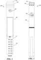
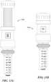
- FIG. 1depicts an unmodified disposable medication delivery device 100 similar to the Lantus ® SoloSTAR ® Pen manufactured by Sanofi-aventis U.S. LLC of Bridgewater, NJ, USA.
- FIG. 2depicts an unmodified durable (e.g ., reusable) medication delivery device 200 similar to the NovoPen ® 4 manufactured by Novo Nordisk A/S of Alle, Denmark.
- Embodiments of the present inventioncan be coupled to either of these two medication delivery devices 100, 200, as well as others, without modification of the devices.
- the pen-type medication delivery devices 100, 200include a medication reservoir 102 where the unused medication is stored.
- the unused medicationis injected into a patient through a detachable needle (not shown).
- the patientadjusts the dose knob 104, 204 by twisting the dose knob 104, 204 relative to the housing 106, 206 until an indication of the desired medication dose appears in the dose window 108, 208.
- the dose knob 104, 204As shown in FIGs. 3A and 3B , as the dose knob 104, 204 is twisted, the dose knob 104, 204 extends away from the housing 106, 206 revealing a dose stem 302 with dose markings 304.
- the dose stem 302continues to extend until the patient has set the desired dose.
- the dose stem 302retracts into the housing 106, 206 and causes a plunger 112 at the top of the medication reservoir 102 to compress the medication through the needle (not shown).
- the dose stem 302 of medication delivery device 300 in FIG. 3Ais retracted into the housing 106 and thus, is not visible except through the dose window 108.
- the dose stem 302 in the delivery device 300 of FIG. 3Bis extended and the dose markings 304 can be seen spiraling around the dose stem 302.
- FIG. 4depicts a lower case 400 and FIG. 5 depicts an upper case 500 of an automated dose setting apparatus according to embodiments of the inventions.
- the lower case 400 and upper case 500are attached to a conventional medication delivery device 100, 200 so that an analyte measurement system or other device can communicate a correct dose to the automated dose setting apparatus which in turn sets the dose to be administered without the patient having to determine the dose or turn the knob the correct number of turns.
- the lower case 400includes a compression fitting 402 that allows the lower case 400 to be securely fastened to the housing 106, 206 of the medication delivery device 100, 200.
- the compression fittingis adapted to securely couple to a wide range of medication devices including devices having a housing outer diameter of approximately 15 mm to approximately 25 mm. In some embodiments, other diameters can be accommodated with larger or smaller compression fittings and/or adapters. In other embodiments, different arrangements can be used to couple the lower case 400 to the medication delivery device 100, 200.
- the lower case 400also includes a display 404 for providing an indication of the dose set by the automated dose setting apparatus.
- the lower case 400houses a controller and associated electronics (e.g ., memory, wiring, transceiver, sensors, etc .) adapted to operate the display 404 to indicate the dose.
- the upper case 500includes a cylinder shaft 502 with tooth fluting that is adapted to go over the dosing stem and rotatably couple to the lower case 400.
- the upper case 500further includes a knob cover 504 that is adapted to securely couple to the dose knob 104, 204 of the medication delivery device 100, 200 using a gasket.
- the knob cover 504can include an opening to allow access to the injection button 110, 210 and in other embodiments, the knob cover 504 can include an extension button 506 that contacts and actuates the injection button 110, 210 when depressed.
- FIGs. 6A and 6Bdepict a cross-sectional view and a side view, respectively, of the assembled automated dose setting apparatus 600 including the lower case 400 rotatably coupled to the upper case 500.
- the lower case 400can house a power supply 602 (e.g., one or more batteries) and an electronic circuit 604 (e.g., on a flexible circuit board that conforms to the inner diameter of the lower case 400) that can include a controller 606 (e.g., a microcontroller with memory 608), a driver assembly 610 (e.g., a Piezo stepper motor), a sensor assembly 612 (e.g., one or more capacitive/optical/magnetic position sensors), and a transceiver 614 (e.g., a radio frequency (RF) receiver/transmitter module).
- a clock generator 616e.g., an oscillator
- a time and date clock modulee.g., a time and date clock module
- the upper case 500includes the cylinder shaft 502 which is adapted to both be rotatably driven by the driver assembly 610 in the lower case 400 and to be position monitored by the sensor 612 which is also in the lower case 400.
- the upper case 500can be made from aluminum and/or hard plastic. Other materials can be used.
- a gasket 620is provided to secure the upper case 500 to the dose knob 104 of the medication delivery device 100, 200.
- cylinder shaft 502which is attached to the knob cover 504 which is coupled to the dose knob 104 via gasket 620, is linked to the dose knob 104.
- the gasket 620can be made from rubber or similar material. Other materials can be used for the gasket 620 and various alternative methods can be used to secure the knob cover 504 to the dose knob 104.
- electronic circuit 604is adapted to track the rotational movement of the cylinder shaft 502 as the dose stem 302 is extended and/or retracted. As the teeth on the surface of the cylinder shaft 502 move past the sensor 612, the controller 606 can track the dosage setting or administration of the medication delivery device 100, 200.
- the controller 606can receive information (e.g ., via a wireless signal from an analyte measurement system or other health data manager device (e.g., smart phone, tablet, PC, wrist computer, etc .)) indicating an intended dosage to be next administered.
- the controller 606can use the driver assembly 610 to automatically set the medication delivery device 100, 200 to the intended dosage based on the received information.
- the controller 606can further provide a confirmation indication to the patient (e.g ., via status LEDs or audio tones) that the amount set to be administered is correct or an alarm if the amount set to be administered is different than the intended amount ( e.g ., in an error condition). Likewise, the controller 606 can provide a confirmation indication to the patient ( e.g ., via status LEDs or audio tones) if the amount actually administered is correct or an alarm if the amount actually administered is different than the intended amount.
- the controller 606can wirelessly transmit a signal to an analyte measurement system or other health data manager device (e.g ., smart phone, tablet, PC, wrist computer, etc .) that indicates the amount of medication that was administered using the medication delivery device coupled to the automated dose setting apparatus 600.
- an analyte measurement system or other health data manager devicee.g ., smart phone, tablet, PC, wrist computer, etc .
- a time and date of the administrationcan also be transmitted.
- FIG. 7is a block diagram depicting an example system architecture 700 for some embodiments of the automated dose setting apparatus 600.
- the system architecture 700can include the controller 606 (e.g., a microcontroller with memory 608) that executes program instructions stored in the memory 608 to perform various methods of the present invention. Coupled to the controller 606, the system architecture 700 can further include the power supply 602 ( e.g., one or more batteries), the driver assembly 610 ( e.g., a Piezo stepper motor) including actuators 702, the sensor assembly 612 ( e.g ., including one or more capacitive/optical/magnetic sensors for tracking knob/shaft position and/or reading other encoded markings on the cylinder shaft 502, FIG.
- the controller 606e.g., a microcontroller with memory 608
- the system architecture 700can further include the power supply 602 (e.g., one or more batteries), the driver assembly 610 (e.g., a Piezo stepper motor) including actuators 70
- the transceiver 614e.g., a radio frequency (RF) receiver/transmitter module
- RFradio frequency
- Other devicescan also be coupled to the controller 606 such as the clock generator 616 (e.g., an oscillator), a time and date clock module 706, and the display driver circuitry 618 to drive the display 404.
- the power supplycan be coupled to the driver assembly 610, the sensor assembly 612, the transceiver 614, the clock generator 616, the time and date clock module 706, the display driver circuitry 618, and the display 404.
- FIG. 8depicts details of the compression fitting 402 for securing the lower case 400 to the housing 106 of the medication delivery device 100 by illustrating a magnified view of the area surrounded by the dashed lines labeled AA in FIG. 6A .
- a flexible, hollow, threaded cone 802is provided at the base of the lower case 400 including a gap (not shown in FIG. 8 but see 406 of FIG. 4 ).
- the threaded cone 802is placed around the housing 106 of the medication delivery device 100 and a compression nut 806 including ridges 808 for grip is screwed onto the threaded cone 802.
- the threaded cone 802extends up along the lower case 400, the threads 810 increase in diameter and in response to the compression nut 806 being tightened, the threaded cone 802 is compressed and constricted around the housing 106, securing the lower case 400 to the housing 106 of the medication delivery device 100.
- the lower case 400 including the threaded cone 802is made from a semi-flexible material such as aluminum or polyethylene and the compression nut 806 is made from nylon or other hard plastic. Many other practicable materials can be used for these components.
- FIG. 9depicts a cross-sectional view of the upper case 500 taken at cut line BB of FIG. 7 .
- the tooth fluting of the cylinder shaft 502gives the outer surface of the cylinder shaft 502 a gear-shaped cross-section.
- FIG. 10depicts a cross-sectional view of the upper case 500 inserted into the lower case 400 taken at cut line CC of FIG. 7 .
- This viewillustrates the position of the driver assembly 610 relative to the cylinder shaft 502.
- actuators 1002, 1004 within the driver assembly 610are disposed to engage the tooth fluting of the cylinder shaft 502 to cause the cylinder shaft 502 to rotate. Operation of the driver assembly 610 is described in more detail below with respect to FIGs. 12A to 12C .
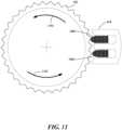
- FIG. 11depicts a magnified schematic representation of an example embodiment of the driver assembly 610 depicted in the cross-sectional view of FIG. 10 .
- the actuators 1002, 1004 of the driver assembly 610alternately press against the teeth of the outer surface of the cylinder shaft 502. These alternating linear forces are thus translated into rotational force to drive the cylinder shaft 502 to rotate about its longitudinal axis as indicated by arrows 1102.
- the cylinder shaft 502is coupled to the knob cover 504 ( FIG. 6A ) which is secured to the dose knob 104 ( FIG. 6A ).
- the driver assembly 610is adapted to turn the dose knob 104 when the upper case 500 and lower case 400 are attached to a medication delivery device 100, 200.
- the cylinder shaft 502 of the upper case 500is made from a material such as aluminum or hard plastic and the actuators 1002, 1004 of the driver assembly 610 are made from piezoelectric material, such as, for example, barium titanate, lead titanate, lead zirconate titanate, potassium niobate, lithium niobate, lithium tantalite, or sodium tungstate. Many other practicable materials can be used for these components.
- FIGs. 12A through 12Cdepict an example sequence of operation of the driver assembly 610.
- the driver assembly 610can include two actuators 1002, 1004 that are controlled to activate sequentially.
- a repeating sequence as represented by FIGs. 12A through 12Ccan be used to precisely turn the cylinder shaft 502 (and ultimately the dose knob 104, 204) to a desired position.
- Embodiments of the inventioninclude the controller 606 receiving a signal indicating a desired dose (e.g., from an analyte monitoring system or other device) and determining how many repetitions of the sequence would be required to set the attached medication delivery device to the desired dose.
- an electrical signal from the controller 606is applied to the first actuator 1002.
- the first actuator 1002 of the driver assembly 610which can include a Piezo material, expands to push against a tooth of the cylinder shaft 502.
- the cylinder shaft 502rotates in the direction of the arrow 1102 (e.g., counter-clockwise) a single “step” in response to the linear force from the first actuator 1002.
- the controller 606removes the electrical signal from the first actuator 1002 and the first actuator 1002 contracts away from the cylinder shaft 502. Note that the first actuator 1002 contracts a sufficient amount to be clear of the teeth of the cylinder shaft 502.
- the controller 606applies an electrical signal to the second actuator 1004.
- the second actuator 1004thus expands and pushes against another tooth of the cylinder shaft 502.
- the cylinder shaftrotates in the direction of the arrow 1102 (e.g., counter-clockwise) a single “step” in response to the linear force from the second actuator 1002.
- the controller 606removes the electrical signal from the second actuator 1004 and the second actuator 1004 contracts away from the cylinder shaft 502. Note that the second actuator 1004 contracts a sufficient amount to be clear of the teeth of the cylinder shaft 502.
- the controller 606is able to determine when the dose knob 104, 204 has been rotated the desired amount. In some embodiments, the controller 606 can be further adapted to cause the display 404 to provide an indication of the dose that has been set by the controller.
- FIG. 13Adepicts a view of an example embodiment of a fully assembled automated dose setting apparatus 1300 attached to a medication delivery device 100, 200 ( FIGs. 1 and 2 ).
- the automated dose setting apparatus 1300is shown in the extended position.
- FIG. 13Bdepicts a view of the example embodiment of a fully assembled automated dose setting apparatus 1300 attached to a medication delivery device 100, 200 ( FIGs. 1 and 2 ).
- the automated dose setting apparatus 1300is shown in the retracted position.
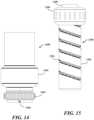
- an automated dose monitoring apparatusthat is adapted to be attached to any conventional pen-type medication delivery device 100, 200.
- an automated dose monitoring apparatusincludes a lower case 1400 and an upper case 1500, both adapted to be attached to a medication delivery device 100, 200.
- FIG. 14depicts an example embodiment of a lower case of an automated dose monitoring apparatus according to some embodiments of the present invention.
- the lower case 1400includes a compression fitting 1402 that is similar to the compression fitting 402 of the lower case 400 of the automated dose setting apparatus 1300.
- the compression fitting 1402enables secure attachment of the lower case 1400 to the housing 106, 206 of the medication delivery device 100, 200.
- the lower case 1400also includes a body portion 1404 adapted to house and support electronics as will be discussed below.
- FIG. 15depicts an example embodiment of an upper case of an automated dose monitoring apparatus according to some embodiments of the present invention.
- the upper case 1500includes a transparent (or semi-transparent) cylinder shaft 1502 that includes dosage indicator markings 1504 (e.g., a spiral bar code strip).
- the upper case 1500also includes a knob cover 1506 and an extension button 1508 that contacts and actuates the injection button 110, 210 of the medication delivery device 100, 200 when the extension button 1508 is depressed.
- the knob cover 1506includes features for securing the upper case 1500 to the dose knob 104, 204 of the medication delivery device 100, 200.
- FIG. 16depicts a side view of an example assembled automated dose monitoring apparatus 1600 according to some embodiments of the present invention. As shown the, the cylinder shaft 1502 of the upper case 1500 is inserted into and rotatably coupled to the body portion 1404 of the lower case 1400.
- FIG. 17depicts a magnified view of the portion of the dosage indicator markings 1504 surrounded by dashed lines and labeled DD in FIG. 16 .
- the dosage indicator markings 1504can include two or more sets of indicators 1702, 1704.
- the indicator marks in the upper set of indicators 1702are consistently spaced and can be used for position synchronization. These indicator marks are spaced to correspond to the dose markings 304 on the medication delivery device's dose stem 302 ( FIG. 3B ).
- a second set of indicators 1704 at the lower portion of the spiral dosage indicator markings 1504can be used to provide an identifier code for medication type ( e.g ., insulin type).
- the cylinder shaft 1502is detachable and can be unique for different size medication containers and can include unique sets of indicators for different medications and for each type of a given medication ( e.g., insulin type 1, 2, 3, etc .).
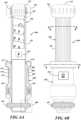
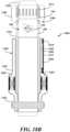
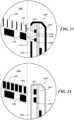
- FIGs. 18A and 18Bdepict cross-sectional views of an example embodiment of an automated dose monitoring apparatus 1600 attached to a medication delivery device 100, 200.
- the dosing stem 302 of the medication delivery device 100, 200is fully extended and in FIG. 18B , the dosing stem 302 is fully retracted.
- the lower case 1400can house a power supply 1802 (e.g., one or more batteries) and an electronic circuit 1804 (e.g., on a flexible circuit board that conforms to the inner diameter of the lower case 1400) that can include a controller 1806 (e.g., a microcontroller with memory 1808), a sensor assembly 1810 (e.g., one or more capacitive/optical/magnetic sensors), and a transceiver 1812 (e.g., a radio frequency (RF) receiver/transmitter module).
- RFradio frequency
- Additional devicescan also be included in the circuit 1804 and coupled to the controller such as a clock generator (e.g. , an oscillator), one or more status LEDs, a time and date clock module, and an audio output speaker.
- electronic circuit 1804is adapted to read the dosage indicator markings 1504 as the dose stem 302 is extended and/or retracted.
- the controller 1806can track the dosage setting of the medication delivery device.
- the controller 1806can receive information (e.g., via a wireless signal from an analyte measurement system or other health data manager device (e.g., smart phone, tablet, PC, wrist computer, etc .)) indicating an intended dosage to be next administered.
- the controller 1806can provide a confirmation indication to the patient (e.g ., via status LEDs or audio tones) if the amount set to be administered is correct or an alarm if the amount set to be administered is different than the intended amount. Likewise, the controller 1806 can provide a confirmation indication to the patient ( e.g. , via status LEDs or audio tones) if the amount actually administered is correct or an alarm if the amount actually administered is different than the intended amount.
- the controller 1806can wirelessly transmit a signal to an analyte measurement system or other health data manager device (e.g ., smart phone, tablet, PC, wrist computer, etc .) that indicates the amount of medication that was administered using the medication delivery device coupled to the automated dose monitoring apparatus 1600.
- an analyte measurement system or other health data manager devicee.g ., smart phone, tablet, PC, wrist computer, etc .
- a time and date of the administrationcan also be transmitted.
- a gasket 1814is provided to secure the upper case 1500 to the dose knob 104 of the medication delivery device 100, 200.
- the gasket 1814can be made from rubber or similar material. Other materials can be used for the gasket 1814 and various alternative methods can be used to secure the knob cover 1506 to the dose knob 104.
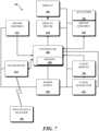
- FIG. 19is a block diagram depicting an example system architecture 1900 for some embodiments of the automated dose monitoring apparatus 1600.
- the system architecture 1900can include the controller 1806 (e.g., a microcontroller with memory 1808) that executes program instructions stored in the memory 1808 to perform various methods of the present invention. Coupled to the controller 1806 (e.g., to send and/or receive control signals and/or data signals), the system architecture 1900 can further include the sensor assembly 1810 (e.g ., including one or more capacitive/optical/magnetic sensors for tracking knob/shaft position and/or reading other encoded markings on the cylinder shaft 1502, FIG.
- the controller 1806e.g., a microcontroller with memory 1808
- the system architecture 1900can further include the sensor assembly 1810 (e.g ., including one or more capacitive/optical/magnetic sensors for tracking knob/shaft position and/or reading other encoded markings on the cylinder shaft 1502, FIG.
- the transceiver 1812e.g., a radio frequency (RF) receiver/transmitter module
- a health data manager device 1902e.g., an analyte measurement system or health data manager software running on a smart phone, tablet, PC, wrist computer, etc.
- Other devicescan also be coupled to the controller 1806 to send and/or receive control signals and/or data signals such as the clock generator 1904 (e.g., an oscillator), a time and date clock module 1906, and the output driver 1908 to drive an audio speaker and/or status LEDs 1910.
- the power supply 1802e.g., one or more batteries
- the power supply 1802can be coupled to the sensor assembly 1810, the transceiver 1812, the clock generator 1904, the time and date clock module 1906, and the output driver 1908.
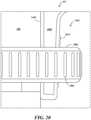
- FIG. 20depicts details of the compression fitting 1402 for securing the lower case 1400 to the housing 106 of the medication delivery device 100 by illustrating a magnified view of the area surrounded by the dashed lines labeled EE in FIG. 18A .
- a flexible, hollow, threaded cone 2002is provided at the base of the lower case 1400 including a gap (not shown in FIG. 18A or 20 but see 1406 of FIG. 14 ).
- the threaded cone 2002is placed around the housing 106 of the medication delivery device 100 and a compression nut 2006 including ridges 2008 for grip is screwed onto the threaded cone 2002.
- the threads 2010increase in diameter and in response to the compression nut 2006 being tightened, the threaded cone 2002 is compressed and constricted around the housing 106, securing the lower case 1400 to the housing 106 of the medication delivery device 100.
- the lower case 1400 including the threaded cone 2002is made from a semi-flexible material such as aluminum or hard plastic and the compression nut 2006 is made from nylon or hard plastic. Many other practicable materials can be used for these components.
- FIG. 21depicts a magnified view of a portion of the knob cover 1506 surrounded by dashed lines and labeled FF in FIG. 18A .
- this detailillustrates that cylinder shaft 1502 is attached to the knob cover 1506.
- knob cover 1506is coupled to the dose knob 104 via gasket 1814, cylinder shaft 1502 is linked to the dose knob 104.
- FIG. 22depicts a magnified view of a portion of the electronic circuit 1804 surrounded by dashed lines and labeled GG in FIG. 18A .
- this detailillustrates the sensor assembly 1810 which is part of the electronic circuit 1804.
- the sensor assembly 1810can include one or more emitter/detector pairs 2202/2204, 2206/2208 mounted on the circuit board of the electronic circuit 1804 and disposed so as to generally face the outer surface of the cylinder shaft 1502 and in particular, the dosage indicator markings 1504 (e.g., the spiral bar code strip) on the cylinder shaft 1502 through a sensor window 2210 in the lower casing 1404.
- the dosage indicator markings 1504e.g., the spiral bar code strip
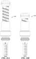
- FIG. 23depicts an example of an optical sensor assembly 2300 according to some embodiments of the present invention.
- two emitter/detector pairs 2202/2204, 2206/2208are mounted on the circuit board of the electronic circuit 1804 and disposed so as to face the dosage indicator markings 1504 (e.g., the spiral bar code strip) on the cylinder shaft 1502 through a sensor window 2210 in the body portion 1404 of the lower casing 1400.
- the upper emitter/detector pair 2202/2204is disposed to align with the upper set of indicators 1702 which can be used for synchronization and dose knob position tracking. These indicator marks are spaced to correspond to the dose markings 304 on the medication delivery device's dose stem 302 ( FIG. 3B ).
- the lower emitter/detector pair 2206/2208is disposed to align with the second set of indicators 1704 at the lower portion of the spiral dosage indicator markings 1504. These indicators 1704 can be read to determine an identifier code for medication type (e.g ., insulin type).
- medication typee.g ., insulin type
- the optical sensor assembly 2300reads the dosage indicator markings 1504 (e.g., the spiral bar code strip) created with printed marks having a high contrast relative to the background.
- An LEDcan be used as an emitter to shine light on the dosage indicator markings 1504 and a light detector can sense the reflection of the light from the dosage indicator markings 1504.
- the light sensor assembly 2300detects changing reflection levels each time one of the indicator marks 1702 passes by the sensor window 2210.
- Each indicator mark 1702represents one tick and corresponds to a fixed volume of medication being set for dosing.
- the sensor assembly 2300reads synchronization/position indicator marks 1702.
- the number of indicator marks 1702is proportional to the angle of dose knob rotation and is proportional to selected medication dose. Concurrently, a medication type code can be read from the lower portion of the dosage indicator markings 1504. The length of each indicator mark 1704 can be interpreted as a digital numeric value as described below with respect to the timing diagrams of FIG. 25 .
- FIG. 24depicts an alternative example of a magnetic or capacitive sensor assembly 2400 according to some embodiments of the present invention.
- two magnetic or capacitive sensors 2402, 2404are mounted on the circuit board of the electronic circuit 1804 and disposed so as to face the dosage indicator markings 1504 (e.g., the spiral bar code strip) on the cylinder shaft 1502 through the body portion 1404 of the lower casing 1400.
- the dosage indicator markings 1504e.g., the spiral bar code strip
- the upper magnetic or capacitive sensor 2402is disposed to align with an upper set of metallic indicators 2406 which can be used for synchronization and dose knob position tracking.
- metallic indicators 2406, 2408are used in place of dark markings so that the magnetic or capacitive sensors 2402, 2406 can detect the indicators 2406, 2408. These indicator marks are spaced to correspond to the dose markings 304 on the medication delivery device's dose stem 302 ( FIG. 3B ).
- the lower magnetic or capacitive sensor 2404is disposed to align with a second set of metallic indicators 2408 at the lower portion of the spiral dosage indicator markings 1504. These indicators 2408 can be read to determine an identifier code for medication type (e.g ., insulin type).
- a magnetic sensor assembly and a capacitive sensor assemblyboth function in a similar manner.
- metalized padsare printed or affixed as the dosage indicator markings 1504 on the cylinder shaft 1502. The presence of a metalized pad changes the capacitance detected by the capacitive sensor. As the cylinder shaft 1502 rotates past each metallized pad, a tick is counted corresponding to a fixed volume of medication being set for dosing.
- a magnetic sensor assemblycan be used to read the indicator markings 1504 on the cylinder shaft 1502.
- a magnetic sensor assemblycan use a multi-pole ring magnet with alternating North and South polarities. As the cylinder shaft 1502 rotates about the medication delivery device, a Hall Effect sensor detects the changing polarities. Each polarity change represents one tick and corresponds to a fixed volume of medication being set for dosing.
- FIG. 25depicts examples of timing diagrams for interpreting the dosage indicator markings 1504 (e.g., the spiral bar code strip) on the cylinder shaft 1502 according to some embodiments of the present invention. These examples are applicable to any type of sensor (e.g., optical, magnetic, capacitive, etc.) used.
- the synchronization and knob position timing diagram 2502is generated from sensing the upper indicators 1702, 2406 of the dosage indicator markings 1504 on the cylinder shaft 1502. This timing diagram 2502 provides a synchronization clock signal by which the signals from the lower indicators 1704, 2408 are examined. In other words, on each falling edge of the synchronization and knob position timing diagram 2502, the value of the signal from the lower indicators 1704, 2408 is read.
- FIG. 25depicts examples of timing diagrams for interpreting the dosage indicator markings 1504 (e.g., the spiral bar code strip) on the cylinder shaft 1502 according to some embodiments of the present invention. These examples are applicable to any type of sensor (e.g., optical, magnetic,
- the numeric value of the first (i.e., top most) example timing diagram 2504is an eight bit binary code for insulin type no. 1 and is "10001000" which is "136" in decimal.
- the numeric value of the second ( i.e ., middle) example timing diagram 2506is an eight bit binary code for insulin type no. 2 and is "11011000” which is "216" in decimal.
- the numeric value of the third ( i.e. , bottom most) example timing diagram 2508is an eight bit binary code for insulin type no. 3 and is "11111000” which is "248" in decimal.
- FIG. 26Adepicts a view of an example embodiment of a fully assembled automated dose monitoring apparatus 1600 in the extended position and coupled to the medication delivery device 100 of FIG. 1 .
- FIG. 26Bdepicts a view of an example embodiment of a fully assembled automated dose monitoring apparatus in the retracted position and is coupled to the medication delivery device 100 of FIG. 1 .
- the automated dose monitoring apparatus 1600 in FIG. 26Ais engaged and ready to be used to inject an 80 unit dose of medication (assuming a needle is attached).
- the automated dose monitoring apparatus 1600 in FIG. 26Bis disengaged.
- the automated dose setting apparatus 1300is attached to a medication delivery device 100 (2702).
- a signal from an analyte monitoring system or other health data management deviceis transmitted to the automated dose setting apparatus 1300 (2704).
- the signalincludes information indicating an appropriate dose of medication to be administered.
- the automated dose setting apparatus 1300drives the dose knob of the medication delivery device 100 to a setting corresponding to the received dose to be administered (2706).
- the automated dose setting apparatus 1300can monitor the setting of the dose to verify that the correct dose is actually set.
- the automated dose setting apparatus 1300can provide an indication that the correct dose is set or trigger an alarm if a dose different than the intended dose is set.
- the indication and/or alarmcan be via audible indicia and/or via a display.
- the automated dose setting apparatus 1300can monitor the administration of the medication by monitoring movement of the medication delivery device 100 during administration of the medication (2708). In such embodiments, the automated dose setting apparatus 1300 can transmit a signal to the analyte monitoring system or other health data management device indicating the dose (and type) of medication that was administered (2710).
- FIG. 28a flow chart depicting an example method 2800 according to some embodiments of the present invention is provided.
- the automated dose monitoring apparatus 1600is attached to a medication delivery device 100 (2802). Movement of the medication delivery device 100 is monitored by the automated dose monitoring apparatus 1600 during administration of the medication (2804).
- the automated dose monitoring apparatus 1600transmits a signal to an analyte monitoring system or other health data management device indicating the dose (and type) of medication that was administered (2806) along with a time and date of the administration.
Landscapes
- Health & Medical Sciences (AREA)
- Engineering & Computer Science (AREA)
- Public Health (AREA)
- General Health & Medical Sciences (AREA)
- Animal Behavior & Ethology (AREA)
- Veterinary Medicine (AREA)
- Hematology (AREA)
- Life Sciences & Earth Sciences (AREA)
- Biomedical Technology (AREA)
- Anesthesiology (AREA)
- Vascular Medicine (AREA)
- Heart & Thoracic Surgery (AREA)
- Chemical & Material Sciences (AREA)
- Bioinformatics & Cheminformatics (AREA)
- Medicinal Chemistry (AREA)
- Epidemiology (AREA)
- Medical Informatics (AREA)
- Primary Health Care (AREA)
- Infusion, Injection, And Reservoir Apparatuses (AREA)
Description
- The present application claims priority to
US Provisional Application No. 61/951,776 filed March 12, 2014 - The present invention relates to medication delivery devices, and more specifically to apparatus, systems, and methods for enhancement of such delivery devices.
- Many different medication delivery devices and physiological fluid analyte monitoring systems are commercially available. A common application of such devices is the infusion of insulin to and the monitoring of blood glucose levels of diabetic patients. Increased portability and ease of use of such devices have enabled diabetic patients to administer a self-regulated medical treatment regime, which in turn provides an increased level of patient autonomy and privacy. This is particularly beneficial since diabetic patients' glucose levels may vary daily or hourly.
- Such self-regulated diabetic treatment regimens often include the self-administration, either by injection and/or ingestion, of various medications,e.g., insulin. In addition to a high degree of medication compliance, for such self-regulated regimes to work effectively and safely, the patient is required to closely monitor the dosage and times at which medication is taken and may need to record or document corresponding medically relevant self-monitoring information,e.g., blood glucose level, insulin dosage,etc. The monitoring of such data helps to determine the current status and course of action (e.g., regimen change) of future actions. Because the recordation of this information can be time consuming and inconvenient, particularly if done with pen and paper, it is desirable that recordation, compilation and tracking of this type of information be minimized and time-efficient for the patient as possible.
- Accordingly, there is continued interest in the development of improved devices and methods for the patient-regulated administration of medication and associated monitoring and recordation of medical information, including but not limited to drug administration (e.g., injection) time and dosage, analyte concentration (e.g., glucose levels, and the like). Of particular interest would be the development of a patient-controlled medication administration and monitoring system which provides the patient with flexibility and control, increases convenience, privacy and ease of use for the patient, and enhances portability of system components. Thus, what are needed are systems, apparatus, and methods for enhancing medication delivery devices. Prior art administration and monitoring system are disclosed in
US 6 482 185 B1 andWO 2010/098927 A1 . - The invention, as defined in
independent claim 1, provides an apparatus for automatically setting a dosage of a medication delivery device. The apparatus includes a first portion coupleable onto a top of a manually-operated dose knob of a medication delivery device; and a second portion coupled to the first portion and coupleable onto a top of a housing of the medication delivery device. The second portion is operable to receive dose information electronically from an external device and to drive the first portion to operate the dose knob to set a dosage of the medication delivery device. - The invention, as defined in
independent method claim 8, provides a method for automatically setting a dosage of a medication delivery device. The method includes attaching an automated dose setting apparatus onto a top of a medication delivery device; receiving a first signal from an analyte monitoring system, the first signal indicating a dose of medication to be administered; and driving a manually-operated dose knob of the medication delivery device with the automated dose setting apparatus to set a dose corresponding with the dose of medication to be administered. - According to a further embodiment, an apparatus is provided for automatically monitoring a dosage of a medication delivery device. The apparatus includes a first portion coupleable to a dose knob of a medication delivery device; and a second portion coupleable to a housing of the medication delivery device. The second portion is operable to monitor movement of the first portion and to transmit a signal indicative of a dose of medication administered with the medication delivery device.
- Numerous other aspects are provided in accordance with these and other embodiments of the invention. Other features and aspects of embodiments of the present invention will become more fully apparent from the following detailed description, the appended claims, and the accompanying drawings.
FIG. 1 depicts an example of a disposable medication delivery device according to the prior art.FIG. 2 depicts an example of a durable medication delivery device according to the prior art.FIG. 3A depicts an example of a dosing stem of a medication delivery device in a retracted position according to the prior art.FIG. 3B depicts an example of a dosing stem of a medication delivery device in a fully extended position according to the prior art.FIG. 4 depicts an example embodiment of a lower case of an automated dose setting apparatus according to some embodiments of the present invention.FIG. 5 depicts an example embodiment of an upper case of an automated dose setting apparatus according to some embodiments of the present invention.FIG. 6A depicts a cross-sectional view of an example embodiment of an automated dose setting apparatus according to some embodiments of the present invention.FIG. 6B depicts a side view of an example embodiment of an automated dose setting apparatus according to some embodiments of the present invention.FIG. 7 depicts a block diagram of an example system architecture for an automated dose setting apparatus according to some embodiments of the present invention.FIG. 8 depicts a magnified view of the portion surrounded by dashed lines and labeled AA inFIG. 6A .FIG. 9 depicts a cross-sectional view taken at cut line BB ofFIG. 7 .FIG. 10 depicts a cross-sectional view taken at cut line CC ofFIG. 7 .FIG. 11 depicts a magnified schematic representation of an example embodiment of the driver assembly depicted in the cross-sectional view ofFIG. 10 .FIG. 12A to 12C depict an example of the operation of the driver assembly depicted in the cross-sectional view ofFIG. 10 .FIG. 13A depicts a view of an example embodiment of a fully assembled automated dose setting apparatus in the extended position coupled to the medication delivery device ofFIG. 1 according to some embodiments of the present invention.FIG. 13B depicts a view of an example embodiment of a fully assembled automated dose setting apparatus in the retracted position coupled to the medication delivery device ofFIG. 1 according to some embodiments of the present invention.FIG. 14 depicts an example embodiment of a lower case of an automated dose monitoring apparatus according to some embodiments of the present invention.FIG. 15 depicts an example embodiment of an upper case of an automated dose monitoring apparatus according to some embodiments of the present invention.FIG. 16 depicts a side view of an example embodiment of an automated dose monitoring apparatus according to some embodiments of the present invention.FIG. 17 depicts a magnified view of the portion surrounded by dashed lines and labeled DD inFIG. 16 .FIG. 18A depicts a cross-sectional view of an example embodiment of an automated dose monitoring apparatus attached to a medication delivery device with a fully extended dosing stem according to some embodiments of the present invention.FIG. 18B depicts a cross-sectional view of an example embodiment of an automated dose monitoring apparatus attached to a medication delivery device with the dosing stem in a retracted position according to some embodiments of the present invention.FIG. 19 depicts a block diagram of an example system architecture for an automated dose monitoring apparatus according to some embodiments of the present invention.FIG. 20 depicts a magnified view of the portion surrounded by dashed lines and labeled EE inFIG. 18A .FIG. 21 depicts a magnified view of the portion surrounded by dashed lines and labeled FF inFIG. 18A .FIG. 22 depicts a magnified view of the portion surrounded by dashed lines and labeled GG inFIG. 18A .FIG. 23 depicts an example of a sensor assembly according to some embodiments of the present invention.FIG. 24 depicts an alternative example of a sensor assembly according to some embodiments of the present invention.FIG. 25 depicts examples of timing diagrams according to some embodiments of the present invention.FIG. 26A depicts a view of an example embodiment of a fully assembled automated dose monitoring apparatus in the extended position and coupled to the medication delivery device ofFIG. 1 according to some embodiments of the present invention.FIG. 26B depicts a view of an example embodiment of a fully assembled automated dose monitoring apparatus in the retracted position and is coupled to the medication delivery device ofFIG. 1 according to some embodiments of the present invention.FIG. 27 depicts a flowchart representing an example method according to some embodiment of the present invention.FIG. 28 depicts a flowchart representing an example alternative method according to some embodiment of the present invention.- Embodiments of the present invention provide enhancements to medication delivery devices intended to be used by patients for self-administration of medication (e.g., insulin). In some embodiments, an automated dose setting apparatus is provided that is adapted to be attached to any conventional pen-type medication delivery device. The automated dose setting apparatus includes a controller adapted to receive a signal (e.g., wirelessly) from an analyte monitoring system (e.g., a blood glucose monitor) or other health data manager device (e.g., smart phone, tablet, PC, wrist computer,etc.) that specifies an appropriate medication dose to administer. The controller is further operative to control an actuator apparatus to automatically set the dose of the medication delivery device. Thus, the automated dose setting apparatus provides an enhancement attachment that can be added to existing pen-type medication delivery devices.
- In some other embodiments, an automated dose monitoring apparatus is provided that is adapted to be attached to any conventional pen-type medication delivery device. The automated dose monitor apparatus includes a controller adapted to receive a signal from one or more sensors coupled to the pen-type medication delivery device and to track the amount of medication that has been administered using the delivery device. The controller is further adapted to transmit a signal (e.g., wirelessly) that indicates the amount of medication that was actually administered along with a time and date of the administration. The signal is transmitted to an analyte monitoring system(e.g., a blood glucose monitor) or other health data manager device(e.g., smart phone, tablet, PC, wrist computer,etc.). Thus, the automated dose monitoring apparatus provides an enhancement attachment that can be added to existing pen-type medication delivery devices. In yet other embodiments, the principles of the invention can be applied to other types of medication delivery devices.
- Turning now to
FIGs. 1 and 2 , examples of conventional pen-typemedication delivery devices FIG. 1 depicts an unmodified disposablemedication delivery device 100 similar to the Lantus® SoloSTAR® Pen manufactured by Sanofi-aventis U.S. LLC of Bridgewater, NJ, USA.FIG. 2 depicts an unmodified durable (e.g., reusable)medication delivery device 200 similar to the NovoPen® 4 manufactured by Novo Nordisk A/S of Alle, Denmark. Embodiments of the present invention can be coupled to either of these twomedication delivery devices - The pen-type
medication delivery devices medication reservoir 102 where the unused medication is stored. The unused medication is injected into a patient through a detachable needle (not shown). The patient adjusts thedose knob dose knob housing dose window FIGs. 3A and 3B , as thedose knob dose knob housing dose stem 302 withdose markings 304. Thedose stem 302 continues to extend until the patient has set the desired dose. The patient then can inject the medication by holding down theinjection button dose knob injection button dose stem 302 retracts into thehousing plunger 112 at the top of themedication reservoir 102 to compress the medication through the needle (not shown). Thus, thedose stem 302 ofmedication delivery device 300 inFIG. 3A is retracted into thehousing 106 and thus, is not visible except through thedose window 108. The dose stem 302 in thedelivery device 300 ofFIG. 3B is extended and thedose markings 304 can be seen spiraling around thedose stem 302. - When patients use conventional
medication delivery devices dose knob - Embodiments of the present invention avoid these potential errors by automating dose setting.
FIG. 4 depicts alower case 400 andFIG. 5 depicts anupper case 500 of an automated dose setting apparatus according to embodiments of the inventions. Thelower case 400 andupper case 500 are attached to a conventionalmedication delivery device - The
lower case 400 includes a compression fitting 402 that allows thelower case 400 to be securely fastened to thehousing medication delivery device lower case 400 to themedication delivery device - The
lower case 400 also includes adisplay 404 for providing an indication of the dose set by the automated dose setting apparatus. As will be described in detail below, thelower case 400 houses a controller and associated electronics (e.g., memory, wiring, transceiver, sensors,etc.) adapted to operate thedisplay 404 to indicate the dose. - The
upper case 500 includes acylinder shaft 502 with tooth fluting that is adapted to go over the dosing stem and rotatably couple to thelower case 400. Theupper case 500 further includes aknob cover 504 that is adapted to securely couple to thedose knob medication delivery device knob cover 504 can include an opening to allow access to theinjection button knob cover 504 can include anextension button 506 that contacts and actuates theinjection button FIGs. 6A and 6B depict a cross-sectional view and a side view, respectively, of the assembled automateddose setting apparatus 600 including thelower case 400 rotatably coupled to theupper case 500. As can be seen most clearly inFIG. 6A , thelower case 400 can house a power supply 602(e.g., one or more batteries) and an electronic circuit 604(e.g., on a flexible circuit board that conforms to the inner diameter of the lower case 400) that can include a controller 606(e.g., a microcontroller with memory 608), a driver assembly 610(e.g., a Piezo stepper motor), a sensor assembly 612(e.g., one or more capacitive/optical/magnetic position sensors), and a transceiver 614(e.g., a radio frequency (RF) receiver/transmitter module). Other devices can also be included in thecircuit 604 such as a clock generator 616(e.g., an oscillator), a time and date clock module, and display driver circuitry 618(e.g., to drive the display 404).- The
upper case 500 includes thecylinder shaft 502 which is adapted to both be rotatably driven by thedriver assembly 610 in thelower case 400 and to be position monitored by thesensor 612 which is also in thelower case 400. Theupper case 500 can be made from aluminum and/or hard plastic. Other materials can be used. - Also visible in the cross-sectional view of
FIG. 6A , within theknob cover 504 of theupper case 500, agasket 620 is provided to secure theupper case 500 to thedose knob 104 of themedication delivery device cylinder shaft 502 which is attached to theknob cover 504 which is coupled to thedose knob 104 viagasket 620, is linked to thedose knob 104. In some embodiments, thegasket 620 can be made from rubber or similar material. Other materials can be used for thegasket 620 and various alternative methods can be used to secure theknob cover 504 to thedose knob 104. - In operation,
electronic circuit 604 is adapted to track the rotational movement of thecylinder shaft 502 as thedose stem 302 is extended and/or retracted. As the teeth on the surface of thecylinder shaft 502 move past thesensor 612, thecontroller 606 can track the dosage setting or administration of themedication delivery device transceiver 614, in some embodiments, thecontroller 606 can receive information (e.g., via a wireless signal from an analyte measurement system or other health data manager device (e.g., smart phone, tablet, PC, wrist computer,etc.)) indicating an intended dosage to be next administered. As will be described in detail below with respect toFIGs. 12A through 12C , thecontroller 606 can use thedriver assembly 610 to automatically set themedication delivery device - The
controller 606 can further provide a confirmation indication to the patient (e.g., via status LEDs or audio tones) that the amount set to be administered is correct or an alarm if the amount set to be administered is different than the intended amount (e.g., in an error condition). Likewise, thecontroller 606 can provide a confirmation indication to the patient (e.g., via status LEDs or audio tones) if the amount actually administered is correct or an alarm if the amount actually administered is different than the intended amount. In addition, using thetransceiver 614, in some embodiments, thecontroller 606 can wirelessly transmit a signal to an analyte measurement system or other health data manager device (e.g., smart phone, tablet, PC, wrist computer,etc.) that indicates the amount of medication that was administered using the medication delivery device coupled to the automateddose setting apparatus 600. In some embodiments, a time and date of the administration can also be transmitted. FIG. 7 is a block diagram depicting anexample system architecture 700 for some embodiments of the automateddose setting apparatus 600. Thesystem architecture 700 can include the controller 606(e.g., a microcontroller with memory 608) that executes program instructions stored in thememory 608 to perform various methods of the present invention. Coupled to thecontroller 606, thesystem architecture 700 can further include the power supply 602 (e.g., one or more batteries), the driver assembly 610 (e.g., a Piezo stepper motor) includingactuators 702, the sensor assembly 612 (e.g., including one or more capacitive/optical/magnetic sensors for tracking knob/shaft position and/or reading other encoded markings on thecylinder shaft 502,FIG. 5 ), and the transceiver 614 (e.g., a radio frequency (RF) receiver/transmitter module) for wireless communication with a health data manager device 704(e.g., an analyte measurement system or health data manager software running on a smart phone, tablet, PC, wrist computer, etc.). Other devices can also be coupled to thecontroller 606 such as the clock generator 616(e.g., an oscillator), a time anddate clock module 706, and thedisplay driver circuitry 618 to drive thedisplay 404. In addition to thecontroller 606, the power supply can be coupled to thedriver assembly 610, thesensor assembly 612, thetransceiver 614, theclock generator 616, the time anddate clock module 706, thedisplay driver circuitry 618, and thedisplay 404.FIG. 8 depicts details of the compression fitting 402 for securing thelower case 400 to thehousing 106 of themedication delivery device 100 by illustrating a magnified view of the area surrounded by the dashed lines labeled AA inFIG. 6A . A flexible, hollow, threadedcone 802 is provided at the base of thelower case 400 including a gap (not shown inFIG. 8 but see 406 ofFIG. 4 ). The threadedcone 802 is placed around thehousing 106 of themedication delivery device 100 and a compression nut 806 includingridges 808 for grip is screwed onto the threadedcone 802. As the threadedcone 802 extends up along thelower case 400, thethreads 810 increase in diameter and in response to the compression nut 806 being tightened, the threadedcone 802 is compressed and constricted around thehousing 106, securing thelower case 400 to thehousing 106 of themedication delivery device 100. In some embodiments, thelower case 400 including the threadedcone 802 is made from a semi-flexible material such as aluminum or polyethylene and the compression nut 806 is made from nylon or other hard plastic. Many other practicable materials can be used for these components.FIG. 9 depicts a cross-sectional view of theupper case 500 taken at cut line BB ofFIG. 7 . Note that the tooth fluting of thecylinder shaft 502 gives the outer surface of the cylinder shaft 502 a gear-shaped cross-section.FIG. 10 depicts a cross-sectional view of theupper case 500 inserted into thelower case 400 taken at cut line CC ofFIG. 7 . This view illustrates the position of thedriver assembly 610 relative to thecylinder shaft 502. As can be seen inFIG. 10 ,actuators driver assembly 610 are disposed to engage the tooth fluting of thecylinder shaft 502 to cause thecylinder shaft 502 to rotate. Operation of thedriver assembly 610 is described in more detail below with respect toFIGs. 12A to 12C . Also shown inFIG. 10 are thepower supply 602 and theelectronic circuit 604.FIG. 11 depicts a magnified schematic representation of an example embodiment of thedriver assembly 610 depicted in the cross-sectional view ofFIG. 10 . Theactuators driver assembly 610 alternately press against the teeth of the outer surface of thecylinder shaft 502. These alternating linear forces are thus translated into rotational force to drive thecylinder shaft 502 to rotate about its longitudinal axis as indicated byarrows 1102. Note that thecylinder shaft 502 is coupled to the knob cover 504 (FIG. 6A ) which is secured to the dose knob 104 (FIG. 6A ). Thus, thedriver assembly 610 is adapted to turn thedose knob 104 when theupper case 500 andlower case 400 are attached to amedication delivery device cylinder shaft 502 of theupper case 500 is made from a material such as aluminum or hard plastic and theactuators driver assembly 610 are made from piezoelectric material, such as, for example, barium titanate, lead titanate, lead zirconate titanate, potassium niobate, lithium niobate, lithium tantalite, or sodium tungstate. Many other practicable materials can be used for these components.FIGs. 12A through 12C depict an example sequence of operation of thedriver assembly 610. As described above, thedriver assembly 610 can include twoactuators FIGs. 12A through 12C can be used to precisely turn the cylinder shaft 502 (and ultimately thedose knob 104, 204) to a desired position. Embodiments of the invention include thecontroller 606 receiving a signal indicating a desired dose(e.g., from an analyte monitoring system or other device) and determining how many repetitions of the sequence would be required to set the attached medication delivery device to the desired dose.- In
FIG. 12A , an electrical signal from thecontroller 606 is applied to thefirst actuator 1002. Thefirst actuator 1002 of thedriver assembly 610, which can include a Piezo material, expands to push against a tooth of thecylinder shaft 502. Thecylinder shaft 502 rotates in the direction of the arrow 1102(e.g., counter-clockwise) a single "step" in response to the linear force from thefirst actuator 1002. In the second step, as depicted inFIG. 12B , thecontroller 606 removes the electrical signal from thefirst actuator 1002 and thefirst actuator 1002 contracts away from thecylinder shaft 502. Note that thefirst actuator 1002 contracts a sufficient amount to be clear of the teeth of thecylinder shaft 502. - In the third step of this example sequence, the
controller 606 applies an electrical signal to thesecond actuator 1004. Thesecond actuator 1004 thus expands and pushes against another tooth of thecylinder shaft 502. The cylinder shaft rotates in the direction of the arrow 1102(e.g., counter-clockwise) a single "step" in response to the linear force from thesecond actuator 1002. In the fourth step, not shown but would look the same as the depiction inFIG. 12B , thecontroller 606 removes the electrical signal from thesecond actuator 1004 and thesecond actuator 1004 contracts away from thecylinder shaft 502. Note that thesecond actuator 1004 contracts a sufficient amount to be clear of the teeth of thecylinder shaft 502. - This process can be repeated as many times as necessary to achieve the desired position of the
dose knob sensor 612 to detect movement of thecylinder shaft 502, thecontroller 606 is able to determine when thedose knob controller 606 can be further adapted to cause thedisplay 404 to provide an indication of the dose that has been set by the controller. FIG. 13A depicts a view of an example embodiment of a fully assembled automateddose setting apparatus 1300 attached to amedication delivery device 100, 200 (FIGs. 1 and 2 ). The automateddose setting apparatus 1300 is shown in the extended position.FIG. 13B depicts a view of the example embodiment of a fully assembled automateddose setting apparatus 1300 attached to amedication delivery device 100, 200 (FIGs. 1 and 2 ). The automateddose setting apparatus 1300 is shown in the retracted position.- Turning now to
FIGs 14 to 16 , an alternative embodiment of the present invention is described. In some embodiments, the invention provides an automated dose monitoring apparatus that is adapted to be attached to any conventional pen-typemedication delivery device dose setting apparatus 1300, an automated dose monitoring apparatus includes alower case 1400 and anupper case 1500, both adapted to be attached to amedication delivery device FIG. 14 depicts an example embodiment of a lower case of an automated dose monitoring apparatus according to some embodiments of the present invention. Thelower case 1400 includes acompression fitting 1402 that is similar to the compression fitting 402 of thelower case 400 of the automateddose setting apparatus 1300. Thecompression fitting 1402 enables secure attachment of thelower case 1400 to thehousing medication delivery device lower case 1400 also includes abody portion 1404 adapted to house and support electronics as will be discussed below. FIG. 15 depicts an example embodiment of an upper case of an automated dose monitoring apparatus according to some embodiments of the present invention. Theupper case 1500 includes a transparent (or semi-transparent)cylinder shaft 1502 that includes dosage indicator markings 1504(e.g., a spiral bar code strip). Theupper case 1500 also includes aknob cover 1506 and anextension button 1508 that contacts and actuates theinjection button medication delivery device extension button 1508 is depressed. Theknob cover 1506 includes features for securing theupper case 1500 to thedose knob medication delivery device FIG. 16 depicts a side view of an example assembled automateddose monitoring apparatus 1600 according to some embodiments of the present invention. As shown the, thecylinder shaft 1502 of theupper case 1500 is inserted into and rotatably coupled to thebody portion 1404 of thelower case 1400.FIG. 17 depicts a magnified view of the portion of thedosage indicator markings 1504 surrounded by dashed lines and labeled DD inFIG. 16 . In some embodiments, thedosage indicator markings 1504 can include two or more sets ofindicators indicators 1702 are consistently spaced and can be used for position synchronization. These indicator marks are spaced to correspond to thedose markings 304 on the medication delivery device's dose stem 302 (FIG. 3B ). A second set ofindicators 1704 at the lower portion of the spiraldosage indicator markings 1504 can be used to provide an identifier code for medication type (e.g., insulin type). Thecylinder shaft 1502 is detachable and can be unique for different size medication containers and can include unique sets of indicators for different medications and for each type of a given medication (e.g.,insulin type FIGs. 18A and18B depict cross-sectional views of an example embodiment of an automateddose monitoring apparatus 1600 attached to amedication delivery device FIG. 18A , thedosing stem 302 of themedication delivery device FIG. 18B , thedosing stem 302 is fully retracted.- As can be seen most clearly in
FIG. 18A , thelower case 1400 can house a power supply 1802(e.g., one or more batteries) and an electronic circuit 1804(e.g., on a flexible circuit board that conforms to the inner diameter of the lower case 1400) that can include a controller 1806(e.g., a microcontroller with memory 1808), a sensor assembly 1810(e.g., one or more capacitive/optical/magnetic sensors), and a transceiver 1812 (e.g., a radio frequency (RF) receiver/transmitter module). Additional devices can also be included in thecircuit 1804 and coupled to the controller such as a clock generator (e.g., an oscillator), one or more status LEDs, a time and date clock module, and an audio output speaker. - In operation,
electronic circuit 1804 is adapted to read thedosage indicator markings 1504 as thedose stem 302 is extended and/or retracted. As thedosage indicator markings 1504 move past thesensor assembly 1810, thecontroller 1806 can track the dosage setting of the medication delivery device. Using thetransceiver 1812, in some embodiments, thecontroller 1806 can receive information(e.g., via a wireless signal from an analyte measurement system or other health data manager device(e.g., smart phone, tablet, PC, wrist computer,etc.)) indicating an intended dosage to be next administered. Thecontroller 1806 can provide a confirmation indication to the patient (e.g., via status LEDs or audio tones) if the amount set to be administered is correct or an alarm if the amount set to be administered is different than the intended amount. Likewise, thecontroller 1806 can provide a confirmation indication to the patient (e.g., via status LEDs or audio tones) if the amount actually administered is correct or an alarm if the amount actually administered is different than the intended amount. In addition, using thetransceiver 1812, in some embodiments, thecontroller 1806 can wirelessly transmit a signal to an analyte measurement system or other health data manager device (e.g., smart phone, tablet, PC, wrist computer,etc.) that indicates the amount of medication that was administered using the medication delivery device coupled to the automateddose monitoring apparatus 1600. In some embodiments, a time and date of the administration can also be transmitted. - Also visible in the cross-sectional view of
FIG. 18A , within theknob cover 1506 of theupper case 1500, agasket 1814 is provided to secure theupper case 1500 to thedose knob 104 of themedication delivery device gasket 1814 can be made from rubber or similar material. Other materials can be used for thegasket 1814 and various alternative methods can be used to secure theknob cover 1506 to thedose knob 104. FIG. 19 is a block diagram depicting anexample system architecture 1900 for some embodiments of the automateddose monitoring apparatus 1600. Thesystem architecture 1900 can include the controller 1806(e.g., a microcontroller with memory 1808) that executes program instructions stored in thememory 1808 to perform various methods of the present invention. Coupled to the controller 1806(e.g., to send and/or receive control signals and/or data signals), thesystem architecture 1900 can further include the sensor assembly 1810 (e.g., including one or more capacitive/optical/magnetic sensors for tracking knob/shaft position and/or reading other encoded markings on thecylinder shaft 1502,FIG. 18A ), and the transceiver 1812(e.g., a radio frequency (RF) receiver/transmitter module) for wireless communication with a health data manager device 1902(e.g., an analyte measurement system or health data manager software running on a smart phone, tablet, PC, wrist computer, etc.). Other devices can also be coupled to thecontroller 1806 to send and/or receive control signals and/or data signals such as the clock generator 1904(e.g., an oscillator), a time anddate clock module 1906, and theoutput driver 1908 to drive an audio speaker and/orstatus LEDs 1910. In addition to thecontroller 1806, the power supply 1802(e.g., one or more batteries), can be coupled to thesensor assembly 1810, thetransceiver 1812, theclock generator 1904, the time anddate clock module 1906, and theoutput driver 1908.FIG. 20 depicts details of thecompression fitting 1402 for securing thelower case 1400 to thehousing 106 of themedication delivery device 100 by illustrating a magnified view of the area surrounded by the dashed lines labeled EE inFIG. 18A . A flexible, hollow, threadedcone 2002 is provided at the base of thelower case 1400 including a gap (not shown inFIG. 18A or20 but see 1406 ofFIG. 14 ). The threadedcone 2002 is placed around thehousing 106 of themedication delivery device 100 and acompression nut 2006 includingridges 2008 for grip is screwed onto the threadedcone 2002. As the threadedcone 2002 extends up along thelower case 1400, thethreads 2010 increase in diameter and in response to thecompression nut 2006 being tightened, the threadedcone 2002 is compressed and constricted around thehousing 106, securing thelower case 1400 to thehousing 106 of themedication delivery device 100. In some embodiments, thelower case 1400 including the threadedcone 2002 is made from a semi-flexible material such as aluminum or hard plastic and thecompression nut 2006 is made from nylon or hard plastic. Many other practicable materials can be used for these components.FIG. 21 depicts a magnified view of a portion of theknob cover 1506 surrounded by dashed lines and labeled FF inFIG. 18A . In particular, this detail illustrates thatcylinder shaft 1502 is attached to theknob cover 1506. Thus, sinceknob cover 1506 is coupled to thedose knob 104 viagasket 1814,cylinder shaft 1502 is linked to thedose knob 104.FIG. 22 depicts a magnified view of a portion of theelectronic circuit 1804 surrounded by dashed lines and labeled GG inFIG. 18A . In particular, this detail illustrates thesensor assembly 1810 which is part of theelectronic circuit 1804. In some embodiments, thesensor assembly 1810 can include one or more emitter/detector pairs 2202/2204, 2206/2208 mounted on the circuit board of theelectronic circuit 1804 and disposed so as to generally face the outer surface of thecylinder shaft 1502 and in particular, the dosage indicator markings 1504(e.g., the spiral bar code strip) on thecylinder shaft 1502 through asensor window 2210 in thelower casing 1404.FIG. 23 depicts an example of anoptical sensor assembly 2300 according to some embodiments of the present invention. In this embodiment, two emitter/detector pairs 2202/2204, 2206/2208 are mounted on the circuit board of theelectronic circuit 1804 and disposed so as to face the dosage indicator markings 1504(e.g., the spiral bar code strip) on thecylinder shaft 1502 through asensor window 2210 in thebody portion 1404 of thelower casing 1400. The upper emitter/detector pair 2202/2204 is disposed to align with the upper set ofindicators 1702 which can be used for synchronization and dose knob position tracking. These indicator marks are spaced to correspond to thedose markings 304 on the medication delivery device's dose stem 302 (FIG. 3B ). The lower emitter/detector pair 2206/2208 is disposed to align with the second set ofindicators 1704 at the lower portion of the spiraldosage indicator markings 1504. Theseindicators 1704 can be read to determine an identifier code for medication type (e.g., insulin type).- In operation, the
optical sensor assembly 2300 reads the dosage indicator markings 1504 (e.g., the spiral bar code strip) created with printed marks having a high contrast relative to the background. An LED can be used as an emitter to shine light on thedosage indicator markings 1504 and a light detector can sense the reflection of the light from thedosage indicator markings 1504. Thelight sensor assembly 2300 detects changing reflection levels each time one of the indicator marks 1702 passes by thesensor window 2210. Eachindicator mark 1702 represents one tick and corresponds to a fixed volume of medication being set for dosing. Thus, when thedose knob 104 is being rotated by turning theknob cover 1506, thesensor assembly 2300 reads synchronization/position indicator marks 1702. The number of indicator marks 1702 is proportional to the angle of dose knob rotation and is proportional to selected medication dose. Concurrently, a medication type code can be read from the lower portion of thedosage indicator markings 1504. The length of eachindicator mark 1704 can be interpreted as a digital numeric value as described below with respect to the timing diagrams ofFIG. 25 . FIG. 24 depicts an alternative example of a magnetic orcapacitive sensor assembly 2400 according to some embodiments of the present invention. In this embodiment, two magnetic orcapacitive sensors electronic circuit 1804 and disposed so as to face the dosage indicator markings 1504(e.g., the spiral bar code strip) on thecylinder shaft 1502 through thebody portion 1404 of thelower casing 1400. Note that an aperture or window is not required since the material used for thebody portion 1404 is transparent to electric and magnetic fields. The upper magnetic orcapacitive sensor 2402 is disposed to align with an upper set ofmetallic indicators 2406 which can be used for synchronization and dose knob position tracking. Note that in this embodiment,metallic indicators capacitive sensors indicators dose markings 304 on the medication delivery device's dose stem 302 (FIG. 3B ). The lower magnetic orcapacitive sensor 2404 is disposed to align with a second set ofmetallic indicators 2408 at the lower portion of the spiraldosage indicator markings 1504. Theseindicators 2408 can be read to determine an identifier code for medication type (e.g., insulin type).- In operation, a magnetic sensor assembly and a capacitive sensor assembly both function in a similar manner. Rather than using optically sensed marks that have contrasting light reflectivity with the area between the marks, metalized pads are printed or affixed as the
dosage indicator markings 1504 on thecylinder shaft 1502. The presence of a metalized pad changes the capacitance detected by the capacitive sensor. As thecylinder shaft 1502 rotates past each metallized pad, a tick is counted corresponding to a fixed volume of medication being set for dosing. - In some embodiments, a magnetic sensor assembly can be used to read the
indicator markings 1504 on thecylinder shaft 1502. A magnetic sensor assembly can use a multi-pole ring magnet with alternating North and South polarities. As thecylinder shaft 1502 rotates about the medication delivery device, a Hall Effect sensor detects the changing polarities. Each polarity change represents one tick and corresponds to a fixed volume of medication being set for dosing. FIG. 25 depicts examples of timing diagrams for interpreting the dosage indicator markings 1504(e.g., the spiral bar code strip) on thecylinder shaft 1502 according to some embodiments of the present invention. These examples are applicable to any type of sensor(e.g., optical, magnetic, capacitive, etc.) used. The synchronization and knob position timing diagram 2502 is generated from sensing theupper indicators dosage indicator markings 1504 on thecylinder shaft 1502. This timing diagram 2502 provides a synchronization clock signal by which the signals from thelower indicators lower indicators FIG. 25 , the dashed vertical lines that are projected up to the three example timing diagrams 2504, 2506, 2508 from the falling edges of the synchronization and knob position timing diagram 2502, reflect that the values of the signals plotted in the other timing diagrams 2504, 2506, 2508 are evaluated at points in time corresponding to the falling edges of the synchronization and knob position timing diagram 2502.- Thus, the numeric value of the first (i.e., top most) example timing diagram 2504 is an eight bit binary code for insulin type no. 1 and is "10001000" which is "136" in decimal. The numeric value of the second (i.e., middle) example timing diagram 2506 is an eight bit binary code for insulin type no. 2 and is "11011000" which is "216" in decimal. The numeric value of the third (i.e., bottom most) example timing diagram 2508 is an eight bit binary code for insulin type no. 3 and is "11111000" which is "248" in decimal.
FIG. 26A depicts a view of an example embodiment of a fully assembled automateddose monitoring apparatus 1600 in the extended position and coupled to themedication delivery device 100 ofFIG. 1 .FIG. 26B depicts a view of an example embodiment of a fully assembled automated dose monitoring apparatus in the retracted position and is coupled to themedication delivery device 100 ofFIG. 1 . The automateddose monitoring apparatus 1600 inFIG. 26A is engaged and ready to be used to inject an 80 unit dose of medication (assuming a needle is attached). The automateddose monitoring apparatus 1600 inFIG. 26B is disengaged.- Turning now to
FIG. 27 , a flow chart depicting anexample method 2700 according to some embodiments of the present invention is provided. Initially, the automateddose setting apparatus 1300 is attached to a medication delivery device 100 (2702). A signal from an analyte monitoring system or other health data management device is transmitted to the automated dose setting apparatus 1300 (2704). The signal includes information indicating an appropriate dose of medication to be administered. The automateddose setting apparatus 1300 drives the dose knob of themedication delivery device 100 to a setting corresponding to the received dose to be administered (2706). In some embodiments, the automateddose setting apparatus 1300 can monitor the setting of the dose to verify that the correct dose is actually set. In such embodiments, the automateddose setting apparatus 1300 can provide an indication that the correct dose is set or trigger an alarm if a dose different than the intended dose is set. In some embodiments, the indication and/or alarm can be via audible indicia and/or via a display. - In some embodiments, the automated
dose setting apparatus 1300 can monitor the administration of the medication by monitoring movement of themedication delivery device 100 during administration of the medication (2708). In such embodiments, the automateddose setting apparatus 1300 can transmit a signal to the analyte monitoring system or other health data management device indicating the dose (and type) of medication that was administered (2710). - Turning now to
FIG. 28 , a flow chart depicting anexample method 2800 according to some embodiments of the present invention is provided. Initially, the automateddose monitoring apparatus 1600 is attached to a medication delivery device 100 (2802). Movement of themedication delivery device 100 is monitored by the automateddose monitoring apparatus 1600 during administration of the medication (2804). The automateddose monitoring apparatus 1600 transmits a signal to an analyte monitoring system or other health data management device indicating the dose (and type) of medication that was administered (2806) along with a time and date of the administration. - The foregoing description discloses only example embodiments of the invention. Modifications of the above-disclosed apparatus, systems and methods which fall within the scope of the invention will be readily apparent to those of ordinary skill in the art. Accordingly, while the present invention has been disclosed in connection with example embodiments, it should be understood that other embodiments may fall within the scope of the invention, as defined by the following claims.
Claims (20)
- An apparatus (600), comprising:a first portion (500) coupleable onto a top of a manually-operated dose knob (104, 204) of a medication delivery device (100, 200); anda second portion (400) coupled to the first portion (500) and coupleable onto a top of a housing (106, 206) of the medication delivery device (100, 200),wherein the second portion (400) is operable to receive dose information electronically from an external device and to drive the first portion (500) to operate the dose knob (104, 204) to set a dosage of the medication delivery device (100, 200).
- The apparatus of claim 1 further comprising an electronic circuit (604) contained in the second portion (400) and wherein the electronic circuit (604) includes a controller (606), a driver assembly (610), and a transceiver (614).
- The apparatus of claim 2 wherein the driver assembly (610) includes two actuators (1002, 1004) operable to rotate the first portion (500).
- The apparatus of claim 2 wherein the electronic circuit (604) further includes a sensor assembly (612) operable to detect rotation of the first portion (500).
- The apparatus of claim 1 wherein the first portion (500) includes a cylinder shaft (502) having tooth fluting.
- The apparatus of claim 5 wherein the second portion (400) includes a driver assembly (610) operable to rotate the cylinder shaft (502) using alternating linear actuators (1002, 1004).
- The apparatus of claim 1 wherein the second portion (400) includes a display (404) operable to indicate a dosage setting of the medication delivery device (100, 200).
- A method (2700), comprising:attaching an automated dose setting apparatus (1300) onto a top of a medication delivery device (2702, 2802);receiving a first signal from an external analyte monitoring system, the first signal indicating a dose of medication to be administered (2704); anddriving a manually-operated dose knob of the medication delivery device with the automated dose setting apparatus to set a dose corresponding with the dose of medication to be administered (2706).
- The method of claim 8 further comprising:monitoring movement of the medication delivery device while the dose knob is driven by the automated dose setting apparatus (2708, 2804); andverifying that the dose set by the automated dose setting apparatus corresponds with the dose of medication to be administered.
- The method of claim 8 further comprising:monitoring movement of the medication delivery device while the medication is being administered (2708, 2804); andverifying that a dose of medication actually administered corresponds with the dose of medication to be administered.
- The method of claim 10 further comprising:providing an indication if the dose of medication actually administered corresponds with the dose of medication to be administered; andproviding an alarm if the dose of medication actually administered does not correspond with the dose of medication to be administered.
- The method of claim 8 further comprising:
transmitting a second signal to the analyte monitoring system from the automated dose setting apparatus, the second signal indicating a dose of medication actually administered (2710). - The method of claim 8 wherein attaching an automated dose setting apparatus (600) to a medication delivery device (100, 200) includes coupling a first portion (500) of the automated dose setting apparatus to the dose knob (104, 204) of the medication delivery device (100, 200).
- The method of claim 8 wherein attaching an automated dose setting apparatus (600) to a medication delivery device (100, 200) includes coupling a second portion (400) of the automated dose setting apparatus to a housing (106, 206) of the medication delivery device (100, 200).
- The method of claim 8 wherein driving a dose knob (104, 204) of the medication delivery device (100, 200) includes rotating a first portion (500) of the automated dose setting apparatus (600) coupled to the dose knob (104, 204) by driving the first portion (500) using a driver assembly (610) in a second portion (400) of the automated dose setting apparatus (600) that is coupled to a housing (106, 206) of the medication delivery device (100, 200).
- The method of claim 15 wherein driving the first portion (500) using a driver assembly (610) in the second portion (400) of the automated dose setting apparatus (600) includes rotating the first portion (500) using alternating linear actuators (1002, 1004).
- The apparatus (600, 1300, 1600) of claim 1 wherein:
the second portion (400, 1400) is operable to monitor movement of the first portion (500, 1500) and to transmit a signal (2710) electronically to an external device indicative of a dose of medication administered with the medication delivery device. - The apparatus (1600) of claim 17 wherein the first portion (1500) includes a transparent cylinder shaft (1502) operable to surround a dose stem (302) of the medication delivery device (300).
- The apparatus (1600) of claim 18 wherein the cylinder shaft (1502) includes at least one set of dosage indicator markings (1504) detectable by a sensor assembly within the second portion.
- The apparatus (600, 1300, 1600) of claim 17 wherein the first portion (500, 1500) is rotatably coupleable to the second portion (400, 1400).
Applications Claiming Priority (2)
| Application Number | Priority Date | Filing Date | Title |
|---|---|---|---|
| US201461951776P | 2014-03-12 | 2014-03-12 | |
| PCT/US2015/016167WO2015138093A2 (en) | 2014-03-12 | 2015-02-17 | Methods and apparatus for enhancing a medication delivery device |
Publications (2)
| Publication Number | Publication Date |
|---|---|
| EP3116567A2 EP3116567A2 (en) | 2017-01-18 |
| EP3116567B1true EP3116567B1 (en) | 2023-10-11 |
Family
ID=52697517
Family Applications (1)
| Application Number | Title | Priority Date | Filing Date |
|---|---|---|---|
| EP15711333.3AActiveEP3116567B1 (en) | 2014-03-12 | 2015-02-17 | Methods and apparatus for enhancing a medication delivery device |
Country Status (6)
| Country | Link |
|---|---|
| US (1) | US10503876B2 (en) |
| EP (1) | EP3116567B1 (en) |
| JP (2) | JP6728052B2 (en) |
| CN (1) | CN106456885B (en) |
| CA (1) | CA2942036A1 (en) |
| WO (1) | WO2015138093A2 (en) |
Families Citing this family (36)
| Publication number | Priority date | Publication date | Assignee | Title |
|---|---|---|---|---|
| DK3352818T3 (en)* | 2015-09-23 | 2020-03-16 | Sanofi Aventis Deutschland | DEVICE FOR FIXING TO AN INJECTION DEVICE |
| CN108348695B (en) | 2015-11-11 | 2021-04-02 | 诺和诺德股份有限公司 | Drug delivery device with information capture |
| US10857304B2 (en) | 2016-03-25 | 2020-12-08 | Eli Lilly And Company | Determination of a dose set and delivered in a medication delivery device |
| WO2017184401A1 (en) | 2016-04-19 | 2017-10-26 | Eli Lilly And Company | Determination of a dose in a medication delivery device using two moving arrays with teeth and a sensor |
| WO2017189168A1 (en)* | 2016-04-28 | 2017-11-02 | Becton, Dickinson And Company | Pen needle exchange system |
| CN113101462A (en)* | 2016-05-24 | 2021-07-13 | 赛诺菲-安万特德国有限公司 | Complementary device attached to drug delivery device, digital sleeve for drug delivery device and drug delivery device |
| EP3463514B1 (en)* | 2016-05-30 | 2024-01-10 | Novo Nordisk A/S | Drug delivery device with zero position adjustment feature |
| EP3463520B1 (en) | 2016-05-30 | 2024-01-24 | Novo Nordisk A/S | Mounting feature for accessory device |
| PT3484547T (en) | 2016-07-15 | 2022-05-19 | Lilly Co Eli | Dose detection module for a medication delivery device |
| CA3033232C (en) | 2016-08-12 | 2022-09-06 | Eli Lilly And Company | Dose sensing mechanism in a medication delivery device |
| JP7036803B2 (en) | 2016-09-09 | 2022-03-15 | サノフィ-アベンティス・ドイチュラント・ゲゼルシャフト・ミット・ベシュレンクテル・ハフツング | Data acquisition device for attachment to injection devices |
| CN118681096A (en)* | 2016-10-14 | 2024-09-24 | 艾斯曲尔医疗公司 | Housing element, auxiliary unit and drug delivery device |
| CA3041938A1 (en)* | 2016-10-28 | 2018-05-03 | Ascensia Diabetes Care Holdings Ag | Methods and apparatus for improved medication delivery devices |
| CN110248688B (en) | 2016-12-07 | 2022-03-11 | 赛诺菲 | Data collection device for attachment to injection device |
| WO2018111708A1 (en) | 2016-12-15 | 2018-06-21 | Eli Lilly And Company | Medication delivery device with sensing system |
| CN108201647A (en)* | 2016-12-19 | 2018-06-26 | 广东东阳光药业有限公司 | The syringe of syringe collecting method and automatic collection calibration data |
| CA3050752C (en) | 2017-02-28 | 2022-09-06 | Eli Lilly And Company | Dose detection and drug identification for a medication delivery device |
| WO2019014588A1 (en) | 2017-07-14 | 2019-01-17 | Valeritas, Inc. | Communication accessory for a drug delivery device |
| US20190022328A1 (en)* | 2017-07-21 | 2019-01-24 | Verily Life Sciences Llc | Dosage measurement system in a pen button |
| ES2985951T3 (en) | 2017-08-18 | 2024-11-07 | Lilly Co Eli | Dosing measurement module on injection pen |
| CA3073605C (en) | 2017-08-21 | 2023-03-21 | Eli Lilly And Company | Medication delivery device with sensing system |
| ES2996276T3 (en) | 2017-08-21 | 2025-02-12 | Lilly Co Eli | Dose detection module for a medication delivery device |
| KR102654708B1 (en) | 2017-11-23 | 2024-04-03 | 사노피 | Pharmaceutical injection device with rotary encoder |
| US11660401B2 (en) | 2017-12-21 | 2023-05-30 | Sanofi | Drug delivery device with non-contact sensor |
| CN111565779A (en)* | 2017-12-28 | 2020-08-21 | 赛诺菲 | Dosimetry system |
| US11071831B2 (en) | 2018-02-22 | 2021-07-27 | Eli Lilly And Company | Dose detection system module for medication delivery device |
| EP3545988A1 (en) | 2018-03-29 | 2019-10-02 | Tecpharma Licensing AG | Dosing device with positioning device for an injector |
| CN109157714A (en)* | 2018-04-24 | 2019-01-08 | 无锡市人民医院 | A kind of sound novopen of automatic number-sounding |
| WO2020045693A1 (en)* | 2018-08-27 | 2020-03-05 | 최규동 | Dose setting knob-mounted general-purpose input quantity measurement and management system for pen type injection device |
| IL281998B2 (en)* | 2018-10-03 | 2024-08-01 | Lilly Co Eli | Status sensing systems within an injection device assembly |
| WO2020094699A1 (en)* | 2018-11-06 | 2020-05-14 | Novo Nordisk A/S | Drug delivery assembly with sensor sampling feature |
| MX2021009853A (en) | 2019-02-27 | 2021-09-10 | Lilly Co Eli | Medication delivery device with sensing system. |
| CN113950346B (en)* | 2019-06-13 | 2025-07-11 | 赛诺菲 | Device for detecting a dose of medicament delivered from an injection device |
| EP3986508A1 (en)* | 2019-06-20 | 2022-04-27 | Patients Pending Ltd. | Liquid delivery cap with alignment verification |
| GB202006835D0 (en)* | 2020-05-07 | 2020-06-24 | Owen Mumford Ltd | Injection device |
| WO2021249962A1 (en)* | 2020-06-09 | 2021-12-16 | Sanofi | Drug delivery device and method for determining a dose |
Citations (2)
| Publication number | Priority date | Publication date | Assignee | Title |
|---|---|---|---|---|
| US6482185B1 (en)* | 1999-03-17 | 2002-11-19 | B. Braun Melsungen Ag | Injection device comprising a pen |
| WO2010098927A1 (en)* | 2009-02-27 | 2010-09-02 | Lifescan, Inc. | Medical module for drug delivery pen |
Family Cites Families (18)
| Publication number | Priority date | Publication date | Assignee | Title |
|---|---|---|---|---|
| US5176646A (en)* | 1991-02-19 | 1993-01-05 | Takayuki Kuroda | Motorized syringe pump |
| US5536249A (en) | 1994-03-09 | 1996-07-16 | Visionary Medical Products, Inc. | Pen-type injector with a microprocessor and blood characteristic monitor |
| US5690618A (en) | 1995-02-22 | 1997-11-25 | Mark Timothy Smith | Electronic syringe |
| US6663602B2 (en) | 2000-06-16 | 2003-12-16 | Novo Nordisk A/S | Injection device |
| US7591801B2 (en) | 2004-02-26 | 2009-09-22 | Dexcom, Inc. | Integrated delivery device for continuous glucose sensor |
| WO2008154312A1 (en)* | 2007-06-08 | 2008-12-18 | Dexcom, Inc. | Integrated medicament delivery device for use with continuous analyte sensor |
| US8088098B2 (en)* | 2007-06-25 | 2012-01-03 | Medingo, Ltd. | Tailored basal insulin delivery system and method |
| DK2396056T3 (en) | 2009-02-13 | 2019-08-19 | Hoffmann La Roche | insulin Delivery |
| US8303547B2 (en)* | 2009-07-07 | 2012-11-06 | Relox Medical, Llc | Method and apparatus for syringe injection of fluids |
| WO2012072559A1 (en) | 2010-11-29 | 2012-06-07 | Sanofi-Aventis Deutschland Gmbh | Auto-injector device with a medicated module |
| EP2572740A1 (en) | 2011-09-20 | 2013-03-27 | Roche Diagnostics GmbH | Drug injection devices and systems with an analyte measurement module |
| IL216158A0 (en)* | 2011-11-06 | 2011-12-29 | Medimop Medical Projects Ltd | Electronic autoinjector apparatus and cassettes for use therewith |
| WO2013114221A2 (en) | 2012-01-31 | 2013-08-08 | Preciflex Sa | Injection device using dry carrier |
| US9782543B2 (en)* | 2012-02-13 | 2017-10-10 | Sanofi-Aventis Deutschland Gmbh | Pen-type drug injection device and electronic add-on monitoring module for monitoring and logging dose setting and administration |
| US9526838B2 (en)* | 2012-02-13 | 2016-12-27 | Sanofi-Aventis Deutschland Gmbh | Pen-type injection device and electronic clip-on module therefor |
| US10471213B2 (en) | 2012-08-10 | 2019-11-12 | Sanofi-Aventis Deutschland Gmbh | Pen-type drug injection device and electronic add-on monitoring module for|monitoring and logging dose setting and administration |
| CN105046042B (en) | 2012-08-30 | 2018-10-09 | 美敦力泌力美公司 | Guard technology for closed-loop insulin infusion system |
| US20140276583A1 (en) | 2013-03-15 | 2014-09-18 | Bayer Healthcare Llc | Injection device with automatic data capture and transmission |
- 2015
- 2015-02-17CACA2942036Apatent/CA2942036A1/ennot_activeAbandoned
- 2015-02-17USUS15/125,143patent/US10503876B2/enactiveActive
- 2015-02-17WOPCT/US2015/016167patent/WO2015138093A2/enactiveApplication Filing
- 2015-02-17CNCN201580024531.7Apatent/CN106456885B/enactiveActive
- 2015-02-17JPJP2016556812Apatent/JP6728052B2/enactiveActive
- 2015-02-17EPEP15711333.3Apatent/EP3116567B1/enactiveActive
- 2020
- 2020-06-30JPJP2020112835Apatent/JP7343451B2/enactiveActive
Patent Citations (2)
| Publication number | Priority date | Publication date | Assignee | Title |
|---|---|---|---|---|
| US6482185B1 (en)* | 1999-03-17 | 2002-11-19 | B. Braun Melsungen Ag | Injection device comprising a pen |
| WO2010098927A1 (en)* | 2009-02-27 | 2010-09-02 | Lifescan, Inc. | Medical module for drug delivery pen |
Also Published As
| Publication number | Publication date |
|---|---|
| WO2015138093A2 (en) | 2015-09-17 |
| US10503876B2 (en) | 2019-12-10 |
| CN106456885A (en) | 2017-02-22 |
| US20160378951A1 (en) | 2016-12-29 |
| JP7343451B2 (en) | 2023-09-12 |
| CA2942036A1 (en) | 2015-09-17 |
| EP3116567A2 (en) | 2017-01-18 |
| JP6728052B2 (en) | 2020-07-22 |
| WO2015138093A3 (en) | 2015-12-10 |
| CN106456885B (en) | 2020-03-24 |
| JP2020179187A (en) | 2020-11-05 |
| JP2017507735A (en) | 2017-03-23 |
Similar Documents
| Publication | Publication Date | Title |
|---|---|---|
| EP3116567B1 (en) | Methods and apparatus for enhancing a medication delivery device | |
| JP7477573B2 (en) | Systems and methods for acquiring dosage information - Patents.com | |
| JP5711155B2 (en) | Medical module for drug delivery pen | |
| JP6938640B2 (en) | Injection monitoring device | |
| CN106413781B (en) | Recording devices operated by drug delivery devices | |
| US10702657B2 (en) | Information provider assembly and medicament delivery device comprising the same | |
| CN105102023B (en) | Drug recording equipment for medicament delivery device | |
| US9186465B2 (en) | Electronically assisted drug delivery device | |
| US9750886B2 (en) | Drug delivery device with dose capturing module | |
| US20170286638A1 (en) | System and method for capturing dose information | |
| CN107750174A (en) | Data collection device for attachment to injection device | |
| US20140272861A1 (en) | Patch pump training device | |
| CN109641103A (en) | The supplementary device of injection device | |
| CN104800932B (en) | Medicine information monitoring device and medicine information monitoring type injection device | |
| CA3071277A1 (en) | Device accessory for digitally monitoring autoinjector usage for improved compliance, remote patient monitoring, and adherence | |
| TWI717588B (en) | A monitoring device | |
| JP7586896B2 (en) | A syringe with a disposable body and a reusable cap that can capture the dose |
Legal Events
| Date | Code | Title | Description |
|---|---|---|---|
| STAA | Information on the status of an ep patent application or granted ep patent | Free format text:STATUS: THE INTERNATIONAL PUBLICATION HAS BEEN MADE | |
| PUAI | Public reference made under article 153(3) epc to a published international application that has entered the european phase | Free format text:ORIGINAL CODE: 0009012 | |
| STAA | Information on the status of an ep patent application or granted ep patent | Free format text:STATUS: REQUEST FOR EXAMINATION WAS MADE | |
| 17P | Request for examination filed | Effective date:20160912 | |
| AK | Designated contracting states | Kind code of ref document:A2 Designated state(s):AL AT BE BG CH CY CZ DE DK EE ES FI FR GB GR HR HU IE IS IT LI LT LU LV MC MK MT NL NO PL PT RO RS SE SI SK SM TR | |
| AX | Request for extension of the european patent | Extension state:BA ME | |
| RIN1 | Information on inventor provided before grant (corrected) | Inventor name:JOHNSON, JAMES A. Inventor name:GOFMAN, IGOR Y. Inventor name:CHEN, JUN | |
| RIN1 | Information on inventor provided before grant (corrected) | Inventor name:CHEN, JUN Inventor name:JOHNSON, JAMES A. Inventor name:GOFMAN, IGOR Y. | |
| DAX | Request for extension of the european patent (deleted) | ||
| STAA | Information on the status of an ep patent application or granted ep patent | Free format text:STATUS: EXAMINATION IS IN PROGRESS | |
| 17Q | First examination report despatched | Effective date:20200520 | |
| GRAP | Despatch of communication of intention to grant a patent | Free format text:ORIGINAL CODE: EPIDOSNIGR1 | |
| STAA | Information on the status of an ep patent application or granted ep patent | Free format text:STATUS: GRANT OF PATENT IS INTENDED | |
| RIC1 | Information provided on ipc code assigned before grant | Ipc:A61M 5/315 20060101ALI20230331BHEP Ipc:A61M 5/142 20060101ALI20230331BHEP Ipc:A61M 5/172 20060101ALI20230331BHEP Ipc:A61M 5/20 20060101AFI20230331BHEP | |
| INTG | Intention to grant announced | Effective date:20230503 | |
| P01 | Opt-out of the competence of the unified patent court (upc) registered | Effective date:20230512 | |
| GRAS | Grant fee paid | Free format text:ORIGINAL CODE: EPIDOSNIGR3 | |
| GRAA | (expected) grant | Free format text:ORIGINAL CODE: 0009210 | |
| STAA | Information on the status of an ep patent application or granted ep patent | Free format text:STATUS: THE PATENT HAS BEEN GRANTED | |
| AK | Designated contracting states | Kind code of ref document:B1 Designated state(s):AL AT BE BG CH CY CZ DE DK EE ES FI FR GB GR HR HU IE IS IT LI LT LU LV MC MK MT NL NO PL PT RO RS SE SI SK SM TR | |
| REG | Reference to a national code | Ref country code:GB Ref legal event code:FG4D | |
| REG | Reference to a national code | Ref country code:CH Ref legal event code:EP | |
| REG | Reference to a national code | Ref country code:DE Ref legal event code:R096 Ref document number:602015086041 Country of ref document:DE | |
| REG | Reference to a national code | Ref country code:IE Ref legal event code:FG4D | |
| REG | Reference to a national code | Ref country code:LT Ref legal event code:MG9D | |
| REG | Reference to a national code | Ref country code:NL Ref legal event code:MP Effective date:20231011 | |
| REG | Reference to a national code | Ref country code:AT Ref legal event code:MK05 Ref document number:1619589 Country of ref document:AT Kind code of ref document:T Effective date:20231011 | |
| PG25 | Lapsed in a contracting state [announced via postgrant information from national office to epo] | Ref country code:NL Free format text:LAPSE BECAUSE OF FAILURE TO SUBMIT A TRANSLATION OF THE DESCRIPTION OR TO PAY THE FEE WITHIN THE PRESCRIBED TIME-LIMIT Effective date:20231011 | |
| PG25 | Lapsed in a contracting state [announced via postgrant information from national office to epo] | Ref country code:GR Free format text:LAPSE BECAUSE OF FAILURE TO SUBMIT A TRANSLATION OF THE DESCRIPTION OR TO PAY THE FEE WITHIN THE PRESCRIBED TIME-LIMIT Effective date:20240112 | |
| PG25 | Lapsed in a contracting state [announced via postgrant information from national office to epo] | Ref country code:IS Free format text:LAPSE BECAUSE OF FAILURE TO SUBMIT A TRANSLATION OF THE DESCRIPTION OR TO PAY THE FEE WITHIN THE PRESCRIBED TIME-LIMIT Effective date:20240211 | |
| PG25 | Lapsed in a contracting state [announced via postgrant information from national office to epo] | Ref country code:LT Free format text:LAPSE BECAUSE OF FAILURE TO SUBMIT A TRANSLATION OF THE DESCRIPTION OR TO PAY THE FEE WITHIN THE PRESCRIBED TIME-LIMIT Effective date:20231011 | |
| PG25 | Lapsed in a contracting state [announced via postgrant information from national office to epo] | Ref country code:AT Free format text:LAPSE BECAUSE OF FAILURE TO SUBMIT A TRANSLATION OF THE DESCRIPTION OR TO PAY THE FEE WITHIN THE PRESCRIBED TIME-LIMIT Effective date:20231011 | |
| PG25 | Lapsed in a contracting state [announced via postgrant information from national office to epo] | Ref country code:ES Free format text:LAPSE BECAUSE OF FAILURE TO SUBMIT A TRANSLATION OF THE DESCRIPTION OR TO PAY THE FEE WITHIN THE PRESCRIBED TIME-LIMIT Effective date:20231011 | |
| PG25 | Lapsed in a contracting state [announced via postgrant information from national office to epo] | Ref country code:LT Free format text:LAPSE BECAUSE OF FAILURE TO SUBMIT A TRANSLATION OF THE DESCRIPTION OR TO PAY THE FEE WITHIN THE PRESCRIBED TIME-LIMIT Effective date:20231011 Ref country code:IS Free format text:LAPSE BECAUSE OF FAILURE TO SUBMIT A TRANSLATION OF THE DESCRIPTION OR TO PAY THE FEE WITHIN THE PRESCRIBED TIME-LIMIT Effective date:20240211 Ref country code:GR Free format text:LAPSE BECAUSE OF FAILURE TO SUBMIT A TRANSLATION OF THE DESCRIPTION OR TO PAY THE FEE WITHIN THE PRESCRIBED TIME-LIMIT Effective date:20240112 Ref country code:ES Free format text:LAPSE BECAUSE OF FAILURE TO SUBMIT A TRANSLATION OF THE DESCRIPTION OR TO PAY THE FEE WITHIN THE PRESCRIBED TIME-LIMIT Effective date:20231011 Ref country code:BG Free format text:LAPSE BECAUSE OF FAILURE TO SUBMIT A TRANSLATION OF THE DESCRIPTION OR TO PAY THE FEE WITHIN THE PRESCRIBED TIME-LIMIT Effective date:20240111 Ref country code:AT Free format text:LAPSE BECAUSE OF FAILURE TO SUBMIT A TRANSLATION OF THE DESCRIPTION OR TO PAY THE FEE WITHIN THE PRESCRIBED TIME-LIMIT Effective date:20231011 Ref country code:PT Free format text:LAPSE BECAUSE OF FAILURE TO SUBMIT A TRANSLATION OF THE DESCRIPTION OR TO PAY THE FEE WITHIN THE PRESCRIBED TIME-LIMIT Effective date:20240212 | |
| PG25 | Lapsed in a contracting state [announced via postgrant information from national office to epo] | Ref country code:SE Free format text:LAPSE BECAUSE OF FAILURE TO SUBMIT A TRANSLATION OF THE DESCRIPTION OR TO PAY THE FEE WITHIN THE PRESCRIBED TIME-LIMIT Effective date:20231011 Ref country code:RS Free format text:LAPSE BECAUSE OF FAILURE TO SUBMIT A TRANSLATION OF THE DESCRIPTION OR TO PAY THE FEE WITHIN THE PRESCRIBED TIME-LIMIT Effective date:20231011 Ref country code:PL Free format text:LAPSE BECAUSE OF FAILURE TO SUBMIT A TRANSLATION OF THE DESCRIPTION OR TO PAY THE FEE WITHIN THE PRESCRIBED TIME-LIMIT Effective date:20231011 Ref country code:NO Free format text:LAPSE BECAUSE OF FAILURE TO SUBMIT A TRANSLATION OF THE DESCRIPTION OR TO PAY THE FEE WITHIN THE PRESCRIBED TIME-LIMIT Effective date:20240111 Ref country code:LV Free format text:LAPSE BECAUSE OF FAILURE TO SUBMIT A TRANSLATION OF THE DESCRIPTION OR TO PAY THE FEE WITHIN THE PRESCRIBED TIME-LIMIT Effective date:20231011 Ref country code:HR Free format text:LAPSE BECAUSE OF FAILURE TO SUBMIT A TRANSLATION OF THE DESCRIPTION OR TO PAY THE FEE WITHIN THE PRESCRIBED TIME-LIMIT Effective date:20231011 | |
| PG25 | Lapsed in a contracting state [announced via postgrant information from national office to epo] | Ref country code:DK Free format text:LAPSE BECAUSE OF FAILURE TO SUBMIT A TRANSLATION OF THE DESCRIPTION OR TO PAY THE FEE WITHIN THE PRESCRIBED TIME-LIMIT Effective date:20231011 | |
| REG | Reference to a national code | Ref country code:DE Ref legal event code:R097 Ref document number:602015086041 Country of ref document:DE | |
| PG25 | Lapsed in a contracting state [announced via postgrant information from national office to epo] | Ref country code:CZ Free format text:LAPSE BECAUSE OF FAILURE TO SUBMIT A TRANSLATION OF THE DESCRIPTION OR TO PAY THE FEE WITHIN THE PRESCRIBED TIME-LIMIT Effective date:20231011 | |
| PG25 | Lapsed in a contracting state [announced via postgrant information from national office to epo] | Ref country code:SK Free format text:LAPSE BECAUSE OF FAILURE TO SUBMIT A TRANSLATION OF THE DESCRIPTION OR TO PAY THE FEE WITHIN THE PRESCRIBED TIME-LIMIT Effective date:20231011 | |
| PG25 | Lapsed in a contracting state [announced via postgrant information from national office to epo] | Ref country code:SM Free format text:LAPSE BECAUSE OF FAILURE TO SUBMIT A TRANSLATION OF THE DESCRIPTION OR TO PAY THE FEE WITHIN THE PRESCRIBED TIME-LIMIT Effective date:20231011 Ref country code:SK Free format text:LAPSE BECAUSE OF FAILURE TO SUBMIT A TRANSLATION OF THE DESCRIPTION OR TO PAY THE FEE WITHIN THE PRESCRIBED TIME-LIMIT Effective date:20231011 Ref country code:RO Free format text:LAPSE BECAUSE OF FAILURE TO SUBMIT A TRANSLATION OF THE DESCRIPTION OR TO PAY THE FEE WITHIN THE PRESCRIBED TIME-LIMIT Effective date:20231011 Ref country code:EE Free format text:LAPSE BECAUSE OF FAILURE TO SUBMIT A TRANSLATION OF THE DESCRIPTION OR TO PAY THE FEE WITHIN THE PRESCRIBED TIME-LIMIT Effective date:20231011 Ref country code:DK Free format text:LAPSE BECAUSE OF FAILURE TO SUBMIT A TRANSLATION OF THE DESCRIPTION OR TO PAY THE FEE WITHIN THE PRESCRIBED TIME-LIMIT Effective date:20231011 Ref country code:CZ Free format text:LAPSE BECAUSE OF FAILURE TO SUBMIT A TRANSLATION OF THE DESCRIPTION OR TO PAY THE FEE WITHIN THE PRESCRIBED TIME-LIMIT Effective date:20231011 | |
| PLBE | No opposition filed within time limit | Free format text:ORIGINAL CODE: 0009261 | |
| STAA | Information on the status of an ep patent application or granted ep patent | Free format text:STATUS: NO OPPOSITION FILED WITHIN TIME LIMIT | |
| REG | Reference to a national code | Ref country code:DE Ref legal event code:R119 Ref document number:602015086041 Country of ref document:DE | |
| 26N | No opposition filed | Effective date:20240712 | |
| PG25 | Lapsed in a contracting state [announced via postgrant information from national office to epo] | Ref country code:MC Free format text:LAPSE BECAUSE OF FAILURE TO SUBMIT A TRANSLATION OF THE DESCRIPTION OR TO PAY THE FEE WITHIN THE PRESCRIBED TIME-LIMIT Effective date:20231011 | |
| REG | Reference to a national code | Ref country code:CH Ref legal event code:PL | |
| PG25 | Lapsed in a contracting state [announced via postgrant information from national office to epo] | Ref country code:LU Free format text:LAPSE BECAUSE OF NON-PAYMENT OF DUE FEES Effective date:20240217 | |
| PG25 | Lapsed in a contracting state [announced via postgrant information from national office to epo] | Ref country code:CH Free format text:LAPSE BECAUSE OF NON-PAYMENT OF DUE FEES Effective date:20240229 | |
| GBPC | Gb: european patent ceased through non-payment of renewal fee | Effective date:20240217 | |
| PG25 | Lapsed in a contracting state [announced via postgrant information from national office to epo] | Ref country code:SI Free format text:LAPSE BECAUSE OF FAILURE TO SUBMIT A TRANSLATION OF THE DESCRIPTION OR TO PAY THE FEE WITHIN THE PRESCRIBED TIME-LIMIT Effective date:20231011 | |
| PG25 | Lapsed in a contracting state [announced via postgrant information from national office to epo] | Ref country code:SI Free format text:LAPSE BECAUSE OF FAILURE TO SUBMIT A TRANSLATION OF THE DESCRIPTION OR TO PAY THE FEE WITHIN THE PRESCRIBED TIME-LIMIT Effective date:20231011 Ref country code:LU Free format text:LAPSE BECAUSE OF NON-PAYMENT OF DUE FEES Effective date:20240217 Ref country code:CH Free format text:LAPSE BECAUSE OF NON-PAYMENT OF DUE FEES Effective date:20240229 | |
| REG | Reference to a national code | Ref country code:BE Ref legal event code:MM Effective date:20240229 | |
| PG25 | Lapsed in a contracting state [announced via postgrant information from national office to epo] | Ref country code:DE Free format text:LAPSE BECAUSE OF NON-PAYMENT OF DUE FEES Effective date:20240903 | |
| PG25 | Lapsed in a contracting state [announced via postgrant information from national office to epo] | Ref country code:BE Free format text:LAPSE BECAUSE OF NON-PAYMENT OF DUE FEES Effective date:20240229 | |
| PG25 | Lapsed in a contracting state [announced via postgrant information from national office to epo] | Ref country code:GB Free format text:LAPSE BECAUSE OF NON-PAYMENT OF DUE FEES Effective date:20240217 | |
| PG25 | Lapsed in a contracting state [announced via postgrant information from national office to epo] | Ref country code:FR Free format text:LAPSE BECAUSE OF NON-PAYMENT OF DUE FEES Effective date:20240229 | |
| PG25 | Lapsed in a contracting state [announced via postgrant information from national office to epo] | Ref country code:IE Free format text:LAPSE BECAUSE OF NON-PAYMENT OF DUE FEES Effective date:20240217 | |
| PG25 | Lapsed in a contracting state [announced via postgrant information from national office to epo] | Ref country code:IE Free format text:LAPSE BECAUSE OF NON-PAYMENT OF DUE FEES Effective date:20240217 Ref country code:GB Free format text:LAPSE BECAUSE OF NON-PAYMENT OF DUE FEES Effective date:20240217 Ref country code:FR Free format text:LAPSE BECAUSE OF NON-PAYMENT OF DUE FEES Effective date:20240229 Ref country code:DE Free format text:LAPSE BECAUSE OF NON-PAYMENT OF DUE FEES Effective date:20240903 Ref country code:BE Free format text:LAPSE BECAUSE OF NON-PAYMENT OF DUE FEES Effective date:20240229 | |
| PG25 | Lapsed in a contracting state [announced via postgrant information from national office to epo] | Ref country code:IT Free format text:LAPSE BECAUSE OF NON-PAYMENT OF DUE FEES Effective date:20240217 | |
| PG25 | Lapsed in a contracting state [announced via postgrant information from national office to epo] | Ref country code:CY Free format text:LAPSE BECAUSE OF FAILURE TO SUBMIT A TRANSLATION OF THE DESCRIPTION OR TO PAY THE FEE WITHIN THE PRESCRIBED TIME-LIMIT; INVALID AB INITIO Effective date:20150217 | |
| PG25 | Lapsed in a contracting state [announced via postgrant information from national office to epo] | Ref country code:HU Free format text:LAPSE BECAUSE OF FAILURE TO SUBMIT A TRANSLATION OF THE DESCRIPTION OR TO PAY THE FEE WITHIN THE PRESCRIBED TIME-LIMIT; INVALID AB INITIO Effective date:20150217 | |
| PG25 | Lapsed in a contracting state [announced via postgrant information from national office to epo] | Ref country code:FI Free format text:LAPSE BECAUSE OF FAILURE TO SUBMIT A TRANSLATION OF THE DESCRIPTION OR TO PAY THE FEE WITHIN THE PRESCRIBED TIME-LIMIT Effective date:20231011 |