EP3115159B1 - Medical robotic system providing computer generated auxiliary views of a camera instrument for controlling the positioning and orienting of its tip - Google Patents
Medical robotic system providing computer generated auxiliary views of a camera instrument for controlling the positioning and orienting of its tipDownload PDFInfo
- Publication number
- EP3115159B1 EP3115159B1EP16173584.0AEP16173584AEP3115159B1EP 3115159 B1EP3115159 B1EP 3115159B1EP 16173584 AEP16173584 AEP 16173584AEP 3115159 B1EP3115159 B1EP 3115159B1
- Authority
- EP
- European Patent Office
- Prior art keywords
- camera
- tip
- instrument
- robotic system
- articulatable
- Prior art date
- Legal status (The legal status is an assumption and is not a legal conclusion. Google has not performed a legal analysis and makes no representation as to the accuracy of the status listed.)
- Active
Links
Images


Classifications
- A—HUMAN NECESSITIES
- A61—MEDICAL OR VETERINARY SCIENCE; HYGIENE
- A61B—DIAGNOSIS; SURGERY; IDENTIFICATION
- A61B1/00—Instruments for performing medical examinations of the interior of cavities or tubes of the body by visual or photographical inspection, e.g. endoscopes; Illuminating arrangements therefor
- A61B1/00147—Holding or positioning arrangements
- A61B1/00149—Holding or positioning arrangements using articulated arms
- A—HUMAN NECESSITIES
- A61—MEDICAL OR VETERINARY SCIENCE; HYGIENE
- A61B—DIAGNOSIS; SURGERY; IDENTIFICATION
- A61B1/00—Instruments for performing medical examinations of the interior of cavities or tubes of the body by visual or photographical inspection, e.g. endoscopes; Illuminating arrangements therefor
- A61B1/00002—Operational features of endoscopes
- A61B1/00004—Operational features of endoscopes characterised by electronic signal processing
- A61B1/00006—Operational features of endoscopes characterised by electronic signal processing of control signals
- A—HUMAN NECESSITIES
- A61—MEDICAL OR VETERINARY SCIENCE; HYGIENE
- A61B—DIAGNOSIS; SURGERY; IDENTIFICATION
- A61B1/00—Instruments for performing medical examinations of the interior of cavities or tubes of the body by visual or photographical inspection, e.g. endoscopes; Illuminating arrangements therefor
- A61B1/00002—Operational features of endoscopes
- A61B1/00004—Operational features of endoscopes characterised by electronic signal processing
- A61B1/00009—Operational features of endoscopes characterised by electronic signal processing of image signals during a use of endoscope
- A—HUMAN NECESSITIES
- A61—MEDICAL OR VETERINARY SCIENCE; HYGIENE
- A61B—DIAGNOSIS; SURGERY; IDENTIFICATION
- A61B1/00—Instruments for performing medical examinations of the interior of cavities or tubes of the body by visual or photographical inspection, e.g. endoscopes; Illuminating arrangements therefor
- A61B1/00002—Operational features of endoscopes
- A61B1/00039—Operational features of endoscopes provided with input arrangements for the user
- A61B1/00042—Operational features of endoscopes provided with input arrangements for the user for mechanical operation
- A—HUMAN NECESSITIES
- A61—MEDICAL OR VETERINARY SCIENCE; HYGIENE
- A61B—DIAGNOSIS; SURGERY; IDENTIFICATION
- A61B1/00—Instruments for performing medical examinations of the interior of cavities or tubes of the body by visual or photographical inspection, e.g. endoscopes; Illuminating arrangements therefor
- A61B1/00002—Operational features of endoscopes
- A61B1/00043—Operational features of endoscopes provided with output arrangements
- A61B1/00045—Display arrangement
- A61B1/0005—Display arrangement combining images e.g. side-by-side, superimposed or tiled
- A—HUMAN NECESSITIES
- A61—MEDICAL OR VETERINARY SCIENCE; HYGIENE
- A61B—DIAGNOSIS; SURGERY; IDENTIFICATION
- A61B1/00—Instruments for performing medical examinations of the interior of cavities or tubes of the body by visual or photographical inspection, e.g. endoscopes; Illuminating arrangements therefor
- A61B1/00064—Constructional details of the endoscope body
- A61B1/00066—Proximal part of endoscope body, e.g. handles
- A—HUMAN NECESSITIES
- A61—MEDICAL OR VETERINARY SCIENCE; HYGIENE
- A61B—DIAGNOSIS; SURGERY; IDENTIFICATION
- A61B1/00—Instruments for performing medical examinations of the interior of cavities or tubes of the body by visual or photographical inspection, e.g. endoscopes; Illuminating arrangements therefor
- A61B1/00064—Constructional details of the endoscope body
- A61B1/00071—Insertion part of the endoscope body
- A61B1/0008—Insertion part of the endoscope body characterised by distal tip features
- A61B1/00087—Tools
- A—HUMAN NECESSITIES
- A61—MEDICAL OR VETERINARY SCIENCE; HYGIENE
- A61B—DIAGNOSIS; SURGERY; IDENTIFICATION
- A61B1/00—Instruments for performing medical examinations of the interior of cavities or tubes of the body by visual or photographical inspection, e.g. endoscopes; Illuminating arrangements therefor
- A61B1/00064—Constructional details of the endoscope body
- A61B1/00071—Insertion part of the endoscope body
- A61B1/0008—Insertion part of the endoscope body characterised by distal tip features
- A61B1/00096—Optical elements
- A—HUMAN NECESSITIES
- A61—MEDICAL OR VETERINARY SCIENCE; HYGIENE
- A61B—DIAGNOSIS; SURGERY; IDENTIFICATION
- A61B1/00—Instruments for performing medical examinations of the interior of cavities or tubes of the body by visual or photographical inspection, e.g. endoscopes; Illuminating arrangements therefor
- A61B1/00147—Holding or positioning arrangements
- A61B1/00154—Holding or positioning arrangements using guiding arrangements for insertion
- A—HUMAN NECESSITIES
- A61—MEDICAL OR VETERINARY SCIENCE; HYGIENE
- A61B—DIAGNOSIS; SURGERY; IDENTIFICATION
- A61B1/00—Instruments for performing medical examinations of the interior of cavities or tubes of the body by visual or photographical inspection, e.g. endoscopes; Illuminating arrangements therefor
- A61B1/00163—Optical arrangements
- A61B1/00174—Optical arrangements characterised by the viewing angles
- A61B1/00183—Optical arrangements characterised by the viewing angles for variable viewing angles
- A—HUMAN NECESSITIES
- A61—MEDICAL OR VETERINARY SCIENCE; HYGIENE
- A61B—DIAGNOSIS; SURGERY; IDENTIFICATION
- A61B1/00—Instruments for performing medical examinations of the interior of cavities or tubes of the body by visual or photographical inspection, e.g. endoscopes; Illuminating arrangements therefor
- A61B1/04—Instruments for performing medical examinations of the interior of cavities or tubes of the body by visual or photographical inspection, e.g. endoscopes; Illuminating arrangements therefor combined with photographic or television appliances
- A61B1/05—Instruments for performing medical examinations of the interior of cavities or tubes of the body by visual or photographical inspection, e.g. endoscopes; Illuminating arrangements therefor combined with photographic or television appliances characterised by the image sensor, e.g. camera, being in the distal end portion
- A—HUMAN NECESSITIES
- A61—MEDICAL OR VETERINARY SCIENCE; HYGIENE
- A61B—DIAGNOSIS; SURGERY; IDENTIFICATION
- A61B1/00—Instruments for performing medical examinations of the interior of cavities or tubes of the body by visual or photographical inspection, e.g. endoscopes; Illuminating arrangements therefor
- A61B1/12—Instruments for performing medical examinations of the interior of cavities or tubes of the body by visual or photographical inspection, e.g. endoscopes; Illuminating arrangements therefor with cooling or rinsing arrangements
- A61B1/126—Instruments for performing medical examinations of the interior of cavities or tubes of the body by visual or photographical inspection, e.g. endoscopes; Illuminating arrangements therefor with cooling or rinsing arrangements provided with means for cleaning in-use
- A—HUMAN NECESSITIES
- A61—MEDICAL OR VETERINARY SCIENCE; HYGIENE
- A61B—DIAGNOSIS; SURGERY; IDENTIFICATION
- A61B1/00—Instruments for performing medical examinations of the interior of cavities or tubes of the body by visual or photographical inspection, e.g. endoscopes; Illuminating arrangements therefor
- A61B1/233—Instruments for performing medical examinations of the interior of cavities or tubes of the body by visual or photographical inspection, e.g. endoscopes; Illuminating arrangements therefor for the nose, i.e. nasoscopes, e.g. testing of patency of Eustachian tubes
- A—HUMAN NECESSITIES
- A61—MEDICAL OR VETERINARY SCIENCE; HYGIENE
- A61B—DIAGNOSIS; SURGERY; IDENTIFICATION
- A61B1/00—Instruments for performing medical examinations of the interior of cavities or tubes of the body by visual or photographical inspection, e.g. endoscopes; Illuminating arrangements therefor
- A61B1/313—Instruments for performing medical examinations of the interior of cavities or tubes of the body by visual or photographical inspection, e.g. endoscopes; Illuminating arrangements therefor for introducing through surgical openings, e.g. laparoscopes
- A—HUMAN NECESSITIES
- A61—MEDICAL OR VETERINARY SCIENCE; HYGIENE
- A61B—DIAGNOSIS; SURGERY; IDENTIFICATION
- A61B17/00—Surgical instruments, devices or methods
- A61B17/24—Surgical instruments, devices or methods for use in the oral cavity, larynx, bronchial passages or nose; Tongue scrapers
- A—HUMAN NECESSITIES
- A61—MEDICAL OR VETERINARY SCIENCE; HYGIENE
- A61B—DIAGNOSIS; SURGERY; IDENTIFICATION
- A61B34/00—Computer-aided surgery; Manipulators or robots specially adapted for use in surgery
- A61B34/20—Surgical navigation systems; Devices for tracking or guiding surgical instruments, e.g. for frameless stereotaxis
- A—HUMAN NECESSITIES
- A61—MEDICAL OR VETERINARY SCIENCE; HYGIENE
- A61B—DIAGNOSIS; SURGERY; IDENTIFICATION
- A61B34/00—Computer-aided surgery; Manipulators or robots specially adapted for use in surgery
- A61B34/30—Surgical robots
- A—HUMAN NECESSITIES
- A61—MEDICAL OR VETERINARY SCIENCE; HYGIENE
- A61B—DIAGNOSIS; SURGERY; IDENTIFICATION
- A61B34/00—Computer-aided surgery; Manipulators or robots specially adapted for use in surgery
- A61B34/30—Surgical robots
- A61B34/37—Leader-follower robots
- A—HUMAN NECESSITIES
- A61—MEDICAL OR VETERINARY SCIENCE; HYGIENE
- A61B—DIAGNOSIS; SURGERY; IDENTIFICATION
- A61B34/00—Computer-aided surgery; Manipulators or robots specially adapted for use in surgery
- A61B34/70—Manipulators specially adapted for use in surgery
- A61B34/74—Manipulators with manual electric input means
- A—HUMAN NECESSITIES
- A61—MEDICAL OR VETERINARY SCIENCE; HYGIENE
- A61B—DIAGNOSIS; SURGERY; IDENTIFICATION
- A61B34/00—Computer-aided surgery; Manipulators or robots specially adapted for use in surgery
- A61B34/70—Manipulators specially adapted for use in surgery
- A61B34/77—Manipulators with motion or force scaling
- A—HUMAN NECESSITIES
- A61—MEDICAL OR VETERINARY SCIENCE; HYGIENE
- A61B—DIAGNOSIS; SURGERY; IDENTIFICATION
- A61B5/00—Measuring for diagnostic purposes; Identification of persons
- A61B5/06—Devices, other than using radiation, for detecting or locating foreign bodies ; Determining position of diagnostic devices within or on the body of the patient
- A61B5/065—Determining position of the probe employing exclusively positioning means located on or in the probe, e.g. using position sensors arranged on the probe
- A—HUMAN NECESSITIES
- A61—MEDICAL OR VETERINARY SCIENCE; HYGIENE
- A61B—DIAGNOSIS; SURGERY; IDENTIFICATION
- A61B90/00—Instruments, implements or accessories specially adapted for surgery or diagnosis and not covered by any of the groups A61B1/00 - A61B50/00, e.g. for luxation treatment or for protecting wound edges
- A61B90/36—Image-producing devices or illumination devices not otherwise provided for
- A—HUMAN NECESSITIES
- A61—MEDICAL OR VETERINARY SCIENCE; HYGIENE
- A61M—DEVICES FOR INTRODUCING MEDIA INTO, OR ONTO, THE BODY; DEVICES FOR TRANSDUCING BODY MEDIA OR FOR TAKING MEDIA FROM THE BODY; DEVICES FOR PRODUCING OR ENDING SLEEP OR STUPOR
- A61M29/00—Dilators with or without means for introducing media, e.g. remedies
- A61M29/02—Dilators made of swellable material
- B—PERFORMING OPERATIONS; TRANSPORTING
- B25—HAND TOOLS; PORTABLE POWER-DRIVEN TOOLS; MANIPULATORS
- B25J—MANIPULATORS; CHAMBERS PROVIDED WITH MANIPULATION DEVICES
- B25J13/00—Controls for manipulators
- B25J13/08—Controls for manipulators by means of sensing devices, e.g. viewing or touching devices
- B—PERFORMING OPERATIONS; TRANSPORTING
- B25—HAND TOOLS; PORTABLE POWER-DRIVEN TOOLS; MANIPULATORS
- B25J—MANIPULATORS; CHAMBERS PROVIDED WITH MANIPULATION DEVICES
- B25J3/00—Manipulators of leader-follower type, i.e. both controlling unit and controlled unit perform corresponding spatial movements
- G—PHYSICS
- G06—COMPUTING OR CALCULATING; COUNTING
- G06T—IMAGE DATA PROCESSING OR GENERATION, IN GENERAL
- G06T7/00—Image analysis
- G06T7/70—Determining position or orientation of objects or cameras
- G—PHYSICS
- G06—COMPUTING OR CALCULATING; COUNTING
- G06V—IMAGE OR VIDEO RECOGNITION OR UNDERSTANDING
- G06V30/00—Character recognition; Recognising digital ink; Document-oriented image-based pattern recognition
- G06V30/10—Character recognition
- G06V30/22—Character recognition characterised by the type of writing
- G06V30/224—Character recognition characterised by the type of writing of printed characters having additional code marks or containing code marks
- G—PHYSICS
- G09—EDUCATION; CRYPTOGRAPHY; DISPLAY; ADVERTISING; SEALS
- G09B—EDUCATIONAL OR DEMONSTRATION APPLIANCES; APPLIANCES FOR TEACHING, OR COMMUNICATING WITH, THE BLIND, DEAF OR MUTE; MODELS; PLANETARIA; GLOBES; MAPS; DIAGRAMS
- G09B23/00—Models for scientific, medical, or mathematical purposes, e.g. full-sized devices for demonstration purposes
- G09B23/28—Models for scientific, medical, or mathematical purposes, e.g. full-sized devices for demonstration purposes for medicine
- G09B23/285—Models for scientific, medical, or mathematical purposes, e.g. full-sized devices for demonstration purposes for medicine for injections, endoscopy, bronchoscopy, sigmoidscopy, insertion of contraceptive devices or enemas
- A—HUMAN NECESSITIES
- A61—MEDICAL OR VETERINARY SCIENCE; HYGIENE
- A61B—DIAGNOSIS; SURGERY; IDENTIFICATION
- A61B17/00—Surgical instruments, devices or methods
- A61B2017/00017—Electrical control of surgical instruments
- A61B2017/00115—Electrical control of surgical instruments with audible or visual output
- A61B2017/00119—Electrical control of surgical instruments with audible or visual output alarm; indicating an abnormal situation
- A—HUMAN NECESSITIES
- A61—MEDICAL OR VETERINARY SCIENCE; HYGIENE
- A61B—DIAGNOSIS; SURGERY; IDENTIFICATION
- A61B34/00—Computer-aided surgery; Manipulators or robots specially adapted for use in surgery
- A61B34/10—Computer-aided planning, simulation or modelling of surgical operations
- A61B2034/101—Computer-aided simulation of surgical operations
- A61B2034/102—Modelling of surgical devices, implants or prosthesis
- A—HUMAN NECESSITIES
- A61—MEDICAL OR VETERINARY SCIENCE; HYGIENE
- A61B—DIAGNOSIS; SURGERY; IDENTIFICATION
- A61B34/00—Computer-aided surgery; Manipulators or robots specially adapted for use in surgery
- A61B34/20—Surgical navigation systems; Devices for tracking or guiding surgical instruments, e.g. for frameless stereotaxis
- A61B2034/2074—Interface software
- A—HUMAN NECESSITIES
- A61—MEDICAL OR VETERINARY SCIENCE; HYGIENE
- A61B—DIAGNOSIS; SURGERY; IDENTIFICATION
- A61B34/00—Computer-aided surgery; Manipulators or robots specially adapted for use in surgery
- A61B34/30—Surgical robots
- A61B2034/301—Surgical robots for introducing or steering flexible instruments inserted into the body, e.g. catheters or endoscopes
- A—HUMAN NECESSITIES
- A61—MEDICAL OR VETERINARY SCIENCE; HYGIENE
- A61B—DIAGNOSIS; SURGERY; IDENTIFICATION
- A61B34/00—Computer-aided surgery; Manipulators or robots specially adapted for use in surgery
- A61B34/30—Surgical robots
- A61B2034/305—Details of wrist mechanisms at distal ends of robotic arms
- A—HUMAN NECESSITIES
- A61—MEDICAL OR VETERINARY SCIENCE; HYGIENE
- A61B—DIAGNOSIS; SURGERY; IDENTIFICATION
- A61B90/00—Instruments, implements or accessories specially adapted for surgery or diagnosis and not covered by any of the groups A61B1/00 - A61B50/00, e.g. for luxation treatment or for protecting wound edges
- A61B90/36—Image-producing devices or illumination devices not otherwise provided for
- A61B2090/364—Correlation of different images or relation of image positions in respect to the body
- A61B2090/365—Correlation of different images or relation of image positions in respect to the body augmented reality, i.e. correlating a live optical image with another image
- A—HUMAN NECESSITIES
- A61—MEDICAL OR VETERINARY SCIENCE; HYGIENE
- A61B—DIAGNOSIS; SURGERY; IDENTIFICATION
- A61B90/00—Instruments, implements or accessories specially adapted for surgery or diagnosis and not covered by any of the groups A61B1/00 - A61B50/00, e.g. for luxation treatment or for protecting wound edges
- A61B90/03—Automatic limiting or abutting means, e.g. for safety
- A—HUMAN NECESSITIES
- A61—MEDICAL OR VETERINARY SCIENCE; HYGIENE
- A61B—DIAGNOSIS; SURGERY; IDENTIFICATION
- A61B90/00—Instruments, implements or accessories specially adapted for surgery or diagnosis and not covered by any of the groups A61B1/00 - A61B50/00, e.g. for luxation treatment or for protecting wound edges
- A61B90/36—Image-producing devices or illumination devices not otherwise provided for
- A61B90/361—Image-producing devices, e.g. surgical cameras
Definitions
- the present inventiongenerally relates to medical robotic systems and in particular, to a medical robotic system providing computer generated auxiliary views of a camera instrument for controlling the positioning and orienting of its tip.
- Medical robotic systemssuch as systems used in performing minimally invasive surgical procedures offer many benefits over traditional open surgery techniques, including less pain, shorter hospital stays, quicker return to normal activities, minimal scarring, reduced recovery time, and less injury to tissue. Consequently, demand for such medical robotic systems is strong and growing.
- the da Vinci® Surgical Systemhas a number of robotic arms that move attached medical devices, such as an image capturing device and Intuitive Surgical's proprietary EndoWrist® articulating surgical instruments, in response to movement of input devices by a surgeon viewing images captured by the image capturing device of a surgical site.
- Each of the medical devicesis inserted through its own minimally invasive incision into the patient and positioned to perform a medical procedure at the surgical site. The incisions are placed about the patient's body so that the surgical instruments may be used to cooperatively perform the medical procedure and the image capturing device may view it without their robotic arms colliding during the procedure.
- a single entry aperturesuch as a minimally invasive incision or a natural body orifice
- an entry guidemay first be inserted, positioned, and held in place in the entry aperture.
- Instrumentssuch as an articulatable camera and a plurality of articulatable surgical tools, which are used to perform the medical procedure, may then be inserted into a proximal end of the entry guide so as to extend out of its distal end.
- the entry guideprovides a single entry aperture for multiple instruments while keeping the instruments bundled together as it guides them toward the work site.
- the entry guidegenerally has a relatively small diameter in order to fit through a minimally invasive incision or a natural body orifice, a number of problems may arise while teleoperating the surgical tools to perform the medical procedure and the camera to view it.
- the camera instrumentis bundled with the surgical tools, it is limited in its positioning relative to the surgical tools and consequently, its view of the surgical tools.
- the tips of the articulatable surgical toolsmay be kept in the field of view of the camera
- links coupled by controllable joints which facilitate the articulatability of the surgical toolsmay not be in the field of view of the camera.
- the links of the surgical toolsmay inadvertently collide with each other (or with a link of the camera instrument) during the performance of a medical procedure and as a result, cause harm to the patient or otherwise adversely impact the performance of the medical procedure.
- the articulatable camera instrumentis generally incapable of viewing its own controllable linkage, operator movement of the camera tip is especially a concern where collisions with the surgical tool links are to be avoided.
- intuitive controlis provided to assist the operator in teleoperatively moving the surgical tools and camera, the motions of the linkages required to produce such intuitive motions of the tips of the tools and camera may not be obvious or intuitive to the operator, thus making it even more difficult for the operator to avoid collisions between links that are outside the field of view of the camera.
- WO 2008/103383 A1discloses a medical robotic system which presents a surgeon with a video compilation that displays an endoscopic-camera derived image, a reconstructed view of the surgical field (including fiducial markers indicative of anatomical locations on or in the patient), and/or a real-time video image of the patient.
- the real-time imagecan be obtained either with the video camera that is part of the image localized endoscope or with an image localized video camera without an endoscope, or both.
- the methodsinclude the use of anatomical atlases related to pre-operative generated images derived from three-dimensional reconstructed CT, MRI, x-ray, or fluoroscopy. Images can furthermore be obtained from pre-operative imaging and spacial shifting of anatomical structures may be identified by intraoperative imaging and appropriate correction performed.
- the present inventionprovides a medical robotic system as set out in the appended claims. Also described is a method implemented in a medical robotic system that provides a computer generated auxiliary view of a camera for positioning and orienting the camera.
- a method for positioning and orienting a camera tipcomprising: determining positions of mechanical elements used for positioning and orienting the camera tip; determining a position and orientation of the camera tip using the determined positions of the mechanical elements; generating a view of a computer model of the camera corresponding to a perspective of a virtual camera; displaying the view on a display screen; and controlling the positioning and orienting of the camera tip by moving the mechanical elements in response to manipulation of an input device so that the positioning and orienting of the camera tip intuitively appears to an operator who is manipulating the input device while viewing the display screen to correspond to the displayed view of the computer model of the camera.
- the present inventionprovides a medical robotic system having a camera, mechanical elements used for positioning and orienting a camera tip of the camera, a display screen, and an input device, the medical robotic system characterized by: a controller configured to determine positions of the mechanical elements, determine a position and orientation of the camera tip using the determined positions of the mechanical elements, generate an auxiliary view of a computer model of the camera corresponding to a perspective of a virtual camera, display the auxiliary view on the display screen, and control the positioning and orienting of the camera tip by moving the mechanical elements in response to manipulation of the input device after accounting for an offset between a current orientation of the input device with respect to the auxiliary view on the display screen and a current orientation of the camera tip with respect to a reference frame used for control of the camera tip, after mapping a current position of the input device to a current position of the camera tip so as to cancel translational offsets, and after setting a user-selectable scale factor between the input device and camera work spaces, so that the positioning and orienting of the camera tip intuitively appears
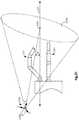
- FIG. 1illustrates, as an example, a top view of an operating room in which a medical robotic system 100 is being utilized by a Surgeon 20 for performing a medical procedure on a Patient 40 who is lying face up on an operating table 50.
- One or more Assistants 30may be positioned near the Patient 40 to assist in the procedure while the Surgeon 20 performs the procedure teleoperatively by manipulating input devices 108, 109 on a surgeon console 10.
- an entry guide (EG) 200is inserted through a single entry aperture 150 into the Patient 40.
- the entry aperture 150is a minimally invasive incision in the present example, in the performance of other medical procedures, it may instead be a natural body orifice.
- the entry guide 200is held and manipulated by a robotic arm assembly 130.
- the robotic arm assembly 130includes a setup arm and an entry guide manipulator.
- the setup armis used to position the entry guide 200 at the entry aperture 150 so that it properly enters the entry aperture 150.
- the entry guide manipulatoris then used to robotically insert and retract the entry guide 200 into and out of the entry aperture 150. It may also be used to robotically pivot the entry guide 200 in pitch, roll and yaw about a pivot point located at the entry aperture 150.
- An example of such an entry guide manipulatoris the entry guide manipulator 202 of FIG. 2 and an example of the four degrees-of-freedom movement that it manipulates the entry guide 200 with is shown in FIG. 5 .
- the console 10includes a 3-D monitor 104 for displaying a 3-D image of a surgical site to the Surgeon, left and right hand-manipulatable input devices 108, 109, and a processor (also referred to herein as a "controller") 102.
- the input devices 108, 109may include any one or more of a variety of input devices such as joysticks, gloves, trigger-guns, hand-operated controllers, or the like.
- Other input devices that are provided to allow the Surgeon to interact with the medical robotic system 100include a foot pedal 105, a conventional voice recognition system 160 and a Graphical User Interface (GUI) 170.
- GUIGraphical User Interface
- An auxiliary display screen 140is coupled to the console 10 (and processor 102 ) for providing auxiliary views to the Surgeon to supplement those shown on the monitor 104.
- a second auxiliary display screen 140'is also coupled to the console 10 (and processor 102 ) for providing auxiliary views to the Assistant(s).
- An input device 180is also coupled to the console to allow the Assistant(s) to select between available auxiliary views for display on the second auxiliary display screen 140'.
- the console 10is usually located in the same room as the Patient so that the Surgeon may directly monitor the procedure, is physically available if necessary, and is able to speak to the Assistant(s) directly rather than over the telephone or other communication medium.
- the console 10may be connected to the second auxiliary display screen 140' and input device 180 through a network connection such as a local area network, wide area network, or the Internet.
- the entry guide 200has articulatable instruments such as articulatable surgical tools 231, 241 and an articulatable stereo camera 211 extending out of its distal end. Although only two tools 231, 241 are shown, the entry guide 200 may guide additional tools as required for performing a medical procedure at a work site in the Patient. For example, as shown in FIG. 4 , a passage 351 is available for extending another articulatable surgical tool through the entry guide 200 and out through its distal end. Each of the surgical tools 231, 241 is associated with one of the input devices 108, 109 in a tool following mode.
- the Surgeonperforms a medical procedure by manipulating the input devices 108, 109 so that the controller 102 causes corresponding movement of their respectively associated surgical tools 231, 241 while the Surgeon views the work site in 3-D on the console monitor 104 as images of the work site are being captured by the articulatable camera 211.
- input devices 108, 109will be provided with at least the same degrees of freedom as their associated tools 231, 241 to provide the Surgeon with telepresence, or the perception that the input devices 108, 109 are integral with the tools 231, 241 so that the Surgeon has a strong sense of directly controlling the tools 231, 241.
- the monitor 104is also positioned near the Surgeon's hands so that it will display a projected image that is oriented so that the Surgeon feels that he or she is actually looking directly down onto the work site and images of the tools 231, 241 appear to be located substantially where the Surgeon's hands are located.
- the real-time image on the monitor 104is preferably projected into a perspective image such that the Surgeon can manipulate the end effectors 331, 341 of the tools 231, 241 through their corresponding input devices 108, 109 as if viewing the work site in substantially true presence.
- true presenceit is meant that the presentation of an image is a true perspective image simulating the viewpoint of an operator that is physically manipulating the end effectors 331, 341.
- the processor 102may transform the coordinates of the end effectors 331, 341 to a perceived position so that the perspective image being shown on the monitor 104 is the image that the Surgeon would see if the Surgeon was located directly behind the end effectors 331, 341.
- the processor 102performs various functions in the system 100.
- One important function that it performsis to translate and transfer the mechanical motion of input devices 108, 109 through control signals over bus 110 so that the Surgeon can effectively manipulate devices, such as the tools 231, 241, camera 211, and entry guide 200, that are selectively associated with the input devices 108, 109 at the time.
- Another functionis to perform various methods and controller functions described herein.
- processor 102may be implemented in practice by any combination of hardware, software and firmware. Also, its functions as described herein may be performed by one unit or divided up among different components, each of which may be implemented in turn by any combination of hardware, software and firmware. Further, although being shown as part of or being physically adjacent to the console 10, the processor 102 may also comprise a number of subunits distributed throughout the system.
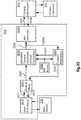
- FIG. 2illustrates, as an example, a block diagram of components for controlling and selectively associating device manipulators to the input devices 108, 109.
- Various surgical toolssuch as graspers, cutters, and needles may be used to perform a medical procedure at a work site within the Patient.
- two surgical tools 231, 241are used to robotically perform the procedure and the camera 211 is used to view the procedure.
- the tools 231, 241 and camera 211are inserted through passages in the entry guide 200.
- the entry guide 200is inserted into the Patient through entry aperture 150 using the setup portion of the robotic arm assembly 130 and maneuvered by the entry guide manipulator (EGM) 202 of the robotic arm assembly 130 towards the work site where the medical procedure is to be performed.
- EMMentry guide manipulator
- Each of the devices 231, 241, 211, 200is manipulated by its own manipulator.
- the camera 211is manipulated by a camera manipulator (ECM) 212
- the first surgical tool 231is manipulated by a first tool manipulator (PSM1) 232
- the second surgical tool 241is manipulated by a second tool manipulator (PSM2) 242
- the entry guide 200is manipulated by an entry guide manipulator (EGM) 202.
- ECMcamera manipulator
- the devices 231, 241, 211, 200are not shown, only their respective manipulators 232, 242, 212, 202 are shown in the figure.
- Each of the instrument manipulators 232, 242, 212is a mechanical assembly that carries actuators and provides a mechanical, sterile interface to transmit motion to its respective articulatable instrument.
- Each instrument 231, 241, 211is a mechanical assembly that receives the motion from its manipulator and, by means of a cable transmission, propagates the motion to its distal articulations (e.g., joints). Such joints may be prismatic (e.g., linear motion) or rotational (e.g., they pivot about a mechanical axis).
- the instrumentmay have internal mechanical constraints (e.g., cables, gearing, cams, belts, etc.) that force multiple joints to move together in a pre-determined fashion.
- Each set of mechanically constrained jointsimplements a specific axis of motion, and constraints may be devised to pair rotational joints (e.g., joggle joints). Note also that in this way the instrument may have more joints than the available actuators.
- the entry guide manipulator 202has a different construction and operation. A description of the parts and operation of the entry guide manipulator 202 is described below in reference to FIG. 7 .
- each of the input devices 108, 109may be selectively associated with one of the devices 211, 231, 241, 200 so that the associated device may be controlled by the input device through its controller and manipulator.
- the left and right input devices 108, 109may be respectively associated with the first and second surgical tools 231, 241, which are telerobotically controlled through their respective controllers 233, 243 (preferably implemented in the processor 102 ) and manipulators 232, 242 so that the Surgeon may perform a medical procedure on the Patient while the entry guide 200 is locked in place.
- either one or both of the left and right input devices 108, 109may be associated with the camera 211 or entry guide 200 so that the Surgeon may move the camera 211 or entry guide 200 through its respective controller ( 213 or 203 ) and manipulator ( 212 or 202 ).
- the disassociated one(s) of the surgical tools 231, 241is locked in place relative to the entry guide 200 by its controller.
- the left and right input devices 108, 109may be associated with the camera 211, which is telerobotically controlled through its controller 213 (preferably implemented in the processor 102 ) and manipulator 212 so that the Surgeon may position the camera 211 while the surgical tools 231, 241 and entry guide 200 are locked in place by their respective controllers 233, 243, 203. If only one input device is to be used for positioning the camera, then only one of the switches 258, 259 is placed in its camera positioning mode while the other one of the switches 258, 259 remains in its tool following mode so that its respective input device may continue to control its associated surgical tool.
- the left and right input devices 108, 109may be associated with the entry guide 200, which is telerobotically controlled through its controller 203 (preferably implemented in the processor 102 ) and manipulator 202 so that the Surgeon may position the entry guide 200 while the surgical tools 231, 241 and camera 211 are locked in place relative to the entry guide 200 by their respective controllers 233, 243, 213.
- the selective association of the input devices 108, 109 to other devices in this examplemay be performed by the Surgeon using the GUI 170 or the voice recognition system 160 in a conventional manner.
- the association of the input devices 108, 109may be changed by the Surgeon depressing a button on one of the input devices 108, 109 or depressing the foot pedal 105, or using any other well known mode switching technique.
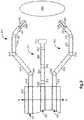
- FIGS. 3-4respectively illustrate, as examples, top and right side views of a distal end of the entry guide 200 with the camera 211 and surgical tools 231, 241 extending outward.
- the entry guide 200is generally cylindrical in shape and has a longitudinal axis X' running centrally along its length.
- the pivot pointwhich is also referred to as a remote center "RC" serves as an origin for both a fixed reference frame having X, Y and Z axes as shown and an entry guide reference frame having X', Y' and Z' axes as shown.
- the entry guide manipulator 202When the system 100 is in the entry guide positioning mode, the entry guide manipulator 202 is capable of pivoting the entry guide 200 in response to movement of one or more associated input devices about the Z axis (which remains fixed in space) at the remote center "RC" in yaw ⁇ .
- the entry guide manipulator 202is capable of pivoting the entry guide 200 in response to movement of the one or more input devices about the Y' axis (which is orthogonal to the longitudinal axis X' of the entry guide 200 ) in pitch ⁇ , capable of rotating the entry guide 200 about its longitudinal axis X' in roll ⁇ , and linearly moving the entry guide 200 along its longitudinal axis X' in insertion/retraction or in/out "I/O" directions in response to movement of the one or more associated input devices.
- the X' and Y' axesmove with the entry guide 200.
- the entry guide manipulator (EGM) 202has four actuators 701-704 for actuating the four degrees-of-freedom movement of the entry guide 200 (i.e., pitch ⁇ , yaw ⁇ , roll ⁇ , and in/out I/O) and four corresponding assemblies 711-714 to implement them.
- the articulatable camera 211extends through passage 321 and the articulatable surgical tools 231, 241 respectively extend through passages 431, 441 of the entry guide 200.
- the camera 211includes a tip 311 (which houses a stereo camera connected to a camera controller and a fiber-optic cable connected to an external light source), first, second, and third links 322, 324, 326, first and second joint assemblies (also referred to herein simply as "joints”) 323, 325, and a wrist assembly 327.
- the first joint assembly 323couples the first and second links 322, 324 and the second joint assembly 325 couples the second and third links 324, 326 so that the second link 324 may pivot about the first joint assembly 323 in pitch and yaw while the first and third links 322, 326 remain parallel to each other.
- the first and second joints 323, 325are referred to as “joggle joints", because they cooperatively operate together so that as the second link 324 pivots about the first joint 323 in pitch and/or yaw, the third link 326 pivots about the second joint 325 in a complementary fashion so that the first and third links 322, 326 always remain parallel to each other.
- the first link 322may also rotate around its longitudinal axis in roll as well as move in and out (e.g., insertion towards the work site and retraction from the worksite) through the passage 321.
- the wrist assembly 327also has pitch and yaw angular movement capability so that the camera's tip 311 may be oriented up or down and to the right or left, and combinations thereof.
- the joints and links of the tools 231, 241are similar in construction and operation to those of the camera 211.
- the tool 231includes an end effector 331 (having jaws 338, 339 ), first, second, and third links 332, 334, 336, first and second joint assemblies 333, 335, and a wrist assembly 337 that are driven by actuators such as described in reference to FIG. 8 (plus an additional actuator for actuating the end effector 331 ).
- the tool 241includes an end effector 341 (having jaws 348, 349 ), first, second, and third links 342, 344, 346, first and second joint assemblies 343,345, and a wrist assembly 347 that are also driven by actuators such as described in reference to FIG. 8 (plus an additional actuator for actuating the end effector 341 ).
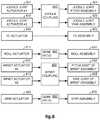
- FIG. 8illustrates, as an example, a diagram of interacting parts of an articulatable instrument (such as the articulatable camera 211 and the articulatable surgical tools 231, 241 ) and its corresponding instrument manipulator (such as the camera manipulator 212 and the tool manipulators 232, 242 ).
- Each of the instrumentsincludes a number of actuatable assemblies 821-823, 831-833, 870 for effectuating articulation of the instrument (including its end effector), and its corresponding manipulator includes a number of actuators 801-803, 811-813, 860 for actuating the actuatable assemblies.
- pitch/yaw coupling mechanisms 840, 850(respectively for the joggle joint pitch/yaw and the wrist pitch/yaw) and gear ratios 845, 855 (respectively for the instrument roll and the end effector actuation) are provided in a sterile manipulator/instrument interface to achieve the required range of motion of the instrument joints in instrument joint space while both satisfying compactness constraints in the manipulator actuator space and preserving accurate transmissions of motion across the interface.
- the coupling between the joggle joint actuators 801, 802 (differentiated as #1 and #2) and joggle joint pitch/yaw assemblies 821, 822may include a pair of coupling mechanisms - one on each side of the sterile interface (i.e., one on the manipulator side of the interface and one on the instrument side of the interface).
- the coupling between the wrist actuators 812, 813 (differentiated as #1 and #2) and wrist pitch/yaw joint assemblies 832, 833may also comprise a pair of coupling mechanisms - one on each side of the sterile interface.
- Both the joggle joint pitch assembly 821 and the joggle joint yaw assembly 822share the first, second and third links (e.g., links 322, 324, 326 of the articulatable camera 211 ) and the first and second joints (e.g., joints 322, 325 of the articulatable camera 211 ).
- first, second and third linkse.g., links 322, 324, 326 of the articulatable camera 211
- first and second jointse.g., joints 322, 325 of the articulatable camera 211
- the joggle joint pitch and yaw assemblies 821, 822also include mechanical couplings that couple the first and second joints (through joggle coupling 840 ) to the joggle joint pitch and yaw actuators 801, 802 so that the second link may controllably pivot about a line passing through the first joint and along an axis that is latitudinal to the longitudinal axis of the first link (e.g., link 322 of the articulatable camera 211 ) and the second link may controllably pivot about a line passing through the first joint and along an axis that is orthogonal to both the latitudinal and longitudinal axes of the first link.
- the second linkmay controllably pivot about a line passing through the first joint and along an axis that is orthogonal to both the latitudinal and longitudinal axes of the first link.
- the in/out (I/O) assembly 823includes the first link (e.g., link 322 of the articulatable camera 211 ) and interfaces through a drive train coupling the in/out (I/O) actuator 803 to the first link so that the first link is controllably moved linearly along its longitudinal axis by actuation of the I/O actuator 803.
- the roll assembly 831includes the first link and interfaces through one or more gears (i.e., having the gear ratio 845 ) that couple a rotating element of the roll actuator 811 (such as a rotor of a motor) to the first link so that the first link is controllably rotated about its longitudinal axis by actuation of the roll actuator 811.
- the instrument manipulator(e.g., camera manipulator 212) includes wrist actuators 812, 813 that actuate through wrist coupling 850 pitch and yaw joints 832, 833 of the wrist assembly (e.g., wrist 327 of the articulatable camera 211 ) so as to cause the instrument tip (e.g., camera tip 311 ) to controllably pivot in an up-down (i.e., pitch) and side-to-side (i.e., yaw) directions relative to the wrist assembly.
- wrist actuators 812, 813that actuate through wrist coupling 850 pitch and yaw joints 832, 833 of the wrist assembly (e.g., wrist 327 of the articulatable camera 211 ) so as to cause the instrument tip (e.g., camera tip 311 ) to controllably pivot in an up-down (i.e., pitch) and side-to-side (i.e., yaw) directions relative to the wrist assembly.
- the grip assembly 870includes the end effector (e.g., end effector 331 of the surgical tool 231 ) and interfaces through one or more gears (i.e., having the gear ratio 855) that couple the grip actuator 860 to the end effector so as to controllably actuate the end effector.
- the end effectore.g., end effector 331 of the surgical tool 231
- gearsi.e., having the gear ratio 855
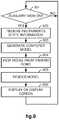
- FIG. 9illustrates, as an example, a flow diagram of a method implemented in controller 102 of the medical robotic system 100 for providing a computer generated auxiliary view including articulatable instruments, such as the articulatable camera 211 and/or one or more of the articulatable surgical tools 231, 241, extending out of the distal end of the entry guide 200.
- articulatable instrumentssuch as the articulatable camera 211 and/or one or more of the articulatable surgical tools 231, 241, extending out of the distal end of the entry guide 200.
- the articulatable camera 211 and surgical tools 231, 241extend out of the distal end of the entry guide 200 and are included in the auxiliary view.
- the methodis applicable to any combination of articulatable instruments, including those without an articulatable camera and/or those with an alternative type of image capturing device such as an ultrasound probe.
- the methoddetermines whether or not an auxiliary view is to be generated. If the determination in 901 is NO, then the method loops back to periodically check to see whether the situation has changed. On the other hand, if the determination in 901 is YES, then the method proceeds to 902.
- the indication that an auxiliary view is to be generatedmay be programmed into the controller 102, created automatically or created by operator command.
- the methodreceives state information, such as positions and orientations, for each of the instruments 211, 231, 241 and the entry guide 200.
- This informationmay be provided by encoders coupled to the actuators in their respective manipulators 212, 232, 242, 202.
- the informationmay be provided by sensors coupled to joints and/or links of the instruments 211, 231, 241 and the entry guide manipulator 202, or the coupling mechanisms, gears and drive trains of the interface between corresponding manipulators and instruments, so as to measure their movement.
- the sensorsmay be included in the instruments 211, 231, 241 and entry guide manipulator 202 such as rotation sensors that sense rotational movement of rotary joints and linear sensors that sense linear movement of prismatic joints in the instruments 211, 231, 241 and entry guide manipulator 202.
- Other sensorsmay also be used for providing information of the positions and orientations of the instruments 211, 231, 241 and entry guide 200 such as external sensors that sense and track trackable elements, which may be active elements (e.g., radio frequency, electromagnetic, etc.) or passive elements (e.g., magnetic, etc.), placed at strategic points on the instruments 211, 231, 241, the entry guide 200 and/or the entry guide manipulator 202 (such as on their joints, links and/or tips).
- active elementse.g., radio frequency, electromagnetic, etc.
- passive elementse.g., magnetic, etc.
- the methodgenerates a three-dimensional computer model of the articulatable camera 211 and articulatable surgical tools 231, 241 extending out of the distal end of the entry guide 200 using the information received in 902 and the forward kinematics and known constructions of the instruments 211, 231, 241, entry guide 200, and entry guide manipulator 202.
- the generated computer model in this examplemay be referenced to the remote center reference frame (X, Y, Z axes) depicted in FIG. 5 .
- the generated computer modelmay be referenced to a reference frame defined at the distal end of the entry guide 200. In this latter case, if the orientation and extension of the entry guide 200 from the remote center does not have to be accounted for in the auxiliary view that is being generated by the method, then the position and orientation information for the entry guide 200 may be omitted in 902.
- the state information received in 902is the instruments' joint positions 1001
- this informationmay be applied to the instruments' forward kinematics 1002 using the instruments' kinematic models 1003 to generate the instruments' link positions and orientations 1005 relative to reference frame 1004.
- the same processmay also be generally applied if the state information received in 902 is sensed states of the joggle coupling and gear mechanisms in the manipulator/instrument interfaces.
- the state information received in 902is the instruments' tip positions 1101 (in the reference frame 1004 )
- this informationmay be applied to the instruments' inverse kinematics 1102 using the instruments' kinematic models 1003 and the sensor reference frame to generate the instruments' joint positions 1001.
- the instruments' joint positions 1001may then be applied as described in reference to FIG. 10 to generate the instruments' link positions and orientations 1005 relative to reference frame 1004.
- the positions of the tips of the surgical tools 231, 241may be determined relative to the camera reference frame by identifying the tips in the image captured by the camera 211 using conventional image processing techniques and then translating their positions to the reference frame 1004, so that the positions of the camera and tool tips may be applied as described in reference to FIGS. 10, 11 to generate the instruments' link positions and orientations 1005 relative to the reference frame 1004.
- the methodadjusts the view of the computer model of the articulatable camera 211 and articulatable surgical tools 231, 241 extending out of the distal end of the entry guide 200 in the three-dimensional space of the reference frame to a specified viewing point (wherein the term "viewing point” is to be understood herein to include position and orientation).
- FIG. 12illustrates a top view of the articulatable camera 211 and articulatable surgical tools 231, 241 extending out of the distal end of the entry guide 200 which corresponds to a viewing point above and slightly behind the distal end of the entry guide 200.
- FIG. 12illustrates a top view of the articulatable camera 211 and articulatable surgical tools 231, 241 extending out of the distal end of the entry guide 200 which corresponds to a viewing point above and slightly behind the distal end of the entry guide 200.
- FIG. 12illustrates a top view of the articulatable camera 211 and articulatable surgical tools 231, 241 extending out of the distal end of the
- FIGS. 12-13illustrates a side view of the articulatable camera 211 and articulatable surgical tools 231, 241 extending out of the distal end of the entry guide 200 which corresponds to a viewing point to the right and slightly in front of the distal end of the entry guide 200.
- the auxiliary views depicted in FIGS. 12-13are two-dimensional, they may also be three-dimensional views since three-dimensional information is available from the generated computer model. In this latter case, the auxiliary display screen 140 that they are being displayed on would have to be a three-dimensional display screen like the monitor 104.
- the viewing pointmay be set at a fixed point such as one providing an isometric (three-dimensional) view from the perspective shown in FIG. 12 .
- This perspectiveprovides a clear view to the surgeon of the articulatable camera 211 and the articulatable surgical tools 231, 241 when the tools 231, 241 are bent "elbows out” as shown (which is a typical configuration for performing a medical procedure using the surgical tools 231, 241 ).
- a third surgical toolis being used (e.g., inserted in the passage 351 shown in FIG. 6 )
- a side view from the perspective of FIG. 13may additionally be useful since the third surgical tool may be beneath the articulatable camera 211 and therefore obscured by it in the perspective shown in FIG. 12 .
- the viewing pointmay also be automatically changed depending upon the control mode (i.e., one of the modes described in reference to FIG. 2 ) that is operative at the time.
- FIG. 18illustrates a method for automatically changing the auxiliary viewing mode depending upon the control. mode currently operative in the medical robotic system 100.
- a first auxiliary viewing modeis performed in 1802 when the medical robotic system 100 is determined in 1801 to be in a tool following mode
- a second auxiliary viewing modeis performed in 1804 when the medical robotic system 100 is determined in 1803 to be in an entry guide positioning mode
- a third auxiliary viewing modeis performed in 1806 when the medical robotic system 100 is determined in 1805 to be in a camera positioning mode.
- the viewing modes for each control modeare selected so as to be most beneficial to the surgeon for performing actions during that mode.
- the entry guide positioning modethe articulatable camera 211 and the articulatable surgical tools 231, 241 are locked in position relative to the entry guide 200 and therefore, an auxiliary view providing information on other things such as depicted in FIGS. 16 and 17 may be useful.
- GUI 170 or voice recognition system 160may be adapted to provide an interactive means for the Surgeon to select the viewing mode and/or change the viewing point of an auxiliary view of the articulatable camera 211 and/or articulatable surgical tools 231, 241 as they extend out of the distal end of the entry guide 200.
- Buttons on the input devices 108, 109 or the foot pedal 105may also be used for Surgeon selection of viewing modes.
- the input device 180may be used along with a GUI associated with the display screen 140' for selection of viewing modes.
- the viewing modes that the Surgeon and Assistant(s) see at the timemay be optimized for their particular tasks at the time. Examples of such operator selectable viewing modes and viewing angles are depicted in FIGS. 12-17 .
- the methodrenders the computer model.
- Renderingin this case includes adding three-dimensional qualities such as known construction features of the instruments 211, 231, 241 and the distal end of the entry guide 200 to the model, filling-in any gaps to make solid models, and providing natural coloring and shading.
- renderingmay include altering the color or intensity of one or more of the instruments 211, 231, 241 (or one or more of their joints or links or portions thereof) so that the instrument (or joint or link or portion thereof) stands out for identification purposes.
- the altering of the color, intensity, or frequency of blinking on and off (e.g., flashing) of one or more of the instruments 211, 231, 241 (or their joints, links, or portions thereof)may serve as a warning that the instrument (or joint or link or portion thereof) is approaching an undesirable event or condition such as nearing a limit of its range of motion or getting too close to or colliding with another one of the instruments.
- the colormay go from a first color (e.g., green) to a second color (e.g., yellow) when a warning threshold of an event to be avoided (e.g., range of motion limitation or collision) is reached, and from the second color to a third color (e.g., red) when the event to be avoided is reached.
- a warning threshold of an event to be avoidede.g., range of motion limitation or collision
- a third colore.g., red
- intensitywhen intensity is used as a warning, the intensity of the color changes as the instrument (or portion thereof) moves past the warning threshold towards the event to be avoided with a maximum intensity provided when the event is reached.
- blinking of the coloris used as a warning
- the frequency of blinkingchanges as the instrument (or portion thereof) moves past the warning threshold towards the event to be avoided with a maximum frequency provided when the event is reached.
- the warning thresholdmay be based upon a range of motion of the instrument (or portion thereof, such as its joints) or upon a distance between the instrument (or portion thereof) and another instrument (or portion thereof) that it may collide with. Velocity of the instrument's movement may also be a factor in determining the warning threshold.
- the warning thresholdmay be programmed by the operator, using the GUI 170 , for example, or determined automatically by a programmed algorithm in the processor 102 that takes into account other factors such as the velocity of the instruments' movements.
- the altering of the color, intensity, or frequency of blinking on and off (e.g., flashing) of one or more of the instruments 211 , 231 , 241 (or their joints, links, or portions thereof)may serve as an alert that the instrument (or joint or link or portion thereof) is approaching a desirable event or condition such as an optimal position or configuration for performing or viewing a medical procedure.
- an alert thresholdmay be defined so that the color, intensity, and/or blinking of the one or more of the instruments 211 , 231 , 241 (or their joints, links, or portions thereof) may change in a similar manner as described previously with respect to warning thresholds and undesirable events or conditions, except that in this case, the change starts when the alert threshold is reached and maximizes or otherwise ends when the desirable event or condition is reached or otherwise achieved.
- the alert thresholdmay also be programmed by the operator or determined automatically by a programmed algorithm in a conceptually similar manner as the warning threshold.
- FIG. 15shows an auxiliary view of the camera 211 and surgical tools 231 , 241 in a window 1502 , where the camera 211 has been highlighted.
- FIG. 12shows joints of the surgical tools 231, 241 that have been highlighted.
- FIG. 14shows a portion 1402 of the surgical tool 241 and a portion 1403 of the camera 211 highlighted to indicate that these portions are dangerously close to colliding.
- Renderingmay also include overlaying the image captured by the camera 211 over the auxiliary view when the viewing point of the auxiliary image is the same as or directly behind that of the camera 211.
- FIG. 17illustrates a captured image 1700 of the camera 211 rendered as an overlay to an auxiliary view of surgical tools 231, 241 which has been generated from a viewing point of (or right behind) the camera 211.
- the auxiliary view of the surgical tools 231, 241 being displayed on the auxiliary display screen 140 (and/or the auxiliary display screen 140' )includes portions (e.g., 1731 , 1741 ) in the overlaying captured image 1700 and portions (e.g., 1732 , 1742 ) outside of the overlaying captured image 1700.
- the portions of the surgical tools 231 , 241 outside of the captured image 1700provide the Surgeon with additional information about their respective links or articulating arms that are out of the field of view of the camera 211.
- Highlighting of the instrument portions (e.g., 1732 , 1742 ) outside of the captured image 1700may also be done for identification purposes or to indicate a warning or alerting condition as described above.
- Overlaying the captured image 1700 onto the auxiliary viewalso has the advantage in this case of showing an anatomic structure 360 which is in front of the surgical tools 231 , 241 that would not otherwise normally be in the auxiliary view.
- this exampleshows the captured image 1700 overlaying the auxiliary view on the auxiliary display screen 140 , in another rendering scheme, the auxiliary view may overlay the captured image that is being displayed on the monitor 104.
- renderingmay also include using the auxiliary view to augment the image captured by the camera 211 by displaying only the portions of the instruments 231, 241 that are not seen in the captured image (i.e., the dotted line portion of the instruments 231 , 241 in FIG. 17 ) in proper alignment and adjacent the captured image in a mosaic fashion.
- renderingmay also include providing other useful information in the auxiliary view.
- FIG. 16illustrates an auxiliary side view of an articulatable camera 211 with a frustum 1601 rendered on the auxiliary view so as to be displayed on the auxiliary display 140 as emanating from, and moving with, the camera tip 311.
- the frustum 1601is shown in the figure as a truncated cone, it may also appear as a truncated pyramid to correspond to the captured image that is shown on the monitor 104.
- FIG. 14shows a semi-translucent sphere or bubble 1401 (preferably colored red) which is displayed by the method as part of the rendering process when a warning threshold is reached so as to indicate to the operator that the highlighted portions 1402 , 1403 of the surgical tool 241 and camera 211 are dangerously close to colliding.
- the highlighted portions 1402 , 1403are preferably centered within the sphere.
- the 14also shows a marker or other indicator 1410 indicating an optimal position for the camera tip 311 for viewing the end effectors of the surgical tools 231 , 241 as they are being used to perform a medical procedure.
- the optimal positionmay be determined, for example, by finding a location where the tips of the end effectors are equidistant from a center of the captured image.
- the methodcauses the rendered computer model (i.e., the auxiliary view) to be displayed on one or more displayed screens (e.g., 140 and 140' ) from the perspective of the selected viewing point.
- the auxiliary viewis displayed on the auxiliary display screen 140.
- more than one auxiliary viewmay be displayed at one time (e.g., top and side perspectives may be provided at the same time respectively in windows 1421 and 1422).
- the auxiliary viewmay also be displayed on the primary monitor 104 in a window 1502 that is adjacent to an image captured by the articulatable camera 211 which is being shown in another window 1501.
- the windows 1501 and 1502appear in this example to be the same size, it is to be appreciated that the position and size of the auxiliary view window 1502 may vary and still be within the scope of the present invention.
- the auxiliary viewmay be overlayed the captured image in the window 1501 instead of in its own separate window 1502.
- the overlayed auxiliary viewmay be switched on and off by the Surgeon so as not to clutter the captured image during the performance of a medical procedure.
- the switching on and off in this casemay be performed by depressing a button on one of the input devices 108 , 109 or depressing the foot pedal 105.
- voice activationusing the voice recognition system 160 or through Surgeon interaction with the GUI 170 or using any other conventional function switching means.
- the methodAfter completing 906 , the method then loops back to 901 to repeat 901-906 for the next processing cycle of the controller 102.
- one or both of the input devices 108 , 109may be used to do so by temporarily associating it/them with the camera manipulator 212.
- One way that the Surgeon may perform such repositioningis for him or her to view images on the 3-D monitor 104 that were captured by the stereoscopic camera in the camera tip 311 , such as the image shown in window 1501 of FIG. 15 , and use the captured images to guide his or her manipulation of the input device.
- image referenced controlThis type of camera control is referred to as "image referenced control" since the Surgeon uses the image captured by the camera 211 as a reference for his or her controlling of the camera movement (i.e., the motion of the input device 108 corresponds to the motion of the camera tip 311 with respect to the captured image).
- image referenced controlmay be useful when the Surgeon is fine tuning the position and/or orientation of the camera tip 311 , for larger movements problems may occur as a result of unintentional collisions between instrument links outside the field of view of the camera 211.
- an “instrument referenced control”may be more desirable where an auxiliary image of the camera 211 and tools 231, 241 extending out of the distal end of the entry guide 200 , such as shown in window 1502 of FIG. 15 , may be preferable for guiding the Surgeon's manipulation of the input device (i.e., the motion of the input device 108 corresponds to the motion of the camera tip 311 with respect to the auxiliary image).
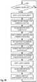
- FIG. 19illustrates, as an example of "instrument referenced control", a flow diagram of a method implemented in the medical robotic system 100 for positioning and orienting the tip 311 of the articulatable camera instrument 211 in response to operator manipulation of the input device 108 (in camera positioning mode) while the operator views a computer generated auxiliary view of the camera 211 on either the display screen 140 or the console monitor 104.
- both input devices 108 , 109may be used for positioning and orienting the camera 211, such as a bicycle "handlebar" type control
- the present exampleassumes that only one input device 108 (also referred to herein as the "master” or “master manipulator”) is used so that the other input device 109 may still be associated with and control its tool 231.
- the methodperiodically loops back (e.g., at each processing cycle or a programmable multiple of a processing cycle) to check the current status of the switch 258. On the other hand, if the determination in 1901 is YES, then the method performs preparatory tasks 1902-1906 before enabling control over the positioning and orienting of the camera tip 311 by the input device 108 in 1907.
- the other medical devices 241 , 200 associated with the input device 108are soft-locked so that they are commanded to remain in their present stationary state by their controllers 242 , 202.
- the methodcomputes the reference frame which is used for control purposes (the "control reference frame”).
- This reference frameis necessary to map between the Cartesian motion of the master 108 and the Cartesian motion of the camera tip 311.
- the reference frameis preferably fixed in space during camera positioning mode for ease of computation.
- a reference frame defined by the camera tip 311such as in tool following mode, is not desirable in camera positioning mode because in camera positioning mode, the camera tip 311 is moving and therefore, even though its state is determinable, its pose is not clearly perceivable by the Surgeon. Therefore, the Surgeon may find it more difficult in this situation to position the camera tip 311 at the desired location with respect to the Patient's anatomy using the master 108.
- FIG. 20illustrates a so-called "zero position" reference frame 2002 which corresponds to the position and orientation where the joints 323 , 325 , 327 are rotated so that the links 321 , 324 , 326 are in a straight line and their insertion position is a fully retracted position (i.e., the camera tip 311 is just inside the passage 321 of the entry guide 200 ).
- a reference frame defined at the camera tipi.e., the camera reference frame 2010
- This framehas the property of being aligned with the entry guide 200 and is centered with respect to the workspace of the camera tip 311.
- the range of motion limits(perceived by the operator through haptic feedback on the input device 108 ) can be used to find the center position of the camera tip 311 and the operator can easily understand how the camera instrument 211 moves in response to the motions of his or her arm/hand.
- the kinesthetic mapping between user arm/hand and camera tip 311is aligned to the visual mapping between the camera motion and the auxiliary view seen by the Surgeon at the console 104 and/or auxiliary display 140.
- FIG. 21illustrates an "isometric auxiliary view" reference frame 2102 which corresponds to a viewing point of the auxiliary view being displayed on the auxiliary display 140 (such as shown in FIG. 12 ) and/or monitor 104 (such as shown in window 1502 of FIG. 15 ).
- the viewing pointin this case may be thought of as a view taken from the perspective of a virtual camera 2103 whose position and orientation is preferably fixed in space during the camera positioning mode.
- the reference frame 2102is defined at the tip (i.e., viewing end) of the virtual camera 2103 and its position and orientation are computed so that it has an azimuth angle ⁇ with respect to a focal point 2104 (of the virtual camera 2103 ) on the central longitudinal axis 2101 of the passage 321 of the entry guide 200 through which the camera instrument 211 extends.
- the location of the focal point 2104 along the longitudinal axis 2101 and the size of the azimuth angle ⁇are selected so that the virtual camera 2103 has a slight elevation that provides adequate depth perception in the isometric rendering of the auxiliary view and its field of view 2106 includes the links of the camera instrument 211 and surgical tool 231 during the camera positioning mode.
- the orientation of a hand-grippable part of the input device 108(referred to herein as the masterorientation") is aligned so that the master orientation with respect to the auxiliary view being displayed on the 3-D monitor 104 is the same as the current orientation of the camera tip 311 with respect to the reference frame computed in 1903 for camera control.
- this orientation alignmentmay be avoided by, for example, computing and accounting for the offset between the current master orientation and the current camera orientation so that the master angular motions with respect to the initial orientation are used to command the movement of the camera tip 311.
- the current position of the hand-grippable part of the input device 108is mapped to the current position of the camera tip 311 so as to cancel translational offsets, and in 1906 , user-selectable scaling factors are set between the input device 108 and the camera 211 workspaces.
- the camera controller (CTRLC) 213is enabled so that the input device 108 now controls the positioning and orienting of the articulatable camera instrument 211 through the camera controller (CTRLC) 213 and manipulator (ECM) 212 , and in 1908, the camera tip 311 is moved to the desired position and/or orientation.
- CTRLCcamera controller
- ECMmanipulator
- the methodperforms preparatory tasks 1909-1910 before enabling control over the tool 241 by the input device 108 in 1911.
- the camera 211is soft-locked so that it is commanded to remain in its present stationary state (i.e., the desired position and/or orientation) by the camera controller 213 , and in 1910 , the master orientation is aligned with that of the tool 241.
- FIG. 22illustrates, as an example, a block diagram of the camera controller (CTRLC) 213 for controlling movement of the camera manipulator (ECM) 212 (also referred to herein as “slave manipulator” or “slave”) and consequently, the position and orientation of the tip 311 of the camera instrument 211, as commanded by movement of the input device 108 (also referred to herein as “master manipulator” or “master”) by the Surgeon.
- CTRLCcamera controller
- the input device 108includes a number of links connected by joints so as to facilitate multiple degrees-of-freedom movement. For example, as the Surgeon moves the input device 108 from one position to another, sensors associated with the joints of the input device 108 sense such movement at sampling intervals (appropriate for the processing speed of the controller 102 and camera control purposes) and provide digital information indicating such sampled movement in joint space to input processing block 2210.
- Input processing block 2210processes the information received from the joint sensors of the input device 108 to transform the information into a corresponding desired position and velocity for the camera tip 311 in its Cartesian space relative to a reference frame associated with the position of the Surgeon's eyes (the "eye reference frame") by computing a joint velocity from the joint position information and performing the transformation using a Jacobian matrix and eye related information using well-known transformation techniques.
- Scale and offset processing blocks 2201receives the processed information 2211 from the input processing block 2210 and applies scale and offset adjustments to the information so that the resulting movement of the camera tip 311 and consequently, its computer generated auxiliary view being viewed by the Surgeon at the time on the monitor 104 and/or auxiliary display 140 appears natural and as expected by the Surgeon.
- the scale adjustmentis useful where small movements of the camera tip 311 are desired relative to larger movement of the input device 108 in order to allow more precise movement of the camera tip 311 as it views the work site.
- An offset adjustmentis applied for aligning the input device 108 with respect to the Surgeon's eyes as he or she manipulates the input device 108 to command movement of the camera tip 311 through the auxiliary view that is being displayed at the time on the monitor 104 and/or auxiliary display 140.
- a simulated camera block 2204receives the output 2221 of the scale and offset processing block 2201 and transforms the commanded position and velocity for the camera tip 311 from the Cartesian space of the eye reference frame to the joint space of the camera manipulator 212 using its inverse kinematics while avoiding singularities in its operation and limiting the commanded joint positions and velocities to avoid physical limitations or other constraints such as avoiding harmful contact with tissue or other parts of the Patient.
- a mappingis performed between the eye frame and the control reference frame (provided by the reference frame computation block 2250 ) and another mapping is performed between a tip of the hand-grippable part of the master 108 and the camera tip 311.
- mappingspreserve orientations while offsets are compensated for in the scale and offset block 2201.
- the inverse and forward kinematics blocks 2204 , 2206use this information to perform their computations since the mappings describe the positions and orientations of the master and camera tips with respect to the control reference frame.
- the output 2224 of the simulated camera block 2204is then provided to a joint controller block 2205 and a forward kinematics block 2206.
- the joint controller block 2205includes a joint control system for each controlled joint (or operatively coupled joints such as "joggle joints") of the camera instrument 211 (such as translational and orientational assemblies shown and described in reference to FIG. 8 ).
- the output 2224 of the simulated camera block 2204provides the commanded value for each joint of the camera instrument 211.
- sensors associated with each of the controlled joints of the camera instrument 211provide sensor data 2232 back to the joint controller block 2205 indicating the current position and/or velocity of each joint of the camera instrument 211.
- the sensorsmay sense this joint information either directly (e.g., from the joint on the camera instrument 211 ) or indirectly (e.g., from the actuator in the camera manipulator 212 driving the joint).
- Each joint control system in the joint controller 2205then generates torque commands for its respective actuator in the camera manipulator 212 so as to drive the difference between the commanded and sensed joint values to zero in a conventional feedback control system manner.
- the forward kinematics block 2206transforms the output 2224 of the simulated camera block 2204 from joint space back to Cartesian space relative to the eye reference frame using the forward kinematics of the camera instrument 211 with respect to the control reference frame (provided by the reference frame computation block 2250 ).
- the scale and offset block 2201performs an inverse scale and offset function on the output 2242 of the forward kinematics block 2206 before passing its output 2212 to the input processing block 2210 where an error value is calculated between its output 2211 and input 2212. If no limitation or other constraint had been imposed on the input 2221 to the simulated camera block 2204 , then the calculated error value would be zero.
- the error valueis not zero and it is converted to a torque command that drives actuators in the input device 108 to provide force feedback felt by the hands of the Surgeon.
- the Surgeonbecomes aware that a limitation or constraint is being imposed by the force that he or she feels resisting his or her movement of the input device 108 in that direction.
- forces coming from other sensors or algorithmse.g., a force/pressure sensor or an algorithm to avoid the work volume of the surgical tools to prevent collisions may be superimposed on the force feedback.
- An output 2241 of the forward kinematics block 2206may also be provided to the simulated camera block 2204 for control purposes.
- the simulated position outputmay be fed back and compared with the commanded position.
Landscapes
- Health & Medical Sciences (AREA)
- Life Sciences & Earth Sciences (AREA)
- Engineering & Computer Science (AREA)
- Surgery (AREA)
- General Health & Medical Sciences (AREA)
- Medical Informatics (AREA)
- Animal Behavior & Ethology (AREA)
- Biomedical Technology (AREA)
- Public Health (AREA)
- Veterinary Medicine (AREA)
- Heart & Thoracic Surgery (AREA)
- Molecular Biology (AREA)
- Nuclear Medicine, Radiotherapy & Molecular Imaging (AREA)
- Physics & Mathematics (AREA)
- Pathology (AREA)
- Radiology & Medical Imaging (AREA)
- Biophysics (AREA)
- Optics & Photonics (AREA)
- Robotics (AREA)
- General Physics & Mathematics (AREA)
- Theoretical Computer Science (AREA)
- Mechanical Engineering (AREA)
- Signal Processing (AREA)
- Oral & Maxillofacial Surgery (AREA)
- Computer Vision & Pattern Recognition (AREA)
- Human Computer Interaction (AREA)
- Pulmonology (AREA)
- Chemical & Material Sciences (AREA)
- Mathematical Analysis (AREA)
- Business, Economics & Management (AREA)
- Educational Administration (AREA)
- Educational Technology (AREA)
- Medicinal Chemistry (AREA)
- Computational Mathematics (AREA)
- Mathematical Physics (AREA)
- Mathematical Optimization (AREA)
- Pure & Applied Mathematics (AREA)
- Algebra (AREA)
- Otolaryngology (AREA)
- Multimedia (AREA)
Description
- The present invention generally relates to medical robotic systems and in particular, to a medical robotic system providing computer generated auxiliary views of a camera instrument for controlling the positioning and orienting of its tip.
- Medical robotic systems such as systems used in performing minimally invasive surgical procedures offer many benefits over traditional open surgery techniques, including less pain, shorter hospital stays, quicker return to normal activities, minimal scarring, reduced recovery time, and less injury to tissue. Consequently, demand for such medical robotic systems is strong and growing.
- One example of such a medical robotic system is the da Vinci® Surgical System from Intuitive Surgical, Inc., of Sunnyvale, California, which is a minimally invasive robotic surgical system. The da Vinci® Surgical System has a number of robotic arms that move attached medical devices, such as an image capturing device and Intuitive Surgical's proprietary EndoWrist® articulating surgical instruments, in response to movement of input devices by a surgeon viewing images captured by the image capturing device of a surgical site. Each of the medical devices is inserted through its own minimally invasive incision into the patient and positioned to perform a medical procedure at the surgical site. The incisions are placed about the patient's body so that the surgical instruments may be used to cooperatively perform the medical procedure and the image capturing device may view it without their robotic arms colliding during the procedure.
- To perform certain medical procedures, it may be advantageous to use a single entry aperture, such as a minimally invasive incision or a natural body orifice, to enter a patient to perform a medical procedure. For example, an entry guide may first be inserted, positioned, and held in place in the entry aperture. Instruments such as an articulatable camera and a plurality of articulatable surgical tools, which are used to perform the medical procedure, may then be inserted into a proximal end of the entry guide so as to extend out of its distal end. Thus, the entry guide provides a single entry aperture for multiple instruments while keeping the instruments bundled together as it guides them toward the work site.
- Since the entry guide generally has a relatively small diameter in order to fit through a minimally invasive incision or a natural body orifice, a number of problems may arise while teleoperating the surgical tools to perform the medical procedure and the camera to view it. For example, because the camera instrument is bundled with the surgical tools, it is limited in its positioning relative to the surgical tools and consequently, its view of the surgical tools.
- Thus, although the tips of the articulatable surgical tools may be kept in the field of view of the camera, links coupled by controllable joints which facilitate the articulatability of the surgical tools may not be in the field of view of the camera. As a consequence, the links of the surgical tools may inadvertently collide with each other (or with a link of the camera instrument) during the performance of a medical procedure and as a result, cause harm to the patient or otherwise adversely impact the performance of the medical procedure.
- Also, since the articulatable camera instrument is generally incapable of viewing its own controllable linkage, operator movement of the camera tip is especially a concern where collisions with the surgical tool links are to be avoided. Further, when intuitive control is provided to assist the operator in teleoperatively moving the surgical tools and camera, the motions of the linkages required to produce such intuitive motions of the tips of the tools and camera may not be obvious or intuitive to the operator, thus making it even more difficult for the operator to avoid collisions between links that are outside the field of view of the camera.
WO 2008/103383 A1 discloses a medical robotic system which presents a surgeon with a video compilation that displays an endoscopic-camera derived image, a reconstructed view of the surgical field (including fiducial markers indicative of anatomical locations on or in the patient), and/or a real-time video image of the patient. The real-time image can be obtained either with the video camera that is part of the image localized endoscope or with an image localized video camera without an endoscope, or both. In certain other embodiments, the methods include the use of anatomical atlases related to pre-operative generated images derived from three-dimensional reconstructed CT, MRI, x-ray, or fluoroscopy. Images can furthermore be obtained from pre-operative imaging and spacial shifting of anatomical structures may be identified by intraoperative imaging and appropriate correction performed.- The present invention provides a medical robotic system as set out in the appended claims. Also described is a method implemented in a medical robotic system that provides a computer generated auxiliary view of a camera for positioning and orienting the camera.
- Also described is a method implemented in a medical robotic system that provides intuitive control to an operator controlling the positioning and orienting of a camera while viewing an auxiliary view of the camera.
- Also described is a method implemented in a medical robotic system that improves an operator's understanding of the configuration of linkages of articulatable instruments that are outside of the field of view of a camera while controllably positioning and orienting the camera.
- Also described is a method for positioning and orienting a camera tip (i.e., the viewing or image capturing end of the camera), the method comprising: determining positions of mechanical elements used for positioning and orienting the camera tip; determining a position and orientation of the camera tip using the determined positions of the mechanical elements; generating a view of a computer model of the camera corresponding to a perspective of a virtual camera; displaying the view on a display screen; and controlling the positioning and orienting of the camera tip by moving the mechanical elements in response to manipulation of an input device so that the positioning and orienting of the camera tip intuitively appears to an operator who is manipulating the input device while viewing the display screen to correspond to the displayed view of the computer model of the camera.
- The present invention provides a medical robotic system having a camera, mechanical elements used for positioning and orienting a camera tip of the camera, a display screen, and an input device, the medical robotic system characterized by: a controller configured to determine positions of the mechanical elements, determine a position and orientation of the camera tip using the determined positions of the mechanical elements, generate an auxiliary view of a computer model of the camera corresponding to a perspective of a virtual camera, display the auxiliary view on the display screen, and control the positioning and orienting of the camera tip by moving the mechanical elements in response to manipulation of the input device after accounting for an offset between a current orientation of the input device with respect to the auxiliary view on the display screen and a current orientation of the camera tip with respect to a reference frame used for control of the camera tip, after mapping a current position of the input device to a current position of the camera tip so as to cancel translational offsets, and after setting a user-selectable scale factor between the input device and camera work spaces, so that the positioning and orienting of the camera tip intuitively appears to an operator who is manipulating the input device while viewing the display screen to correspond to the displayed view of the computer model of the camera.
- Additional objects, features and advantages of the various aspects of the present invention will become apparent from the following description of its preferred embodiment, which description should be taken in conjunction with the accompanying drawings.
FIG. 1 illustrates a top view of an operating room employing a medical robotic system utilizing aspects of the present invention.FIG. 2 illustrates a block diagram of components for controlling and selectively associating device manipulators to left and right hand-manipulatable input devices in a medical robotic system utilizing aspects of the present invention.FIGS. 3-4 respectively illustrate top and side views of an articulatable camera and a pair of articulatable surgical tools extending out of a distal end of an entry guide as used in a medical robotic system utilizing aspects of the present invention.FIG. 5 illustrates a perspective view of an entry guide and its four degrees-of-freedom movement as used in a medical robotic system utilizing aspects of the present invention.FIG. 6 illustrates a cross-sectional view of an entry guide with passages defined therein that extend between its proximal and distal ends as used in a medical robotic system utilizing aspects of the present invention.FIG. 7 illustrates a block diagram of interacting components of an entry guide manipulator as used in a medical robotic system utilizing aspects of the present invention.FIG. 8 illustrates a block diagram of interacting components of an articulatable instrument manipulator and an articulatable instrument as used in a medical robotic system utilizing aspects of the present invention.FIG. 9 illustrates a flow diagram of a method for providing a computer generated auxiliary view, utilizing aspects of the present invention.FIG. 10 illustrates a data and processing flow diagram to determine instrument link positions and orientations using instrument joint positions and forward kinematics, as used in a medical robotic system utilizing aspects of the present invention.FIG. 11 illustrates a data and processing flow diagram to determine instrument joint positions using a sensed instrument tip position and inverse kinematics, as used in a medical robotic system utilizing aspects of the present invention.FIGS. 12-13 respectively illustrate top and side auxiliary views as generated and displayed on a display screen by a method implemented in a medical robotic system utilizing aspects of the present invention.FIG. 14 illustrates top and side auxiliary views as generated and displayed in separate windows on a display screen by a method implemented in a medical robotic system utilizing aspects of the present invention.FIG. 15 illustrates an auxiliary view displayed adjacent to an image captured by the articulatable camera on a monitor in a medical robotic system utilizing aspects of the present invention.FIG. 16 illustrates an auxiliary side view of an articulatable camera having a frustum as generated and displayed by a method implemented in a medical robotic system utilizing aspects of the present invention on a display screen.FIG. 17 illustrates a combined display of an auxiliary view of a pair of articulatable surgical tools from a viewing point of a camera, along with an image captured by the camera, as generated and displayed by a method implemented in a medical robotic system utilizing aspects of the present invention on a display screen.FIG. 18 illustrates a flow diagram of a method for providing auxiliary viewing modes that correspond to device control modes in a medical robotic system, utilizing aspects of the present invention.FIG. 19 illustrates a flow diagram of a method for positioning and orienting a camera tip utilizing aspects of the present invention.FIG. 20 illustrates a side view of an articulatable camera and articulatable surgical tool extending out of a distal end of an entry guide with a zero position reference frame shown relative to a computer generated auxiliary view as used in a medical robotic system utilizing aspects of the present invention.FIG. 21 illustrates a side view of an articulatable camera and articulatable surgical tool extending out of a distal end of an entry guide with an isometric auxiliary view reference frame shown relative to a computer generated auxiliary view as used in a medical robotic system utilizing aspects of the present invention.FIG. 22 illustrates a block diagram of a camera controller as used in a medical robotic system utilizing aspects of the present invention.FIG. 1 illustrates, as an example, a top view of an operating room in which a medicalrobotic system 100 is being utilized by aSurgeon 20 for performing a medical procedure on aPatient 40 who is lying face up on an operating table50. One ormore Assistants 30 may be positioned near thePatient 40 to assist in the procedure while theSurgeon 20 performs the procedure teleoperatively by manipulatinginput devices surgeon console 10.- In the present example, an entry guide (EG)200 is inserted through a
single entry aperture 150 into thePatient 40. Although theentry aperture 150 is a minimally invasive incision in the present example, in the performance of other medical procedures, it may instead be a natural body orifice. Theentry guide 200 is held and manipulated by arobotic arm assembly 130. - As with other parts of the medical
robotic system 100, the illustration of therobotic arm assembly 130 is simplified inFIG. 1 . In one example of the medicalrobotic system 100, therobotic arm assembly 130 includes a setup arm and an entry guide manipulator. The setup arm is used to position theentry guide 200 at theentry aperture 150 so that it properly enters theentry aperture 150. The entry guide manipulator is then used to robotically insert and retract theentry guide 200 into and out of theentry aperture 150. It may also be used to robotically pivot theentry guide 200 in pitch, roll and yaw about a pivot point located at theentry aperture 150. An example of such an entry guide manipulator is theentry guide manipulator 202 ofFIG. 2 and an example of the four degrees-of-freedom movement that it manipulates theentry guide 200 with is shown inFIG. 5 . - The
console 10 includes a 3-D monitor 104 for displaying a 3-D image of a surgical site to the Surgeon, left and right hand-manipulatable input devices input devices robotic system 100 include afoot pedal 105, a conventionalvoice recognition system 160 and a Graphical User Interface (GUI)170. - An
auxiliary display screen 140 is coupled to the console10 (and processor102) for providing auxiliary views to the Surgeon to supplement those shown on themonitor 104. A second auxiliary display screen140' is also coupled to the console10 (and processor102) for providing auxiliary views to the Assistant(s). Aninput device 180 is also coupled to the console to allow the Assistant(s) to select between available auxiliary views for display on the second auxiliary display screen140'. - The
console 10 is usually located in the same room as the Patient so that the Surgeon may directly monitor the procedure, is physically available if necessary, and is able to speak to the Assistant(s) directly rather than over the telephone or other communication medium. However, it will be understood that the Surgeon can also be located in a different room, a completely different building, or other remote location from the Patient allowing for remote surgical procedures. In such a case, theconsole 10 may be connected to the second auxiliary display screen140' andinput device 180 through a network connection such as a local area network, wide area network, or the Internet. - As shown in
FIGS. 3-4 , theentry guide 200 has articulatable instruments such as articulatablesurgical tools articulatable stereo camera 211 extending out of its distal end. Although only twotools entry guide 200 may guide additional tools as required for performing a medical procedure at a work site in the Patient. For example, as shown inFIG. 4 , apassage 351 is available for extending another articulatable surgical tool through theentry guide 200 and out through its distal end. Each of thesurgical tools input devices input devices controller 102 causes corresponding movement of their respectively associatedsurgical tools console monitor 104 as images of the work site are being captured by thearticulatable camera 211. - Preferably,
input devices tools input devices tools tools monitor 104 is also positioned near the Surgeon's hands so that it will display a projected image that is oriented so that the Surgeon feels that he or she is actually looking directly down onto the work site and images of thetools - In addition, the real-time image on the
monitor 104 is preferably projected into a perspective image such that the Surgeon can manipulate theend effectors tools corresponding input devices end effectors processor 102 may transform the coordinates of theend effectors monitor 104 is the image that the Surgeon would see if the Surgeon was located directly behind theend effectors - The
processor 102 performs various functions in thesystem 100. One important function that it performs is to translate and transfer the mechanical motion ofinput devices bus 110 so that the Surgeon can effectively manipulate devices, such as thetools camera 211, andentry guide 200, that are selectively associated with theinput devices - Although described as a processor, it is to be appreciated that the
processor 102 may be implemented in practice by any combination of hardware, software and firmware. Also, its functions as described herein may be performed by one unit or divided up among different components, each of which may be implemented in turn by any combination of hardware, software and firmware. Further, although being shown as part of or being physically adjacent to theconsole 10, theprocessor 102 may also comprise a number of subunits distributed throughout the system. - For additional details on the construction and operation of various aspects of a medical robotic system such as described herein, see, e.g.,
U.S. Pat. No. 6,493,608 "Aspects of a Control System of a Minimally Invasive Surgical Apparatus," andU.S. Pat. No. 6,671,581 "Camera Referenced Control in a Minimally Invasive Surgical Apparatus". FIG. 2 illustrates, as an example, a block diagram of components for controlling and selectively associating device manipulators to theinput devices surgical tools camera 211 is used to view the procedure. Thetools camera 211 are inserted through passages in theentry guide 200. As described in reference toFIG. 1 , theentry guide 200 is inserted into the Patient throughentry aperture 150 using the setup portion of therobotic arm assembly 130 and maneuvered by the entry guide manipulator (EGM) 202 of therobotic arm assembly 130 towards the work site where the medical procedure is to be performed.- Each of the
devices camera 211 is manipulated by a camera manipulator (ECM) 212, the firstsurgical tool 231 is manipulated by a first tool manipulator (PSM1) 232, the secondsurgical tool 241 is manipulated by a second tool manipulator (PSM2) 242, and theentry guide 200 is manipulated by an entry guide manipulator (EGM) 202. So as to not overly encumber the figure, thedevices respective manipulators - Each of the
instrument manipulators instrument - In contrast, the
entry guide manipulator 202 has a different construction and operation. A description of the parts and operation of theentry guide manipulator 202 is described below in reference toFIG. 7 . - In this example, each of the
input devices devices switches right input devices surgical tools respective controllers 233, 243 (preferably implemented in the processor102) andmanipulators entry guide 200 is locked in place. - When the
camera 211 or theentry guide 200 is to be repositioned by the Surgeon, either one or both of the left andright input devices camera 211 orentry guide 200 so that the Surgeon may move thecamera 211 orentry guide 200 through its respective controller (213 or203) and manipulator (212 or202). In this case, the disassociated one(s) of thesurgical tools entry guide 200 by its controller. For example, by placingswitches right input devices camera 211, which is telerobotically controlled through its controller213 (preferably implemented in the processor102) andmanipulator 212 so that the Surgeon may position thecamera 211 while thesurgical tools entry guide 200 are locked in place by theirrespective controllers switches switches - On the other hand, by placing
switches right input devices entry guide 200, which is telerobotically controlled through its controller203 (preferably implemented in the processor102) andmanipulator 202 so that the Surgeon may position theentry guide 200 while thesurgical tools camera 211 are locked in place relative to theentry guide 200 by theirrespective controllers switches switches - The selective association of the
input devices GUI 170 or thevoice recognition system 160 in a conventional manner. Alternatively, the association of theinput devices input devices foot pedal 105, or using any other well known mode switching technique. FIGS. 3-4 respectively illustrate, as examples, top and right side views of a distal end of theentry guide 200 with thecamera 211 andsurgical tools entry guide 200 inFIG. 5 , theentry guide 200 is generally cylindrical in shape and has a longitudinal axis X' running centrally along its length. The pivot point, which is also referred to as a remote center "RC", serves as an origin for both a fixed reference frame having X, Y and Z axes as shown and an entry guide reference frame having X', Y' and Z' axes as shown. When thesystem 100 is in the entry guide positioning mode, theentry guide manipulator 202 is capable of pivoting theentry guide 200 in response to movement of one or more associated input devices about the Z axis (which remains fixed in space) at the remote center "RC" in yaw ψ. In addition, theentry guide manipulator 202 is capable of pivoting theentry guide 200 in response to movement of the one or more input devices about the Y' axis (which is orthogonal to the longitudinal axis X' of the entry guide200) in pitch θ, capable of rotating theentry guide 200 about its longitudinal axis X' in roll Φ, and linearly moving theentry guide 200 along its longitudinal axis X' in insertion/retraction or in/out "I/O" directions in response to movement of the one or more associated input devices. Note that unlike the Z-axis which is fixed in space, the X' and Y' axes move with theentry guide 200.- As shown in
FIG. 7 , the entry guide manipulator (EGM)202 has four actuators701-704 for actuating the four degrees-of-freedom movement of the entry guide200 (i.e., pitch θ, yaw ψ, roll Φ, and in/out I/O) and four corresponding assemblies711-714 to implement them. - Referring back to
FIGS. 3-4 , thearticulatable camera 211 extends throughpassage 321 and the articulatablesurgical tools passages entry guide 200. Thecamera 211 includes a tip311 (which houses a stereo camera connected to a camera controller and a fiber-optic cable connected to an external light source), first, second, andthird links wrist assembly 327. The firstjoint assembly 323 couples the first andsecond links joint assembly 325 couples the second andthird links second link 324 may pivot about the firstjoint assembly 323 in pitch and yaw while the first andthird links - The first and
second joints second link 324 pivots about the first joint323 in pitch and/or yaw, thethird link 326 pivots about the second joint325 in a complementary fashion so that the first andthird links first link 322 may also rotate around its longitudinal axis in roll as well as move in and out (e.g., insertion towards the work site and retraction from the worksite) through thepassage 321. Thewrist assembly 327 also has pitch and yaw angular movement capability so that the camera'stip 311 may be oriented up or down and to the right or left, and combinations thereof. - The joints and links of the
tools camera 211. In particular, thetool 231 includes an end effector331 (havingjaws 338, 339), first, second, andthird links joint assemblies wrist assembly 337 that are driven by actuators such as described in reference toFIG. 8 (plus an additional actuator for actuating the end effector331). Likewise, thetool 241 includes an end effector341 (havingjaws 348, 349), first, second, andthird links wrist assembly 347 that are also driven by actuators such as described in reference toFIG. 8 (plus an additional actuator for actuating the end effector341). FIG. 8 illustrates, as an example, a diagram of interacting parts of an articulatable instrument (such as thearticulatable camera 211 and the articulatablesurgical tools 231, 241) and its corresponding instrument manipulator (such as thecamera manipulator 212 and thetool manipulators 232, 242). Each of the instruments includes a number of actuatable assemblies821-823, 831-833, 870 for effectuating articulation of the instrument (including its end effector), and its corresponding manipulator includes a number of actuators801-803, 811-813, 860 for actuating the actuatable assemblies.- In addition, a number of interface mechanisms may also be provided. For example, pitch/
yaw coupling mechanisms 840, 850 (respectively for the joggle joint pitch/yaw and the wrist pitch/yaw) andgear ratios 845, 855 (respectively for the instrument roll and the end effector actuation) are provided in a sterile manipulator/instrument interface to achieve the required range of motion of the instrument joints in instrument joint space while both satisfying compactness constraints in the manipulator actuator space and preserving accurate transmissions of motion across the interface. Although shown as asingle block 840, the coupling between the jogglejoint actuators 801, 802 (differentiated as #1 and #2) and joggle joint pitch/yaw assemblies single block 850, the coupling between thewrist actuators 812, 813 (differentiated as #1 and #2) and wrist pitch/yawjoint assemblies - Both the joggle
joint pitch assembly 821 and the jogglejoint yaw assembly 822 share the first, second and third links (e.g.,links yaw assemblies yaw actuators - The in/out (I/O)
assembly 823 includes the first link (e.g., link322 of the articulatable camera211) and interfaces through a drive train coupling the in/out (I/O) actuator803 to the first link so that the first link is controllably moved linearly along its longitudinal axis by actuation of the I/O actuator 803. Theroll assembly 831 includes the first link and interfaces through one or more gears (i.e., having the gear ratio845) that couple a rotating element of the roll actuator811 (such as a rotor of a motor) to the first link so that the first link is controllably rotated about its longitudinal axis by actuation of theroll actuator 811. - The instrument manipulator (e.g., camera manipulator212) includes
wrist actuators wrist coupling 850 pitch andyaw joints wrist 327 of the articulatable camera211) so as to cause the instrument tip (e.g., camera tip311) to controllably pivot in an up-down (i.e., pitch) and side-to-side (i.e., yaw) directions relative to the wrist assembly. Thegrip assembly 870 includes the end effector (e.g.,end effector 331 of the surgical tool231) and interfaces through one or more gears (i.e., having the gear ratio855) that couple thegrip actuator 860 to the end effector so as to controllably actuate the end effector. FIG. 9 illustrates, as an example, a flow diagram of a method implemented incontroller 102 of the medicalrobotic system 100 for providing a computer generated auxiliary view including articulatable instruments, such as thearticulatable camera 211 and/or one or more of the articulatablesurgical tools entry guide 200. For the purposes of this example, it is assumed that thearticulatable camera 211 andsurgical tools entry guide 200 and are included in the auxiliary view. However, it is to be appreciated that the method is applicable to any combination of articulatable instruments, including those without an articulatable camera and/or those with an alternative type of image capturing device such as an ultrasound probe.- In901, the method determines whether or not an auxiliary view is to be generated. If the determination in901 is NO, then the method loops back to periodically check to see whether the situation has changed. On the other hand, if the determination in901 is YES, then the method proceeds to902. The indication that an auxiliary view is to be generated may be programmed into the
controller 102, created automatically or created by operator command. - In902, the method receives state information, such as positions and orientations, for each of the
instruments entry guide 200. This information may be provided by encoders coupled to the actuators in theirrespective manipulators instruments entry guide manipulator 202, or the coupling mechanisms, gears and drive trains of the interface between corresponding manipulators and instruments, so as to measure their movement. In this second case, the sensors may be included in theinstruments entry guide manipulator 202 such as rotation sensors that sense rotational movement of rotary joints and linear sensors that sense linear movement of prismatic joints in theinstruments entry guide manipulator 202. Other sensors may also be used for providing information of the positions and orientations of theinstruments entry guide 200 such as external sensors that sense and track trackable elements, which may be active elements (e.g., radio frequency, electromagnetic, etc.) or passive elements (e.g., magnetic, etc.), placed at strategic points on theinstruments entry guide 200 and/or the entry guide manipulator202 (such as on their joints, links and/or tips). - In903, the method generates a three-dimensional computer model of the
articulatable camera 211 and articulatablesurgical tools entry guide 200 using the information received in902 and the forward kinematics and known constructions of theinstruments entry guide 200, andentry guide manipulator 202. The generated computer model in this example may be referenced to the remote center reference frame (X, Y, Z axes) depicted inFIG. 5 . Alternatively, the generated computer model may be referenced to a reference frame defined at the distal end of theentry guide 200. In this latter case, if the orientation and extension of theentry guide 200 from the remote center does not have to be accounted for in the auxiliary view that is being generated by the method, then the position and orientation information for theentry guide 200 may be omitted in902. - For example, referring to
FIG. 10 , if the state information received in902 is the instruments'joint positions 1001, then this information may be applied to the instruments'forward kinematics 1002 using the instruments'kinematic models 1003 to generate the instruments' link positions andorientations 1005 relative toreference frame 1004. The same process may also be generally applied if the state information received in902 is sensed states of the joggle coupling and gear mechanisms in the manipulator/instrument interfaces. - On the other hand, referring to
FIG. 11 , if the state information received in902 is the instruments' tip positions1101 (in the reference frame1004), then this information may be applied to the instruments'inverse kinematics 1102 using the instruments'kinematic models 1003 and the sensor reference frame to generate the instruments'joint positions 1001. The instruments'joint positions 1001 may then be applied as described in reference toFIG. 10 to generate the instruments' link positions andorientations 1005 relative toreference frame 1004. - Alternatively, also referring to
FIG. 11 , if the state information provided in902 is limited to only the camera's tip position, then the positions of the tips of thesurgical tools camera 211 using conventional image processing techniques and then translating their positions to thereference frame 1004, so that the positions of the camera and tool tips may be applied as described in reference toFIGS. 10, 11 to generate the instruments' link positions andorientations 1005 relative to thereference frame 1004. - In904, the method adjusts the view of the computer model of the
articulatable camera 211 and articulatablesurgical tools entry guide 200 in the three-dimensional space of the reference frame to a specified viewing point (wherein the term "viewing point" is to be understood herein to include position and orientation). For example,FIG. 12 illustrates a top view of thearticulatable camera 211 and articulatablesurgical tools entry guide 200 which corresponds to a viewing point above and slightly behind the distal end of theentry guide 200. As another example,FIG. 13 illustrates a side view of thearticulatable camera 211 and articulatablesurgical tools entry guide 200 which corresponds to a viewing point to the right and slightly in front of the distal end of theentry guide 200. Note that although the auxiliary views depicted inFIGS. 12-13 are two-dimensional, they may also be three-dimensional views since three-dimensional information is available from the generated computer model. In this latter case, theauxiliary display screen 140 that they are being displayed on would have to be a three-dimensional display screen like themonitor 104. - The viewing point may be set at a fixed point such as one providing an isometric (three-dimensional) view from the perspective shown in
FIG. 12 . This perspective provides a clear view to the surgeon of thearticulatable camera 211 and the articulatablesurgical tools tools surgical tools 231, 241). On the other hand, when a third surgical tool is being used (e.g., inserted in thepassage 351 shown inFIG. 6 ), a side view from the perspective ofFIG. 13 may additionally be useful since the third surgical tool may be beneath thearticulatable camera 211 and therefore obscured by it in the perspective shown inFIG. 12 . - Rather than setting the viewing point to a fixed point at all times, the viewing point may also be automatically changed depending upon the control mode (i.e., one of the modes described in reference to
FIG. 2 ) that is operative at the time. As an example,FIG. 18 illustrates a method for automatically changing the auxiliary viewing mode depending upon the control. mode currently operative in the medicalrobotic system 100. In particular, using this method, a first auxiliary viewing mode is performed in1802 when the medicalrobotic system 100 is determined in1801 to be in a tool following mode, a second auxiliary viewing mode is performed in1804 when the medicalrobotic system 100 is determined in1803 to be in an entry guide positioning mode, and a third auxiliary viewing mode is performed in1806 when the medicalrobotic system 100 is determined in1805 to be in a camera positioning mode. The viewing modes for each control mode are selected so as to be most beneficial to the surgeon for performing actions during that mode. For example, in the tool following and camera positioning modes, either or both thesurgical tools camera 211 is being moved at the time and therefore, an auxiliary view of thearticulatable camera 211 and articulatablesurgical tools entry guide 200, such as depicted inFIGS. 12 and13 , is useful to avoid collisions between links that are out of the field of view of thecamera 211. On the other hand, in the entry guide positioning mode, thearticulatable camera 211 and the articulatablesurgical tools entry guide 200 and therefore, an auxiliary view providing information on other things such as depicted inFIGS. 16 and17 may be useful. - Alternatively, operator selectable means for changing the viewing point during the performance of a medical procedure may be provided. For example, the
GUI 170 orvoice recognition system 160 may be adapted to provide an interactive means for the Surgeon to select the viewing mode and/or change the viewing point of an auxiliary view of thearticulatable camera 211 and/or articulatablesurgical tools entry guide 200. Buttons on theinput devices foot pedal 105 may also be used for Surgeon selection of viewing modes. For the Assistant(s), theinput device 180 may be used along with a GUI associated with the display screen140' for selection of viewing modes. Thus, the viewing modes that the Surgeon and Assistant(s) see at the time may be optimized for their particular tasks at the time. Examples of such operator selectable viewing modes and viewing angles are depicted inFIGS. 12-17 . - In905, the method renders the computer model. Rendering in this case includes adding three-dimensional qualities such as known construction features of the
instruments entry guide 200 to the model, filling-in any gaps to make solid models, and providing natural coloring and shading. In addition, rendering may include altering the color or intensity of one or more of theinstruments - Alternatively, the altering of the color, intensity, or frequency of blinking on and off (e.g., flashing) of one or more of the
instruments GUI 170, for example, or determined automatically by a programmed algorithm in theprocessor 102 that takes into account other factors such as the velocity of the instruments' movements. - Alternatively, the altering of the color, intensity, or frequency of blinking on and off (e.g., flashing) of one or more of the
instruments instruments - As an example of such highlighting of an instrument for identification, warning or alerting purposes,
FIG. 15 shows an auxiliary view of thecamera 211 andsurgical tools window 1502, where thecamera 211 has been highlighted. As an example of such highlighting of joints of instruments for identification, warning or alerting purposes,FIG. 12 shows joints of thesurgical tools FIG. 14 shows aportion 1402 of thesurgical tool 241 and aportion 1403 of thecamera 211 highlighted to indicate that these portions are dangerously close to colliding. - Rendering may also include overlaying the image captured by the
camera 211 over the auxiliary view when the viewing point of the auxiliary image is the same as or directly behind that of thecamera 211. As an example,FIG. 17 illustrates a capturedimage 1700 of thecamera 211 rendered as an overlay to an auxiliary view ofsurgical tools camera 211. In this example, the auxiliary view of thesurgical tools image 1700 and portions (e.g.,1732,1742) outside of the overlaying capturedimage 1700. Thus, the portions of thesurgical tools image 1700 provide the Surgeon with additional information about their respective links or articulating arms that are out of the field of view of thecamera 211. Highlighting of the instrument portions (e.g.,1732,1742) outside of the capturedimage 1700 may also be done for identification purposes or to indicate a warning or alerting condition as described above. Overlaying the capturedimage 1700 onto the auxiliary view also has the advantage in this case of showing ananatomic structure 360 which is in front of thesurgical tools image 1700 overlaying the auxiliary view on theauxiliary display screen 140, in another rendering scheme, the auxiliary view may overlay the captured image that is being displayed on themonitor 104. - Rather than overlaying the captured image, rendering may also include using the auxiliary view to augment the image captured by the
camera 211 by displaying only the portions of theinstruments instruments FIG. 17 ) in proper alignment and adjacent the captured image in a mosaic fashion. - In addition to, or in lieu of, overlaying the captured image over the auxiliary view or augmenting the captured image with the auxiliary view, rendering may also include providing other useful information in the auxiliary view. As an example,
FIG. 16 illustrates an auxiliary side view of anarticulatable camera 211 with afrustum 1601 rendered on the auxiliary view so as to be displayed on theauxiliary display 140 as emanating from, and moving with, thecamera tip 311. Note that although thefrustum 1601 is shown in the figure as a truncated cone, it may also appear as a truncated pyramid to correspond to the captured image that is shown on themonitor 104. The sides of thefrustum 1601 indicate a viewing range of thecamera 211 and thebase 1602 of thefrustum 1601 displays animage 1650 that was captured by thecamera 211. Note that for simplification purposes, thesurgical tools FIG. 14 shows a semi-translucent sphere or bubble1401 (preferably colored red) which is displayed by the method as part of the rendering process when a warning threshold is reached so as to indicate to the operator that the highlightedportions surgical tool 241 andcamera 211 are dangerously close to colliding. In this case, the highlightedportions FIG. 14 also shows a marker orother indicator 1410 indicating an optimal position for thecamera tip 311 for viewing the end effectors of thesurgical tools - In906, the method causes the rendered computer model (i.e., the auxiliary view) to be displayed on one or more displayed screens (e.g.,140 and140') from the perspective of the selected viewing point. As shown in
FIGS. 12-14 and16-17, the auxiliary view is displayed on theauxiliary display screen 140. As shown inFIG. 14 , more than one auxiliary view may be displayed at one time (e.g., top and side perspectives may be provided at the same time respectively inwindows 1421 and1422). As shown inFIG. 15 , the auxiliary view may also be displayed on theprimary monitor 104 in awindow 1502 that is adjacent to an image captured by thearticulatable camera 211 which is being shown in anotherwindow 1501. Although thewindows auxiliary view window 1502 may vary and still be within the scope of the present invention. Also, as previously mentioned, the auxiliary view may be overlayed the captured image in thewindow 1501 instead of in its ownseparate window 1502. In such case, the overlayed auxiliary view may be switched on and off by the Surgeon so as not to clutter the captured image during the performance of a medical procedure. The switching on and off in this case may be performed by depressing a button on one of theinput devices foot pedal 105. Alternatively, it may be done by voice activation using thevoice recognition system 160 or through Surgeon interaction with theGUI 170 or using any other conventional function switching means. - After completing906, the method then loops back to901 to repeat901-906 for the next processing cycle of the
controller 102. - When the Surgeon desires to reposition the
camera tip 311 to a more advantageous position and/or orientation to view a medical procedure being or to be performed at a work site in the Patient, one or both of theinput devices camera manipulator 212. One way that the Surgeon may perform such repositioning is for him or her to view images on the 3-D monitor 104 that were captured by the stereoscopic camera in thecamera tip 311, such as the image shown inwindow 1501 ofFIG. 15 , and use the captured images to guide his or her manipulation of the input device. This type of camera control is referred to as "image referenced control" since the Surgeon uses the image captured by thecamera 211 as a reference for his or her controlling of the camera movement (i.e., the motion of theinput device 108 corresponds to the motion of thecamera tip 311 with respect to the captured image). Although image referenced control may be useful when the Surgeon is fine tuning the position and/or orientation of thecamera tip 311, for larger movements problems may occur as a result of unintentional collisions between instrument links outside the field of view of thecamera 211. In this latter case, an "instrument referenced control" may be more desirable where an auxiliary image of thecamera 211 andtools entry guide 200, such as shown inwindow 1502 ofFIG. 15 , may be preferable for guiding the Surgeon's manipulation of the input device (i.e., the motion of theinput device 108 corresponds to the motion of thecamera tip 311 with respect to the auxiliary image). FIG. 19 illustrates, as an example of "instrument referenced control", a flow diagram of a method implemented in the medicalrobotic system 100 for positioning and orienting thetip 311 of thearticulatable camera instrument 211 in response to operator manipulation of the input device108 (in camera positioning mode) while the operator views a computer generated auxiliary view of thecamera 211 on either thedisplay screen 140 or theconsole monitor 104. Although bothinput devices camera 211, such as a bicycle "handlebar" type control, the present example assumes that only one input device108 (also referred to herein as the "master" or "master manipulator") is used so that theother input device 109 may still be associated with and control itstool 231.- In1901, a determination is made whether the medical robotic system is in camera positioning mode. As previously described in reference to
FIG. 2 , this may be determined for theleft input device 108 by checking the state of itsswitch 258. If theswitch 258 is in the "C2" position, then theinput device 108 is in camera positioning mode. Otherwise, theinput device 108 is not in camera positioning mode. - If the determination in1901 is NO, then the method periodically loops back (e.g., at each processing cycle or a programmable multiple of a processing cycle) to check the current status of the
switch 258. On the other hand, if the determination in1901 is YES, then the method performs preparatory tasks1902-1906 before enabling control over the positioning and orienting of thecamera tip 311 by theinput device 108 in1907. - In1902, the other
medical devices input device 108 are soft-locked so that they are commanded to remain in their present stationary state by theircontrollers - In1903, the method computes the reference frame which is used for control purposes (the "control reference frame"). This reference frame is necessary to map between the Cartesian motion of the
master 108 and the Cartesian motion of thecamera tip 311. The reference frame is preferably fixed in space during camera positioning mode for ease of computation. Thus, a reference frame defined by thecamera tip 311, such as in tool following mode, is not desirable in camera positioning mode because in camera positioning mode, thecamera tip 311 is moving and therefore, even though its state is determinable, its pose is not clearly perceivable by the Surgeon. Therefore, the Surgeon may find it more difficult in this situation to position thecamera tip 311 at the desired location with respect to the Patient's anatomy using themaster 108. - As one possible reference frame that may be used,
FIG. 20 illustrates a so-called "zero position"reference frame 2002 which corresponds to the position and orientation where thejoints links camera tip 311 is just inside thepassage 321 of the entry guide200). In this position, a reference frame defined at the camera tip (i.e., the camera reference frame2010) coincides with the "zero position"reference frame 2002. This frame has the property of being aligned with theentry guide 200 and is centered with respect to the workspace of thecamera tip 311. Therefore, the range of motion limits (perceived by the operator through haptic feedback on the input device108) can be used to find the center position of thecamera tip 311 and the operator can easily understand how thecamera instrument 211 moves in response to the motions of his or her arm/hand. In other words, the kinesthetic mapping between user arm/hand andcamera tip 311 is aligned to the visual mapping between the camera motion and the auxiliary view seen by the Surgeon at theconsole 104 and/orauxiliary display 140. - As another possible reference frame that may be used,
FIG. 21 illustrates an "isometric auxiliary view"reference frame 2102 which corresponds to a viewing point of the auxiliary view being displayed on the auxiliary display140 (such as shown inFIG. 12 ) and/or monitor104 (such as shown inwindow 1502 ofFIG. 15 ).The viewing point in this case may be thought of as a view taken from the perspective of avirtual camera 2103 whose position and orientation is preferably fixed in space during the camera positioning mode. Thereference frame 2102 is defined at the tip (i.e., viewing end) of thevirtual camera 2103 and its position and orientation are computed so that it has an azimuth angle α with respect to a focal point2104 (of the virtual camera2103) on the centrallongitudinal axis 2101 of thepassage 321 of theentry guide 200 through which thecamera instrument 211 extends. In particular, the location of thefocal point 2104 along thelongitudinal axis 2101 and the size of the azimuth angle α are selected so that thevirtual camera 2103 has a slight elevation that provides adequate depth perception in the isometric rendering of the auxiliary view and its field ofview 2106 includes the links of thecamera instrument 211 andsurgical tool 231 during the camera positioning mode. User studies have indicated that an angle α of approximately 25 degrees is particularly desirable for this purpose. The symmetry properties of the "zero position" reference frame are also applicable in the "auxiliary view" reference frame, with the potential advantage that the operator can use the isometric view to drive the position and orientation of thecamera tip 311 and have entirely consistent haptic feedback in that frame. - In1904, the orientation of a hand-grippable part of the input device108 (referred to herein as the masterorientation") is aligned so that the master orientation with respect to the auxiliary view being displayed on the 3-
D monitor 104 is the same as the current orientation of thecamera tip 311 with respect to the reference frame computed in 1903 for camera control. Alternatively, this orientation alignment may be avoided by, for example, computing and accounting for the offset between the current master orientation and the current camera orientation so that the master angular motions with respect to the initial orientation are used to command the movement of thecamera tip 311. - In1905, the current position of the hand-grippable part of the
input device 108 is mapped to the current position of thecamera tip 311 so as to cancel translational offsets, and in1906, user-selectable scaling factors are set between theinput device 108 and thecamera 211 workspaces. - In1907, the camera controller (CTRLC)213 is enabled so that the
input device 108 now controls the positioning and orienting of thearticulatable camera instrument 211 through the
camera controller (CTRLC)213 and manipulator (ECM)212, and in1908, thecamera tip 311 is moved to the desired position and/or orientation. A description of thecamera controller 213 using the control reference frame is provided below in reference toFIG. 22 . - Once the
camera tip 311 has been positioned and/or oriented as desired, then the method performs preparatory tasks1909-1910 before enabling control over thetool 241 by theinput device 108 in1911. In particular, in1909, thecamera 211 is soft-locked so that it is commanded to remain in its present stationary state (i.e., the desired position and/or orientation) by thecamera controller 213, and in1910, the master orientation is aligned with that of thetool 241. FIG. 22 illustrates, as an example, a block diagram of the camera controller (CTRLC)213 for controlling movement of the camera manipulator (ECM)212 (also referred to herein as "slave manipulator" or "slave") and consequently, the position and orientation of thetip 311 of thecamera instrument 211, as commanded by movement of the input device108 (also referred to herein as "master manipulator" or "master") by the Surgeon.- The
input device 108 includes a number of links connected by joints so as to facilitate multiple degrees-of-freedom movement. For example, as the Surgeon moves theinput device 108 from one position to another, sensors associated with the joints of theinput device 108 sense such movement at sampling intervals (appropriate for the processing speed of thecontroller 102 and camera control purposes) and provide digital information indicating such sampled movement in joint space to inputprocessing block 2210. Input processing block 2210 processes the information received from the joint sensors of theinput device 108 to transform the information into a corresponding desired position and velocity for thecamera tip 311 in its Cartesian space relative to a reference frame associated with the position of the Surgeon's eyes (the "eye reference frame") by computing a joint velocity from the joint position information and performing the transformation using a Jacobian matrix and eye related information using well-known transformation techniques.- Scale and offset processing blocks2201 receives the processed
information 2211 from theinput processing block 2210 and applies scale and offset adjustments to the information so that the resulting movement of thecamera tip 311 and consequently, its computer generated auxiliary view being viewed by the Surgeon at the time on themonitor 104 and/orauxiliary display 140 appears natural and as expected by the Surgeon. The scale adjustment is useful where small movements of thecamera tip 311 are desired relative to larger movement of theinput device 108 in order to allow more precise movement of thecamera tip 311 as it views the work site. An offset adjustment is applied for aligning theinput device 108 with respect to the Surgeon's eyes as he or she manipulates theinput device 108 to command movement of thecamera tip 311 through the auxiliary view that is being displayed at the time on themonitor 104 and/orauxiliary display 140. - A
simulated camera block 2204 receives theoutput 2221 of the scale and offsetprocessing block 2201 and transforms the commanded position and velocity for thecamera tip 311 from the Cartesian space of the eye reference frame to the joint space of thecamera manipulator 212 using its inverse kinematics while avoiding singularities in its operation and limiting the commanded joint positions and velocities to avoid physical limitations or other constraints such as avoiding harmful contact with tissue or other parts of the Patient. To perform such transformation, a mapping is performed between the eye frame and the control reference frame (provided by the reference frame computation block2250) and another mapping is performed between a tip of the hand-grippable part of themaster 108 and thecamera tip 311. Note that these mappings preserve orientations while offsets are compensated for in the scale and offsetblock 2201. Once the mappings are established, the inverse and forward kinematics blocks2204,2206 use this information to perform their computations since the mappings describe the positions and orientations of the master and camera tips with respect to the control reference frame. - The
output 2224 of thesimulated camera block 2204 is then provided to ajoint controller block 2205 and aforward kinematics block 2206. Thejoint controller block 2205 includes a joint control system for each controlled joint (or operatively coupled joints such as "joggle joints") of the camera instrument 211 (such as translational and orientational assemblies shown and described in reference toFIG. 8 ). Theoutput 2224 of thesimulated camera block 2204 provides the commanded value for each joint of thecamera instrument 211. For feedback control purposes, sensors associated with each of the controlled joints of thecamera instrument 211 providesensor data 2232 back to thejoint controller block 2205 indicating the current position and/or velocity of each joint of thecamera instrument 211. The sensors may sense this joint information either directly (e.g., from the joint on the camera instrument211) or indirectly (e.g., from the actuator in thecamera manipulator 212 driving the joint). Each joint control system in thejoint controller 2205 then generates torque commands for its respective actuator in thecamera manipulator 212 so as to drive the difference between the commanded and sensed joint values to zero in a conventional feedback control system manner. - The
forward kinematics block 2206 transforms theoutput 2224 of thesimulated camera block 2204 from joint space back to Cartesian space relative to the eye reference frame using the forward kinematics of thecamera instrument 211 with respect to the control reference frame (provided by the reference frame computation block2250). The scale and offsetblock 2201 performs an inverse scale and offset function on theoutput 2242 of theforward kinematics block 2206 before passing itsoutput 2212 to theinput processing block 2210 where an error value is calculated between itsoutput 2211 andinput 2212. If no limitation or other constraint had been imposed on theinput 2221 to thesimulated camera block 2204, then the calculated error value would be zero. On the other hand, if a limitation or constraint had been imposed, then the error value is not zero and it is converted to a torque command that drives actuators in theinput device 108 to provide force feedback felt by the hands of the Surgeon. Thus, the Surgeon becomes aware that a limitation or constraint is being imposed by the force that he or she feels resisting his or her movement of theinput device 108 in that direction. In addition to this force feedback, forces coming from other sensors or algorithms (e.g., a force/pressure sensor or an algorithm to avoid the work volume of the surgical tools to prevent collisions) may be superimposed on the force feedback. - An
output 2241 of theforward kinematics block 2206 may also be provided to thesimulated camera block 2204 for control purposes. For example, the simulated position output may be fed back and compared with the commanded position. - Although the various aspects of the present invention have been described with respect to a preferred embodiment, it will be understood that the invention is entitled to full protection within the full scope of the appended claims.
Claims (13)
- A medical robotic system (100) having a camera (211), mechanical elements (322-327) used for positioning and orienting a camera tip (311) of the camera (211), a display screen (140, 104), and an input device (108, 109), the medical robotic system (100)characterized by:
a controller (102) configured to
determine positions of the mechanical elements (322-327),
determine a position and orientation of the camera tip (311) using the determined positions of the mechanical elements (322-327),
generate an auxiliary view of a computer model of the camera (211) corresponding to a perspective of a virtual camera (2103),
display the auxiliary view on the display screen (140, 104), and
control the positioning and orienting of the camera tip (311) by moving the mechanical elements (322-327) in response to manipulation of the input device (108, 109) after accounting for an offset between a current orientation of the input device (108, 109) with respect to the auxiliary view on the display screen (140, 104) and a current orientation of the camera tip (311) with respect to a reference frame used for control of the camera tip (311), after mapping a current position of the input device (108, 109) to a current position of the camera tip (311) so as to cancel translational offsets, and after setting a user-selectable scale factor between the input device (108, 109) and camera (211) work spaces, so that the positioning and orienting of the camera tip (311) intuitively appears to an operator who is manipulating the input device (108, 109) while viewing the display screen (140, 104) to correspond to the displayed view of the computer model of the camera (211). - The medical robotic system (100) according to claim 1, wherein the controller (102) is configured to determine the positions of the mechanical elements (322-327) using information provided by sensors that sense the positions.
- The medical robotic system (100) according to claim 1, wherein the mechanical elements (322-327) include joints (323, 325, 327) used to position and orient the camera tip (311).
- The medical robotic system (100) according to claim 1, wherein the mechanical elements (322-327) include links (322, 324, 326) used to position and orient the camera tip (311).
- The medical robotic system (100) according to claim 1, further comprising: actuators (801-803, 811-813) used to position the mechanical elements (322-327), wherein the controller (102) is configured to determine the positions of the mechanical elements (322-327) using information provided by encoders that sense actuation of the actuators (801-803, 811-813).
- The medical robotic system (100) according to claim 1, wherein the camera (211) is an articulatable camera instrument including the mechanical elements (322-327) and the controller (102) is configured to determine the positions of the mechanical elements (322-327) by receiving state information of the camera tip (311) and generating the positions of the mechanical elements (322-327) by applying the received state information to inverse kinematics of the articulatable camera instrument.
- The medical robotic system (100) according to claim 1, wherein the camera (211) is an articulatable camera instrument including the mechanical elements (322-327), wherein the mechanical elements include links and joints, and the controller (102) is configured to generate positions and orientations of the links with respect to the perspective of the virtual camera by applying the determined positions of the joints of the mechanical elements (322-327) to forward kinematics of the articulatable camera instrument and by using a kinematic model of the articulatable camera instrument.
- The medical robotic system (100) according to claim 1, wherein the controller (102) is configured to generate the view of the computer model of the camera (211) corresponding to the perspective of the virtual camera (2103) by generating a three-dimensional computer model of the camera (211) and translating the three-dimensional computer model to the perspective of the virtual camera (2103).
- The medical robotic system (100) according to claim 8, further comprising: an entry guide (200), wherein the camera (211) is an articulatable camera instrument extending out the entry guide (200), the virtual camera (2103) has identical characteristics as the camera (211), and the perspective of the virtual camera (2103) is at a position and orientation from which the camera instrument extending out of the entry guide (200) is within a field of view of the virtual camera (2103).
- The medical robotic system (100) according to claim 9, further comprising: at least one articulatable instrument (231, 241), wherein the at least one articulatable instrument (231, 241) extends out of the entry guide (200) along with the articulatable camera instrument (211) and the perspective of the virtual camera (2103) is at a position and orientation from which the at least one articulatable instrument (231, 241) and the articulatable camera instrument (211) extending out of the entry guide (200) are at least partially within the field of view of the virtual camera (2103).
- The medical robotic system (100) according to claim 1, further comprising an entry guide (200), wherein the camera (211) is an articulatable camera instrument extending out the entry guide (200) and the reference frame associated with the virtual camera (2103) is defined as a Cartesian reference frame having an origin at the position of the virtual camera (2103) and oriented such that one axis of the reference frame points to a focal point on a longitudinal axis extending between proximal and distal ends of the entry guide (200).
- The medical robotic system (100) according to claim 1, wherein the controller (102) is configured to:disengage control of an instrument (231, 241) associated with the input device (108, 109) so as to hold the instrument (231, 241) in place,align an orientation of the input device (108, 109) relative to an orientation of the camera tip (311), andengage control of the camera tip (311) with the input device (108, 109) prior to controlling the positioning and orienting of the camera tip (311).
- The medical robotic system (100) according to claim 12, wherein the controller (102) is configured to:disengage control of the camera tip (311) with the input device (108, 109) so as to hold the camera tip (311) in place,align the orientation of the input device (108, 109) relative to an orientation of a tip of the instrument (231, 241), andengage control of the instrument (231, 241) with the input device (108, 109) after controlling the positioning and orienting of the camera tip (311).
Applications Claiming Priority (3)
| Application Number | Priority Date | Filing Date | Title |
|---|---|---|---|
| US10138408P | 2008-09-30 | 2008-09-30 | |
| US12/336,713US8864652B2 (en) | 2008-06-27 | 2008-12-17 | Medical robotic system providing computer generated auxiliary views of a camera instrument for controlling the positioning and orienting of its tip |
| EP09792281.9AEP2349053B1 (en) | 2008-09-30 | 2009-09-04 | Medical robotic system providing computer generated auxiliary views of a camera instrument for controlling the positioning and orienting of its tip |
Related Parent Applications (2)
| Application Number | Title | Priority Date | Filing Date |
|---|---|---|---|
| EP09792281.9ADivisionEP2349053B1 (en) | 2008-09-30 | 2009-09-04 | Medical robotic system providing computer generated auxiliary views of a camera instrument for controlling the positioning and orienting of its tip |
| EP09792281.9ADivision-IntoEP2349053B1 (en) | 2008-09-30 | 2009-09-04 | Medical robotic system providing computer generated auxiliary views of a camera instrument for controlling the positioning and orienting of its tip |
Publications (2)
| Publication Number | Publication Date |
|---|---|
| EP3115159A1 EP3115159A1 (en) | 2017-01-11 |
| EP3115159B1true EP3115159B1 (en) | 2018-05-16 |
Family
ID=41395897
Family Applications (2)
| Application Number | Title | Priority Date | Filing Date |
|---|---|---|---|
| EP09792281.9AActiveEP2349053B1 (en) | 2008-09-30 | 2009-09-04 | Medical robotic system providing computer generated auxiliary views of a camera instrument for controlling the positioning and orienting of its tip |
| EP16173584.0AActiveEP3115159B1 (en) | 2008-09-30 | 2009-09-04 | Medical robotic system providing computer generated auxiliary views of a camera instrument for controlling the positioning and orienting of its tip |
Family Applications Before (1)
| Application Number | Title | Priority Date | Filing Date |
|---|---|---|---|
| EP09792281.9AActiveEP2349053B1 (en) | 2008-09-30 | 2009-09-04 | Medical robotic system providing computer generated auxiliary views of a camera instrument for controlling the positioning and orienting of its tip |
Country Status (6)
| Country | Link |
|---|---|
| US (2) | US8864652B2 (en) |
| EP (2) | EP2349053B1 (en) |
| JP (1) | JP5675621B2 (en) |
| KR (2) | KR101726614B1 (en) |
| CN (1) | CN102170835B (en) |
| WO (1) | WO2010039394A1 (en) |
Families Citing this family (213)
| Publication number | Priority date | Publication date | Assignee | Title |
|---|---|---|---|---|
| US8944070B2 (en) | 1999-04-07 | 2015-02-03 | Intuitive Surgical Operations, Inc. | Non-force reflecting method for providing tool force information to a user of a telesurgical system |
| US7960935B2 (en)* | 2003-07-08 | 2011-06-14 | The Board Of Regents Of The University Of Nebraska | Robotic devices with agent delivery components and related methods |
| US7918795B2 (en) | 2005-02-02 | 2011-04-05 | Gynesonics, Inc. | Method and device for uterine fibroid treatment |
| US9789608B2 (en) | 2006-06-29 | 2017-10-17 | Intuitive Surgical Operations, Inc. | Synthetic representation of a surgical robot |
| US7571027B2 (en)* | 2005-05-31 | 2009-08-04 | The Boeing Company | Kinematic singular point compensation systems and methods |
| US11259870B2 (en) | 2005-06-06 | 2022-03-01 | Intuitive Surgical Operations, Inc. | Interactive user interfaces for minimally invasive telesurgical systems |
| JP4999012B2 (en) | 2005-06-06 | 2012-08-15 | インチュイティブ サージカル,インコーポレイテッド | Laparoscopic ultrasonic robotic surgical system |
| US11259825B2 (en) | 2006-01-12 | 2022-03-01 | Gynesonics, Inc. | Devices and methods for treatment of tissue |
| US10595819B2 (en) | 2006-04-20 | 2020-03-24 | Gynesonics, Inc. | Ablation device with articulated imaging transducer |
| KR101477133B1 (en) | 2006-06-13 | 2014-12-29 | 인튜어티브 서지컬 인코포레이티드 | Minimally invasive surgical system |
| US12357400B2 (en) | 2006-06-29 | 2025-07-15 | Intuitive Surgical Operations, Inc. | Synthetic representation of a surgical robot |
| US10008017B2 (en) | 2006-06-29 | 2018-06-26 | Intuitive Surgical Operations, Inc. | Rendering tool information as graphic overlays on displayed images of tools |
| US10258425B2 (en) | 2008-06-27 | 2019-04-16 | Intuitive Surgical Operations, Inc. | Medical robotic system providing an auxiliary view of articulatable instruments extending out of a distal end of an entry guide |
| US20090192523A1 (en) | 2006-06-29 | 2009-07-30 | Intuitive Surgical, Inc. | Synthetic representation of a surgical instrument |
| US9718190B2 (en) | 2006-06-29 | 2017-08-01 | Intuitive Surgical Operations, Inc. | Tool position and identification indicator displayed in a boundary area of a computer display screen |
| US8903546B2 (en) | 2009-08-15 | 2014-12-02 | Intuitive Surgical Operations, Inc. | Smooth control of an articulated instrument across areas with different work space conditions |
| US9469034B2 (en) | 2007-06-13 | 2016-10-18 | Intuitive Surgical Operations, Inc. | Method and system for switching modes of a robotic system |
| US8620473B2 (en) | 2007-06-13 | 2013-12-31 | Intuitive Surgical Operations, Inc. | Medical robotic system with coupled control modes |
| US9089256B2 (en)* | 2008-06-27 | 2015-07-28 | Intuitive Surgical Operations, Inc. | Medical robotic system providing an auxiliary view including range of motion limitations for articulatable instruments extending out of a distal end of an entry guide |
| US9138129B2 (en)* | 2007-06-13 | 2015-09-22 | Intuitive Surgical Operations, Inc. | Method and system for moving a plurality of articulated instruments in tandem back towards an entry guide |
| US9084623B2 (en) | 2009-08-15 | 2015-07-21 | Intuitive Surgical Operations, Inc. | Controller assisted reconfiguration of an articulated instrument during movement into and out of an entry guide |
| US8088072B2 (en) | 2007-10-12 | 2012-01-03 | Gynesonics, Inc. | Methods and systems for controlled deployment of needles in tissue |
| US8864652B2 (en) | 2008-06-27 | 2014-10-21 | Intuitive Surgical Operations, Inc. | Medical robotic system providing computer generated auxiliary views of a camera instrument for controlling the positioning and orienting of its tip |
| US12239396B2 (en) | 2008-06-27 | 2025-03-04 | Intuitive Surgical Operations, Inc. | Medical robotic system providing an auxiliary view including range of motion limitations for articulatable instruments extending out of a distal end of an entry guide |
| US8414469B2 (en)* | 2008-06-27 | 2013-04-09 | Intuitive Surgical Operations, Inc. | Medical robotic system having entry guide controller with instrument tip velocity limiting |
| US8262574B2 (en) | 2009-02-27 | 2012-09-11 | Gynesonics, Inc. | Needle and tine deployment mechanism |
| US8337397B2 (en) | 2009-03-26 | 2012-12-25 | Intuitive Surgical Operations, Inc. | Method and system for providing visual guidance to an operator for steering a tip of an endoscopic device toward one or more landmarks in a patient |
| US10004387B2 (en) | 2009-03-26 | 2018-06-26 | Intuitive Surgical Operations, Inc. | Method and system for assisting an operator in endoscopic navigation |
| US12266040B2 (en) | 2009-03-31 | 2025-04-01 | Intuitive Surgical Operations, Inc. | Rendering tool information as graphic overlays on displayed images of tools |
| US20100306685A1 (en)* | 2009-05-29 | 2010-12-02 | Microsoft Corporation | User movement feedback via on-screen avatars |
| US8918211B2 (en) | 2010-02-12 | 2014-12-23 | Intuitive Surgical Operations, Inc. | Medical robotic system providing sensory feedback indicating a difference between a commanded state and a preferred pose of an articulated instrument |
| US9492927B2 (en) | 2009-08-15 | 2016-11-15 | Intuitive Surgical Operations, Inc. | Application of force feedback on an input device to urge its operator to command an articulated instrument to a preferred pose |
| JP5604233B2 (en)* | 2009-09-30 | 2014-10-08 | 富士フイルム株式会社 | Inspection information management system, inspection information management method, and program for causing computer to execute the method |
| KR101070690B1 (en)* | 2010-03-16 | 2011-10-11 | 송광석 | Electronic Endoscope for providing 3D image data |
| WO2011127379A2 (en) | 2010-04-09 | 2011-10-13 | University Of Florida Research Foundation Inc. | Interactive mixed reality system and uses thereof |
| JP5711380B2 (en) | 2010-10-22 | 2015-04-30 | メドロボティクス コーポレイション | Articulated robotic probe |
| JP6167041B2 (en) | 2010-11-11 | 2017-07-19 | メドロボティクス コーポレイション | Introduction assembly for articulated robotic probes |
| US20130066136A1 (en)* | 2010-11-24 | 2013-03-14 | Mount Sinai School Of Medicine | Magnetic based device for retrieving a misplaced article |
| US9486189B2 (en) | 2010-12-02 | 2016-11-08 | Hitachi Aloka Medical, Ltd. | Assembly for use with surgery system |
| WO2012078989A1 (en)* | 2010-12-10 | 2012-06-14 | Wayne State University | Intelligent autonomous camera control for robotics with medical, military, and space applications |
| US9259289B2 (en) | 2011-05-13 | 2016-02-16 | Intuitive Surgical Operations, Inc. | Estimation of a position and orientation of a frame used in controlling movement of a tool |
| JP6433293B2 (en)* | 2011-06-02 | 2018-12-05 | メドロボティクス コーポレイション | Robot system |
| US11911117B2 (en) | 2011-06-27 | 2024-02-27 | Board Of Regents Of The University Of Nebraska | On-board tool tracking system and methods of computer assisted surgery |
| CN103764061B (en) | 2011-06-27 | 2017-03-08 | 内布拉斯加大学评议会 | On Tool Tracking System and Computer Assisted Surgery Method |
| US9498231B2 (en) | 2011-06-27 | 2016-11-22 | Board Of Regents Of The University Of Nebraska | On-board tool tracking system and methods of computer assisted surgery |
| WO2013009887A1 (en) | 2011-07-11 | 2013-01-17 | Board Of Regents Of The University Of Nebraska | Robotic surgical devices, systems and related methods |
| CN104010773B (en) | 2011-09-13 | 2017-01-18 | 美的洛博迪克斯公司 | Highly Articulated Probes With Anti-Twist Link Arrangement, Methods Of Formation Thereof, And Methods Of Performing Medical Procedures |
| WO2013052137A2 (en) | 2011-10-03 | 2013-04-11 | Board Of Regents Of The University Of Nebraska | Robotic surgical devices, systems and related methods |
| US10238837B2 (en) | 2011-10-14 | 2019-03-26 | Intuitive Surgical Operations, Inc. | Catheters with control modes for interchangeable probes |
| US20130303944A1 (en) | 2012-05-14 | 2013-11-14 | Intuitive Surgical Operations, Inc. | Off-axis electromagnetic sensor |
| US9452276B2 (en) | 2011-10-14 | 2016-09-27 | Intuitive Surgical Operations, Inc. | Catheter with removable vision probe |
| JP6430831B2 (en)* | 2011-10-14 | 2018-11-28 | インテュイティブ サージカル オペレーションズ, インコーポレイテッド | Catheter system |
| US9387048B2 (en) | 2011-10-14 | 2016-07-12 | Intuitive Surgical Operations, Inc. | Catheter sensor systems |
| WO2013096610A1 (en) | 2011-12-21 | 2013-06-27 | Oyola Arnold E | Stabilizing apparatus for highly articulated probes with link arrangement, methods of formation thereof, and methods of use thereof |
| KR101876386B1 (en)* | 2011-12-29 | 2018-07-11 | 삼성전자주식회사 | Medical robotic system and control method for thereof |
| WO2013123310A1 (en)* | 2012-02-15 | 2013-08-22 | Intuitive Surgical Operations, Inc. | User selection of robotic system operating modes using mode distinguishing operator actions |
| WO2013122889A1 (en)* | 2012-02-15 | 2013-08-22 | Intuitive Surgical Operations, Inc. | Switching control of an instrument to an input device upon the instrument entering a display area viewable by an operator of the input device |
| WO2013132501A1 (en)* | 2012-03-07 | 2013-09-12 | M.S.T. Medical Surgery Technologies Ltd. | Overall endoscopic control system |
| KR101800189B1 (en) | 2012-04-30 | 2017-11-23 | 삼성전자주식회사 | Apparatus and method for controlling power of surgical robot |
| EP2844181B1 (en) | 2012-05-01 | 2021-03-10 | Board of Regents of the University of Nebraska | Single site robotic device and related systems |
| JP5941762B2 (en)* | 2012-06-14 | 2016-06-29 | オリンパス株式会社 | Manipulator system |
| EP3189948B1 (en)* | 2012-06-22 | 2018-10-17 | Board of Regents of the University of Nebraska | Local control robotic surgical devices |
| US9245428B2 (en)* | 2012-08-02 | 2016-01-26 | Immersion Corporation | Systems and methods for haptic remote control gaming |
| US12295680B2 (en) | 2012-08-08 | 2025-05-13 | Board Of Regents Of The University Of Nebraska | Robotic surgical devices, systems and related methods |
| EP2882331A4 (en) | 2012-08-08 | 2016-03-23 | Univ Nebraska | ROBOTIC SURGICAL SYSTEMS AND DEVICES, AND ASSOCIATED METHODS |
| US9770305B2 (en) | 2012-08-08 | 2017-09-26 | Board Of Regents Of The University Of Nebraska | Robotic surgical devices, systems, and related methods |
| KR102283182B1 (en)* | 2012-08-15 | 2021-07-29 | 인튜어티브 서지컬 오퍼레이션즈 인코포레이티드 | User initiated break-away clutching of a surgical mounting platform |
| US8992427B2 (en) | 2012-09-07 | 2015-03-31 | Gynesonics, Inc. | Methods and systems for controlled deployment of needle structures in tissue |
| JP6221166B2 (en) | 2012-10-22 | 2017-11-01 | ジーイー・メディカル・システムズ・グローバル・テクノロジー・カンパニー・エルエルシー | Display device, medical device, and program |
| EP2915157B1 (en) | 2012-10-30 | 2019-05-08 | Truinject Corp. | System for injection training |
| US9792836B2 (en) | 2012-10-30 | 2017-10-17 | Truinject Corp. | Injection training apparatus using 3D position sensor |
| US8836937B2 (en)* | 2012-11-19 | 2014-09-16 | General Electric Company | Actuatable visual inspection device |
| WO2014092197A1 (en) | 2012-12-11 | 2014-06-19 | Olympus Corporation | Endoscopic device and method of controlling endoscopic device |
| DE102012025102A1 (en)* | 2012-12-20 | 2014-06-26 | avateramedical GmBH | Endoscope with a multi-camera system for minimally invasive surgery |
| DE102012025100A1 (en)* | 2012-12-20 | 2014-06-26 | avateramedical GmBH | Decoupled multi-camera system for minimally invasive surgery |
| WO2014104088A1 (en)* | 2012-12-25 | 2014-07-03 | 川崎重工業株式会社 | Surgical robot |
| CN104936548B (en)* | 2013-01-28 | 2017-07-14 | 奥林巴斯株式会社 | The control method of medical manipulator and medical manipulator |
| US10507066B2 (en) | 2013-02-15 | 2019-12-17 | Intuitive Surgical Operations, Inc. | Providing information of tools by filtering image areas adjacent to or on displayed images of the tools |
| US9566414B2 (en) | 2013-03-13 | 2017-02-14 | Hansen Medical, Inc. | Integrated catheter and guide wire controller |
| CA2906672C (en) | 2013-03-14 | 2022-03-15 | Board Of Regents Of The University Of Nebraska | Methods, systems, and devices relating to force control surgical systems |
| US9283046B2 (en) | 2013-03-15 | 2016-03-15 | Hansen Medical, Inc. | User interface for active drive apparatus with finite range of motion |
| CN108143497B (en)* | 2013-03-15 | 2020-06-26 | 直观外科手术操作公司 | System and method for tracking a path using null space |
| CA2906772C (en) | 2013-03-15 | 2021-09-21 | Board Of Regents Of The University Of Nebraska | Robotic surgical devices, systems and related methods |
| US10105149B2 (en) | 2013-03-15 | 2018-10-23 | Board Of Regents Of The University Of Nebraska | On-board tool tracking system and methods of computer assisted surgery |
| US10849702B2 (en)* | 2013-03-15 | 2020-12-01 | Auris Health, Inc. | User input devices for controlling manipulation of guidewires and catheters |
| EP2969409B1 (en) | 2013-03-15 | 2024-05-01 | Intuitive Surgical Operations, Inc. | Inter-operative switching of tools in a robotic surgical system |
| EP2977150B1 (en) | 2013-03-18 | 2017-06-28 | Olympus Corporation | Manipulator |
| JP5673716B2 (en)* | 2013-03-19 | 2015-02-18 | 株式会社安川電機 | Robot system and method of manufacturing workpiece |
| US11020016B2 (en) | 2013-05-30 | 2021-06-01 | Auris Health, Inc. | System and method for displaying anatomy and devices on a movable display |
| US10966700B2 (en) | 2013-07-17 | 2021-04-06 | Virtual Incision Corporation | Robotic surgical devices, systems and related methods |
| JP6144596B2 (en)* | 2013-09-30 | 2017-06-07 | Dmg森精機株式会社 | Display device |
| CN104802166B (en)* | 2013-10-10 | 2016-09-28 | 精工爱普生株式会社 | Robot control system, robot, program and robot control method |
| JP6000928B2 (en)* | 2013-10-24 | 2016-10-05 | オリンパス株式会社 | Medical manipulator and initialization method for medical manipulator |
| WO2015109251A1 (en) | 2014-01-17 | 2015-07-23 | Truinject Medical Corp. | Injection site training system |
| KR101548646B1 (en)* | 2014-01-21 | 2015-09-01 | 가톨릭관동대학교산학협력단 | Trans-Platform Apparatus and Their Uses |
| CN105992568B (en)* | 2014-02-12 | 2018-06-08 | 皇家飞利浦有限公司 | Robotic control of surgical instrument visibility |
| US10290231B2 (en) | 2014-03-13 | 2019-05-14 | Truinject Corp. | Automated detection of performance characteristics in an injection training system |
| KR20170035831A (en)* | 2014-03-14 | 2017-03-31 | 시냅티브 메디컬 (바베이도스) 아이엔씨. | Intelligent positioning system and methods therefore |
| WO2015142953A1 (en)* | 2014-03-17 | 2015-09-24 | Intuitive Surgical Operations, Inc. | System and method for recentering imaging devices and input controls |
| EP3119263A4 (en)* | 2014-03-19 | 2018-06-27 | Endomaster Pte Ltd | Master slave flexible robotic endoscopy system |
| EP3243476B1 (en) | 2014-03-24 | 2019-11-06 | Auris Health, Inc. | Systems and devices for catheter driving instinctiveness |
| CN106462243B (en)* | 2014-03-24 | 2019-11-22 | 直观外科手术操作公司 | Systems and methods for virtual feedback on haptic devices |
| US11547499B2 (en)* | 2014-04-04 | 2023-01-10 | Surgical Theater, Inc. | Dynamic and interactive navigation in a surgical environment |
| US9907696B2 (en)* | 2014-04-18 | 2018-03-06 | The Johns Hopkins University | Fiber optic distal sensor controlled micro-manipulation systems and methods |
| KR20150128049A (en)* | 2014-05-08 | 2015-11-18 | 삼성전자주식회사 | Surgical robot and control method thereof |
| JP6017729B2 (en)* | 2014-06-27 | 2016-11-02 | オリンパス株式会社 | Endoscope system |
| US9840007B1 (en) | 2014-08-25 | 2017-12-12 | X Development Llc | Robotic operation libraries |
| US10172665B2 (en)* | 2014-09-18 | 2019-01-08 | Covidien Lp | System and method for controlling operation of an electrosurgical system |
| EP3217890B1 (en) | 2014-11-11 | 2020-04-08 | Board of Regents of the University of Nebraska | Robotic device with compact joint design |
| KR20170102233A (en) | 2014-12-01 | 2017-09-08 | 트루인젝트 코프 | Injection training tool emitting omnidirectional light |
| US9375853B1 (en)* | 2014-12-03 | 2016-06-28 | Google Inc. | Methods and systems to provide feedback based on a motion per path metric indicative of an effect of motion associated with components of a robotic device |
| JP2016107379A (en)* | 2014-12-08 | 2016-06-20 | ファナック株式会社 | Robot system including augmented reality corresponding display |
| WO2016112383A1 (en) | 2015-01-10 | 2016-07-14 | University Of Florida Research Foundation, Inc. | Simulation features combining mixed reality and modular tracking |
| CN104658363A (en)* | 2015-02-13 | 2015-05-27 | 浙江省人民医院 | Training mold for Da Vinci robot system |
| EP3261574B1 (en)* | 2015-02-26 | 2024-12-18 | Covidien LP | Robotically controlling remote center of motion with software and guide tube |
| EP3068002B1 (en) | 2015-03-12 | 2019-11-06 | Schleuniger Holding AG | Cable processing machine with improved precision mechanism for cable processing |
| US10433922B2 (en)* | 2015-03-17 | 2019-10-08 | Intuitive Surgical Operations, Inc. | Systems and methods for rendering onscreen identification of instruments in a teleoperational medical system |
| EP3270813A4 (en) | 2015-03-17 | 2018-11-07 | Intuitive Surgical Operations, Inc. | System and method for providing feedback during manual joint positioning |
| JP6766062B2 (en)* | 2015-03-17 | 2020-10-07 | インテュイティブ サージカル オペレーションズ, インコーポレイテッド | Systems and methods for on-screen identification of instruments in remote-controlled medical systems |
| US10499996B2 (en) | 2015-03-26 | 2019-12-10 | Universidade De Coimbra | Methods and systems for computer-aided surgery using intra-operative video acquired by a free moving camera |
| JP2018512967A (en)* | 2015-04-20 | 2018-05-24 | メドロボティクス コーポレイション | Articulated robotic probe, system and method for incorporating a probe, and method for performing a surgical procedure |
| CN104771232A (en)* | 2015-05-05 | 2015-07-15 | 北京汇影互联科技有限公司 | Electromagnetic positioning system and selection method for three-dimensional image view angle of electromagnetic positioning system |
| CN114376733B (en) | 2015-06-09 | 2025-01-10 | 直观外科手术操作公司 | Configuring surgical systems using surgical procedure atlases |
| KR102653344B1 (en)* | 2015-06-10 | 2024-04-02 | 인튜어티브 서지컬 오퍼레이션즈 인코포레이티드 | Master-to-slave orientation mapping when misaligned |
| DE102015109371A1 (en)* | 2015-06-12 | 2016-12-15 | avateramedical GmBH | Apparatus and method for robotic surgery |
| EP3311768A4 (en)* | 2015-06-18 | 2019-02-27 | Olympus Corporation | Medical system |
| US9815198B2 (en)* | 2015-07-23 | 2017-11-14 | X Development Llc | System and method for determining a work offset |
| WO2017024081A1 (en) | 2015-08-03 | 2017-02-09 | Board Of Regents Of The University Of Nebraska | Robotic surgical devices systems and related methods |
| US9789610B1 (en)* | 2015-09-02 | 2017-10-17 | X Development Llc | Safe path planning for collaborative robots |
| WO2017070391A2 (en) | 2015-10-20 | 2017-04-27 | Truinject Medical Corp. | Injection system |
| EP3373834A4 (en) | 2015-11-12 | 2019-07-31 | Intuitive Surgical Operations Inc. | Surgical system with training or assist functions |
| US11058386B2 (en)* | 2015-11-16 | 2021-07-13 | Canon Medical Systems Corporation | X-ray diagnosis apparatus and medical image diagnosis system for specifying a device being currently operated |
| WO2017103984A1 (en)* | 2015-12-15 | 2017-06-22 | オリンパス株式会社 | Medical manipulator system and operation method therefor |
| CN105395254B (en)* | 2015-12-22 | 2018-03-30 | 哈尔滨工业大学 | A kind of control system of split type micro-wound operation robot |
| CN105411681B (en)* | 2015-12-22 | 2018-07-03 | 哈尔滨工业大学 | The hand eye coordination control system and method for split type micro-wound operation robot |
| US10154886B2 (en) | 2016-01-06 | 2018-12-18 | Ethicon Llc | Methods, systems, and devices for controlling movement of a robotic surgical system |
| US10219868B2 (en) | 2016-01-06 | 2019-03-05 | Ethicon Llc | Methods, systems, and devices for controlling movement of a robotic surgical system |
| US9949798B2 (en)* | 2016-01-06 | 2018-04-24 | Ethicon Endo-Surgery, Llc | Methods, systems, and devices for controlling movement of a robotic surgical system |
| US10130429B1 (en) | 2016-01-06 | 2018-11-20 | Ethicon Llc | Methods, systems, and devices for controlling movement of a robotic surgical system |
| WO2017151441A2 (en) | 2016-02-29 | 2017-09-08 | Truinject Medical Corp. | Cosmetic and therapeutic injection safety systems, methods, and devices |
| WO2017151963A1 (en) | 2016-03-02 | 2017-09-08 | Truinject Madical Corp. | Sensory enhanced environments for injection aid and social training |
| WO2017151716A1 (en) | 2016-03-02 | 2017-09-08 | Truinject Medical Corp. | System for determining a three-dimensional position of a testing tool |
| WO2017151999A1 (en)* | 2016-03-04 | 2017-09-08 | Covidien Lp | Virtual and/or augmented reality to provide physical interaction training with a surgical robot |
| US10213916B2 (en)* | 2016-03-23 | 2019-02-26 | Seiko Epson Corporation | Control apparatus and robot system |
| CA3024623A1 (en) | 2016-05-18 | 2017-11-23 | Virtual Incision Corporation | Robotic surgical devices, systems and related methods |
| KR102735980B1 (en) | 2016-06-09 | 2024-12-02 | 인튜어티브 서지컬 오퍼레이션즈 인코포레이티드 | Computer-assist remote control surgical system and method |
| KR102764208B1 (en) | 2016-07-14 | 2025-02-07 | 인튜어티브 서지컬 오퍼레이션즈 인코포레이티드 | Secondary instrument control in a computer-assisted teleoperated system |
| JP6918844B2 (en)* | 2016-07-14 | 2021-08-11 | インテュイティブ サージカル オペレーションズ, インコーポレイテッド | Systems and methods for on-screen menus in remote-controlled medical systems |
| US11037464B2 (en) | 2016-07-21 | 2021-06-15 | Auris Health, Inc. | System with emulator movement tracking for controlling medical devices |
| CN106361431A (en)* | 2016-08-29 | 2017-02-01 | 杭州捷诺飞生物科技有限公司 | Biological 3D printing technology-based cutting and repairing integrated surgical robot |
| WO2018045036A1 (en) | 2016-08-30 | 2018-03-08 | Board Of Regents Of The University Of Nebraska | Robotic device with compact joint design and an additional degree of freedom and related systems and methods |
| EP3525696B1 (en)* | 2016-10-12 | 2025-09-10 | Intuitive Surgical Operations, Inc. | Surgical puncture device insertion systems |
| CN115715689B (en) | 2016-11-11 | 2025-01-17 | 杰尼索尼克斯公司 | Tissue controlled treatment and dynamic interaction and comparison with tissue and/or treatment data |
| KR20190086485A (en) | 2016-11-14 | 2019-07-22 | 지네소닉스, 인크. | Methods and systems for real-time planning and monitoring of ablation needle deployment within an organization |
| JP7092382B2 (en)* | 2017-01-06 | 2022-06-28 | フォトニケア,インコーポレイテッド | Self-oriented imaging device and how to use it |
| US10650703B2 (en) | 2017-01-10 | 2020-05-12 | Truinject Corp. | Suture technique training system |
| US10269266B2 (en) | 2017-01-23 | 2019-04-23 | Truinject Corp. | Syringe dose and position measuring apparatus |
| JP6858593B2 (en)* | 2017-03-02 | 2021-04-14 | ソニー・オリンパスメディカルソリューションズ株式会社 | Medical observation device and control method |
| JP2020518385A (en) | 2017-05-04 | 2020-06-25 | ガイネソニックス, インコーポレイテッド | A method for monitoring ablation progression using Doppler ultrasound |
| US10772703B2 (en)* | 2017-08-25 | 2020-09-15 | Titan Medical Inc. | Methods and apparatuses for positioning a camera of a surgical robotic system to capture images inside a body cavity of a patient during a medical procedure |
| EP3678582A4 (en) | 2017-09-05 | 2021-06-02 | Covidien LP | Camera control for surgical robotic systems |
| CN117017492A (en)* | 2017-09-27 | 2023-11-10 | 虚拟切割有限公司 | Robotic surgical device with tracking camera technology and related systems and methods |
| ES2901467T3 (en)* | 2017-10-06 | 2022-03-22 | Alcon Inc | Tracking the movement of an eye within a tracking range |
| CN107767423B (en)* | 2017-10-10 | 2019-12-06 | 大连理工大学 | A binocular vision-based target positioning and grasping method for manipulators |
| WO2019083886A1 (en) | 2017-10-25 | 2019-05-02 | Intuitive Surgical Operations, Inc. | System and method for repositioning input control devices |
| FR3073135B1 (en)* | 2017-11-09 | 2019-11-15 | Quantum Surgical | ROBOTIC DEVICE FOR MINI-INVASIVE MEDICAL INTERVENTION ON SOFT TISSUE |
| US11161243B2 (en) | 2017-11-10 | 2021-11-02 | Intuitive Surgical Operations, Inc. | Systems and methods for controlling a robotic manipulator or associated tool |
| US11173597B2 (en) | 2017-11-10 | 2021-11-16 | Intuitive Surgical Operations, Inc. | Systems and methods for controlling a robotic manipulator or associated tool |
| US20200337798A1 (en)* | 2017-11-20 | 2020-10-29 | Medi Plus Inc. | Medical safety system |
| WO2019113391A1 (en) | 2017-12-08 | 2019-06-13 | Auris Health, Inc. | System and method for medical instrument navigation and targeting |
| US11071595B2 (en)* | 2017-12-14 | 2021-07-27 | Verb Surgical Inc. | Multi-panel graphical user interface for a robotic surgical system |
| WO2019133439A1 (en) | 2017-12-29 | 2019-07-04 | The Board Of Regents Of The Unviversity Of Texas | End effector and end effector drive apparatus |
| CA3087672A1 (en) | 2018-01-05 | 2019-07-11 | Board Of Regents Of The University Of Nebraska | Single-arm robotic device with compact joint design and related systems and methods |
| WO2019150770A1 (en)* | 2018-01-31 | 2019-08-08 | 富士フイルム株式会社 | Acoustic wave device and acoustic wave device control method |
| AU2019214340A1 (en)* | 2018-02-02 | 2020-09-24 | Intellijoint Surgical Inc. | Operating room remote monitoring |
| EP3764932B1 (en)* | 2018-03-13 | 2025-07-16 | Intuitive Surgical Operations, Inc. | Methods and systems for guiding manual movement of medical systems |
| JP7183062B2 (en) | 2018-03-23 | 2022-12-05 | キヤノン株式会社 | CONTINUOUS ROBOT CONTROL DEVICE, CONTINUOUS ROBOT CONTROL METHOD AND PROGRAM |
| CN111970986B (en)* | 2018-04-09 | 2025-04-29 | 7D外科公司 | System and method for performing intraoperative guidance |
| US10058396B1 (en) | 2018-04-24 | 2018-08-28 | Titan Medical Inc. | System and apparatus for insertion of an instrument into a body cavity for performing a surgical procedure |
| US11179213B2 (en) | 2018-05-18 | 2021-11-23 | Auris Health, Inc. | Controllers for robotically-enabled teleoperated systems |
| CN108814691B (en)* | 2018-06-27 | 2020-06-02 | 无锡祥生医疗科技股份有限公司 | Ultrasonic guide auxiliary device and system for needle |
| WO2020017212A1 (en)* | 2018-07-20 | 2020-01-23 | 富士フイルム株式会社 | Endoscope system |
| GB2577718B (en)* | 2018-10-03 | 2022-08-24 | Cmr Surgical Ltd | Feature identification |
| GB2577719B (en)* | 2018-10-03 | 2023-04-26 | Cmr Surgical Ltd | Navigational aid |
| WO2020075501A1 (en)* | 2018-10-12 | 2020-04-16 | Sony Corporation | Haptic barriers for avoiding collision with robotic surgery devices |
| EP3870021B1 (en)* | 2018-10-26 | 2022-05-25 | Intuitive Surgical Operations, Inc. | Mixed reality systems and methods for indicating an extent of a field of view of an imaging device |
| US11602402B2 (en) | 2018-12-04 | 2023-03-14 | Globus Medical, Inc. | Drill guide fixtures, cranial insertion fixtures, and related methods and robotic systems |
| WO2020146348A1 (en) | 2019-01-07 | 2020-07-16 | Virtual Incision Corporation | Robotically assisted surgical system and related devices and methods |
| EP3696593B1 (en)* | 2019-02-12 | 2025-04-02 | Leica Instruments (Singapore) Pte. Ltd. | A controller for a microscope, a corresponding method and a microscope system |
| ES2972869T3 (en)* | 2019-02-14 | 2024-06-17 | Braun Gmbh | System to evaluate the use of a manually planned mobile consumer product |
| CN113453642B (en) | 2019-02-22 | 2025-06-03 | 奥瑞斯健康公司 | Surgical platform with motorized arm for adjustable arm support |
| CN118975854A (en)* | 2019-04-03 | 2024-11-19 | 直观外科手术操作公司 | System and method for view restoration |
| DE102019114817B4 (en)* | 2019-06-03 | 2021-12-02 | Karl Storz Se & Co. Kg | Imaging system and method of observation |
| EP3753519A1 (en)* | 2019-06-19 | 2020-12-23 | Karl Storz SE & Co. KG | Medical handling device |
| WO2020264418A1 (en) | 2019-06-28 | 2020-12-30 | Auris Health, Inc. | Console overlay and methods of using same |
| CN110215339B (en)* | 2019-07-03 | 2022-01-07 | 中山大学 | Method for realizing path planning of automatic mechanical operation arm |
| WO2021071991A1 (en) | 2019-10-07 | 2021-04-15 | S&N Orion Prime, S.A. | Systems and methods for changing the direction of view during video guided clinical procedures using real-time image processing |
| US12002571B2 (en)* | 2019-12-30 | 2024-06-04 | Cilag Gmbh International | Dynamic surgical visualization systems |
| RU2721461C1 (en)* | 2020-02-25 | 2020-05-19 | Ассистирующие Хирургические Технологии (Аст), Лтд | Method of controlling a camera in a robot-surgical system |
| WO2021206161A1 (en)* | 2020-04-10 | 2021-10-14 | 川崎重工業株式会社 | Diagnosis/treatment assistance robot, diagnosis/treatment assistance robot system, and diagnosis/treatment assistance method |
| WO2021256355A1 (en)* | 2020-06-16 | 2021-12-23 | ファナック株式会社 | Robot control device |
| KR102614596B1 (en)* | 2020-07-27 | 2023-12-18 | 유펙스메드 주식회사 | Multi-lumen medical dispensing device for combination of multiple treatment tools |
| US11925321B2 (en) | 2020-08-06 | 2024-03-12 | Canon U.S.A., Inc. | Anti-twist tip for steerable catheter |
| US20230284870A1 (en)* | 2020-08-07 | 2023-09-14 | Covidien Lp | Computer vision based control of an energy generator |
| CN111991084B (en)* | 2020-10-08 | 2022-04-26 | 深圳市精锋医疗科技股份有限公司 | Surgical robot, virtual imaging control method thereof and virtual imaging control device thereof |
| CN111991085B (en)* | 2020-10-08 | 2022-03-04 | 深圳市精锋医疗科技股份有限公司 | Surgical robot and its graphic control device and graphic display method |
| CN112043396B (en)* | 2020-10-08 | 2022-03-04 | 深圳市精锋医疗科技股份有限公司 | Surgical robot, graphical control device thereof and graphical display method |
| US20240350213A1 (en)* | 2021-09-09 | 2024-10-24 | Covidien Lp | Surgical robotic system with user engagement monitoring |
| CN114099006B (en)* | 2021-11-24 | 2023-05-26 | 重庆金山医疗机器人有限公司 | Instrument and endoscope distance prompting method |
| WO2023126770A1 (en)* | 2021-12-28 | 2023-07-06 | Auris Health, Inc. | Offscreen indicator viewer user interface |
| US12329354B2 (en) | 2022-02-02 | 2025-06-17 | Canon U.S.A, Inc. | Antitwist mechanism for robotic endoscope camera |
| KR102478344B1 (en)* | 2022-07-06 | 2022-12-16 | 주식회사 에어스메디컬 | Method, program, and apparatus for mornitoring control of medical robot |
| WO2025024508A1 (en)* | 2023-07-24 | 2025-01-30 | Intuitive Surgical Operations, Inc. | View-based motion of imaging instruments |
Family Cites Families (365)
| Publication number | Priority date | Publication date | Assignee | Title |
|---|---|---|---|---|
| US3628535A (en) | 1969-11-12 | 1971-12-21 | Nibot Corp | Surgical instrument for implanting a prosthetic heart valve or the like |
| US3818284A (en) | 1972-12-07 | 1974-06-18 | Marotta Scientific Controls | Valve control with pulse width modulation |
| US3923166A (en) | 1973-10-11 | 1975-12-02 | Nasa | Remote manipulator system |
| US3905215A (en) | 1974-06-26 | 1975-09-16 | John R Wright | Ultrasensitive force measuring instrument employing torsion balance |
| US4150326A (en) | 1977-09-19 | 1979-04-17 | Unimation, Inc. | Trajectory correlation and error detection method and apparatus |
| US4349837A (en) | 1979-07-03 | 1982-09-14 | Spar Aerospace Limited | Satellite servicing |
| US5493595A (en) | 1982-02-24 | 1996-02-20 | Schoolman Scientific Corp. | Stereoscopically displayed three dimensional medical imaging |
| US4588348A (en) | 1983-05-27 | 1986-05-13 | At&T Bell Laboratories | Robotic system utilizing a tactile sensor array |
| US4577621A (en) | 1984-12-03 | 1986-03-25 | Patel Jayendrakumar I | Endoscope having novel proximate and distal portions |
| US4672963A (en) | 1985-06-07 | 1987-06-16 | Israel Barken | Apparatus and method for computer controlled laser surgery |
| US4644237A (en) | 1985-10-17 | 1987-02-17 | International Business Machines Corp. | Collision avoidance system |
| US4722056A (en) | 1986-02-18 | 1988-01-26 | Trustees Of Dartmouth College | Reference display systems for superimposing a tomagraphic image onto the focal plane of an operating microscope |
| JPH085018B2 (en) | 1986-02-26 | 1996-01-24 | 株式会社日立製作所 | Remote manipulation method and apparatus |
| US4762456A (en) | 1986-06-11 | 1988-08-09 | Nelson Arthur J | Accommodations to exchange containers between vessels |
| JPH0766290B2 (en) | 1986-06-26 | 1995-07-19 | 東芝機械株式会社 | Tool path generation method |
| US4791934A (en) | 1986-08-07 | 1988-12-20 | Picker International, Inc. | Computer tomography assisted stereotactic surgery system and method |
| GB2194656B (en) | 1986-09-03 | 1991-10-09 | Ibm | Method and system for solid modelling |
| JPH0829509B2 (en) | 1986-12-12 | 1996-03-27 | 株式会社日立製作所 | Control device for manipulator |
| US4839838A (en) | 1987-03-30 | 1989-06-13 | Labiche Mitchell | Spatial input apparatus |
| US4860215A (en) | 1987-04-06 | 1989-08-22 | California Institute Of Technology | Method and apparatus for adaptive force and position control of manipulators |
| US4863133A (en) | 1987-05-26 | 1989-09-05 | Leonard Medical | Arm device for adjustable positioning of a medical instrument or the like |
| US4762455A (en) | 1987-06-01 | 1988-08-09 | Remote Technology Corporation | Remote manipulator |
| US4831549A (en) | 1987-07-28 | 1989-05-16 | Brigham Young University | Device and method for correction of robot inaccuracy |
| US4833383A (en) | 1987-08-13 | 1989-05-23 | Iowa State University Research Foundation, Inc. | Means and method of camera space manipulation |
| US5170347A (en) | 1987-11-27 | 1992-12-08 | Picker International, Inc. | System to reformat images for three-dimensional display using unique spatial encoding and non-planar bisectioning |
| US5079699A (en) | 1987-11-27 | 1992-01-07 | Picker International, Inc. | Quick three-dimensional display |
| US4815450A (en) | 1988-02-01 | 1989-03-28 | Patel Jayendra I | Endoscope having variable flexibility |
| EP0326768A3 (en) | 1988-02-01 | 1991-01-23 | Faro Medical Technologies Inc. | Computer-aided surgery apparatus |
| US5251127A (en) | 1988-02-01 | 1993-10-05 | Faro Medical Technologies Inc. | Computer-aided surgery apparatus |
| US5046022A (en) | 1988-03-10 | 1991-09-03 | The Regents Of The University Of Michigan | Tele-autonomous system and method employing time/position synchrony/desynchrony |
| US5187796A (en) | 1988-03-29 | 1993-02-16 | Computer Motion, Inc. | Three-dimensional vector co-processor having I, J, and K register files and I, J, and K execution units |
| US4989253A (en) | 1988-04-15 | 1991-01-29 | The Montefiore Hospital Association Of Western Pennsylvania | Voice activated microscope |
| US4979949A (en) | 1988-04-26 | 1990-12-25 | The Board Of Regents Of The University Of Washington | Robot-aided system for surgery |
| US4984157A (en) | 1988-09-21 | 1991-01-08 | General Electric Company | System and method for displaying oblique planar cross sections of a solid body using tri-linear interpolation to determine pixel position dataes |
| GB2226245A (en) | 1988-11-18 | 1990-06-27 | Alan Crockard | Endoscope, remote actuator and aneurysm clip applicator. |
| US4942539A (en) | 1988-12-21 | 1990-07-17 | Gmf Robotics Corporation | Method and system for automatically determining the position and orientation of an object in 3-D space |
| US5099846A (en) | 1988-12-23 | 1992-03-31 | Hardy Tyrone L | Method and apparatus for video presentation from a variety of scanner imaging sources |
| US5098426A (en) | 1989-02-06 | 1992-03-24 | Phoenix Laser Systems, Inc. | Method and apparatus for precision laser surgery |
| US5184009A (en) | 1989-04-10 | 1993-02-02 | Wright Scott M | Optical attenuator movement detection system |
| US5053976A (en) | 1989-05-22 | 1991-10-01 | Honda Giken Kogyo Kabushiki Kaisha | Method of teaching a robot |
| US5257203A (en) | 1989-06-09 | 1993-10-26 | Regents Of The University Of Minnesota | Method and apparatus for manipulating computer-based representations of objects of complex and unique geometry |
| DE3935256C1 (en) | 1989-10-23 | 1991-01-03 | Bauerfeind, Peter, Dr., 8264 Waldkraiburg, De | |
| US5181823A (en) | 1989-10-27 | 1993-01-26 | Grumman Aerospace Corporation | Apparatus and method for producing a video display |
| DE69026196T2 (en) | 1989-11-08 | 1996-09-05 | George S Allen | Mechanical arm for an interactive, image-controlled, surgical system |
| US5086401A (en) | 1990-05-11 | 1992-02-04 | International Business Machines Corporation | Image-directed robotic system for precise robotic surgery including redundant consistency checking |
| JP3083606B2 (en) | 1990-11-22 | 2000-09-04 | 株式会社東芝 | Medical diagnosis support system |
| US5217003A (en) | 1991-03-18 | 1993-06-08 | Wilk Peter J | Automated surgical system and apparatus |
| US5217453A (en) | 1991-03-18 | 1993-06-08 | Wilk Peter J | Automated surgical system and apparatus |
| US5176702A (en) | 1991-04-04 | 1993-01-05 | Symbiosis Corporation | Ratchet locking mechanism for surgical instruments |
| US5251611A (en) | 1991-05-07 | 1993-10-12 | Zehel Wendell E | Method and apparatus for conducting exploratory procedures |
| US5313306A (en) | 1991-05-13 | 1994-05-17 | Telerobotics International, Inc. | Omniview motionless camera endoscopy system |
| US5181514A (en) | 1991-05-21 | 1993-01-26 | Hewlett-Packard Company | Transducer positioning system |
| US5266875A (en) | 1991-05-23 | 1993-11-30 | Massachusetts Institute Of Technology | Telerobotic system |
| US5417210A (en) | 1992-05-27 | 1995-05-23 | International Business Machines Corporation | System and method for augmentation of endoscopic surgery |
| US5279309A (en) | 1991-06-13 | 1994-01-18 | International Business Machines Corporation | Signaling device and method for monitoring positions in a surgical operation |
| US5182641A (en) | 1991-06-17 | 1993-01-26 | The United States Of America As Represented By The Administrator Of The National Aeronautics And Space Administration | Composite video and graphics display for camera viewing systems in robotics and teleoperation |
| US5261404A (en) | 1991-07-08 | 1993-11-16 | Mick Peter R | Three-dimensional mammal anatomy imaging system and method |
| US5184601A (en) | 1991-08-05 | 1993-02-09 | Putman John M | Endoscope stabilizer |
| US5889670A (en) | 1991-10-24 | 1999-03-30 | Immersion Corporation | Method and apparatus for tactilely responsive user interface |
| US5230623A (en) | 1991-12-10 | 1993-07-27 | Radionics, Inc. | Operating pointer with interactive computergraphics |
| US5531742A (en) | 1992-01-15 | 1996-07-02 | Barken; Israel | Apparatus and method for computer controlled cryosurgery |
| US6963792B1 (en) | 1992-01-21 | 2005-11-08 | Sri International | Surgical method |
| US5631973A (en)* | 1994-05-05 | 1997-05-20 | Sri International | Method for telemanipulation with telepresence |
| CA2128606C (en) | 1992-01-21 | 2008-07-22 | Philip S. Green | Teleoperator system and method with telepresence |
| DE4204397C2 (en) | 1992-02-14 | 2001-08-30 | Sinz Dirk Peter | Shipping container |
| US5430643A (en) | 1992-03-11 | 1995-07-04 | The United States Of America As Represented By The Administrator Of The National Aeronautics And Space Administration | Configuration control of seven degree of freedom arms |
| US5737500A (en) | 1992-03-11 | 1998-04-07 | California Institute Of Technology | Mobile dexterous siren degree of freedom robot arm with real-time control system |
| JP3285924B2 (en)* | 1992-04-10 | 2002-05-27 | オリンパス光学工業株式会社 | Bay bending equipment |
| US5321353A (en) | 1992-05-13 | 1994-06-14 | Storage Technolgy Corporation | System and method for precisely positioning a robotic tool |
| US5482029A (en) | 1992-06-26 | 1996-01-09 | Kabushiki Kaisha Toshiba | Variable flexibility endoscope system |
| US5361768A (en) | 1992-06-30 | 1994-11-08 | Cardiovascular Imaging Systems, Inc. | Automated longitudinal position translator for ultrasonic imaging probes, and methods of using same |
| US5239246A (en) | 1992-07-08 | 1993-08-24 | The United States Of America As Represented By The Administrator Of The National Aeronautics And Space Administration | Force reflection with compliance control |
| AT399647B (en)* | 1992-07-31 | 1995-06-26 | Truppe Michael | ARRANGEMENT FOR DISPLAYING THE INTERIOR OF BODIES |
| US5762458A (en) | 1996-02-20 | 1998-06-09 | Computer Motion, Inc. | Method and apparatus for performing minimally invasive cardiac procedures |
| US5524180A (en) | 1992-08-10 | 1996-06-04 | Computer Motion, Inc. | Automated endoscope system for optimal positioning |
| US5754741A (en) | 1992-08-10 | 1998-05-19 | Computer Motion, Inc. | Automated endoscope for optimal positioning |
| US5657429A (en) | 1992-08-10 | 1997-08-12 | Computer Motion, Inc. | Automated endoscope system optimal positioning |
| US5515478A (en) | 1992-08-10 | 1996-05-07 | Computer Motion, Inc. | Automated endoscope system for optimal positioning |
| US5397323A (en) | 1992-10-30 | 1995-03-14 | International Business Machines Corporation | Remote center-of-motion robot for surgery |
| US5788688A (en) | 1992-11-05 | 1998-08-04 | Bauer Laboratories, Inc. | Surgeon's command and control |
| US5629594A (en) | 1992-12-02 | 1997-05-13 | Cybernet Systems Corporation | Force feedback system |
| DE9302650U1 (en) | 1993-02-24 | 1993-04-15 | Karl Storz GmbH & Co, 7200 Tuttlingen | Medical forceps |
| DE69431518D1 (en) | 1993-03-31 | 2002-11-14 | Luma Corp | INFORMATION MANAGEMENT IN AN ENDOSCOPY SYSTEM |
| EP0699053B1 (en) | 1993-05-14 | 1999-03-17 | Sri International | Surgical apparatus |
| US5791231A (en) | 1993-05-17 | 1998-08-11 | Endorobotics Corporation | Surgical robotic system and hydraulic actuator therefor |
| AU7468494A (en) | 1993-07-07 | 1995-02-06 | Cornelius Borst | Robotic system for close inspection and remote treatment of moving parts |
| CA2103626A1 (en) | 1993-08-09 | 1995-02-10 | Septimiu Edmund Salcudean | Motion scaling tele-operating system with force feedback suitable for microsurgery |
| US5343385A (en) | 1993-08-17 | 1994-08-30 | International Business Machines Corporation | Interference-free insertion of a solid body into a cavity |
| US5503320A (en) | 1993-08-19 | 1996-04-02 | United States Surgical Corporation | Surgical apparatus with indicator |
| FR2709656B1 (en) | 1993-09-07 | 1995-12-01 | Deemed Int Sa | Installation for computer-assisted microsurgery operation and methods implemented by said installation. |
| SE9303253D0 (en) | 1993-10-05 | 1993-10-05 | Siemens Elema Ab | Instruments for peephole surgery |
| JPH08107875A (en) | 1994-08-18 | 1996-04-30 | Olympus Optical Co Ltd | Endoscope shape detector |
| US6059718A (en) | 1993-10-18 | 2000-05-09 | Olympus Optical Co., Ltd. | Endoscope form detecting apparatus in which coil is fixedly mounted by insulating member so that form is not deformed within endoscope |
| US5876325A (en)* | 1993-11-02 | 1999-03-02 | Olympus Optical Co., Ltd. | Surgical manipulation system |
| US5842473A (en) | 1993-11-29 | 1998-12-01 | Life Imaging Systems | Three-dimensional imaging system |
| AU7601094A (en) | 1993-12-15 | 1995-07-03 | Computer Motion, Inc. | Automated endoscope system for optimal positioning |
| US6241725B1 (en) | 1993-12-15 | 2001-06-05 | Sherwood Services Ag | High frequency thermal ablation of cancerous tumors and functional targets with image data assistance |
| JPH07184923A (en) | 1993-12-28 | 1995-07-25 | Hitachi Ltd | Remote microsurgery support device |
| US5454827A (en) | 1994-05-24 | 1995-10-03 | Aust; Gilbert M. | Surgical instrument |
| US5835693A (en) | 1994-07-22 | 1998-11-10 | Lynch; James D. | Interactive system for simulation and display of multi-body systems in three dimensions |
| US6115053A (en) | 1994-08-02 | 2000-09-05 | New York University | Computer animation method and system for synthesizing human-like gestures and actions |
| NO300407B1 (en) | 1994-08-30 | 1997-05-26 | Vingmed Sound As | Apparatus for endoscope or gastroscope examination of patients |
| US6120433A (en) | 1994-09-01 | 2000-09-19 | Olympus Optical Co., Ltd. | Surgical manipulator system |
| US5528955A (en) | 1994-09-08 | 1996-06-25 | Hannaford; Blake | Five axis direct-drive mini-robot having fifth actuator located at non-adjacent joint |
| JP3695779B2 (en) | 1994-09-27 | 2005-09-14 | オリンパス株式会社 | Manipulator system |
| US5765561A (en) | 1994-10-07 | 1998-06-16 | Medical Media Systems | Video-based surgical targeting system |
| JP3642812B2 (en) | 1994-11-17 | 2005-04-27 | 株式会社町田製作所 | Medical observation device |
| JPH08154321A (en) | 1994-11-29 | 1996-06-11 | Tokyo Electric Power Co Inc:The | Remote controlled robot |
| JP3640087B2 (en) | 1994-11-29 | 2005-04-20 | 豊田工機株式会社 | Machine Tools |
| JPH08164148A (en) | 1994-12-13 | 1996-06-25 | Olympus Optical Co Ltd | Surgical operation device under endoscope |
| JP3539645B2 (en) | 1995-02-16 | 2004-07-07 | 株式会社日立製作所 | Remote surgery support device |
| US6019724A (en) | 1995-02-22 | 2000-02-01 | Gronningsaeter; Aage | Method for ultrasound guidance during clinical procedures |
| US5836880A (en) | 1995-02-27 | 1998-11-17 | Micro Chemical, Inc. | Automated system for measuring internal tissue characteristics in feed animals |
| US5817022A (en) | 1995-03-28 | 1998-10-06 | Sonometrics Corporation | System for displaying a 2-D ultrasound image within a 3-D viewing environment |
| US5797849A (en) | 1995-03-28 | 1998-08-25 | Sonometrics Corporation | Method for carrying out a medical procedure using a three-dimensional tracking and imaging system |
| JPH08275958A (en) | 1995-04-07 | 1996-10-22 | Olympus Optical Co Ltd | Manipulator device for operation |
| US5887121A (en) | 1995-04-21 | 1999-03-23 | International Business Machines Corporation | Method of constrained Cartesian control of robotic mechanisms with active and passive joints |
| JP3986099B2 (en) | 1995-05-02 | 2007-10-03 | オリンパス株式会社 | Surgical manipulator system |
| US5649956A (en) | 1995-06-07 | 1997-07-22 | Sri International | System and method for releasably holding a surgical instrument |
| US5814038A (en) | 1995-06-07 | 1998-09-29 | Sri International | Surgical manipulator for a telerobotic system |
| US5759151A (en) | 1995-06-07 | 1998-06-02 | Carnegie Mellon University | Flexible steerable device for conducting exploratory procedures |
| US5551432A (en) | 1995-06-19 | 1996-09-03 | New York Eye & Ear Infirmary | Scanning control system for ultrasound biomicroscopy |
| JPH10505286A (en) | 1995-06-20 | 1998-05-26 | シン ング、ワン | Articulated arm for medical procedures |
| US6702736B2 (en) | 1995-07-24 | 2004-03-09 | David T. Chen | Anatomical visualization system |
| US6256529B1 (en) | 1995-07-26 | 2001-07-03 | Burdette Medical Systems, Inc. | Virtual reality 3D visualization for surgical procedures |
| DE19529950C1 (en) | 1995-08-14 | 1996-11-14 | Deutsche Forsch Luft Raumfahrt | Guiding method for stereo laparoscope in minimal invasive surgery |
| US5638819A (en) | 1995-08-29 | 1997-06-17 | Manwaring; Kim H. | Method and apparatus for guiding an instrument to a target |
| US5784542A (en) | 1995-09-07 | 1998-07-21 | California Institute Of Technology | Decoupled six degree-of-freedom teleoperated robot system |
| US5825982A (en) | 1995-09-15 | 1998-10-20 | Wright; James | Head cursor control interface for an automated endoscope system for optimal positioning |
| US5601085A (en) | 1995-10-02 | 1997-02-11 | Nycomed Imaging As | Ultrasound imaging |
| DE69637413T2 (en) | 1995-12-27 | 2009-01-22 | Fanuc Ltd. | COMPOSITE DETECTION SYSTEM FOR ROBOTS |
| US5624398A (en) | 1996-02-08 | 1997-04-29 | Symbiosis Corporation | Endoscopic robotic surgical tools and methods |
| US6063095A (en) | 1996-02-20 | 2000-05-16 | Computer Motion, Inc. | Method and apparatus for performing minimally invasive surgical procedures |
| US6436107B1 (en) | 1996-02-20 | 2002-08-20 | Computer Motion, Inc. | Method and apparatus for performing minimally invasive surgical procedures |
| US5971976A (en) | 1996-02-20 | 1999-10-26 | Computer Motion, Inc. | Motion minimization and compensation system for use in surgical procedures |
| US6699177B1 (en) | 1996-02-20 | 2004-03-02 | Computer Motion, Inc. | Method and apparatus for performing minimally invasive surgical procedures |
| US5855583A (en) | 1996-02-20 | 1999-01-05 | Computer Motion, Inc. | Method and apparatus for performing minimally invasive cardiac procedures |
| WO1997044089A1 (en) | 1996-05-17 | 1997-11-27 | Biosense Inc. | Self-aligning catheter |
| US5797900A (en) | 1996-05-20 | 1998-08-25 | Intuitive Surgical, Inc. | Wrist mechanism for surgical instrument for performing minimally invasive surgery with enhanced dexterity and sensitivity |
| US5807377A (en) | 1996-05-20 | 1998-09-15 | Intuitive Surgical, Inc. | Force-reflecting surgical instrument and positioning mechanism for performing minimally invasive surgery with enhanced dexterity and sensitivity |
| US5792135A (en) | 1996-05-20 | 1998-08-11 | Intuitive Surgical, Inc. | Articulated surgical instrument for performing minimally invasive surgery with enhanced dexterity and sensitivity |
| US6167296A (en) | 1996-06-28 | 2000-12-26 | The Board Of Trustees Of The Leland Stanford Junior University | Method for volumetric image navigation |
| GB9616261D0 (en) | 1996-08-02 | 1996-09-11 | Philips Electronics Nv | Virtual environment manipulation device modelling and control |
| US6642836B1 (en) | 1996-08-06 | 2003-11-04 | Computer Motion, Inc. | General purpose distributed operating room control system |
| JP3550966B2 (en) | 1996-09-18 | 2004-08-04 | 株式会社日立製作所 | Surgical equipment |
| US7302288B1 (en) | 1996-11-25 | 2007-11-27 | Z-Kat, Inc. | Tool position indicator |
| US5810008A (en) | 1996-12-03 | 1998-09-22 | Isg Technologies Inc. | Apparatus and method for visualizing ultrasonic images |
| US6331181B1 (en) | 1998-12-08 | 2001-12-18 | Intuitive Surgical, Inc. | Surgical robotic tools, data architecture, and use |
| US5853367A (en) | 1997-03-17 | 1998-12-29 | General Electric Company | Task-interface and communications system and method for ultrasound imager control |
| US5938678A (en) | 1997-06-11 | 1999-08-17 | Endius Incorporated | Surgical instrument |
| JPH11309A (en) | 1997-06-12 | 1999-01-06 | Hitachi Ltd | Image processing device |
| AU9036098A (en) | 1997-08-28 | 1999-03-16 | Microdexterity Systems | Parallel mechanism |
| US6002184A (en) | 1997-09-17 | 1999-12-14 | Coactive Drive Corporation | Actuator with opposing repulsive magnetic forces |
| US6714839B2 (en) | 1998-12-08 | 2004-03-30 | Intuitive Surgical, Inc. | Master having redundant degrees of freedom |
| EP2362286B1 (en) | 1997-09-19 | 2015-09-02 | Massachusetts Institute Of Technology | Robotic apparatus |
| US5993391A (en) | 1997-09-25 | 1999-11-30 | Kabushiki Kaisha Toshiba | Ultrasound diagnostic apparatus |
| EP1028683B1 (en) | 1997-11-07 | 2003-07-16 | Hill-Rom, Inc. | Mobile surgical support apparatus |
| US6129670A (en) | 1997-11-24 | 2000-10-10 | Burdette Medical Systems | Real time brachytherapy spatial registration and visualization system |
| US6358749B1 (en) | 1997-12-02 | 2002-03-19 | Ozo Diversified Automation, Inc. | Automated system for chromosome microdissection and method of using same |
| US5842993A (en) | 1997-12-10 | 1998-12-01 | The Whitaker Corporation | Navigable ultrasonic imaging probe assembly |
| US6292712B1 (en) | 1998-01-29 | 2001-09-18 | Northrop Grumman Corporation | Computer interface system for a robotic system |
| EP1053071A1 (en) | 1998-02-03 | 2000-11-22 | Hexel Corporation | Systems and methods employing a rotary track for machining and manufacturing |
| EP1056388B1 (en)* | 1998-02-19 | 2004-12-22 | California Institute Of Technology | Apparatus for providing spherical viewing during endoscopic procedures |
| US6810281B2 (en) | 2000-12-21 | 2004-10-26 | Endovia Medical, Inc. | Medical mapping system |
| JP3582348B2 (en) | 1998-03-19 | 2004-10-27 | 株式会社日立製作所 | Surgical equipment |
| US5980461A (en) | 1998-05-01 | 1999-11-09 | Rajan; Subramaniam D. | Ultrasound imaging apparatus for medical diagnostics |
| EP2289423A1 (en) | 1998-05-14 | 2011-03-02 | David N. Krag | System for bracketing tissue |
| US6425865B1 (en) | 1998-06-12 | 2002-07-30 | The University Of British Columbia | Robotically assisted medical ultrasound |
| US6184868B1 (en) | 1998-09-17 | 2001-02-06 | Immersion Corp. | Haptic feedback control devices |
| WO2000007503A1 (en) | 1998-08-04 | 2000-02-17 | Intuitive Surgical, Inc. | Manipulator positioning linkage for robotic surgery |
| US6383951B1 (en) | 1998-09-03 | 2002-05-07 | Micron Technology, Inc. | Low dielectric constant material for integrated circuit fabrication |
| US5993390A (en) | 1998-09-18 | 1999-11-30 | Hewlett- Packard Company | Segmented 3-D cardiac ultrasound imaging method and apparatus |
| AU1525400A (en) | 1998-11-18 | 2000-06-05 | Microdexterity Systems, Inc. | Medical manipulator for use with an imaging device |
| US8527094B2 (en) | 1998-11-20 | 2013-09-03 | Intuitive Surgical Operations, Inc. | Multi-user medical robotic system for collaboration or training in minimally invasive surgical procedures |
| US6398726B1 (en) | 1998-11-20 | 2002-06-04 | Intuitive Surgical, Inc. | Stabilizer for robotic beating-heart surgery |
| US6468265B1 (en) | 1998-11-20 | 2002-10-22 | Intuitive Surgical, Inc. | Performing cardiac surgery without cardioplegia |
| US6459926B1 (en) | 1998-11-20 | 2002-10-01 | Intuitive Surgical, Inc. | Repositioning and reorientation of master/slave relationship in minimally invasive telesurgery |
| US6659939B2 (en) | 1998-11-20 | 2003-12-09 | Intuitive Surgical, Inc. | Cooperative minimally invasive telesurgical system |
| US6852107B2 (en) | 2002-01-16 | 2005-02-08 | Computer Motion, Inc. | Minimally invasive surgical training using robotics and tele-collaboration |
| US6951535B2 (en) | 2002-01-16 | 2005-10-04 | Intuitive Surgical, Inc. | Tele-medicine system that transmits an entire state of a subsystem |
| US6342889B1 (en) | 1998-11-27 | 2002-01-29 | Dicomit Dicom Information Technologies Corp. | Method and system for selecting at least one optimal view of a three dimensional image |
| US6522906B1 (en) | 1998-12-08 | 2003-02-18 | Intuitive Surgical, Inc. | Devices and methods for presenting and regulating auxiliary information on an image display of a telesurgical system to assist an operator in performing a surgical procedure |
| US6493608B1 (en) | 1999-04-07 | 2002-12-10 | Intuitive Surgical, Inc. | Aspects of a control system of a minimally invasive surgical apparatus |
| US6799065B1 (en) | 1998-12-08 | 2004-09-28 | Intuitive Surgical, Inc. | Image shifting apparatus and method for a telerobotic system |
| US6325808B1 (en) | 1998-12-08 | 2001-12-04 | Advanced Realtime Control Systems, Inc. | Robotic system, docking station, and surgical tool for collaborative control in minimally invasive surgery |
| US6620173B2 (en) | 1998-12-08 | 2003-09-16 | Intuitive Surgical, Inc. | Method for introducing an end effector to a surgical site in minimally invasive surgery |
| US6770081B1 (en) | 2000-01-07 | 2004-08-03 | Intuitive Surgical, Inc. | In vivo accessories for minimally invasive robotic surgery and methods |
| JP2000193893A (en) | 1998-12-28 | 2000-07-14 | Suzuki Motor Corp | Bending device of insertion tube for inspection |
| US6224542B1 (en) | 1999-01-04 | 2001-05-01 | Stryker Corporation | Endoscopic camera system with non-mechanical zoom |
| US6394998B1 (en) | 1999-01-22 | 2002-05-28 | Intuitive Surgical, Inc. | Surgical tools for use in minimally invasive telesurgical applications |
| US6602185B1 (en) | 1999-02-18 | 2003-08-05 | Olympus Optical Co., Ltd. | Remote surgery support system |
| US6084371A (en) | 1999-02-19 | 2000-07-04 | Lockheed Martin Energy Research Corporation | Apparatus and methods for a human de-amplifier system |
| KR100555391B1 (en) | 1999-02-25 | 2006-03-03 | 테쯔야 코레나가 | Electrotherapy |
| US7324081B2 (en) | 1999-03-02 | 2008-01-29 | Siemens Aktiengesellschaft | Augmented-reality system for situation-related support of the interaction between a user and an engineering apparatus |
| US6243624B1 (en) | 1999-03-19 | 2001-06-05 | Northwestern University | Non-Linear muscle-like compliant controller |
| US6569084B1 (en) | 1999-03-31 | 2003-05-27 | Olympus Optical Co., Ltd. | Endoscope holder and endoscope device |
| US6594552B1 (en) | 1999-04-07 | 2003-07-15 | Intuitive Surgical, Inc. | Grip strength with tactile feedback for robotic surgery |
| US6424885B1 (en) | 1999-04-07 | 2002-07-23 | Intuitive Surgical, Inc. | Camera referenced control in a minimally invasive surgical apparatus |
| US8944070B2 (en) | 1999-04-07 | 2015-02-03 | Intuitive Surgical Operations, Inc. | Non-force reflecting method for providing tool force information to a user of a telesurgical system |
| JP2000300579A (en) | 1999-04-26 | 2000-10-31 | Olympus Optical Co Ltd | Multifunctional manipulator |
| JP3668865B2 (en) | 1999-06-21 | 2005-07-06 | 株式会社日立製作所 | Surgical device |
| US7744613B2 (en) | 1999-06-25 | 2010-06-29 | Usgi Medical, Inc. | Apparatus and methods for forming and securing gastrointestinal tissue folds |
| US7637905B2 (en)* | 2003-01-15 | 2009-12-29 | Usgi Medical, Inc. | Endoluminal tool deployment system |
| JP4302246B2 (en) | 1999-08-25 | 2009-07-22 | 住友ベークライト株式会社 | Medical treatment instrument insertion tool |
| US7594912B2 (en) | 2004-09-30 | 2009-09-29 | Intuitive Surgical, Inc. | Offset remote center manipulator for robotic surgery |
| US8004229B2 (en) | 2005-05-19 | 2011-08-23 | Intuitive Surgical Operations, Inc. | Software center and highly configurable robotic systems for surgery and other uses |
| JP2001104333A (en) | 1999-10-07 | 2001-04-17 | Hitachi Ltd | Surgery support device |
| US6312435B1 (en) | 1999-10-08 | 2001-11-06 | Intuitive Surgical, Inc. | Surgical instrument with extended reach for use in minimally invasive surgery |
| JP2001202531A (en) | 1999-10-15 | 2001-07-27 | Hitachi Kokusai Electric Inc | Moving image editing method |
| US6654031B1 (en) | 1999-10-15 | 2003-11-25 | Hitachi Kokusai Electric Inc. | Method of editing a video program with variable view point of picked-up image and computer program product for displaying video program |
| US6442417B1 (en) | 1999-11-29 | 2002-08-27 | The Board Of Trustees Of The Leland Stanford Junior University | Method and apparatus for transforming view orientations in image-guided surgery |
| US6204620B1 (en) | 1999-12-10 | 2001-03-20 | Fanuc Robotics North America | Method of controlling an intelligent assist device |
| DE19961971B4 (en)* | 1999-12-22 | 2009-10-22 | Forschungszentrum Karlsruhe Gmbh | Device for safely automatically tracking an endoscope and tracking an instrument |
| US6847922B1 (en) | 2000-01-06 | 2005-01-25 | General Motors Corporation | Method for computer-aided layout of manufacturing cells |
| JP2001287183A (en) | 2000-01-31 | 2001-10-16 | Matsushita Electric Works Ltd | Automatic conveyance robot |
| DE10004264C2 (en)* | 2000-02-01 | 2002-06-13 | Storz Karl Gmbh & Co Kg | Device for the intracorporeal, minimally invasive treatment of a patient |
| US6817973B2 (en) | 2000-03-16 | 2004-11-16 | Immersion Medical, Inc. | Apparatus for controlling force for manipulation of medical instruments |
| US7819799B2 (en) | 2000-03-16 | 2010-10-26 | Immersion Medical, Inc. | System and method for controlling force applied to and manipulation of medical instruments |
| DE10015826A1 (en) | 2000-03-30 | 2001-10-11 | Siemens Ag | Image generating system for medical surgery |
| US6984203B2 (en) | 2000-04-03 | 2006-01-10 | Neoguide Systems, Inc. | Endoscope with adjacently positioned guiding apparatus |
| US20010055062A1 (en) | 2000-04-20 | 2001-12-27 | Keiji Shioda | Operation microscope |
| DE10025285A1 (en) | 2000-05-22 | 2001-12-06 | Siemens Ag | Fully automatic, robot-assisted camera guidance using position sensors for laparoscopic interventions |
| US6645196B1 (en) | 2000-06-16 | 2003-11-11 | Intuitive Surgical, Inc. | Guided tool change |
| US6599247B1 (en) | 2000-07-07 | 2003-07-29 | University Of Pittsburgh | System and method for location-merging of real-time tomographic slice images with human vision |
| EP1182541A3 (en) | 2000-08-22 | 2005-11-30 | Siemens Aktiengesellschaft | System and method for combined use of different display/apparatus types with system controlled context dependant information representation |
| JP4765155B2 (en) | 2000-09-28 | 2011-09-07 | ソニー株式会社 | Authoring system, authoring method, and storage medium |
| US7194118B1 (en) | 2000-11-10 | 2007-03-20 | Lucid, Inc. | System for optically sectioning and mapping surgically excised tissue |
| US6718194B2 (en) | 2000-11-17 | 2004-04-06 | Ge Medical Systems Global Technology Company, Llc | Computer assisted intramedullary rod surgery system with enhanced features |
| DE10063089C1 (en) | 2000-12-18 | 2002-07-25 | Siemens Ag | User-controlled linking of information within an augmented reality system |
| US6676669B2 (en) | 2001-01-16 | 2004-01-13 | Microdexterity Systems, Inc. | Surgical manipulator |
| US7766894B2 (en) | 2001-02-15 | 2010-08-03 | Hansen Medical, Inc. | Coaxial catheter system |
| US6765569B2 (en) | 2001-03-07 | 2004-07-20 | University Of Southern California | Augmented-reality tool employing scene-feature autocalibration during camera motion |
| JP3769469B2 (en) | 2001-03-28 | 2006-04-26 | 株式会社東芝 | Operation training equipment |
| US6456901B1 (en) | 2001-04-20 | 2002-09-24 | Univ Michigan | Hybrid robot motion task level control system |
| US6862561B2 (en) | 2001-05-29 | 2005-03-01 | Entelos, Inc. | Method and apparatus for computer modeling a joint |
| US7607440B2 (en) | 2001-06-07 | 2009-10-27 | Intuitive Surgical, Inc. | Methods and apparatus for surgical planning |
| US6887245B2 (en) | 2001-06-11 | 2005-05-03 | Ge Medical Systems Global Technology Company, Llc | Surgical drill for use with a computer assisted surgery system |
| US20040254454A1 (en) | 2001-06-13 | 2004-12-16 | Kockro Ralf Alfons | Guide system and a probe therefor |
| ES2292593T3 (en) | 2001-06-13 | 2008-03-16 | Volume Interactions Pte. Ltd. | GUIDING SYSTEM |
| US20040243147A1 (en) | 2001-07-03 | 2004-12-02 | Lipow Kenneth I. | Surgical robot and robotic controller |
| WO2003007129A2 (en) | 2001-07-13 | 2003-01-23 | Broks Automation, Inc. | Trajectory planning and motion control strategies for a planar three-degree-of-freedom robotic arm |
| US6550757B2 (en) | 2001-08-07 | 2003-04-22 | Hewlett-Packard Company | Stapler having selectable staple size |
| JP3579379B2 (en) | 2001-08-10 | 2004-10-20 | 株式会社東芝 | Medical manipulator system |
| US6587750B2 (en) | 2001-09-25 | 2003-07-01 | Intuitive Surgical, Inc. | Removable infinite roll master grip handle and touch sensor for robotic surgery |
| AU2002361572A1 (en) | 2001-10-19 | 2003-04-28 | University Of North Carolina At Chape Hill | Methods and systems for dynamic virtual convergence and head mountable display |
| JP3529373B2 (en) | 2001-11-09 | 2004-05-24 | ファナック株式会社 | Work machine simulation equipment |
| US6663559B2 (en)* | 2001-12-14 | 2003-12-16 | Endactive, Inc. | Interface for a variable direction of view endoscope |
| US6941192B2 (en) | 2002-01-31 | 2005-09-06 | Abb Research Ltd. | Robot machining tool position and orientation calibration |
| US8010180B2 (en) | 2002-03-06 | 2011-08-30 | Mako Surgical Corp. | Haptic guidance system and method |
| US7831292B2 (en) | 2002-03-06 | 2010-11-09 | Mako Surgical Corp. | Guidance system and method for surgical procedures with improved feedback |
| TW200304608A (en) | 2002-03-06 | 2003-10-01 | Z Kat Inc | System and method for using a haptic device in combination with a computer-assisted surgery system |
| JP2003300444A (en) | 2002-04-11 | 2003-10-21 | Hitachi Ltd | Driving support system for moving objects |
| JP4056791B2 (en) | 2002-05-22 | 2008-03-05 | 策雄 米延 | Fracture reduction guidance device |
| US6678582B2 (en) | 2002-05-30 | 2004-01-13 | Kuka Roboter Gmbh | Method and control device for avoiding collisions between cooperating robots |
| US6790173B2 (en) | 2002-06-13 | 2004-09-14 | Usgi Medical, Inc. | Shape lockable apparatus and method for advancing an instrument through unsupported anatomy |
| EP1378832A1 (en)* | 2002-07-04 | 2004-01-07 | Sap Ag | Process and system for comfortable debugging of computer programs |
| AU2003257309A1 (en)* | 2002-08-13 | 2004-02-25 | Microbotics Corporation | Microsurgical robot system |
| JP4169549B2 (en) | 2002-09-06 | 2008-10-22 | オリンパス株式会社 | Endoscope |
| JP2004105638A (en) | 2002-09-20 | 2004-04-08 | Shimadzu Corp | Ultrasound diagnostic equipment |
| US20040077940A1 (en) | 2002-10-11 | 2004-04-22 | Kienzle Thomas C. | Instrument guide for use with a tracking system |
| JP2004174662A (en) | 2002-11-27 | 2004-06-24 | Fanuc Ltd | Operation state analysis device for robot |
| SE0203908D0 (en) | 2002-12-30 | 2002-12-30 | Abb Research Ltd | An augmented reality system and method |
| JP2004223128A (en) | 2003-01-27 | 2004-08-12 | Hitachi Ltd | Medical practice support apparatus and method |
| FR2850775B1 (en) | 2003-01-30 | 2005-07-22 | Ge Med Sys Global Tech Co Llc | MEDICAL IMAGING DEVICE WITH SEMIAUTOMATIC REORIENTATION OF RADIOLOGICAL OBJECT |
| JP3972854B2 (en) | 2003-04-10 | 2007-09-05 | ソニー株式会社 | Robot motion control device |
| JP3975959B2 (en) | 2003-04-23 | 2007-09-12 | トヨタ自動車株式会社 | Robot operation regulating method and apparatus, and robot equipped with the same |
| CA2523727A1 (en) | 2003-04-28 | 2005-01-06 | Bracco Imaging Spa | Surgical navigation imaging system |
| EP2591820B1 (en) | 2003-05-21 | 2015-02-18 | The Johns Hopkins University | Devices and systems for minimally invasive surgery of the throat and other portions of mammalian body |
| US20050054895A1 (en)* | 2003-09-09 | 2005-03-10 | Hoeg Hans David | Method for using variable direction of view endoscopy in conjunction with image guided surgical systems |
| DE202004014857U1 (en) | 2003-09-29 | 2005-04-21 | Fraunhofer-Gesellschaft zur Förderung der angewandten Forschung e.V. | Device for the virtual situation analysis of at least one intracorporeally introduced into a body medical instrument |
| JP2005110878A (en) | 2003-10-06 | 2005-04-28 | Olympus Corp | Operation supporting system |
| JP3708097B2 (en) | 2003-10-08 | 2005-10-19 | ファナック株式会社 | Robot manual feeder |
| WO2005039391A2 (en) | 2003-10-21 | 2005-05-06 | The Board Of Trustees Of The Leland Stanford Junior University | Systems and methods for intraoperative targetting |
| US20050096502A1 (en)* | 2003-10-29 | 2005-05-05 | Khalili Theodore M. | Robotic surgical device |
| US7774044B2 (en) | 2004-02-17 | 2010-08-10 | Siemens Medical Solutions Usa, Inc. | System and method for augmented reality navigation in a medical intervention procedure |
| US20050267359A1 (en) | 2004-05-27 | 2005-12-01 | General Electric Company | System, method, and article of manufacture for guiding an end effector to a target position within a person |
| CA2513202C (en) | 2004-07-23 | 2015-03-31 | Mehran Anvari | Multi-purpose robotic operating system and method |
| US7904202B2 (en) | 2004-10-25 | 2011-03-08 | University Of Dayton | Method and system to provide improved accuracies in multi-jointed robots through kinematic robot model parameters determination |
| US20060149129A1 (en)* | 2005-01-05 | 2006-07-06 | Watts H D | Catheter with multiple visual elements |
| US8872906B2 (en)* | 2005-01-05 | 2014-10-28 | Avantis Medical Systems, Inc. | Endoscope assembly with a polarizing filter |
| US7763015B2 (en) | 2005-01-24 | 2010-07-27 | Intuitive Surgical Operations, Inc. | Modular manipulator support for robotic surgery |
| WO2006091494A1 (en) | 2005-02-22 | 2006-08-31 | Mako Surgical Corp. | Haptic guidance system and method |
| US8971597B2 (en) | 2005-05-16 | 2015-03-03 | Intuitive Surgical Operations, Inc. | Efficient vision and kinematic data fusion for robotic surgical instruments and other applications |
| US8108072B2 (en) | 2007-09-30 | 2012-01-31 | Intuitive Surgical Operations, Inc. | Methods and systems for robotic instrument tool tracking with adaptive fusion of kinematics information and image information |
| US9492240B2 (en) | 2009-06-16 | 2016-11-15 | Intuitive Surgical Operations, Inc. | Virtual measurement tool for minimally invasive surgery |
| US9789608B2 (en) | 2006-06-29 | 2017-10-17 | Intuitive Surgical Operations, Inc. | Synthetic representation of a surgical robot |
| US8073528B2 (en) | 2007-09-30 | 2011-12-06 | Intuitive Surgical Operations, Inc. | Tool tracking systems, methods and computer products for image guided surgery |
| US10555775B2 (en) | 2005-05-16 | 2020-02-11 | Intuitive Surgical Operations, Inc. | Methods and system for performing 3-D tool tracking by fusion of sensor and/or camera derived data during minimally invasive robotic surgery |
| JP2006321027A (en) | 2005-05-20 | 2006-11-30 | Hitachi Ltd | Master / slave manipulator system and its operation input device |
| US8398541B2 (en) | 2006-06-06 | 2013-03-19 | Intuitive Surgical Operations, Inc. | Interactive user interfaces for robotic minimally invasive surgical systems |
| JP4999012B2 (en) | 2005-06-06 | 2012-08-15 | インチュイティブ サージカル,インコーポレイテッド | Laparoscopic ultrasonic robotic surgical system |
| US20070005002A1 (en) | 2005-06-30 | 2007-01-04 | Intuitive Surgical Inc. | Robotic surgical instruments for irrigation, aspiration, and blowing |
| JP2007029232A (en) | 2005-07-25 | 2007-02-08 | Hitachi Medical Corp | System for supporting endoscopic operation |
| JP2009507617A (en) | 2005-09-14 | 2009-02-26 | ネオガイド システムズ, インコーポレイテッド | Method and apparatus for performing transluminal and other operations |
| JP4728075B2 (en) | 2005-09-28 | 2011-07-20 | オリンパスメディカルシステムズ株式会社 | Endoscope system |
| WO2007047782A2 (en) | 2005-10-20 | 2007-04-26 | Intuitive Surgical, Inc | Auxiliary image display and manipulation on a computer display in a medical robotic system |
| KR101337278B1 (en) | 2005-12-20 | 2013-12-09 | 인튜어티브 서지컬 인코포레이티드 | Instrument interface of a robotic surgical system |
| US7453227B2 (en)* | 2005-12-20 | 2008-11-18 | Intuitive Surgical, Inc. | Medical robotic system with sliding mode control |
| US7689320B2 (en) | 2005-12-20 | 2010-03-30 | Intuitive Surgical Operations, Inc. | Robotic surgical system with joint motion controller adapted to reduce instrument tip vibrations |
| US7819859B2 (en) | 2005-12-20 | 2010-10-26 | Intuitive Surgical Operations, Inc. | Control system for reducing internally generated frictional and inertial resistance to manual positioning of a surgical manipulator |
| US9266239B2 (en) | 2005-12-27 | 2016-02-23 | Intuitive Surgical Operations, Inc. | Constraint based control in a minimally invasive surgical apparatus |
| US9962066B2 (en) | 2005-12-30 | 2018-05-08 | Intuitive Surgical Operations, Inc. | Methods and apparatus to shape flexible entry guides for minimally invasive surgery |
| US20110295295A1 (en) | 2006-01-31 | 2011-12-01 | Ethicon Endo-Surgery, Inc. | Robotically-controlled surgical instrument having recording capabilities |
| EP1815949A1 (en) | 2006-02-03 | 2007-08-08 | The European Atomic Energy Community (EURATOM), represented by the European Commission | Medical robotic system with manipulator arm of the cylindrical coordinate type |
| EP1815950A1 (en) | 2006-02-03 | 2007-08-08 | The European Atomic Energy Community (EURATOM), represented by the European Commission | Robotic surgical system for performing minimally invasive medical procedures |
| US8167823B2 (en) | 2009-03-24 | 2012-05-01 | Biomet Manufacturing Corp. | Method and apparatus for aligning and securing an implant relative to a patient |
| ITMI20060443A1 (en)* | 2006-03-13 | 2007-09-14 | Ethicon Endo Surgery Inc | DEVICE FOR THE MANIPULATION OF BODY TEXTILE |
| US8924021B2 (en) | 2006-04-27 | 2014-12-30 | Honda Motor Co., Ltd. | Control of robots from human motion descriptors |
| ATE472980T1 (en) | 2006-05-17 | 2010-07-15 | Hansen Medical Inc | ROBOTIC INSTRUMENT SYSTEM |
| WO2007136769A2 (en) | 2006-05-19 | 2007-11-29 | Mako Surgical Corp. | Method and apparatus for controlling a haptic device |
| US8568299B2 (en) | 2006-05-19 | 2013-10-29 | Intuitive Surgical Operations, Inc. | Methods and apparatus for displaying three-dimensional orientation of a steerable distal tip of an endoscope |
| WO2007136739A2 (en) | 2006-05-19 | 2007-11-29 | Mako Surgical Corp. | A method and apparatus for controlling a haptic device |
| KR101477133B1 (en) | 2006-06-13 | 2014-12-29 | 인튜어티브 서지컬 인코포레이티드 | Minimally invasive surgical system |
| US8377045B2 (en) | 2006-06-13 | 2013-02-19 | Intuitive Surgical Operations, Inc. | Extendable suction surface for bracing medial devices during robotically assisted medical procedures |
| WO2007146984A2 (en) | 2006-06-13 | 2007-12-21 | Intuitive Surgical, Inc. | Control system configured to compensate for non-ideal actuator-to-joint linkage characteristics in a medical robotic system |
| US8029516B2 (en) | 2006-06-13 | 2011-10-04 | Intuitive Surgical Operations, Inc. | Bracing of bundled medical devices for single port entry, robotically assisted medical procedures |
| US10258425B2 (en) | 2008-06-27 | 2019-04-16 | Intuitive Surgical Operations, Inc. | Medical robotic system providing an auxiliary view of articulatable instruments extending out of a distal end of an entry guide |
| US9718190B2 (en) | 2006-06-29 | 2017-08-01 | Intuitive Surgical Operations, Inc. | Tool position and identification indicator displayed in a boundary area of a computer display screen |
| US20090192523A1 (en) | 2006-06-29 | 2009-07-30 | Intuitive Surgical, Inc. | Synthetic representation of a surgical instrument |
| US10008017B2 (en) | 2006-06-29 | 2018-06-26 | Intuitive Surgical Operations, Inc. | Rendering tool information as graphic overlays on displayed images of tools |
| DE102006046689A1 (en) | 2006-09-29 | 2008-04-10 | Siemens Ag | Medical technical treatment system |
| US7831096B2 (en) | 2006-11-17 | 2010-11-09 | General Electric Company | Medical navigation system with tool and/or implant integration into fluoroscopic image projections and method of use |
| DE102006061178A1 (en) | 2006-12-22 | 2008-06-26 | Siemens Ag | Medical system for carrying out and monitoring a minimal invasive intrusion, especially for treating electro-physiological diseases, has X-ray equipment and a control/evaluation unit |
| WO2008103383A1 (en) | 2007-02-20 | 2008-08-28 | Gildenberg Philip L | Videotactic and audiotactic assisted surgical methods and procedures |
| JP4891823B2 (en)* | 2007-03-29 | 2012-03-07 | オリンパスメディカルシステムズ株式会社 | Endoscope device |
| JP5543331B2 (en) | 2007-04-16 | 2014-07-09 | ニューロアーム サージカル リミテッド | Method, apparatus, and system for non-mechanically limiting and / or programming movement along one axis of a manipulator tool |
| WO2009044287A2 (en) | 2007-04-16 | 2009-04-09 | The Governors Of The University Of Calgary | Methods, devices, and systems for automated movements involving medical robots |
| EP2148629B1 (en) | 2007-04-16 | 2012-06-06 | NeuroArm Surgical, Ltd. | Frame mapping and force feedback methods, devices and systems |
| US8931682B2 (en) | 2007-06-04 | 2015-01-13 | Ethicon Endo-Surgery, Inc. | Robotically-controlled shaft based rotary drive systems for surgical instruments |
| US9469034B2 (en) | 2007-06-13 | 2016-10-18 | Intuitive Surgical Operations, Inc. | Method and system for switching modes of a robotic system |
| US9089256B2 (en) | 2008-06-27 | 2015-07-28 | Intuitive Surgical Operations, Inc. | Medical robotic system providing an auxiliary view including range of motion limitations for articulatable instruments extending out of a distal end of an entry guide |
| US8620473B2 (en) | 2007-06-13 | 2013-12-31 | Intuitive Surgical Operations, Inc. | Medical robotic system with coupled control modes |
| US9084623B2 (en) | 2009-08-15 | 2015-07-21 | Intuitive Surgical Operations, Inc. | Controller assisted reconfiguration of an articulated instrument during movement into and out of an entry guide |
| US9138129B2 (en) | 2007-06-13 | 2015-09-22 | Intuitive Surgical Operations, Inc. | Method and system for moving a plurality of articulated instruments in tandem back towards an entry guide |
| US8903546B2 (en) | 2009-08-15 | 2014-12-02 | Intuitive Surgical Operations, Inc. | Smooth control of an articulated instrument across areas with different work space conditions |
| JP2009006410A (en) | 2007-06-26 | 2009-01-15 | Fuji Electric Systems Co Ltd | Remote operation support device and remote operation support program |
| DE102007029884A1 (en)* | 2007-06-28 | 2009-01-15 | Siemens Ag | A method and apparatus for generating an overall image composed of a plurality of endoscopic frames from an interior surface of a body cavity |
| JP2009012106A (en) | 2007-07-03 | 2009-01-22 | Fuji Electric Systems Co Ltd | Remote operation support device and remote operation support program |
| EP2217157A2 (en) | 2007-10-05 | 2010-08-18 | Ethicon Endo-Surgery, Inc. | Ergonomic surgical instruments |
| US9037295B2 (en) | 2008-03-07 | 2015-05-19 | Perception Raisonnement Action En Medecine | Dynamic physical constraint for hard surface emulation |
| US8155479B2 (en) | 2008-03-28 | 2012-04-10 | Intuitive Surgical Operations Inc. | Automated panning and digital zooming for robotic surgical systems |
| US8808164B2 (en) | 2008-03-28 | 2014-08-19 | Intuitive Surgical Operations, Inc. | Controlling a robotic surgical tool with a display monitor |
| US20090259105A1 (en)* | 2008-04-10 | 2009-10-15 | Miyano Hiromichi | Medical treatment system and suturing method |
| JP5384178B2 (en) | 2008-04-21 | 2014-01-08 | 株式会社森精機製作所 | Machining simulation method and machining simulation apparatus |
| US8315738B2 (en) | 2008-05-21 | 2012-11-20 | Fanuc Robotics America, Inc. | Multi-arm robot system interference check via three dimensional automatic zones |
| US8414469B2 (en) | 2008-06-27 | 2013-04-09 | Intuitive Surgical Operations, Inc. | Medical robotic system having entry guide controller with instrument tip velocity limiting |
| US8864652B2 (en) | 2008-06-27 | 2014-10-21 | Intuitive Surgical Operations, Inc. | Medical robotic system providing computer generated auxiliary views of a camera instrument for controlling the positioning and orienting of its tip |
| US9179832B2 (en) | 2008-06-27 | 2015-11-10 | Intuitive Surgical Operations, Inc. | Medical robotic system with image referenced camera control using partitionable orientational and translational modes |
| WO2010030397A1 (en) | 2008-09-12 | 2010-03-18 | Accuray Incorporated | Controlling x-ray imaging based on target motion |
| US8315720B2 (en) | 2008-09-26 | 2012-11-20 | Intuitive Surgical Operations, Inc. | Method for graphically providing continuous change of state directions to a user of a medical robotic system |
| US8126642B2 (en) | 2008-10-24 | 2012-02-28 | Gray & Company, Inc. | Control and systems for autonomously driven vehicles |
| US20100331856A1 (en) | 2008-12-12 | 2010-12-30 | Hansen Medical Inc. | Multiple flexible and steerable elongate instruments for minimally invasive operations |
| EP2212753B1 (en) | 2008-12-17 | 2011-05-04 | KUKA Laboratories GmbH | Method for allowing a manipulator to cover a predetermined trajectory, and control device for carrying out said method |
| US8335590B2 (en) | 2008-12-23 | 2012-12-18 | Intuitive Surgical Operations, Inc. | System and method for adjusting an image capturing device attribute using an unused degree-of-freedom of a master control device |
| US8594841B2 (en) | 2008-12-31 | 2013-11-26 | Intuitive Surgical Operations, Inc. | Visual force feedback in a minimally invasive surgical procedure |
| US8306656B1 (en) | 2009-01-12 | 2012-11-06 | Titan Medical Inc. | Method and system for performing medical procedure |
| US8120301B2 (en) | 2009-03-09 | 2012-02-21 | Intuitive Surgical Operations, Inc. | Ergonomic surgeon control console in robotic surgical systems |
| US8423182B2 (en) | 2009-03-09 | 2013-04-16 | Intuitive Surgical Operations, Inc. | Adaptable integrated energy control system for electrosurgical tools in robotic surgical systems |
| US9492927B2 (en) | 2009-08-15 | 2016-11-15 | Intuitive Surgical Operations, Inc. | Application of force feedback on an input device to urge its operator to command an articulated instrument to a preferred pose |
| US8918211B2 (en) | 2010-02-12 | 2014-12-23 | Intuitive Surgical Operations, Inc. | Medical robotic system providing sensory feedback indicating a difference between a commanded state and a preferred pose of an articulated instrument |
| US8244402B2 (en) | 2009-09-22 | 2012-08-14 | GM Global Technology Operations LLC | Visual perception system and method for a humanoid robot |
| CN102711586B (en) | 2010-02-11 | 2015-06-17 | 直观外科手术操作公司 | Method and system for automatically maintaining an operator selected roll orientation at a distal tip of a robotic endoscope |
| EP2600813B1 (en) | 2010-08-02 | 2021-01-20 | The Johns Hopkins University | Surgical system using cooperativ manual/robot-control and audio feedback |
| KR101800189B1 (en) | 2012-04-30 | 2017-11-23 | 삼성전자주식회사 | Apparatus and method for controlling power of surgical robot |
| US10507066B2 (en) | 2013-02-15 | 2019-12-17 | Intuitive Surgical Operations, Inc. | Providing information of tools by filtering image areas adjacent to or on displayed images of the tools |
- 2008
- 2008-12-17USUS12/336,713patent/US8864652B2/enactiveActive
- 2009
- 2009-09-04CNCN200980138663.7Apatent/CN102170835B/enactiveActive
- 2009-09-04KRKR1020167023402Apatent/KR101726614B1/enactiveActive
- 2009-09-04WOPCT/US2009/056078patent/WO2010039394A1/enactiveApplication Filing
- 2009-09-04EPEP09792281.9Apatent/EP2349053B1/enactiveActive
- 2009-09-04KRKR1020117006578Apatent/KR101653185B1/enactiveActive
- 2009-09-04EPEP16173584.0Apatent/EP3115159B1/enactiveActive
- 2009-09-04JPJP2011529073Apatent/JP5675621B2/enactiveActive
- 2014
- 2014-09-17USUS14/488,408patent/US9516996B2/enactiveActive
Also Published As
| Publication number | Publication date |
|---|---|
| KR20160105919A (en) | 2016-09-07 |
| CN102170835A (en) | 2011-08-31 |
| US20150065793A1 (en) | 2015-03-05 |
| JP5675621B2 (en) | 2015-02-25 |
| JP2012504017A (en) | 2012-02-16 |
| US20090326556A1 (en) | 2009-12-31 |
| KR20110081153A (en) | 2011-07-13 |
| KR101653185B1 (en) | 2016-09-09 |
| CN102170835B (en) | 2015-01-21 |
| US8864652B2 (en) | 2014-10-21 |
| EP3115159A1 (en) | 2017-01-11 |
| KR101726614B1 (en) | 2017-04-13 |
| US9516996B2 (en) | 2016-12-13 |
| EP2349053B1 (en) | 2018-02-21 |
| WO2010039394A1 (en) | 2010-04-08 |
| EP2349053A1 (en) | 2011-08-03 |
Similar Documents
| Publication | Publication Date | Title |
|---|---|---|
| US20230225803A1 (en) | Medical robotic system providing an auxiliary view of articulatable instruments extending out of a distal end of an entry guide | |
| EP3115159B1 (en) | Medical robotic system providing computer generated auxiliary views of a camera instrument for controlling the positioning and orienting of its tip | |
| US11382702B2 (en) | Medical robotic system providing an auxiliary view including range of motion limitations for articulatable instruments extending out of a distal end of an entry guide | |
| US12239396B2 (en) | Medical robotic system providing an auxiliary view including range of motion limitations for articulatable instruments extending out of a distal end of an entry guide | |
| US9179832B2 (en) | Medical robotic system with image referenced camera control using partitionable orientational and translational modes |
Legal Events
| Date | Code | Title | Description |
|---|---|---|---|
| PUAI | Public reference made under article 153(3) epc to a published international application that has entered the european phase | Free format text:ORIGINAL CODE: 0009012 | |
| AC | Divisional application: reference to earlier application | Ref document number:2349053 Country of ref document:EP Kind code of ref document:P | |
| AK | Designated contracting states | Kind code of ref document:A1 Designated state(s):AT BE BG CH CY CZ DE DK EE ES FI FR GB GR HR HU IE IS IT LI LT LU LV MC MK MT NL NO PL PT RO SE SI SK SM TR | |
| 17P | Request for examination filed | Effective date:20170711 | |
| RBV | Designated contracting states (corrected) | Designated state(s):AT BE BG CH CY CZ DE DK EE ES FI FR GB GR HR HU IE IS IT LI LT LU LV MC MK MT NL NO PL PT RO SE SI SK SM TR | |
| RAP1 | Party data changed (applicant data changed or rights of an application transferred) | Owner name:INTUITIVE SURGICAL OPERATIONS INC. | |
| GRAP | Despatch of communication of intention to grant a patent | Free format text:ORIGINAL CODE: EPIDOSNIGR1 | |
| INTG | Intention to grant announced | Effective date:20171011 | |
| RAP1 | Party data changed (applicant data changed or rights of an application transferred) | Owner name:INTUITIVE SURGICAL OPERATIONS, INC. | |
| GRAS | Grant fee paid | Free format text:ORIGINAL CODE: EPIDOSNIGR3 | |
| GRAJ | Information related to disapproval of communication of intention to grant by the applicant or resumption of examination proceedings by the epo deleted | Free format text:ORIGINAL CODE: EPIDOSDIGR1 | |
| GRAL | Information related to payment of fee for publishing/printing deleted | Free format text:ORIGINAL CODE: EPIDOSDIGR3 | |
| INTC | Intention to grant announced (deleted) | ||
| RIN1 | Information on inventor provided before grant (corrected) | Inventor name:MUSTUFA, TABISH Inventor name:LILAGAN, PAUL, E Inventor name:GOMEZ, DANIEL Inventor name:LARKIN, DAVID Q Inventor name:DIOLAITI, NICOLA Inventor name:MOHR, PAUL, W | |
| GRAR | Information related to intention to grant a patent recorded | Free format text:ORIGINAL CODE: EPIDOSNIGR71 | |
| GRAA | (expected) grant | Free format text:ORIGINAL CODE: 0009210 | |
| INTG | Intention to grant announced | Effective date:20180405 | |
| AC | Divisional application: reference to earlier application | Ref document number:2349053 Country of ref document:EP Kind code of ref document:P | |
| AK | Designated contracting states | Kind code of ref document:B1 Designated state(s):AT BE BG CH CY CZ DE DK EE ES FI FR GB GR HR HU IE IS IT LI LT LU LV MC MK MT NL NO PL PT RO SE SI SK SM TR | |
| REG | Reference to a national code | Ref country code:GB Ref legal event code:FG4D | |
| REG | Reference to a national code | Ref country code:CH Ref legal event code:EP | |
| REG | Reference to a national code | Ref country code:IE Ref legal event code:FG4D | |
| REG | Reference to a national code | Ref country code:DE Ref legal event code:R096 Ref document number:602009052398 Country of ref document:DE | |
| REG | Reference to a national code | Ref country code:AT Ref legal event code:REF Ref document number:999110 Country of ref document:AT Kind code of ref document:T Effective date:20180615 | |
| REG | Reference to a national code | Ref country code:NL Ref legal event code:MP Effective date:20180516 | |
| REG | Reference to a national code | Ref country code:FR Ref legal event code:PLFP Year of fee payment:10 | |
| REG | Reference to a national code | Ref country code:LT Ref legal event code:MG4D | |
| PG25 | Lapsed in a contracting state [announced via postgrant information from national office to epo] | Ref country code:ES Free format text:LAPSE BECAUSE OF FAILURE TO SUBMIT A TRANSLATION OF THE DESCRIPTION OR TO PAY THE FEE WITHIN THE PRESCRIBED TIME-LIMIT Effective date:20180516 Ref country code:LT Free format text:LAPSE BECAUSE OF FAILURE TO SUBMIT A TRANSLATION OF THE DESCRIPTION OR TO PAY THE FEE WITHIN THE PRESCRIBED TIME-LIMIT Effective date:20180516 Ref country code:NO Free format text:LAPSE BECAUSE OF FAILURE TO SUBMIT A TRANSLATION OF THE DESCRIPTION OR TO PAY THE FEE WITHIN THE PRESCRIBED TIME-LIMIT Effective date:20180816 Ref country code:SE Free format text:LAPSE BECAUSE OF FAILURE TO SUBMIT A TRANSLATION OF THE DESCRIPTION OR TO PAY THE FEE WITHIN THE PRESCRIBED TIME-LIMIT Effective date:20180516 Ref country code:FI Free format text:LAPSE BECAUSE OF FAILURE TO SUBMIT A TRANSLATION OF THE DESCRIPTION OR TO PAY THE FEE WITHIN THE PRESCRIBED TIME-LIMIT Effective date:20180516 Ref country code:BG Free format text:LAPSE BECAUSE OF FAILURE TO SUBMIT A TRANSLATION OF THE DESCRIPTION OR TO PAY THE FEE WITHIN THE PRESCRIBED TIME-LIMIT Effective date:20180816 | |
| PG25 | Lapsed in a contracting state [announced via postgrant information from national office to epo] | Ref country code:GR Free format text:LAPSE BECAUSE OF FAILURE TO SUBMIT A TRANSLATION OF THE DESCRIPTION OR TO PAY THE FEE WITHIN THE PRESCRIBED TIME-LIMIT Effective date:20180817 Ref country code:LV Free format text:LAPSE BECAUSE OF FAILURE TO SUBMIT A TRANSLATION OF THE DESCRIPTION OR TO PAY THE FEE WITHIN THE PRESCRIBED TIME-LIMIT Effective date:20180516 Ref country code:NL Free format text:LAPSE BECAUSE OF FAILURE TO SUBMIT A TRANSLATION OF THE DESCRIPTION OR TO PAY THE FEE WITHIN THE PRESCRIBED TIME-LIMIT Effective date:20180516 Ref country code:HR Free format text:LAPSE BECAUSE OF FAILURE TO SUBMIT A TRANSLATION OF THE DESCRIPTION OR TO PAY THE FEE WITHIN THE PRESCRIBED TIME-LIMIT Effective date:20180516 | |
| REG | Reference to a national code | Ref country code:AT Ref legal event code:MK05 Ref document number:999110 Country of ref document:AT Kind code of ref document:T Effective date:20180516 | |
| PG25 | Lapsed in a contracting state [announced via postgrant information from national office to epo] | Ref country code:RO Free format text:LAPSE BECAUSE OF FAILURE TO SUBMIT A TRANSLATION OF THE DESCRIPTION OR TO PAY THE FEE WITHIN THE PRESCRIBED TIME-LIMIT Effective date:20180516 Ref country code:SK Free format text:LAPSE BECAUSE OF FAILURE TO SUBMIT A TRANSLATION OF THE DESCRIPTION OR TO PAY THE FEE WITHIN THE PRESCRIBED TIME-LIMIT Effective date:20180516 Ref country code:AT Free format text:LAPSE BECAUSE OF FAILURE TO SUBMIT A TRANSLATION OF THE DESCRIPTION OR TO PAY THE FEE WITHIN THE PRESCRIBED TIME-LIMIT Effective date:20180516 Ref country code:DK Free format text:LAPSE BECAUSE OF FAILURE TO SUBMIT A TRANSLATION OF THE DESCRIPTION OR TO PAY THE FEE WITHIN THE PRESCRIBED TIME-LIMIT Effective date:20180516 Ref country code:EE Free format text:LAPSE BECAUSE OF FAILURE TO SUBMIT A TRANSLATION OF THE DESCRIPTION OR TO PAY THE FEE WITHIN THE PRESCRIBED TIME-LIMIT Effective date:20180516 Ref country code:PL Free format text:LAPSE BECAUSE OF FAILURE TO SUBMIT A TRANSLATION OF THE DESCRIPTION OR TO PAY THE FEE WITHIN THE PRESCRIBED TIME-LIMIT Effective date:20180516 Ref country code:CZ Free format text:LAPSE BECAUSE OF FAILURE TO SUBMIT A TRANSLATION OF THE DESCRIPTION OR TO PAY THE FEE WITHIN THE PRESCRIBED TIME-LIMIT Effective date:20180516 | |
| REG | Reference to a national code | Ref country code:DE Ref legal event code:R097 Ref document number:602009052398 Country of ref document:DE | |
| PG25 | Lapsed in a contracting state [announced via postgrant information from national office to epo] | Ref country code:IT Free format text:LAPSE BECAUSE OF FAILURE TO SUBMIT A TRANSLATION OF THE DESCRIPTION OR TO PAY THE FEE WITHIN THE PRESCRIBED TIME-LIMIT Effective date:20180516 Ref country code:SM Free format text:LAPSE BECAUSE OF FAILURE TO SUBMIT A TRANSLATION OF THE DESCRIPTION OR TO PAY THE FEE WITHIN THE PRESCRIBED TIME-LIMIT Effective date:20180516 | |
| PLBE | No opposition filed within time limit | Free format text:ORIGINAL CODE: 0009261 | |
| STAA | Information on the status of an ep patent application or granted ep patent | Free format text:STATUS: NO OPPOSITION FILED WITHIN TIME LIMIT | |
| 26N | No opposition filed | Effective date:20190219 | |
| PG25 | Lapsed in a contracting state [announced via postgrant information from national office to epo] | Ref country code:MC Free format text:LAPSE BECAUSE OF FAILURE TO SUBMIT A TRANSLATION OF THE DESCRIPTION OR TO PAY THE FEE WITHIN THE PRESCRIBED TIME-LIMIT Effective date:20180516 | |
| REG | Reference to a national code | Ref country code:CH Ref legal event code:PL | |
| PG25 | Lapsed in a contracting state [announced via postgrant information from national office to epo] | Ref country code:SI Free format text:LAPSE BECAUSE OF FAILURE TO SUBMIT A TRANSLATION OF THE DESCRIPTION OR TO PAY THE FEE WITHIN THE PRESCRIBED TIME-LIMIT Effective date:20180516 | |
| REG | Reference to a national code | Ref country code:BE Ref legal event code:MM Effective date:20180930 | |
| REG | Reference to a national code | Ref country code:IE Ref legal event code:MM4A | |
| PG25 | Lapsed in a contracting state [announced via postgrant information from national office to epo] | Ref country code:LU Free format text:LAPSE BECAUSE OF NON-PAYMENT OF DUE FEES Effective date:20180904 | |
| PG25 | Lapsed in a contracting state [announced via postgrant information from national office to epo] | Ref country code:IE Free format text:LAPSE BECAUSE OF NON-PAYMENT OF DUE FEES Effective date:20180904 | |
| PG25 | Lapsed in a contracting state [announced via postgrant information from national office to epo] | Ref country code:LI Free format text:LAPSE BECAUSE OF NON-PAYMENT OF DUE FEES Effective date:20180930 Ref country code:CH Free format text:LAPSE BECAUSE OF NON-PAYMENT OF DUE FEES Effective date:20180930 Ref country code:BE Free format text:LAPSE BECAUSE OF NON-PAYMENT OF DUE FEES Effective date:20180930 | |
| PG25 | Lapsed in a contracting state [announced via postgrant information from national office to epo] | Ref country code:MT Free format text:LAPSE BECAUSE OF NON-PAYMENT OF DUE FEES Effective date:20180904 | |
| PG25 | Lapsed in a contracting state [announced via postgrant information from national office to epo] | Ref country code:TR Free format text:LAPSE BECAUSE OF FAILURE TO SUBMIT A TRANSLATION OF THE DESCRIPTION OR TO PAY THE FEE WITHIN THE PRESCRIBED TIME-LIMIT Effective date:20180516 | |
| PG25 | Lapsed in a contracting state [announced via postgrant information from national office to epo] | Ref country code:PT Free format text:LAPSE BECAUSE OF FAILURE TO SUBMIT A TRANSLATION OF THE DESCRIPTION OR TO PAY THE FEE WITHIN THE PRESCRIBED TIME-LIMIT Effective date:20180516 | |
| PG25 | Lapsed in a contracting state [announced via postgrant information from national office to epo] | Ref country code:HU Free format text:LAPSE BECAUSE OF FAILURE TO SUBMIT A TRANSLATION OF THE DESCRIPTION OR TO PAY THE FEE WITHIN THE PRESCRIBED TIME-LIMIT; INVALID AB INITIO Effective date:20090904 Ref country code:MK Free format text:LAPSE BECAUSE OF NON-PAYMENT OF DUE FEES Effective date:20180516 Ref country code:CY Free format text:LAPSE BECAUSE OF FAILURE TO SUBMIT A TRANSLATION OF THE DESCRIPTION OR TO PAY THE FEE WITHIN THE PRESCRIBED TIME-LIMIT Effective date:20180516 | |
| PG25 | Lapsed in a contracting state [announced via postgrant information from national office to epo] | Ref country code:IS Free format text:LAPSE BECAUSE OF FAILURE TO SUBMIT A TRANSLATION OF THE DESCRIPTION OR TO PAY THE FEE WITHIN THE PRESCRIBED TIME-LIMIT Effective date:20180916 | |
| REG | Reference to a national code | Ref country code:DE Ref legal event code:R082 Ref document number:602009052398 Country of ref document:DE Representative=s name:ZACCO LEGAL RECHTSANWALTSGESELLSCHAFT MBH, DE | |
| P01 | Opt-out of the competence of the unified patent court (upc) registered | Effective date:20230510 | |
| PGFP | Annual fee paid to national office [announced via postgrant information from national office to epo] | Ref country code:DE Payment date:20240926 Year of fee payment:16 | |
| PGFP | Annual fee paid to national office [announced via postgrant information from national office to epo] | Ref country code:GB Payment date:20240924 Year of fee payment:16 | |
| PGFP | Annual fee paid to national office [announced via postgrant information from national office to epo] | Ref country code:FR Payment date:20240925 Year of fee payment:16 | |
| REG | Reference to a national code | Ref country code:DE Ref legal event code:R082 Ref document number:602009052398 Country of ref document:DE |