EP3114996A1 - Flat location pad using nonconcentric coils - Google Patents
Flat location pad using nonconcentric coilsDownload PDFInfo
- Publication number
- EP3114996A1 EP3114996A1EP16178006.9AEP16178006AEP3114996A1EP 3114996 A1EP3114996 A1EP 3114996A1EP 16178006 AEP16178006 AEP 16178006AEP 3114996 A1EP3114996 A1EP 3114996A1
- Authority
- EP
- European Patent Office
- Prior art keywords
- coils
- pad
- field generator
- concentric
- parallel
- Prior art date
- Legal status (The legal status is an assumption and is not a legal conclusion. Google has not performed a legal analysis and makes no representation as to the accuracy of the status listed.)
- Granted
Links
Images

Classifications
- A—HUMAN NECESSITIES
- A61—MEDICAL OR VETERINARY SCIENCE; HYGIENE
- A61B—DIAGNOSIS; SURGERY; IDENTIFICATION
- A61B1/00—Instruments for performing medical examinations of the interior of cavities or tubes of the body by visual or photographical inspection, e.g. endoscopes; Illuminating arrangements therefor
- A—HUMAN NECESSITIES
- A61—MEDICAL OR VETERINARY SCIENCE; HYGIENE
- A61B—DIAGNOSIS; SURGERY; IDENTIFICATION
- A61B5/00—Measuring for diagnostic purposes; Identification of persons
- A61B5/06—Devices, other than using radiation, for detecting or locating foreign bodies ; Determining position of diagnostic devices within or on the body of the patient
- A61B5/061—Determining position of a probe within the body employing means separate from the probe, e.g. sensing internal probe position employing impedance electrodes on the surface of the body
- A61B5/062—Determining position of a probe within the body employing means separate from the probe, e.g. sensing internal probe position employing impedance electrodes on the surface of the body using magnetic field
- A—HUMAN NECESSITIES
- A61—MEDICAL OR VETERINARY SCIENCE; HYGIENE
- A61B—DIAGNOSIS; SURGERY; IDENTIFICATION
- A61B34/00—Computer-aided surgery; Manipulators or robots specially adapted for use in surgery
- A61B34/20—Surgical navigation systems; Devices for tracking or guiding surgical instruments, e.g. for frameless stereotaxis
- A—HUMAN NECESSITIES
- A61—MEDICAL OR VETERINARY SCIENCE; HYGIENE
- A61B—DIAGNOSIS; SURGERY; IDENTIFICATION
- A61B5/00—Measuring for diagnostic purposes; Identification of persons
- A61B5/06—Devices, other than using radiation, for detecting or locating foreign bodies ; Determining position of diagnostic devices within or on the body of the patient
- A—HUMAN NECESSITIES
- A61—MEDICAL OR VETERINARY SCIENCE; HYGIENE
- A61B—DIAGNOSIS; SURGERY; IDENTIFICATION
- A61B6/00—Apparatus or devices for radiation diagnosis; Apparatus or devices for radiation diagnosis combined with radiation therapy equipment
- A—HUMAN NECESSITIES
- A61—MEDICAL OR VETERINARY SCIENCE; HYGIENE
- A61B—DIAGNOSIS; SURGERY; IDENTIFICATION
- A61B90/00—Instruments, implements or accessories specially adapted for surgery or diagnosis and not covered by any of the groups A61B1/00 - A61B50/00, e.g. for luxation treatment or for protecting wound edges
- H—ELECTRICITY
- H01—ELECTRIC ELEMENTS
- H01F—MAGNETS; INDUCTANCES; TRANSFORMERS; SELECTION OF MATERIALS FOR THEIR MAGNETIC PROPERTIES
- H01F27/00—Details of transformers or inductances, in general
- H01F27/28—Coils; Windings; Conductive connections
- H—ELECTRICITY
- H01—ELECTRIC ELEMENTS
- H01F—MAGNETS; INDUCTANCES; TRANSFORMERS; SELECTION OF MATERIALS FOR THEIR MAGNETIC PROPERTIES
- H01F27/00—Details of transformers or inductances, in general
- H01F27/28—Coils; Windings; Conductive connections
- H01F27/2823—Wires
- A—HUMAN NECESSITIES
- A61—MEDICAL OR VETERINARY SCIENCE; HYGIENE
- A61B—DIAGNOSIS; SURGERY; IDENTIFICATION
- A61B34/00—Computer-aided surgery; Manipulators or robots specially adapted for use in surgery
- A61B34/20—Surgical navigation systems; Devices for tracking or guiding surgical instruments, e.g. for frameless stereotaxis
- A61B2034/2046—Tracking techniques
- A61B2034/2051—Electromagnetic tracking systems
- A—HUMAN NECESSITIES
- A61—MEDICAL OR VETERINARY SCIENCE; HYGIENE
- A61B—DIAGNOSIS; SURGERY; IDENTIFICATION
- A61B34/00—Computer-aided surgery; Manipulators or robots specially adapted for use in surgery
- A61B34/20—Surgical navigation systems; Devices for tracking or guiding surgical instruments, e.g. for frameless stereotaxis
- A61B2034/2072—Reference field transducer attached to an instrument or patient
- A—HUMAN NECESSITIES
- A61—MEDICAL OR VETERINARY SCIENCE; HYGIENE
- A61B—DIAGNOSIS; SURGERY; IDENTIFICATION
- A61B34/00—Computer-aided surgery; Manipulators or robots specially adapted for use in surgery
- A61B34/70—Manipulators specially adapted for use in surgery
- A61B34/73—Manipulators for magnetic surgery
- A61B2034/731—Arrangement of the coils or magnets
- A—HUMAN NECESSITIES
- A61—MEDICAL OR VETERINARY SCIENCE; HYGIENE
- A61B—DIAGNOSIS; SURGERY; IDENTIFICATION
- A61B90/00—Instruments, implements or accessories specially adapted for surgery or diagnosis and not covered by any of the groups A61B1/00 - A61B50/00, e.g. for luxation treatment or for protecting wound edges
- A61B90/36—Image-producing devices or illumination devices not otherwise provided for
- A61B90/37—Surgical systems with images on a monitor during operation
- A61B2090/376—Surgical systems with images on a monitor during operation using X-rays, e.g. fluoroscopy
- A—HUMAN NECESSITIES
- A61—MEDICAL OR VETERINARY SCIENCE; HYGIENE
- A61B—DIAGNOSIS; SURGERY; IDENTIFICATION
- A61B2560/00—Constructional details of operational features of apparatus; Accessories for medical measuring apparatus
- A61B2560/06—Accessories for medical measuring apparatus
- A61B2560/063—Devices specially adapted for delivering implantable medical measuring apparatus
- A61B2560/066—Devices specially adapted for delivering implantable medical measuring apparatus catheters therefor
- A—HUMAN NECESSITIES
- A61—MEDICAL OR VETERINARY SCIENCE; HYGIENE
- A61B—DIAGNOSIS; SURGERY; IDENTIFICATION
- A61B2562/00—Details of sensors; Constructional details of sensor housings or probes; Accessories for sensors
- A61B2562/02—Details of sensors specially adapted for in-vivo measurements
- A—HUMAN NECESSITIES
- A61—MEDICAL OR VETERINARY SCIENCE; HYGIENE
- A61B—DIAGNOSIS; SURGERY; IDENTIFICATION
- A61B2562/00—Details of sensors; Constructional details of sensor housings or probes; Accessories for sensors
- A61B2562/16—Details of sensor housings or probes; Details of structural supports for sensors
- A61B2562/17—Comprising radiolucent components
- A—HUMAN NECESSITIES
- A61—MEDICAL OR VETERINARY SCIENCE; HYGIENE
- A61B—DIAGNOSIS; SURGERY; IDENTIFICATION
- A61B6/00—Apparatus or devices for radiation diagnosis; Apparatus or devices for radiation diagnosis combined with radiation therapy equipment
- A61B6/48—Diagnostic techniques
- A61B6/486—Diagnostic techniques involving generating temporal series of image data
- A61B6/487—Diagnostic techniques involving generating temporal series of image data involving fluoroscopy
Definitions
- the present inventionrelates generally to position tracking systems, and specifically to location pads used in magnetic position tracking.
- Magnetic position tracking systemsare used in a wide range of medical applications, such as in minimally invasive procedures. Examples of prior art techniques are provided below.
- U.S. Patent application publication 2007/0265526to Govari, et al. , whose disclosure is incorporated herein by reference, describes a magnetic position tracking system for performing a medical procedure on a patient who is positioned on an upper surface of a table includes a location pad, which is positioned on the upper surface of the table beneath the patient.
- the location padincludes one or more field-generators, which are operative to generate respective magnetic fields and are arranged so that a thickness dimension of the location pad is no greater than 3 centimeters.
- a position sensoris fixed to an invasive medical device for insertion into a body of the patient, and is arranged to sense the magnetic fields so as to measure a position of the medical device in the body.
- An embodiment of the present inventionthat is described herein provides a field generator including multiple planar coils that are arranged in a single plane. At least two of the coils are non-concentric and are wound around respective axes that are not parallel with one another, so as to generate respective magnetic fields that are not parallel with one another.
- At least two of the magnetic fieldsare oriented in mutually-orthogonal directions.
- the non-concentric coilsare arranged side-by-side in the single plane.
- the at least two coilsinclude respective cores oriented at the respective axes, and respective wires wound around the cores.
- the coresinclude carbon.
- each of the at least two coilshas a thickness between 6mm and 10mm.
- a method for producing a field generatorincluding providing multiple planar coils.
- the planar coilsare arranged in a single plane, such that at least two of the coils are non-concentric and the coils are wound around respective axes that are not parallel with one another.
- a method for generating magnetic fieldsincluding providing a field generator, including multiple planar coils that are arranged in a single plane. At least two of the coils are non-concentric and are wound around respective axes that are not parallel with one another. Electrical currents are driven into the multiple planar coils so as to generate respective magnetic fields that are not parallel with one another.
- Intra-body probessuch as catheters
- the probeis inserted into the living body of a patient and navigated to the target region in a body cavity to perform the medical procedure.
- an external magnetic fieldis applied to the patient's body.
- a position sensor installed near the distal end of the catheterresponds to the field by producing an electrical signal.
- the tracking systemuses the signal to locate the position and orientation of the catheter relative to the patient's body.
- the magnetic fieldis typically produced by multiple field-generators, e.g., field-generating coils, fixed on a surface so as to form a location pad.
- the ROI of both systemscomprises the left-hand-side of the patient's chest.
- parts of the location pad of the magnetic position tracking systemmay fall within the Field-Of-View (FOV) of the fluoroscopic system, and may block or obscure portions of the fluoroscopic image.
- FOVField-Of-View
- Embodiments of the present inventionthat are described herein provide open-frame and low-profile (e.g., thin) location pad configurations.
- the disclosed location padscomprise multiple magnetic field-generators (e.g., planar coils) that are fixed on a frame (e.g., a triangle or a rectangle frame) at respective positions surrounding the ROI.
- the frameis open on at least one side of the ROI, typically the side facing the fluoroscopic system.
- the location padcauses little or no obstruction to the fluoroscopic imaging, at least in fluoroscopic projections that are commonly used in cardiac procedures.
- the disclosed location padshave a low profile, e.g., a thickness on the order of 1.2 cm. Such a location pad can be easily placed between a moving table (on which the patient is positioned) and the patient's body, as opposed to conventional location pads that are thicker and have to be placed below the table.
- each of the field-generatorscomprises three concentric planar coils that are configured in non-parallel directions (e.g., orthogonally) relative to one another so as to generate magnetic field components in three respective non-parallel (e.g., orthogonal) directions.
- at least two of the planar coilsare arranged in a non-concentric configuration, e.g., side-by-side in a single plane, so as to reduce the thickness of the field-generator.
- FIG. 1is a schematic pictorial illustration of a fluoroscopic imaging system 22 and a magnetic position tracking system 20 applied in a medical procedure, in accordance with an embodiment of the present invention.
- a cardiologist 42navigates catheter 24 in a heart 28 of a patient 30 (shown in an inset 32) using a position sensor 41 installed near the distal end of the catheter, until distal end 34 reaches the desired location. Cardiologist 42 then performs a desired medical procedure, such as ablation or mapping, using catheter 24.
- Position sensor 41is configured to sense magnetic fields generated by field-generators 36A-36D and to transmit signals to a processor 44 for determining of the distal end, e.g., six dimensional position and orientation coordinates (X, Y, Z, pitch, yaw, roll).
- Magnetic position trackingis implemented, for example, in the CARTOTM system, produced by Biosense Webster Inc. (Diamond Bar, Calif.) and is described in detail in U.S. Patents 5,391,199 , 6,690,963 , 6,484,118 , 6,239,724 , 6,618,612 and 6,332,089 , in PCT Patent Publication WO 96/05768 , and in U.S. Patent Application Publications 2002/0065455 A1 , 2003/0120150 A1 and 2004/0068178 A1 , whose disclosures are all incorporated herein by reference.
- a console 26comprises processor 44, a driver circuit 50, an interface 48 to fluoroscopic imaging system 22, input devices 46, and a display 40.
- System 20comprises a low-profile location pad 38 that may be rectangular, although other suitable shapes can also be used.
- the dimensions of pad 38are typically about 1.2 cm in thickness and 50 cm in length and width, although other shapes and corresponding dimensions may be used.
- the padcomprises a frame 37 and one or more magnetic field-generators, such as field-generating coils, fixed on frame 37. In the exemplary configuration shown in an inset 29 of FIG. 1 , pad 38 comprises four field-generators 36A-36D.
- the location padis placed on top of a catheterization table 33 and under the patient's torso, such that generators 36A-36D are located at fixed, known positions external to the patient.
- pad 38may comprise three generators, or any other suitable number.
- Driver circuit 50drives field-generators 36A-36D with suitable signals so as to generate magnetic fields in a predefined working volume around heart 28.
- a mattress 35is placed beneath patient 30 and pad 38 is located beneath the mattress and above table 33.
- the field-generatorsare attached to the patient's torso and the patient lying directly on table 33.
- pad 38is located beneath table 33.
- cardiologist 42uses input devices 46 and a suitable Graphical User Interface (GUI) on display 40 to request a fluoroscopic image in patient's heart 28.
- GUIGraphical User Interface
- Processor 44is configured to calculate and display a Region-of-Interest (ROI) 39 to be irradiated by system 22.
- ROIRegion-of-Interest
- generators 36A-36Dare typically located around ROI 39.
- pad 38comprises an open-frame 37 around ROI 39 so as to allow irradiated X-rays from system 22 to pass through the open side of pad 38.
- the open side of frame 38faces the fluoroscopic system.
- location pad 38causes little or no obstruction or shadowing to the fluoroscopic imaging, at least in most commonly-used fluoroscopic projections (e.g., AP, LAO and RAO).
- a traditional close-frame padmay block some of the X-rays and thus, blocking required cardiac imaging from cardiologist 42 and reducing the effective size of ROI 39.
- the disclosed techniqueovercomes this limitation by eliminating one side or any other suitable part of frame 37 so as to provide the user with imaging of the full area of ROI 39. Additional embodiments of the pad are described in greater details in Figs. 2A and 2B .
- FIG. 1shows a system for cardiac catheterization
- open-frame location padssuch as pad 38 can be used in any other position tracking application, such as for tracking orthopedic implants and various medical tools.
- the location padis placed horizontally and has a reduced height or vertical dimension.
- the methods and devices described hereincan be used to reduce any desired dimension of the location pad, as appropriate for the particular application. Additionally, the methods and systems described herein can also be used in other applications that involve simultaneous mapping and Fluoroscopic imaging.
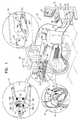
- Fig. 2Ais a schematic top-view of open-frame low-profile location pad 38, in accordance with an embodiment of the present invention.
- Pad 38comprises open-frame 37 on which generators 36A-36D are arranged in a planar rectangular configuration.
- the distance between any pair of field-generatorsis typically in the range of several centimeters to several tens of centimeters (e.g., 8-55 cm), although other distances can also be used.
- the figurealso illustrates ROI 39 of fluoroscopic system 22.
- Distal end 34 of catheter 24is located within ROI 39.
- Position sensor 41which is installed near the distal end of the catheter, is configured to sense the magnetic fields from field-generators 36A-36D so as to form six dimensional position and orientation coordinates of the distal end.
- Field-generators 36A-36D of pad 38are typically arranged around ROI 39 in any suitable arrangement, such as on a triangle or a rectangle.
- pad 38comprises four field-generators 36A-36D that are arranged in a rectangular shape and fixed on frame 37.
- An inset 58comprises an exploded view of field-generator 36C, which is substantially similar to field-generators 36A, 36B, and 36D, and is fixed on frame 37.
- field-generator 36Ccomprises a base-frame 59, three non-concentric orthogonal coils 62, 64 and 66, arranged adjacent to one another within the base-frame, and a cap 60, which encloses the coils within the base-frame.
- at least two of the coils, but not necessarily all the coils,are non-concentric.
- the coilsmay be arranged relative to one another in any non-parallel configuration that may not be necessarily orthogonal.
- the respective generated magnetic fieldsare not parallel, however not necessarily orthogonal to one another.
- coils 62, 64 and 66are wound and oriented in three mutually-orthogonal axes. Each coil is thus configured to generate a magnetic field component in one direction out of three mutually-orthogonal directions.
- Coils 64 and 66typically comprise flat coils typically in the range of 6-10 mm (e.g., 8 mm) thick and are located side-by-side in a single plane whereas coil 62 is located around them. This arrangement allows packaging the three non-concentric coils in a planar field-generator.
- each coil(e.g., coils 62, 64, 66) comprises a fiber core 65, typically made of carbon, and wires 63, typically made of copper. Wires 63 are wrapped around core 65.
- the coilsare typically in the range of 6-10 mm (e.g., 8 mm) thick and the overall dimension of pad 38 may be 50 cm or any other suitable size.
- Each coilgenerates a magnetic field typically in a direction orthogonal to the orientation of the coil wrappings, when applying electrical current to the wires of the coil.
- each field-generatormay comprise three concentric coils. Such configuration, however, typically results in a thicker field-generator.
- frame 37comprises three solid arms that are made of a suitable material such as plastic or fiberglass.
- the fourth side of the rectanglee.g., the side between field-generators 36A and 36D
- the fourth side of the rectangleis deliberately open so as to form the open-frame. As shown in Fig. 1 , the open side is located below patient's heart 28 and thus enables unobstructed fluoroscopic imaging throughout ROI 39.
- open and open siderefer to a side of frame 37 that is transparent to X-ray radiation, and therefore invisible to fluoroscopic system 22.
- the open sidemay be mechanically closed to some extent, as long as transparency to X-ray radiation is maintained.
- Such configurationsmay enable unobstructed fluoroscopic imaging, and at the same time provide sufficient mechanical rigidity to the location pad.
- field-generators 36A and 36Dmay be connected by an arm made of a material transparent to X-ray radiation, by a perforated arm that allows a sufficient portion of the X-ray radiation to pass through, or by any other means.
- Fig. 2Bis a schematic side-view of pad 38, in accordance with an embodiment of the present invention.
- Pad 38comprises low-profile frame 37 formed by frame material with a typical thickness of 1.2 cm.
- Generators 36B and 36Care fixed on frame 37 (together with generators 36A and 36D, which are invisible in this side-view).
- pad 38is located between table 33 and mattress 35 on which patient 30 lies.
- pad 38allows positioning the pad directly on table 33 and beneath the patient without causing inconvenience.
- mattress 35may be optional, and in alternative embodiments, pad 38 may be formed to provide the required flatness and convenience for patient 30, so as to allow direct contact between the patient's torso and respective generators 36A-36D.
- the close proximity of pad 38 to patient 30reduces shadowing effects that the pad may have on the X-rays. This effect is especially noticeable while irradiating patient 30 by system 22 at an angle that is not orthogonal to the plane of the location pad. Additionally, the close proximity between the location pad and the catheter may improve the measurement accuracy of the location of the distal end.
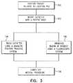
- FIG. 3is a flow chart that schematically illustrates a method for simultaneous imaging and position tracking during a catheterization procedure, in accordance with embodiments of the present invention.
- the methodbegins by positioning patient 30 on table 33, relative to location pad 38, wherein the pad is positioned between the table and the patient's torso, at a patient positioning step 100.
- the cardiologistinserts catheter 24 into the patient body, at a catheter insertion step 102.
- the cardiologisttracks the position of distal end 34 in the patient's heart using magnetic position system 20, at a tracking step 104.
- the cardiologistmay decide to irradiate ROI 39 of the patient using system 22, at an irradiation step 106.
- the disclosed techniquesallow unobstructed imaging of ROI 39 that provides the cardiologist with the required fluoroscopic images so as to carry out ablation of the respective tissue, at a procedure carry out step 108.
Landscapes
- Health & Medical Sciences (AREA)
- Life Sciences & Earth Sciences (AREA)
- Engineering & Computer Science (AREA)
- Surgery (AREA)
- Medical Informatics (AREA)
- Public Health (AREA)
- Biomedical Technology (AREA)
- Heart & Thoracic Surgery (AREA)
- Molecular Biology (AREA)
- Animal Behavior & Ethology (AREA)
- General Health & Medical Sciences (AREA)
- Veterinary Medicine (AREA)
- Pathology (AREA)
- Nuclear Medicine, Radiotherapy & Molecular Imaging (AREA)
- Physics & Mathematics (AREA)
- Biophysics (AREA)
- Power Engineering (AREA)
- Human Computer Interaction (AREA)
- Robotics (AREA)
- Optics & Photonics (AREA)
- Radiology & Medical Imaging (AREA)
- Oral & Maxillofacial Surgery (AREA)
- High Energy & Nuclear Physics (AREA)
- Apparatus For Radiation Diagnosis (AREA)
- Magnetic Resonance Imaging Apparatus (AREA)
- Media Introduction/Drainage Providing Device (AREA)
- Measurement Of Length, Angles, Or The Like Using Electric Or Magnetic Means (AREA)
Abstract
Description
- This application is a continuation-in-part of
U.S. Patent Application 14/791,667, filed July 6, 2015 - The present invention relates generally to position tracking systems, and specifically to location pads used in magnetic position tracking.
- Magnetic position tracking systems are used in a wide range of medical applications, such as in minimally invasive procedures. Examples of prior art techniques are provided below.
U.S. Patent application publication 2007/0265526, to Govari, et al. , whose disclosure is incorporated herein by reference, describes a magnetic position tracking system for performing a medical procedure on a patient who is positioned on an upper surface of a table includes a location pad, which is positioned on the upper surface of the table beneath the patient. The location pad includes one or more field-generators, which are operative to generate respective magnetic fields and are arranged so that a thickness dimension of the location pad is no greater than 3 centimeters. A position sensor is fixed to an invasive medical device for insertion into a body of the patient, and is arranged to sense the magnetic fields so as to measure a position of the medical device in the body.U.S. Patent 8,180,430, to Govari, et al. , whose disclosure is incorporated herein by reference, describes a method for position tracking, including using first and second field-generators located at respective different first and second locations to generate respective first and second magnetic fields in a vicinity of first and second objects.- Documents incorporated by reference in the present patent application are to be considered an integral part of the application except that, to the extent that any terms are defined in these incorporated documents in a manner that conflicts with definitions made explicitly or implicitly in the present specification, only the definitions in the present specification should be considered.
- An embodiment of the present invention that is described herein provides a field generator including multiple planar coils that are arranged in a single plane. At least two of the coils are non-concentric and are wound around respective axes that are not parallel with one another, so as to generate respective magnetic fields that are not parallel with one another.
- In some embodiments, at least two of the magnetic fields are oriented in mutually-orthogonal directions. In other embodiments, the non-concentric coils are arranged side-by-side in the single plane. In yet other embodiments, the at least two coils include respective cores oriented at the respective axes, and respective wires wound around the cores. In an embodiment, the cores include carbon. In another embodiment, each of the at least two coils has a thickness between 6mm and 10mm.
- There is additionally provided, in accordance with an embodiment of the present invention, a method for producing a field generator including providing multiple planar coils. The planar coils are arranged in a single plane, such that at least two of the coils are non-concentric and the coils are wound around respective axes that are not parallel with one another.
- There is additionally provided, in accordance with an embodiment of the present invention, a method for generating magnetic fields including providing a field generator, including multiple planar coils that are arranged in a single plane. At least two of the coils are non-concentric and are wound around respective axes that are not parallel with one another. Electrical currents are driven into the multiple planar coils so as to generate respective magnetic fields that are not parallel with one another.
- The present disclosure will be more fully understood from the following detailed description of the embodiments thereof, taken together with the drawings, in which:
FIG. 1 is a schematic pictorial illustration of a fluoroscopic imaging system and a magnetic position tracking system, in accordance with an embodiment of the present invention;FIG. 2A is a schematic top-view of an open-frame low-profile location pad, in accordance with an embodiment of the present invention;FIG. 2B is a schematic side-view of an open-frame low-profile location pad, in accordance with an embodiment of the present invention; andFIG. 3 is a flow chart that schematically illustrates a method for simultaneous imaging and position tracking, in accordance with embodiments of the present invention.- Intra-body probes, such as catheters, are used in various therapeutic and diagnostic medical procedures. The probe is inserted into the living body of a patient and navigated to the target region in a body cavity to perform the medical procedure. In some magnetic-field-based position tracking systems, an external magnetic field is applied to the patient's body. A position sensor installed near the distal end of the catheter responds to the field by producing an electrical signal. The tracking system uses the signal to locate the position and orientation of the catheter relative to the patient's body. The magnetic field is typically produced by multiple field-generators, e.g., field-generating coils, fixed on a surface so as to form a location pad.
- In some scenarios, it is desirable to operate a fluoroscopic system simultaneously with the magnetic position tracking system, in order to acquire an image of a region-of-interest (ROI) of the organ in question. In an intra-cardiac procedure, for example, the ROI of both systems comprises the left-hand-side of the patient's chest. In such scenarios, parts of the location pad of the magnetic position tracking system may fall within the Field-Of-View (FOV) of the fluoroscopic system, and may block or obscure portions of the fluoroscopic image.
- Embodiments of the present invention that are described herein provide open-frame and low-profile (e.g., thin) location pad configurations. The disclosed location pads comprise multiple magnetic field-generators (e.g., planar coils) that are fixed on a frame (e.g., a triangle or a rectangle frame) at respective positions surrounding the ROI. The frame is open on at least one side of the ROI, typically the side facing the fluoroscopic system. As a result, the location pad causes little or no obstruction to the fluoroscopic imaging, at least in fluoroscopic projections that are commonly used in cardiac procedures.
- The disclosed location pads have a low profile, e.g., a thickness on the order of 1.2 cm. Such a location pad can be easily placed between a moving table (on which the patient is positioned) and the patient's body, as opposed to conventional location pads that are thicker and have to be placed below the table.
- In an embodiment, each of the field-generators comprises three concentric planar coils that are configured in non-parallel directions (e.g., orthogonally) relative to one another so as to generate magnetic field components in three respective non-parallel (e.g., orthogonal) directions. In an alternative embodiment, at least two of the planar coils (e.g., all three coils) are arranged in a non-concentric configuration, e.g., side-by-side in a single plane, so as to reduce the thickness of the field-generator.
FIG. 1 is a schematic pictorial illustration of afluoroscopic imaging system 22 and a magneticposition tracking system 20 applied in a medical procedure, in accordance with an embodiment of the present invention.- A cardiologist 42 (or any other qualified user) navigates
catheter 24 in aheart 28 of a patient 30 (shown in an inset 32) using aposition sensor 41 installed near the distal end of the catheter, untildistal end 34 reaches the desired location.Cardiologist 42 then performs a desired medical procedure, such as ablation or mapping, usingcatheter 24.Position sensor 41 is configured to sense magnetic fields generated by field-generators 36A-36D and to transmit signals to aprocessor 44 for determining of the distal end, e.g., six dimensional position and orientation coordinates (X, Y, Z, pitch, yaw, roll). - Magnetic position tracking is implemented, for example, in the CARTO™ system, produced by Biosense Webster Inc. (Diamond Bar, Calif.) and is described in detail in
U.S. Patents 5,391,199 ,6,690,963 ,6,484,118 ,6,239,724 ,6,618,612 and6,332,089 , inPCT Patent Publication WO 96/05768 U.S. Patent Application Publications 2002/0065455 A1 ,2003/0120150 A1 and2004/0068178 A1 , whose disclosures are all incorporated herein by reference. - A
console 26 comprisesprocessor 44, adriver circuit 50, aninterface 48 tofluoroscopic imaging system 22,input devices 46, and adisplay 40.System 20 comprises a low-profile location pad 38 that may be rectangular, although other suitable shapes can also be used. The dimensions ofpad 38 are typically about 1.2 cm in thickness and 50 cm in length and width, although other shapes and corresponding dimensions may be used. The pad comprises aframe 37 and one or more magnetic field-generators, such as field-generating coils, fixed onframe 37. In the exemplary configuration shown in aninset 29 ofFIG. 1 ,pad 38 comprises four field-generators 36A-36D. - The location pad is placed on top of a catheterization table 33 and under the patient's torso, such that
generators 36A-36D are located at fixed, known positions external to the patient. In alternative embodiments,pad 38 may comprise three generators, or any other suitable number.Driver circuit 50 drives field-generators 36A-36D with suitable signals so as to generate magnetic fields in a predefined working volume aroundheart 28. - In an embodiment, a
mattress 35 is placed beneathpatient 30 andpad 38 is located beneath the mattress and above table 33. In another embodiment, the field-generators are attached to the patient's torso and the patient lying directly on table 33. In an alternative embodiment,pad 38 is located beneath table 33. In case a fluoroscopic image is needed,cardiologist 42 usesinput devices 46 and a suitable Graphical User Interface (GUI) ondisplay 40 to request a fluoroscopic image in patient'sheart 28.Processor 44 is configured to calculate and display a Region-of-Interest (ROI) 39 to be irradiated bysystem 22. - Referring to an
inset 27,generators 36A-36D are typically located aroundROI 39. In an embodiment,pad 38 comprises an open-frame 37 aroundROI 39 so as to allow irradiated X-rays fromsystem 22 to pass through the open side ofpad 38. As can be seen in the figure, the open side offrame 38 faces the fluoroscopic system. In this arrangement,location pad 38 causes little or no obstruction or shadowing to the fluoroscopic imaging, at least in most commonly-used fluoroscopic projections (e.g., AP, LAO and RAO). - A traditional close-frame pad may block some of the X-rays and thus, blocking required cardiac imaging from
cardiologist 42 and reducing the effective size ofROI 39. The disclosed technique overcomes this limitation by eliminating one side or any other suitable part offrame 37 so as to provide the user with imaging of the full area ofROI 39. Additional embodiments of the pad are described in greater details inFigs. 2A and 2B . - Although
FIG. 1 shows a system for cardiac catheterization, open-frame location pads such aspad 38 can be used in any other position tracking application, such as for tracking orthopedic implants and various medical tools. In the example ofFIG. 1 the location pad is placed horizontally and has a reduced height or vertical dimension. The methods and devices described herein can be used to reduce any desired dimension of the location pad, as appropriate for the particular application. Additionally, the methods and systems described herein can also be used in other applications that involve simultaneous mapping and Fluoroscopic imaging. Fig. 2A is a schematic top-view of open-frame low-profile location pad 38, in accordance with an embodiment of the present invention.Pad 38 comprises open-frame 37 on whichgenerators 36A-36D are arranged in a planar rectangular configuration. The distance between any pair of field-generators is typically in the range of several centimeters to several tens of centimeters (e.g., 8-55 cm), although other distances can also be used.- The figure also illustrates
ROI 39 offluoroscopic system 22.Distal end 34 ofcatheter 24 is located withinROI 39.Position sensor 41, which is installed near the distal end of the catheter, is configured to sense the magnetic fields from field-generators 36A-36D so as to form six dimensional position and orientation coordinates of the distal end. Field-generators 36A-36D ofpad 38 are typically arranged aroundROI 39 in any suitable arrangement, such as on a triangle or a rectangle. In the example ofFig. 2A ,pad 38 comprises four field-generators 36A-36D that are arranged in a rectangular shape and fixed onframe 37. - An
inset 58 comprises an exploded view of field-generator 36C, which is substantially similar to field-generators frame 37. In some embodiments, field-generator 36C comprises a base-frame 59, three non-concentricorthogonal coils cap 60, which encloses the coils within the base-frame. In other embodiments, at least two of the coils, but not necessarily all the coils, are non-concentric. - In yet other embodiments, the coils may be arranged relative to one another in any non-parallel configuration that may not be necessarily orthogonal. Thus, the respective generated magnetic fields are not parallel, however not necessarily orthogonal to one another.
- As can be seen in the figure, coils 62, 64 and 66 are wound and oriented in three mutually-orthogonal axes. Each coil is thus configured to generate a magnetic field component in one direction out of three mutually-orthogonal directions.
Coils coil 62 is located around them. This arrangement allows packaging the three non-concentric coils in a planar field-generator. - In an embodiment, each coil (e.g., coils 62, 64, 66) comprises a
fiber core 65, typically made of carbon, andwires 63, typically made of copper.Wires 63 are wrapped aroundcore 65. The coils are typically in the range of 6-10 mm (e.g., 8 mm) thick and the overall dimension ofpad 38 may be 50 cm or any other suitable size. Each coil generates a magnetic field typically in a direction orthogonal to the orientation of the coil wrappings, when applying electrical current to the wires of the coil. - In alternative embodiments, each field-generator may comprise three concentric coils. Such configuration, however, typically results in a thicker field-generator.
- In some embodiments,
frame 37 comprises three solid arms that are made of a suitable material such as plastic or fiberglass. The fourth side of the rectangle (e.g., the side between field-generators Fig. 1 , the open side is located below patient'sheart 28 and thus enables unobstructed fluoroscopic imaging throughoutROI 39. - In the context of the present patent application and in the claims, the terms "open" and "open side" refer to a side of
frame 37 that is transparent to X-ray radiation, and therefore invisible tofluoroscopic system 22. In alternative embodiments, the open side may be mechanically closed to some extent, as long as transparency to X-ray radiation is maintained. Such configurations may enable unobstructed fluoroscopic imaging, and at the same time provide sufficient mechanical rigidity to the location pad. For example, field-generators Fig. 2B is a schematic side-view ofpad 38, in accordance with an embodiment of the present invention.Pad 38 comprises low-profile frame 37 formed by frame material with a typical thickness of 1.2 cm.Generators generators pad 38 is located between table 33 andmattress 35 on whichpatient 30 lies.- The low profile of
pad 38 allows positioning the pad directly on table 33 and beneath the patient without causing inconvenience. Usingmattress 35 may be optional, and in alternative embodiments,pad 38 may be formed to provide the required flatness and convenience forpatient 30, so as to allow direct contact between the patient's torso andrespective generators 36A-36D. - The close proximity of
pad 38 to patient 30 (and therefore to the position sensor on the distal end of catheter 24), reduces shadowing effects that the pad may have on the X-rays. This effect is especially noticeable while irradiatingpatient 30 bysystem 22 at an angle that is not orthogonal to the plane of the location pad. Additionally, the close proximity between the location pad and the catheter may improve the measurement accuracy of the location of the distal end. FIG. 3 is a flow chart that schematically illustrates a method for simultaneous imaging and position tracking during a catheterization procedure, in accordance with embodiments of the present invention. The method begins by positioningpatient 30 on table 33, relative tolocation pad 38, wherein the pad is positioned between the table and the patient's torso, at apatient positioning step 100. The cardiologist insertscatheter 24 into the patient body, at acatheter insertion step 102. During the catheterization procedure, the cardiologist tracks the position ofdistal end 34 in the patient's heart usingmagnetic position system 20, at atracking step 104. In parallel, the cardiologist may decide to irradiateROI 39 of thepatient using system 22, at anirradiation step 106. The disclosed techniques allow unobstructed imaging ofROI 39 that provides the cardiologist with the required fluoroscopic images so as to carry out ablation of the respective tissue, at a procedure carry outstep 108.- It will be appreciated that the embodiments described above are cited by way of example, and that the present invention is not limited to what has been particularly shown and described hereinabove. Rather, the scope of the present invention includes both combinations and sub-combinations of the various features described hereinabove, as well as variations and modifications thereof which would occur to persons skilled in the art upon reading the foregoing description and which are not disclosed in the prior art.
Claims (12)
- A field generator, comprising multiple planar coils that are arranged in a single plane, wherein at least two of the coils are non-concentric and are wound around respective axes that are not parallel with one another, so as to generate respective magnetic fields that are not parallel with one another.
- The field generator according to claim 1, wherein at least two of the magnetic fields are oriented in mutually-orthogonal directions.
- The field generator according to claim 1, wherein the non-concentric coils are arranged side-by-side in the single plane.
- The field generator according to claim 1, wherein the at least two coils comprise respective cores oriented at the respective axes, and respective wires wound around the cores.
- The field generator according to claim 4, wherein the cores comprise carbon.
- The field generator according to claim 1, wherein each of the at least two coils has a thickness between 6mm and 10mm.
- A method for producing a field generator, the method comprising:providing multiple planar coils; andarranging the planar coils in a single plane, such that at least two of the coils are non-concentric and the coils are wound around respective axes that are not parallel with one another.
- The method according to claim 7, wherein arranging the planar coils comprises arranging the non-concentric coils side-by-side in the single plane.
- The method according to claim 7, wherein the at least two coils comprise respective cores oriented at the respective axes, and respective wires wound around the cores.
- The method according to claim 9, wherein the cores comprise carbon.
- The method according to claim 7, wherein each of the at least two coils has a thickness between 6mm and 10mm.
- A method for generating magnetic fields, the method comprising:providing a field generator, comprising multiple planar coils that are arranged in a single plane, wherein at least two of the coils are non-concentric and are wound around respective axes that are not parallel with one another; anddriving electrical currents into the multiple planar coils so as to generate respective magnetic fields that are not parallel with one another.
Applications Claiming Priority (2)
| Application Number | Priority Date | Filing Date | Title |
|---|---|---|---|
| US14/791,667US20170007155A1 (en) | 2015-07-06 | 2015-07-06 | Fluoro-invisible location pad structure for cardiac procedures |
| US15/059,628US11109774B2 (en) | 2015-07-06 | 2016-03-03 | Flat location pad using nonconcentric coils |
Publications (2)
| Publication Number | Publication Date |
|---|---|
| EP3114996A1true EP3114996A1 (en) | 2017-01-11 |
| EP3114996B1 EP3114996B1 (en) | 2019-10-09 |
Family
ID=56413478
Family Applications (2)
| Application Number | Title | Priority Date | Filing Date |
|---|---|---|---|
| EP16178004.4AActiveEP3114995B1 (en) | 2015-07-06 | 2016-07-05 | Fluoro-invisible location pad structure for cardiac procedures |
| EP16178006.9AActiveEP3114996B1 (en) | 2015-07-06 | 2016-07-05 | Magnetic field generators using nonconcentric coils |
Family Applications Before (1)
| Application Number | Title | Priority Date | Filing Date |
|---|---|---|---|
| EP16178004.4AActiveEP3114995B1 (en) | 2015-07-06 | 2016-07-05 | Fluoro-invisible location pad structure for cardiac procedures |
Country Status (8)
| Country | Link |
|---|---|
| US (1) | US11109774B2 (en) |
| EP (2) | EP3114995B1 (en) |
| JP (3) | JP6824649B2 (en) |
| CN (1) | CN106333750B (en) |
| AU (2) | AU2016204106A1 (en) |
| CA (2) | CA2934219A1 (en) |
| ES (2) | ES2761838T3 (en) |
| IL (2) | IL246418B (en) |
Families Citing this family (10)
| Publication number | Priority date | Publication date | Assignee | Title |
|---|---|---|---|---|
| US11109774B2 (en) | 2015-07-06 | 2021-09-07 | Biosense Webster (Israel) Ltd. | Flat location pad using nonconcentric coils |
| US11612437B2 (en)* | 2017-05-10 | 2023-03-28 | Biosense Webster (Israel) Ltd. | Location pad with improved immunity to interference |
| US10517612B2 (en) | 2017-09-19 | 2019-12-31 | Biosense Webster (Israel) Ltd. | Nail hole guiding system |
| EP3713493B1 (en) | 2018-02-14 | 2021-03-24 | St. Jude Medical International Holding S.à r.l. | Localized magnetic field transmitter |
| US11589770B2 (en) | 2019-12-30 | 2023-02-28 | Biosense Webster (Israel) Ltd. | Location pad for neurosurgical procedures |
| US12336767B2 (en)* | 2020-03-09 | 2025-06-24 | Biosense Webster (Israel) Ltd. | Finding roll angle of distal end of deflectable or non-deflectable invasive medical instrument |
| US11832883B2 (en) | 2020-04-23 | 2023-12-05 | Johnson & Johnson Surgical Vision, Inc. | Using real-time images for augmented-reality visualization of an ophthalmology surgical tool |
| US12201265B2 (en)* | 2020-04-23 | 2025-01-21 | Johnson & Johnson Surgical Vision, Inc. | Location pad surrounding at least part of patient eye for tracking position of a medical instrument |
| KR102379538B1 (en)* | 2020-07-07 | 2022-03-28 | 재단법인 한국마이크로의료로봇연구원 | Bed-integrated electromagnetic field device for micro robot movement control and microrobot driving method using the same |
| CN114557780B (en)* | 2022-03-01 | 2024-01-26 | 长春理工大学 | Three-dimensional positioning system and method for assisting surgery |
Citations (13)
| Publication number | Priority date | Publication date | Assignee | Title |
|---|---|---|---|---|
| US5391199A (en) | 1993-07-20 | 1995-02-21 | Biosense, Inc. | Apparatus and method for treating cardiac arrhythmias |
| WO1996005768A1 (en) | 1994-08-19 | 1996-02-29 | Biosense, Inc. | Medical diagnosis, treatment and imaging systems |
| US6239724B1 (en) | 1997-12-30 | 2001-05-29 | Remon Medical Technologies, Ltd. | System and method for telemetrically providing intrabody spatial position |
| US6332089B1 (en) | 1996-02-15 | 2001-12-18 | Biosense, Inc. | Medical procedures and apparatus using intrabody probes |
| US20020065455A1 (en) | 1995-01-24 | 2002-05-30 | Shlomo Ben-Haim | Medical diagnosis, treatment and imaging systems |
| US6484118B1 (en) | 2000-07-20 | 2002-11-19 | Biosense, Inc. | Electromagnetic position single axis system |
| EP1266610A2 (en)* | 2001-06-15 | 2002-12-18 | Biosense, Inc. | Method and system for measuring temperature and of adjusting for temperature sensitivity with a medical device having a position sensor |
| US20030120150A1 (en) | 2001-12-21 | 2003-06-26 | Assaf Govari | Wireless position sensor |
| US6618612B1 (en) | 1996-02-15 | 2003-09-09 | Biosense, Inc. | Independently positionable transducers for location system |
| US20040068178A1 (en) | 2002-09-17 | 2004-04-08 | Assaf Govari | High-gradient recursive locating system |
| EP1854405A1 (en)* | 2006-05-11 | 2007-11-14 | Biosense Webster, Inc. | Low-profile location pad |
| US20080174303A1 (en)* | 2007-01-18 | 2008-07-24 | General Electric Company | Anti-distortion electromagnetic sensor method and system |
| US8180430B2 (en) | 2005-02-22 | 2012-05-15 | Biosense Webster, Inc. | Resolution of magnetic dipole ambiguity in position tracking measurements |
Family Cites Families (14)
| Publication number | Priority date | Publication date | Assignee | Title |
|---|---|---|---|---|
| US5307072A (en)* | 1992-07-09 | 1994-04-26 | Polhemus Incorporated | Non-concentricity compensation in position and orientation measurement systems |
| AU706052B2 (en) | 1996-02-15 | 1999-06-10 | Biosense, Inc. | Movable transmit or receive coils for location system |
| US7366562B2 (en)* | 2003-10-17 | 2008-04-29 | Medtronic Navigation, Inc. | Method and apparatus for surgical navigation |
| AU1240801A (en)* | 1999-10-28 | 2001-05-08 | Enterprise Medical Technology, Inc. | Coil structures and methods for generating magnetic fields |
| US20040199072A1 (en) | 2003-04-01 | 2004-10-07 | Stacy Sprouse | Integrated electromagnetic navigation and patient positioning device |
| US7720521B2 (en) | 2004-04-21 | 2010-05-18 | Acclarent, Inc. | Methods and devices for performing procedures within the ear, nose, throat and paranasal sinuses |
| JP4709594B2 (en)* | 2004-08-03 | 2011-06-22 | オリンパス株式会社 | Magnetic guidance medical system |
| US7835785B2 (en)* | 2005-10-04 | 2010-11-16 | Ascension Technology Corporation | DC magnetic-based position and orientation monitoring system for tracking medical instruments |
| US8798711B2 (en)* | 2006-02-09 | 2014-08-05 | Biosense Webster, Inc. | Shielding of catheter handle |
| US8082020B2 (en)* | 2006-08-07 | 2011-12-20 | Biosense Webster, Inc. | Distortion-immune position tracking using redundant magnetic field measurements |
| US7782046B2 (en)* | 2007-02-05 | 2010-08-24 | General Electric Company | Electromagnetic tracking method and system |
| US8062229B2 (en)* | 2007-08-10 | 2011-11-22 | Rauscher Elizabeth A | Methods and devices for measurement and treatment of pain and the treatment of inflammation and osteoporosis |
| US9326702B2 (en) | 2013-03-15 | 2016-05-03 | Mediguide Ltd. | Medical device navigation system |
| US11109774B2 (en) | 2015-07-06 | 2021-09-07 | Biosense Webster (Israel) Ltd. | Flat location pad using nonconcentric coils |
- 2016
- 2016-03-03USUS15/059,628patent/US11109774B2/ennot_activeExpired - Fee Related
- 2016-06-17AUAU2016204106Apatent/AU2016204106A1/ennot_activeAbandoned
- 2016-06-22AUAU2016204257Apatent/AU2016204257A1/ennot_activeAbandoned
- 2016-06-23ILIL246418Apatent/IL246418B/enactiveIP Right Grant
- 2016-06-23ILIL246419Apatent/IL246419B/enactiveIP Right Grant
- 2016-06-27CACA2934219Apatent/CA2934219A1/ennot_activeAbandoned
- 2016-07-05EPEP16178004.4Apatent/EP3114995B1/enactiveActive
- 2016-07-05EPEP16178006.9Apatent/EP3114996B1/enactiveActive
- 2016-07-05ESES16178004Tpatent/ES2761838T3/enactiveActive
- 2016-07-05JPJP2016133070Apatent/JP6824649B2/ennot_activeExpired - Fee Related
- 2016-07-05CACA2935278Apatent/CA2935278A1/ennot_activeAbandoned
- 2016-07-05ESES16178006Tpatent/ES2764397T3/enactiveActive
- 2016-07-05JPJP2016133060Apatent/JP6776027B2/ennot_activeExpired - Fee Related
- 2016-07-06CNCN201610529399.1Apatent/CN106333750B/ennot_activeExpired - Fee Related
- 2020
- 2020-08-17JPJP2020137379Apatent/JP2021006812A/enactivePending
Patent Citations (15)
| Publication number | Priority date | Publication date | Assignee | Title |
|---|---|---|---|---|
| US5391199A (en) | 1993-07-20 | 1995-02-21 | Biosense, Inc. | Apparatus and method for treating cardiac arrhythmias |
| WO1996005768A1 (en) | 1994-08-19 | 1996-02-29 | Biosense, Inc. | Medical diagnosis, treatment and imaging systems |
| US20020065455A1 (en) | 1995-01-24 | 2002-05-30 | Shlomo Ben-Haim | Medical diagnosis, treatment and imaging systems |
| US6690963B2 (en) | 1995-01-24 | 2004-02-10 | Biosense, Inc. | System for determining the location and orientation of an invasive medical instrument |
| US6332089B1 (en) | 1996-02-15 | 2001-12-18 | Biosense, Inc. | Medical procedures and apparatus using intrabody probes |
| US6618612B1 (en) | 1996-02-15 | 2003-09-09 | Biosense, Inc. | Independently positionable transducers for location system |
| US6239724B1 (en) | 1997-12-30 | 2001-05-29 | Remon Medical Technologies, Ltd. | System and method for telemetrically providing intrabody spatial position |
| US6484118B1 (en) | 2000-07-20 | 2002-11-19 | Biosense, Inc. | Electromagnetic position single axis system |
| EP1266610A2 (en)* | 2001-06-15 | 2002-12-18 | Biosense, Inc. | Method and system for measuring temperature and of adjusting for temperature sensitivity with a medical device having a position sensor |
| US20030120150A1 (en) | 2001-12-21 | 2003-06-26 | Assaf Govari | Wireless position sensor |
| US20040068178A1 (en) | 2002-09-17 | 2004-04-08 | Assaf Govari | High-gradient recursive locating system |
| US8180430B2 (en) | 2005-02-22 | 2012-05-15 | Biosense Webster, Inc. | Resolution of magnetic dipole ambiguity in position tracking measurements |
| EP1854405A1 (en)* | 2006-05-11 | 2007-11-14 | Biosense Webster, Inc. | Low-profile location pad |
| US20070265526A1 (en) | 2006-05-11 | 2007-11-15 | Assaf Govari | Low-profile location pad |
| US20080174303A1 (en)* | 2007-01-18 | 2008-07-24 | General Electric Company | Anti-distortion electromagnetic sensor method and system |
Also Published As
| Publication number | Publication date |
|---|---|
| JP2021006812A (en) | 2021-01-21 |
| ES2764397T3 (en) | 2020-06-03 |
| ES2761838T3 (en) | 2020-05-21 |
| EP3114996B1 (en) | 2019-10-09 |
| CN106333750B (en) | 2021-04-02 |
| JP2017015708A (en) | 2017-01-19 |
| US11109774B2 (en) | 2021-09-07 |
| JP6776027B2 (en) | 2020-10-28 |
| IL246419B (en) | 2020-04-30 |
| AU2016204106A1 (en) | 2017-02-02 |
| IL246419A0 (en) | 2016-11-30 |
| JP2017012760A (en) | 2017-01-19 |
| IL246418A0 (en) | 2016-11-30 |
| CA2935278A1 (en) | 2017-01-06 |
| CN106333750A (en) | 2017-01-18 |
| CA2934219A1 (en) | 2017-01-06 |
| IL246418B (en) | 2020-08-31 |
| AU2016204257A1 (en) | 2017-02-02 |
| JP6824649B2 (en) | 2021-02-03 |
| EP3114995B1 (en) | 2019-10-16 |
| US20170007156A1 (en) | 2017-01-12 |
| EP3114995A1 (en) | 2017-01-11 |
Similar Documents
| Publication | Publication Date | Title |
|---|---|---|
| EP3114996B1 (en) | Magnetic field generators using nonconcentric coils | |
| US20200383603A1 (en) | Localized magnetic field generator | |
| US20170007155A1 (en) | Fluoro-invisible location pad structure for cardiac procedures | |
| EP3703605B1 (en) | Mechanical design considerations for table-mounted device used as a sub-assembly in a magnetic tracking system working in conjunction with an x-ray imaging system | |
| US20230124397A1 (en) | Location pad for neurosurgical procedures | |
| US11839461B2 (en) | Localized magnetic field transmitter | |
| Poma | Evaluation of Tracking Methods for Percutaneous Procedures With Numerical Simulation and Experimental Validation |
Legal Events
| Date | Code | Title | Description |
|---|---|---|---|
| PUAI | Public reference made under article 153(3) epc to a published international application that has entered the european phase | Free format text:ORIGINAL CODE: 0009012 | |
| STAA | Information on the status of an ep patent application or granted ep patent | Free format text:STATUS: THE APPLICATION HAS BEEN PUBLISHED | |
| AK | Designated contracting states | Kind code of ref document:A1 Designated state(s):AL AT BE BG CH CY CZ DE DK EE ES FI FR GB GR HR HU IE IS IT LI LT LU LV MC MK MT NL NO PL PT RO RS SE SI SK SM TR | |
| AX | Request for extension of the european patent | Extension state:BA ME | |
| STAA | Information on the status of an ep patent application or granted ep patent | Free format text:STATUS: REQUEST FOR EXAMINATION WAS MADE | |
| 17P | Request for examination filed | Effective date:20170317 | |
| RBV | Designated contracting states (corrected) | Designated state(s):AL AT BE BG CH CY CZ DE DK EE ES FI FR GB GR HR HU IE IS IT LI LT LU LV MC MK MT NL NO PL PT RO RS SE SI SK SM TR | |
| GRAP | Despatch of communication of intention to grant a patent | Free format text:ORIGINAL CODE: EPIDOSNIGR1 | |
| STAA | Information on the status of an ep patent application or granted ep patent | Free format text:STATUS: GRANT OF PATENT IS INTENDED | |
| RIC1 | Information provided on ipc code assigned before grant | Ipc:A61B 34/20 20160101ALI20181029BHEP Ipc:A61B 6/00 20060101ALI20181029BHEP Ipc:A61B 90/00 20160101ALI20181029BHEP Ipc:H01F 27/28 20060101ALI20181029BHEP Ipc:A61B 5/06 20060101AFI20181029BHEP | |
| INTG | Intention to grant announced | Effective date:20181123 | |
| GRAS | Grant fee paid | Free format text:ORIGINAL CODE: EPIDOSNIGR3 | |
| GRAJ | Information related to disapproval of communication of intention to grant by the applicant or resumption of examination proceedings by the epo deleted | Free format text:ORIGINAL CODE: EPIDOSDIGR1 | |
| GRAL | Information related to payment of fee for publishing/printing deleted | Free format text:ORIGINAL CODE: EPIDOSDIGR3 | |
| STAA | Information on the status of an ep patent application or granted ep patent | Free format text:STATUS: REQUEST FOR EXAMINATION WAS MADE | |
| GRAP | Despatch of communication of intention to grant a patent | Free format text:ORIGINAL CODE: EPIDOSNIGR1 | |
| STAA | Information on the status of an ep patent application or granted ep patent | Free format text:STATUS: GRANT OF PATENT IS INTENDED | |
| INTC | Intention to grant announced (deleted) | ||
| INTG | Intention to grant announced | Effective date:20190430 | |
| GRAA | (expected) grant | Free format text:ORIGINAL CODE: 0009210 | |
| STAA | Information on the status of an ep patent application or granted ep patent | Free format text:STATUS: THE PATENT HAS BEEN GRANTED | |
| AK | Designated contracting states | Kind code of ref document:B1 Designated state(s):AL AT BE BG CH CY CZ DE DK EE ES FI FR GB GR HR HU IE IS IT LI LT LU LV MC MK MT NL NO PL PT RO RS SE SI SK SM TR | |
| REG | Reference to a national code | Ref country code:GB Ref legal event code:FG4D | |
| REG | Reference to a national code | Ref country code:CH Ref legal event code:EP Ref country code:CH Ref legal event code:NV Representative=s name:E. BLUM AND CO. AG PATENT- UND MARKENANWAELTE , CH | |
| REG | Reference to a national code | Ref country code:IE Ref legal event code:FG4D | |
| REG | Reference to a national code | Ref country code:DE Ref legal event code:R096 Ref document number:602016021977 Country of ref document:DE | |
| REG | Reference to a national code | Ref country code:AT Ref legal event code:REF Ref document number:1187847 Country of ref document:AT Kind code of ref document:T Effective date:20191115 | |
| REG | Reference to a national code | Ref country code:NL Ref legal event code:FP | |
| REG | Reference to a national code | Ref country code:LT Ref legal event code:MG4D | |
| REG | Reference to a national code | Ref country code:AT Ref legal event code:MK05 Ref document number:1187847 Country of ref document:AT Kind code of ref document:T Effective date:20191009 | |
| PG25 | Lapsed in a contracting state [announced via postgrant information from national office to epo] | Ref country code:PL Free format text:LAPSE BECAUSE OF FAILURE TO SUBMIT A TRANSLATION OF THE DESCRIPTION OR TO PAY THE FEE WITHIN THE PRESCRIBED TIME-LIMIT Effective date:20191009 Ref country code:BG Free format text:LAPSE BECAUSE OF FAILURE TO SUBMIT A TRANSLATION OF THE DESCRIPTION OR TO PAY THE FEE WITHIN THE PRESCRIBED TIME-LIMIT Effective date:20200109 Ref country code:LT Free format text:LAPSE BECAUSE OF FAILURE TO SUBMIT A TRANSLATION OF THE DESCRIPTION OR TO PAY THE FEE WITHIN THE PRESCRIBED TIME-LIMIT Effective date:20191009 Ref country code:FI Free format text:LAPSE BECAUSE OF FAILURE TO SUBMIT A TRANSLATION OF THE DESCRIPTION OR TO PAY THE FEE WITHIN THE PRESCRIBED TIME-LIMIT Effective date:20191009 Ref country code:LV Free format text:LAPSE BECAUSE OF FAILURE TO SUBMIT A TRANSLATION OF THE DESCRIPTION OR TO PAY THE FEE WITHIN THE PRESCRIBED TIME-LIMIT Effective date:20191009 Ref country code:SE Free format text:LAPSE BECAUSE OF FAILURE TO SUBMIT A TRANSLATION OF THE DESCRIPTION OR TO PAY THE FEE WITHIN THE PRESCRIBED TIME-LIMIT Effective date:20191009 Ref country code:NO Free format text:LAPSE BECAUSE OF FAILURE TO SUBMIT A TRANSLATION OF THE DESCRIPTION OR TO PAY THE FEE WITHIN THE PRESCRIBED TIME-LIMIT Effective date:20200109 Ref country code:GR Free format text:LAPSE BECAUSE OF FAILURE TO SUBMIT A TRANSLATION OF THE DESCRIPTION OR TO PAY THE FEE WITHIN THE PRESCRIBED TIME-LIMIT Effective date:20200110 Ref country code:PT Free format text:LAPSE BECAUSE OF FAILURE TO SUBMIT A TRANSLATION OF THE DESCRIPTION OR TO PAY THE FEE WITHIN THE PRESCRIBED TIME-LIMIT Effective date:20200210 Ref country code:AT Free format text:LAPSE BECAUSE OF FAILURE TO SUBMIT A TRANSLATION OF THE DESCRIPTION OR TO PAY THE FEE WITHIN THE PRESCRIBED TIME-LIMIT Effective date:20191009 | |
| PG25 | Lapsed in a contracting state [announced via postgrant information from national office to epo] | Ref country code:IS Free format text:LAPSE BECAUSE OF FAILURE TO SUBMIT A TRANSLATION OF THE DESCRIPTION OR TO PAY THE FEE WITHIN THE PRESCRIBED TIME-LIMIT Effective date:20200224 Ref country code:HR Free format text:LAPSE BECAUSE OF FAILURE TO SUBMIT A TRANSLATION OF THE DESCRIPTION OR TO PAY THE FEE WITHIN THE PRESCRIBED TIME-LIMIT Effective date:20191009 Ref country code:RS Free format text:LAPSE BECAUSE OF FAILURE TO SUBMIT A TRANSLATION OF THE DESCRIPTION OR TO PAY THE FEE WITHIN THE PRESCRIBED TIME-LIMIT Effective date:20191009 | |
| REG | Reference to a national code | Ref country code:ES Ref legal event code:FG2A Ref document number:2764397 Country of ref document:ES Kind code of ref document:T3 Effective date:20200603 | |
| PG25 | Lapsed in a contracting state [announced via postgrant information from national office to epo] | Ref country code:AL Free format text:LAPSE BECAUSE OF FAILURE TO SUBMIT A TRANSLATION OF THE DESCRIPTION OR TO PAY THE FEE WITHIN THE PRESCRIBED TIME-LIMIT Effective date:20191009 | |
| REG | Reference to a national code | Ref country code:DE Ref legal event code:R097 Ref document number:602016021977 Country of ref document:DE | |
| PG2D | Information on lapse in contracting state deleted | Ref country code:IS | |
| PG25 | Lapsed in a contracting state [announced via postgrant information from national office to epo] | Ref country code:DK Free format text:LAPSE BECAUSE OF FAILURE TO SUBMIT A TRANSLATION OF THE DESCRIPTION OR TO PAY THE FEE WITHIN THE PRESCRIBED TIME-LIMIT Effective date:20191009 Ref country code:EE Free format text:LAPSE BECAUSE OF FAILURE TO SUBMIT A TRANSLATION OF THE DESCRIPTION OR TO PAY THE FEE WITHIN THE PRESCRIBED TIME-LIMIT Effective date:20191009 Ref country code:RO Free format text:LAPSE BECAUSE OF FAILURE TO SUBMIT A TRANSLATION OF THE DESCRIPTION OR TO PAY THE FEE WITHIN THE PRESCRIBED TIME-LIMIT Effective date:20191009 Ref country code:CZ Free format text:LAPSE BECAUSE OF FAILURE TO SUBMIT A TRANSLATION OF THE DESCRIPTION OR TO PAY THE FEE WITHIN THE PRESCRIBED TIME-LIMIT Effective date:20191009 Ref country code:IS Free format text:LAPSE BECAUSE OF FAILURE TO SUBMIT A TRANSLATION OF THE DESCRIPTION OR TO PAY THE FEE WITHIN THE PRESCRIBED TIME-LIMIT Effective date:20200209 | |
| PLBE | No opposition filed within time limit | Free format text:ORIGINAL CODE: 0009261 | |
| STAA | Information on the status of an ep patent application or granted ep patent | Free format text:STATUS: NO OPPOSITION FILED WITHIN TIME LIMIT | |
| PG25 | Lapsed in a contracting state [announced via postgrant information from national office to epo] | Ref country code:SM Free format text:LAPSE BECAUSE OF FAILURE TO SUBMIT A TRANSLATION OF THE DESCRIPTION OR TO PAY THE FEE WITHIN THE PRESCRIBED TIME-LIMIT Effective date:20191009 Ref country code:SK Free format text:LAPSE BECAUSE OF FAILURE TO SUBMIT A TRANSLATION OF THE DESCRIPTION OR TO PAY THE FEE WITHIN THE PRESCRIBED TIME-LIMIT Effective date:20191009 | |
| 26N | No opposition filed | Effective date:20200710 | |
| PG25 | Lapsed in a contracting state [announced via postgrant information from national office to epo] | Ref country code:SI Free format text:LAPSE BECAUSE OF FAILURE TO SUBMIT A TRANSLATION OF THE DESCRIPTION OR TO PAY THE FEE WITHIN THE PRESCRIBED TIME-LIMIT Effective date:20191009 | |
| PG25 | Lapsed in a contracting state [announced via postgrant information from national office to epo] | Ref country code:MC Free format text:LAPSE BECAUSE OF FAILURE TO SUBMIT A TRANSLATION OF THE DESCRIPTION OR TO PAY THE FEE WITHIN THE PRESCRIBED TIME-LIMIT Effective date:20191009 | |
| REG | Reference to a national code | Ref country code:CH Ref legal event code:PL | |
| REG | Reference to a national code | Ref country code:BE Ref legal event code:MM Effective date:20200731 | |
| PG25 | Lapsed in a contracting state [announced via postgrant information from national office to epo] | Ref country code:CH Free format text:LAPSE BECAUSE OF NON-PAYMENT OF DUE FEES Effective date:20200731 Ref country code:LI Free format text:LAPSE BECAUSE OF NON-PAYMENT OF DUE FEES Effective date:20200731 Ref country code:LU Free format text:LAPSE BECAUSE OF NON-PAYMENT OF DUE FEES Effective date:20200705 Ref country code:IE Free format text:LAPSE BECAUSE OF NON-PAYMENT OF DUE FEES Effective date:20200705 | |
| PG25 | Lapsed in a contracting state [announced via postgrant information from national office to epo] | Ref country code:BE Free format text:LAPSE BECAUSE OF NON-PAYMENT OF DUE FEES Effective date:20200731 | |
| PGFP | Annual fee paid to national office [announced via postgrant information from national office to epo] | Ref country code:FR Payment date:20210611 Year of fee payment:6 Ref country code:IT Payment date:20210610 Year of fee payment:6 | |
| PGFP | Annual fee paid to national office [announced via postgrant information from national office to epo] | Ref country code:GB Payment date:20210609 Year of fee payment:6 Ref country code:NL Payment date:20210716 Year of fee payment:6 | |
| REG | Reference to a national code | Ref country code:ES Ref legal event code:FD2A Effective date:20211126 | |
| PGFP | Annual fee paid to national office [announced via postgrant information from national office to epo] | Ref country code:DE Payment date:20210608 Year of fee payment:6 | |
| PG25 | Lapsed in a contracting state [announced via postgrant information from national office to epo] | Ref country code:ES Free format text:LAPSE BECAUSE OF NON-PAYMENT OF DUE FEES Effective date:20200706 | |
| PG25 | Lapsed in a contracting state [announced via postgrant information from national office to epo] | Ref country code:TR Free format text:LAPSE BECAUSE OF FAILURE TO SUBMIT A TRANSLATION OF THE DESCRIPTION OR TO PAY THE FEE WITHIN THE PRESCRIBED TIME-LIMIT Effective date:20191009 Ref country code:MT Free format text:LAPSE BECAUSE OF FAILURE TO SUBMIT A TRANSLATION OF THE DESCRIPTION OR TO PAY THE FEE WITHIN THE PRESCRIBED TIME-LIMIT Effective date:20191009 Ref country code:CY Free format text:LAPSE BECAUSE OF FAILURE TO SUBMIT A TRANSLATION OF THE DESCRIPTION OR TO PAY THE FEE WITHIN THE PRESCRIBED TIME-LIMIT Effective date:20191009 | |
| PG25 | Lapsed in a contracting state [announced via postgrant information from national office to epo] | Ref country code:MK Free format text:LAPSE BECAUSE OF FAILURE TO SUBMIT A TRANSLATION OF THE DESCRIPTION OR TO PAY THE FEE WITHIN THE PRESCRIBED TIME-LIMIT Effective date:20191009 | |
| REG | Reference to a national code | Ref country code:DE Ref legal event code:R119 Ref document number:602016021977 Country of ref document:DE | |
| REG | Reference to a national code | Ref country code:NL Ref legal event code:MM Effective date:20220801 | |
| GBPC | Gb: european patent ceased through non-payment of renewal fee | Effective date:20220705 | |
| PG25 | Lapsed in a contracting state [announced via postgrant information from national office to epo] | Ref country code:FR Free format text:LAPSE BECAUSE OF NON-PAYMENT OF DUE FEES Effective date:20220731 | |
| PG25 | Lapsed in a contracting state [announced via postgrant information from national office to epo] | Ref country code:GB Free format text:LAPSE BECAUSE OF NON-PAYMENT OF DUE FEES Effective date:20220705 Ref country code:DE Free format text:LAPSE BECAUSE OF NON-PAYMENT OF DUE FEES Effective date:20230201 | |
| PG25 | Lapsed in a contracting state [announced via postgrant information from national office to epo] | Ref country code:NL Free format text:LAPSE BECAUSE OF NON-PAYMENT OF DUE FEES Effective date:20220801 | |
| PG25 | Lapsed in a contracting state [announced via postgrant information from national office to epo] | Ref country code:IT Free format text:LAPSE BECAUSE OF NON-PAYMENT OF DUE FEES Effective date:20220705 |