EP3109560B1 - A heated ventilation assembly - Google Patents
A heated ventilation assemblyDownload PDFInfo
- Publication number
- EP3109560B1 EP3109560B1EP16275084.8AEP16275084AEP3109560B1EP 3109560 B1EP3109560 B1EP 3109560B1EP 16275084 AEP16275084 AEP 16275084AEP 3109560 B1EP3109560 B1EP 3109560B1
- Authority
- EP
- European Patent Office
- Prior art keywords
- vent
- heating element
- fan
- building
- air supply
- Prior art date
- Legal status (The legal status is an assumption and is not a legal conclusion. Google has not performed a legal analysis and makes no representation as to the accuracy of the status listed.)
- Active
Links
Images


Classifications
- F—MECHANICAL ENGINEERING; LIGHTING; HEATING; WEAPONS; BLASTING
- F24—HEATING; RANGES; VENTILATING
- F24F—AIR-CONDITIONING; AIR-HUMIDIFICATION; VENTILATION; USE OF AIR CURRENTS FOR SCREENING
- F24F7/00—Ventilation
- F24F7/02—Roof ventilation
- F24F7/025—Roof ventilation with forced air circulation by means of a built-in ventilator
- F—MECHANICAL ENGINEERING; LIGHTING; HEATING; WEAPONS; BLASTING
- F24—HEATING; RANGES; VENTILATING
- F24D—DOMESTIC- OR SPACE-HEATING SYSTEMS, e.g. CENTRAL HEATING SYSTEMS; DOMESTIC HOT-WATER SUPPLY SYSTEMS; ELEMENTS OR COMPONENTS THEREFOR
- F24D5/00—Hot-air central heating systems; Exhaust gas central heating systems
- F24D5/02—Hot-air central heating systems; Exhaust gas central heating systems operating with discharge of hot air into the space or area to be heated
- F—MECHANICAL ENGINEERING; LIGHTING; HEATING; WEAPONS; BLASTING
- F24—HEATING; RANGES; VENTILATING
- F24F—AIR-CONDITIONING; AIR-HUMIDIFICATION; VENTILATION; USE OF AIR CURRENTS FOR SCREENING
- F24F13/00—Details common to, or for air-conditioning, air-humidification, ventilation or use of air currents for screening
- F24F13/02—Ducting arrangements
- F24F13/06—Outlets for directing or distributing air into rooms or spaces, e.g. ceiling air diffuser
- F—MECHANICAL ENGINEERING; LIGHTING; HEATING; WEAPONS; BLASTING
- F24—HEATING; RANGES; VENTILATING
- F24F—AIR-CONDITIONING; AIR-HUMIDIFICATION; VENTILATION; USE OF AIR CURRENTS FOR SCREENING
- F24F7/00—Ventilation
- F24F7/007—Ventilation with forced flow
- F24F7/013—Ventilation with forced flow using wall or window fans, displacing air through the wall or window
- F—MECHANICAL ENGINEERING; LIGHTING; HEATING; WEAPONS; BLASTING
- F24—HEATING; RANGES; VENTILATING
- F24F—AIR-CONDITIONING; AIR-HUMIDIFICATION; VENTILATION; USE OF AIR CURRENTS FOR SCREENING
- F24F7/00—Ventilation
- F24F7/02—Roof ventilation
- F—MECHANICAL ENGINEERING; LIGHTING; HEATING; WEAPONS; BLASTING
- F24—HEATING; RANGES; VENTILATING
- F24F—AIR-CONDITIONING; AIR-HUMIDIFICATION; VENTILATION; USE OF AIR CURRENTS FOR SCREENING
- F24F7/00—Ventilation
- F24F7/04—Ventilation with ducting systems, e.g. by double walls; with natural circulation
- F24F7/06—Ventilation with ducting systems, e.g. by double walls; with natural circulation with forced air circulation, e.g. by fan positioning of a ventilator in or against a conduit
- F24F7/065—Ventilation with ducting systems, e.g. by double walls; with natural circulation with forced air circulation, e.g. by fan positioning of a ventilator in or against a conduit fan combined with single duct; mounting arrangements of a fan in a duct
- F—MECHANICAL ENGINEERING; LIGHTING; HEATING; WEAPONS; BLASTING
- F24—HEATING; RANGES; VENTILATING
- F24H—FLUID HEATERS, e.g. WATER OR AIR HEATERS, HAVING HEAT-GENERATING MEANS, e.g. HEAT PUMPS, IN GENERAL
- F24H3/00—Air heaters
- F24H3/02—Air heaters with forced circulation
- F24H3/04—Air heaters with forced circulation the air being in direct contact with the heating medium, e.g. electric heating element
- F24H3/0405—Air heaters with forced circulation the air being in direct contact with the heating medium, e.g. electric heating element using electric energy supply, e.g. the heating medium being a resistive element; Heating by direct contact, i.e. with resistive elements, electrodes and fins being bonded together without additional element in-between
- F24H3/0411—Air heaters with forced circulation the air being in direct contact with the heating medium, e.g. electric heating element using electric energy supply, e.g. the heating medium being a resistive element; Heating by direct contact, i.e. with resistive elements, electrodes and fins being bonded together without additional element in-between for domestic or space-heating systems
- F—MECHANICAL ENGINEERING; LIGHTING; HEATING; WEAPONS; BLASTING
- F24—HEATING; RANGES; VENTILATING
- F24F—AIR-CONDITIONING; AIR-HUMIDIFICATION; VENTILATION; USE OF AIR CURRENTS FOR SCREENING
- F24F2221/00—Details or features not otherwise provided for
- F24F2221/34—Heater, e.g. gas burner, electric air heater
- F—MECHANICAL ENGINEERING; LIGHTING; HEATING; WEAPONS; BLASTING
- F24—HEATING; RANGES; VENTILATING
- F24F—AIR-CONDITIONING; AIR-HUMIDIFICATION; VENTILATION; USE OF AIR CURRENTS FOR SCREENING
- F24F7/00—Ventilation
- F24F7/04—Ventilation with ducting systems, e.g. by double walls; with natural circulation
Definitions
- the present inventionrelates to a heated ventilation assembly for a dwelling or other building, and in particular a heated positive pressure ventilation system.
- Positive pressure or 'forced ventilation' systems for dwellingsare known and comprise a fan located in the loft or roof space of the building and ducting arranged to channel air from the fan into the living or space of the building. Forced ventilation into the accommodation space places the accommodation space under a slight positive pressure, which acts to force air to flow out of the building through gaps in windows, doors etc. This has the effect of subjecting the accommodation space to a continuous ventilating air flow. Beneficially, forced ventilation removes or prevents the build-up of condensation within the accommodation. This is particularly important in dwellings suffering from problems of damp or mould build up. It has also been shown that forced ventilation may act to remove or prevent the possible build-up of radon gas.
- Document CN 203 837 195 Udescribes a heating and ventilation system in which the fan and the heater are separate from each other.
- the heating elementis located at the air supply vent and the fan is located at the opposing end of the supply conduit.
- the assemblyis therefore able to be installed with the fan being located within a loft space and the heater being located remotely from the fan at the supply vent of a habitable room. Locating the heater at the air supply vent, as opposed to at the fan, is advantageous as the air is heated immediately entering the room. This advantageously prevents heat loss, which would be experienced if the air were heated before travelling along the supply duct.
- a heated ventilation assemblycomprising a fan; at least one air supply vent having an outlet aperture for supplying air to the habitable space of a building; a conduit connecting the at least one vent to the fan and defining an airflow pathway therebetween, the fan being located at a first end of the airflow pathway and arranged to supply air along the airflow pathway to the vent located at the second end of the airflow pathway; and a heating element located at the second end of the airflow pathway proximate the outlet aperture of the air supply vent. Locating the heating element at the second end of the conduit minimises losses within the ducting experienced by arrangements of the prior art, thereby improving the efficiency of the assembly. Mounting the heating element at the second end also enables the heating element to be accessed from within the accommodation space for repair or replacement, rather than requiring access to the roof space.
- the heating elementis preferably mounted to the air supply vent and located within the airflow pathway.
- the vent and the heating elementcomprise part of an integral unit that may be supplied an installed as a single component.
- the air supply ventincludes a channel section having the outlet aperture located at one end and wherein the heating element is mounted to the air supply vent such that it is located within the channel section. Mounting the element within the channel section provides a compact arrangement that minimises space while also protecting the element.
- the air supply ventpreferably comprises a mounting plate surrounding the outlet aperture for securing the vent to a structure.
- a wall section defining the channelextends away from the mounting plate.
- the heating elementmay be mounted to the wall section.
- the wall sectionis preferably separated along its length defining two wall sections that are separable to enable installation or removal of the heating element during assembly or maintenance.
- the two wall sectionspreferably include cooperating fasteners for releasably securing the walls sections to each other. This enables the heating element to be easily removed from the channel for repair or maintenance.
- the heated ventilation assemblypreferably further comprises a controller for the heating element, the controller being mounted to the vent such that it is accessible when the vent is mounted to a structure. In this way the controller may be accessed from within the accommodation space rather than requiring roof space or a remote control unit that must be wired separately.
- the air supply ventpreferably includes a mounting plate surrounding the outlet aperture for securing the vent to a structure, and a removable cover arranged to at least partially obscure the plate in use.
- the coveris also preferably arranged to obscure the controller in normal use, the controller being accessible by removal of the cover.
- the controllerpreferably includes a control panel and the controller extends through the mounting plate such that the control panel is accessible from the underside of the mounting panel is use.
- the heating element and the fanare electrically connected and one of the fan and the heating element includes a power supply connection for connection to a power source.
- the fan and the heating elementare arranged to be powered by said power supply connection.
- the unitmay be advantageously connected to the lighting circuit or other power circuit within the accommodation space, with the fan unit also being powered from this connection rather than requiring a separate power connection to the roof space to be installed.
- a buildingincluding a heated ventilation system for providing a ventilation airflow to the habitable space of the building, the heated ventilation system including a fan located at a location remote from the habitable space; at least one air supply vent having an outlet aperture arranged to supply air to the habitable space of the building; a conduit connecting the at least one vent to the fan and defining an airflow pathway therebetween.
- the fanis located at a first end of the airflow pathway and arranged to supply a ventilation airflow air along the airflow pathway to the habitable space via the vent located at the second end of the airflow pathway.
- a heating elementis located at the second end of the airflow pathway proximate the outlet aperture of the air supply vent arranged to heat the ventilation airflow prior to entry into the habitable space.
- the fanis located in the roof space of the building and the vent is located within a ventilation apertures formed in a ceiling between the roof space and the accommodation space.
- the buildingpreferably includes an electrical power supply that is connected to the heating element, and the heating element is electrically connected to the fan to provide a power supply thereto such that both the heating element and the fan are powered via the power supply connection to the heating element.
- the heating elementis preferably mounted to the vent and wherein part of the vent is mounted to the ceiling within the habitable space.
- the heaterpreferably includes a controller that is mounted to vent and which is accessible and controllable from within the habitable space.
- a heated ventilation assembly 1 of the prior artincludes a fan contained within a housing 2 that is mounted within the roof space of a building.
- the housing 2includes a pair of air inlets 4 located on opposing sides and filters 6 connected to each inlet 4.
- the housing 2includes an outlet 8 that is connected to a rigid ducting section 10 extending from the outlet 8.
- a heater 12is connected to the rigid ducting section 10 and includes a heating element located within the ducting section and arranged such that airflow from the fan passes directly over the element as it exits the outlet 8.
- Flexible ducting 14connects the rigid ducting 10 to a vent 16 mounted to the ceiling 18 of the accommodation space below the roof space.
- a filtered fan unit 20includes a fan contained within a main body housing 22.
- the main body housing 22includes a pair of air inlets 24 located on opposing sides of the main body housing 22.
- a fibre filter 26is connected to each inlet 24 to filter the air drawn into the fan unit 20.
- the housing 22includes an outlet 28 that is axially aligned with the outlet of the fan contained within the housing 22.
- a flange section 30surrounds the outlet 28 to which is mounted a flexible ducting (not shown).
- the flange section 30is significantly shorter than the rigid ducting section 10 of the prior art as it does not house a heating element.
- the fan unit 20is configured to be mounted with the loft or roof space of a building.
- a vent 32includes a cylindrical body section 34 defining an airflow channel having an inlet 36 at a first end and an outlet 38 at the opposing second end.
- the first end 36is configured to connect to the second end of the ducting that is connected at its first end to the flange 30 of the fan unit 20 with the ducting extending between the fan unit 20 and the vent 32 within the roof space.
- the cylindrical body section 34in use extends through an aperture formed in the ceiling of the habitable space of the building.
- a mounting plate 40extends radially outwards from the second end of the body 34 and secures the vent to the lower surface of the ceiling, internal to the habitable space via screw holes.
- a cover plate 44is provided at the lower side of the mounting plate to cover and obscure the fixings of the mounting plate 40.
- the cover plateincudes a central outlet aperture 48 and lateral diffusion vents 50.
- a heating element 52is located within the body section 34.
- the body section 32is formed in two parts 34a, 34b which are separable to allow the heating element to be mounted within the channel.
- Snap fit connectors 54releasably connect the two body sections 34a,34b.
- a pair of aperture 56are formed in one of the wall section 34a through which extends the connection legs of the heating element, connecting to the connection box and controller 58 which secured to the outer surface of the body section 34a.
- a housing 60is formed on the upper surface of the mounting plate for receiving the base of the controller 58. The housing 60 is open at its base with an access port extending through the mounting plate 40 to allow access to the controls of the controller from the underside of the mounting plate 40.
- the heating element 52has a sinuous form to maximise the heat exchange surface area.
- the peripheral footprint of the heating elementis designed to closely fit within the inner wall of the body section 34 to maximise the cross sectional area of the channel across which it extends.
- the body section 134has a single piece, cylindrical form.
- the body section 134is formed from a section of aluminium tube. This arrangement simplifies construction, and also assists in earthing the ducting unit.
- a heat cut out bracket 162is provided for mounting heat cut out devices within the body section 134 to control the heating element 152.
- the heat cut out bracket 162includes a failure cut out 166 and a control cut out 168.
- the failure cut out 166comprises a bi metallic strip that is calibrated to permanently cut out and disable the heating unit in the event that a temperature is reached that indicates serious failure of the unit. This is a last resort cut out that prevents a catastrophic elevation in temperature.
- the control cut outis also a safety cut out, and cuts out power to the heating element in the event that the temperature exceeds a predetermined safe level.
- control cut out 168is configured to re-activate the heating element once the temperature drops below the safety cut out level.
- the cut out bracketis also configured to support a thermistor for comfort level temperature control. This feeds back to the control pcb 170 which controls the heating element for temperature control.
- the base pcb 172allows remote control of the fan unit from the ceiling unit.
- This further embodimentalso includes a damper element 174 that locates between the mounting plate 140 and the cover plate 144 to 'blank' a predetermined region of outlet to limit the direction of outlet airflow.
Landscapes
- Engineering & Computer Science (AREA)
- Chemical & Material Sciences (AREA)
- Combustion & Propulsion (AREA)
- Mechanical Engineering (AREA)
- General Engineering & Computer Science (AREA)
- Physics & Mathematics (AREA)
- Thermal Sciences (AREA)
- Building Environments (AREA)
- Ventilation (AREA)
Description
- The present invention relates to a heated ventilation assembly for a dwelling or other building, and in particular a heated positive pressure ventilation system.
- Positive pressure or 'forced ventilation' systems for dwellings are known and comprise a fan located in the loft or roof space of the building and ducting arranged to channel air from the fan into the living or space of the building. Forced ventilation into the accommodation space places the accommodation space under a slight positive pressure, which acts to force air to flow out of the building through gaps in windows, doors etc. This has the effect of subjecting the accommodation space to a continuous ventilating air flow. Beneficially, forced ventilation removes or prevents the build-up of condensation within the accommodation. This is particularly important in dwellings suffering from problems of damp or mould build up. It has also been shown that forced ventilation may act to remove or prevent the possible build-up of radon gas.
- It is important that the temperature of forced ventilation systems is moderated to ensure that the air supplied to the accommodation does not cause discomfort. In warm months where the temperature in the loft may significantly exceed the temperature of the accommodation the volume airflow may be varied to moderate temperature. In colder months active heating may be required to temper the supplied airflow to prevent cold drafts in the accommodation. It is known to combine a heater with the fan unit to heat the airflow as it leaves the fan. However, this has been found to be an inefficient and inconvenient means of heating the airflow. As air travels from the fan to the supply vents heat is lost to the ducting and surrounding atmosphere resulting in efficiency losses. Furthermore, maintenance or repair of the heating element requires the loft space to be accessed causing inconvenience and increasing the time and effort of a maintenance call. Locating the heater on the fan also requires a control system for the fan to be remotely located and connected to the heater, adding to the complexity and cost of installation.
- Document
CN 203 837 195 U describes a heating and ventilation system in which the fan and the heater are separate from each other. The heating element is located at the air supply vent and the fan is located at the opposing end of the supply conduit. The assembly is therefore able to be installed with the fan being located within a loft space and the heater being located remotely from the fan at the supply vent of a habitable room. Locating the heater at the air supply vent, as opposed to at the fan, is advantageous as the air is heated immediately entering the room. This advantageously prevents heat loss, which would be experienced if the air were heated before travelling along the supply duct. - It is therefore desirable to provide an improved heated ventilation system which addresses the above described problems and/or which offers improvements generally.
- According to the present invention there is provided a heated ventilation assembly as described in the accompanying claims.
- In an embodiment of the invention there is provided a heated ventilation assembly comprising a fan; at least one air supply vent having an outlet aperture for supplying air to the habitable space of a building; a conduit connecting the at least one vent to the fan and defining an airflow pathway therebetween, the fan being located at a first end of the airflow pathway and arranged to supply air along the airflow pathway to the vent located at the second end of the airflow pathway; and a heating element located at the second end of the airflow pathway proximate the outlet aperture of the air supply vent. Locating the heating element at the second end of the conduit minimises losses within the ducting experienced by arrangements of the prior art, thereby improving the efficiency of the assembly. Mounting the heating element at the second end also enables the heating element to be accessed from within the accommodation space for repair or replacement, rather than requiring access to the roof space.
- The heating element is preferably mounted to the air supply vent and located within the airflow pathway. In this way the vent and the heating element comprise part of an integral unit that may be supplied an installed as a single component.
- Preferably the air supply vent includes a channel section having the outlet aperture located at one end and wherein the heating element is mounted to the air supply vent such that it is located within the channel section. Mounting the element within the channel section provides a compact arrangement that minimises space while also protecting the element.
- The air supply vent preferably comprises a mounting plate surrounding the outlet aperture for securing the vent to a structure. Preferably a wall section defining the channel extends away from the mounting plate. The heating element may be mounted to the wall section.
- The wall section is preferably separated along its length defining two wall sections that are separable to enable installation or removal of the heating element during assembly or maintenance.
- The two wall sections preferably include cooperating fasteners for releasably securing the walls sections to each other. This enables the heating element to be easily removed from the channel for repair or maintenance.
- The heated ventilation assembly preferably further comprises a controller for the heating element, the controller being mounted to the vent such that it is accessible when the vent is mounted to a structure. In this way the controller may be accessed from within the accommodation space rather than requiring roof space or a remote control unit that must be wired separately.
- The air supply vent preferably includes a mounting plate surrounding the outlet aperture for securing the vent to a structure, and a removable cover arranged to at least partially obscure the plate in use. The cover is also preferably arranged to obscure the controller in normal use, the controller being accessible by removal of the cover.
- The controller preferably includes a control panel and the controller extends through the mounting plate such that the control panel is accessible from the underside of the mounting panel is use.
- The heating element and the fan are electrically connected and one of the fan and the heating element includes a power supply connection for connection to a power source. The fan and the heating element are arranged to be powered by said power supply connection. In this way the unit may be advantageously connected to the lighting circuit or other power circuit within the accommodation space, with the fan unit also being powered from this connection rather than requiring a separate power connection to the roof space to be installed.
- In another aspect of the invention there is provided a building including a heated ventilation system for providing a ventilation airflow to the habitable space of the building, the heated ventilation system including a fan located at a location remote from the habitable space; at least one air supply vent having an outlet aperture arranged to supply air to the habitable space of the building; a conduit connecting the at least one vent to the fan and defining an airflow pathway therebetween. The fan is located at a first end of the airflow pathway and arranged to supply a ventilation airflow air along the airflow pathway to the habitable space via the vent located at the second end of the airflow pathway. A heating element is located at the second end of the airflow pathway proximate the outlet aperture of the air supply vent arranged to heat the ventilation airflow prior to entry into the habitable space.
- Preferably the fan is located in the roof space of the building and the vent is located within a ventilation apertures formed in a ceiling between the roof space and the accommodation space.
- The building preferably includes an electrical power supply that is connected to the heating element, and the heating element is electrically connected to the fan to provide a power supply thereto such that both the heating element and the fan are powered via the power supply connection to the heating element.
- The heating element is preferably mounted to the vent and wherein part of the vent is mounted to the ceiling within the habitable space. The heater preferably includes a controller that is mounted to vent and which is accessible and controllable from within the habitable space.
- The present invention will now be described by way of example only with reference to the following illustrative figures in which:
Figure 1 shows a ventilation assembly according to the prior art;Figure 2 shows a fan assembly;Figure 3 shows an exploded view of a supply vent according to the present invention;Figure 4 shows the vent of assembly ofFigure 4 ;Figure 5 is a view from above of the vent assembly ofFigure 4 , andFigure 6 shows an exploded view of a supply vent according to another embodiment the present invention.- Referring to
Figure 1 , a heated ventilation assembly 1 of the prior art includes a fan contained within ahousing 2 that is mounted within the roof space of a building. Thehousing 2 includes a pair of air inlets 4 located on opposing sides andfilters 6 connected to each inlet 4. Thehousing 2 includes anoutlet 8 that is connected to arigid ducting section 10 extending from theoutlet 8. Aheater 12 is connected to therigid ducting section 10 and includes a heating element located within the ducting section and arranged such that airflow from the fan passes directly over the element as it exits theoutlet 8.Flexible ducting 14 connects therigid ducting 10 to avent 16 mounted to theceiling 18 of the accommodation space below the roof space. - Mounting the
heater 12 directly to the fan unit has conventionally been thought the convenient solution as the fan and heater form an integral unit requiring a single power source. However, once the airflow has passed across the heating element it must travel the length of theducting 14 before exiting thevent 16. While the vent is represented as short length inFigure 1 for illustrative purposes, the length of ducting may be significantly longer depending on the distance between the mounting location of the fan and the position of the vent. As the air travels along the ducting it cools with heat losses to the ducting and surrounding air. These losses result either in air entering the habitable space below the required temperature or if feedback control is used the heater must operate well above the required temperature to account for the losses leading to a significant loss in efficiency. - In the arrangement of
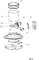
Figure 2 a filteredfan unit 20 includes a fan contained within amain body housing 22. Themain body housing 22 includes a pair ofair inlets 24 located on opposing sides of themain body housing 22. Afibre filter 26 is connected to eachinlet 24 to filter the air drawn into thefan unit 20. Thehousing 22 includes anoutlet 28 that is axially aligned with the outlet of the fan contained within thehousing 22. Aflange section 30 surrounds theoutlet 28 to which is mounted a flexible ducting (not shown). Theflange section 30 is significantly shorter than therigid ducting section 10 of the prior art as it does not house a heating element. Thefan unit 20 is configured to be mounted with the loft or roof space of a building. - A
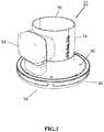
vent 32, as shown inFigure 3 , includes acylindrical body section 34 defining an airflow channel having aninlet 36 at a first end and anoutlet 38 at the opposing second end. Thefirst end 36 is configured to connect to the second end of the ducting that is connected at its first end to theflange 30 of thefan unit 20 with the ducting extending between thefan unit 20 and thevent 32 within the roof space. Thecylindrical body section 34 in use extends through an aperture formed in the ceiling of the habitable space of the building. A mountingplate 40 extends radially outwards from the second end of thebody 34 and secures the vent to the lower surface of the ceiling, internal to the habitable space via screw holes. Acover plate 44 is provided at the lower side of the mounting plate to cover and obscure the fixings of the mountingplate 40. - As shown in
Figure 4 the cover plate incudes acentral outlet aperture 48 and lateral diffusion vents 50. Aheating element 52 is located within thebody section 34. Thebody section 32 is formed in twoparts fit connectors 54 releasably connect the twobody sections aperture 56 are formed in one of thewall section 34a through which extends the connection legs of the heating element, connecting to the connection box andcontroller 58 which secured to the outer surface of thebody section 34a. Ahousing 60 is formed on the upper surface of the mounting plate for receiving the base of thecontroller 58. Thehousing 60 is open at its base with an access port extending through the mountingplate 40 to allow access to the controls of the controller from the underside of the mountingplate 40. - As shown in
Figure 5 theheating element 52 has a sinuous form to maximise the heat exchange surface area. The peripheral footprint of the heating element is designed to closely fit within the inner wall of thebody section 34 to maximise the cross sectional area of the channel across which it extends. - In an alternative embodiment shown in
Figure 6 , thebody section 134 has a single piece, cylindrical form. Thebody section 134 is formed from a section of aluminium tube. This arrangement simplifies construction, and also assists in earthing the ducting unit. A heat cut outbracket 162 is provided for mounting heat cut out devices within thebody section 134 to control theheating element 152. The heat cut outbracket 162 includes a failure cut out 166 and a control cut out 168. The failure cut out 166 comprises a bi metallic strip that is calibrated to permanently cut out and disable the heating unit in the event that a temperature is reached that indicates serious failure of the unit. This is a last resort cut out that prevents a catastrophic elevation in temperature. The control cut out is also a safety cut out, and cuts out power to the heating element in the event that the temperature exceeds a predetermined safe level. - However, the control cut out 168 is configured to re-activate the heating element once the temperature drops below the safety cut out level. The cut out bracket is also configured to support a thermistor for comfort level temperature control. This feeds back to the
control pcb 170 which controls the heating element for temperature control. Thebase pcb 172 allows remote control of the fan unit from the ceiling unit. This further embodiment also includes adamper element 174 that locates between the mounting plate 140 and the cover plate 144 to 'blank' a predetermined region of outlet to limit the direction of outlet airflow.
Claims (13)
- A heated ventilation assembly comprising:a fan (20);at least one air supply vent (32) having an outlet aperture for supplying air to a habitable space of a building;a conduit connecting the at least one vent (32) to the fan (20) and defining an airflow pathway therebetween, the fan (20) being located at a first end of the airflow pathway and arranged to supply air along the airflow pathway to the vent (32) located at the second end of the airflow pathway; anda heating element (52) located at a second end of the airflow pathway proximate the outlet aperture of the air supply vent;wherein the heating element (52) and the fan (20) are electrically connected and one of the fan (20) and the heating element (52) includes a power supply connection for connection to a power source, and the fan (20) and the heating element (52) are arranged to be powered by said power supply connection.
- A heated ventilation assembly according to claim 1 wherein the heating element (52) is mounted to the air supply vent (32) and located within the airflow pathway.
- A heated ventilation assembly according to claim 1 wherein the air supply vent (32) includes a channel section having the outlet aperture located at one end and wherein the heating element (52) is mounted to the air supply vent (32) such that it is located within the channel section.
- A heated ventilation assembly according to claim 3 wherein the air supply vent (32) comprises a mounting plate (40) surrounding the outlet aperture for securing the vent to a structure, and a wall section (34) defining the channel extending away from the mounting plate.
- A heated ventilation assembly according to claim 4 wherein the heating element (52) is mounted to the wall section (34).
- A heated ventilation assembly according to claim 5 wherein the wall section (34) is separated along its length defining two wall sections that are separable to enable installation or removal of the heating element (52) during assembly or maintenance.
- A heated ventilation assembly according to claim 6 wherein the two wall sections include cooperating fasteners (54) for releasably securing the walls sections to each other.
- A heated ventilation assembly according to any preceding claim further comprising a controller for the heating element (52), the controller being mounted to the air supply vent (32) such that it is accessible when the vent is mounted to a structure.
- A heated ventilation assembly according to claim 8 wherein the air supply vent includes comprises a mounting plate surrounding the outlet aperture for securing the vent to a structure, and a removable cover arranged to at least partially obscure the mounting plate (40) in use, and wherein the cover is also arranged to obscure the controller in normal use, the controller being accessible by removal of the removable cover.
- A heated ventilation assembly according to claim 8 wherein the controller includes a control panel and the controller extends through the mounting plate (40) such that the control panel is accessible from an underside of the mounting plate (40) in use.
- A building including a heated ventilation system for providing a ventilation airflow to a habitable space of the building, the heated ventilation system including:a fan (20) located at a location remote from the habitable space;at least one air supply vent (32) having an outlet aperture arranged to supply air to the habitable space of the building;a conduit connecting the at least one vent (32) to the fan (20) and defining an airflow pathway therebetween, the fan (20) being located at a first end of the airflow pathway and arranged to supply a ventilation airflow air along the airflow pathway to the habitable space via the vent (32) located at a second end of the airflow pathway; anda heating element (52) located at the second end of the airflow pathway proximate the outlet aperture of the air supply vent (52) and arranged to heat the ventilation airflow prior to entry into the habitable space;wherein the building includes an electrical power supply that is connected to the heating element (52), and the heating element (52) is electrically connected to the fan (20) to provide a power supply thereto such that both the heating element (52) and the fan (20) are powered via the power supply connection to the heating element.
- A building according to claim 11 wherein the fan (20) is located in a roof space of the building and the vent is located in a ceiling.
- A building according to claim 12 wherein the heating element (52) is mounted to the vent (32) and wherein part of the vent (32) is mounted to the ceiling within the habitable space, the heater including a controller that is mounted to vent (32) and which is accessible and controllable from within the habitable space.
Applications Claiming Priority (1)
| Application Number | Priority Date | Filing Date | Title |
|---|---|---|---|
| GB1510971.3AGB2539658B (en) | 2015-06-22 | 2015-06-22 | A heated ventilation assembly |
Publications (2)
| Publication Number | Publication Date |
|---|---|
| EP3109560A1 EP3109560A1 (en) | 2016-12-28 |
| EP3109560B1true EP3109560B1 (en) | 2019-04-17 |
Family
ID=53784337
Family Applications (1)
| Application Number | Title | Priority Date | Filing Date |
|---|---|---|---|
| EP16275084.8AActiveEP3109560B1 (en) | 2015-06-22 | 2016-06-22 | A heated ventilation assembly |
Country Status (2)
| Country | Link |
|---|---|
| EP (1) | EP3109560B1 (en) |
| GB (1) | GB2539658B (en) |
Families Citing this family (1)
| Publication number | Priority date | Publication date | Assignee | Title |
|---|---|---|---|---|
| DE202017102049U1 (en)* | 2017-04-06 | 2017-07-10 | Hans-Joachim Henze | Valve heating element |
Family Cites Families (6)
| Publication number | Priority date | Publication date | Assignee | Title |
|---|---|---|---|---|
| GB1006445A (en)* | 1961-10-02 | 1965-10-06 | G V Ventilation | A method of air conditioning, and an installation for carrying the method into effect |
| GB8603511D0 (en)* | 1986-02-13 | 1986-03-19 | Stukley P A R | Central heating system |
| GB2480476B (en)* | 2010-05-20 | 2016-02-03 | Dryhome Condensation Ltd | Ventilation System |
| AU2012321072A1 (en)* | 2012-01-18 | 2013-08-01 | Brivis Climate Systems Pty Ltd | An evaporative cooler arrangement |
| CN203704145U (en)* | 2013-12-09 | 2014-07-09 | 天津市和融久盛机电设备工程有限公司 | Central air conditioner cooling and heating tail end system |
| CN203837195U (en)* | 2014-03-13 | 2014-09-17 | 合肥黑马制冷设备有限公司 | Novel indoor through-the-wall type ventilating device |
- 2015
- 2015-06-22GBGB1510971.3Apatent/GB2539658B/enactiveActive
- 2016
- 2016-06-22EPEP16275084.8Apatent/EP3109560B1/enactiveActive
Non-Patent Citations (1)
| Title |
|---|
| None* |
Also Published As
| Publication number | Publication date |
|---|---|
| EP3109560A1 (en) | 2016-12-28 |
| GB2539658A (en) | 2016-12-28 |
| GB2539658B (en) | 2019-05-08 |
| GB201510971D0 (en) | 2015-08-05 |
Similar Documents
| Publication | Publication Date | Title |
|---|---|---|
| US8625976B2 (en) | In-line duct supplemental heating and cooling device and method | |
| US4003967A (en) | Electric heating and humidifying apparatus | |
| US20090140065A1 (en) | Hvac controller with save a wire terminal | |
| JP6530722B2 (en) | Ventilation air conditioning unit | |
| US20130023198A1 (en) | System and method for delivering air | |
| CN114026972A (en) | A cooling cabinet and communication equipment | |
| KR100877335B1 (en) | Air conditioner | |
| CN203372245U (en) | Fan heater of railway vehicle cab | |
| EP3109560B1 (en) | A heated ventilation assembly | |
| US20140260408A1 (en) | Compact air handler with multiple fans | |
| US6132310A (en) | Integrated heating and fresh air supply device for use with an air distribution system | |
| US20080108296A1 (en) | Fan assisted floor ventilation diffuser | |
| KR20170061136A (en) | Air conditioner base | |
| KR102055435B1 (en) | Air supply method for air conditioners | |
| US4168797A (en) | Heated air distribution system | |
| US9464816B1 (en) | Attic ventilation system | |
| US11761671B2 (en) | Compact diffuser | |
| DE102006001724A1 (en) | Solid heat exchanger structure is used in building walls to recover heat energy when air exchange is as part of climate control | |
| US20050155302A1 (en) | Modular wall panel with heated ventilator | |
| AU2020100142A4 (en) | Air-conditioning unit with modified motor bracket | |
| US8047448B1 (en) | Modular air conditioning system | |
| US20150257305A1 (en) | Tv heat shield assembly and methods of use | |
| GB2485469A (en) | Cooling heat generating equipment housed within a cabin | |
| CN209763242U (en) | Warm-air drier heater | |
| JP2013155959A (en) | Humidifying air conditioning device |
Legal Events
| Date | Code | Title | Description |
|---|---|---|---|
| PUAI | Public reference made under article 153(3) epc to a published international application that has entered the european phase | Free format text:ORIGINAL CODE: 0009012 | |
| STAA | Information on the status of an ep patent application or granted ep patent | Free format text:STATUS: THE APPLICATION HAS BEEN PUBLISHED | |
| AK | Designated contracting states | Kind code of ref document:A1 Designated state(s):AL AT BE BG CH CY CZ DE DK EE ES FI FR GB GR HR HU IE IS IT LI LT LU LV MC MK MT NL NO PL PT RO RS SE SI SK SM TR | |
| AX | Request for extension of the european patent | Extension state:BA ME | |
| STAA | Information on the status of an ep patent application or granted ep patent | Free format text:STATUS: REQUEST FOR EXAMINATION WAS MADE | |
| 17P | Request for examination filed | Effective date:20170628 | |
| RBV | Designated contracting states (corrected) | Designated state(s):AL AT BE BG CH CY CZ DE DK EE ES FI FR GB GR HR HU IE IS IT LI LT LU LV MC MK MT NL NO PL PT RO RS SE SI SK SM TR | |
| STAA | Information on the status of an ep patent application or granted ep patent | Free format text:STATUS: EXAMINATION IS IN PROGRESS | |
| 17Q | First examination report despatched | Effective date:20180208 | |
| GRAP | Despatch of communication of intention to grant a patent | Free format text:ORIGINAL CODE: EPIDOSNIGR1 | |
| STAA | Information on the status of an ep patent application or granted ep patent | Free format text:STATUS: GRANT OF PATENT IS INTENDED | |
| RIC1 | Information provided on ipc code assigned before grant | Ipc:F24H 3/04 20060101ALI20181108BHEP Ipc:F24F 7/013 20060101ALI20181108BHEP Ipc:F24F 7/06 20060101ALI20181108BHEP Ipc:F24D 5/02 20060101AFI20181108BHEP | |
| INTG | Intention to grant announced | Effective date:20181123 | |
| GRAS | Grant fee paid | Free format text:ORIGINAL CODE: EPIDOSNIGR3 | |
| GRAA | (expected) grant | Free format text:ORIGINAL CODE: 0009210 | |
| STAA | Information on the status of an ep patent application or granted ep patent | Free format text:STATUS: THE PATENT HAS BEEN GRANTED | |
| AK | Designated contracting states | Kind code of ref document:B1 Designated state(s):AL AT BE BG CH CY CZ DE DK EE ES FI FR GB GR HR HU IE IS IT LI LT LU LV MC MK MT NL NO PL PT RO RS SE SI SK SM TR | |
| REG | Reference to a national code | Ref country code:GB Ref legal event code:FG4D | |
| REG | Reference to a national code | Ref country code:CH Ref legal event code:EP | |
| REG | Reference to a national code | Ref country code:DE Ref legal event code:R096 Ref document number:602016012522 Country of ref document:DE | |
| REG | Reference to a national code | Ref country code:AT Ref legal event code:REF Ref document number:1121967 Country of ref document:AT Kind code of ref document:T Effective date:20190515 Ref country code:IE Ref legal event code:FG4D | |
| REG | Reference to a national code | Ref country code:NL Ref legal event code:FP | |
| REG | Reference to a national code | Ref country code:LT Ref legal event code:MG4D | |
| PG25 | Lapsed in a contracting state [announced via postgrant information from national office to epo] | Ref country code:AL Free format text:LAPSE BECAUSE OF FAILURE TO SUBMIT A TRANSLATION OF THE DESCRIPTION OR TO PAY THE FEE WITHIN THE PRESCRIBED TIME-LIMIT Effective date:20190417 Ref country code:PT Free format text:LAPSE BECAUSE OF FAILURE TO SUBMIT A TRANSLATION OF THE DESCRIPTION OR TO PAY THE FEE WITHIN THE PRESCRIBED TIME-LIMIT Effective date:20190817 Ref country code:NO Free format text:LAPSE BECAUSE OF FAILURE TO SUBMIT A TRANSLATION OF THE DESCRIPTION OR TO PAY THE FEE WITHIN THE PRESCRIBED TIME-LIMIT Effective date:20190717 Ref country code:FI Free format text:LAPSE BECAUSE OF FAILURE TO SUBMIT A TRANSLATION OF THE DESCRIPTION OR TO PAY THE FEE WITHIN THE PRESCRIBED TIME-LIMIT Effective date:20190417 Ref country code:SE Free format text:LAPSE BECAUSE OF FAILURE TO SUBMIT A TRANSLATION OF THE DESCRIPTION OR TO PAY THE FEE WITHIN THE PRESCRIBED TIME-LIMIT Effective date:20190417 Ref country code:HR Free format text:LAPSE BECAUSE OF FAILURE TO SUBMIT A TRANSLATION OF THE DESCRIPTION OR TO PAY THE FEE WITHIN THE PRESCRIBED TIME-LIMIT Effective date:20190417 Ref country code:ES Free format text:LAPSE BECAUSE OF FAILURE TO SUBMIT A TRANSLATION OF THE DESCRIPTION OR TO PAY THE FEE WITHIN THE PRESCRIBED TIME-LIMIT Effective date:20190417 Ref country code:LT Free format text:LAPSE BECAUSE OF FAILURE TO SUBMIT A TRANSLATION OF THE DESCRIPTION OR TO PAY THE FEE WITHIN THE PRESCRIBED TIME-LIMIT Effective date:20190417 | |
| PG25 | Lapsed in a contracting state [announced via postgrant information from national office to epo] | Ref country code:RS Free format text:LAPSE BECAUSE OF FAILURE TO SUBMIT A TRANSLATION OF THE DESCRIPTION OR TO PAY THE FEE WITHIN THE PRESCRIBED TIME-LIMIT Effective date:20190417 Ref country code:GR Free format text:LAPSE BECAUSE OF FAILURE TO SUBMIT A TRANSLATION OF THE DESCRIPTION OR TO PAY THE FEE WITHIN THE PRESCRIBED TIME-LIMIT Effective date:20190718 Ref country code:BG Free format text:LAPSE BECAUSE OF FAILURE TO SUBMIT A TRANSLATION OF THE DESCRIPTION OR TO PAY THE FEE WITHIN THE PRESCRIBED TIME-LIMIT Effective date:20190717 Ref country code:LV Free format text:LAPSE BECAUSE OF FAILURE TO SUBMIT A TRANSLATION OF THE DESCRIPTION OR TO PAY THE FEE WITHIN THE PRESCRIBED TIME-LIMIT Effective date:20190417 Ref country code:PL Free format text:LAPSE BECAUSE OF FAILURE TO SUBMIT A TRANSLATION OF THE DESCRIPTION OR TO PAY THE FEE WITHIN THE PRESCRIBED TIME-LIMIT Effective date:20190417 | |
| REG | Reference to a national code | Ref country code:AT Ref legal event code:MK05 Ref document number:1121967 Country of ref document:AT Kind code of ref document:T Effective date:20190417 | |
| PG25 | Lapsed in a contracting state [announced via postgrant information from national office to epo] | Ref country code:IS Free format text:LAPSE BECAUSE OF FAILURE TO SUBMIT A TRANSLATION OF THE DESCRIPTION OR TO PAY THE FEE WITHIN THE PRESCRIBED TIME-LIMIT Effective date:20190817 | |
| REG | Reference to a national code | Ref country code:DE Ref legal event code:R097 Ref document number:602016012522 Country of ref document:DE | |
| PG25 | Lapsed in a contracting state [announced via postgrant information from national office to epo] | Ref country code:CZ Free format text:LAPSE BECAUSE OF FAILURE TO SUBMIT A TRANSLATION OF THE DESCRIPTION OR TO PAY THE FEE WITHIN THE PRESCRIBED TIME-LIMIT Effective date:20190417 Ref country code:RO Free format text:LAPSE BECAUSE OF FAILURE TO SUBMIT A TRANSLATION OF THE DESCRIPTION OR TO PAY THE FEE WITHIN THE PRESCRIBED TIME-LIMIT Effective date:20190417 Ref country code:SK Free format text:LAPSE BECAUSE OF FAILURE TO SUBMIT A TRANSLATION OF THE DESCRIPTION OR TO PAY THE FEE WITHIN THE PRESCRIBED TIME-LIMIT Effective date:20190417 Ref country code:DK Free format text:LAPSE BECAUSE OF FAILURE TO SUBMIT A TRANSLATION OF THE DESCRIPTION OR TO PAY THE FEE WITHIN THE PRESCRIBED TIME-LIMIT Effective date:20190417 Ref country code:EE Free format text:LAPSE BECAUSE OF FAILURE TO SUBMIT A TRANSLATION OF THE DESCRIPTION OR TO PAY THE FEE WITHIN THE PRESCRIBED TIME-LIMIT Effective date:20190417 Ref country code:AT Free format text:LAPSE BECAUSE OF FAILURE TO SUBMIT A TRANSLATION OF THE DESCRIPTION OR TO PAY THE FEE WITHIN THE PRESCRIBED TIME-LIMIT Effective date:20190417 Ref country code:MC Free format text:LAPSE BECAUSE OF FAILURE TO SUBMIT A TRANSLATION OF THE DESCRIPTION OR TO PAY THE FEE WITHIN THE PRESCRIBED TIME-LIMIT Effective date:20190417 | |
| REG | Reference to a national code | Ref country code:CH Ref legal event code:PL | |
| PLBE | No opposition filed within time limit | Free format text:ORIGINAL CODE: 0009261 | |
| STAA | Information on the status of an ep patent application or granted ep patent | Free format text:STATUS: NO OPPOSITION FILED WITHIN TIME LIMIT | |
| PG25 | Lapsed in a contracting state [announced via postgrant information from national office to epo] | Ref country code:IT Free format text:LAPSE BECAUSE OF FAILURE TO SUBMIT A TRANSLATION OF THE DESCRIPTION OR TO PAY THE FEE WITHIN THE PRESCRIBED TIME-LIMIT Effective date:20190417 Ref country code:SM Free format text:LAPSE BECAUSE OF FAILURE TO SUBMIT A TRANSLATION OF THE DESCRIPTION OR TO PAY THE FEE WITHIN THE PRESCRIBED TIME-LIMIT Effective date:20190417 | |
| 26N | No opposition filed | Effective date:20200120 | |
| PG25 | Lapsed in a contracting state [announced via postgrant information from national office to epo] | Ref country code:TR Free format text:LAPSE BECAUSE OF FAILURE TO SUBMIT A TRANSLATION OF THE DESCRIPTION OR TO PAY THE FEE WITHIN THE PRESCRIBED TIME-LIMIT Effective date:20190417 | |
| PG25 | Lapsed in a contracting state [announced via postgrant information from national office to epo] | Ref country code:SI Free format text:LAPSE BECAUSE OF FAILURE TO SUBMIT A TRANSLATION OF THE DESCRIPTION OR TO PAY THE FEE WITHIN THE PRESCRIBED TIME-LIMIT Effective date:20190417 Ref country code:LU Free format text:LAPSE BECAUSE OF NON-PAYMENT OF DUE FEES Effective date:20190622 Ref country code:LI Free format text:LAPSE BECAUSE OF NON-PAYMENT OF DUE FEES Effective date:20190630 Ref country code:CH Free format text:LAPSE BECAUSE OF NON-PAYMENT OF DUE FEES Effective date:20190630 | |
| REG | Reference to a national code | Ref country code:DE Ref legal event code:R081 Ref document number:602016012522 Country of ref document:DE Owner name:POLYPIPE LIMITED, EDLINGTON, GB Free format text:FORMER OWNER: NUAIRE LIMITED, CAERPHILLY, MID GLAMORGAN, GB | |
| GBPC | Gb: european patent ceased through non-payment of renewal fee | Effective date:20200622 | |
| PG25 | Lapsed in a contracting state [announced via postgrant information from national office to epo] | Ref country code:GB Free format text:LAPSE BECAUSE OF NON-PAYMENT OF DUE FEES Effective date:20200622 | |
| PG25 | Lapsed in a contracting state [announced via postgrant information from national office to epo] | Ref country code:CY Free format text:LAPSE BECAUSE OF FAILURE TO SUBMIT A TRANSLATION OF THE DESCRIPTION OR TO PAY THE FEE WITHIN THE PRESCRIBED TIME-LIMIT Effective date:20190417 | |
| PG25 | Lapsed in a contracting state [announced via postgrant information from national office to epo] | Ref country code:HU Free format text:LAPSE BECAUSE OF FAILURE TO SUBMIT A TRANSLATION OF THE DESCRIPTION OR TO PAY THE FEE WITHIN THE PRESCRIBED TIME-LIMIT; INVALID AB INITIO Effective date:20160622 Ref country code:MT Free format text:LAPSE BECAUSE OF FAILURE TO SUBMIT A TRANSLATION OF THE DESCRIPTION OR TO PAY THE FEE WITHIN THE PRESCRIBED TIME-LIMIT Effective date:20190417 | |
| PG25 | Lapsed in a contracting state [announced via postgrant information from national office to epo] | Ref country code:MK Free format text:LAPSE BECAUSE OF FAILURE TO SUBMIT A TRANSLATION OF THE DESCRIPTION OR TO PAY THE FEE WITHIN THE PRESCRIBED TIME-LIMIT Effective date:20190417 | |
| PGFP | Annual fee paid to national office [announced via postgrant information from national office to epo] | Ref country code:DE Payment date:20240628 Year of fee payment:9 | |
| PGFP | Annual fee paid to national office [announced via postgrant information from national office to epo] | Ref country code:NL Payment date:20250627 Year of fee payment:10 Ref country code:BE Payment date:20250627 Year of fee payment:10 | |
| PGFP | Annual fee paid to national office [announced via postgrant information from national office to epo] | Ref country code:FR Payment date:20250626 Year of fee payment:10 | |
| PGFP | Annual fee paid to national office [announced via postgrant information from national office to epo] | Ref country code:IE Payment date:20250627 Year of fee payment:10 |