EP3108809A1 - Method and device for measuring pressure on a patient's heart - Google Patents
Method and device for measuring pressure on a patient's heartDownload PDFInfo
- Publication number
- EP3108809A1 EP3108809A1EP15173069.4AEP15173069AEP3108809A1EP 3108809 A1EP3108809 A1EP 3108809A1EP 15173069 AEP15173069 AEP 15173069AEP 3108809 A1EP3108809 A1EP 3108809A1
- Authority
- EP
- European Patent Office
- Prior art keywords
- heart
- pump
- pressure
- sensor
- thorax
- Prior art date
- Legal status (The legal status is an assumption and is not a legal conclusion. Google has not performed a legal analysis and makes no representation as to the accuracy of the status listed.)
- Withdrawn
Links
Images


Classifications
- A—HUMAN NECESSITIES
- A61—MEDICAL OR VETERINARY SCIENCE; HYGIENE
- A61B—DIAGNOSIS; SURGERY; IDENTIFICATION
- A61B5/00—Measuring for diagnostic purposes; Identification of persons
- A61B5/02—Detecting, measuring or recording for evaluating the cardiovascular system, e.g. pulse, heart rate, blood pressure or blood flow
- A61B5/021—Measuring pressure in heart or blood vessels
- A61B5/0215—Measuring pressure in heart or blood vessels by means inserted into the body
- A61B5/02158—Measuring pressure in heart or blood vessels by means inserted into the body provided with two or more sensor elements
- A—HUMAN NECESSITIES
- A61—MEDICAL OR VETERINARY SCIENCE; HYGIENE
- A61B—DIAGNOSIS; SURGERY; IDENTIFICATION
- A61B5/00—Measuring for diagnostic purposes; Identification of persons
- A61B5/07—Endoradiosondes
- A61B5/076—Permanent implantation
- A—HUMAN NECESSITIES
- A61—MEDICAL OR VETERINARY SCIENCE; HYGIENE
- A61B—DIAGNOSIS; SURGERY; IDENTIFICATION
- A61B5/00—Measuring for diagnostic purposes; Identification of persons
- A61B5/48—Other medical applications
- A61B5/4836—Diagnosis combined with treatment in closed-loop systems or methods
- A—HUMAN NECESSITIES
- A61—MEDICAL OR VETERINARY SCIENCE; HYGIENE
- A61B—DIAGNOSIS; SURGERY; IDENTIFICATION
- A61B5/00—Measuring for diagnostic purposes; Identification of persons
- A61B5/68—Arrangements of detecting, measuring or recording means, e.g. sensors, in relation to patient
- A61B5/6846—Arrangements of detecting, measuring or recording means, e.g. sensors, in relation to patient specially adapted to be brought in contact with an internal body part, i.e. invasive
- A61B5/6847—Arrangements of detecting, measuring or recording means, e.g. sensors, in relation to patient specially adapted to be brought in contact with an internal body part, i.e. invasive mounted on an invasive device
- A61B5/686—Permanently implanted devices, e.g. pacemakers, other stimulators, biochips
- A—HUMAN NECESSITIES
- A61—MEDICAL OR VETERINARY SCIENCE; HYGIENE
- A61M—DEVICES FOR INTRODUCING MEDIA INTO, OR ONTO, THE BODY; DEVICES FOR TRANSDUCING BODY MEDIA OR FOR TAKING MEDIA FROM THE BODY; DEVICES FOR PRODUCING OR ENDING SLEEP OR STUPOR
- A61M60/00—Blood pumps; Devices for mechanical circulatory actuation; Balloon pumps for circulatory assistance
- A61M60/10—Location thereof with respect to the patient's body
- A61M60/122—Implantable pumps or pumping devices, i.e. the blood being pumped inside the patient's body
- A61M60/126—Implantable pumps or pumping devices, i.e. the blood being pumped inside the patient's body implantable via, into, inside, in line, branching on, or around a blood vessel
- A61M60/148—Implantable pumps or pumping devices, i.e. the blood being pumped inside the patient's body implantable via, into, inside, in line, branching on, or around a blood vessel in line with a blood vessel using resection or like techniques, e.g. permanent endovascular heart assist devices
- A—HUMAN NECESSITIES
- A61—MEDICAL OR VETERINARY SCIENCE; HYGIENE
- A61M—DEVICES FOR INTRODUCING MEDIA INTO, OR ONTO, THE BODY; DEVICES FOR TRANSDUCING BODY MEDIA OR FOR TAKING MEDIA FROM THE BODY; DEVICES FOR PRODUCING OR ENDING SLEEP OR STUPOR
- A61M60/00—Blood pumps; Devices for mechanical circulatory actuation; Balloon pumps for circulatory assistance
- A61M60/10—Location thereof with respect to the patient's body
- A61M60/122—Implantable pumps or pumping devices, i.e. the blood being pumped inside the patient's body
- A61M60/165—Implantable pumps or pumping devices, i.e. the blood being pumped inside the patient's body implantable in, on, or around the heart
- A61M60/178—Implantable pumps or pumping devices, i.e. the blood being pumped inside the patient's body implantable in, on, or around the heart drawing blood from a ventricle and returning the blood to the arterial system via a cannula external to the ventricle, e.g. left or right ventricular assist devices
- A—HUMAN NECESSITIES
- A61—MEDICAL OR VETERINARY SCIENCE; HYGIENE
- A61M—DEVICES FOR INTRODUCING MEDIA INTO, OR ONTO, THE BODY; DEVICES FOR TRANSDUCING BODY MEDIA OR FOR TAKING MEDIA FROM THE BODY; DEVICES FOR PRODUCING OR ENDING SLEEP OR STUPOR
- A61M60/00—Blood pumps; Devices for mechanical circulatory actuation; Balloon pumps for circulatory assistance
- A61M60/20—Type thereof
- A61M60/205—Non-positive displacement blood pumps
- A61M60/216—Non-positive displacement blood pumps including a rotating member acting on the blood, e.g. impeller
- A61M60/226—Non-positive displacement blood pumps including a rotating member acting on the blood, e.g. impeller the blood flow through the rotating member having mainly radial components
- A61M60/232—Centrifugal pumps
- A—HUMAN NECESSITIES
- A61—MEDICAL OR VETERINARY SCIENCE; HYGIENE
- A61M—DEVICES FOR INTRODUCING MEDIA INTO, OR ONTO, THE BODY; DEVICES FOR TRANSDUCING BODY MEDIA OR FOR TAKING MEDIA FROM THE BODY; DEVICES FOR PRODUCING OR ENDING SLEEP OR STUPOR
- A61M60/00—Blood pumps; Devices for mechanical circulatory actuation; Balloon pumps for circulatory assistance
- A61M60/20—Type thereof
- A61M60/205—Non-positive displacement blood pumps
- A61M60/216—Non-positive displacement blood pumps including a rotating member acting on the blood, e.g. impeller
- A61M60/237—Non-positive displacement blood pumps including a rotating member acting on the blood, e.g. impeller the blood flow through the rotating member having mainly axial components, e.g. axial flow pumps
- A—HUMAN NECESSITIES
- A61—MEDICAL OR VETERINARY SCIENCE; HYGIENE
- A61M—DEVICES FOR INTRODUCING MEDIA INTO, OR ONTO, THE BODY; DEVICES FOR TRANSDUCING BODY MEDIA OR FOR TAKING MEDIA FROM THE BODY; DEVICES FOR PRODUCING OR ENDING SLEEP OR STUPOR
- A61M60/00—Blood pumps; Devices for mechanical circulatory actuation; Balloon pumps for circulatory assistance
- A61M60/40—Details relating to driving
- A61M60/403—Details relating to driving for non-positive displacement blood pumps
- A61M60/422—Details relating to driving for non-positive displacement blood pumps the force acting on the blood contacting member being electromagnetic, e.g. using canned motor pumps
- A—HUMAN NECESSITIES
- A61—MEDICAL OR VETERINARY SCIENCE; HYGIENE
- A61M—DEVICES FOR INTRODUCING MEDIA INTO, OR ONTO, THE BODY; DEVICES FOR TRANSDUCING BODY MEDIA OR FOR TAKING MEDIA FROM THE BODY; DEVICES FOR PRODUCING OR ENDING SLEEP OR STUPOR
- A61M60/00—Blood pumps; Devices for mechanical circulatory actuation; Balloon pumps for circulatory assistance
- A61M60/50—Details relating to control
- A61M60/508—Electronic control means, e.g. for feedback regulation
- A61M60/515—Regulation using real-time patient data
- A61M60/531—Regulation using real-time patient data using blood pressure data, e.g. from blood pressure sensors
- A—HUMAN NECESSITIES
- A61—MEDICAL OR VETERINARY SCIENCE; HYGIENE
- A61M—DEVICES FOR INTRODUCING MEDIA INTO, OR ONTO, THE BODY; DEVICES FOR TRANSDUCING BODY MEDIA OR FOR TAKING MEDIA FROM THE BODY; DEVICES FOR PRODUCING OR ENDING SLEEP OR STUPOR
- A61M60/00—Blood pumps; Devices for mechanical circulatory actuation; Balloon pumps for circulatory assistance
- A61M60/80—Constructional details other than related to driving
- A61M60/802—Constructional details other than related to driving of non-positive displacement blood pumps
- A61M60/81—Pump housings
- A61M60/816—Sensors arranged on or in the housing, e.g. ultrasound flow sensors
- A—HUMAN NECESSITIES
- A61—MEDICAL OR VETERINARY SCIENCE; HYGIENE
- A61B—DIAGNOSIS; SURGERY; IDENTIFICATION
- A61B2560/00—Constructional details of operational features of apparatus; Accessories for medical measuring apparatus
- A61B2560/02—Operational features
- A61B2560/0204—Operational features of power management
- A61B2560/0214—Operational features of power management of power generation or supply
- A61B2560/0219—Operational features of power management of power generation or supply of externally powered implanted units
- A—HUMAN NECESSITIES
- A61—MEDICAL OR VETERINARY SCIENCE; HYGIENE
- A61B—DIAGNOSIS; SURGERY; IDENTIFICATION
- A61B2562/00—Details of sensors; Constructional details of sensor housings or probes; Accessories for sensors
- A61B2562/02—Details of sensors specially adapted for in-vivo measurements
- A61B2562/0247—Pressure sensors
- A—HUMAN NECESSITIES
- A61—MEDICAL OR VETERINARY SCIENCE; HYGIENE
- A61B—DIAGNOSIS; SURGERY; IDENTIFICATION
- A61B2562/00—Details of sensors; Constructional details of sensor housings or probes; Accessories for sensors
- A61B2562/16—Details of sensor housings or probes; Details of structural supports for sensors
- A61B2562/168—Fluid filled sensor housings
- A—HUMAN NECESSITIES
- A61—MEDICAL OR VETERINARY SCIENCE; HYGIENE
- A61B—DIAGNOSIS; SURGERY; IDENTIFICATION
- A61B5/00—Measuring for diagnostic purposes; Identification of persons
- A61B5/0002—Remote monitoring of patients using telemetry, e.g. transmission of vital signals via a communication network
- A61B5/0031—Implanted circuitry
- A—HUMAN NECESSITIES
- A61—MEDICAL OR VETERINARY SCIENCE; HYGIENE
- A61M—DEVICES FOR INTRODUCING MEDIA INTO, OR ONTO, THE BODY; DEVICES FOR TRANSDUCING BODY MEDIA OR FOR TAKING MEDIA FROM THE BODY; DEVICES FOR PRODUCING OR ENDING SLEEP OR STUPOR
- A61M2205/00—General characteristics of the apparatus
- A61M2205/33—Controlling, regulating or measuring
- A61M2205/3331—Pressure; Flow
- A—HUMAN NECESSITIES
- A61—MEDICAL OR VETERINARY SCIENCE; HYGIENE
- A61M—DEVICES FOR INTRODUCING MEDIA INTO, OR ONTO, THE BODY; DEVICES FOR TRANSDUCING BODY MEDIA OR FOR TAKING MEDIA FROM THE BODY; DEVICES FOR PRODUCING OR ENDING SLEEP OR STUPOR
- A61M2230/00—Measuring parameters of the user
- A61M2230/30—Blood pressure
Definitions
- the inventionis in the field of mechanics and electrical engineering and can be used with particular advantage in the field of medical technology. It specifically addresses pressure measurement on the heart of a patient using sensor devices.
- a variety of medical deviceshave been developed which are used to monitor or assist patients and which may be implanted in the patient's body in whole or in part. These include, for example, pacemakers, defibrillators and cardiac assist systems in the form of fully or partially implanted cardiac pumps.
- monitoring the fluid pressure inside the heartis important.
- the present inventionis based on the background of the prior art the object to provide a device for measuring pressure on the heart of a patient, the measurement of a corrected pressure in connection with the operation of a device connected to the heart of the patient in more efficient, simplest possible , cheaper and for the patient as little burdening way allowed.
- the objectis achieved with the features of claim 1.
- the claims 2 to 11call specific embodiments of the solution.
- the claim 12relates to a method for solving the problem, the claim 13 to a computer program product and the claims 14 and 15 to a control device.
- a device for pressure measurement at the heart of a patientcharacterized by a sensor device which detects the pressure difference between a point within the heart on the one hand and the outside of the heart within the thorax lying space on the other hand.
- at least one element of the sensor devicecan be arranged on a device connected to the heart, in particular a heart pump, a pacemaker or defibrillator.
- the present solutionallows the measurement of the transmural pressure and thus an improved control of the device connected to the heart, such as a heart pump, a pacemaker or a defibrillator.
- the sensor devicecan be connected both to the space inside the heart / heart wall and to the space outside the heart in the pericardium or in the thorax.
- the connectioncan, as will be explained in more detail below, be realized electrically or hydraulically (by means of a fluid channel) or via another type of communication.
- the connection of at least one part of the sensor device to a deviceis advantageous, so that the expense in the production and also in the implantation of the overall assembly is optimized. Sources of error in operation can be minimized and a reliable placement in the patient's body can be achieved.
- At least one sensor of the sensor device and possibly also a fluid channel, with which the sensor is connected or in which it is arranged,can be firmly connected to or attached to a device, such as a heart pump.
- An embodiment of the solutionmay for example provide that at least one element of the sensor device is arranged on a device connected to the heart, in particular a heart pump.
- the sensor devicehas only a single pressure sensor in the form of a pressure difference sensor.
- Thismay, for example, have a measuring diaphragm, the pressure on the inside of the heart being present on a first side of the diaphragm, while the pressure on the second side of the diaphragm is present from the thorax region.
- a membrane or sensor devicecan close immediately a continuous opening in the heart wall or be provided within the heart wall.
- differential pressure sensorcan also be connected on one or both sides of the membrane in each case by means of a fluid channel with the heart interior on the one hand and the pericardium or the thorax on the other hand, so act on the differential pressure measuring element, in particular the membrane, the two to be compared pressures.
- the corresponding fluid channelsmay be formed by solid tubular elements or cannulas or catheters. They can also be formed by bores and / or channels within a solid body, for example a housing of a device, for example in or on a heart pump.
- a further embodiment of the solutioncan also provide, for example, that the differential pressure sensor is connected on the one hand to a region within the pump or in its intake region or its discharge region and on the other hand to a region outside the pump housing.
- a measurementbasically means that a differential pressure between the interior of the pump, either in the intake or in the discharge area, on the one hand and outside the pump in the thorax on the other hand is measured.
- the pressure difference between the suction and discharge areas created by the operation of the pumpcan be taken into account in the determination of the pressure in the blood vessels and in the heart. This results in a particularly favorable arrangement of all channels on such a pump or in the area of Pump in its interior and on its outer side, so that the overall arrangement, formed from the sensor device and such a heart pump, is particularly inexpensive to manufacture, implant and operate.
- a further embodiment of the solutionmay provide that the channel extends through the interior of a pump housing and is at least partially, in particular sections, surrounded on all sides by the pumped blood through the pump. If such a channel runs inside a pump, the arrangement is particularly space-saving and less prone.
- there are problems of space within the pump housing to solvebecause there, for example, moving parts need space and must not be hindered by the channel.
- Particular problemsmay arise, for example, in the use of axially conveying rotor pumps, since in such pumps most of the interior of the pump housing is swept over during the rotation of the conveyor rotor.
- Such a pumpcan, for example, also suck blood in the axial direction and convey it in the radial direction.
- a fluid channel on the housing wallcan run separately from the pump interior or be introduced as a bore in the wall of the pump housing.
- the solutioncan also be configured in that the sensor device comprises two absolute pressure sensors, the first of which is arranged inside the heart or connected to the interior of the heart via a fluid channel and the second outside of the heart in the thorax or with an area outside Heart is connected in the thorax via a fluid channel and which are connected to a device for differential pressure determination.
- the absolute pressure sensorscan be attached to the housing of the device and measure the pressure outside or inside the housing.
- an absolute pressure sensorcan be used, for example, in the case of an off-heart part of the pump housing arranged on the outside of the housing and also optionally be attached to this and communicate with the pericardium or the thorax outside the pericardium directly or by means of a fluid channel.
- Such an absolute pressure sensorcan also be arranged in the interior of the pump housing and communicate with the corresponding areas outside the heart by means of a channel running through the wall of the pump housing.
- An absolute pressure sensormay also be fixedly disposed inside the heart on the outside or inside of the pump housing and connected to the housing.
- the device for differential pressure determinationis arranged outside the heart in the thorax or outside the patient's body.
- the sensorsare connected to a radio device for the transmission of measured values or to an electrical line passing through the heart wall.
- the sensorscan also be designed as passive, funkabfragbare surface wave sensors in the form of a transponder.
- the pressure difference between the determined measured values of both pressure sensorsis to be determined, these measured values can first be transmitted to a device for detecting pressure difference.
- the transmission of the valuescan be done electrically or by means of a radio transmission or other non-physically bound transmission method.
- the pressure difference determination devicecan then perform a difference formation in an analog or digital manner and provide the pressure difference value or transmit it directly to a control device of the device, in particular the heart pump.
- the controller of the devicecan also take over directly the pressure difference determination.
- the solution of the problemfurther relates to a method for controlling or regulating an aggregate in a patient's body under consideration a pressure detected in the heart of the patient, wherein the pressure is detected as a differential pressure between the interior of the heart and the area outside the heart in the thorax and is based on the control or regulation.
- the device described abovecan be used, in particular in conjunction with the control device of an implanted device, such as a heart pump, a pacemaker or a defibrillator.
- an implanted devicesuch as a heart pump, a pacemaker or a defibrillator.
- the solutionrelates to a computer program product having a computer program for controlling an aggregate in a patient's body, taking into account a pressure detected in the heart of the patient, the pressure being determined as the differential pressure between the interior of the heart and the area outside the heart in the thorax and used in the computer program as a parameter.
- a computer programis used to operate, for example, a microcontroller that performs processing of the acquired measurement data.
- the programcan also be operated as a subprogram or program module in the operation of a control unit of a corresponding unit, such as a heart pump.
- a control device for regulating a cardiac pumpmay also be provided, in which parameters such as e.g. Filling pressures of the heart based on the pressure difference between the pressure inside the heart and outside the heart in the thorax, determined by a device according to one of claims 1 to 11, are used and in which the delivery rate of the pump serves as a manipulated variable.
- the solution in connection with a cardiac pacemakermay also provide a controller for regulating a cardiac pacemaker, in which parameters such as heart pressure pressures based on the pressure difference between the heart interior and the space outside the heart in the thorax, determined by a device according to one of the claims 1 to 11, are used and in which serves as a target size of the scheme, the flow rate of the heart.
- FIG. 1schematically shows the body 1 of a patient, wherein separately and schematically the heart 2 is shown with an implanted heart pump 3.
- the heart pump 3has a rotor which is rotatable about the axis 4 and thereby promotes blood into a catheter 5.
- the pump 3sucks through an intake 6, which passes through a wall of the heart 2, blood from the interior of the heart, for example from an atrium or a ventricle, and promotes this via the cannula / catheter 5 in a blood vessel.
- control unit 7which controls the pump 3, for example by means of electrical signals.
- the pump 3is driven by an electric motor with windings and magnets.
- the motormay be a brushless, for example in the pulse width modulation method controlled electric motor.
- the rotor of the pump 3may be formed as a radial rotor which accelerates axially flowing fluid in the radial direction. In a radially outer collecting space, the pumped fluid / blood is then collected and passed radially outward into the cannula 5 by the pressure generated.
- the consideration of the pressure conditions in the heart 2is important in comparison to the pressure prevailing in the thorax 8 outside the heart.
- the differential pressure between the space inside the heart 2 and the thorax 8is measured by a sensor device, which will be discussed in more detail below.
- FIG. 2schematically shows in a cross section the heart 2 of the patient, which is shown here only as a cavity and is located in the thorax 8. It is a heart pump 3 'is provided, which is designed as an axially pumping pump with a rotor 9.
- the pumpdelivers blood from inside the heart 2 in the direction of the arrow 10, sucks it out of the heart through the suction cannula 11 and expels it through the outflow cannula 12 in the direction of a blood vessel, not shown.
- at least two sensors of a sensor devicecan be provided. In FIG. 2 a total of three sensors are shown, the sensors 13, 14 are intended as alternatives and each measure the pressure inside the heart.
- the senor 13is arranged directly in the heart, while the sensor 14 is connected in the interior of the pump through the intake 11 to the interior of the heart and, if it is apart from flow resistance, directly measures the pressure inside the heart.
- the sensor 15is arranged outside the pump 3 'in the thorax 8 and measures the pressure there.
- the three sensors 13, 14, 15are each equipped with radio devices or induction coils, which allow them to send detected measured values to a device 16 for determining the pressure difference.
- the device 16may for example be designed as a microcontroller and be equipped with a receiver for receiving the measured data.
- a computer program running on the microcontrollerdetects the pressure differential detected by the various sensors 13, 14, 15 of the sensor device becomes. This can then be forwarded to a control device of the pump 3 '.
- the sensors 13, 14, 15are arranged and attached directly to the heart pump 3 'or to the intake 11 of the pump. They may be attached to the outside of the pump housing, such as the sensor 15, but also, like the sensor 14, inside the pump chamber on the inside of the housing.
- FIG. 3a pacemaker 17 is shown implanted in the thorax 8 of a patient.
- the pacemaker 17is connected by means of various lines 18, 19, 20 with electrodes which lie directly against the heart wall of the heart 2.
- two sensors 21, 22are provided, wherein the first sensor 21 is arranged inside the heart 2 and connected to the pacemaker 17 by means of an electrical line 23 is.
- the sensor 22is attached externally to the housing on the pacemaker 17 outside and serves to measure the pressure in the thorax. Both sensors 21, 22 are connected by means of lines to a differential pressure detecting device 24 which is integrated into the pacemaker 17. The determined differential pressure can thus be used within various algorithms of the pacemaker 17.
- FIG. 4schematically shows the heart 2 of a patient with two alternatively usable units, each of which allow for a differential pressure determination.
- a pacemaker 17is shown only schematically as a box. Fixed to this is a differential pressure sensor 25, which provides a separation membrane 27 in a measuring space 26.
- the first compartment 28 on the side 2 of the membrane 27 facing the heartis connected to the interior of the heart via a cannula 29.
- the second subspace 30, which lies on the side of the membrane 27 facing away from the heart 2is connected to the interior of the thorax 8 by means of a cannula 31.
- the membrane position of the elastic, deflectable membrane 27directly indicates the pressure difference between the interior of the heart 2 and the thorax. This is detected and evaluated by a sensor and microcontroller 32 and supplied as a value of the pressure difference directly to the control unit 33. This in turn can act on the pacemaker 17 and be associated with this.
- a heart pump 3which is designed as an axial / radial pump and has an intake 6, which protrudes through the heart wall of the heart 2 and is fitted tightly into the opening of the heart wall.
- a first sensor 34is arranged, which communicates with the interior of the heart 2 via the interior of the intake manifold 6 and measures the absolute pressure prevailing there.
- a sensor 35is arranged on the outside of the pump 3, which detects the absolute pressure in the vicinity of the pump 3, ie in the thorax. Both sensors 34, 35 are connected via radio or via an electrical line to a differential pressure detecting device 36, which determines the differential pressure between heart heart and thorax.
- FIG. 5an axial / radial pump 3 is shown in more detail by way of example.
- the pumphas a housing 37 with an intake 6, which passes through the wall of the heart 2.
- an inflow / suction channel 6 'is formed, is sucked by the blood in the direction of arrows 38, 39.
- the pump motorhas an internal stator 40, on which the rotor 41 can be mounted hydrostatically and / or magnetically as well as in the radial direction as well as in the axial direction.
- the pump motormay be designed as a brushless electric motor.
- flow channels for the bloodare integrated, which can flow in the axial direction and eject by centrifugal action in the radial direction.
- annular collecting space 42is formed in the housing 37, in which the blood collects and flows in the circumferential direction up to an outflow opening 43, from where it is moved further into a Ausströmkanüle.
- a differential pressure sensor 44is shown with a membrane 45, wherein the sensor communicates on the one hand via a channel 46 in the stator with the suction of the pump in the intake and on the other hand with the pump exterior via a fluid channel 47.
- the differential pressureis evaluated in an evaluation device 48 and forwarded accordingly to an aggregate.
- the second differential pressure devicewhich is alternatively conceivable on such a pump, has a differential pressure sensor 49 with a membrane 50 and an evaluation device 51.
- the sensor 49is connected on one side of the membrane 50 via a channel 52 with the heart interior, which runs in or on the housing 37 parallel to the suction channel 6 '.
- the channel 52may be formed by a bent tube placed externally on the housing 37 or by a bore in the wall of the housing 37 or else by a tube running on the inner wall of the housing 37.
- the sensor 49communicates on the other side of the membrane via a cannula 53 with the outer environment of the pump housing 37 in the thorax.
- the differential pressure determining device 51communicates with an aggregate 54.
- an axial pump 55is shown with a partially cylindrical housing 56 in which a rotor 57 is rotatably mounted.
- the rotor 57has a hub 58 with conveying elements 59.
- the hub 58is rotatably mounted in two bearings 60, 61 and usually driven by a motor or a flexible shaft, which is not shown in the figure.
- the flexible shaftusually protrudes through the outflow opening 62 of the housing 56.
- the inflow openingis designated 63.
- a channel 64is connected, which extends on the outside of the wall of the housing 56 and leads to a first partial space 65 on one side of the diaphragm 66 of a differential pressure sensor 67.
- the second partial space 68 of the differential pressure sensor 67is connected via an opening and / or a fluid channel with the outer environment of the pump housing 56.
- the fluid channel 64can also run within the housing wall of the housing 56 or on the inside of the housing wall of the housing 56 between the inflow opening 63 and the differential pressure sensor 67.
- the actual filling pressure of the heartcan be determined without possible influences of respiration, "pressing" or pathological changes of the thorax pressure. Therefore, with the same number of pressure sensors as before, a more advantageous signal can be measured. This allows a faster control of heart pumps than before, which is more robust against these disturbances. This would lead to a consequent intake prevention and by the faster adaptation to physical stress to an improved quality of life of the patients. Detection of a pathological change in thoracic pressure (e.g., pericardial effusion, cardiac tamponade) would also be conceivable.
- a pathological change in thoracic pressuree.g., pericardial effusion, cardiac tamponade
Landscapes
- Health & Medical Sciences (AREA)
- Engineering & Computer Science (AREA)
- Heart & Thoracic Surgery (AREA)
- Life Sciences & Earth Sciences (AREA)
- Cardiology (AREA)
- General Health & Medical Sciences (AREA)
- Veterinary Medicine (AREA)
- Biomedical Technology (AREA)
- Public Health (AREA)
- Animal Behavior & Ethology (AREA)
- Anesthesiology (AREA)
- Hematology (AREA)
- Mechanical Engineering (AREA)
- Medical Informatics (AREA)
- Physics & Mathematics (AREA)
- Biophysics (AREA)
- Pathology (AREA)
- Molecular Biology (AREA)
- Surgery (AREA)
- Vascular Medicine (AREA)
- Physiology (AREA)
- External Artificial Organs (AREA)
- Measuring Pulse, Heart Rate, Blood Pressure Or Blood Flow (AREA)
Abstract
Translated fromGermanDescription
Translated fromGermanDie Erfindung liegt auf dem Gebiet der Mechanik und der Elektrotechnik und ist mit besonderem Vorteil auf dem Gebiet der Medizintechnik einsetzbar. Sie befasst sich konkret mit der Druckmessung am Herzen eines Patienten mithilfe von Sensoreinrichtungen.The invention is in the field of mechanics and electrical engineering and can be used with particular advantage in the field of medical technology. It specifically addresses pressure measurement on the heart of a patient using sensor devices.
Es ist eine Vielzahl von Geräten im medizinischen Bereich entwickelt worden, die der Überwachung oder Unterstützung von Patienten dienen und die im Körper des Patienten ganz oder teilweise implantiert werden können. Hierzu zählen beispielsweise Herzschrittmacher, Defibrillatoren und auch Herzunterstützungssysteme in Form von voll oder teilweise implantierten Herzpumpen.A variety of medical devices have been developed which are used to monitor or assist patients and which may be implanted in the patient's body in whole or in part. These include, for example, pacemakers, defibrillators and cardiac assist systems in the form of fully or partially implanted cardiac pumps.
Für einige solcher implantierbarer Geräte ist die Überwachung des Fluiddrucks im Inneren des Herzens, beispielsweise in einem Ventrikel oder Atrium, wichtig.For some such implantable devices, monitoring the fluid pressure inside the heart, such as in a ventricle or atrium, is important.
Für eine physikalische und physiologische Analyse solcher Messdaten ist der Vergleich mit Referenzdrücken bzw. die Berücksichtigung eines Referenzdrucks unabdingbar. Für solche Zwecke wurden daher bisher Absolutdrucksensoren im Herzen in Verbindung mit einer Messung des barometrischen gemessenen Drucks außerhalb des Körpers verwendet. Beispiele solcher Druckmessungen gehen aus den Druckschriften
Der vorliegenden Erfindung liegt vor dem Hintergrund des Standes der Technik die Aufgabe zugrunde, eine Vorrichtung zur Druckmessung am Herzen eines Patienten zu schaffen, die die Messung eines korrigierten Drucks in Verbindung mit dem Betrieb eines mit dem Herzen des Patienten verbundenen Geräts in effizienter, möglichst einfacher, kostengünstiger und für den Patienten möglichst wenig belastender Weise erlaubt.The present invention is based on the background of the prior art the object to provide a device for measuring pressure on the heart of a patient, the measurement of a corrected pressure in connection with the operation of a device connected to the heart of the patient in more efficient, simplest possible , cheaper and for the patient as little burdening way allowed.
Die Aufgabe wird mit den Merkmalen des Patentanspruchs 1 gelöst. Die Patentansprüche 2 bis 11 nennen konkrete Ausgestaltungen der Lösung. Der Patentanspruch 12 bezieht sich auf ein Verfahren zur Lösung der Aufgabe, der Anspruch 13 auf ein Computerprogrammprodukt und die Ansprüche 14 und 15 auf eine Regeleinrichtung.The object is achieved with the features of
Die Aufgabe wird somit gelöst durch eine Vorrichtung zur Druckmessung am Herzen eines Patienten, gekennzeichnet durch eine Sensoreinrichtung, die die Druckdifferenz zwischen einer Stelle innerhalb des Herzens einerseits und dem außerhalb des Herzens innerhalb des Thorax liegenden Raum andererseits erfasst. Dabei kann wenigstens ein Element der Sensoreinrichtung an einem mit dem Herzen verbundenen Gerät, insbesondere einer Herzpumpe, einem Herzschrittmacher oder Defibrillator, angeordnet sein.The object is thus achieved by a device for pressure measurement at the heart of a patient, characterized by a sensor device which detects the pressure difference between a point within the heart on the one hand and the outside of the heart within the thorax lying space on the other hand. In this case, at least one element of the sensor device can be arranged on a device connected to the heart, in particular a heart pump, a pacemaker or defibrillator.
Auf den Druck im Inneren eines Herzens haben sowohl der reale Ventrikeldruck, gegeben durch die statischen und dynamischen Verhältnisse im Herzen selbst, als auch der außerhalb des Herzens im Thorax herrschende Druck und der außerhalb des Patientenkörpers auf diesen wirkende barometrische Druck einen Einfluss.On the pressure inside a heart both the real Ventrikeldruck, given by the static and dynamic conditions in the heart, as well as the outside of the heart in the thorax prevailing pressure and the outside of the patient's body on this acting barometric pressure an influence.
Zur Bestimmung bestimmter physiologischer Größen im Zusammenhang mit der Überwachung eines Herzens ist oft nur der Unterschied zwischen dem absoluten Druck im Inneren des Herzens und dem Perikardium bzw. Thorax wichtig, der auch als transmuraler Druck bezeichnet wird und der ursächlich ist für die auf die Herzwand wirkenden Kräfte. Es ist daher kaum möglich, ausschließlich aus einer Druckmessung im Inneren des Herzens auf die vorliegenden Bedingungen zu schließen. Auch die Berücksichtigung des barometrischen Drucks allein hilft nicht, da beispielsweise beim Ein- und Ausatmen der Thoraxdruck periodisch variiert und somit der Druck im Herzinneren ebenso. Beispielsweise lässt sich bei einer implantierten Herzpumpe, die über einen Herzkatheter im Herzinnenraum Blut absaugt, nur durch eine Messung des Drucks im Herzinnenraum (Ventrikel oder Atrium) kein eindeutiger Rückschluss auf ein Ansaugen der Kanüle an einer Herzwand ziehen, da etwaige Druckschwankungen ebenso durch Druckschwankungen im Thorax hervorgerufen werden können. Der transmurale Druck ist von solchen Effekten weniger betroffen.For the determination of certain physiological quantities in connection with the monitoring of a heart, often only the difference between the absolute pressure inside the heart and the pericardium or thorax, which is also called transmural pressure and which is the cause of the cardiac wall, is important forces. It is therefore hardly possible to conclude the present conditions solely from a pressure measurement in the interior of the heart. The consideration of the barometric pressure alone does not help, since, for example, the inhalation and exhalation of the chest pressure varies periodically and thus the pressure in the heart as well. For example, in the case of an implanted cardiac pump which aspirates blood via a cardiac catheter in the interior of the heart, it is not possible to draw a clear conclusion on aspiration of the cannula on a cardiac wall, only by measuring the pressure in the interior of the heart (ventricle or atrium), since any pressure fluctuations are also due to pressure fluctuations in the heart Thorax can be caused. Transmural pressure is less affected by such effects.
Die vorliegende Lösung erlaubt die Messung des transmuralen Drucks und damit eine verbesserte Steuerungsmöglichkeit für das jeweils mit dem Herzen verbundene Gerät, wie beispielsweise eine Herzpumpe, einen Herzschrittmacher oder einen Defibrillator.The present solution allows the measurement of the transmural pressure and thus an improved control of the device connected to the heart, such as a heart pump, a pacemaker or a defibrillator.
Die Sensoreinrichtung kann dazu sowohl mit dem Raum innerhalb des Herzens / der Herzwand als auch mit dem Raum außerhalb des Herzens im Perikardium oder im Thorax verbunden sein. Die Verbindung kann dabei, wie weiter unten näher ausgeführt wird, elektrisch oder hydraulisch (mittels eines Fluidkanals) oder über eine andere Kommunikationsart realisiert sein. Vorteilhaft ist jedenfalls die Verbindung wenigstens eines Teils der Sensoreinrichtung mit einem Gerät, so dass der Aufwand bei der Herstellung und auch bei der Implantierung des Gesamtaggregats optimiert wird. Fehlerquellen beim Betrieb können so minimiert werden, und es kann eine zuverlässige Platzierung im Patientenkörper erreicht werden.For this purpose, the sensor device can be connected both to the space inside the heart / heart wall and to the space outside the heart in the pericardium or in the thorax. The connection can, as will be explained in more detail below, be realized electrically or hydraulically (by means of a fluid channel) or via another type of communication. In any case, the connection of at least one part of the sensor device to a device is advantageous, so that the expense in the production and also in the implantation of the overall assembly is optimized. Sources of error in operation can be minimized and a reliable placement in the patient's body can be achieved.
Wenigstens ein Sensor der Sensoreinrichtung und gegebenenfalls auch ein Fluidkanal, mit dem der Sensor verbunden ist oder in dem er angeordnet ist, können mit einem Gerät, wie beispielsweise einer Herzpumpe, fest verbunden oder an diesem befestigt sein.At least one sensor of the sensor device and possibly also a fluid channel, with which the sensor is connected or in which it is arranged, can be firmly connected to or attached to a device, such as a heart pump.
Eine Ausgestaltung der Lösung kann beispielsweise vorsehen, dass wenigstens ein Element der Sensoreinrichtung an einem mit dem Herzen verbundenen Gerät, insbesondere einer Herzpumpe, angeordnet ist. In diesem Fall kann vorgesehen sein, dass die Sensoreinrichtung nur einen einzigen Drucksensor in Form eines Druckdifferenzsensors aufweist. Dieser kann beispielsweise eine Messmembran aufweisen, wobei auf einer ersten Seite der Membran der Druck vom Herzinneren ansteht, während auf der zweiten Seite der Membran der Druck aus dem Thoraxbereich ansteht. Beispielsweise kann eine derartige Membran oder Sensoreinrichtung unmittelbar eine durchgehende Öffnung in der Herzwand verschließen bzw. innerhalb der Herzwand vorgesehen sein. Ein derartiger Differenzdrucksensor kann jedoch auch auf einer oder beiden Seiten der Membran jeweils mittels eines Fluidkanals mit dem Herzinneren einerseits und dem Perikardium oder dem Thoraxbereich andererseits verbunden sein, so dass auf das Differenzdruckmesselement, insbesondere die Membran, die beiden zu vergleichenden Drücke wirken. Die entsprechenden Fluidkanäle können durch feste rohrartige Elemente oder Kanülen oder Katheter gebildet sein. Sie können auch durch Bohrungen und/oder Kanäle innerhalb eines festen Körpers, beispielsweise eines Gehäuses eines Geräts, gebildet sein, beispielsweise in oder an einer Herzpumpe.An embodiment of the solution may for example provide that at least one element of the sensor device is arranged on a device connected to the heart, in particular a heart pump. In this case it can be provided that the sensor device has only a single pressure sensor in the form of a pressure difference sensor. This may, for example, have a measuring diaphragm, the pressure on the inside of the heart being present on a first side of the diaphragm, while the pressure on the second side of the diaphragm is present from the thorax region. For example, such a membrane or sensor device can close immediately a continuous opening in the heart wall or be provided within the heart wall. However, such a differential pressure sensor can also be connected on one or both sides of the membrane in each case by means of a fluid channel with the heart interior on the one hand and the pericardium or the thorax on the other hand, so act on the differential pressure measuring element, in particular the membrane, the two to be compared pressures. The corresponding fluid channels may be formed by solid tubular elements or cannulas or catheters. They can also be formed by bores and / or channels within a solid body, for example a housing of a device, for example in or on a heart pump.
Eine weitere Ausgestaltung der Lösung kann beispielsweise auch vorsehen, dass der Differenzdrucksensor einerseits mit einem Bereich innerhalb der Pumpe oder in ihrem Ansaugbereich oder ihrem Ausstoßbereich und andererseits mit einem Bereich außerhalb des Pumpengehäuses verbunden ist. Eine solche Messung führt grundsätzlich dazu, dass ein Differenzdruck zwischen dem Inneren der Pumpe, entweder im Ansaug- oder im Ausstoßbereich, einerseits und außerhalb der Pumpe im Thorax andererseits gemessen wird. Die durch den Betrieb der Pumpe geschaffene Druckdifferenz zwischen Ansaug- und Ausstoßbereich kann bei der Bestimmung des Drucks in den Blutgefäßen und im Herzen berücksichtigt werden. Somit ergibt sich eine besonders günstige Anordnung aller Kanäle an einer solchen Pumpe oder im Bereich der Pumpe in ihrem Inneren und auf ihrer Außenseite, so dass die Gesamtanordnung, gebildet aus der Sensoreinrichtung und einer derartigen Herzpumpe, besonders günstig herzustellen, zu implantieren und zu betreiben ist.A further embodiment of the solution can also provide, for example, that the differential pressure sensor is connected on the one hand to a region within the pump or in its intake region or its discharge region and on the other hand to a region outside the pump housing. Such a measurement basically means that a differential pressure between the interior of the pump, either in the intake or in the discharge area, on the one hand and outside the pump in the thorax on the other hand is measured. The pressure difference between the suction and discharge areas created by the operation of the pump can be taken into account in the determination of the pressure in the blood vessels and in the heart. This results in a particularly favorable arrangement of all channels on such a pump or in the area of Pump in its interior and on its outer side, so that the overall arrangement, formed from the sensor device and such a heart pump, is particularly inexpensive to manufacture, implant and operate.
Eine weitere Ausgestaltung der Lösung kann vorsehen, dass der Kanal durch den Innenraum eines Pumpengehäuses verläuft und wenigstens teilweise, insbesondere abschnittsweise, allseitig von dem durch die Pumpe geförderten Blut umgeben ist. Wenn ein solcher Kanal im Inneren einer Pumpe verläuft, ist die Anordnung besonders platzsparend und wenig anfällig. Es sind dabei jedoch Probleme des Platzbedarfs innerhalb des Pumpengehäuses zu lösen, weil dort beispielsweise bewegte Teile Raum benötigen und durch den Kanal nicht behindert werden dürfen. Besondere Probleme können sich beispielsweise bei der Verwendung von axial fördernden Rotorpumpen ergeben, da bei solchen Pumpen der größte Teil des Innenraums des Pumpengehäuses bei der Rotation des Förderrotors überstrichen wird.A further embodiment of the solution may provide that the channel extends through the interior of a pump housing and is at least partially, in particular sections, surrounded on all sides by the pumped blood through the pump. If such a channel runs inside a pump, the arrangement is particularly space-saving and less prone. However, there are problems of space within the pump housing to solve because there, for example, moving parts need space and must not be hindered by the channel. Particular problems may arise, for example, in the use of axially conveying rotor pumps, since in such pumps most of the interior of the pump housing is swept over during the rotation of the conveyor rotor.
Gute Lösungsmöglichkeiten ergeben sich beispielsweise bei der Verwendung solcher Rotoren, die in ihrem Rotationsachsenbereich oder im Inneren einer Nabe einen Hohlraum aufweisen, in dem ein solcher Fluidkanal angeordnet werden kann. Eine derartige Pumpe kann beispielsweise auch in Axialrichtung Blut ansaugen und dieses in Radialrichtung fördern. Andererseits kann auch in oder an einer Pumpe ein derartiger Fluidkanal an der Gehäusewand getrennt vom Pumpeninnenraum verlaufen oder als Bohrung in die Wand des Pumpengehäuses eingebracht sein.Good solution possibilities arise, for example, when using such rotors, which have in their axis of rotation or in the interior of a hub a cavity in which such a fluid channel can be arranged. Such a pump can, for example, also suck blood in the axial direction and convey it in the radial direction. On the other hand, even in or on a pump, such a fluid channel on the housing wall can run separately from the pump interior or be introduced as a bore in the wall of the pump housing.
Die Lösung kann auch dadurch ausgestaltet sein, dass die Sensoreinrichtung zwei Absolutdrucksensoren aufweist, von denen der erste im Inneren des Herzens angeordnet oder mit dem Inneren des Herzens über einen Fluidkanal verbunden ist und der zweite außerhalb des Herzens im Thorax angeordnet oder mit einem Bereich außerhalb des Herzens im Thorax über einen Fluidkanal verbunden ist und die mit einer Einrichtung zur Druckdifferenzermittlung verbunden sind. In diesem Fall kann je nach Anordnung des Geräts, insbesondere der Herzpumpe, wenigstens einer der Absolutdrucksensoren am Gehäuse des Geräts befestigt sein und den Druck außerhalb oder innerhalb des Gehäuses messen. Bei einer Herzpumpe kann beispielsweise bei einem außerhalb des Herzens liegenden Teil des Pumpengehäuses ein Absolutdrucksensor auf der Außenseite des Gehäuses angeordnet und auch gegebenenfalls an diesem befestigt sein und mit dem Perikardium oder dem Thorax außerhalb des Perikardiums unmittelbar oder mittels eines Fluidkanals kommunizieren. Ein derartiger Absolutdrucksensor kann auch im Inneren des Pumpengehäuses angeordnet sein und mittels eines durch die Wand des Pumpengehäuses verlaufenden Kanals mit den entsprechenden Bereichen außerhalb des Herzens kommunizieren. Ein Absolutdrucksensor kann auch im Inneren des Herzens an der Außen- oder Innenseite des Pumpengehäuses fest angeordnet und mit dem Gehäuse verbunden sein.The solution can also be configured in that the sensor device comprises two absolute pressure sensors, the first of which is arranged inside the heart or connected to the interior of the heart via a fluid channel and the second outside of the heart in the thorax or with an area outside Heart is connected in the thorax via a fluid channel and which are connected to a device for differential pressure determination. In this case, depending on the arrangement of the device, in particular the heart pump, at least one of the absolute pressure sensors can be attached to the housing of the device and measure the pressure outside or inside the housing. In the case of a heart pump, an absolute pressure sensor can be used, for example, in the case of an off-heart part of the pump housing arranged on the outside of the housing and also optionally be attached to this and communicate with the pericardium or the thorax outside the pericardium directly or by means of a fluid channel. Such an absolute pressure sensor can also be arranged in the interior of the pump housing and communicate with the corresponding areas outside the heart by means of a channel running through the wall of the pump housing. An absolute pressure sensor may also be fixedly disposed inside the heart on the outside or inside of the pump housing and connected to the housing.
Es kann dann vorgesehen sein, dass die Einrichtung zur Druckdifferenzermittlung außerhalb des Herzens im Thorax oder außerhalb des Patientenkörpers angeordnet ist. Zudem kann vorgesehen sein, dass die Sensoren mit einer Funkeinrichtung zur Übermittlung von Messwerten oder mit einer elektrischen, die Herzwand durchsetzenden Leitung verbunden sind. Die Sensoren können auch als passive, funkabfragbare Oberflächenwellensensoren in Form eines Transponders ausgebildet sein.It can then be provided that the device for differential pressure determination is arranged outside the heart in the thorax or outside the patient's body. In addition, it can be provided that the sensors are connected to a radio device for the transmission of measured values or to an electrical line passing through the heart wall. The sensors can also be designed as passive, funkabfragbare surface wave sensors in the form of a transponder.
Da die Druckdifferenz zwischen den ermittelten Messwerten beider Drucksensoren zu ermitteln ist, können diese Messwerte zunächst an eine Einrichtung zur Druckdifferenzermittlung übermittelt werden. Die Übermittlung der Werte kann dabei elektrisch oder mittels einer Funkübermittlung oder anderer nicht körperlich gebundener Übermittlungsverfahren geschehen. Die Druckdifferenzermittlungseinrichtung kann dann in analoger oder digitaler Weise eine Differenzbildung durchführen und den Druckdifferenzwert zur Verfügung stellen oder direkt an eine Steuereinrichtung des Geräts, insbesondere der Herzpumpe, übermitteln. Die Steuereinrichtung des Geräts kann auch unmittelbar die Druckdifferenzermittlung mit übernehmen.Since the pressure difference between the determined measured values of both pressure sensors is to be determined, these measured values can first be transmitted to a device for detecting pressure difference. The transmission of the values can be done electrically or by means of a radio transmission or other non-physically bound transmission method. The pressure difference determination device can then perform a difference formation in an analog or digital manner and provide the pressure difference value or transmit it directly to a control device of the device, in particular the heart pump. The controller of the device can also take over directly the pressure difference determination.
Bei der Verwendung eines einzelnen Differenzdrucksensors, auf den beide zu vergleichenden Drücke wirken, ist eine derartige Differenzbildung selbstverständlich nicht notwendig, bzw. sie geschieht unmittelbar durch Anwendung des entsprechenden Differenzdrucksensorprinzips.Of course, when using a single differential pressure sensor, to which both act at comparative pressures, such difference formation is not necessary, or it is done directly by application of the corresponding differential pressure sensor principle.
Die Lösung der Aufgabe bezieht sich weiter auch auf ein Verfahren zur Steuerung oder Regelung eines Aggregats in einem Patientenkörper unter Berücksichtigung eines im Herzen des Patienten erfassten Drucks, wobei der Druck als Differenzdruck zwischen dem Inneren des Herzens und dem Bereich außerhalb des Herzens im Thorax erfasst und der Steuerung oder Regelung zugrunde gelegt wird.The solution of the problem further relates to a method for controlling or regulating an aggregate in a patient's body under consideration a pressure detected in the heart of the patient, wherein the pressure is detected as a differential pressure between the interior of the heart and the area outside the heart in the thorax and is based on the control or regulation.
Zur Durchführung des Verfahrens kann die oben beschriebene Vorrichtung, insbesondere in Verbindung mit dem Steuergerät eines implantierten Geräts, wie beispielsweise einer Herzpumpe, eines Herzschrittmachers oder eines Defibrillators, verwendet werden.To carry out the method, the device described above can be used, in particular in conjunction with the control device of an implanted device, such as a heart pump, a pacemaker or a defibrillator.
Zudem bezieht sich die Lösung auf ein Computerprogrammprodukt mit einem Computerprogramm zur Steuerung oder Regelung eines Aggregates in einem Patientenkörper unter Berücksichtigung eines im Herzen des Patienten erfassten Drucks, wobei der Druck als Differenzdruck zwischen dem Inneren des Herzens und dem Bereich außerhalb des Herzens im Thorax ermittelt und im Computerprogramm als Parameter verwendet wird. Ein derartiges Computerprogramm wird zum Betreiben beispielsweise eines Mikrocontrollers verwendet, der eine Verarbeitung der erfassten Messdaten leistet. Das Programm kann jedoch auch als Teilprogramm oder Programmmodul beim Betrieb eines Steuergeräts eines entsprechenden Aggregats, wie beispielsweise einer Herzpumpe, betrieben werden.In addition, the solution relates to a computer program product having a computer program for controlling an aggregate in a patient's body, taking into account a pressure detected in the heart of the patient, the pressure being determined as the differential pressure between the interior of the heart and the area outside the heart in the thorax and used in the computer program as a parameter. Such a computer program is used to operate, for example, a microcontroller that performs processing of the acquired measurement data. However, the program can also be operated as a subprogram or program module in the operation of a control unit of a corresponding unit, such as a heart pump.
Zur Lösung der Aufgabe kann zudem eine Regeleinrichtung zur Regelung einer Herzpumpe vorgesehen sein, bei der Parameter wie z.B. Füllungsdrücke des Herzens basierend auf der Druckdifferenz zwischen dem Druck im Inneren des Herzens und außerhalb des Herzens im Thorax, ermittelt durch eine Vorrichtung nach einem der Ansprüche 1 bis 11, verwendet werden und bei der die Förderleistung der Pumpe als Stellgröße dient.To achieve the object, a control device for regulating a cardiac pump may also be provided, in which parameters such as e.g. Filling pressures of the heart based on the pressure difference between the pressure inside the heart and outside the heart in the thorax, determined by a device according to one of
Außerdem kann die Lösung in Verbindung mit einem Herzschrittmacher auch eine Regeleinrichtung zur Regelung eines Herzschrittmachers vorsehen, bei der Parameter wie z.B. Füllungsdrücke des Herzens basierend auf der Druckdifferenz zwischen dem Herzinneren und dem Raum außerhalb des Herzens im Thorax, ermittelt durch eine Vorrichtung nach einem der Ansprüche 1 bis 11, verwendet werden und bei der als Zielgröße der Regelung die Förderleistung des Herzens dient.In addition, the solution in connection with a cardiac pacemaker may also provide a controller for regulating a cardiac pacemaker, in which parameters such as heart pressure pressures based on the pressure difference between the heart interior and the space outside the heart in the thorax, determined by a device according to one of the
Im Folgenden werden die angegebenen Lösungen der Aufgabe in Figuren einer Zeichnung gezeigt und nachfolgend erläutert. Dabei zeigt
- Fig. 1
- einen Patientenkörper in schematischer Darstellung mit der Darstellung eines Herzens und einer Herzpumpe,
- Fig. 2
- eine schematische Darstellung eines Herzens als Hohlraum mit einer an dieses angeschlossenen Herzpumpe mit Sensoren,
- Fig. 3
- schematisch die Darstellung eines Herzens mit zwei Sensoren, die mit einem Gerät verbunden sind,
- Fig. 4
- die schematische Darstellung eines Herzens mit zwei möglichen Anordnungen von Geräten, die jeweils Sensoren zur Druckmessung aufweisen,
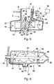
- Fig. 5
- den Aufbau einer Axial/Radialpumpe mit einem Differenzdrucksensor sowie
- Fig. 6
- den Aufbau einer Axialpumpe mit einem Differenzdrucksensor.
- Fig. 1
- a patient body in a schematic representation with the representation of a heart and a heart pump,
- Fig. 2
- a schematic representation of a heart as a cavity with a connected to this heart pump with sensors,
- Fig. 3
- schematically the representation of a heart with two sensors, which are connected to a device,
- Fig. 4
- the schematic representation of a heart with two possible arrangements of devices, each having sensors for pressure measurement,
- Fig. 5
- the structure of an axial / radial pump with a differential pressure sensor and
- Fig. 6
- the structure of an axial pump with a differential pressure sensor.
Die Herzpumpe 3 weist einen Rotor auf, der um die Achse 4 drehbar ist und dabei Blut in einen Katheter 5 fördert. Die Pumpe 3 saugt dabei durch einen Ansaugstutzen 6, der eine Wand des Herzens 2 durchsetzt, Blut aus dem Inneren des Herzens, beispielsweise aus einem Atrium oder einem Ventrikel, an und fördert dieses über die Kanüle / den Katheter 5 in ein Blutgefäß.The
Es ist zudem ein Steuergerät 7 dargestellt, das die Pumpe 3, beispielsweise mittels elektrischer Signale, ansteuert. Die Pumpe 3 wird durch einen Elektromotor mit Wicklungen und Magneten angetrieben. Dabei kann es sich bei dem Motor um einen bürstenlosen, beispielsweise im Pulsweitenmodulationsverfahren angesteuerten Elektromotor handeln.It is also shown a
Der Rotor der Pumpe 3 kann als Radialrotor ausgebildet sein, der axial einströmendes Fluid in radialer Richtung beschleunigt. In einem radial außen liegenden Sammelraum wird dann das geförderte Fluid/Blut gesammelt und durch den erzeugten Druck radial außen in die Kanüle 5 geleitet.The rotor of the
Zur Steuerung der Pumpe 3 mittels des Steuergeräts 7 ist die Berücksichtigung der Druckverhältnisse im Herzen 2 im Vergleich zu dem im Thorax 8 außerhalb des Herzens herrschenden Druck wichtig. Der Differenzdruck zwischen dem Raum innerhalb des Herzens 2 und dem Thorax 8 wird durch eine Sensoreinrichtung gemessen, auf die weiter unten noch genauer eingegangen wird.To control the
Die drei Sensoren 13, 14, 15 sind jeweils mit Funkeinrichtungen oder Induktionsspulen ausgestattet, die ihnen erlauben, erfasste Messwerte an eine Einrichtung 16 zur Bestimmung der Druckdifferenz zu senden. Die Einrichtung 16 kann beispielsweise als Mikrocontroller ausgebildet sein und mit einem Empfänger zum Empfangen der gemessenen Daten ausgestattet sein. Ein Computerprogramm, das auf dem Mikrocontroller läuft, ermittelt die Druckdifferenz, die durch die verschiedenen Sensoren 13, 14, 15 der Sensoreinrichtung erfasst wird. Diese kann dann an eine Steuereinrichtung der Pumpe 3' weitergeleitet werden. Die Sensoren 13, 14, 15 sind unmittelbar an der Herzpumpe 3' bzw. am Ansaugstutzen 11 der Pumpe angeordnet und befestigt. Sie können dabei, wie beispielsweise der Sensor 15, an der Außenseite des Pumpengehäuses befestigt sein, jedoch auch, wie der Sensor 14, im Inneren des Pumpenraums auf der Innenseite des Gehäuses.The three
In
In
In
Der Pumpenmotor weist einen innenliegenden Stator 40 auf, auf dem der Rotor 41 hydrostatisch und/oder magnetisch sowie in Radial- als auch in Axialrichtung gelagert sein kann. Der Pumpenmotor kann als bürstenloser Elektromotor ausgebildet sein. Im Rotor sind Fließkanäle für das Blut integriert, die dieses in axialer Richtung einfließen lassen und durch Zentrifugalwirkung in radialer Richtung ausstoßen. Um den Rotor 41 herum ist ein ringförmiger Sammelraum 42 in dem Gehäuse 37 gebildet, in dem das Blut sich sammelt und in Umfangsrichtung bis zu einer Ausströmöffnung 43 fließt, von wo es in eine Ausströmkanüle weiterbewegt wird.The pump motor has an
Es sind anhand der Pumpe der
Die zweite Differenzdruckeinrichtung, die alternativ an einer solchen Pumpe denkbar ist, weist einen Differenzdrucksensor 49 mit einer Membran 50 sowie eine Auswerteeinrichtung 51 auf. Der Sensor 49 ist auf einer Seite der Membran 50 über einen Kanal 52 mit dem Herzinneren verbunden, der im oder am Gehäuse 37 parallel zu dem Ansaugkanal 6' verläuft. Der Kanal 52 kann durch ein außen auf das Gehäuse 37 aufgesetztes gebogenes Rohr oder durch eine Bohrung in der Wand des Gehäuses 37 oder auch durch ein an der Innenwand des Gehäuses 37 verlaufendes Rohr gebildet sein.The second differential pressure device, which is alternatively conceivable on such a pump, has a
Der Sensor 49 kommuniziert auf der anderen Seite der Membran über eine Kanüle 53 mit der äußeren Umgebung des Pumpengehäuses 37 im Thorax. Die Differenzdruckermittlungseinrichtung 51 kommuniziert mit einem Aggregat 54.The
In
Mit der Einströmöffnung 63 ist ein Kanal 64 verbunden, der außen an der Wand des Gehäuses 56 verläuft und zu einem ersten Teilraum 65 auf einer Seite der Membran 66 eines Differenzdrucksensors 67 führt. Der zweite Teilraum 68 des Differenzdrucksensors 67 ist über eine Öffnung und/oder einen Fluidkanal mit der äußeren Umgebung des Pumpengehäuses 56 verbunden. Der Fluidkanal 64 kann auch innerhalb der Gehäusewand des Gehäuses 56 oder an der Innenseite der Gehäusewand des Gehäuses 56 zwischen der Einströmöffnung 63 und dem Differenzdrucksensor 67 verlaufen.With the
Durch die beschriebenen Lösungen ist in einfacher Weise die Bestimmung des Differenzdrucks zwischen dem absoluten Druck im Herzen des Patienten und dem Thorax möglich, wobei durch die Integration der Sensoreinrichtung wenigstens teilweise in ein implantierbares Aggregat sowohl die Herstellung als auch die Implantierung erleichtert wird.By the described solutions is in a simple way the determination of the differential pressure between the absolute pressure in the heart of the patient and the thorax possible, whereby the integration of the sensor device at least partially facilitates the production as well as the implantation in an implantable unit.
Mit der beschriebenen Sensoreinrichtung kann der wirkliche Füllungsdruck des Herzens ohne mögliche Einflüsse von Atmung, "Pressen" oder pathologischen Veränderungen des Thoraxdrucks ermittelt werden. Daher kann mit der gleichen Anzahl von Drucksensoren wie bisher ein vorteilhafteres Signal gemessen werden. Das ermöglicht eine schnellere Regelung von Herzpumpen als bisher, die robuster gegen diese Störeinflüsse ist. Dies würde zu einer konsequenten Ansaugprävention und durch die schnellere Adaption auf körperliche Belastung zu einer verbesserten Lebensqualität der Patienten führen. Auch eine Detektion einer pathologischen Veränderung im Thoraxdruck (z.B. Perikarderguss, Herzbeuteltamponade) wäre denkbar.With the described sensor device, the actual filling pressure of the heart can be determined without possible influences of respiration, "pressing" or pathological changes of the thorax pressure. Therefore, with the same number of pressure sensors as before, a more advantageous signal can be measured. This allows a faster control of heart pumps than before, which is more robust against these disturbances. This would lead to a consequent intake prevention and by the faster adaptation to physical stress to an improved quality of life of the patients. Detection of a pathological change in thoracic pressure (e.g., pericardial effusion, cardiac tamponade) would also be conceivable.
Claims (15)
Translated fromGermanPriority Applications (5)
| Application Number | Priority Date | Filing Date | Title |
|---|---|---|---|
| EP15173069.4AEP3108809A1 (en) | 2015-06-22 | 2015-06-22 | Method and device for measuring pressure on a patient's heart |
| CN201680036413.2ACN107771054A (en) | 2015-06-22 | 2016-06-16 | Apparatus and method for measuring the pressure in patient's heart |
| US15/738,486US20180168469A1 (en) | 2015-06-22 | 2016-06-16 | Device and method for measuring pressure in a patient's heart |
| DE112016002790.7TDE112016002790A5 (en) | 2015-06-22 | 2016-06-16 | Device and method for measuring pressure in the heart of a patient |
| PCT/EP2016/063960WO2016207066A1 (en) | 2015-06-22 | 2016-06-16 | Device and method for measuring pressure in a patient's heart |
Applications Claiming Priority (1)
| Application Number | Priority Date | Filing Date | Title |
|---|---|---|---|
| EP15173069.4AEP3108809A1 (en) | 2015-06-22 | 2015-06-22 | Method and device for measuring pressure on a patient's heart |
Publications (1)
| Publication Number | Publication Date |
|---|---|
| EP3108809A1true EP3108809A1 (en) | 2016-12-28 |
Family
ID=53488189
Family Applications (1)
| Application Number | Title | Priority Date | Filing Date |
|---|---|---|---|
| EP15173069.4AWithdrawnEP3108809A1 (en) | 2015-06-22 | 2015-06-22 | Method and device for measuring pressure on a patient's heart |
Country Status (5)
| Country | Link |
|---|---|
| US (1) | US20180168469A1 (en) |
| EP (1) | EP3108809A1 (en) |
| CN (1) | CN107771054A (en) |
| DE (1) | DE112016002790A5 (en) |
| WO (1) | WO2016207066A1 (en) |
Cited By (1)
| Publication number | Priority date | Publication date | Assignee | Title |
|---|---|---|---|---|
| EP3656411A1 (en) | 2018-11-26 | 2020-05-27 | Berlin Heart GmbH | Blood pump for supporting a cardiac function and method for producing a pump housing of a blood pump |
Families Citing this family (15)
| Publication number | Priority date | Publication date | Assignee | Title |
|---|---|---|---|---|
| CA3066361A1 (en) | 2017-06-07 | 2018-12-13 | Shifamed Holdings, Llc | Intravascular fluid movement devices, systems, and methods of use |
| WO2019094963A1 (en) | 2017-11-13 | 2019-05-16 | Shifamed Holdings, Llc | Intravascular fluid movement devices, systems, and methods of use |
| CN112004563B (en) | 2018-02-01 | 2024-08-06 | 施菲姆德控股有限责任公司 | Intravascular blood pump and methods of use and manufacture |
| US10960118B2 (en) | 2018-07-31 | 2021-03-30 | Abiomed, Inc. | Systems and methods for controlling a heart pump to minimize myocardial oxygen consumption |
| US12161857B2 (en) | 2018-07-31 | 2024-12-10 | Shifamed Holdings, Llc | Intravascular blood pumps and methods of use |
| WO2020073047A1 (en) | 2018-10-05 | 2020-04-09 | Shifamed Holdings, Llc | Intravascular blood pumps and methods of use |
| WO2021011473A1 (en) | 2019-07-12 | 2021-01-21 | Shifamed Holdings, Llc | Intravascular blood pumps and methods of manufacture and use |
| US11654275B2 (en) | 2019-07-22 | 2023-05-23 | Shifamed Holdings, Llc | Intravascular blood pumps with struts and methods of use and manufacture |
| EP4501393A3 (en) | 2019-09-25 | 2025-04-09 | Shifamed Holdings, LLC | Catheter blood pumps and collapsible pump housings |
| WO2021062265A1 (en) | 2019-09-25 | 2021-04-01 | Shifamed Holdings, Llc | Intravascular blood pump systems and methods of use and control thereof |
| US12121713B2 (en) | 2019-09-25 | 2024-10-22 | Shifamed Holdings, Llc | Catheter blood pumps and collapsible blood conduits |
| EP4072650A4 (en) | 2019-12-11 | 2024-01-10 | Shifamed Holdings, LLC | Descending aorta and vena cava blood pumps |
| CN114504728A (en)* | 2020-11-17 | 2022-05-17 | 苏州恒瑞宏远医疗科技有限公司 | A sensor for cardiac blood pump and cardiac blood pump |
| CN117982258B (en)* | 2022-10-27 | 2025-07-25 | 合源医疗器械(上海)有限公司 | Medical device |
| WO2025175188A1 (en)* | 2024-02-16 | 2025-08-21 | Shifamed Holdings, Llc | Implantable medical devices with hermetic canisters enclosed within a slip membrane |
Citations (8)
| Publication number | Priority date | Publication date | Assignee | Title |
|---|---|---|---|---|
| EP0902708A1 (en)* | 1996-04-30 | 1999-03-24 | Medtronic, Inc. | Method and apparatus for optimizing pacemaker av delay |
| US6328699B1 (en) | 2000-01-11 | 2001-12-11 | Cedars-Sinai Medical Center | Permanently implantable system and method for detecting, diagnosing and treating congestive heart failure |
| US20020120200A1 (en)* | 1997-10-14 | 2002-08-29 | Brian Brockway | Devices, systems and methods for endocardial pressure measurement |
| US20070249950A1 (en)* | 2006-04-20 | 2007-10-25 | Thomas Piaget | Implanted air passage sensors |
| US20070282210A1 (en) | 2006-05-04 | 2007-12-06 | Stern David R | Implantable wireless sensor for in vivo pressure measurement and continuous output determination |
| EP2415396A1 (en)* | 2010-08-06 | 2012-02-08 | BIOTRONIK SE & Co. KG | Heart monitor |
| WO2013122459A1 (en) | 2012-02-13 | 2013-08-22 | Rienks, Rienk | Method and system for detecting cardiac tamponade in a patient |
| EP1415672B1 (en) | 1999-04-20 | 2014-09-10 | Berlin Heart GmbH | Pump with pressure sensor |
Family Cites Families (12)
| Publication number | Priority date | Publication date | Assignee | Title |
|---|---|---|---|---|
| US5964694A (en)* | 1997-04-02 | 1999-10-12 | Guidant Corporation | Method and apparatus for cardiac blood flow assistance |
| DE10016422B4 (en)* | 2000-04-01 | 2013-10-31 | Impella Cardiosystems Ag | Paracardiac blood pump |
| US20080097226A1 (en)* | 2005-06-09 | 2008-04-24 | Mcconnell Patrick I | Evaluation of cardiac function using left ventricular pressure during LVAD support |
| US20070021680A1 (en)* | 2005-07-22 | 2007-01-25 | Transoma Medical, Inc. | Methods to reduce power to measure pressure |
| US7682313B2 (en)* | 2005-11-23 | 2010-03-23 | Vital Sensors Holding Company, Inc. | Implantable pressure monitor |
| US20080139951A1 (en)* | 2006-12-08 | 2008-06-12 | Cardiac Pacemakers, Inc. | Detection of Stenosis |
| US8027724B2 (en)* | 2007-08-03 | 2011-09-27 | Cardiac Pacemakers, Inc. | Hypertension diagnosis and therapy using pressure sensor |
| US20100081892A1 (en)* | 2008-09-30 | 2010-04-01 | NelIcor Puritan Bennett Ireland | Systems and Methods for Combined Pulse Oximetry and Blood Pressure Measurement |
| CN101983732B (en)* | 2010-11-19 | 2012-07-25 | 北京工业大学 | Blood pump control device based on physiological parameters |
| EP2520317B1 (en)* | 2011-05-05 | 2014-07-09 | Berlin Heart GmbH | Blood pump |
| GB201112350D0 (en)* | 2011-07-18 | 2011-08-31 | Calon Cardio Technology Ltd | Cardiac Pump |
| DE102013012391A1 (en)* | 2012-09-26 | 2014-03-27 | CircuLite GmbH | Pump, system with a blood pump and method of making a blood pump |
- 2015
- 2015-06-22EPEP15173069.4Apatent/EP3108809A1/ennot_activeWithdrawn
- 2016
- 2016-06-16DEDE112016002790.7Tpatent/DE112016002790A5/enactivePending
- 2016-06-16CNCN201680036413.2Apatent/CN107771054A/enactivePending
- 2016-06-16WOPCT/EP2016/063960patent/WO2016207066A1/ennot_activeCeased
- 2016-06-16USUS15/738,486patent/US20180168469A1/ennot_activeAbandoned
Patent Citations (8)
| Publication number | Priority date | Publication date | Assignee | Title |
|---|---|---|---|---|
| EP0902708A1 (en)* | 1996-04-30 | 1999-03-24 | Medtronic, Inc. | Method and apparatus for optimizing pacemaker av delay |
| US20020120200A1 (en)* | 1997-10-14 | 2002-08-29 | Brian Brockway | Devices, systems and methods for endocardial pressure measurement |
| EP1415672B1 (en) | 1999-04-20 | 2014-09-10 | Berlin Heart GmbH | Pump with pressure sensor |
| US6328699B1 (en) | 2000-01-11 | 2001-12-11 | Cedars-Sinai Medical Center | Permanently implantable system and method for detecting, diagnosing and treating congestive heart failure |
| US20070249950A1 (en)* | 2006-04-20 | 2007-10-25 | Thomas Piaget | Implanted air passage sensors |
| US20070282210A1 (en) | 2006-05-04 | 2007-12-06 | Stern David R | Implantable wireless sensor for in vivo pressure measurement and continuous output determination |
| EP2415396A1 (en)* | 2010-08-06 | 2012-02-08 | BIOTRONIK SE & Co. KG | Heart monitor |
| WO2013122459A1 (en) | 2012-02-13 | 2013-08-22 | Rienks, Rienk | Method and system for detecting cardiac tamponade in a patient |
Cited By (3)
| Publication number | Priority date | Publication date | Assignee | Title |
|---|---|---|---|---|
| EP3656411A1 (en) | 2018-11-26 | 2020-05-27 | Berlin Heart GmbH | Blood pump for supporting a cardiac function and method for producing a pump housing of a blood pump |
| WO2020109216A1 (en) | 2018-11-26 | 2020-06-04 | Berlin Heart Gmbh | Blood pump for supporting a cardiac function, and method for producing a pump housing of a blood pump |
| US12420081B2 (en) | 2018-11-26 | 2025-09-23 | Berlin Heart Gmbh | Blood pump for supporting heart function and method for producing a pump housing of a blood pump |
Also Published As
| Publication number | Publication date |
|---|---|
| DE112016002790A5 (en) | 2018-03-01 |
| WO2016207066A1 (en) | 2016-12-29 |
| CN107771054A (en) | 2018-03-06 |
| US20180168469A1 (en) | 2018-06-21 |
Similar Documents
| Publication | Publication Date | Title |
|---|---|---|
| EP3108809A1 (en) | Method and device for measuring pressure on a patient's heart | |
| EP3060805B1 (en) | Method for operating a supply device that supplies a channel with liquid, supply device, hollow catheter and catheter pump | |
| DE3316101C1 (en) | Redundant piston pump for operating single or multi-chamber pneumatic blood pumps | |
| DE69101106T2 (en) | Method and device for regulating the flow of a heart prosthesis with periodic flow. | |
| EP3263148B1 (en) | Method for determining the operating parameters of a blood pump | |
| EP0925080A1 (en) | Intracardiac blood pump | |
| WO2016173896A1 (en) | Pump device and methods for operating a pump for liquids | |
| EP1749549B1 (en) | System for drainage of cerebrospinal fluid | |
| EP3106187A1 (en) | Implantable heart pump | |
| WO2017032751A1 (en) | Heart pump and method for operating a heart pump | |
| EP3019211B1 (en) | Blood treatment device | |
| EP3060808B1 (en) | Method for monitoring an impeller pump used in a medical application | |
| WO2019234167A1 (en) | Determination appliance and method for determining a viscosity of a fluid | |
| DE202015009422U1 (en) | Implantable heart pump | |
| WO2017102164A1 (en) | Blood pump for supporting the heart, and method for operating the blood pump | |
| WO2019034670A1 (en) | PUMP WITH A ROTOR SENSOR FOR DETECTING PHYSIOLOGICAL PARAMETERS, FLOW AND MOTION PARAMETERS | |
| DE102013012391A1 (en) | Pump, system with a blood pump and method of making a blood pump | |
| EP2835141A1 (en) | Control of a blood pump | |
| WO2016001284A2 (en) | Method and heart support system for determining an outlet pressure | |
| WO2016146748A1 (en) | Heart pump device and method for operating same | |
| DE202008016450U1 (en) | Breast pump for pumping milk from a breast | |
| WO2011124388A1 (en) | Extraction system for extracting a body fluid | |
| DE102015222199A1 (en) | Cardiac assist pump, method of operating a cardiac assist pump and controller | |
| WO2011131766A1 (en) | Heart assistance device | |
| DE112022004359T5 (en) | System and method for providing ventricular support during extracorporeal membrane oxygenation |
Legal Events
| Date | Code | Title | Description |
|---|---|---|---|
| PUAI | Public reference made under article 153(3) epc to a published international application that has entered the european phase | Free format text:ORIGINAL CODE: 0009012 | |
| AK | Designated contracting states | Kind code of ref document:A1 Designated state(s):AL AT BE BG CH CY CZ DE DK EE ES FI FR GB GR HR HU IE IS IT LI LT LU LV MC MK MT NL NO PL PT RO RS SE SI SK SM TR | |
| AX | Request for extension of the european patent | Extension state:BA ME | |
| RIN1 | Information on inventor provided before grant (corrected) | Inventor name:GRANEGGER, MARCUS | |
| STAA | Information on the status of an ep patent application or granted ep patent | Free format text:STATUS: THE APPLICATION IS DEEMED TO BE WITHDRAWN | |
| 18D | Application deemed to be withdrawn | Effective date:20170629 |