EP3107834B1 - Capsule with a preferably rotationally symmetrical capsule body - Google Patents
Capsule with a preferably rotationally symmetrical capsule bodyDownload PDFInfo
- Publication number
- EP3107834B1 EP3107834B1EP15706402.3AEP15706402AEP3107834B1EP 3107834 B1EP3107834 B1EP 3107834B1EP 15706402 AEP15706402 AEP 15706402AEP 3107834 B1EP3107834 B1EP 3107834B1
- Authority
- EP
- European Patent Office
- Prior art keywords
- capsule
- outlet tube
- filter
- outlet pipe
- filter element
- Prior art date
- Legal status (The legal status is an assumption and is not a legal conclusion. Google has not performed a legal analysis and makes no representation as to the accuracy of the status listed.)
- Active
Links
Images


Classifications
- A—HUMAN NECESSITIES
- A47—FURNITURE; DOMESTIC ARTICLES OR APPLIANCES; COFFEE MILLS; SPICE MILLS; SUCTION CLEANERS IN GENERAL
- A47J—KITCHEN EQUIPMENT; COFFEE MILLS; SPICE MILLS; APPARATUS FOR MAKING BEVERAGES
- A47J31/00—Apparatus for making beverages
- A47J31/24—Coffee-making apparatus in which hot water is passed through the filter under pressure, i.e. in which the coffee grounds are extracted under pressure
- A47J31/34—Coffee-making apparatus in which hot water is passed through the filter under pressure, i.e. in which the coffee grounds are extracted under pressure with hot water under liquid pressure
- A47J31/36—Coffee-making apparatus in which hot water is passed through the filter under pressure, i.e. in which the coffee grounds are extracted under pressure with hot water under liquid pressure with mechanical pressure-producing means
- A47J31/3666—Coffee-making apparatus in which hot water is passed through the filter under pressure, i.e. in which the coffee grounds are extracted under pressure with hot water under liquid pressure with mechanical pressure-producing means whereby the loading of the brewing chamber with the brewing material is performed by the user
- A47J31/3676—Cartridges being employed
- A47J31/369—Impermeable cartridges being employed
- A47J31/3695—Cartridge perforating means for creating the hot water inlet
- B—PERFORMING OPERATIONS; TRANSPORTING
- B65—CONVEYING; PACKING; STORING; HANDLING THIN OR FILAMENTARY MATERIAL
- B65D—CONTAINERS FOR STORAGE OR TRANSPORT OF ARTICLES OR MATERIALS, e.g. BAGS, BARRELS, BOTTLES, BOXES, CANS, CARTONS, CRATES, DRUMS, JARS, TANKS, HOPPERS, FORWARDING CONTAINERS; ACCESSORIES, CLOSURES, OR FITTINGS THEREFOR; PACKAGING ELEMENTS; PACKAGES
- B65D85/00—Containers, packaging elements or packages, specially adapted for particular articles or materials
- B65D85/70—Containers, packaging elements or packages, specially adapted for particular articles or materials for materials not otherwise provided for
- B65D85/804—Disposable containers or packages with contents which are mixed, infused or dissolved in situ, i.e. without having been previously removed from the package
- B65D85/8043—Packages adapted to allow liquid to pass through the contents
- B65D85/8061—Filters
- B—PERFORMING OPERATIONS; TRANSPORTING
- B65—CONVEYING; PACKING; STORING; HANDLING THIN OR FILAMENTARY MATERIAL
- B65D—CONTAINERS FOR STORAGE OR TRANSPORT OF ARTICLES OR MATERIALS, e.g. BAGS, BARRELS, BOTTLES, BOXES, CANS, CARTONS, CRATES, DRUMS, JARS, TANKS, HOPPERS, FORWARDING CONTAINERS; ACCESSORIES, CLOSURES, OR FITTINGS THEREFOR; PACKAGING ELEMENTS; PACKAGES
- B65D85/00—Containers, packaging elements or packages, specially adapted for particular articles or materials
- B65D85/70—Containers, packaging elements or packages, specially adapted for particular articles or materials for materials not otherwise provided for
- B65D85/804—Disposable containers or packages with contents which are mixed, infused or dissolved in situ, i.e. without having been previously removed from the package
- B65D85/8043—Packages adapted to allow liquid to pass through the contents
- B65D85/8049—Details of the inlet
- B—PERFORMING OPERATIONS; TRANSPORTING
- B65—CONVEYING; PACKING; STORING; HANDLING THIN OR FILAMENTARY MATERIAL
- B65D—CONTAINERS FOR STORAGE OR TRANSPORT OF ARTICLES OR MATERIALS, e.g. BAGS, BARRELS, BOTTLES, BOXES, CANS, CARTONS, CRATES, DRUMS, JARS, TANKS, HOPPERS, FORWARDING CONTAINERS; ACCESSORIES, CLOSURES, OR FITTINGS THEREFOR; PACKAGING ELEMENTS; PACKAGES
- B65D85/00—Containers, packaging elements or packages, specially adapted for particular articles or materials
- B65D85/70—Containers, packaging elements or packages, specially adapted for particular articles or materials for materials not otherwise provided for
- B65D85/804—Disposable containers or packages with contents which are mixed, infused or dissolved in situ, i.e. without having been previously removed from the package
- B65D85/8043—Packages adapted to allow liquid to pass through the contents
- B65D85/8052—Details of the outlet
Definitions
- the present inventionrelates to a capsule with a preferably rotationally symmetrical capsule body according to the preamble of claim 1.
- Such capsulesare widely used today, in particular for the preparation of coffee or mixed coffee drinks.
- the capsuleforms a portion pack for the transport and storage of the substance and at the same time the design of the capsule plays an important role in the preparation of the beverage in a corresponding beverage preparation machine.
- Such machinesusually work with a high operating pressure, with the shape of the capsule having a strong influence on the flow behavior and the extraction process as a whole.
- the outlet pipe with its outlet openingis used to direct the finished drink directly into a cup placed underneath, without the need for sealed connections on the outlet side.
- Such a capsuleis, for example, by the WO 2009/115475 known.
- the outlet pipecan also only be a relatively short pipe socket which protrudes at least partially beyond the base of the capsule.
- the U.S. 2010/0062127 A1describes a cup closed with a lid for the preparation of a liquid foodstuff, the lid forming an entry side for a liquid. Disposed within the beaker is a static mixer formed of concentric tubes extending from the bottom of the beaker to the top.
- the WO 2012/117383 A1describes a capsule for receiving coffee powder for the preparation of a coffee infusion.
- the Capsulehas a central chimney and the coffee powder is placed in the surrounding chamber between the chimney and the side wall of the capsule.
- the capsulehas vertical filtering means, the brewing liquid introduced into the capsule converging against the filtering means from the outside towards the centre.
- the EP 2 537 779 A1describes a capsule according to the preamble of claim 1 for the preparation of a beverage with a central spout.
- the bottom of the capsuleis closed and is pierced by a penetration element in the outlet pipe.
- a problem with known capsulesis what is known as dripping, with liquid continuing to drip out of the outlet pipe immediately after the end of the preparation process or, in particular, when the used capsule is removed from the machine. Since there is no screening device for the escaping liquid on the machine side, a filter must also be installed in conventional capsules, which completely closes the bottom of the capsule over the outlet opening. However, this involves a great deal of effort and can also make the process of filling the capsule more difficult.
- optimal flow conditionsshould be created, with shear forces acting on the liquid flowing through the capsule. This achieves optimal mixing with air, which is advantageous for the formation of an optimal crema with coffee or milk foam formation with milk drinks.
- an even and homogeneous outlet jetshould be ensured.
- the outlet pipe extending into the interior of the capsuleforms an overflow for the liquid in the capsule, which prevents the residual liquid remaining in the chamber from being able to completely drain out.
- the filter element for retaining solids in the capsule before the liquid exits through the outlet openingis assigned directly to the outlet pipe, so that the fillable volume of the chamber does not have to be reduced by comprehensive filters.
- the filter openings of the filter elementhave a certain nozzle function and, depending on the design, a certain flow behavior can be brought about with these filter openings. Depending on the application, the filter openings are therefore nozzle openings.
- the cross-sectional shape of the at least one nozzle openingcan be configured differently. This can involve slots, cross slots, circular openings, and the cross-sectional shape can also be designed individually.
- the filter elementis arranged at the upper end of the outlet pipe facing the cover.
- the outlet pipecan extend to the underside of the lid and be connected to it.
- the lid of the capsulealso forms the upper end of the outlet pipe.
- the filter elementcan have filter openings in the form of slots or other openings in the outlet pipe, which preferably extend in the longitudinal direction of the outlet pipe and around the outlet pipe.
- a perforated screen structureis also conceivable, which preferably extends over the entire circumference of the outlet pipe.
- the filter elementis evidently integrated into the outlet pipe. If the filter openings are arranged in particular in the form of circumferentially vertically aligned slots on the outlet pipe, this causes a concentric flow in the horizontal direction. This creates an intensive turbulence in the outlet pipe, which promotes foaming of the liquid.
- both filter openings running laterally around the outlet pipe and filter openings arranged on an end plateare combined with one another. With this, the flow rate can be increased and the turbulence effect can be improved.
- the outlet pipeextends under the cover except for a remaining intermediate space and that the filter element is arranged above the inlet opening of the outlet pipe.
- the filter elementforms the upper end of the outlet pipe.
- the filter elementis a filter film that is stretched over the inlet opening.
- the filter elementis designed in one piece with the outlet pipe. This can be implemented particularly easily if the capsule body is an injection molded part made from plastic material. Alternatively, it is also conceivable that the filter element is a separate part placed on the outlet pipe. Obviously, the separate formation of the filter element allows for the manufacture of more complex shapes and filter openings.
- the outlet pipeis designed as a separate component over at least part of its length. This also enables the production of more complex shapes from plastic material.
- the capsule bodyis produced in a deep-drawing process and the outlet pipe in an injection molding process. It obviously is it is not necessary for the outlet pipe, which is designed as a separate component, to extend over the entire length from the inlet opening to the outlet opening.
- the outlet pipecan also be integrated into the capsule base as a short pipe socket. It is particularly advantageous if the outlet pipe, which is designed as a separate component, is inserted or can be inserted at the bottom of the capsule. This can be a press connection or snap connection or else an adhesive bond or weld.
- the base of the capsulehas a preferably circular depression into which the outlet pipe, which is designed as a separate component, is or can be locked.
- the snap-in connectionensures easy assembly of the components.
- different outlet pipescan be snapped into the same capsule body.
- the depression in the floorcan also be used to accommodate a bursting membrane.
- the outlet pipewhich is designed as a separate component, can have very different configurations. It can have a sealing edge on the upper edge, on which it is firmly connected to the lid. In such a case the filter element is formed by filter openings arranged around the upper edge of the outlet pipe.
- the upper end of the outlet pipecan also be arranged at a distance from the cover and can be closed off with a perforated foil, which acts as a water-permeable volume limitation.
- the outlet pipewhich is designed as a separate component, is closed at its bottom with a filter plate and is filled exclusively or additionally with a substance.
- a particularly optimal turbulencecan be achieved if the outlet pipe opens into a pipe socket of any design, in which a baffle plate is arranged. This can be held in such a way that the liquid flow in the outlet pipe strikes the baffle plate approximately at a right angle and then flows off laterally over the edge of the baffle plate.
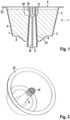
- a capsuleAs in figure 1 shown, a capsule, generally designated 1, consists of a capsule body 2 with a side wall 3 and a base 4.
- the capsule bodyhas an overall frustoconical configuration and is provided with a recess 23 on the base, which could also be omitted depending on the application.
- a peripheral edge 22At the upper end of the side wall 3 there is a peripheral edge 22 to which a cover 5 is fastened.
- the capsule body 2 together with the cover 5forms a closed chamber 6 which is filled with a substance 7, for example ground coffee.
- substance 7is shown in the exemplary embodiments below no longer shown.
- the capsule bodyis shown without the lid.
- the capsule according to figure 1is provided in its center with an outlet pipe 9 which tapers slightly and extends from the base 4 to the cover 5 and which opens out on the outside of the capsule body 2 in an outlet opening 8 .
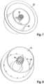
- the outlet pipe 9merges into a filter element 10, which has slit-like filter openings 11 ( figure 4 ) is provided.
- the actual inlet opening 13 in the outlet pipe 9, which is closed on all sides,is therefore located directly at the lower end of the filter openings.
- the end face of the extended outlet pipe 9 or of the filter element 10is sealed directly with the cover 5, which thus forms the upper end of the filter pipe.
- the outlet pipe 9is divided in its longitudinal direction by a star-shaped web 19 which extends from the inlet opening 13 to the outlet opening 8 .
- the inlet opening 13is arranged in a baffle plate 36 which is positioned in front of the star-shaped web 19 .
- the last section of the outlet pipeforms a pipe socket 24, from which the liquid can flow directly into a cup or into another vessel.
- the capsule body according to Figures 1 to 3is made in one piece as an injection molded part made of plastic. This also applies to the other exemplary embodiments with the exception of that according to FIG Figures 19 to 22 and 31 to 35 .
- the external configuration of the Capsule body and the dimensioning and arrangement of the outlet pipecould be modified in individual cases.
- the lid 5 of the capsuleforms an entry side for the passage of a liquid through the chamber 6, the lid 5 usually being pierced with the aid of a penetrant.
- the base 4forms an outlet side for the liquid with the outlet opening 8.
- the liquid entering on the inlet sidedoes not reach the outlet side directly, but must first pass through the filter element 10 and the outlet pipe 9.
- the filter openingscan have different shapes and configurations.
- the filter openingscan have different shapes and configurations.
- the inlet opening 13 in the baffle plate 36is also visible, which forms a flow orifice due to the slight narrowing of the cross section.
- the upper endis formed by the cover 5.
- FIGS. 6 to 8show an alternative exemplary embodiment of a capsule body 2, the filter element of which is constructed in the same way as in the exemplary embodiment according to FIG figure 1 .
- a partition tube 15is arranged, which is cylindrical and extends from the bottom 4 to the level of the peripheral edge 22 .
- an outer annular chamber 16 and an inner annular chamber 17are formed.
- transition openings 18 in the form of slotsare arranged in a region near the bottom.
- the coveris connected to the peripheral edge 22 , to the upper edge of the dividing wall tube 15 and to the end face of the filter element 10 .
- the transition openings 18could also exert a filter effect as required.
- a liquid injected into the outer chamber 16 on the inlet sidemust first pass through the transition openings 18 into the inner chamber 17 , rise there again up to the filter element 10 and then enter the outlet pipe 9 .
- the outlet pipe 9extends at the upper end only to an intermediate space 12 under the cover or under the peripheral edge 22, the dimension m being able to be adapted to the respective conditions.
- the filter element 10is arranged set back in the outlet pipe 9 relative to the inlet opening 13 .
- the filter elementis designed as a conical wall section with individual filter openings 11 ( figure 11 ) is formed, with the tip of the cone being directed towards the outlet opening 8 .
- a star-shaped web 19 in the outlet pipealso extends from the tip of the cone to the outlet opening.
- figure 12is the capsule body according to figure 9 supplemented by a partition tube 15, the function of which is otherwise the same as in the exemplary embodiment according to FIG figure 6 .
- the partition tube 15is reinforced by longitudinal ribs 25. This reinforcement allows the cylinder to be made more rigid, which is advantageous during production when the cover 5 is welded to the upper edge of the dividing wall tube.
- the partition tubeis provided with a circumferential rib 27 both in the area near the ground above the transition openings 18 and at the upper edge.
- a circumferential rib 27both in the area near the ground above the transition openings 18 and at the upper edge.
- the upper ribalso serves in particular as a sealing surface for attaching the cover film.
- the filter body 10also consists of a conical wall section with individual filter openings 11.
- the apex of the coneis directed upwards against the lid.
- the dividing wall tube 15is also provided with a sealing edge 26 on the inside.
- a bursting foil 20is fastened to this, which extends directly below the filter element 10 and is also connected to the upper end face of the outlet pipe 9 .
- the interior of the capsulein particular the outer chamber 16 and part of the inner chamber 17, is hermetically sealed from the atmosphere outside the capsule.
- the rupture foilruptures under the effect of the internal pressure in the capsule, so that the liquid can flow through the filter element 10 into the outlet pipe.
- a bursting foilcould also be fastened directly above the inlet opening 13 of the outlet pipe 9 in the exemplary embodiments described above.
- the hermetic seal using a bursting foilis useful for various reasons, for example if the capsule body and the lid are made of a material that has aroma-tight or gas-tight properties and that is difficult or impossible to penetrate for oxygen, or to allow moisture exchange between the capsule filling and the prevent environment.
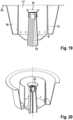
- the filter element 21consists of a separate component which is snapped onto the upper end of the outlet pipe 9 .
- the filter element 21is provided with an inlet funnel 28 which leads to a perforated screen plate 31 .
- a web 19is also arranged in the outlet pipe 9, from which figure 19 a bridge wing is completely cut.
- a slightly enlarged pipe socket 24is again shown as part of the outlet pipe with the outlet opening 8 .
- the web 19 arranged in the outlet piperuns in a star shape with individual wall sections which are arranged at an angle of 120° to one another.
- alternative web arrangementswould be conceivable, in particular, for example, a crossed web.
- a fine filter 14is arranged in each case in the direction of flow in front of the filter openings of the filter element.
- a bursting foil 20is attached over the inlet opening 13, which can be seen according to figure 24 after the filter element and according to figure 25 in front of the filter element.
- FIG 26shows purely schematically a capsule 1 according to one of the described embodiments in the holder 32 of a beverage preparation machine not shown in detail.
- This holder 32has an opening 33 on the underside, through which the pipe socket 24 of the outlet pipe 9 protrudes.
- the chamber-shaped holderis closed with a cover part 34 which has a penetration element in the form of an injection needle 35 .
- a liquidflows through this, for example hot water, under pressure, into the outer chamber 16 if a partition pipe 15 is present. Then through the transition openings 18 into the inner chamber 17 to the filter element 10 and through this into the outlet pipe 9.
- an extraction process of different substances or a mixture of extraction and solutiontakes place.
- the two chamberscould contain ground coffee and powdered milk, with the coffee being extracted and the powdered milk being dissolved with the liquid flowing through.
- the Figures 27 and 28show a capsule or a capsule body in which the outlet pipe is closed at the upper end with a closing plate 37.
- the filter element 10is arranged below this end plate, which is arranged at a distance from the cover 5 . This consists of longitudinal slots distributed over the circumference of the filter tube.
- the cross-shaped web 19extends to the end plate 37 and is connected to it, so that the outlet pipe 9 is divided into individual chambers. The liquid flowing in radially through the slits hits the webs, which results in very good turbulence.
- the capsulealso has a dividing wall tube 15 with peripheral transition openings 18, the dividing wall tube protruding beyond the end plate 37 and being welded to the cover 5 at the upper edge.
- a dividing wall tube 15 with peripheral transition openings 18, the dividing wall tube protruding beyond the end plate 37 and being welded to the cover 5 at the upper edgecould also be realized with alternative capsule bodies, in particular the dividing wall pipe could also be omitted.
- the partition tube 15is preferably arranged at a lower level than the peripheral edge 22.
- the embodiment according to figure 29shows a capsule body that is almost identical to that according to figure 28 .
- filter openingsare arranged in the end plate 37 in a perforated screen structure.
- the slotsit is also conceivable for the slots to be omitted and for one or more nozzle openings to be arranged only on the upper closing plate 37, which do not necessarily have to have a filter function.
- the section of the outlet pipe 9 located inside the capsulehas a significantly larger internal diameter than in the region of the section located outside the capsule.
- the covernot shown here, is welded to the peripheral edge 22 and to the upper edge of the outlet pipe, with the upper edge of the outlet pipe not having to lie at the level of the peripheral edge.
- the liquidenters the outlet pipe at the upper end through inlet slots 38 .
- the diameter of the outlet pipe 9 within the capsulecorresponds approximately to the diameter of the recess 23 in the base of the capsule.
- the filter element 10is arranged in the outlet area, specifically in the form of filter lamellae 39, which extend over the entire outside of the capsule Extend section of the outlet pipe.
- the filter element at this pointcould also consist of a screen plate with openings in a perforated screen structure.
- the filter elementit would be possible in principle for the filter element to be always arranged in the area of the outlet opening in the outlet pipe, even in an alternative embodiment of the capsule body.
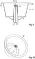
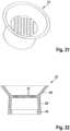
- the capsule body 2itself consists of an approximately frustoconical side wall 3 which has a peripheral edge 22 on the larger diameter for fixing the lid.
- a hollow-cylindrical depression 43is arranged on the bottom 4 and merges into a pipe socket 44 .
- a peripheral embossed edgeis attached as a latching means on the inside of the depression.
- a baffle plate 45is held on lateral ribs.
- radial stiffening ribs 46are arranged under the floor, which connect the pipe socket 44, the recess 43 and the floor 4 with each other.
- An outlet pipe insert 40is snapped into the depression 43 and has a snap-on edge 42 at its bottom.
- the floor itselfis closed off by a filter plate 41 .
- Slots 47are arranged as a further filter element at the upper edge.
- the upper edgeis closed here by the cover (5) ( figure 32 ).
- the diameter of the outlet pipe insert 40is larger than the diameter of the recess 43 and extends close to the outer diameter of the bottom 4.
- a bursting foilcan be arranged in the recess 43 so that the interior of the capsule is hermetically sealed.
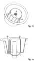
- Figure 33shows the same capsule body 2 as figure 31 , wherein only the sectional plane on the left half is laid through a stiffening rib 46.
- an alternative outlet pipe insert 48which has a significantly smaller pipe diameter, is snapped into the recess 43.
- This outlet pipe insertis designed in one piece with a snap-in pot 49 at the lower end. This bridges the difference in diameter and ensures sufficient lateral stability.
- a bursting membranecan be used at the bottom of the depression 43 .
- the only filter elementare the circumferential openings 50 at the top edge of the spout insert 48. The upper edge is also intended to be closed with the lid, analogously to Figure 32.
- outlet pipe insertsit is possible with the separate configuration of outlet pipe inserts to use completely different outlet pipes with different filters in the same capsule body.
- the capsule bodies and the outlet pipescan also be modified and combined as desired with this design. It would be conceivable, for example, not to cover the upper edge of the outlet pipe with the cover but with an end plate or with a filter film.
- the pipe socket 44could, for example, also with filter lamellae 39 analogous to figure 30 be provided.
- FIG figure 36shows a further embodiment of a capsule with a certain similarity to the embodiment according to FIG figure 32 .
- a separate outlet pipe insert 40is also snapped into place in a depression in the base of the capsule body. This is provided in one piece with a filter plate 41 .
- a bursting foil 20can be arranged between the filter plate and the outlet opening 8 .
- the upper end of the outlet pipe 40is not sealed with the cover 5 and there are also no lateral openings in the outlet pipe. Rather, an intermediate space 12 remains between the cover 5 and the upper end of the outlet pipe 40 and the latter is covered with a filter film 51 .
- analogous to the exemplary embodiment according to FIG figure 32included a substance which is separated from the outer annular chamber independently of the cover.
Landscapes
- Engineering & Computer Science (AREA)
- Mechanical Engineering (AREA)
- Food Science & Technology (AREA)
- Apparatus For Making Beverages (AREA)
- Medicinal Preparation (AREA)
- Manufacturing Of Micro-Capsules (AREA)
Description
Translated fromGermanDie vorliegende Erfindung betrifft eine Kapsel mit einem vorzugsweise rotationssymmetrisch ausgebildeten Kapselkörper gemäss dem Oberbegriff von Anspruch 1. Derartige Kapseln finden heute insbesondere für die Zubereitung von Kaffee oder Kaffeemischgetränken verbreitet Anwendung.The present invention relates to a capsule with a preferably rotationally symmetrical capsule body according to the preamble of
Die Kapsel bildet eine Portionsverpackung für den Transport und die Lagerung der Substanz und gleichzeitig spielt die Ausgestaltung der Kapsel eine wichtige Rolle bei der Zubereitung des Getränks in einer entsprechenden Getränkezubereitungsmaschine. Derartige Maschinen arbeiten in der Regel mit einem hohen Betriebsdruck, wobei die Form der Kapsel das Strömungsverhalten und den Extraktionsprozess insgesamt stark beeinflusst. Das Auslaufrohr mit seiner Auslauföffnung dient dazu, das fertige Getränk direkt in eine darunter aufgestellte Tasse zu lenken, ohne dass auf der Austrittseite dichtende Anschlüsse erforderlich sind. Eine derartige Kapsel ist beispielsweise durch die
Die
Die
Die
Ein Problem bei bekannten Kapseln besteht im sogenannten Nachtropfen, wobei unmittelbar nach Beendigung des Zubereitungsprozesses oder insbesondere auch bei der Entfernung der gebrauchten Kapsel aus der Maschine weiterhin Flüssigkeit aus dem Auslaufrohr tropft. Da maschinenseitig keinerlei Siebvorrichtung für die austretende Flüssigkeit vorgesehen ist, muss bei konventionellen Kapseln ausserdem ein Filter eingebaut werden, das den Boden der Kapsel über der Auslauföffnung flächendeckend abschliesst. Dies ist jedoch mit einem grossen Aufwand verbunden und kann zudem den Füllprozess der Kapsel erschweren.A problem with known capsules is what is known as dripping, with liquid continuing to drip out of the outlet pipe immediately after the end of the preparation process or, in particular, when the used capsule is removed from the machine. Since there is no screening device for the escaping liquid on the machine side, a filter must also be installed in conventional capsules, which completely closes the bottom of the capsule over the outlet opening. However, this involves a great deal of effort and can also make the process of filling the capsule more difficult.
Es ist daher eine Aufgabe der Erfindung, eine Kapsel der eingangs genannten Art zu schaffen, welche einfach und kostengünstig hergestellt werden kann und mit welcher das Filterproblem und gleichzeitig auch das Problem des Nachtropfens gelöst wird. Ausserdem sollen strömungstechnisch optimale Bedingungen geschaffen werden, wobei Scherkräfte auf die durch die Kapsel strömende Flüssigkeit einwirken. Damit wird eine optimale Durchmischung mit Luft erzielt, was für die Bildung einer optimalen Crema beim Kaffee oder einer Milchschaumbildung bei Milchgetränken vorteilhaft ist. Zugleich soll ein gleichmässiger und homogener Auslaufstrahl sichergestellt werden. Diese Aufgabe wird erfindungsgemäss mit einer Kapsel gelöst, welche die Merkmale im Anspruch 1 aufweist.It is therefore an object of the invention to create a capsule of the type mentioned at the outset, which can be produced simply and inexpensively and with which the filter problem and at the same time the problem of dripping are solved. In addition, optimal flow conditions should be created, with shear forces acting on the liquid flowing through the capsule. This achieves optimal mixing with air, which is advantageous for the formation of an optimal crema with coffee or milk foam formation with milk drinks. At the same time, an even and homogeneous outlet jet should be ensured. This task will solved according to the invention with a capsule which has the features in
Das sich in das Innere der Kapsel erstreckende Auslaufrohr bildet einen Überlauf für die Flüssigkeit in der Kapsel, welcher verhindert, dass die in der Kammer verbleibende Restflüssigkeit vollständig auslaufen kann. Das Filterelement zum Zurückhalten von Feststoffen in der Kapsel vor dem Austritt der Flüssigkeit durch die Auslauföffnung ist unmittelbar dem Auslaufrohr zugeordnet, so dass das füllbare Volumen der Kammer nicht durch flächendeckende Filter reduziert werden muss.The outlet pipe extending into the interior of the capsule forms an overflow for the liquid in the capsule, which prevents the residual liquid remaining in the chamber from being able to completely drain out. The filter element for retaining solids in the capsule before the liquid exits through the outlet opening is assigned directly to the outlet pipe, so that the fillable volume of the chamber does not have to be reduced by comprehensive filters.
Die Filteröffnungen des Filterelements haben eine gewisse Düsenfunktion und je nach Ausgestaltung kann mit diesen Filteröffnungen ein bestimmtes Strömungsverhalten bewirkt werden. Je nach Anwendungsfall sind die Filteröffnungen somit Düsenöffnungen. Die Querschnittsform der wenigstens einen Düsenöffnung kann unterschiedlich ausgestaltet werden. Es kann sich dabei um Schlitze, Kreuzschlitze, kreisförmige Öffnungen handeln, wobei auch die Querschnittsform individuell ausgestaltet werden kann.The filter openings of the filter element have a certain nozzle function and, depending on the design, a certain flow behavior can be brought about with these filter openings. Depending on the application, the filter openings are therefore nozzle openings. The cross-sectional shape of the at least one nozzle opening can be configured differently. This can involve slots, cross slots, circular openings, and the cross-sectional shape can also be designed individually.
Das Filterelement ist am oberen, dem Deckel zugewandten Ende des Auslaufrohrs angeordnet. Das Auslaufrohr kann sich dabei bis an die Unterseite des Deckels erstrecken und mit diesem verbunden sein. In einem derartigen Fall bildet der Deckel der Kapsel gleichzeitig den oberen Abschluss des Auslaufrohrs.The filter element is arranged at the upper end of the outlet pipe facing the cover. The outlet pipe can extend to the underside of the lid and be connected to it. In such a case, the lid of the capsule also forms the upper end of the outlet pipe.
Das Filterelement kann dabei Filteröffnungen in der Form von Schlitzen oder anderen Öffnungen im Auslaufrohr aufweisen, die sich vorzugsweise in Längsrichtung des Auslaufrohrs und um das Auslaufrohr erstrecken. Denkbar ist aber auch eine Lochsiebstruktur, die sich vorzugsweise über den gesamten Umfang des Auslaufohrs erstreckt. Bei dieser Anordnung ist das Filterelement ersichtlicherweise in das Auslaufrohr integriert. Wenn die Filteröffnungen insbesondere in der Form von umlaufend vertikal ausgerichteten Schlitzen am Auslaufrohr angeordnet sind, bewirkt dies eine konzentrische Strömung in horizontaler Richtung. Dadurch entsteht eine intensive Verwirbelung im Auslaufrohr, welche das Aufschäumen der Flüssigkeit begünstigt. Selbstverständlich ist es dabei auch denkbar, dass sowohl seitlich um das Auslaufrohr verlaufende Filteröffnungen, als auch auf einer Abschlussplatte angeordnete Filteröffnungen miteinander kombiniert sind. Damit kann die Durchflussrate erhöht und der Verwirbelungseffekt verbessert werden.The filter element can have filter openings in the form of slots or other openings in the outlet pipe, which preferably extend in the longitudinal direction of the outlet pipe and around the outlet pipe. However, a perforated screen structure is also conceivable, which preferably extends over the entire circumference of the outlet pipe. In this arrangement the filter element is evidently integrated into the outlet pipe. If the filter openings are arranged in particular in the form of circumferentially vertically aligned slots on the outlet pipe, this causes a concentric flow in the horizontal direction. This creates an intensive turbulence in the outlet pipe, which promotes foaming of the liquid. Of course, it is also conceivable that both filter openings running laterally around the outlet pipe and filter openings arranged on an end plate are combined with one another. With this, the flow rate can be increased and the turbulence effect can be improved.
Alternativ ist es auch denkbar, dass sich das Auslaufrohr bis auf einen verbleibenden Zwischenraum unter den Deckel erstreckt und dass das Filterelement über der Einlassöffnung des Auslaufrohrs angeordnet ist. Bei dieser Konstruktion bildet das Filterelement den oberen Abschluss des Auslaufrohrs. Das Filterelement ist dabei eine Filterfolie, welche über die Einlassöffnung gespannt wird.Alternatively, it is also conceivable that the outlet pipe extends under the cover except for a remaining intermediate space and that the filter element is arranged above the inlet opening of the outlet pipe. With this design, the filter element forms the upper end of the outlet pipe. The filter element is a filter film that is stretched over the inlet opening.
Eine besonders einfache Herstellung der Kapsel wird dadurch ermöglicht, dass das Filterelement einstückig mit dem Auslaufrohr ausgebildet ist. Dies lässt sich besonders einfach realisieren, wenn der Kapselkörper ein Spritzgussteil aus Kunststoffmaterial ist. Alternativ ist es aber auch denkbar, dass das Filterelement ein auf das Auslaufrohr aufgesetztes separates Teil ist. Die separate Ausbildung des Filterelements erlaubt ersichtlicherweise die Herstellung von komplexeren Formen und Filteröffnungen.A particularly simple production of the capsule is made possible by the fact that the filter element is designed in one piece with the outlet pipe. This can be implemented particularly easily if the capsule body is an injection molded part made from plastic material. Alternatively, it is also conceivable that the filter element is a separate part placed on the outlet pipe. Obviously, the separate formation of the filter element allows for the manufacture of more complex shapes and filter openings.
Erfindungsgemäss ist das Auslaufrohr wenigstens über einen Teil seiner Länge als separates Bauteil ausgebildet. Damit wird auch die Herstellung komplexerer Formen aus Kunststoffmaterial ermöglicht. Ausserdem ist es denkbar, dass beispielsweise der Kapselkörper in einem Tiefziehverfahren und das Auslaufrohr in einem Spritzgussverfahren hergestellt werden. Dabei ist es ersichtlicherweise nicht notwendig, dass sich das als separates Bauteil ausgebildete Auslaufrohr über die gesamte Länge von der Einlassöffnung bis zur Auslauföffnung erstreckt. Insbesondere im Bereich der Auslauföffnung kann das Auslaufrohr auch als kurzer Rohrstutzen in den Kapselboden integriert sein. Dabei ist es besonders vorteilhaft, wenn das als separates Bauteil ausgebildete Auslaufrohr am Boden der Kapsel eingesetzt oder einsetzbar ist. Es kann sich dabei um eine Pressverbindung oder Schnappverbindung oder auch um eine Verklebung oder Verschweissung handeln.According to the invention, the outlet pipe is designed as a separate component over at least part of its length. This also enables the production of more complex shapes from plastic material. In addition, it is conceivable that, for example, the capsule body is produced in a deep-drawing process and the outlet pipe in an injection molding process. It obviously is it is not necessary for the outlet pipe, which is designed as a separate component, to extend over the entire length from the inlet opening to the outlet opening. In particular in the area of the outlet opening, the outlet pipe can also be integrated into the capsule base as a short pipe socket. It is particularly advantageous if the outlet pipe, which is designed as a separate component, is inserted or can be inserted at the bottom of the capsule. This can be a press connection or snap connection or else an adhesive bond or weld.
Weitere Vorteile können erzielt werden, wenn der Boden der Kapsel eine vorzugsweise kreisförmige Vertiefung aufweist, in welche das als separates Bauteil ausgebildete Auslaufrohr eingerastet oder einrastbar ist. Die Rastverbindung gewährleistet ein einfaches Zusammensetzen der Bauteile. Ausserdem können in den gleichen Kapselkörper unterschiedliche Auslaufrohre eingerastet werden. Die Vertiefung im Boden kann zusätzlich zur Aufnahme einer Berstfolie dienen.Further advantages can be achieved if the base of the capsule has a preferably circular depression into which the outlet pipe, which is designed as a separate component, is or can be locked. The snap-in connection ensures easy assembly of the components. In addition, different outlet pipes can be snapped into the same capsule body. The depression in the floor can also be used to accommodate a bursting membrane.
Das als separates Bauteil ausgebildete Auslaufrohr kann ganz unterschiedliche Konfigurationen aufweisen. Es kann an der Oberkante einen Siegelrand aufweisen, an dem es fest mit dem Deckel verbunden ist. In einem derartigen Fall wird das Filterelement durch Filteröffnungen gebildet, welche um den oberen Rand des Auslaufrohrs angeordnet sind. Alternativ kann das obere Ende des Auslaufrohrs auch im Abstand zum Deckel angeordnet sein und mit einer Lochfolie abgeschlossen sein, welche als wasserdurchlässige Volumenbegrenzung wirkt. Erfindungsgemäss ist das als separates Bauteil ausgebildete Auslaufrohr an dessen Boden mit einer Filterplatte abgeschlossen und ist ausschliesslich oder zusätzlich mit einer Substanz gefüllt.The outlet pipe, which is designed as a separate component, can have very different configurations. It can have a sealing edge on the upper edge, on which it is firmly connected to the lid. In such a case the filter element is formed by filter openings arranged around the upper edge of the outlet pipe. Alternatively, the upper end of the outlet pipe can also be arranged at a distance from the cover and can be closed off with a perforated foil, which acts as a water-permeable volume limitation. According to the invention, the outlet pipe, which is designed as a separate component, is closed at its bottom with a filter plate and is filled exclusively or additionally with a substance.
Eine besonders optimale Verwirbelung kann erreicht werden, wenn das Auslaufrohr in einen beliebig ausgebildeten Rohrstutzen mündet, in dem eine Prallplatte angeordnet ist. Diese kann so gehalten sein, dass der Flüssigkeitsstrom im Auslaufrohr etwa im rechten Winkle auf die Prallplatte trifft und danach seitlich über den Rand der Prallplatte abfliesst.A particularly optimal turbulence can be achieved if the outlet pipe opens into a pipe socket of any design, in which a baffle plate is arranged. This can be held in such a way that the liquid flow in the outlet pipe strikes the baffle plate approximately at a right angle and then flows off laterally over the edge of the baffle plate.
Weitere Einzelmerkmale und Vorteile der Erfindung ergeben sich aus der nachstehenden Beschreibung von Ausführungsbeispielen und aus den Zeichnungen. Dabei sind die Ausführungsformen der
- Figur 1:
- Einen Querschnitt durch eine Kapsel mit einem bis zum Deckel geführten Auslaufrohr und integriertem Filterelement,
- Figur 2:
- Eine perspektivische Darstellung der Innenseite des Kapselkörpers gemäss
Figur 1 , - Figur 3:
- Eine perspektivische Darstellung der Aussenseite des Kapselkörpers gemäss
Figur 1 , - Figur 4:
- Eine vergrösserte Detaildarstellung des Filterelements an der Kapsel gemäss
Figur 1 mit schlitzförmigen Filteröffnungen, - Figur 5:
- Eine vergrösserte Detaildarstellung eines Filterelements mit Lochsiebstruktur,
- Figur 6:
- Ein Querschnitt durch ein alternatives Beispiel eines Kapselkörpers mit einem Trennwandrohr,
- Figur 7:
- Eine perspektivische Darstellung der Innenseite des Kapselkörpers gemäss
Figur 6 , - Figur 8:
- Eine perspektivische Darstellung des Trennwandrohrs am Filterkörper gemäss
Figur 7 , - Figur 9:
- Ein Querschnitt durch ein alternatives Ausführungsbeispiel eines Filterkörpers mit einem in das Ablaufrohr integrierten Filterelement,
- Figur 10:
- Eine perspektivische Darstellung der Innenseite des Kapselkörpers gemäss
Figur 9 , - Figur 11:
- Eine vergrösserte Detaildarstellung des Filterelements am
Kapselkörper gemäss Figur 10 , - Figur 12:
- Ein Querschnitt durch einen Kapselkörper analog zu
Figur 9 - Figur 13:
- Eine perspektivische Darstellung auf ein alternatives Ausführungsbeispiel eines Kapselkörpers mit Längsrippen am Trennwandrohr,
- Figur 14:
- Der teilweise aufgeschnittene Kapselkörper gemäss
Figur 13 , - Figur 15:
- Eine perspektivische und aufgeschnittene Darstellung eines weiteren Kapselkörpers mit einer Verstärkungsrippe in Umfangsrichtung am Trennwandrohr,
- Figur 16:
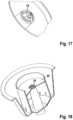
- Ein Querschnitt durch einen Kapselkörper mit Trennwandrohr und Berstfolie,
- Figur 17:
- Eine vergrösserte Detaildarstellung des Filterelements am
Kapselkörper gemäss Figur 16 , - Figur 18:
- Eine perspektivische und teilweise aufgeschnittene Darstellung des Kapselkörpers gemäss
Figur 16 , - Figur 19:
- Ein Querschnitt durch einen Kapselkörper mit einem Filterelement als separates Bauteil,
- Figur 20:
- Eine perspektivische und teilweise aufgeschnittene Darstellung des Kapselkörpers gemäss
Figur 19 , - Figur 21:
- Eine perspektivische und vergrösserte Darstellung des separaten Filterelements gemäss
Figur 19 , - Figur 22:
- Ein Querschnitt durch das separate Filterelement gemäss
Figur 21 , - Figur 23:
- Eine vergrösserte Detaildarstellung auf eine Auslauföffnung eines Auslaufrohrs mit eingebauten Stegen,
- Figur 24:
- Eine Detaildarstellung eines Filterelements mit Feinfilter und Berstfolie nach dem Filterelement,
- Figur 25:
- Eine Detaildarstellung eines Filterelements mit Feinfilter und Berstfolie vor dem Filterelement,
- Figur 26:
- Ein System bestehend aus einer Kapsel und einer Getränkezubereitungsmaschine in schematischer Darstellung,
Figur 27- Ein Querschnitt durch ein alternatives Ausführungsbeispiel einer Kapsel mit einem Trennwandrohr und mit schlitzartigen Filteröffnungen am oberen Ende des Auslaufrohrs,
Figur 28- Eine teilweise geschnittene perspektivische Darstellung des Kapselkörpers gemäss
Figur 27 , Figur 29- Eine perspektivische geschnittene Darstellung des Kapselkörpers gemäss
Figur 28 mit zusätzlichen Filteröffnungen, Figur 30- Eine teilweise geschnittene perspektivische Darstellung eines alternativen Kapselkörpers mit einem Filterelement im Bereich der Auslassöffnung,
Figur 31- Eine Seitenansicht eines erfindungsgemässen Ausführungsbeispiels eines Kapselkörpers mit eingerastetem Auslaufrohr,
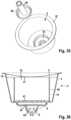
Figur 32- Ein Querschnitt durch den
Kapselkörper gemäss Figur 31 , Figur 33- Ein Querschnitt durch den
Kapselkörper gemäss Figur 31 , jedoch mit einem alternativen Auslaufrohr, Figur 34- Eine perspektivische Darstellung des Kapselkörpers gemäss
Figur 32 vor dem Einsetzen des Auslaufrohrs, Figur 35- Eine perspektivische Darstellung des Kapselkörpers gemäss
Figur 33 vor dem Einsetzen des Auslaufrohrs, und Figur 36- Einen Querschnitt durch eine weitere erfindungsgemässe Ausgestaltung eines Kapselkörpers.
- Figure 1:
- A cross section through a capsule with an outlet pipe leading to the lid and an integrated filter element,
- Figure 2:
- A perspective view of the inside of the capsule body according to FIG
figure 1 , - Figure 3:
- A perspective view of the outside of the capsule body according to FIG
figure 1 , - Figure 4:
- An enlarged detailed view of the filter element on the capsule according to
figure 1 with slit-shaped filter openings, - Figure 5:
- An enlarged detailed view of a filter element with a perforated screen structure,
- Figure 6:
- A cross section through an alternative example of a capsule body with a bulkhead tube,
- Figure 7:
- A perspective view of the inside of the capsule body according to FIG
figure 6 , - Figure 8:
- A perspective view of the partition tube on the filter body according to
figure 7 , - Figure 9:
- A cross section through an alternative embodiment of a filter body with a filter element integrated into the drain pipe,
- Figure 10:
- A perspective view of the inside of the capsule body according to FIG
figure 9 , - Figure 11:
- An enlarged detailed view of the filter element on the capsule body according to
figure 10 , - Figure 12:
- A cross section through a capsule body analogous to
figure 9 but with additional partition tube, - Figure 13:
- A perspective view of an alternative embodiment of a capsule body with longitudinal ribs on the partition tube,
- Figure 14:
- The partially cut open capsule body according to
figure 13 , - Figure 15:
- A perspective and cutaway view of another capsule body with a reinforcing rib in the circumferential direction on the partition tube,
- Figure 16:
- A cross-section through a capsule body with partition tube and rupture membrane,
- Figure 17:
- An enlarged detailed view of the filter element on the capsule body according to
figure 16 , - Figure 18:
- A perspective and partially cutaway representation of the capsule body according to FIG
figure 16 , - Figure 19:
- A cross section through a capsule body with a filter element as a separate component,
- Figure 20:
- A perspective and partially cutaway representation of the capsule body according to FIG
figure 19 , - Figure 21:
- A perspective and enlarged view of the separate filter element according to
figure 19 , - Figure 22:
- A cross section through the separate filter element according to
figure 21 , - Figure 23:
- An enlarged detailed view of an outlet opening of an outlet pipe with built-in bars,
- Figure 24:
- A detailed representation of a filter element with fine filter and bursting foil after the filter element,
- Figure 25:
- A detailed view of a filter element with fine filter and bursting foil in front of the filter element,
- Figure 26:
- A system consisting of a capsule and a beverage preparation machine in a schematic representation,
- figure 27
- A cross section through an alternative embodiment of a capsule with a dividing wall tube and with slit-like filter openings at the upper end of the outlet tube,
- figure 28
- A partially sectioned perspective view of the capsule body according to
figure 27 , - figure 29
- A perspective sectioned view of the capsule body according to
figure 28 with additional filter openings, - figure 30
- A partially sectioned perspective view of an alternative capsule body with a filter element in the area of the outlet opening,
- figure 31
- A side view of an embodiment of a capsule body according to the invention with an outlet pipe engaged,
- figure 32
- A cross section through the capsule body according to
figure 31 , - Figure 33
- A cross section through the capsule body according to
figure 31 , but with an alternative outlet pipe, - figure 34
- A perspective view of the capsule body according to
figure 32 before inserting the outlet pipe, - figure 35
- A perspective view of the capsule body according to
Figure 33 before inserting the outlet pipe, and - figure 36
- A cross section through a further embodiment of a capsule body according to the invention.
Wie in
Die Kapsel gemäss
Das Auslaufrohr 9 ist in seiner Längsrichtung durch einen sternförmigen Steg 19 unterteilt, der sich von der Einlassöffnung 13 bis zur Auslassöffnung 8 erstreckt. Die Einlassöffnung 13 ist in einer Stauplatte 36 angeordnet, welche dem sternförmigen Steg 19 vorgelagert ist. Wie insbesondere aus
Der Kapselkörper gemäss den
Der Deckel 5 der Kapsel bildet eine Eintrittsseite für das Durchleiten einer Flüssigkeit durch die Kammer 6, wobei in der Regel der Deckel 5 mit Hilfe eines Penetrationsmittels durchstochen wird. Ersichtlicherweise bildet der Boden 4 eine Austrittsseite für die Flüssigkeit mit der Auslauföffnung 8. Die auf der Eintrittsseite eintretende Flüssigkeit gelangt jedoch nicht direkt zur Austrittsseite, sondern muss zuerst das Filterelement 10 und das Auslaufrohr 9 passieren.The
Die Filteröffnungen können je nach Anwendungsfall unterschiedliche Formen und Anordnungen aufweisen. Beim Ausführungsbeispiel gemäss
Die
Beim Ausführungsbeispiel gemäss den
Gemäss
Gemäss den
Beim Ausführungsbeispiel gemäss
Beim Ausführungsbeispiel gemäss den
Beim Ausführungsbeispiel gemäss den
In
Bei den Ausführungsbeispielen gemäss den
Die Kapsel verfügt noch über ein Trennwandrohr 15 mit umlaufenden Übergangsöffnungen 18, wobei das Trennwandrohr die Abschlussplatte 37 überragt und am oberen Rand mit dem Deckel 5 verschweisst ist. Selbstverständlich könnte die hier gezeigte Gestaltung des Auslaufrohrs mit der Abschlussplatte auch mit alternativen Kapselkörpern realisiert werden, insbesondere könnte dabei das Trennwandrohr auch wegfallen. Das Trennwandrohr 15 ist vorzugsweise auf einer tieferen Ebene angeordnet, als der umlaufende Rand 22.The capsule also has a dividing
Das Ausführungsbeispiel gemäss
Beim Ausführungsbeispiel gemäss
Die
In die Vertiefung 43 ist ein Auslaufrohreinsatz 40 eingerastet, der an seinem Boden über einen Schnapprand 42 verfügt. Der Boden selbst ist durch eine Filterplatte 41 abgeschlossen. Am oberen Rand sind Schlitze 47 als weiteres Filterelement angeordnet. Der obere Rand wird hier durch den Deckel (5) abgeschlossen (
Auch beim Ausführungsbeispiel gemäss
Wie in den
Claims (13)
- Capsule (1) with a preferably rotationally symmetrically formed capsule body (2) with a side wall (3) and with a base (4) formed in particular in one piece therewith, and with a lid (5) covering the capsule body to form at least one chamber (6) which contains a substance (7) for the preparation of a liquid foodstuff, wherein for the passage of a liquid through the chamber the lid forms an inlet side and the base forms an outlet side with a preferably central outlet opening (8) and wherein the outlet opening is arranged at the end of an outlet tube with a relatively large diameter, the outlet tube extending at least partially from the base towards the lid and at least one filter element with filter openings (47) being arranged on the outlet tube and/or in the outlet tube for retaining solids in the capsule, the outlet tube being designed as a separate component (40) over at least part of its length,characterized in that the outlet tube designed as a separate component is closed off at its base by a filter plate (41) and is filled exclusively or additionally with a substance.
- Capsule according to claim 1,characterised in that the separate component is inserted or insertable at the bottom of the capsule.
- Capsule according to claim 1 or 2,characterised in that the base of the capsule has a circular recess in which the outlet tube, which is designed as a separate component, is engaged or can be engaged.
- Capsule according to claim 3,characterised in that a bursting foil (20) is received in the recess in the base so that the interior of the capsule is hermetically sealed.
- Capsule according to any one of claims 1 to 4,characterised in that the outlet tube formed as a separate component (40) is provided integrally with the filter plate (41).
- Capsule according to claim 1,characterised in that the filter element (51) is arranged at the upper end of the outlet tube facing the lid (5).
- Capsule according to claim 1 or 6,characterised in that the outlet tube extends to the underside of the lid (5) and is connected thereto.
- Capsule according to claim 6 or 7,characterized in that the filter element has filter openings in the form of slots (47) or other openings in the outlet tube, preferably extending longitudinally and around the outlet tube.
- Capsule according to claim 1 or 6,characterised in that the outlet tube extends except for a remaining intermediate space under the lid (5) and that the filter element, in particular a filter foil (51), is arranged above an inlet opening of the outlet tube.
- Capsule according to claim 1 or one of claims 6 to 9,characterised in that the outlet tube extends over at least two thirds of the distance between the base (4) and the lid (5).
- Capsule according to claim 1 or one of claims 6 to 10,characterised in that the filter element is formed integrally with the outlet tube.
- Capsule according to claim 1 or one of claims 6 to 11,characterized in that the outlet tube opens into a tube socket (44) in which a baffle plate (45) is arranged.
- System comprising a capsule according to any one of claims 1 to 12, and a beverage preparation machine with a holder (32) for receiving the capsule (1) and with means for passing a liquid through the capsule, wherein at least one penetration element (35) for preferably eccentrically penetrating the lid (5) of the capsule is arranged on the holder.
Applications Claiming Priority (2)
| Application Number | Priority Date | Filing Date | Title |
|---|---|---|---|
| CH00244/14ACH709295A1 (en) | 2014-02-21 | 2014-02-21 | Capsule with a preferably rotationally symmetrical capsule body. |
| PCT/EP2015/053222WO2015124534A1 (en) | 2014-02-21 | 2015-02-16 | Capsule with a preferably rotationally symmetrical capsule body |
Publications (3)
| Publication Number | Publication Date |
|---|---|
| EP3107834A1 EP3107834A1 (en) | 2016-12-28 |
| EP3107834B1true EP3107834B1 (en) | 2023-06-07 |
| EP3107834C0 EP3107834C0 (en) | 2023-06-07 |
Family
ID=50774593
Family Applications (1)
| Application Number | Title | Priority Date | Filing Date |
|---|---|---|---|
| EP15706402.3AActiveEP3107834B1 (en) | 2014-02-21 | 2015-02-16 | Capsule with a preferably rotationally symmetrical capsule body |
Country Status (4)
| Country | Link |
|---|---|
| EP (1) | EP3107834B1 (en) |
| CH (1) | CH709295A1 (en) |
| ES (1) | ES2951564T3 (en) |
| WO (1) | WO2015124534A1 (en) |
Families Citing this family (11)
| Publication number | Priority date | Publication date | Assignee | Title |
|---|---|---|---|---|
| EP3166871B1 (en)* | 2014-07-09 | 2019-08-14 | Delica AG | Capsule with a preferably rotationally symmetrical capsule body |
| ITUB20161103A1 (en)* | 2016-02-26 | 2017-08-26 | Gruppo Gimoka S R L | CAPSULE FOR THE DRINK PREPARATION |
| DE102016003516A1 (en)* | 2016-03-24 | 2017-09-28 | LigaLife GmbH & Co. KG | Capsule for producing a liquid food, method for producing a liquid food with a capsule, apparatus for producing a liquid food into which a capsule can be inserted into a receiving space, using a capsule and system comprising a capsule and a device |
| EP3272673A1 (en)* | 2016-07-19 | 2018-01-24 | Delica AG | Capsule for preparing a liquid food |
| IT201600094824A1 (en)* | 2016-09-21 | 2018-03-21 | Imper Spa | DISPOSABLE CAPSULE FOR BEVERAGE DELIVERY MACHINES IN THE FORM OF INFUSED |
| DE202017003653U1 (en)* | 2017-07-12 | 2017-08-09 | Erika Säger | capsule |
| EP3428087B1 (en)* | 2017-07-12 | 2020-05-27 | Paul Wiedermann | Capsule |
| DE102017213368A1 (en) | 2017-08-02 | 2019-02-07 | BSH Hausgeräte GmbH | Capsule and beverage system for making a beverage |
| EP3539900B1 (en) | 2018-03-16 | 2022-11-30 | Productos Solubles S.A. | Capsule for preparing infusion beverages and corresponding capsule production method |
| IT202200016656A1 (en)* | 2022-08-04 | 2024-02-04 | Girardi S R L | FILTERING DEVICE FOR EXTRACTING A DRINK |
| CN117429757A (en)* | 2023-12-06 | 2024-01-23 | 云南五季生物科技有限公司 | Burst-preventing tea capsule |
Family Cites Families (8)
| Publication number | Priority date | Publication date | Assignee | Title |
|---|---|---|---|---|
| LU57420A1 (en)* | 1968-11-02 | 1969-03-04 | ||
| JP4402687B2 (en)* | 2003-01-24 | 2010-01-20 | クラフト・フーヅ・リサーチ・アンド・ディベロップメント・インコーポレイテッド | Machine for preparing beverages |
| SI1775234T1 (en)* | 2005-10-14 | 2008-10-31 | Nestec Sa | Capsule for the preparation of a beverage |
| NL2000402C2 (en)* | 2006-12-22 | 2008-06-24 | Friesland Brands Bv | Cup with drain opening for preparation of a liquid product, and counter-pressure body. |
| NL2000401C2 (en)* | 2006-12-22 | 2008-06-24 | Friesland Brands Bv | Cup with static mixer and method for preparation of a liquid product. |
| ITMO20070143A1 (en)* | 2007-04-27 | 2008-10-28 | Massimiliano Pineschi | CAPSULE TO CONTAIN DOSAGES OF SOLUBLE BEVERAGES |
| IT1399318B1 (en)* | 2010-04-09 | 2013-04-16 | Rapparini | CAPSULE WITH INTERNAL VERTICAL FLOW OF PRINTED FLOW FOR INJECTION OR FOR THERMOFORMING AND HERMETICALLY CLOSED TO OBTAIN EXPRESS TYPE OF INFUSIONS OR DRINKS FROM HYDROSULUBLE PRODUCTS AND ITS USING MACHINE. |
| ITBO20110101A1 (en)* | 2011-03-02 | 2012-09-03 | Macchiavelli Srl | INTERCHANGEABLE CAPSULE FOR THE PREPARATION OF A COFFEE INFUSION, AND PROCEDURE FOR OBTAINING AN INFUSION OF SUCH A COFFEE |
- 2014
- 2014-02-21CHCH00244/14Apatent/CH709295A1/ennot_activeApplication Discontinuation
- 2015
- 2015-02-16EPEP15706402.3Apatent/EP3107834B1/enactiveActive
- 2015-02-16WOPCT/EP2015/053222patent/WO2015124534A1/enactiveApplication Filing
- 2015-02-16ESES15706402Tpatent/ES2951564T3/enactiveActive
Also Published As
| Publication number | Publication date |
|---|---|
| EP3107834A1 (en) | 2016-12-28 |
| ES2951564T3 (en) | 2023-10-23 |
| CH709295A1 (en) | 2015-08-28 |
| WO2015124534A1 (en) | 2015-08-27 |
| EP3107834C0 (en) | 2023-06-07 |
Similar Documents
| Publication | Publication Date | Title |
|---|---|---|
| EP3107834B1 (en) | Capsule with a preferably rotationally symmetrical capsule body | |
| EP3107835B1 (en) | Capsule having a preferably rotationally symmetrical capsule body | |
| EP3107833B1 (en) | Capsule comprising a preferably rotationally symmetrical capsule body | |
| EP3052408B1 (en) | Capsule and system for preparing a liquid food | |
| EP2196407B2 (en) | Capsule and device for preparing a drink | |
| EP3052407B1 (en) | Capsule and system for preparing a liquid food | |
| DE102009007553B4 (en) | Capsule for the preparation of a liquid, in particular a coffee beverage | |
| WO2017162649A1 (en) | Capsule system | |
| DE202015100814U1 (en) | Seal for coffee capsules | |
| WO2015193451A1 (en) | System for producing a tea beverage | |
| EP3487788B2 (en) | Capsule for preparing a beverage | |
| EP3272675B1 (en) | Capsule for preparing a liquid food | |
| EP3137394B1 (en) | Capsule having a capsule body with a preferably rotationally-symmetrical design | |
| EP3166872B1 (en) | Capsule with a rotational symmetric body | |
| EP3272672A1 (en) | Capsule | |
| EP4211053B1 (en) | Infusion container with an inlet valve | |
| CH711329A2 (en) | Capsule for the preparation of a liquid food. | |
| EP3166870B1 (en) | Capsule comprising a preferably rotationally symmetrical capsule body | |
| EP3686127A1 (en) | Capsule for preparing a beverage, |
Legal Events
| Date | Code | Title | Description |
|---|---|---|---|
| PUAI | Public reference made under article 153(3) epc to a published international application that has entered the european phase | Free format text:ORIGINAL CODE: 0009012 | |
| STAA | Information on the status of an ep patent application or granted ep patent | Free format text:STATUS: REQUEST FOR EXAMINATION WAS MADE | |
| 17P | Request for examination filed | Effective date:20160803 | |
| AK | Designated contracting states | Kind code of ref document:A1 Designated state(s):AL AT BE BG CH CY CZ DE DK EE ES FI FR GB GR HR HU IE IS IT LI LT LU LV MC MK MT NL NO PL PT RO RS SE SI SK SM TR | |
| AX | Request for extension of the european patent | Extension state:BA ME | |
| DAX | Request for extension of the european patent (deleted) | ||
| STAA | Information on the status of an ep patent application or granted ep patent | Free format text:STATUS: EXAMINATION IS IN PROGRESS | |
| 17Q | First examination report despatched | Effective date:20200131 | |
| RAP1 | Party data changed (applicant data changed or rights of an application transferred) | Owner name:DELICA AG | |
| REG | Reference to a national code | Ref country code:DE Ref legal event code:R079 Ref document number:502015016392 Country of ref document:DE Free format text:PREVIOUS MAIN CLASS: B65D0085804000 Ipc:A47J0031060000 | |
| GRAP | Despatch of communication of intention to grant a patent | Free format text:ORIGINAL CODE: EPIDOSNIGR1 | |
| STAA | Information on the status of an ep patent application or granted ep patent | Free format text:STATUS: GRANT OF PATENT IS INTENDED | |
| RIC1 | Information provided on ipc code assigned before grant | Ipc:B65D 85/804 20060101ALI20220916BHEP Ipc:A47J 31/06 20060101AFI20220916BHEP | |
| INTG | Intention to grant announced | Effective date:20221024 | |
| GRAS | Grant fee paid | Free format text:ORIGINAL CODE: EPIDOSNIGR3 | |
| GRAA | (expected) grant | Free format text:ORIGINAL CODE: 0009210 | |
| STAA | Information on the status of an ep patent application or granted ep patent | Free format text:STATUS: THE PATENT HAS BEEN GRANTED | |
| AK | Designated contracting states | Kind code of ref document:B1 Designated state(s):AL AT BE BG CH CY CZ DE DK EE ES FI FR GB GR HR HU IE IS IT LI LT LU LV MC MK MT NL NO PL PT RO RS SE SI SK SM TR | |
| REG | Reference to a national code | Ref country code:GB Ref legal event code:FG4D Free format text:NOT ENGLISH | |
| REG | Reference to a national code | Ref country code:CH Ref legal event code:EP Ref country code:AT Ref legal event code:REF Ref document number:1572196 Country of ref document:AT Kind code of ref document:T Effective date:20230615 | |
| REG | Reference to a national code | Ref country code:DE Ref legal event code:R096 Ref document number:502015016392 Country of ref document:DE | |
| U01 | Request for unitary effect filed | Effective date:20230615 | |
| U07 | Unitary effect registered | Designated state(s):AT BE BG DE DK EE FI FR IT LT LU LV MT NL PT SE SI Effective date:20230621 | |
| REG | Reference to a national code | Ref country code:LT Ref legal event code:MG9D | |
| REG | Reference to a national code | Ref country code:ES Ref legal event code:FG2A Ref document number:2951564 Country of ref document:ES Kind code of ref document:T3 Effective date:20231023 | |
| PG25 | Lapsed in a contracting state [announced via postgrant information from national office to epo] | Ref country code:NO Free format text:LAPSE BECAUSE OF FAILURE TO SUBMIT A TRANSLATION OF THE DESCRIPTION OR TO PAY THE FEE WITHIN THE PRESCRIBED TIME-LIMIT Effective date:20230907 | |
| PG25 | Lapsed in a contracting state [announced via postgrant information from national office to epo] | Ref country code:RS Free format text:LAPSE BECAUSE OF FAILURE TO SUBMIT A TRANSLATION OF THE DESCRIPTION OR TO PAY THE FEE WITHIN THE PRESCRIBED TIME-LIMIT Effective date:20230607 Ref country code:HR Free format text:LAPSE BECAUSE OF FAILURE TO SUBMIT A TRANSLATION OF THE DESCRIPTION OR TO PAY THE FEE WITHIN THE PRESCRIBED TIME-LIMIT Effective date:20230607 Ref country code:GR Free format text:LAPSE BECAUSE OF FAILURE TO SUBMIT A TRANSLATION OF THE DESCRIPTION OR TO PAY THE FEE WITHIN THE PRESCRIBED TIME-LIMIT Effective date:20230908 | |
| PG25 | Lapsed in a contracting state [announced via postgrant information from national office to epo] | Ref country code:SK Free format text:LAPSE BECAUSE OF FAILURE TO SUBMIT A TRANSLATION OF THE DESCRIPTION OR TO PAY THE FEE WITHIN THE PRESCRIBED TIME-LIMIT Effective date:20230607 | |
| PG25 | Lapsed in a contracting state [announced via postgrant information from national office to epo] | Ref country code:IS Free format text:LAPSE BECAUSE OF FAILURE TO SUBMIT A TRANSLATION OF THE DESCRIPTION OR TO PAY THE FEE WITHIN THE PRESCRIBED TIME-LIMIT Effective date:20231007 | |
| PG25 | Lapsed in a contracting state [announced via postgrant information from national office to epo] | Ref country code:SM Free format text:LAPSE BECAUSE OF FAILURE TO SUBMIT A TRANSLATION OF THE DESCRIPTION OR TO PAY THE FEE WITHIN THE PRESCRIBED TIME-LIMIT Effective date:20230607 Ref country code:SK Free format text:LAPSE BECAUSE OF FAILURE TO SUBMIT A TRANSLATION OF THE DESCRIPTION OR TO PAY THE FEE WITHIN THE PRESCRIBED TIME-LIMIT Effective date:20230607 Ref country code:RO Free format text:LAPSE BECAUSE OF FAILURE TO SUBMIT A TRANSLATION OF THE DESCRIPTION OR TO PAY THE FEE WITHIN THE PRESCRIBED TIME-LIMIT Effective date:20230607 Ref country code:IS Free format text:LAPSE BECAUSE OF FAILURE TO SUBMIT A TRANSLATION OF THE DESCRIPTION OR TO PAY THE FEE WITHIN THE PRESCRIBED TIME-LIMIT Effective date:20231007 Ref country code:CZ Free format text:LAPSE BECAUSE OF FAILURE TO SUBMIT A TRANSLATION OF THE DESCRIPTION OR TO PAY THE FEE WITHIN THE PRESCRIBED TIME-LIMIT Effective date:20230607 | |
| PG25 | Lapsed in a contracting state [announced via postgrant information from national office to epo] | Ref country code:PL Free format text:LAPSE BECAUSE OF FAILURE TO SUBMIT A TRANSLATION OF THE DESCRIPTION OR TO PAY THE FEE WITHIN THE PRESCRIBED TIME-LIMIT Effective date:20230607 | |
| U20 | Renewal fee for the european patent with unitary effect paid | Year of fee payment:10 Effective date:20240130 | |
| REG | Reference to a national code | Ref country code:DE Ref legal event code:R097 Ref document number:502015016392 Country of ref document:DE | |
| PLBE | No opposition filed within time limit | Free format text:ORIGINAL CODE: 0009261 | |
| STAA | Information on the status of an ep patent application or granted ep patent | Free format text:STATUS: NO OPPOSITION FILED WITHIN TIME LIMIT | |
| PGFP | Annual fee paid to national office [announced via postgrant information from national office to epo] | Ref country code:ES Payment date:20240307 Year of fee payment:10 | |
| 26N | No opposition filed | Effective date:20240308 | |
| PGFP | Annual fee paid to national office [announced via postgrant information from national office to epo] | Ref country code:CH Payment date:20240430 Year of fee payment:10 | |
| PG25 | Lapsed in a contracting state [announced via postgrant information from national office to epo] | Ref country code:MC Free format text:LAPSE BECAUSE OF FAILURE TO SUBMIT A TRANSLATION OF THE DESCRIPTION OR TO PAY THE FEE WITHIN THE PRESCRIBED TIME-LIMIT Effective date:20230607 | |
| GBPC | Gb: european patent ceased through non-payment of renewal fee | Effective date:20240216 | |
| PG25 | Lapsed in a contracting state [announced via postgrant information from national office to epo] | Ref country code:GB Free format text:LAPSE BECAUSE OF NON-PAYMENT OF DUE FEES Effective date:20240216 | |
| PG25 | Lapsed in a contracting state [announced via postgrant information from national office to epo] | Ref country code:IE Free format text:LAPSE BECAUSE OF NON-PAYMENT OF DUE FEES Effective date:20240216 | |
| PG25 | Lapsed in a contracting state [announced via postgrant information from national office to epo] | Ref country code:IE Free format text:LAPSE BECAUSE OF NON-PAYMENT OF DUE FEES Effective date:20240216 Ref country code:GB Free format text:LAPSE BECAUSE OF NON-PAYMENT OF DUE FEES Effective date:20240216 | |
| PG25 | Lapsed in a contracting state [announced via postgrant information from national office to epo] | Ref country code:CY Free format text:LAPSE BECAUSE OF FAILURE TO SUBMIT A TRANSLATION OF THE DESCRIPTION OR TO PAY THE FEE WITHIN THE PRESCRIBED TIME-LIMIT; INVALID AB INITIO Effective date:20150216 | |
| PG25 | Lapsed in a contracting state [announced via postgrant information from national office to epo] | Ref country code:HU Free format text:LAPSE BECAUSE OF FAILURE TO SUBMIT A TRANSLATION OF THE DESCRIPTION OR TO PAY THE FEE WITHIN THE PRESCRIBED TIME-LIMIT; INVALID AB INITIO Effective date:20150216 | |
| REG | Reference to a national code | Ref country code:CH Ref legal event code:PL |