EP3107470B1 - Compressible mixing and delivery system for medical substances - Google Patents
Compressible mixing and delivery system for medical substancesDownload PDFInfo
- Publication number
- EP3107470B1 EP3107470B1EP15705442.0AEP15705442AEP3107470B1EP 3107470 B1EP3107470 B1EP 3107470B1EP 15705442 AEP15705442 AEP 15705442AEP 3107470 B1EP3107470 B1EP 3107470B1
- Authority
- EP
- European Patent Office
- Prior art keywords
- substance
- mixing
- compressible tube
- reservoir
- surgical
- Prior art date
- Legal status (The legal status is an assumption and is not a legal conclusion. Google has not performed a legal analysis and makes no representation as to the accuracy of the status listed.)
- Active
Links
- 239000000126substanceSubstances0.000titleclaimsdescription82
- 210000000988bone and boneAnatomy0.000claimsdescription43
- 238000000034methodMethods0.000claimsdescription27
- 239000007788liquidSubstances0.000claimsdescription13
- 239000000945fillerSubstances0.000claimsdescription10
- 239000011800void materialSubstances0.000claimsdescription10
- 239000000463materialSubstances0.000claimsdescription7
- 239000007787solidSubstances0.000claimsdescription7
- 210000003484anatomyAnatomy0.000claimsdescription4
- 238000005096rolling processMethods0.000claimsdescription3
- 210000001185bone marrowAnatomy0.000claimsdescription2
- 210000000130stem cellAnatomy0.000claimsdescription2
- 230000000087stabilizing effectEffects0.000description17
- 239000012530fluidSubstances0.000description7
- 241001631457CannulaSpecies0.000description5
- 239000003814drugSubstances0.000description3
- 229940079593drugDrugs0.000description3
- 239000007943implantSubstances0.000description3
- 238000012546transferMethods0.000description3
- 239000002639bone cementSubstances0.000description2
- 239000004067bulking agentSubstances0.000description2
- 239000003795chemical substances by applicationSubstances0.000description2
- 238000004891communicationMethods0.000description2
- 230000006835compressionEffects0.000description2
- 238000007906compressionMethods0.000description2
- 239000003242anti bacterial agentSubstances0.000description1
- 239000002246antineoplastic agentSubstances0.000description1
- 230000003115biocidal effectEffects0.000description1
- 239000001506calcium phosphateSubstances0.000description1
- 229910000389calcium phosphateInorganic materials0.000description1
- 235000011010calcium phosphatesNutrition0.000description1
- 238000010276constructionMethods0.000description1
- 230000008878couplingEffects0.000description1
- 238000010168coupling processMethods0.000description1
- 238000005859coupling reactionMethods0.000description1
- 229940127089cytotoxic agentDrugs0.000description1
- 239000003102growth factorSubstances0.000description1
- 230000009931harmful effectEffects0.000description1
- 238000003306harvestingMethods0.000description1
- 238000003780insertionMethods0.000description1
- 230000037431insertionEffects0.000description1
- 238000003973irrigationMethods0.000description1
- 230000002262irrigationEffects0.000description1
- 238000004519manufacturing processMethods0.000description1
- 229910052751metalInorganic materials0.000description1
- 239000002184metalSubstances0.000description1
- -1pain medicationSubstances0.000description1
- 229940124583pain medicationDrugs0.000description1
- 238000005192partitionMethods0.000description1
- 239000004033plasticSubstances0.000description1
- 229910001220stainless steelInorganic materials0.000description1
- 239000010935stainless steelSubstances0.000description1
- 238000001356surgical procedureMethods0.000description1
- 239000012780transparent materialSubstances0.000description1
- QORWJWZARLRLPR-UHFFFAOYSA-Htricalcium bis(phosphate)Chemical compound[Ca+2].[Ca+2].[Ca+2].[O-]P([O-])([O-])=O.[O-]P([O-])([O-])=OQORWJWZARLRLPR-UHFFFAOYSA-H0.000description1
- 238000012800visualizationMethods0.000description1
- 239000002699waste materialSubstances0.000description1
Images


Classifications
- A—HUMAN NECESSITIES
- A61—MEDICAL OR VETERINARY SCIENCE; HYGIENE
- A61B—DIAGNOSIS; SURGERY; IDENTIFICATION
- A61B17/00—Surgical instruments, devices or methods
- A61B17/56—Surgical instruments or methods for treatment of bones or joints; Devices specially adapted therefor
- A61B17/58—Surgical instruments or methods for treatment of bones or joints; Devices specially adapted therefor for osteosynthesis, e.g. bone plates, screws or setting implements
- A61B17/88—Osteosynthesis instruments; Methods or means for implanting or extracting internal or external fixation devices
- A61B17/8802—Equipment for handling bone cement or other fluid fillers
- A61B17/8805—Equipment for handling bone cement or other fluid fillers for introducing fluid filler into bone or extracting it
- A61B17/8822—Equipment for handling bone cement or other fluid fillers for introducing fluid filler into bone or extracting it characterised by means facilitating expulsion of fluid from the introducer, e.g. a screw pump plunger, hydraulic force transmissions, application of vibrations or a vacuum
- A—HUMAN NECESSITIES
- A61—MEDICAL OR VETERINARY SCIENCE; HYGIENE
- A61B—DIAGNOSIS; SURGERY; IDENTIFICATION
- A61B17/00—Surgical instruments, devices or methods
- A61B17/56—Surgical instruments or methods for treatment of bones or joints; Devices specially adapted therefor
- A61B17/58—Surgical instruments or methods for treatment of bones or joints; Devices specially adapted therefor for osteosynthesis, e.g. bone plates, screws or setting implements
- A61B17/88—Osteosynthesis instruments; Methods or means for implanting or extracting internal or external fixation devices
- A61B17/8802—Equipment for handling bone cement or other fluid fillers
- A61B17/8805—Equipment for handling bone cement or other fluid fillers for introducing fluid filler into bone or extracting it
- A61B17/8816—Equipment for handling bone cement or other fluid fillers for introducing fluid filler into bone or extracting it characterised by the conduit, e.g. tube, along which fluid flows into the body or by conduit connections
- A—HUMAN NECESSITIES
- A61—MEDICAL OR VETERINARY SCIENCE; HYGIENE
- A61B—DIAGNOSIS; SURGERY; IDENTIFICATION
- A61B17/00—Surgical instruments, devices or methods
- A61B17/34—Trocars; Puncturing needles
- A61B17/3472—Trocars; Puncturing needles for bones, e.g. intraosseus injections
- A—HUMAN NECESSITIES
- A61—MEDICAL OR VETERINARY SCIENCE; HYGIENE
- A61B—DIAGNOSIS; SURGERY; IDENTIFICATION
- A61B17/00—Surgical instruments, devices or methods
- A61B17/56—Surgical instruments or methods for treatment of bones or joints; Devices specially adapted therefor
- A61B17/58—Surgical instruments or methods for treatment of bones or joints; Devices specially adapted therefor for osteosynthesis, e.g. bone plates, screws or setting implements
- A61B17/88—Osteosynthesis instruments; Methods or means for implanting or extracting internal or external fixation devices
- A61B17/8802—Equipment for handling bone cement or other fluid fillers
- A61B17/8833—Osteosynthesis tools specially adapted for handling bone cement or fluid fillers; Means for supplying bone cement or fluid fillers to introducing tools, e.g. cartridge handling means
- A—HUMAN NECESSITIES
- A61—MEDICAL OR VETERINARY SCIENCE; HYGIENE
- A61M—DEVICES FOR INTRODUCING MEDIA INTO, OR ONTO, THE BODY; DEVICES FOR TRANSDUCING BODY MEDIA OR FOR TAKING MEDIA FROM THE BODY; DEVICES FOR PRODUCING OR ENDING SLEEP OR STUPOR
- A61M5/00—Devices for bringing media into the body in a subcutaneous, intra-vascular or intramuscular way; Accessories therefor, e.g. filling or cleaning devices, arm-rests
- A61M5/178—Syringes
- A61M5/31—Details
- A61M5/32—Needles; Details of needles pertaining to their connection with syringe or hub; Accessories for bringing the needle into, or holding the needle on, the body; Devices for protection of needles
- A61M5/3294—Needles; Details of needles pertaining to their connection with syringe or hub; Accessories for bringing the needle into, or holding the needle on, the body; Devices for protection of needles comprising means for injection of two or more media, e.g. by mixing
- B—PERFORMING OPERATIONS; TRANSPORTING
- B01—PHYSICAL OR CHEMICAL PROCESSES OR APPARATUS IN GENERAL
- B01F—MIXING, e.g. DISSOLVING, EMULSIFYING OR DISPERSING
- B01F33/00—Other mixers; Mixing plants; Combinations of mixers
- B01F33/50—Movable or transportable mixing devices or plants
- B01F33/501—Movable mixing devices, i.e. readily shifted or displaced from one place to another, e.g. portable during use
- B01F33/5011—Movable mixing devices, i.e. readily shifted or displaced from one place to another, e.g. portable during use portable during use, e.g. hand-held
- B—PERFORMING OPERATIONS; TRANSPORTING
- B01—PHYSICAL OR CHEMICAL PROCESSES OR APPARATUS IN GENERAL
- B01F—MIXING, e.g. DISSOLVING, EMULSIFYING OR DISPERSING
- B01F33/00—Other mixers; Mixing plants; Combinations of mixers
- B01F33/86—Mixing heads comprising a driven stirrer
- B—PERFORMING OPERATIONS; TRANSPORTING
- B01—PHYSICAL OR CHEMICAL PROCESSES OR APPARATUS IN GENERAL
- B01F—MIXING, e.g. DISSOLVING, EMULSIFYING OR DISPERSING
- B01F35/00—Accessories for mixers; Auxiliary operations or auxiliary devices; Parts or details of general application
- B01F35/50—Mixing receptacles
- B01F35/513—Flexible receptacles, e.g. bags supported by rigid containers
- B—PERFORMING OPERATIONS; TRANSPORTING
- B01—PHYSICAL OR CHEMICAL PROCESSES OR APPARATUS IN GENERAL
- B01F—MIXING, e.g. DISSOLVING, EMULSIFYING OR DISPERSING
- B01F35/00—Accessories for mixers; Auxiliary operations or auxiliary devices; Parts or details of general application
- B01F35/75—Discharge mechanisms
- B01F35/754—Discharge mechanisms characterised by the means for discharging the components from the mixer
- B01F35/7546—Discharge mechanisms characterised by the means for discharging the components from the mixer using squeezing means on a deformable container
- A—HUMAN NECESSITIES
- A61—MEDICAL OR VETERINARY SCIENCE; HYGIENE
- A61B—DIAGNOSIS; SURGERY; IDENTIFICATION
- A61B17/00—Surgical instruments, devices or methods
- A61B17/00491—Surgical glue applicators
- A61B2017/00495—Surgical glue applicators for two-component glue
- A—HUMAN NECESSITIES
- A61—MEDICAL OR VETERINARY SCIENCE; HYGIENE
- A61B—DIAGNOSIS; SURGERY; IDENTIFICATION
- A61B17/00—Surgical instruments, devices or methods
- A61B17/56—Surgical instruments or methods for treatment of bones or joints; Devices specially adapted therefor
- A61B17/58—Surgical instruments or methods for treatment of bones or joints; Devices specially adapted therefor for osteosynthesis, e.g. bone plates, screws or setting implements
- A61B17/88—Osteosynthesis instruments; Methods or means for implanting or extracting internal or external fixation devices
- A61B17/8802—Equipment for handling bone cement or other fluid fillers
- A61B17/8833—Osteosynthesis tools specially adapted for handling bone cement or fluid fillers; Means for supplying bone cement or fluid fillers to introducing tools, e.g. cartridge handling means
- A61B2017/8838—Osteosynthesis tools specially adapted for handling bone cement or fluid fillers; Means for supplying bone cement or fluid fillers to introducing tools, e.g. cartridge handling means for mixing bone cement or fluid fillers
- A—HUMAN NECESSITIES
- A61—MEDICAL OR VETERINARY SCIENCE; HYGIENE
- A61M—DEVICES FOR INTRODUCING MEDIA INTO, OR ONTO, THE BODY; DEVICES FOR TRANSDUCING BODY MEDIA OR FOR TAKING MEDIA FROM THE BODY; DEVICES FOR PRODUCING OR ENDING SLEEP OR STUPOR
- A61M2210/00—Anatomical parts of the body
- A61M2210/02—Bones
Definitions
- the present inventionrelates generally to the field of devices and methods for delivering substances, more particularly, the present invention concerns devices and methods for mixing and delivering substances.
- a viscous surgical substancesuch as a bone void filler
- a process to form such a surgical substancerequires mixing a bulking agent with a reacting agent to form the substance at the time of use.
- Such methodsmay require mixing the elements in a separate mixing container and manually transferring the material to a delivery container, such as a syringe. Not only is this method laborious, but can also create a mess at the mixing site.
- the amount of time used to mix the elements and make this transfercan also add to the increased viscosity of the substance, and make compression of the syringe or delivery device for delivering the substance to a cannula or other delivery apparatus more difficult.
- US 2008/0039855discloses a delivery device for bone cement with a receiving end and a dispensing end which are at opposing ends of a mixing bag contained within the delivery device.
- the delivery devicealso includes a vane which is fixed in the mixing bag.
- US 5,951,160discloses a syringe-type container that has a proximal end, that receives mixing rods and mixing materials, and a distal end through which bone cement is delivered.
- a substancee.g., medication or bone void filler.
- One embodiment of the inventionrelates to method of mixing and delivering a substance including providing a compressible tube having a reservoir and a port; introducing a mixing apparatus into the reservoir through the port; mixing a first substance element and a second substance element using the mixing apparatus to form the substance within the reservoir of the compressible tube.
- the methodfurther includes delivering the substance through the port in the compressible tube using a compressing device.
- the methodmay also include providing the particulate solid in the reservoir of the compressible tube, or alternatively, introducing the particulate solid into the reservoir of the compressible tube.
- the methodmay also include introducing the mixing liquid into the reservoir of the compressible tube.
- the methodmay also include moving the substance through the port and into a delivery apparatus.
- the delivery apparatusmay be a cannula.
- the substancemay be a bone void filler.
- the compressing devicemay be positioned on the compressible tube and the method may further include moving the compressing device along the compressible tube to empty the substance from the compressible tube.
- the compressing devicemay include a rolling key to roll the compressible tube to empty the substance from the compressible tube.
- a mixing and delivery systemincluding a compressible tube having a reservoir configured for mixing and holding a surgical substance.
- the compressible tubeincludes a single port for accommodating the introduction of an element of the surgical substance into the compressible tube and for enabling the delivery of the surgical substance to a target portion of an anatomy.
- the systemfurther includes a mixing apparatus configured to be received through the port of the compressible tube for mixing the elements of the surgical substance to form the surgical substance.
- the mixing and delivery systemmay also include a compressing device configured to move along the compressible tube and force the surgical substance through the port.
- the portmay be configured to engage with a delivery apparatus.
- the delivery apparatusmay be a cannula.
- the inlet portionmay be sealable.
- the reservoir of the compressible tubemay contain a particulate substance and the fluid introduced through the port may be a mixing liquid.
- the surgical substancemay be a bone void filler.
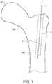
- a bone 10includes a fracture 2.
- the fracture 2separates the bone into portions 10A and 10B.
- a stabilizing wire 4may be used to hold bone portions together.
- the stabilizing wire 4may be any type of wire used to temporarily or permanently secure portions of bone together, such as Kirschner wires or Steinmann pins.
- the stabilizing wire 4is often placed in a fractured bone 10 prior to insertion of a more permanent bone implant, such as a bone screw, nail, or other fixation structure.
- the stabilizing wire 4may serve as a guide for a cannula, drill or bone implant.
- Various delivery apparatusescan be introduced over the stabilizing wire 4 to deliver a surgical substance, such as a bone void filler to the fractured area of the bone, or other target area of the anatomy.
- a surgical substancesuch as a bone void filler
- Such delivery apparatusesmay be elongated cannulas that carry the surgical substance from the fluid/substance source, to the target area of the anatomy, and may be such cannulas as described in U.S. patent application Ser. No. 13/270,072 , titled “Method and Device for Delivering Medicine to Bone," filed Oct. 10, 2011.
- a multichannel cannula 200 having two or more channelsmay be introduced over the stabilizing wire 4 to deliver substances to the interior of bone 10.
- the multichannel cannulamay be introduced over the stabilizing wire 4 after creation of hole 6, but prior to placement of a bone implant into the hole 6.
- a first channel of the multichannel cannulareceives the stabilizing wire 4.
- the other channels of the multichannel cannulamay be used for delivering the surgical substance to the interior of bone 10.
- the substance delivered using the multichannel cannulas described hereinmay be any type of substance a user desires to deliver to the interior of a bone, including growth factors or medication such as bone void fillers, calcium phosphate paste, an antibiotic, pain medication, or a chemotherapeutic agent.
- the cannulas described hereincan be made of any material suitable for placement into a bone without harmful effects on the patient.
- the cannulais made of stainless steel or other type of metal.
- the cannulamay be made of a rigid plastic, such as polyethylketone, that cannot be easily bent or manipulated into alternative configurations.
- a rigid cannulamay be advantageous to provide stability when introducing the cannula into a hole 6 in a bone 10.
- a rigid cannulaprovides stability for various procedures that a more flexible cannula may not provide. For example, if a surgeon desires to use a plunger or other device to push a substance from the cannula and into the bone, a rigid cannula may be more desirable.
- a rigid cannulais able to withstand more significant forces than a flexible cannula (e.g., forces applied to the cannula by a delivery device or a suction device, and the forces resulting from movement of substances through the channels and through any open portals in the cannula).
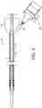
- the cannulae that may be used to deliver the substance to the boneare substantially elongated structures with two or more channels.
- the multichannel cannula 200 depicted in FIG. 2 and described hereinincludes a first channel 201 having an open proximal end 224 and an open distal end 222. The open proximal end and open distal end allow the first channel to be threaded over a stabilizing wire 4.
- the first channel 201is configured to receive a stabilizing wire 4.
- the first channel 201is substantially cylindrical and has a diameter slightly larger than the diameter of the stabilizing wire.
- the side wall of the cylindrical first channel(as distinguished from the open ends of the first channel) may be continuous, meaning there are no open portals or other openings along the side wall of the first channel. In one example, liquid cannot penetrate the side wall of the first channel.
- the multichannel cannula shown in FIG. 2further includes a second channel 202.
- the second channel 202includes at least one inlet portal 220 and at least one exit portal (e.g., open distal end 210).
- the inlet portal 220 of the second channel 202serves as an inlet for the surgical substance to be delivered to the interior of a bone.
- the exit portal 210 of the second channelserves as an outlet for the substance.
- the inlet portal and exit portal of the second channelare thus in fluid communication to allow substances or materials to be delivered to the interior of a bone.
- multichannel cannula 200may also include a cap 320.
- the cap 320has a housing portion with a channel for coupling to a portion of the proximal end of cannula 200.
- the channel of the cap 320may extend from first end through a second end of the housing portion for receiving the stabilizing wire 4 therethrough.
- the cap 320may be affixed to the multichannel cannula 200, such as during production of the cannula 200.
- the cap 320may be removable.
- the cap 320may be positioned at the site of the hole in the bone, such as hole 6, in order to serve as a plug.
- cap 320can plug the hole 6 and may prevent irrigation or other substance being delivered to the site from coming back up through the hole 6 in the bone.
- a separate temporary plug or sealmay be added to the cannula to plug the hole 6 in the bone.
- cap 320also has a delivery portal 322.
- the delivery portal 322is coupled to an inlet portal of the second channel 202 such that a substance can flow from the delivery portal 322, through the inlet portal, and into the second channel 202.
- Various delivery systemscan be coupled to the delivery portal 322 to assist in delivering substances to the second channel 202 of multichannel cannula 200, and ultimately to the bone.
- Tubingmay be used to connect the delivery system to the delivery portal 322.
- the type of delivery system selected by a usermay depend on the type of substance to be delivered to the bone.
- One such delivery systemis a mixing and delivery system 400, as depicted in FIGS. 3-7 . While shown in use with the cannula 200, the delivery system 400 according to various exemplary embodiments can also be used with other delivery apparatuses, other than the cannulas shown and described above, such as a different cannula, a catheter, or a delivery needle.
- the mixing and delivery system 400includes a flexible, compressible tube 401.
- the compressible tube 401includes a reservoir 402 that is configured to hold and/or receive elements to be mixed together for forming a surgical substance.
- the elements for forming a bone void fillerare a particulate substance and a mixing liquid, such as a bulking agent and a reacting agent.
- one of the elementsmay be a component containing stem cells or bone marrow aspirate that may be mixed with a second element at the time of harvest, or prior to delivery.
- the first elementmay be a prepared paste or fluid, to be mixed with a second fluid element.
- the reservoir 402is of sufficient size and shape such that the mixing of the elements to form the surgical substance can take place therein.
- the reservoir 402is in fluid communication with at least one portal 404 of the compressible tube 401.
- the portal 404serves as both an inlet and an exit portal.
- the portal 404, or an alternative inlet portion such as a sealable opening,allows for introduction of, for example, the mixing liquid to the particulate solid held in the reservoir 402.
- the portal 404is preferably sealable so as to contain the first element, such as a particulate solid, and/or the surgical substance within the reservoir when introduction of the second element, such as the mixing liquid, or delivery of the surgical substance is not taking place.
- the compressible tube 401also has an exit portal, which may also be portal 404, through which the mixed and prepared surgical substance is delivered to a delivery apparatus, such as the cannula 200 discussed herein, directly to a target area, or to another device to hold the surgical substance.
- a delivery apparatussuch as the cannula 200 discussed herein, directly to a target area, or to another device to hold the surgical substance.
- the portal 404is both the inlet and the exit portal.
- the portal 404serves as an exit portal only, and the opposing end 405 is open, or able to be opened and resealed, such that introduction of the mixing liquid and performance of the mixing (described below) can be accomplished through the opposing end 405.
- the compressible tube 401has a false bottom, wherein the tube has an internal partition constituting a wall of the reservoir 402 portion of the compressible tube 401.
- the reservoir 402comprises the entirety of the area within the compressible tube 401 structure.
- the compressible tube 401in preferred embodiments, is made of a transparent material to enable visualization of the mixing of the surgical substance. In this way, a practitioner is able to witness and guide the progress of the mixing and determine when the surgical substance is appropriately formed.
- mixing and delivery system 400also includes a mixing apparatus 410.
- the mixing apparatus 410may be a blender or other device suitable for mixing the particulate solid with the mixing liquid.
- the mixing apparatus 410may be any blender, agitator, or mixer suitable for mixing medical substances.
- the mixing apparatus 410includes a handle/housing portion 412 for managing and manipulating the mixing apparatus 410 and a mixing portion 414.
- the mixing portion 414is an elongated portion that is configured to be received through the inlet portion of the compressible tube 401, such that the mixing and forming of the surgical substance can take place within the reservoir 402.
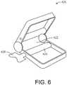
- Mixing and delivery system 400may also include a compressing device, such as the compressing device 420 shown in FIG. 6 .
- the compressing device 420may have a slotted portion 422 configured to receive a portion of the compressible tube 401 therethrough.
- the compressing device 420may be separate from the compressible tube 401, or may be integrated into the compressible tube 401.
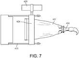
- the compressing device 420is configured to move along the length of the compressible tube 401, compressing the compressible tube 401 so as to force the surgical substance through the exit portal of the compressible tube 401, as shown in FIG. 7 , and to the cannula, catheter, needle, or other chosen delivery apparatus.
- the compressing device 420may have a rolling key 424 that moves along or rolls the compressible tube 401 by way of manual manipulation of a key flange 426, and that causes the compression of the compressible tube 401 and forces the surgical substance from the reservoir 402.
- One method of mixing and delivering a surgical substance to boneincludes providing a compressible delivery tube, such as compressible tube 401, wherein the compressible tube 401 has a reservoir 402.
- the compressible tube 401may be provided with a first element therein, such as particulate solid or a prepared paste or fluid, or the first element may be introduced into the reservoir 402 through the portal 404.
- a mixing apparatus 410such as a blender, mixing, or agitator, is introduced to the reservoir 402 of the compressible tube 401 after or during introduction of a second element, such as the mixing liquid to the reservoir 402.
- the second elementsuch as the mixing liquid, is introduced through the portal 404.
- the mixing apparatus 410likewise, is introduced through the portal 404.
- the methodfurther includes moving the surgical substance through the exit port of the compressible tube 401 for delivery to the body. Delivery to the body may take place through a cannula as described above, or may alternatively take place through a catheter, delivery needle, or other delivery apparatus. Moving the surgical substance through the exit port of the compressible tube 401 may use a compressing device 420 which moves along the length of the compressible tube 401 to force the surgical substance through the portal 404 of the compressible tube 401.
Landscapes
- Health & Medical Sciences (AREA)
- Life Sciences & Earth Sciences (AREA)
- Surgery (AREA)
- Orthopedic Medicine & Surgery (AREA)
- Animal Behavior & Ethology (AREA)
- General Health & Medical Sciences (AREA)
- Veterinary Medicine (AREA)
- Engineering & Computer Science (AREA)
- Biomedical Technology (AREA)
- Heart & Thoracic Surgery (AREA)
- Public Health (AREA)
- Chemical & Material Sciences (AREA)
- Chemical Kinetics & Catalysis (AREA)
- Nuclear Medicine, Radiotherapy & Molecular Imaging (AREA)
- Molecular Biology (AREA)
- Medical Informatics (AREA)
- Fluid Mechanics (AREA)
- Vascular Medicine (AREA)
- Anesthesiology (AREA)
- Hematology (AREA)
- Pathology (AREA)
- Physics & Mathematics (AREA)
- Prostheses (AREA)
- Surgical Instruments (AREA)
- Materials For Medical Uses (AREA)
Description
- The present invention relates generally to the field of devices and methods for delivering substances, more particularly, the present invention concerns devices and methods for mixing and delivering substances.
- Present methods of preparing a viscous surgical substance, such as a bone void filler, to be introduced to fractured or injured bones involve cumbersome, multi-step processes. The process to form such a surgical substance requires mixing a bulking agent with a reacting agent to form the substance at the time of use. Such methods may require mixing the elements in a separate mixing container and manually transferring the material to a delivery container, such as a syringe. Not only is this method laborious, but can also create a mess at the mixing site. The amount of time used to mix the elements and make this transfer can also add to the increased viscosity of the substance, and make compression of the syringe or delivery device for delivering the substance to a cannula or other delivery apparatus more difficult. Syringes can fail, which may result in waste of the substance therein, or require a further transfer and additional clean-up. Furthermore, the compressive forces necessary to make the transfer from the syringe can be difficult for many users and preparers of the material.
US 2008/0039855 discloses a delivery device for bone cement with a receiving end and a dispensing end which are at opposing ends of a mixing bag contained within the delivery device. The delivery device also includes a vane which is fixed in the mixing bag.US 5,951,160 discloses a syringe-type container that has a proximal end, that receives mixing rods and mixing materials, and a distal end through which bone cement is delivered. - Various embodiments of the invention described herein allow for mixing and delivery of a substance (e.g., medication or bone void filler).
- One embodiment of the invention relates to method of mixing and delivering a substance including providing a compressible tube having a reservoir and a port; introducing a mixing apparatus into the reservoir through the port; mixing a first substance element and a second substance element using the mixing apparatus to form the substance within the reservoir of the compressible tube. The method further includes delivering the substance through the port in the compressible tube using a compressing device.
- The method may also include providing the particulate solid in the reservoir of the compressible tube, or alternatively, introducing the particulate solid into the reservoir of the compressible tube. The method may also include introducing the mixing liquid into the reservoir of the compressible tube.
- The method may also include moving the substance through the port and into a delivery apparatus. The delivery apparatus may be a cannula.
- The substance may be a bone void filler. The compressing device may be positioned on the compressible tube and the method may further include moving the compressing device along the compressible tube to empty the substance from the compressible tube. The compressing device may include a rolling key to roll the compressible tube to empty the substance from the compressible tube.
- Another embodiment of the invention relates to a mixing and delivery system including a compressible tube having a reservoir configured for mixing and holding a surgical substance. The compressible tube includes a single port for accommodating the introduction of an element of the surgical substance into the compressible tube and for enabling the delivery of the surgical substance to a target portion of an anatomy. The system further includes a mixing apparatus configured to be received through the port of the compressible tube for mixing the elements of the surgical substance to form the surgical substance.
- The mixing and delivery system may also include a compressing device configured to move along the compressible tube and force the surgical substance through the port. The port may be configured to engage with a delivery apparatus. The delivery apparatus may be a cannula. The inlet portion may be sealable.
- The reservoir of the compressible tube may contain a particulate substance and the fluid introduced through the port may be a mixing liquid. The surgical substance may be a bone void filler.
- The disclosure will become more fully understood from the following detailed description, taken in conjunction with the accompanying figures, wherein like reference numerals refer to like elements, in which:
FIG. 1 illustrates a bone with a stabilizing wire and a hole in the bone around the stabilizing wire.FIG. 2 illustrates the bone and stabilizing wire shown inFIG. 1 with a cannula introduced over the stabilizing wire, for delivery of a surgical substance to a fracture in the bone.FIG. 3 illustrates a longitudinal section view of a cannula with a cap used in connection with a delivery system according to an exemplary embodiment.FIG. 4 illustrates a compressible delivery tube according to an exemplary embodiment.FIG. 5 illustrates a mixing apparatus according to an exemplary embodiment.FIG. 6 illustrates a pinching apparatus to be used with the delivery system according to an exemplary embodiment.FIG. 7 illustrates a pinching apparatus used on the compressible tube in accordance with an exemplary embodiment of the delivery system.- Referring to
FIG. 1 , abone 10 includes afracture 2. Thefracture 2 separates the bone intoportions wire 4 may be used to hold bone portions together. The stabilizingwire 4 may be any type of wire used to temporarily or permanently secure portions of bone together, such as Kirschner wires or Steinmann pins. The stabilizingwire 4 is often placed in a fracturedbone 10 prior to insertion of a more permanent bone implant, such as a bone screw, nail, or other fixation structure. In addition to stabilizing thebone portions wire 4 may serve as a guide for a cannula, drill or bone implant. - Various delivery apparatuses can be introduced over the stabilizing
wire 4 to deliver a surgical substance, such as a bone void filler to the fractured area of the bone, or other target area of the anatomy. Such delivery apparatuses may be elongated cannulas that carry the surgical substance from the fluid/substance source, to the target area of the anatomy, and may be such cannulas as described inU.S. patent application Ser. No. 13/270,072 - Referring to
FIG. 2 , amultichannel cannula 200 having two or more channels may be introduced over the stabilizingwire 4 to deliver substances to the interior ofbone 10. The multichannel cannula may be introduced over the stabilizingwire 4 after creation ofhole 6, but prior to placement of a bone implant into thehole 6. A first channel of the multichannel cannula receives the stabilizingwire 4. The other channels of the multichannel cannula may be used for delivering the surgical substance to the interior ofbone 10. The substance delivered using the multichannel cannulas described herein may be any type of substance a user desires to deliver to the interior of a bone, including growth factors or medication such as bone void fillers, calcium phosphate paste, an antibiotic, pain medication, or a chemotherapeutic agent. - The cannulas described herein can be made of any material suitable for placement into a bone without harmful effects on the patient. In one embodiment, the cannula is made of stainless steel or other type of metal. The cannula may be made of a rigid plastic, such as polyethylketone, that cannot be easily bent or manipulated into alternative configurations. A rigid cannula may be advantageous to provide stability when introducing the cannula into a
hole 6 in abone 10. Furthermore, a rigid cannula provides stability for various procedures that a more flexible cannula may not provide. For example, if a surgeon desires to use a plunger or other device to push a substance from the cannula and into the bone, a rigid cannula may be more desirable. As another example, a rigid cannula is able to withstand more significant forces than a flexible cannula (e.g., forces applied to the cannula by a delivery device or a suction device, and the forces resulting from movement of substances through the channels and through any open portals in the cannula). - The cannulae that may be used to deliver the substance to the bone are substantially elongated structures with two or more channels. The
multichannel cannula 200 depicted inFIG. 2 and described herein includes afirst channel 201 having an openproximal end 224 and an opendistal end 222. The open proximal end and open distal end allow the first channel to be threaded over a stabilizingwire 4. Thus, thefirst channel 201 is configured to receive a stabilizingwire 4. In one embodiment, thefirst channel 201 is substantially cylindrical and has a diameter slightly larger than the diameter of the stabilizing wire. The side wall of the cylindrical first channel (as distinguished from the open ends of the first channel) may be continuous, meaning there are no open portals or other openings along the side wall of the first channel. In one example, liquid cannot penetrate the side wall of the first channel. - The multichannel cannula shown in
FIG. 2 further includes asecond channel 202. Thesecond channel 202 includes at least oneinlet portal 220 and at least one exit portal (e.g., open distal end 210). In some methods described herein, theinlet portal 220 of thesecond channel 202 serves as an inlet for the surgical substance to be delivered to the interior of a bone. In these examples, theexit portal 210 of the second channel serves as an outlet for the substance. The inlet portal and exit portal of the second channel are thus in fluid communication to allow substances or materials to be delivered to the interior of a bone. - As shown in
FIG. 3 ,multichannel cannula 200 may also include acap 320. Thecap 320 has a housing portion with a channel for coupling to a portion of the proximal end ofcannula 200. The channel of thecap 320 may extend from first end through a second end of the housing portion for receiving the stabilizingwire 4 therethrough. Thecap 320 may be affixed to themultichannel cannula 200, such as during production of thecannula 200. In an alternative example, thecap 320 may be removable. Thecap 320 may be positioned at the site of the hole in the bone, such ashole 6, in order to serve as a plug. In this way,cap 320 can plug thehole 6 and may prevent irrigation or other substance being delivered to the site from coming back up through thehole 6 in the bone. In another example, a separate temporary plug or seal may be added to the cannula to plug thehole 6 in the bone. In the example shown,cap 320 also has adelivery portal 322. Thedelivery portal 322 is coupled to an inlet portal of thesecond channel 202 such that a substance can flow from thedelivery portal 322, through the inlet portal, and into thesecond channel 202. - Various delivery systems can be coupled to the
delivery portal 322 to assist in delivering substances to thesecond channel 202 ofmultichannel cannula 200, and ultimately to the bone. Tubing may be used to connect the delivery system to thedelivery portal 322. The type of delivery system selected by a user may depend on the type of substance to be delivered to the bone. - One such delivery system is a mixing and
delivery system 400, as depicted inFIGS. 3-7 . While shown in use with thecannula 200, thedelivery system 400 according to various exemplary embodiments can also be used with other delivery apparatuses, other than the cannulas shown and described above, such as a different cannula, a catheter, or a delivery needle. - As shown in
FIG. 4 , the mixing anddelivery system 400 includes a flexible,compressible tube 401. Thecompressible tube 401 includes areservoir 402 that is configured to hold and/or receive elements to be mixed together for forming a surgical substance. In one embodiment, the elements for forming a bone void filler are a particulate substance and a mixing liquid, such as a bulking agent and a reacting agent. In another embodiment, one of the elements may be a component containing stem cells or bone marrow aspirate that may be mixed with a second element at the time of harvest, or prior to delivery. In yet another embodiment, the first element may be a prepared paste or fluid, to be mixed with a second fluid element. Thereservoir 402 is of sufficient size and shape such that the mixing of the elements to form the surgical substance can take place therein. Thereservoir 402 is in fluid communication with at least oneportal 404 of thecompressible tube 401. The portal 404 serves as both an inlet and an exit portal. The portal 404, or an alternative inlet portion such as a sealable opening, allows for introduction of, for example, the mixing liquid to the particulate solid held in thereservoir 402. The portal 404 is preferably sealable so as to contain the first element, such as a particulate solid, and/or the surgical substance within the reservoir when introduction of the second element, such as the mixing liquid, or delivery of the surgical substance is not taking place. Thecompressible tube 401 also has an exit portal, which may also be portal 404, through which the mixed and prepared surgical substance is delivered to a delivery apparatus, such as thecannula 200 discussed herein, directly to a target area, or to another device to hold the surgical substance. - In the embodiment, the portal 404 is both the inlet and the exit portal. In constructions which do not fall under the claims, the portal 404 serves as an exit portal only, and the
opposing end 405 is open, or able to be opened and resealed, such that introduction of the mixing liquid and performance of the mixing (described below) can be accomplished through theopposing end 405. - In certain embodiments, the
compressible tube 401 has a false bottom, wherein the tube has an internal partition constituting a wall of thereservoir 402 portion of thecompressible tube 401. In other embodiments, thereservoir 402 comprises the entirety of the area within thecompressible tube 401 structure. Thecompressible tube 401, in preferred embodiments, is made of a transparent material to enable visualization of the mixing of the surgical substance. In this way, a practitioner is able to witness and guide the progress of the mixing and determine when the surgical substance is appropriately formed. - Referring to
FIG. 5 , in an exemplary embodiment, mixing anddelivery system 400 also includes amixing apparatus 410. The mixingapparatus 410 may be a blender or other device suitable for mixing the particulate solid with the mixing liquid. The mixingapparatus 410 may be any blender, agitator, or mixer suitable for mixing medical substances. As shown in the embodiment ofFIG. 5 , the mixingapparatus 410 includes a handle/housing portion 412 for managing and manipulating themixing apparatus 410 and a mixingportion 414. The mixingportion 414, as shown, is an elongated portion that is configured to be received through the inlet portion of thecompressible tube 401, such that the mixing and forming of the surgical substance can take place within thereservoir 402. - Mixing and
delivery system 400 may also include a compressing device, such as thecompressing device 420 shown inFIG. 6 . Thecompressing device 420 may have a slottedportion 422 configured to receive a portion of thecompressible tube 401 therethrough. Thecompressing device 420 may be separate from thecompressible tube 401, or may be integrated into thecompressible tube 401. Thecompressing device 420 is configured to move along the length of thecompressible tube 401, compressing thecompressible tube 401 so as to force the surgical substance through the exit portal of thecompressible tube 401, as shown inFIG. 7 , and to the cannula, catheter, needle, or other chosen delivery apparatus. In particular, thecompressing device 420 may have a rolling key 424 that moves along or rolls thecompressible tube 401 by way of manual manipulation of akey flange 426, and that causes the compression of thecompressible tube 401 and forces the surgical substance from thereservoir 402. - One method of mixing and delivering a surgical substance to bone, such as a bone void filler, according to an exemplary embodiment includes providing a compressible delivery tube, such as
compressible tube 401, wherein thecompressible tube 401 has areservoir 402. Thecompressible tube 401 may be provided with a first element therein, such as particulate solid or a prepared paste or fluid, or the first element may be introduced into thereservoir 402 through the portal 404. A mixingapparatus 410, such as a blender, mixing, or agitator, is introduced to thereservoir 402 of thecompressible tube 401 after or during introduction of a second element, such as the mixing liquid to thereservoir 402. As described above, the second element, such as the mixing liquid, is introduced through the portal 404. The mixingapparatus 410, likewise, is introduced through the portal 404. The method further includes moving the surgical substance through the exit port of thecompressible tube 401 for delivery to the body. Delivery to the body may take place through a cannula as described above, or may alternatively take place through a catheter, delivery needle, or other delivery apparatus. Moving the surgical substance through the exit port of thecompressible tube 401 may use acompressing device 420 which moves along the length of thecompressible tube 401 to force the surgical substance through the portal 404 of thecompressible tube 401.
Claims (14)
- A method of mixing and delivering a substance, comprising:providing a compressible tube (401) having a reservoir (402) and a port (404);introducing a mixing apparatus (410) into the reservoir (402) through the port (404);mixing a first substance element and a second substance element using the mixing apparatus (410) to form the substance within the reservoir (402) of the compressible tube (401);delivering the substance through the port (404) in the compressible tube (401) and into a delivery apparatus (200) using a compressing device (420).
- The method of claim 1, wherein the first substance element is a particulate solid and the second substance element is a mixing liquid.
- The method of claim 1, further comprising introducing the first element into the reservoir (402) of the compressible tube (401), and/or introducing the second element into the reservoir (402) of the compressible tube (401).
- The method of claim 1, further comprising moving the substance through the port (404) wherein the delivery apparatus (200) is a cannula.
- The method of claim 1, wherein the substance is a bone void filler.
- The method of claim 1, wherein the compressing device (420) is positioned on the compressible tube (401) and wherein the method further comprises moving the compressing device (420) along the compressible tube (401) to empty the substance from the compressible tube (401), optionally wherein the compressing device (420) comprises a rolling key (424) to roll the compressible tube (401) to empty the substance from the compressible tube (401).
- The method of claim 1, wherein the second element is introduced to the reservoir (402) through a sealable inlet portion.
- The method of claim 1, wherein the first element comprises one of stem cells and a bone marrow aspirate, and/or wherein the first element is a paste material and the second material is a mixing liquid.
- A mixing and delivery system (400), comprising:
a compressible tube (401) comprising:a reservoir (402) configured for mixing and holding a surgical substance;a single port (404) for accommodating introduction of an element of the surgical substance into the compressible tube (401) and for enabling the delivery of the surgical substance to a target portion of an anatomy; anda mixing apparatus (410) configured to be received through the port (404) of the compressible tube (401) for mixing elements of the surgical substance to form the surgical substance. - The mixing and delivery system (400) of claim 9, further comprising a compressing device (420) configured to move along the compressible tube (401) and force the surgical substance through the port (404).
- The mixing and delivery system (400) of claim 9, wherein the port (404) is sealable.
- The mixing and delivery system (400) of claim 9, wherein the reservoir (402) contains a surgical substance, wherein the surgical substance is a bone void filler.
- The mixing and delivery system (400) of claim 9, wherein the reservoir (402) of the compressible tube (401) contains a particulate substance and an element introduced through the port (404) is a mixing liquid.
- The mixing and delivery system (400) of claim 9, further comprising a plurality of compressible tubes (401).
Applications Claiming Priority (2)
| Application Number | Priority Date | Filing Date | Title |
|---|---|---|---|
| US14/184,478US10653470B2 (en) | 2014-02-19 | 2014-02-19 | Compressible mixing and delivery system for medical substances |
| PCT/US2015/014216WO2015126612A1 (en) | 2014-02-19 | 2015-02-03 | Compressible mixing and delivery system for medical substances |
Publications (2)
| Publication Number | Publication Date |
|---|---|
| EP3107470A1 EP3107470A1 (en) | 2016-12-28 |
| EP3107470B1true EP3107470B1 (en) | 2020-01-22 |
Family
ID=52484584
Family Applications (1)
| Application Number | Title | Priority Date | Filing Date |
|---|---|---|---|
| EP15705442.0AActiveEP3107470B1 (en) | 2014-02-19 | 2015-02-03 | Compressible mixing and delivery system for medical substances |
Country Status (3)
| Country | Link |
|---|---|
| US (2) | US10653470B2 (en) |
| EP (1) | EP3107470B1 (en) |
| WO (1) | WO2015126612A1 (en) |
Families Citing this family (1)
| Publication number | Priority date | Publication date | Assignee | Title |
|---|---|---|---|---|
| US11439432B2 (en) | 2020-04-09 | 2022-09-13 | Spinal Generations, Llc | Handle attachment for fluid delivery needle and method of use thereof |
Family Cites Families (80)
| Publication number | Priority date | Publication date | Assignee | Title |
|---|---|---|---|---|
| US3310051A (en) | 1963-12-10 | 1967-03-21 | Rudolf R Schulte | Surgical reservoir for implantation beneath the skin |
| US3870198A (en)* | 1973-08-13 | 1975-03-11 | Milton J Cohen | Twistable bag type dispenser |
| US4015945A (en)* | 1976-03-15 | 1977-04-05 | Zimmer, U.S.A. Inc. | Device for mixing bone cement |
| US4277184A (en)* | 1979-08-14 | 1981-07-07 | Alan Solomon | Disposable orthopedic implement and method |
| US4399814A (en) | 1981-04-27 | 1983-08-23 | Massachusetts Institute Of Technology | Method and apparatus for pressure-coated bones |
| US4464178A (en) | 1981-11-25 | 1984-08-07 | Dalton Michael J | Method and apparatus for administration of fluids |
| CA1227902A (en) | 1984-04-02 | 1987-10-13 | Raymond G. Tronzo | Fenestrated hip screw and method of augmented internal fixation |
| US5133755A (en) | 1986-01-28 | 1992-07-28 | Thm Biomedical, Inc. | Method and apparatus for diodegradable, osteogenic, bone graft substitute device |
| US4653487A (en) | 1986-01-29 | 1987-03-31 | Maale Gerhard E | Intramedullary rod assembly for cement injection system |
| US4760844A (en) | 1986-03-21 | 1988-08-02 | Ace Medical Company | Cannulated screw dye injector |
| US4772261A (en) | 1987-01-29 | 1988-09-20 | Board Of Regents, The University Of Texas System | Intramedullary catheter |
| EP0305417B1 (en) | 1987-02-20 | 1995-06-28 | DRAENERT, Klaus, Dr.med. | Suction drainage-bone screw |
| DE8810295U1 (en) | 1988-08-13 | 1988-10-13 | Stanelle, Karl-Heinz, 7129 Güglingen | Filter cartridge |
| SE462315B (en) | 1989-05-03 | 1990-06-11 | Surgitec Ab | DEVICE FOR MANUFACTURING BENCEMENT |
| US5203770A (en) | 1990-04-20 | 1993-04-20 | Regents Of The University Of Minnesota | Method and apparatus for catheterization |
| US4976692A (en) | 1990-09-13 | 1990-12-11 | Travenol Laboratories (Israel) Ltd. | Catheter particularly useful for inducing labor and/or for the application of a pharmaceutical substance to the cervix of the uterus |
| US5122114A (en) | 1991-02-01 | 1992-06-16 | Board Of Regents, University Of Texas System | Method of using intramedullary catheter |
| JPH0596012A (en) | 1991-10-07 | 1993-04-20 | Olympus Optical Co Ltd | Thermotherapic device |
| US5332398A (en) | 1992-02-01 | 1994-07-26 | Board Of Regents, The University Of Texas System | Intramedullary catheter |
| US5433718A (en) | 1992-08-20 | 1995-07-18 | Brinker; Mark | Antibiotic eluding intramedullary nail apparatus |
| US5372583A (en) | 1992-11-25 | 1994-12-13 | Cardiopulmonary Specialities, Inc. | Bone marrow infuser and method of use |
| US5425723A (en) | 1993-12-30 | 1995-06-20 | Boston Scientific Corporation | Infusion catheter with uniform distribution of fluids |
| AU681761B2 (en) | 1994-02-15 | 1997-09-04 | Biosearch Italia S.P.A. | Central venous catheters loaded with antibiotics of the ramoplanin group preventing development of catheter related infections |
| GB9403362D0 (en)* | 1994-02-22 | 1994-04-13 | Summit Medical Ltd | Bone cement mixing apparatus |
| US5769899A (en) | 1994-08-12 | 1998-06-23 | Matrix Biotechnologies, Inc. | Cartilage repair unit |
| US5702372A (en) | 1995-02-08 | 1997-12-30 | Medtronic, Inc. | Lined infusion catheter |
| US6077265A (en) | 1995-04-21 | 2000-06-20 | Werding; Gerd | Nail for fixing the position and shape of broken long bones |
| US5562625A (en) | 1995-05-02 | 1996-10-08 | Stefancin, Jr.; Ronald J. | Reusasble syringe with a disposable needle sheath |
| US5681289A (en) | 1995-08-14 | 1997-10-28 | Medicinelodge Inc. | Chemical dispensing system |
| US5749883A (en) | 1995-08-30 | 1998-05-12 | Halpern; David Marcos | Medical instrument |
| US5586821A (en)* | 1995-10-10 | 1996-12-24 | Zimmer, Inc. | Bone cement preparation kit |
| US5871484A (en) | 1995-11-09 | 1999-02-16 | General Orthopedics | Apparatus and method for administering a biologically active substance to a bone |
| US5800407A (en) | 1995-12-21 | 1998-09-01 | Eldor; Joseph | Multiple hole epidural catheter |
| US5876116A (en)* | 1996-11-15 | 1999-03-02 | Barker; Donald | Integrated bone cement mixing and dispensing system |
| US6783514B2 (en) | 1997-01-31 | 2004-08-31 | United States Surgical Corporation | Fibrin sealant applicator |
| US5951160A (en) | 1997-11-20 | 1999-09-14 | Biomet, Inc. | Method and apparatus for packaging, mixing and delivering bone cement |
| US6364856B1 (en) | 1998-04-14 | 2002-04-02 | Boston Scientific Corporation | Medical device with sponge coating for controlled drug release |
| US6461327B1 (en) | 1998-08-07 | 2002-10-08 | Embol-X, Inc. | Atrial isolator and method of use |
| US6214012B1 (en) | 1998-11-13 | 2001-04-10 | Harrington Arthritis Research Center | Method and apparatus for delivering material to a desired location |
| US6019761A (en) | 1998-12-23 | 2000-02-01 | Gustilo; Ramon B. | Intramedullary nail and method of use |
| US6210376B1 (en) | 1999-04-08 | 2001-04-03 | New York University | Cannulated delivery pin |
| US6048343A (en) | 1999-06-02 | 2000-04-11 | Mathis; John M. | Bone screw system |
| US6220888B1 (en) | 1999-06-25 | 2001-04-24 | Hubbell Incorporated | Quick disconnect cable connector device with integral body and strain relief structure |
| US6387098B1 (en) | 1999-10-21 | 2002-05-14 | Peter Alexander Cole | Intramedullary catheter nail apparatus and method |
| US6929633B2 (en) | 2000-01-25 | 2005-08-16 | Bacchus Vascular, Inc. | Apparatus and methods for clot dissolution |
| US6286670B1 (en)* | 2000-03-14 | 2001-09-11 | Biomet, Inc. | Method and apparatus for mixing a compound utilizing a gas permeable barrier |
| US6565572B2 (en) | 2000-04-10 | 2003-05-20 | Sdgi Holdings, Inc. | Fenestrated surgical screw and method |
| US6821298B1 (en) | 2000-04-18 | 2004-11-23 | Roger P. Jackson | Anterior expandable spinal fusion cage system |
| US20020169507A1 (en) | 2000-12-14 | 2002-11-14 | David Malone | Interbody spine fusion cage |
| US6520384B2 (en) | 2001-04-30 | 2003-02-18 | Ketan C. Mehta | Apparatus and method for nasal rinse |
| AUPR553701A0 (en) | 2001-06-07 | 2001-07-12 | Royal Alexandra Hospital For Children, The | A device for the delivery of a drug to a fractured bone |
| US6679890B2 (en) | 2001-08-28 | 2004-01-20 | Joseph Y. Margulies | Method and apparatus for augmentation of the femoral neck |
| US7488320B2 (en) | 2001-11-01 | 2009-02-10 | Renova Orthopedics, Llc | Orthopaedic implant fixation using an in-situ formed anchor |
| US6960215B2 (en) | 2002-05-08 | 2005-11-01 | Boston Scientific Scimed, Inc. | Tactical detachable anatomic containment device and therapeutic treatment system |
| DE10242984B4 (en)* | 2002-09-17 | 2010-09-23 | Sanatis Gmbh | Device for producing mixtures of two components |
| US7354442B2 (en) | 2003-05-05 | 2008-04-08 | Warsaw Orthopedic, Inc. | Bone anchor and methods of using the same |
| WO2005000090A2 (en) | 2003-05-30 | 2005-01-06 | Medi-Screw, Inc. | Medical implant systems |
| US7608062B2 (en) | 2003-07-15 | 2009-10-27 | Spinal Generations, Llc | Method and device for delivering medicine to bone |
| US7527611B2 (en) | 2003-07-15 | 2009-05-05 | Spinal Generations, Llc | Method and device for delivering medicine to bone |
| US8870836B2 (en) | 2003-07-15 | 2014-10-28 | Spinal Generations, Llc | Method and device for delivering medicine to bone |
| US7575572B2 (en) | 2003-07-15 | 2009-08-18 | Spinal Generations, Llc | Method and device for delivering medicine to bone |
| US8062270B2 (en)* | 2003-07-15 | 2011-11-22 | Spinal Generations, Llc | Method and device for delivering medicine to bone |
| US8070785B2 (en) | 2003-09-16 | 2011-12-06 | Spineco, Inc. | Bone anchor prosthesis and system |
| CA2481663A1 (en)* | 2003-10-01 | 2005-04-01 | Biomet Deutschland Gmbh | Device for the mixing and discharge of liquid and pulverulent materials for medical use |
| WO2008039807A2 (en) | 2004-03-15 | 2008-04-03 | Bonwrx, Inc. | Materials and apparatus for in-situ bone repair |
| CN101065080B (en) | 2004-07-30 | 2021-10-29 | 德普伊新特斯产品有限责任公司 | Materials and Instruments for Manipulating Bone and Other Tissues |
| ES2318391T3 (en) | 2005-08-05 | 2009-05-01 | Biedermann Motech Gmbh | OSEO ANCHORAGE ELEMENT. |
| US8057090B1 (en) | 2005-08-31 | 2011-11-15 | Subrata Saha | Automated bone cement mixer |
| US20070233123A1 (en) | 2006-02-21 | 2007-10-04 | Osteomed, L.P. | Bone fixation device |
| US20080154229A1 (en)* | 2006-07-26 | 2008-06-26 | Lambert Systems, L.L.C. | Device And Method For Mixing And Delivering Bone Cement Precursors |
| TWM306498U (en) | 2006-08-10 | 2007-02-21 | Shih-Tseng Lee | Securing member, expansion anchroing screw set |
| FR2913876B1 (en) | 2007-03-20 | 2009-06-05 | Memometal Technologies Soc Par | OSTEOSYNTHESIS DEVICE |
| US8740954B2 (en) | 2007-12-19 | 2014-06-03 | Integral Spine Solutions, Inc. | Device and method for orthopedic fracture fixation |
| US8974505B2 (en) | 2008-06-16 | 2015-03-10 | Anna G. U. Sawa | Venting/pressure adjustment to aid in delivery of material into an anatomic region via a cannula |
| US20100042213A1 (en) | 2008-08-13 | 2010-02-18 | Nebosky Paul S | Drug delivery implants |
| US9616205B2 (en) | 2008-08-13 | 2017-04-11 | Smed-Ta/Td, Llc | Drug delivery implants |
| JP5774989B2 (en) | 2008-08-13 | 2015-09-09 | スメド−ティーエイ/ティーディー・エルエルシー | Orthopedic screw |
| KR101687435B1 (en) | 2009-07-06 | 2016-12-19 | 신세스 게엠바하 | Expandable fixation assemblies |
| WO2011063240A1 (en) | 2009-11-20 | 2011-05-26 | Knee Creations, Llc | Implantable devices for subchondral treatment of joint pain |
| US20150157378A1 (en)* | 2012-04-05 | 2015-06-11 | Nlt Spine Ltd. | Material delivery device |
- 2014
- 2014-02-19USUS14/184,478patent/US10653470B2/enactiveActive
- 2015
- 2015-02-03EPEP15705442.0Apatent/EP3107470B1/enactiveActive
- 2015-02-03WOPCT/US2015/014216patent/WO2015126612A1/enactiveApplication Filing
- 2020
- 2020-05-18USUS16/876,547patent/US11712278B2/enactiveActive
Non-Patent Citations (1)
| Title |
|---|
| None* |
Also Published As
| Publication number | Publication date |
|---|---|
| WO2015126612A1 (en) | 2015-08-27 |
| US11712278B2 (en) | 2023-08-01 |
| US20150230846A1 (en) | 2015-08-20 |
| EP3107470A1 (en) | 2016-12-28 |
| US10653470B2 (en) | 2020-05-19 |
| US20200275962A1 (en) | 2020-09-03 |
Similar Documents
| Publication | Publication Date | Title |
|---|---|---|
| US10335218B2 (en) | Multichannel cannula and methods for using same | |
| US7909833B2 (en) | Vertebroplasty device having a flexible plunger | |
| US7371241B2 (en) | Multi-use surgical cement dispenser apparatus and kit for same | |
| US7922690B2 (en) | Curable material delivery device | |
| US10398483B2 (en) | Multichannel cannula and methods for using same | |
| US8361032B2 (en) | Curable material delivery device with a rotatable supply section | |
| US8016834B2 (en) | Process and device for treating vertebral bodies | |
| US8083748B2 (en) | Device and method for mixing and dispensing a bone cement mixture | |
| US11712278B2 (en) | Compressible mixing and delivery system for medical substances | |
| EP3068322B1 (en) | Multichannel cannula | |
| AU2005204244B2 (en) | Multi-use surgical cement dispenser apparatus | |
| AU2008207386B2 (en) | Multi-use surgical cement dispenser apparatus |
Legal Events
| Date | Code | Title | Description |
|---|---|---|---|
| PUAI | Public reference made under article 153(3) epc to a published international application that has entered the european phase | Free format text:ORIGINAL CODE: 0009012 | |
| STAA | Information on the status of an ep patent application or granted ep patent | Free format text:STATUS: REQUEST FOR EXAMINATION WAS MADE | |
| 17P | Request for examination filed | Effective date:20160909 | |
| AK | Designated contracting states | Kind code of ref document:A1 Designated state(s):AL AT BE BG CH CY CZ DE DK EE ES FI FR GB GR HR HU IE IS IT LI LT LU LV MC MK MT NL NO PL PT RO RS SE SI SK SM TR | |
| AX | Request for extension of the european patent | Extension state:BA ME | |
| DAX | Request for extension of the european patent (deleted) | ||
| STAA | Information on the status of an ep patent application or granted ep patent | Free format text:STATUS: EXAMINATION IS IN PROGRESS | |
| 17Q | First examination report despatched | Effective date:20190308 | |
| GRAP | Despatch of communication of intention to grant a patent | Free format text:ORIGINAL CODE: EPIDOSNIGR1 | |
| STAA | Information on the status of an ep patent application or granted ep patent | Free format text:STATUS: GRANT OF PATENT IS INTENDED | |
| INTG | Intention to grant announced | Effective date:20190814 | |
| GRAS | Grant fee paid | Free format text:ORIGINAL CODE: EPIDOSNIGR3 | |
| GRAA | (expected) grant | Free format text:ORIGINAL CODE: 0009210 | |
| STAA | Information on the status of an ep patent application or granted ep patent | Free format text:STATUS: THE PATENT HAS BEEN GRANTED | |
| AK | Designated contracting states | Kind code of ref document:B1 Designated state(s):AL AT BE BG CH CY CZ DE DK EE ES FI FR GB GR HR HU IE IS IT LI LT LU LV MC MK MT NL NO PL PT RO RS SE SI SK SM TR | |
| REG | Reference to a national code | Ref country code:GB Ref legal event code:FG4D | |
| REG | Reference to a national code | Ref country code:CH Ref legal event code:EP | |
| REG | Reference to a national code | Ref country code:AT Ref legal event code:REF Ref document number:1226434 Country of ref document:AT Kind code of ref document:T Effective date:20200215 | |
| REG | Reference to a national code | Ref country code:IE Ref legal event code:FG4D | |
| REG | Reference to a national code | Ref country code:DE Ref legal event code:R096 Ref document number:602015045950 Country of ref document:DE | |
| REG | Reference to a national code | Ref country code:NL Ref legal event code:MP Effective date:20200122 | |
| REG | Reference to a national code | Ref country code:LT Ref legal event code:MG4D | |
| PG25 | Lapsed in a contracting state [announced via postgrant information from national office to epo] | Ref country code:NL Free format text:LAPSE BECAUSE OF FAILURE TO SUBMIT A TRANSLATION OF THE DESCRIPTION OR TO PAY THE FEE WITHIN THE PRESCRIBED TIME-LIMIT Effective date:20200122 Ref country code:PT Free format text:LAPSE BECAUSE OF FAILURE TO SUBMIT A TRANSLATION OF THE DESCRIPTION OR TO PAY THE FEE WITHIN THE PRESCRIBED TIME-LIMIT Effective date:20200614 Ref country code:NO Free format text:LAPSE BECAUSE OF FAILURE TO SUBMIT A TRANSLATION OF THE DESCRIPTION OR TO PAY THE FEE WITHIN THE PRESCRIBED TIME-LIMIT Effective date:20200422 Ref country code:FI Free format text:LAPSE BECAUSE OF FAILURE TO SUBMIT A TRANSLATION OF THE DESCRIPTION OR TO PAY THE FEE WITHIN THE PRESCRIBED TIME-LIMIT Effective date:20200122 Ref country code:RS Free format text:LAPSE BECAUSE OF FAILURE TO SUBMIT A TRANSLATION OF THE DESCRIPTION OR TO PAY THE FEE WITHIN THE PRESCRIBED TIME-LIMIT Effective date:20200122 | |
| PG25 | Lapsed in a contracting state [announced via postgrant information from national office to epo] | Ref country code:HR Free format text:LAPSE BECAUSE OF FAILURE TO SUBMIT A TRANSLATION OF THE DESCRIPTION OR TO PAY THE FEE WITHIN THE PRESCRIBED TIME-LIMIT Effective date:20200122 Ref country code:BG Free format text:LAPSE BECAUSE OF FAILURE TO SUBMIT A TRANSLATION OF THE DESCRIPTION OR TO PAY THE FEE WITHIN THE PRESCRIBED TIME-LIMIT Effective date:20200422 Ref country code:LV Free format text:LAPSE BECAUSE OF FAILURE TO SUBMIT A TRANSLATION OF THE DESCRIPTION OR TO PAY THE FEE WITHIN THE PRESCRIBED TIME-LIMIT Effective date:20200122 Ref country code:GR Free format text:LAPSE BECAUSE OF FAILURE TO SUBMIT A TRANSLATION OF THE DESCRIPTION OR TO PAY THE FEE WITHIN THE PRESCRIBED TIME-LIMIT Effective date:20200423 Ref country code:IS Free format text:LAPSE BECAUSE OF FAILURE TO SUBMIT A TRANSLATION OF THE DESCRIPTION OR TO PAY THE FEE WITHIN THE PRESCRIBED TIME-LIMIT Effective date:20200522 Ref country code:SE Free format text:LAPSE BECAUSE OF FAILURE TO SUBMIT A TRANSLATION OF THE DESCRIPTION OR TO PAY THE FEE WITHIN THE PRESCRIBED TIME-LIMIT Effective date:20200122 | |
| REG | Reference to a national code | Ref country code:CH Ref legal event code:PL | |
| REG | Reference to a national code | Ref country code:DE Ref legal event code:R097 Ref document number:602015045950 Country of ref document:DE | |
| REG | Reference to a national code | Ref country code:BE Ref legal event code:MM Effective date:20200229 | |
| PG25 | Lapsed in a contracting state [announced via postgrant information from national office to epo] | Ref country code:LT Free format text:LAPSE BECAUSE OF FAILURE TO SUBMIT A TRANSLATION OF THE DESCRIPTION OR TO PAY THE FEE WITHIN THE PRESCRIBED TIME-LIMIT Effective date:20200122 Ref country code:EE Free format text:LAPSE BECAUSE OF FAILURE TO SUBMIT A TRANSLATION OF THE DESCRIPTION OR TO PAY THE FEE WITHIN THE PRESCRIBED TIME-LIMIT Effective date:20200122 Ref country code:LU Free format text:LAPSE BECAUSE OF NON-PAYMENT OF DUE FEES Effective date:20200203 Ref country code:DK Free format text:LAPSE BECAUSE OF FAILURE TO SUBMIT A TRANSLATION OF THE DESCRIPTION OR TO PAY THE FEE WITHIN THE PRESCRIBED TIME-LIMIT Effective date:20200122 Ref country code:SM Free format text:LAPSE BECAUSE OF FAILURE TO SUBMIT A TRANSLATION OF THE DESCRIPTION OR TO PAY THE FEE WITHIN THE PRESCRIBED TIME-LIMIT Effective date:20200122 Ref country code:CZ Free format text:LAPSE BECAUSE OF FAILURE TO SUBMIT A TRANSLATION OF THE DESCRIPTION OR TO PAY THE FEE WITHIN THE PRESCRIBED TIME-LIMIT Effective date:20200122 Ref country code:RO Free format text:LAPSE BECAUSE OF FAILURE TO SUBMIT A TRANSLATION OF THE DESCRIPTION OR TO PAY THE FEE WITHIN THE PRESCRIBED TIME-LIMIT Effective date:20200122 Ref country code:SK Free format text:LAPSE BECAUSE OF FAILURE TO SUBMIT A TRANSLATION OF THE DESCRIPTION OR TO PAY THE FEE WITHIN THE PRESCRIBED TIME-LIMIT Effective date:20200122 Ref country code:ES Free format text:LAPSE BECAUSE OF FAILURE TO SUBMIT A TRANSLATION OF THE DESCRIPTION OR TO PAY THE FEE WITHIN THE PRESCRIBED TIME-LIMIT Effective date:20200122 Ref country code:MC Free format text:LAPSE BECAUSE OF FAILURE TO SUBMIT A TRANSLATION OF THE DESCRIPTION OR TO PAY THE FEE WITHIN THE PRESCRIBED TIME-LIMIT Effective date:20200122 | |
| REG | Reference to a national code | Ref country code:AT Ref legal event code:MK05 Ref document number:1226434 Country of ref document:AT Kind code of ref document:T Effective date:20200122 | |
| PLBE | No opposition filed within time limit | Free format text:ORIGINAL CODE: 0009261 | |
| STAA | Information on the status of an ep patent application or granted ep patent | Free format text:STATUS: NO OPPOSITION FILED WITHIN TIME LIMIT | |
| PG25 | Lapsed in a contracting state [announced via postgrant information from national office to epo] | Ref country code:CH Free format text:LAPSE BECAUSE OF NON-PAYMENT OF DUE FEES Effective date:20200229 Ref country code:LI Free format text:LAPSE BECAUSE OF NON-PAYMENT OF DUE FEES Effective date:20200229 | |
| 26N | No opposition filed | Effective date:20201023 | |
| PG25 | Lapsed in a contracting state [announced via postgrant information from national office to epo] | Ref country code:AT Free format text:LAPSE BECAUSE OF FAILURE TO SUBMIT A TRANSLATION OF THE DESCRIPTION OR TO PAY THE FEE WITHIN THE PRESCRIBED TIME-LIMIT Effective date:20200122 Ref country code:IT Free format text:LAPSE BECAUSE OF FAILURE TO SUBMIT A TRANSLATION OF THE DESCRIPTION OR TO PAY THE FEE WITHIN THE PRESCRIBED TIME-LIMIT Effective date:20200122 Ref country code:IE Free format text:LAPSE BECAUSE OF NON-PAYMENT OF DUE FEES Effective date:20200203 | |
| PG25 | Lapsed in a contracting state [announced via postgrant information from national office to epo] | Ref country code:SI Free format text:LAPSE BECAUSE OF FAILURE TO SUBMIT A TRANSLATION OF THE DESCRIPTION OR TO PAY THE FEE WITHIN THE PRESCRIBED TIME-LIMIT Effective date:20200122 Ref country code:PL Free format text:LAPSE BECAUSE OF FAILURE TO SUBMIT A TRANSLATION OF THE DESCRIPTION OR TO PAY THE FEE WITHIN THE PRESCRIBED TIME-LIMIT Effective date:20200122 Ref country code:BE Free format text:LAPSE BECAUSE OF NON-PAYMENT OF DUE FEES Effective date:20200229 | |
| PG25 | Lapsed in a contracting state [announced via postgrant information from national office to epo] | Ref country code:TR Free format text:LAPSE BECAUSE OF FAILURE TO SUBMIT A TRANSLATION OF THE DESCRIPTION OR TO PAY THE FEE WITHIN THE PRESCRIBED TIME-LIMIT Effective date:20200122 Ref country code:MT Free format text:LAPSE BECAUSE OF FAILURE TO SUBMIT A TRANSLATION OF THE DESCRIPTION OR TO PAY THE FEE WITHIN THE PRESCRIBED TIME-LIMIT Effective date:20200122 Ref country code:CY Free format text:LAPSE BECAUSE OF FAILURE TO SUBMIT A TRANSLATION OF THE DESCRIPTION OR TO PAY THE FEE WITHIN THE PRESCRIBED TIME-LIMIT Effective date:20200122 | |
| PG25 | Lapsed in a contracting state [announced via postgrant information from national office to epo] | Ref country code:MK Free format text:LAPSE BECAUSE OF FAILURE TO SUBMIT A TRANSLATION OF THE DESCRIPTION OR TO PAY THE FEE WITHIN THE PRESCRIBED TIME-LIMIT Effective date:20200122 Ref country code:AL Free format text:LAPSE BECAUSE OF FAILURE TO SUBMIT A TRANSLATION OF THE DESCRIPTION OR TO PAY THE FEE WITHIN THE PRESCRIBED TIME-LIMIT Effective date:20200122 | |
| P01 | Opt-out of the competence of the unified patent court (upc) registered | Effective date:20230427 | |
| PGFP | Annual fee paid to national office [announced via postgrant information from national office to epo] | Ref country code:GB Payment date:20241212 Year of fee payment:11 | |
| PGFP | Annual fee paid to national office [announced via postgrant information from national office to epo] | Ref country code:FR Payment date:20241209 Year of fee payment:11 | |
| PGFP | Annual fee paid to national office [announced via postgrant information from national office to epo] | Ref country code:DE Payment date:20241210 Year of fee payment:11 |