EP3107211A1 - Control and operation unit for an elevating work platform, a mobile working machine or a construction machine - Google Patents
Control and operation unit for an elevating work platform, a mobile working machine or a construction machineDownload PDFInfo
- Publication number
- EP3107211A1 EP3107211A1EP15172565.2AEP15172565AEP3107211A1EP 3107211 A1EP3107211 A1EP 3107211A1EP 15172565 AEP15172565 AEP 15172565AEP 3107211 A1EP3107211 A1EP 3107211A1
- Authority
- EP
- European Patent Office
- Prior art keywords
- control
- housing
- operating unit
- elements
- actuating element
- Prior art date
- Legal status (The legal status is an assumption and is not a legal conclusion. Google has not performed a legal analysis and makes no representation as to the accuracy of the status listed.)
- Granted
Links
- 238000010276constructionMethods0.000titleclaimsabstractdescription21
- 230000003028elevating effectEffects0.000title1
- 230000007246mechanismEffects0.000claimsdescription17
- 230000007935neutral effectEffects0.000claimsdescription16
- 230000007423decreaseEffects0.000claimsdescription4
- 230000003247decreasing effectEffects0.000claims1
- 230000005355Hall effectEffects0.000description6
- 238000000034methodMethods0.000description6
- 230000000694effectsEffects0.000description4
- 230000007613environmental effectEffects0.000description4
- 238000011156evaluationMethods0.000description4
- 239000000696magnetic materialSubstances0.000description4
- 230000008901benefitEffects0.000description3
- 230000008439repair processEffects0.000description3
- XAGFODPZIPBFFR-UHFFFAOYSA-NaluminiumChemical compound[Al]XAGFODPZIPBFFR-UHFFFAOYSA-N0.000description2
- 229910052782aluminiumInorganic materials0.000description2
- 150000001875compoundsChemical class0.000description2
- 238000001514detection methodMethods0.000description2
- 239000000428dustSubstances0.000description2
- 230000001939inductive effectEffects0.000description2
- 238000004382pottingMethods0.000description2
- 230000002411adverseEffects0.000description1
- 230000032683agingEffects0.000description1
- 230000008859changeEffects0.000description1
- 230000004069differentiationEffects0.000description1
- 239000011888foilSubstances0.000description1
- 238000005286illuminationMethods0.000description1
- 230000007257malfunctionEffects0.000description1
- 238000012986modificationMethods0.000description1
- 230000004048modificationEffects0.000description1
- 238000003825pressingMethods0.000description1
- 230000008569processEffects0.000description1
- 230000001960triggered effectEffects0.000description1
- 230000000007visual effectEffects0.000description1
Images


Classifications
- H—ELECTRICITY
- H03—ELECTRONIC CIRCUITRY
- H03K—PULSE TECHNIQUE
- H03K17/00—Electronic switching or gating, i.e. not by contact-making and –breaking
- H03K17/94—Electronic switching or gating, i.e. not by contact-making and –breaking characterised by the way in which the control signals are generated
- H03K17/965—Switches controlled by moving an element forming part of the switch
- H03K17/97—Switches controlled by moving an element forming part of the switch using a magnetic movable element
- H—ELECTRICITY
- H01—ELECTRIC ELEMENTS
- H01H—ELECTRIC SWITCHES; RELAYS; SELECTORS; EMERGENCY PROTECTIVE DEVICES
- H01H23/00—Tumbler or rocker switches, i.e. switches characterised by being operated by rocking an operating member in the form of a rocker button
- H01H23/02—Details
- H01H23/12—Movable parts; Contacts mounted thereon
- H01H23/14—Tumblers
- H01H23/146—Tumblers having a generally tubular or conical elongated shape, e.g. dolly
- H—ELECTRICITY
- H01—ELECTRIC ELEMENTS
- H01H—ELECTRIC SWITCHES; RELAYS; SELECTORS; EMERGENCY PROTECTIVE DEVICES
- H01H23/00—Tumbler or rocker switches, i.e. switches characterised by being operated by rocking an operating member in the form of a rocker button
- H01H23/28—Tumbler or rocker switches, i.e. switches characterised by being operated by rocking an operating member in the form of a rocker button with three operating positions
- H01H23/30—Tumbler or rocker switches, i.e. switches characterised by being operated by rocking an operating member in the form of a rocker button with three operating positions with stable centre positions and one or both end positions unstable
- H—ELECTRICITY
- H03—ELECTRONIC CIRCUITRY
- H03K—PULSE TECHNIQUE
- H03K2217/00—Indexing scheme related to electronic switching or gating, i.e. not by contact-making or -breaking covered by H03K17/00
- H03K2217/94—Indexing scheme related to electronic switching or gating, i.e. not by contact-making or -breaking covered by H03K17/00 characterised by the way in which the control signal is generated
- H03K2217/965—Switches controlled by moving an element forming part of the switch
- H03K2217/9651—Switches controlled by moving an element forming part of the switch the moving element acting on a force, e.g. pressure sensitive element
Definitions
- the present inventionrelates to the field of control and operating units on aerial work platforms, on mobile work machines or on construction machines with at least one rocker switch device and on an aerial work platform, a mobile work machine and a construction machine with such a control and operating unit.
- Control and operating unitsare used for example on aerial work platforms for moving a working basket or on construction machines for adjusting a working tool.
- the control and operating unitsare usually the most adverse environmental conditions, such as rain or dust and extreme temperatures exposed.
- Such control and operating unitsinclude various modules, such as a keyboard, a joystick and / or a display.
- switches or switching devicescan be used, for example, tilt or rocker switch or rocker switch, which are also commonly known as "rocker switches”.
- rocker switchesfor control and operating units on mobile machines or construction machines, which consist essentially of a single compact switch module.
- This structureis disadvantageous, since in case of repair, the complete switch must be removed.
- switching elementsusually microswitch or similar mechanical switching elements are used, which are subject to high wear and thus are disadvantageous in terms of their life expectancy.
- rocker switches with Hall sensorsare also known in the field of control and operating units on machines.
- the WO 2002/13387 A1describes a mounted on a plate rocker switch with a built-in rocker permanent magnet, which is moved with a movement of the rocker switch with. In the housing of the rocker switch another magnet is arranged, which holds the rocker switch in the non-actuated state in a defined position. Below the plate, a magnetoresistive element for detecting a switching operation is further arranged.
- Rocker switches with Hall sensorsare also known in other applications, such as the example discloses US 4,216,458 A a Wippschaltvorraum with a movably arranged in a housing permanent magnet and a arranged in the lower region of the housing Hall effect sensor.
- a releasably mounted and rotatably mounted rocker switchis arranged, which shifts the permanent magnet in the housing when actuated, whereby the Hall effect sensor detects a switching operation.
- the US 4,868,530 Adescribes a Wippschaltvortechnisch with a built-in rocker switch permanent magnet, which is moved with a movement of the rocker switch, and two magnetoresistive sensors for detecting a switching operation, wherein the rocker switch and the sensors are arranged in a housing. In a lower portion of the housing, another magnet is arranged. Depending on the arrangement of this magnet, the rocker switch may assume one or two stable states in the non-actuated state.
- the present inventionseeks to provide a control and operating unit with a Wippschaltvorraum for a working platform, a mobile work machine or a construction machine, which is suitable for security applications, which is less susceptible to interference, and which in Repair case is easy to replace.
- the present inventionprovides a control and operating unit for an aerial work platform, a mobile work machine or a construction machine, comprising at least one rocker switch device comprising a housing and a releasably secured to the housing actuator, wherein the actuating element with respect to the housing about at least one axis of rotation is movable and comprises at least two position elements, and wherein at least two of the position elements opposite sensor elements are arranged on or in the housing to detect a position and / or movement of the actuating element.
- control and operating unit according to the inventionis advantageous because two position elements are provided within the actuating element, which are associated with two sensor elements which are arranged in the housing, so that in a switching operation at the output of the sensor elements different and independent electrical signal values are present, on the basis of which a position or a movement of the actuating element can be reliably detected. Furthermore, the use of the two position elements and the two sensor elements allows an evaluation of the independent sensor signals, whereby, for example, the important for security applications safe and redundant evaluation of a switching operation can be ensured.
- a further advantage of the device according to the inventionis that temperature changes do not or only very slightly influence the rocker switch device, since these act uniformly on both sensor elements and accordingly have a uniform effect on the measured values.
- the sensor elements and the position elementsare arranged such that the sensor elements and the position elements are spaced apart in each position of the actuating element.
- control and operating unitcomprises a return mechanism for moving the actuating member from an actuated position to a neutral position.
- the return mechanismcan according to embodiments in the area be arranged the axis of rotation of the actuating element.
- the return mechanismcomprises a return element, for example in the form of a wheel or a shaft, which is arranged on the housing, and a restoring element receptacle in the actuating element, wherein the restoring element is designed to move the actuating element in the neutral position.
- the restoring element receptaclehas a recess in which the restoring element is arranged in the neutral position of the actuating element, wherein the restoring element is movable upon actuation of the actuating element from the recess, and wherein the restoring element is mounted in the housing, to cause a force in the direction of the actuating element at an actuated position of the actuating element to move the actuating element back into the recess.
- the return elementis resiliently mounted in the housing in order to be biased in a movement of the recess in the direction of the actuating element.
- the restoring elementcan be arranged in the middle between the two position elements in the housing according to embodiments, and the restoring element receiving is arranged in the actuating element opposite to the restoring element.
- This embodiment of the return mechanismis advantageous because it is ensured that when a non-actuation of the actuating element of the rocker switch or the Wippschaltvorides the actuator is moved back to its neutral position in which a non-operation is detected due to the read sensor signals.
- any movement or other type of actuation of an element of the machinesuch as a working basket of the aerial work platform or a work implement of a construction machine is terminated, as is required in particular for safety-relevant applications.
- Another advantage of the inventive design of the return mechanismis that here a construction is provided which supports the return of the actuating element in the neutral position, in particular the provision is effected by a single element, namely the return element, which can be resiliently mounted.
- the wheelcan move from a lowest point of the recess toward a raised end of the switch upon actuation of the switch, and is forced back into the recess after the switching operation by a spring force, so that a reliable movement of the switch is ensured in the neutral position ,
- the position elementsare arranged within the actuating element so that a distance of a position element to the axis of rotation is greater than to an edge of the actuating element.
- the position elementsare arranged so that the distance of a position element to the axis of rotation is maximum in view of the possibility of arranging the position elements within the actuating element.
- This embodimentis advantageous since, upon actuation of the actuating element, a distance between one of the position elements and the sensor element assumes a large value, whereas a distance between the other sensor element and the other position element becomes small, so that the signals detected by the sensors can be reliably distinguished are.
- the position elementsare arranged such that increases a distance between the position elements and the respective opposite sensor elements in a movement of the actuating element depending on the direction of movement or reduced.
- the difference between the signal values of the sensor elementsincreases or decreases in the case of a movement of the actuating element depending on the direction of movement, it being sufficient according to embodiments that the difference the signal values of the sensor elements is substantially proportional to the position of the actuators. According to embodiments, it is further provided that the signal values of the sensor elements in the non-actuated state of the actuating element are approximately equal.
- This embodimentis advantageous, since this ensures a reliable detection of a direction of movement when switching.
- the position elementscomprise magnetic field generating elements, e.g. Permanent magnets whose poles are preferably aligned with respect to the sensor elements are the same.
- control and operating unit or its rocker switching deviceis less susceptible to interference from external magnetic fields or other electrical or electromagnetic interference.
- a disturbance acting externally on the rocker switching deviceis superimposed with magnetic fields of the permanent magnets and accordingly has no or only slight influence on the values measured by the sensor signals, so that the control and operating unit according to the invention is particularly suitable for safety-relevant applications in the field of mobile work machines, for example aerial work platforms. or in the field of construction machinery is suitable.
- An essential aspect of this embodimentis that for the first time a rocker switch is provided, which allows due to its structure, a Fremdmagnetfeldkennung and handling.
- Rocker switches known in the arteg, Hall rocker switches, do not provide such functionality.
- the external magnetic field detection and handling according to the inventionimproves the safety by preventing undesired switching operations or detecting fault conditions. So it comes in practice regularly situations in which a switch is unintentionally exposed to a magnetic field, which can lead to known switches to a malfunction or inadvertent release of the switch.
- an illumination device (lamp) arranged on a magnetic mountcan be removed by an operator from a machine frame and placed on the control panel. As a result, no switching process / machine movement is triggered by the rocker switch according to the invention, since the interference field acts essentially the same on both sensors.
- Error casescan also be detected, e.g. the failure of a sensor element or a magnet, e.g. has solved, but also a disassembly of the entire field of activity.
- the detected output signals in the rest positionare different or below a threshold value, from which it can be concluded that an error condition. Due to the ability to detect such errors, increases the safety of the rocker switch according to the invention over conventional rocker switches.
- the sensor elementsinclude non-contact sensors, such as Hall effect sensors, inductive, capacitive or magnetoresistive sensors.
- the housing and / or the actuatorcomprises at least partially plastic, aluminum or other non-magnetic material.
- This embodimentis advantageous because it prevents an additional opening within a front panel on which the actuator is mounted, since the magnetic field generated by the position elements due to the non-magnetic property of a part of the housing and / or the actuating element reaches the sensor elements, whereby these, for example, encapsulated, so can be arranged separately from the actuator within a housing. This allows a separate replacement of the actuator, without replacement of the sensor module.
- the housingcomprises a housing lower part and a housing upper part, wherein the sensor elements are preferably arranged on the housing lower part, and the actuating element is preferably arranged on the housing upper part.
- the lower housing partmay be releasably connected to the upper housing part by means of one or more screws or a locking device.
- the lower housing partis waterproof and / or airtight at least in the region of the sensor elements.
- the actuating elementis releasably secured by means of one or more screws or a locking device to the upper housing part.
- This embodiment of the control and operating unit according to the inventionis advantageous because in this way the actuating element and the sensor elements are separated from each other, so that they are also exchanged separately.
- the sensor elementsare arranged within the housing lower part, in such a way that These are protected from environmental influences, so that a replacement of a sensor module is required less frequently. Due to the environmental conditions, only a more frequent replacement of the actuating element with the cost-effective elements in the form of the magnetic position-determining elements, for example in the form of permanent magnets is required.
- the housingis releasably attached to the control and operating unit.
- an aerial work platform, a mobile work machine or a construction machine with the control and operating unit according to the inventionis further provided.
- Fig. 1shows the representation of a work machine or a construction machine with a control and operating unit, which has the hand control transmitter according to the invention.
- Fig. 1 10shows an aerial work platform 100 with a mobile chassis 102 and a body 104 rotatably mounted on the chassis 102 which, in addition to the motors required to move the aerial work platform 100, has a crane mechanism 106, at the front end of which is a working platform, eg a work basket 108 ,
- the work basket 108comprises a control and operating unit 110, which in turn has a first housing part 110a, which is oriented substantially vertically, and a second housing part 110b.
- the control unit 110further comprises a manual control transmitter 112, via which the aerial work platforms 110 are controlled in such a way that the work basket 108 is raised or lowered with respect to the floor 114 depending on a direction of movement of the manual control transmitter 112. Likewise, a rotation of the working platform 100 is effected by a corresponding actuation of the manual control transmitter 112.
- Fig. 2shows a representation of the basis of the Fig. 1
- various modulesare arranged, via which a machine operator can control tools and / or operations on the machine or control.
- These modulesinclude, for example, one or more rocker switches 116a to 116c, LEDs (light emitting diodes) 118a to 118c, one or more indicators 120, and in which in Fig. 2 shown example of the control and operating unit 110, two manual control, namely a left hand control 112 L and a right hand control 112 R. Details of rocker switches 116a to 116c according to embodiments of the invention will be explained below with reference to the other figures.
- the control and operating unit 110includes the in Fig. 2 shown left and right side rails 122 L and 122 R , which may be provided to additionally protect the actuator units 120 L and 120 R from unwanted deflection.
- Fig. 3shows a section of a control and operating unit 110 according to an embodiment of the invention, similar to the control and operating unit Fig. 2 but without the other elements in the form of the operating levers 112 L and 112 R.
- Fig. 3is a schematic representation of the control and operating unit 110, similar to the central region of the unit Fig. 2 .
- the control and operating unit 110comprises a front plate 124, on which various modules are arranged, by means of which a machine operator can control and / or control tools and / or operations on the machine. These modules include, for example, one or more LEDs 118a-118c, one or more displays 120, and one or more rocker switches 116a-116c, the construction of such a rocker switch being discussed in detail below.
- Fig. 4shows an embodiment of a rocker switch 116 of the control and operating unit according to the invention for a mobile work machine or a construction machine according to the invention.
- the rocker switch or the rocker switch device 116comprises an actuating element 126, which is detachably fastened to a housing upper part 128a of a housing.
- the actuating element 126can be moved or tilted about at least one axis A with respect to the housing or with respect to the illustrated housing upper part 128a, as indicated by the arrow 130 in FIG Fig. 4 is indicated.
- the actuator 126includes, on a surface 132, two actuation panels 134a and 134b for providing a user with an operation provide visual and / or tactile assistance in the actuation of the rocker switch 116.
- the housing and / or the actuator 126at least partially made of plastic, aluminum or other non-magnetic material.
- Fig. 5shows an exploded view of the in Fig. 4 shown rocker switch to illustrate the internal structure.
- the upper housing part 128ais at an in Fig. 5 Not shown housing base secured by means of screws 136a and 136b.
- the upper housing part 128acomprises a circumferential side wall 128b, which has a recess in the region of a receptacle 138a for a locking element which will be described in more detail later.
- this attachmentcan be carried out according to other embodiments by a locking device.
- a movable mechanical restoring deviceis arranged, which is designated in its entirety by the reference numeral 140, a in Fig. 5 not shown, arranged within the actuating element 126 receptacle and a return element 140a in the form of a wheel, which is rotatably mounted within a connecting piece 140b.
- the connecting piece 140bcomprises a body, at whose upper end, which faces the actuating element 126, a bearing 140c for rotatably receiving the wheel 140a is formed.
- the connecting piece 140bis inserted within a holder 140d, which is arranged substantially centrally in the upper housing part 128a.
- the connecting piece 140bis movably arranged within the holder 140d and is guided by the holder 140d such that a vertical movement of the connecting piece, ie a movement within the holder 140d in the direction of the actuating element 126 or in the direction of the upper housing part 128a is made possible.
- the restoring device 140further comprises a spring element 140e, which is arranged between a lower side of the connecting piece 140b and the upper housing part 128a.
- the wheel 140a and the spring 140eare detachably arranged in the upper region or in the lower region of the connecting piece 140b.
- the return means 140serves to hold the operating member 126 in a non-actuated state in a central position, and to ensure, after an operation and the release of the operating member 126, that the actuating member is moved back to the middle position or the neutral position, as follows will be explained in more detail.
- Fig. 5also shows two magnetic-field generating position elements 142a and 142b, for example in the form of permanent magnets, which within the actuator 126 in corresponding, in Fig. 5 not shown mounts are arranged and move in accordance with a movement of the actuating element 126.
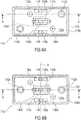
- Figs. 6 (a) and 6 (b)each show a plan view of the Wippschaltvoroplasty 116 according to Fig. 4 and Fig. 5 , wherein the illustrations differ only with regard to the arrangement of the position elements 142a and 142b and their brackets.
- the position elements 142a and 142bare offset with respect to the longitudinal axis of the rocker switch device 116
- FIG Fig. 6 (b)the position elements 142a and 142b are arranged along the longitudinal axis (see the line BB) of the rocker switch device 116.
- the upper housing part 128acomprises the two receptacles 138a and 138b, and the Soumwandung 128b is recessed in the region of these recordings.
- the receptacles 138a and 138bserve to receive locking elements, which are each arranged on a web, which in turn is arranged on a side wall of the actuating element 126, as will be explained in more detail later.
- the actuator 126is rotatably and releasably attached to the upper housing part 128a.
- the movable, mechanical restoring devicewhich has the already mentioned above, rotatably mounted wheel 140a, which engages in a disposed within the actuator 126 corresponding receptacle, as will be explained later, so that the actuator 126 in non-actuated state is held in a middle position or neutral position.
- the rotatably mounted wheel 140ais releasably secured to the connector 140b, which in turn is vertically movably disposed within the bracket 140d.
- Fig. 7shows a sectional view of in Fig. 6 (a) illustrated rocker switch device 116 along the line AA.
- the front plate 124 and a lower housing part 128cshows the Fig. 7 the front plate 124 and a lower housing part 128c.
- the upper housing part 128ais detachable on the lower housing part 128c by means of the screw 136a fastened, so that in case of repair, the upper housing part 128a can be easily replaced without the usually higher-quality sensor module must be replaced.
- the screw 136aengages through an opening in the bottom 128d of the housing top 128a and through a corresponding opening in the front plate 124 and is held in the housing bottom 128c by a threaded bolt 144.
- the actuator 126includes a land 146 that is secured to a sidewall or an inner wall of the actuator 126 and that extends from a midway position along the length direction of the rocker switch 116 toward the housing top 128a.
- a latching element 148is arranged, which engages with the recess 138a, so that the actuating element 126 via the web 146, the locking element 148 and the receptacle 138a is movably and detachably attached to the upper housing part 128a (see also Fig. 6 (a) and Fig. 6 (b) ).
- the actuating element 126is arranged at such a distance from the upper housing part 128a that the actuating element 128a is moved to the left or to the right (see arrow 150 in FIG Fig. 7 ) can be moved, as will be explained later.
- the locking device for fasteningmay also be provided to connect this via a releasable screw with the upper housing part 128a.
- Fig. 7further shows a receptacle 152b formed in the actuator 128 and in which the magnetic field generating position element 142b is disposed. A corresponding, in Fig. 7 not shown for the other position element 142a is also provided.
- Fig. 7further shows that below the magnetic position element 142b, an opening 154b is arranged in the housing upper part 128a, into which the position element 142b moves during a movement of the actuating element 126. Further, located below the position member 142b disposed in the lower housing part 128c Sensor element 156b, which detects the magnetic field or magnetic field changes of the position element 142b. The sensor element 156b is arranged substantially opposite the position element 142b in order to detect a position and / or a movement of the actuating element 126 on the basis of the magnetic field of the position element 142b.
- the sensor element 156bis a non-contact sensor, for example a Hall effect sensor, an inductive sensor, a capacitive sensor or a magnetoresistive sensor.
- the lower housing part 128cis designed to be watertight and / or air-tight at least in the region of the sensor element 156b, for example by filling with an electrically non-conductive potting compound.
- the front plate 124preferably consists at least in this subregion of a non-magnetic material, for example a printed circuit board and a front foil adhered thereto.
- Fig. 8shows a sectional view of in Fig. 6 (b) shown rocker switch 116 along the line BB in Fig. 6 (b) . Based on Fig. 8 the structure of the return device is explained in detail. Further shows Fig. 8 an embodiment in which the two position elements are arranged along a common longitudinal axis, and in addition to Fig. 7 For example, the position element 142a and the associated sensor element 156a in the housing lower part 128c are shown, as well as the additional opening 154a in the bottom 128d of the housing upper part 128b and the additional holder 152a in the actuation element 126.
- Fig. 8Furthermore, the restoring device is shown, which has the rotatably mounted wheel 140a and the vertically displaceable in the holder 140d arranged connecting piece 140b.
- Fig. 8further shows the spring element 140e, which in the in Fig. 8 shown embodiment is disposed within a recess of the connecting piece 140b, wherein a housing upper part 128a adjacent end of the spring element 140e rests on the bottom 128d of the housing upper part 128a.
- the soumwandung 128b, the bottom 128d of the upper housing part 128b and the holder 140dare integrally formed.
- the return mechanismfurther comprises a resetting element receptacle 140f arranged in the actuating element 128, in which the restoring element 140a, the rotatably mounted wheel, is accommodated.
- the receptacle 140fincludes a recess 140g within which the wheel 140a in the in Fig. 8 shown neutral position or center position is arranged.
- the recess 140gincludes side walls 140a extending to projections 140i disposed on both sides of the recess 140g. Tilting the actuator 126 to the left or to the right causes movement of the wheel 140a out of the recess 140g along one of the side surfaces 140h toward one of the projections 140i, as described below with reference to FIGS Figs. 9 (a) and 9 (b) is explained in more detail.
- Fig. 9 (a)shows a tilt of the actuator 126 to the right, for example, by applying a pressure on the control panel 134b (see Fig. 4 and Fig. 5 ), as it is in Fig. 9 (a) schematically indicated by the arrow 158a.
- FIG. 12shows tilting of the actuator 126 to the left, for example, by actuation of the actuator 126 by applying pressure to the control panel 134a (see FIG Fig. 4 and Fig. 5 ), as shown schematically by the arrow 158b.
- the exercise of a force on the corresponding controlscauses tilting of the actuator 126, as shown in the Figs.
- 9 (a) and 9 (b)is represented by the deflected from the vertical position of the web 146, and the actuator 126 rotates about the fixed by the locking elements 148 axis of rotation to the right or to the left, so that the distance between the position elements 142a, 142b to the sensor elements 156a, 156b increases or reduced.
- Figs. 9 (a) and 9 (b)It can also be seen that the tilting of the operating member 126 causes the wheel 140a of the return mechanism 140 to move along the side surface 140h toward the projection 140i but not reach or exceed it. This movement is made possible because the connecting piece 140b is arranged to be vertically displaceable within the holder 140d. Tilting the actuator 126, which is connected to the housing via the web 146, causes movement of the connector 140b against the spring force of the spring 140e down toward the housing within the bracket 140d, thereby causing movement of the wheel 140 along the side surface 140h the recess 140g in the direction of the projection 140i is made possible.
- the dimensioning of the return mechanism 140is selected such that the projection is not exceeded, but the wheel 140a remains in the maximum deflected position of the actuating element 126 in the region of the side surface 140h.
- the return mechanismcauses the wheel 140a to recede into the recess along the side surface 140h due to the spring force of the compressed spring 140e 140g moved back to the original, neutral center position according to Fig. 8 take.
- the positioning elements 142a and 142b within the actuating element 126have a maximum distance to the axis of rotation by the position elements 142a, 142b, or their holders in the actuator as far as possible at the opposite ends along the longitudinal direction BB (see Fig. 6 (b) ) to be ordered. It is preferable to at least ensure that the distance of the position elements 142a, 142b from the axis of rotation is greater than the distance to the edge of the actuating element.
- This embodimentis advantageous since a change in the distance between the position element 142a, 142b and the opposing sensor element 156a, 156b is as large as possible during a movement of the actuating element 126, so that a safe switching state of the Wippschaltvortechnisch 116 is detected.
- the position elements 142a, 142b and the two sensor elements 156a and 156bare arranged such that two different and mutually independent electrical signal values are present at the output of the sensor elements, so that the control and operating unit according to the invention is particularly suitable for safety-relevant applications in the field of mobile work machines or construction machines is.
- the distance of the position elements 142a, 142b from the respective opposite sensor elements 156a, 156b in the non-actuated state of the Wippschaltvorraum 116are essentially the same.
- the signal values at the output of the sensor elements 156a and 156b in the non-actuated state of the actuating element 126are essentially the same.
- the distance between the position elements 142a, 142b and the respectively opposite sensor elements 156a, 156bincreases or decreases with a movement of the actuating element 126 depending on the direction of movement.
- the difference in the signal valuesalso increases or decreases, depending on the direction in which the actuating element 126 is moved.
- the difference in signal valuesis proportional to the position of the actuator 126.
- the lower housing part 128cis made watertight and / or air-tight at least in the region of the sensor elements 156a, 156b, for example by filling this region of the housing with an electrically non-conductive potting compound.
- Such an encapsulated embodimentprotects the lower housing part 128c the therein sensor elements 158a, 158b from environmental influences, such as rain or dust.
- the lower housing part 128ccan be glued to the underside of the front plate 124, screwed on and fastened by means of a latching device, wherein this mounting option is not shown in the figures.
- the front panel in this areais preferably made of a non-magnetic material, such as a printed circuit board and a front sheet placed thereon.
- the control and operating unit according to the invention or its rocker switch device according to such an embodimentis less prone to interference with external magnetic fields or other electrical or electromagnetic interference.
- a disturbance acting externally on the rocker switching device 116is superimposed on the magnetic fields of the position elements or of the permanent magnets 142a, 142b and accordingly has no or only a slight influence on the values measured by the two sensor elements. This increases the suitability of the control and operating unit according to the invention for safety-relevant applications in the field of mobile work machines or construction machinery.
- the staggered arrangement of the position and sensor elementshas the advantage that, for example, the fastening screws 136a, 136b can be arranged so that they have the greatest possible distance from the position and sensor elements, and therefore no or only a small influence on the magnetic field of the position elements have, whereby the susceptibility of the Wippschaltvoroplasty can be further reduced.
- the structure of the Wippschaltvoriques 116 of the control and operating unit 10 according to the inventionenables a safe and redundant evaluation of a switching operation, so that this Wippschaltvortechnisch in safety-related applications, for example in aerial work platforms, can be used easily.
- a housingcomprising an upper housing part 128a and a lower housing part 128c.
- the present inventionis not limited to such a configuration. According to further embodiments, no lower housing part is present, so that the housing comprises only the upper housing part.
- the sensor elementsare e.g. mounted on the underside of a circuit board, which may also serve as the front panel described above. In other words, the circuit board can be considered as a lower housing part or form the lower housing part.
- aspectshave been described in the context of a device, it will be understood that these aspects also constitute a description of the corresponding method, so that a block or a component of a device is also to be understood as a corresponding method step or as a feature of a method step. Similarly, aspects described in connection with or as a method step also represent a description of a corresponding block or detail or feature of a corresponding device.
Landscapes
- Forklifts And Lifting Vehicles (AREA)
Abstract
Translated fromGermanDescription
Translated fromGermanDie vorliegende Erfindung bezieht sich auf das Gebiet von Steuer- und Bedieneinheiten an Hubarbeitsbühnen, an mobilen Arbeitsmaschinen oder an Baumaschinen mit mindestens einer Wippschaltvorrichtung sowie auf eine Hubarbeitsbühne, eine mobile Arbeitsmaschine und eine Baumaschine mit einer derartigen Steuer- und Bedieneinheit.The present invention relates to the field of control and operating units on aerial work platforms, on mobile work machines or on construction machines with at least one rocker switch device and on an aerial work platform, a mobile work machine and a construction machine with such a control and operating unit.
Steuer- und Bedieneinheiten werden beispielsweise an Hubarbeitsbühnen zum Verfahren eines Arbeitskorbes oder an Baumaschinen zum Verstellen eines Arbeitswerkzeuges verwendet. Dabei sind die Steuer- und Bedieneinheiten in der Regel widrigsten Umweltbedingungen, wie beispielsweise Regen oder Staub sowie extremen Temperaturen, ausgesetzt. Derartige Steuer- und Bedieneinheiten umfassen verschiedene Module, beispielsweise eine Tastatur, einen Joystick und/oder eine Anzeige. Im Tastaturmodul können verschiedene Arten von Schaltern bzw. Schaltvorrichtungen eingesetzt werden, beispielsweise auch Kipp- bzw. Wippschalter oder Wipptaster, die allgemein auch als "Rocker-Switches" bekannt sind.Control and operating units are used for example on aerial work platforms for moving a working basket or on construction machines for adjusting a working tool. The control and operating units are usually the most adverse environmental conditions, such as rain or dust and extreme temperatures exposed. Such control and operating units include various modules, such as a keyboard, a joystick and / or a display. In the keyboard module, various types of switches or switching devices can be used, for example, tilt or rocker switch or rocker switch, which are also commonly known as "rocker switches".
Im Stand der Technik sind verschiedene Ausgestaltungen von "Rocker-Switches" für Steuer- und Bedieneinheiten an mobilen Arbeitsmaschinen oder Baumaschinen bekannt, welche im Wesentlichen aus einem einzigen kompakten Schaltermodul bestehen. Dieser Aufbau ist nachteilhaft, da im Reparaturfall der komplette Schalter ausgebaut werden muss. Als Schaltelemente werden üblicherweise Mikroschalter oder ähnliche mechanische Schaltelemente verwendet, welche einem hohen Verschleiß unterliegen und somit im Hinblick auf ihre Lebenserwartung nachteilhaft sind. Ferner sind in dem Bereich von Steuer- und Bedieneinheiten an Maschinen auch Rocker-Switches mit Hall-Sensoren bekannt. Die
Rocker-Switches mit Hall-Sensoren sind auch in anderen Einsatzbereichen bekannt, so offenbart beispielsweise die
Der Nachteil bei den aus dem Stand der Technik bekannten Wippschaltvorrichtungen ist darin zu sehen, dass ein definierter und sicherer Schaltzustand nur anhand eines Sensors erkannt werden kann. Auch bei der aus der
Ausgehend von diesem Stand der Technik liegt der vorliegenden Erfindung die Aufgabe zugrunde, eine Steuer- und Bedieneinheit mit einer Wippschaltvorrichtung für ein Hubarbeitsbühne, eine mobile Arbeitsmaschine oder eine Baumaschine zu schaffen, welche für sicherheitsrelevante Anwendungen geeignet ist, welche weniger störanfällig ist, und welche im Reparaturfall einfach auszuwechseln ist.Based on this prior art, the present invention seeks to provide a control and operating unit with a Wippschaltvorrichtung for a working platform, a mobile work machine or a construction machine, which is suitable for security applications, which is less susceptible to interference, and which in Repair case is easy to replace.
Diese Aufgabe wird durch den Gegenstand der unabhängigen Patentansprüche gelöst, und bevorzugte Ausführungen der Erfindung sind in den Unteransprüchen definiert.This object is solved by the subject-matter of the independent claims, and preferred embodiments of the invention are defined in the sub-claims.
Die vorliegende Erfindung schafft eine Steuer- und Bedieneinheit für eine Hubarbeitsbühne, eine mobile Arbeitsmaschine oder eine Baumaschine, mit zumindest einer Wippschaltvorrichtung, die ein Gehäuse und ein an dem Gehäuse lösbar befestigtes Betätigungselement umfasst, wobei das Betätigungselement in Bezug zu dem Gehäuse um mindestens eine Drehachse bewegbar ist und zumindest zwei Positionselemente umfasst, und wobei an oder in dem Gehäuse zumindest zwei den Positionselementen gegenüberliegende Sensorelemente angeordnet sind, um eine Position und/oder eine Bewegung des Betätigungselements zu detektieren.The present invention provides a control and operating unit for an aerial work platform, a mobile work machine or a construction machine, comprising at least one rocker switch device comprising a housing and a releasably secured to the housing actuator, wherein the actuating element with respect to the housing about at least one axis of rotation is movable and comprises at least two position elements, and wherein at least two of the position elements opposite sensor elements are arranged on or in the housing to detect a position and / or movement of the actuating element.
Gegenüber dem oben erwähnten Stand der Technik ist die erfindungsgemäße Steuerund Bedieneinheit vorteilhaft, da zwei Positionselemente innerhalb des Betätigungselements vorgesehen sind, denen zwei Sensorelemente zugeordnet sind, die in dem Gehäuse angeordnet sind, sodass bei einem Schaltvorgang am Ausgang der Sensorelemente unterschiedliche und voneinander unabhängige elektrische Signalwerte vorliegen, auf deren Grundlage eine Position bzw. eine Bewegung des Betätigungselements sicher detektiert werden kann. Ferner ermöglicht die Verwendung der zwei Positionselemente und der zwei Sensorelemente eine Auswertung der unabhängigen Sensorsignale, wodurch beispielsweise die für Sicherheitsanwendungen wichtige sichere und redundante Auswertung eines Schaltvorgangs gewährleistet werden kann. Ein weiterer Vorteil der erfindungsgemäßen Vorrichtung besteht darin, dass Temperaturänderungen nicht oder nur sehr gering auf die Wippschaltvorrichtung Einfluss haben, da diese gleichmäßig auf beide Sensorelemente einwirken, und demgemäß eine gleichmäßige Auswirkung auf die gemessenen Werte haben.Compared to the above-mentioned prior art, the control and operating unit according to the invention is advantageous because two position elements are provided within the actuating element, which are associated with two sensor elements which are arranged in the housing, so that in a switching operation at the output of the sensor elements different and independent electrical signal values are present, on the basis of which a position or a movement of the actuating element can be reliably detected. Furthermore, the use of the two position elements and the two sensor elements allows an evaluation of the independent sensor signals, whereby, for example, the important for security applications safe and redundant evaluation of a switching operation can be ensured. A further advantage of the device according to the invention is that temperature changes do not or only very slightly influence the rocker switch device, since these act uniformly on both sensor elements and accordingly have a uniform effect on the measured values.
Gemäß Ausführungsbeispielen sind die Sensorelemente und die Positionselemente derart angeordnet, dass die Sensorelemente und die Positionselemente in jeder Position des Betätigungselements voneinander beabstandet sind.According to embodiments, the sensor elements and the position elements are arranged such that the sensor elements and the position elements are spaced apart in each position of the actuating element.
Gemäß Ausführungsbeispielen umfasst die Steuer- und Bedieneinheit einen Rückstellmechanismus zur Bewegung des Betätigungselements aus einer betätigten Position in eine neutrale Position. Der Rückstellmechanismus kann gemäß Ausführungsbeispielen im Bereich der Drehachse des Betätigungselements angeordnet sein. Gemäß Ausführungsbeispielen umfasst der Rückstellmechanismus ein Rückstellelement, beispielsweise in Form eines Rades oder einer Welle, das an dem Gehäuse angeordnet ist, und eine Rückstellelementaufnahme in dem Betätigungselement, wobei das Rückstellelement ausgebildet ist, um das Betätigungselement in die neutrale Position zu bewegen. Gemäß Ausführungsbeispielen kann vorgesehen sein, dass die Rückstellelementaufnahme eine Vertiefung aufweist, in der das Rückstellelement in der neutralen Position des Betätigungselements angeordnet ist, wobei das Rückstellelement bei einer Betätigung des Betätigungselements aus der Vertiefung bewegbar ist, und wobei das Rückstellelement in dem Gehäuse gelagert ist, um an einer betätigten Position des Betätigungselements eine Kraft in Richtung des Betätigungselements zu bewirken, um das Betätigungselement in die Vertiefung zurückzubewegen. Gemäß Ausführungsbeispielen kann vorgesehen sein, dass das Rückstellelement federnd in dem Gehäuse gelagert ist, um bei einer Bewegung aus der Vertiefung in Richtung des Betätigungselements vorgespannt zu sein. Das Rückstellelement kann gemäß Ausführungsbeispielen mittig zwischen den zwei Positionselementen in dem Gehäuse angeordnet sein und die Rückstellelementaufnahme ist in dem Betätigungselement gegenüberliegend zu dem Rückstellelement angeordnet.According to embodiments, the control and operating unit comprises a return mechanism for moving the actuating member from an actuated position to a neutral position. The return mechanism can according to embodiments in the area be arranged the axis of rotation of the actuating element. According to embodiments, the return mechanism comprises a return element, for example in the form of a wheel or a shaft, which is arranged on the housing, and a restoring element receptacle in the actuating element, wherein the restoring element is designed to move the actuating element in the neutral position. According to embodiments, it may be provided that the restoring element receptacle has a recess in which the restoring element is arranged in the neutral position of the actuating element, wherein the restoring element is movable upon actuation of the actuating element from the recess, and wherein the restoring element is mounted in the housing, to cause a force in the direction of the actuating element at an actuated position of the actuating element to move the actuating element back into the recess. According to embodiments, it may be provided that the return element is resiliently mounted in the housing in order to be biased in a movement of the recess in the direction of the actuating element. The restoring element can be arranged in the middle between the two position elements in the housing according to embodiments, and the restoring element receiving is arranged in the actuating element opposite to the restoring element.
Diese Ausgestaltung des Rückstellmechanismus ist vorteilhaft, da hierdurch sichergestellt wird, dass bei einer Nicht-Betätigung des Betätigungselements des Wippschalters bzw. der Wippschaltvorrichtung das Betätigungselement in seine neutrale Position zurückbewegt wird, in der eine Nicht-Betätigung aufgrund der ausgelesenen Sensorsignale erfasst wird. Somit wird bei Loslassen des Wippschalters jegliche Bewegung oder andersartige Betätigung eines Elements der Maschine, beispielsweise eines Arbeitskorbes der Hubarbeitsbühne oder eines Arbeitswerkzeuges einer Baumaschine beendet, wie es insbesondere bei sicherheitsrelevanten Anwendungen erforderlich ist. Ein weiterer Vorteil der erfindungsgemäßen Ausgestaltung des Rückstellmechanismus besteht darin, dass hier eine Konstruktion bereitgestellt wird, die das Zurückführen des Betätigungselements in die neutrale Position unterstützt, insbesondere wird die Rückstellung durch ein einzelnes Element, nämlich das Rückstellelement, bewirkt, welches federnd gelagert sein kann. Der Einsatz mehrerer, gleichwertiger Bauelemente, die auf das Betätigungselement zum Zurückstellen desselben aus unterschiedlichen betätigten Positionen in die neutrale Position einwirken, wird vermieden, und damit die Notwendigkeit mehrere gleiche Bauelemente im Hinblick auf ihre Rückstellkraft zur Sicherstellung der neutralen Position vorzusehen. Dies vermeidet Probleme im Hinblick auf eine unterschiedliche Alterung unterschiedlicher Elemente über die Zeit, die zu einer fehlerhaften Ausrichtung des Betätigungselements bezüglich der ursprünglich definierten neutralen Position führen können, die dann nicht mehr sicher eingenommen wird, wie es im Zusammenhang mit sicherheitsrelevanten Anwendungen aber erforderlich ist. Solche Nachteile werden durch die erfindungsgemäße Ausgestaltung gemäß Ausführungsbeispielen vermieden, da der zentrale Rückstellmechanismus ein Rückstellelement in Form eines Rades aufweist, welches in einer Vertiefung aufgenommen wird. Das Rad kann sich bei einer Betätigung des Schalters aus einer tiefsten Stelle der Ausnehmung in Richtung eines angehobenen Endes des Schalters bewegen, und wird nach dem Schaltvorgang durch eine Federkraft wieder in die Vertiefung zurückgezwungen, sodass eine zuverlässige Bewegung des Schalters in die neutrale Position sichergestellt ist.This embodiment of the return mechanism is advantageous because it is ensured that when a non-actuation of the actuating element of the rocker switch or the Wippschaltvorrichtung the actuator is moved back to its neutral position in which a non-operation is detected due to the read sensor signals. Thus, upon release of the rocker switch, any movement or other type of actuation of an element of the machine, such as a working basket of the aerial work platform or a work implement of a construction machine is terminated, as is required in particular for safety-relevant applications. Another advantage of the inventive design of the return mechanism is that here a construction is provided which supports the return of the actuating element in the neutral position, in particular the provision is effected by a single element, namely the return element, which can be resiliently mounted. The use of a plurality of equivalent components acting on the actuator to return it from different actuated positions to the neutral position is avoided, and thus the need to provide a plurality of identical components with respect to their restoring force to ensure the neutral position. This avoids problems with respect to a different aging of different elements over time, resulting in a misalignment of the actuator with respect can lead to the originally defined neutral position, which is then no longer safely taken, as is necessary in connection with security-relevant applications. Such disadvantages are avoided by the inventive embodiment according to embodiments, since the central return mechanism has a restoring element in the form of a wheel, which is received in a recess. The wheel can move from a lowest point of the recess toward a raised end of the switch upon actuation of the switch, and is forced back into the recess after the switching operation by a spring force, so that a reliable movement of the switch is ensured in the neutral position ,
Gemäß Ausführungsbeispielen sind die Positionselemente innerhalb des Betätigungselements so angeordnet, dass ein Abstand eines Positionselements zu der Drehachse größer ist als zu einem Rand des Betätigungselements. Vorzugsweise sind die Positionselemente so angeordnet, dass der Abstand eines Positionselements zur Drehachse im Hinblick auf die Möglichkeit der Anordnung der Positionselemente innerhalb des Betätigungselements maximal wird.According to embodiments, the position elements are arranged within the actuating element so that a distance of a position element to the axis of rotation is greater than to an edge of the actuating element. Preferably, the position elements are arranged so that the distance of a position element to the axis of rotation is maximum in view of the possibility of arranging the position elements within the actuating element.
Diese Ausgestaltung ist vorteilhaft, da hierdurch bei einer Betätigung des Betätigungselements ein Abstand zwischen einem der Positionselemente und dem Sensorelement einen großen Wert annimmt, wohingegen ein Abstand zwischen dem anderen Sensorelement und dem anderen Positionselement gering wird, sodass die durch die Sensoren erfassten Signale sicher zu unterscheiden sind.This embodiment is advantageous since, upon actuation of the actuating element, a distance between one of the position elements and the sensor element assumes a large value, whereas a distance between the other sensor element and the other position element becomes small, so that the signals detected by the sensors can be reliably distinguished are.
Gemäß Ausführungsbeispielen sind die Positionselemente derart angeordnet, dass sich ein Abstand zwischen den Positionselementen und den jeweils gegenüberliegenden Sensorelementen bei einer Bewegung des Betätigungselements je nach Bewegungsrichtung vergrößert oder verkleinert.According to embodiments, the position elements are arranged such that increases a distance between the position elements and the respective opposite sensor elements in a movement of the actuating element depending on the direction of movement or reduced.
Diese Ausgestaltung ist vorteilhaft, da hierdurch die Abstände zwischen den Sensorelementen und den Positionselementen unterschiedlich sind, und somit eine sichere Unterscheidung der erfassten Signale ermöglicht wird.This refinement is advantageous, since in this way the distances between the sensor elements and the position elements are different, and thus a reliable differentiation of the detected signals is made possible.
Gemäß Ausführungsbeispielen vergrößert oder verkleinert sich die Differenz der Signalwerte der Sensorelemente bei einer Bewegung des Betätigungselements je nach Bewegungsrichtung, wobei es gemäß Ausführungsbeispielen ausreichend ist, dass die Differenz der Signalwerte der Sensorelemente im Wesentlichen proportional zur Position der Betätigungselemente ist. Gemäß Ausführungsbeispielen ist ferner vorgesehen, dass die Signalwerte der Sensorelemente im nicht-betätigten Zustand des Betätigungselements annähernd gleich sind.According to exemplary embodiments, the difference between the signal values of the sensor elements increases or decreases in the case of a movement of the actuating element depending on the direction of movement, it being sufficient according to embodiments that the difference the signal values of the sensor elements is substantially proportional to the position of the actuators. According to embodiments, it is further provided that the signal values of the sensor elements in the non-actuated state of the actuating element are approximately equal.
Diese Ausgestaltung ist vorteilhaft, da hierdurch eine sichere Erfassung einer Bewegungsrichtung beim Schalten gewährleistet wird.This embodiment is advantageous, since this ensures a reliable detection of a direction of movement when switching.
Gemäß Ausführungsbeispielen umfassen die Positionselemente Magnetfeld-erzeugende Elemente, z.B. Dauermagnete, deren Pole vorzugsweise in Bezug zu den Sensorelementen gleich ausgerichtet sind.According to embodiments, the position elements comprise magnetic field generating elements, e.g. Permanent magnets whose poles are preferably aligned with respect to the sensor elements are the same.
Diese Ausgestaltung ist vorteilhaft, da hierdurch die Steuer- und Bedieneinheit bzw. deren Wippschaltvorrichtung weniger störanfällig gegenüber äußeren Magnetfeldern oder anderen elektrischen bzw. elektromagnetischen Störungen ist. Eine von außen auf die Wippschaltvorrichtung einwirkende Störung wird mit Magnetfeldern der Dauermagnete überlagert und hat demgemäß keinen bzw. nur geringfügigen Einfluss auf die von den Sensorsignalen gemessenen Werte, sodass die erfindungsgemäße Steuer- und Bedieneinheit insbesondere für sicherheitsrelevante Anwendungen im Bereich mobiler Arbeitsmaschinen, beispielsweise Hubarbeitsbühnen, oder im Bereich von Baumaschinen geeignet ist.This refinement is advantageous since the control and operating unit or its rocker switching device is less susceptible to interference from external magnetic fields or other electrical or electromagnetic interference. A disturbance acting externally on the rocker switching device is superimposed with magnetic fields of the permanent magnets and accordingly has no or only slight influence on the values measured by the sensor signals, so that the control and operating unit according to the invention is particularly suitable for safety-relevant applications in the field of mobile work machines, for example aerial work platforms. or in the field of construction machinery is suitable.
Ein wesentlicher Aspekt dieser Ausführungsform besteht darin, dass erstmals ein Wippschalter geschaffen wird, der aufgrund seines Aufbaus eine Fremdmagnetfelderkennung und -handhabung ermöglicht. Im Stand der Technik bekannte Wippschalter, z.B. Hall-Wippschalter, stellen keine solche Funktionalität bereit. Die erfindungsgemäße Fremdmagnetfelderkennung und -handhabung verbessert die Sicherheit, indem unerwünschte Schaltvorgänge verhindert werden bzw. Fehlerzustände erkannt werden. So kommt es in der Praxis regelmäßig zu Situationen, in denen ein Schalter unbeabsichtigt einem Magnetfeld ausgesetzt ist, welches bei bekannten Schaltern zu einer Fehlfunktion bzw. zu einem unbeabsichtigten Auslösen des Schalters führen kann. Beispielsweise kann eine an einer Magnethalterung angeordnete Beleuchtungsvorrichtung (Lampe) durch einen Bediener von einem Maschinenrahmen abgenommen und auf das Bedienpult gelegt werden. Hierdurch wird durch den erfindungsgemäßen Wippschalter kein Schaltvorgang/Maschinenbewegung ausgelöst, da das Störfeld auf beide Sensoren im Wesentlichen gleich wirkt.An essential aspect of this embodiment is that for the first time a rocker switch is provided, which allows due to its structure, a Fremdmagnetfeldkennung and handling. Rocker switches known in the art, eg, Hall rocker switches, do not provide such functionality. The external magnetic field detection and handling according to the invention improves the safety by preventing undesired switching operations or detecting fault conditions. So it comes in practice regularly situations in which a switch is unintentionally exposed to a magnetic field, which can lead to known switches to a malfunction or inadvertent release of the switch. For example, an illumination device (lamp) arranged on a magnetic mount can be removed by an operator from a machine frame and placed on the control panel. As a result, no switching process / machine movement is triggered by the rocker switch according to the invention, since the interference field acts essentially the same on both sensors.
Auch Fehlerfälle bzw. Fehlerzustände können erkannt werden, z.B. der Ausfall eines Sensorelementes oder eines Magneten, der sich z.B. gelöst hat, aber auch eine Demontage des gesamten Betätigungsfeldes. In einer solchen Situation sind z.B. die erfassten Ausgangssignale in der Ruheposition unterschiedlich oder liegen unterhalb eines Schwellwertes, woraus auf einen Fehlerzustand geschlossen werden kann. Aufgrund der Möglichkeit, solche Fehlerfälle zu erkennen, erhöht sich die Sicherheit des erfindungsgemäßen Wippschalters gegenüber herkömmlichen Wippschaltern.Error cases can also be detected, e.g. the failure of a sensor element or a magnet, e.g. has solved, but also a disassembly of the entire field of activity. In such a situation, e.g. the detected output signals in the rest position are different or below a threshold value, from which it can be concluded that an error condition. Due to the ability to detect such errors, increases the safety of the rocker switch according to the invention over conventional rocker switches.
Gemäß Ausführungsbeispielen umfassen die Sensorelemente berührungslose Sensoren, wie Halleffekt-Sensoren, induktive, kapazitive oder magnetoresistive Sensoren.According to embodiments, the sensor elements include non-contact sensors, such as Hall effect sensors, inductive, capacitive or magnetoresistive sensors.
Gemäß Ausführungsbeispielen umfasst das Gehäuse und/oder das Betätigungselement zumindest teilweise Kunststoff, Aluminium oder ein anderes nicht-magnetisches Material.According to embodiments, the housing and / or the actuator comprises at least partially plastic, aluminum or other non-magnetic material.
Diese Ausgestaltung ist vorteilhaft, da hierdurch eine zusätzliche Öffnung innerhalb einer Frontplatte, auf der das Betätigungselement montiert ist, verhindert wird, da das Magnetfeld, das durch die Positionselemente erzeugt wird, aufgrund der nicht-magnetischen Eigenschaft eines Teils des Gehäuses und/oder des Betätigungselements die Sensorelemente erreicht, wodurch diese beispielsweise abgekapselt, also getrennt von dem Betätigungselement innerhalb eines Gehäuses angeordnet sein können. Dies ermöglicht einen separaten Austausch des Betätigungselements, ohne Austausch des Sensormoduls.This embodiment is advantageous because it prevents an additional opening within a front panel on which the actuator is mounted, since the magnetic field generated by the position elements due to the non-magnetic property of a part of the housing and / or the actuating element reaches the sensor elements, whereby these, for example, encapsulated, so can be arranged separately from the actuator within a housing. This allows a separate replacement of the actuator, without replacement of the sensor module.
Gemäß Ausführungsbeispielen umfasst das Gehäuse ein Gehäuseunterteil und ein Gehäuseoberteil, wobei die Sensorelemente vorzugsweise an dem Gehäuseunterteil angeordnet sind, und das Betätigungselement vorzugsweise an dem Gehäuseoberteil angeordnet ist. Gemäß Ausführungsbeispielen kann das Gehäuseunterteil mit dem Gehäuseoberteil mittels einer oder mehrerer Schrauben oder einer Rastvorrichtung lösbar verbunden sein. Gemäß Ausführungsbeispielen kann vorgesehen sein, dass das Gehäuseunterteil zumindest im Bereich der Sensorelemente wasserdicht und/oder luftdicht ist. Gemäß Ausführungsbeispielen ist das Betätigungselement mittels einer oder mehrerer Schrauben oder einer Rastvorrichtung lösbar an dem Gehäuseoberteil befestigt.According to embodiments, the housing comprises a housing lower part and a housing upper part, wherein the sensor elements are preferably arranged on the housing lower part, and the actuating element is preferably arranged on the housing upper part. According to embodiments, the lower housing part may be releasably connected to the upper housing part by means of one or more screws or a locking device. According to embodiments it can be provided that the lower housing part is waterproof and / or airtight at least in the region of the sensor elements. According to embodiments, the actuating element is releasably secured by means of one or more screws or a locking device to the upper housing part.
Diese Ausgestaltung der erfindungsgemäßen Steuer- und Bedieneinheit ist vorteilhaft, da hierdurch das Betätigungselement und die Sensorelemente voneinander getrennt sind, sodass diese auch getrennt austauschbar sind. Insbesondere ist es vorteilhaft, dass die Sensorelemente innerhalb des Gehäuseunterteils angeordnet sind, und zwar so, dass diese vor Umgebungseinflüssen geschützt sind, sodass ein Austausch eines Sensormoduls weniger häufig erforderlich ist. Aufgrund der Umgebungsbedingungen ist lediglich ein häufigerer Austausch des Betätigungselements mit den kostengünstigen Elementen in Form der magnetischen Positionsbestimmungselemente, beispielsweise in Form von Dauermagneten erforderlich.This embodiment of the control and operating unit according to the invention is advantageous because in this way the actuating element and the sensor elements are separated from each other, so that they are also exchanged separately. In particular, it is advantageous that the sensor elements are arranged within the housing lower part, in such a way that These are protected from environmental influences, so that a replacement of a sensor module is required less frequently. Due to the environmental conditions, only a more frequent replacement of the actuating element with the cost-effective elements in the form of the magnetic position-determining elements, for example in the form of permanent magnets is required.
Gemäß Ausführungsbeispielen ist das Gehäuse lösbar an der Steuer- und Bedieneinheit befestigt.According to embodiments, the housing is releasably attached to the control and operating unit.
Diese Ausgestaltung ist vorteilhaft, da hierdurch auf einfache Art und Weise im Bedarfsfall auch ein Austausch des Sensormoduls ermöglicht wird.This refinement is advantageous, since this also makes it possible to exchange the sensor module in a simple manner if required.
Gemäß Ausführungsbeispielen der vorliegenden Erfindung wird ferner eine Hubarbeitsbühne, eine mobile Arbeitsmaschine oder eine Baumaschine mit der erfindungsgemäßen Steuer- und Bedieneinheit bereitgestellt.According to embodiments of the present invention, an aerial work platform, a mobile work machine or a construction machine with the control and operating unit according to the invention is further provided.
Nachfolgend werden unter Bezugnahme auf die beiliegenden Zeichnungen bevorzugte Ausführungsbeispiele der vorliegenden Erfindung näher erläutert. Es zeigen:
- Fig. 1
- die Darstellung einer Hubarbeitsbühne mit einer Steuer- und Bedieneinheit, welche den erfindungsgemäßen Handsteuergeber aufweist;
- Fig. 2
- eine detailliertere Darstellung der in
Fig. 1 dargestellten Steuer- und Bedieneinheit; - Fig. 3
- einen Ausschnitt einer Steuer- und Bedieneinheit gemäß einem Ausführungsbeispiel der Erfindung, ähnlich der Steuer- und Bedieneinheit aus
Fig. 2 ; - Fig. 4
- ein Ausführungsbeispiel eines Wippschalters der erfindungsgemäßen Steuer- und Bedieneinheit für eine mobile Arbeitsmaschine oder eine Baumaschine;
- Fig. 5
- eine Explosionsdarstellung des in
Fig. 4 gezeigten Wippschalters zur Darstellung dessen Innenaufbaus; - Fig. 6
- Draufsichtdarstellungen der Wippschaltvorrichtung gemäß
Fig. 4 undFig. 5 , wobei inFig. 6(a) die Positionselemente in Bezug zur Längsachse der Wippschaltvorrichtung versetzt angeordnet, und wobei inFig. 6(b) die Positionselemente entlang der Längsachse der Wippschaltvorrichtung angeordnet sind; - Fig. 7
- eine Schnittdarstellung der in
Fig. 6(a) dargestellten Wippschaltvorrichtung entlang der Linie A-A; - Fig. 8
- eine Schnittdarstellung der in
Fig. 6(b) dargestellten Wippschaltvorrichtung entlang der Linie B-B inFig. 6(b) ; und - Fig. 9
- eine Verkippung des Betätigungselements, wobei
Fig. 9(a) eine Verkippung des Betätigungselements nach rechts zeigt, und wobeiFig. 9(b) eine Verkippung des Betätigungselements nach links zeigt.
- Fig. 1
- the representation of an aerial work platform with a control and operating unit, which has the hand control transmitter according to the invention;
- Fig. 2
- a more detailed account of in
Fig. 1 illustrated control and operating unit; - Fig. 3
- a section of a control and operating unit according to an embodiment of the invention, similar to the control and operating unit
Fig. 2 ; - Fig. 4
- an embodiment of a rocker switch of the control and operating unit according to the invention for a mobile work machine or a construction machine;
- Fig. 5
- an exploded view of the in
Fig. 4 Rocker switch shown to illustrate its internal structure; - Fig. 6
- Plan view of the rocker switch according to
Fig. 4 andFig. 5 , where inFig. 6 (a) the position elements are offset relative to the longitudinal axis of the Wippschaltvorrichtung, and wherein inFig. 6 (b) the positioning elements are arranged along the longitudinal axis of the Wippschaltvorrichtung; - Fig. 7
- a sectional view of in
Fig. 6 (a) illustrated rocker switch along the line AA; - Fig. 8
- a sectional view of in
Fig. 6 (b) illustrated rocker switch along the line BB inFig. 6 (b) ; and - Fig. 9
- a tilting of the actuating element, wherein
Fig. 9 (a) shows a tilt of the actuator to the right, and whereinFig. 9 (b) shows a tilt of the actuator to the left.
Nachfolgend werden Ausführungsbeispiele der vorliegenden Erfindung unter Bezugnahme auf die beiliegenden Zeichnungen näher erläutert, wobei in den beiliegenden Zeichnungen gleiche oder gleichwirkende Elemente mit den gleichen Bezugszeichen versehen sind.Hereinafter, embodiments of the present invention will be explained in more detail with reference to the accompanying drawings, wherein in the accompanying drawings, the same or equivalent elements are provided with the same reference numerals.
Details eines des in der
In einem mittleren Bereich des Gehäuseoberteils 128a ist eine bewegbare mechanische Rückstelleinrichtung angeordnet, die in ihrer Gesamtheit mit den Bezugszeichen 140 bezeichnet ist, die eine in
Die
Im mittleren Bereich des Gehäuseoberteils 128a findet sich die bewegbare, mechanische Rückstelleinrichtung, welche das bereits oben erwähnte, drehbar gelagerte Rad 140a aufweist, welches in eine innerhalb des Betätigungselements 126 angeordnete korrespondierende Aufnahme eingreift, wie dies später noch erläutert wird, sodass das Betätigungselement 126 im nicht-betätigten Zustand in einer Mittelposition oder Neutralposition gehalten wird. Das drehbar gelagerte Rad 140a ist lösbar an dem Verbindungsstück 140b befestigt, welches seinerseits innerhalb der Halterung 140d vertikal beweglich angeordnet ist.In the middle region of the
Anhand der
Gemäß Ausführungsbeispielen kann anstelle der Rastvorrichtung zur Befestigung des Betätigungselements 128 auch vorgesehen sein, dieses über eine lösbare Schraubverbindung mit dem Gehäuseoberteil 128a zu verbinden.According to embodiments, instead of the locking device for fastening the actuating element 128 may also be provided to connect this via a releasable screw with the
Gemäß Ausführungsbeispielen ist im Bereich der Öffnung 154b in der Frontplatte 124 keine zusätzliche Öffnung erforderlich, da die Frontplatte vorzugweise zumindest in diesem Teilbereich aus einem nicht-magnetischen Material besteht, beispielsweise einer Leiterplatte und einer darauf aufgeklebten Frontfolie.According to embodiments, no additional opening is required in the region of the
In
Wie aus
Gemäß Ausführungsbeispielen ist vorgesehen, dass die Positionselemente 142a und 142b innerhalb des Betätigungselements 126 einen maximalen Abstand zu dessen Drehachse aufweisen, indem die Positionselemente 142a, 142b, bzw. deren Halterungen im Betätigungselement soweit wie möglich an den entgegengesetzten Enden entlang der Längsrichtung B-B (siehe
Vorzugsweise ist der Abstand der Positionselemente 142a, 142b von den jeweils gegenüberliegenden Sensorelementen 156a, 156b im nicht-betätigten Zustand der Wippschaltvorrichtung 116 (siehe
Gemäß Ausführungsbeispielen ist das Gehäuseunterteil 128c zumindest im Bereich der Sensorelemente 156a, 156b wasserdicht und/oder luftdicht ausgestaltet, beispielsweise durch Füllen dieses Bereichs des Gehäuses mit einer elektrisch nicht-leitenden Vergussmasse. Eine derart gekapselte Ausführungsform schützt das Gehäuseunterteil 128c mit den darin befindlichen Sensorelementen 158a, 158b vor Umwelteinflüssen, wie beispielsweise Regen oder Staub. Gemäß Ausführungsbeispielen kann das Gehäuseunterteil 128c an der Unterseite der Frontplatte 124 angeklebt, angeschraubt und mittels einer Rastvorrichtung befestigt sein, wobei diese Befestigungsmöglichkeit in den Figuren nicht dargestellt sind.According to exemplary embodiments, the
Im Bereich der Öffnungen 154a, 154b ist in der Frontplatte 124 keine zusätzliche Öffnung notwendig, und die Frontplatte besteht in diesem Bereich vorzugsweise aus einem nicht-magnetischen Material, wie beispielsweise einer Leiterplatte und einer darauf aufgelegten Frontfolie.In the area of the
Gemäß Ausführungsbeispielen wird bevorzugt, die Pole der Positionselemente bzw. der Dauermagnete 142a, 142b in Bezug zu den Sensorelementen 156a, 156b gleich auszurichten, sodass entweder der Nordpol oder der Südpol der jeweiligen Dauermagnete den Sensorelementen gegenüberliegt. Diese Vorgehensweise ist vorteilhaft, da die erfindungsgemäße Steuer- und Bedieneinheit bzw. deren Wippschaltvorrichtung gemäß einer solchen Ausführungsform weniger störanfällig gegenüber äußeren Magnetfeldern oder anderen elektrischen bzw. elektromagnetischen Störungen ist. Eine von außen auf die Wippschaltvorrichtung 116 einwirkende Störung wird den Magnetfeldern der Positionselemente bzw. der Dauermagnete 142a, 142b überlagert und hat demgemäß keinen bzw. nur einen geringen Einfluss auf die von den beiden Sensorelementen gemessenen Werte. Hierdurch erhöht sich die Eignung der erfindungsgemäßen Steuer- und Bedieneinheit für sicherheitsrelevante Anwendungen im Bereich mobiler Arbeitsmaschinen oder Baumaschinen.According to embodiments, it is preferable to align the poles of the position elements or the
Bei der anhand der
Der Aufbau der Wippschaltvorrichtung 116 der erfindungsgemäßen Steuer- und Bedieneinheit 10 ermöglicht eine sichere und redundante Auswertung eines Schaltvorgangs, sodass diese Wippschaltvorrichtung in sicherheitsrelevanten Anwendungen, beispielsweise bei Hubarbeitsbühnen, ohne weiteres eingesetzt werden kann.The structure of the
Anstelle der oben beschriebenen Verwendung von zwei Positionselementen und zwei Sensorelementen kann gemäß weiteren Ausführungsbeispielen vorgesehen sein, zumindest ein weiteres Positionselement und Sensorelement vorzusehen.Instead of the above-described use of two position elements and two sensor elements, according to further embodiments, it may be provided to provide at least one further position element and sensor element.
Bei den oben beschriebenen Ausführungsbeispielen wurde auf ein Gehäuse Bezug genommen, welches ein Gehäuseoberteil 128a und ein Gehäuseunterteil 128c umfasst. Die vorliegende Erfindung ist nicht auf eine solche Ausgestaltung beschränkt. Gemäß weiteren Ausführungsbeispielen ist kein Gehäuseunterteil vorhanden, so dass das Gehäuse nur das Gehäuseoberteil umfasst. Die Sensorelemente sind z.B. auf der Unterseite einer Leiterplatte angebracht, welche auch als die oben beschriebene Frontplatte dienen kann. Mit anderen Worten kann auch die Leiterplatte als Gehäuseunterteil betrachtet werden kann bzw. das Gehäuseunterteil bilden.In the embodiments described above, reference has been made to a housing comprising an
Obwohl manche Aspekte im Zusammenhang mit einer Vorrichtung beschrieben wurden, versteht es sich, dass diese Aspekte auch eine Beschreibung des entsprechenden Verfahrens darstellen, sodass ein Block oder ein Bauelement einer Vorrichtung auch als ein entsprechender Verfahrensschritt oder als ein Merkmal eines Verfahrensschrittes zu verstehen ist. Analog dazu stellen Aspekte, die im Zusammenhang mit einem oder als ein Verfahrensschritt beschrieben wurden, auch eine Beschreibung eines entsprechenden Blocks oder Details oder Merkmals einer entsprechenden Vorrichtung dar.Although some aspects have been described in the context of a device, it will be understood that these aspects also constitute a description of the corresponding method, so that a block or a component of a device is also to be understood as a corresponding method step or as a feature of a method step. Similarly, aspects described in connection with or as a method step also represent a description of a corresponding block or detail or feature of a corresponding device.
Die oben beschriebenen Ausführungsbeispiele stellen lediglich eine Veranschaulichung der Prinzipien der vorliegenden Erfindung dar. Es versteht sich, dass Modifikationen und Variationen der hierin beschriebenen Anordnungen und Einzelheiten anderen Fachleuten einleuchten werden. Deshalb ist beabsichtigt, dass die Erfindung lediglich durch den Schutzumfang der nachstehenden Patentansprüche und nicht durch die spezifischen Einzelheiten, die anhand der Beschreibung und der Erläuterung der Ausführungsbeispiele hierin präsentiert wurden, beschränkt sei.The embodiments described above are merely illustrative of the principles of the present invention. It will be understood that modifications and variations of the arrangements and details described herein will be apparent to others of ordinary skill in the art. Therefore, it is intended that the invention be limited only by the scope of the appended claims and not by the specific details presented in the description and explanation of the embodiments herein.
- 100100
- Hubarbeitsbühneplatform
- 102102
- Chassischassis
- 104104
- Aufbauconstruction
- 106106
- Kranmechanismuscrane mechanism
- 108108
- Arbeitskorbwork basket
- 110110
- Steuer- und BedieneinheitControl and operating unit
- 110a,b110a, b
- Gehäuseteilhousing part
- 112112
- HandsteuergeberControl Transmitter
- 114114
- Bodenground
- 116a-c116a-c
- WippschalterRocker
- 118a-c118a-c
- LEDLED
- 120120
- Anzeigedisplay
- 122122
- Relingrailing
- 124124
- Frontplattefront panel
- 126126
- Betätigungselementactuator
- 128a128a
- GehäuseoberteilHousing top
- 128b128b
- Umlaufende Seitenwandung des GehäuseoberteilsAll-round side wall of the housing top
- 128c128c
- GehäuseunterteilHousing bottom
- 128d128d
- Boden des GehäuseoberteilsBottom of the housing top
- 130130
- Pfeilarrow
- 132132
- Oberfläche des BetätigungselementsSurface of the actuating element
- 134a,b134a, b
- Betätigungsfelderfields of activity
- 136a,b136a, b
- Schraubenscrew
- 138a,b138a, b
- Aufnahmeadmission
- 140140
- RückstelleinrichtungReset device
- 140a140a
- Rückstellelement/RadRestoring element / wheel
- 140b140b
- Verbindungsstückjoint
- 140c140c
- Lagerwarehouse
- 140d140d
- Halterungholder
- 140i140i
- Federelementspring element
- 140f140f
- RückstellelementaufnahmeRestoring element receptacle
- 140g140g
- Vertiefungdeepening
- 140h140h
- Seitenwand der VertiefungSide wall of the depression
- 140i140i
- Vorsprunghead Start
- 142a,b142a, b
- Positionselementeposition elements
- 144144
- Gewindebolzenthreaded bolt
- 146146
- Stegweb
- 148148
- Rastelementlocking element
- 150150
- Pfeilarrow
- 152a,b152a, b
- PositionselementaufnahmePosition element receptacle
- 154a,b154a, b
- Öffnung im GehäuseunterteilOpening in the housing base
- 156a,b156a, b
- Sensorelementesensor elements
Claims (15)
Translated fromGermandie Rückstellelementaufnahme (140f) eine Vertiefung (140g) aufweist, in der das Rückstellelement (140a) in der neutralen Position des Betätigungselements (126) angeordnet ist, wobei das Rückstellelement (140a) bei einer Betätigung des Betätigungselements (126) aus der Vertiefung (140g) bewegbar ist, und
das Rückstellelement (140a) in dem Gehäuse (128a, 128c) gelagert ist, um in der betätigten Position des Betätigungselements (126) eine Kraft in Richtung des Betätigungselements (126) zu bewirken, um das Betätigungselement (126) in die Vertiefung (140g) zurück zu bewegen.Control and operating unit according to claim 4, wherein
the restoring element receptacle (140f) has a recess (140g) in which the restoring element (140a) is in the neutral position of the actuation element (126) is arranged, wherein the return element (140 a) upon actuation of the actuating element (126) from the recess (140 g) is movable, and
the restoring element (140a) is mounted in the housing (128a, 128c) in order, in the actuated position of the actuation element (126), to exert a force in the direction of the actuation element (126) in order to move the actuation element (126) into the recess (140g). to move back.
Priority Applications (1)
| Application Number | Priority Date | Filing Date | Title |
|---|---|---|---|
| EP15172565.2AEP3107211B1 (en) | 2015-06-17 | 2015-06-17 | Control and operation unit for an elevating work platform, a mobile working machine or a construction machine |
Applications Claiming Priority (1)
| Application Number | Priority Date | Filing Date | Title |
|---|---|---|---|
| EP15172565.2AEP3107211B1 (en) | 2015-06-17 | 2015-06-17 | Control and operation unit for an elevating work platform, a mobile working machine or a construction machine |
Publications (2)
| Publication Number | Publication Date |
|---|---|
| EP3107211A1true EP3107211A1 (en) | 2016-12-21 |
| EP3107211B1 EP3107211B1 (en) | 2018-11-28 |
Family
ID=53433122
Family Applications (1)
| Application Number | Title | Priority Date | Filing Date |
|---|---|---|---|
| EP15172565.2AActiveEP3107211B1 (en) | 2015-06-17 | 2015-06-17 | Control and operation unit for an elevating work platform, a mobile working machine or a construction machine |
Country Status (1)
| Country | Link |
|---|---|
| EP (1) | EP3107211B1 (en) |
Cited By (2)
| Publication number | Priority date | Publication date | Assignee | Title |
|---|---|---|---|---|
| CN109617549A (en)* | 2018-12-26 | 2019-04-12 | 小犇(苏州)新能源科技有限公司 | A control handle and control method thereof |
| WO2020126103A1 (en)* | 2018-12-21 | 2020-06-25 | Eaton Intelligent Power Limited | Magnetic control switch |
Families Citing this family (1)
| Publication number | Priority date | Publication date | Assignee | Title |
|---|---|---|---|---|
| DE102019101611B3 (en) | 2019-01-23 | 2020-05-20 | Preh Gmbh | Operating arrangement consisting of a capacitive touchscreen or touchpad and mechanical input part with improved magnetic position detection |
Citations (7)
| Publication number | Priority date | Publication date | Assignee | Title |
|---|---|---|---|---|
| US3265826A (en)* | 1965-02-10 | 1966-08-09 | Hughes Aircraft Co | Rocker switch utilizing magnetic reeds |
| US4216458A (en) | 1978-07-03 | 1980-08-05 | Texas Instruments Incorporated | Solid state switch |
| US4868530A (en) | 1987-01-15 | 1989-09-19 | Tocksfors Verkstads Ab | Electronic switch |
| EP1167109A2 (en)* | 2000-06-30 | 2002-01-02 | AB Elektronik GmbH | Selecting and switching apparatus |
| WO2002013387A1 (en) | 2000-08-09 | 2002-02-14 | Herga Electric Limited | Switch assembly |
| WO2013159067A1 (en)* | 2012-04-20 | 2013-10-24 | Martin Bryan A | Magnetic field switches |
| US8570126B1 (en)* | 2012-09-28 | 2013-10-29 | Eaton Corporation | Contactless switch with stationary vane |
- 2015
- 2015-06-17EPEP15172565.2Apatent/EP3107211B1/enactiveActive
Patent Citations (7)
| Publication number | Priority date | Publication date | Assignee | Title |
|---|---|---|---|---|
| US3265826A (en)* | 1965-02-10 | 1966-08-09 | Hughes Aircraft Co | Rocker switch utilizing magnetic reeds |
| US4216458A (en) | 1978-07-03 | 1980-08-05 | Texas Instruments Incorporated | Solid state switch |
| US4868530A (en) | 1987-01-15 | 1989-09-19 | Tocksfors Verkstads Ab | Electronic switch |
| EP1167109A2 (en)* | 2000-06-30 | 2002-01-02 | AB Elektronik GmbH | Selecting and switching apparatus |
| WO2002013387A1 (en) | 2000-08-09 | 2002-02-14 | Herga Electric Limited | Switch assembly |
| WO2013159067A1 (en)* | 2012-04-20 | 2013-10-24 | Martin Bryan A | Magnetic field switches |
| US8570126B1 (en)* | 2012-09-28 | 2013-10-29 | Eaton Corporation | Contactless switch with stationary vane |
Cited By (3)
| Publication number | Priority date | Publication date | Assignee | Title |
|---|---|---|---|---|
| WO2020126103A1 (en)* | 2018-12-21 | 2020-06-25 | Eaton Intelligent Power Limited | Magnetic control switch |
| US11799477B2 (en) | 2018-12-21 | 2023-10-24 | Eaton Intelligent Power Limited | Magnetic control switch |
| CN109617549A (en)* | 2018-12-26 | 2019-04-12 | 小犇(苏州)新能源科技有限公司 | A control handle and control method thereof |
Also Published As
| Publication number | Publication date |
|---|---|
| EP3107211B1 (en) | 2018-11-28 |
Similar Documents
| Publication | Publication Date | Title |
|---|---|---|
| EP3086094B1 (en) | Manual controller, control and operating unit with a manual controller and work machine or construction machine | |
| EP2366926B1 (en) | Device for recognising the end position of hydraulic valves, valve component set and sensor module | |
| EP1862767B1 (en) | Safety positioning sensor for cylinder, cylinders with such a positioning sensor | |
| WO2003046483A1 (en) | Arrangement for detecting relative movements or relative positions of two objects | |
| EP2994927B1 (en) | Toggle switch for a plurality of switching positions | |
| EP1891494B1 (en) | Actuating device having means for blocking movements | |
| EP3107211B1 (en) | Control and operation unit for an elevating work platform, a mobile working machine or a construction machine | |
| DE60011328T2 (en) | Control circuitry | |
| DE102012018203A1 (en) | Linear motor for lifting and lowering of suction nozzle, and mounting device for electronic component | |
| DE102020120817A1 (en) | protective door monitoring module | |
| DE20013656U1 (en) | Drawbar head with a travel switch for a drawbar-controlled industrial truck | |
| DE19602060A1 (en) | Integrated assembly that can be attached to the steering column or the steering wheel of a motor vehicle | |
| DE4444772C2 (en) | Drawbar head for a drawbar-controlled industrial truck | |
| DE10246031A1 (en) | Position-and/or movement-sensor for relative positions of two objects, includes protective spring device which elastically joins first module with first object | |
| EP0207270A2 (en) | Contactless working proximity switching device | |
| EP0625283B1 (en) | Switching pad or plate | |
| EP2478541B1 (en) | Actuator with signal display | |
| DE102009046060A1 (en) | Mortise lock with electrical detection means for the position of components | |
| EP0930130B1 (en) | Clamping device | |
| WO2004021757A1 (en) | Device for selectively displacing holding devices and fitting head for transporting components | |
| EP2413341A1 (en) | Push button with mechanical signal display | |
| WO2014032852A1 (en) | Command and signalling unit for mounting in a mounting bore in a mounting plate | |
| DE102007020313A1 (en) | Device for monitoring the state of a protective device of a machine | |
| EP2779192B1 (en) | Electric/electronic installation device | |
| DE202005018658U1 (en) | Electrical switch device e.g. for operating voltage by household installations, |
Legal Events
| Date | Code | Title | Description |
|---|---|---|---|
| PUAI | Public reference made under article 153(3) epc to a published international application that has entered the european phase | Free format text:ORIGINAL CODE: 0009012 | |
| STAA | Information on the status of an ep patent application or granted ep patent | Free format text:STATUS: REQUEST FOR EXAMINATION WAS MADE | |
| 17P | Request for examination filed | Effective date:20160429 | |
| AK | Designated contracting states | Kind code of ref document:A1 Designated state(s):AL AT BE BG CH CY CZ DE DK EE ES FI FR GB GR HR HU IE IS IT LI LT LU LV MC MK MT NL NO PL PT RO RS SE SI SK SM TR | |
| AX | Request for extension of the european patent | Extension state:BA ME | |
| RIC1 | Information provided on ipc code assigned before grant | Ipc:H01H 23/28 20060101ALN20180420BHEP Ipc:H03K 17/97 20060101AFI20180420BHEP Ipc:H01H 23/30 20060101ALI20180420BHEP Ipc:H01H 23/14 20060101ALI20180420BHEP | |
| GRAP | Despatch of communication of intention to grant a patent | Free format text:ORIGINAL CODE: EPIDOSNIGR1 | |
| STAA | Information on the status of an ep patent application or granted ep patent | Free format text:STATUS: GRANT OF PATENT IS INTENDED | |
| INTG | Intention to grant announced | Effective date:20180607 | |
| GRAS | Grant fee paid | Free format text:ORIGINAL CODE: EPIDOSNIGR3 | |
| GRAA | (expected) grant | Free format text:ORIGINAL CODE: 0009210 | |
| STAA | Information on the status of an ep patent application or granted ep patent | Free format text:STATUS: THE PATENT HAS BEEN GRANTED | |
| AK | Designated contracting states | Kind code of ref document:B1 Designated state(s):AL AT BE BG CH CY CZ DE DK EE ES FI FR GB GR HR HU IE IS IT LI LT LU LV MC MK MT NL NO PL PT RO RS SE SI SK SM TR | |
| REG | Reference to a national code | Ref country code:CH Ref legal event code:EP | |
| REG | Reference to a national code | Ref country code:AT Ref legal event code:REF Ref document number:1071435 Country of ref document:AT Kind code of ref document:T Effective date:20181215 | |
| REG | Reference to a national code | Ref country code:DE Ref legal event code:R096 Ref document number:502015006974 Country of ref document:DE | |
| REG | Reference to a national code | Ref country code:IE Ref legal event code:FG4D Free format text:LANGUAGE OF EP DOCUMENT: GERMAN | |
| REG | Reference to a national code | Ref country code:NL Ref legal event code:MP Effective date:20181128 | |
| REG | Reference to a national code | Ref country code:LT Ref legal event code:MG4D | |
| PG25 | Lapsed in a contracting state [announced via postgrant information from national office to epo] | Ref country code:LV Free format text:LAPSE BECAUSE OF FAILURE TO SUBMIT A TRANSLATION OF THE DESCRIPTION OR TO PAY THE FEE WITHIN THE PRESCRIBED TIME-LIMIT Effective date:20181128 Ref country code:HR Free format text:LAPSE BECAUSE OF FAILURE TO SUBMIT A TRANSLATION OF THE DESCRIPTION OR TO PAY THE FEE WITHIN THE PRESCRIBED TIME-LIMIT Effective date:20181128 Ref country code:NO Free format text:LAPSE BECAUSE OF FAILURE TO SUBMIT A TRANSLATION OF THE DESCRIPTION OR TO PAY THE FEE WITHIN THE PRESCRIBED TIME-LIMIT Effective date:20190228 Ref country code:BG Free format text:LAPSE BECAUSE OF FAILURE TO SUBMIT A TRANSLATION OF THE DESCRIPTION OR TO PAY THE FEE WITHIN THE PRESCRIBED TIME-LIMIT Effective date:20190228 Ref country code:ES Free format text:LAPSE BECAUSE OF FAILURE TO SUBMIT A TRANSLATION OF THE DESCRIPTION OR TO PAY THE FEE WITHIN THE PRESCRIBED TIME-LIMIT Effective date:20181128 Ref country code:LT Free format text:LAPSE BECAUSE OF FAILURE TO SUBMIT A TRANSLATION OF THE DESCRIPTION OR TO PAY THE FEE WITHIN THE PRESCRIBED TIME-LIMIT Effective date:20181128 Ref country code:IS Free format text:LAPSE BECAUSE OF FAILURE TO SUBMIT A TRANSLATION OF THE DESCRIPTION OR TO PAY THE FEE WITHIN THE PRESCRIBED TIME-LIMIT Effective date:20190328 Ref country code:FI Free format text:LAPSE BECAUSE OF FAILURE TO SUBMIT A TRANSLATION OF THE DESCRIPTION OR TO PAY THE FEE WITHIN THE PRESCRIBED TIME-LIMIT Effective date:20181128 | |
| PG25 | Lapsed in a contracting state [announced via postgrant information from national office to epo] | Ref country code:RS Free format text:LAPSE BECAUSE OF FAILURE TO SUBMIT A TRANSLATION OF THE DESCRIPTION OR TO PAY THE FEE WITHIN THE PRESCRIBED TIME-LIMIT Effective date:20181128 Ref country code:SE Free format text:LAPSE BECAUSE OF FAILURE TO SUBMIT A TRANSLATION OF THE DESCRIPTION OR TO PAY THE FEE WITHIN THE PRESCRIBED TIME-LIMIT Effective date:20181128 Ref country code:GR Free format text:LAPSE BECAUSE OF FAILURE TO SUBMIT A TRANSLATION OF THE DESCRIPTION OR TO PAY THE FEE WITHIN THE PRESCRIBED TIME-LIMIT Effective date:20190301 Ref country code:AL Free format text:LAPSE BECAUSE OF FAILURE TO SUBMIT A TRANSLATION OF THE DESCRIPTION OR TO PAY THE FEE WITHIN THE PRESCRIBED TIME-LIMIT Effective date:20181128 Ref country code:PT Free format text:LAPSE BECAUSE OF FAILURE TO SUBMIT A TRANSLATION OF THE DESCRIPTION OR TO PAY THE FEE WITHIN THE PRESCRIBED TIME-LIMIT Effective date:20190328 | |
| PG25 | Lapsed in a contracting state [announced via postgrant information from national office to epo] | Ref country code:NL Free format text:LAPSE BECAUSE OF FAILURE TO SUBMIT A TRANSLATION OF THE DESCRIPTION OR TO PAY THE FEE WITHIN THE PRESCRIBED TIME-LIMIT Effective date:20181128 | |
| PG25 | Lapsed in a contracting state [announced via postgrant information from national office to epo] | Ref country code:DK Free format text:LAPSE BECAUSE OF FAILURE TO SUBMIT A TRANSLATION OF THE DESCRIPTION OR TO PAY THE FEE WITHIN THE PRESCRIBED TIME-LIMIT Effective date:20181128 Ref country code:IT Free format text:LAPSE BECAUSE OF FAILURE TO SUBMIT A TRANSLATION OF THE DESCRIPTION OR TO PAY THE FEE WITHIN THE PRESCRIBED TIME-LIMIT Effective date:20181128 Ref country code:PL Free format text:LAPSE BECAUSE OF FAILURE TO SUBMIT A TRANSLATION OF THE DESCRIPTION OR TO PAY THE FEE WITHIN THE PRESCRIBED TIME-LIMIT Effective date:20181128 Ref country code:CZ Free format text:LAPSE BECAUSE OF FAILURE TO SUBMIT A TRANSLATION OF THE DESCRIPTION OR TO PAY THE FEE WITHIN THE PRESCRIBED TIME-LIMIT Effective date:20181128 | |
| REG | Reference to a national code | Ref country code:DE Ref legal event code:R097 Ref document number:502015006974 Country of ref document:DE | |
| PG25 | Lapsed in a contracting state [announced via postgrant information from national office to epo] | Ref country code:RO Free format text:LAPSE BECAUSE OF FAILURE TO SUBMIT A TRANSLATION OF THE DESCRIPTION OR TO PAY THE FEE WITHIN THE PRESCRIBED TIME-LIMIT Effective date:20181128 Ref country code:SK Free format text:LAPSE BECAUSE OF FAILURE TO SUBMIT A TRANSLATION OF THE DESCRIPTION OR TO PAY THE FEE WITHIN THE PRESCRIBED TIME-LIMIT Effective date:20181128 Ref country code:EE Free format text:LAPSE BECAUSE OF FAILURE TO SUBMIT A TRANSLATION OF THE DESCRIPTION OR TO PAY THE FEE WITHIN THE PRESCRIBED TIME-LIMIT Effective date:20181128 Ref country code:SM Free format text:LAPSE BECAUSE OF FAILURE TO SUBMIT A TRANSLATION OF THE DESCRIPTION OR TO PAY THE FEE WITHIN THE PRESCRIBED TIME-LIMIT Effective date:20181128 | |
| PLBE | No opposition filed within time limit | Free format text:ORIGINAL CODE: 0009261 | |
| STAA | Information on the status of an ep patent application or granted ep patent | Free format text:STATUS: NO OPPOSITION FILED WITHIN TIME LIMIT | |
| PG25 | Lapsed in a contracting state [announced via postgrant information from national office to epo] | Ref country code:SI Free format text:LAPSE BECAUSE OF FAILURE TO SUBMIT A TRANSLATION OF THE DESCRIPTION OR TO PAY THE FEE WITHIN THE PRESCRIBED TIME-LIMIT Effective date:20181128 | |
| 26N | No opposition filed | Effective date:20190829 | |
| PG25 | Lapsed in a contracting state [announced via postgrant information from national office to epo] | Ref country code:MC Free format text:LAPSE BECAUSE OF FAILURE TO SUBMIT A TRANSLATION OF THE DESCRIPTION OR TO PAY THE FEE WITHIN THE PRESCRIBED TIME-LIMIT Effective date:20181128 | |
| REG | Reference to a national code | Ref country code:CH Ref legal event code:PL | |
| REG | Reference to a national code | Ref country code:BE Ref legal event code:MM Effective date:20190630 | |
| PG25 | Lapsed in a contracting state [announced via postgrant information from national office to epo] | Ref country code:TR Free format text:LAPSE BECAUSE OF FAILURE TO SUBMIT A TRANSLATION OF THE DESCRIPTION OR TO PAY THE FEE WITHIN THE PRESCRIBED TIME-LIMIT Effective date:20181128 | |
| PG25 | Lapsed in a contracting state [announced via postgrant information from national office to epo] | Ref country code:IE Free format text:LAPSE BECAUSE OF NON-PAYMENT OF DUE FEES Effective date:20190617 | |
| PG25 | Lapsed in a contracting state [announced via postgrant information from national office to epo] | Ref country code:BE Free format text:LAPSE BECAUSE OF NON-PAYMENT OF DUE FEES Effective date:20190630 Ref country code:LI Free format text:LAPSE BECAUSE OF NON-PAYMENT OF DUE FEES Effective date:20190630 Ref country code:LU Free format text:LAPSE BECAUSE OF NON-PAYMENT OF DUE FEES Effective date:20190617 Ref country code:CH Free format text:LAPSE BECAUSE OF NON-PAYMENT OF DUE FEES Effective date:20190630 | |
| PGFP | Annual fee paid to national office [announced via postgrant information from national office to epo] | Ref country code:GB Payment date:20200620 Year of fee payment:6 | |
| PG25 | Lapsed in a contracting state [announced via postgrant information from national office to epo] | Ref country code:CY Free format text:LAPSE BECAUSE OF FAILURE TO SUBMIT A TRANSLATION OF THE DESCRIPTION OR TO PAY THE FEE WITHIN THE PRESCRIBED TIME-LIMIT Effective date:20181128 | |
| PG25 | Lapsed in a contracting state [announced via postgrant information from national office to epo] | Ref country code:MT Free format text:LAPSE BECAUSE OF FAILURE TO SUBMIT A TRANSLATION OF THE DESCRIPTION OR TO PAY THE FEE WITHIN THE PRESCRIBED TIME-LIMIT Effective date:20181128 Ref country code:HU Free format text:LAPSE BECAUSE OF FAILURE TO SUBMIT A TRANSLATION OF THE DESCRIPTION OR TO PAY THE FEE WITHIN THE PRESCRIBED TIME-LIMIT; INVALID AB INITIO Effective date:20150617 | |
| REG | Reference to a national code | Ref country code:AT Ref legal event code:MM01 Ref document number:1071435 Country of ref document:AT Kind code of ref document:T Effective date:20200617 | |
| PG25 | Lapsed in a contracting state [announced via postgrant information from national office to epo] | Ref country code:AT Free format text:LAPSE BECAUSE OF NON-PAYMENT OF DUE FEES Effective date:20200617 | |
| GBPC | Gb: european patent ceased through non-payment of renewal fee | Effective date:20210617 | |
| PG25 | Lapsed in a contracting state [announced via postgrant information from national office to epo] | Ref country code:GB Free format text:LAPSE BECAUSE OF NON-PAYMENT OF DUE FEES Effective date:20210617 | |
| PG25 | Lapsed in a contracting state [announced via postgrant information from national office to epo] | Ref country code:MK Free format text:LAPSE BECAUSE OF FAILURE TO SUBMIT A TRANSLATION OF THE DESCRIPTION OR TO PAY THE FEE WITHIN THE PRESCRIBED TIME-LIMIT Effective date:20181128 | |
| PGFP | Annual fee paid to national office [announced via postgrant information from national office to epo] | Ref country code:DE Payment date:20230511 Year of fee payment:9 | |
| PGFP | Annual fee paid to national office [announced via postgrant information from national office to epo] | Ref country code:FR Payment date:20240626 Year of fee payment:10 |