EP3106194B1 - Safety device for a syringe - Google Patents
Safety device for a syringeDownload PDFInfo
- Publication number
- EP3106194B1 EP3106194B1EP15172173.5AEP15172173AEP3106194B1EP 3106194 B1EP3106194 B1EP 3106194B1EP 15172173 AEP15172173 AEP 15172173AEP 3106194 B1EP3106194 B1EP 3106194B1
- Authority
- EP
- European Patent Office
- Prior art keywords
- safety device
- sleeve
- syringe body
- collar
- cap
- Prior art date
- Legal status (The legal status is an assumption and is not a legal conclusion. Google has not performed a legal analysis and makes no representation as to the accuracy of the status listed.)
- Active
Links
Images


Classifications
- A—HUMAN NECESSITIES
- A61—MEDICAL OR VETERINARY SCIENCE; HYGIENE
- A61M—DEVICES FOR INTRODUCING MEDIA INTO, OR ONTO, THE BODY; DEVICES FOR TRANSDUCING BODY MEDIA OR FOR TAKING MEDIA FROM THE BODY; DEVICES FOR PRODUCING OR ENDING SLEEP OR STUPOR
- A61M5/00—Devices for bringing media into the body in a subcutaneous, intra-vascular or intramuscular way; Accessories therefor, e.g. filling or cleaning devices, arm-rests
- A61M5/178—Syringes
- A61M5/31—Details
- A61M5/32—Needles; Details of needles pertaining to their connection with syringe or hub; Accessories for bringing the needle into, or holding the needle on, the body; Devices for protection of needles
- A61M5/3202—Devices for protection of the needle before use, e.g. caps
- A—HUMAN NECESSITIES
- A61—MEDICAL OR VETERINARY SCIENCE; HYGIENE
- A61M—DEVICES FOR INTRODUCING MEDIA INTO, OR ONTO, THE BODY; DEVICES FOR TRANSDUCING BODY MEDIA OR FOR TAKING MEDIA FROM THE BODY; DEVICES FOR PRODUCING OR ENDING SLEEP OR STUPOR
- A61M5/00—Devices for bringing media into the body in a subcutaneous, intra-vascular or intramuscular way; Accessories therefor, e.g. filling or cleaning devices, arm-rests
- A61M5/178—Syringes
- A61M5/31—Details
- A61M5/32—Needles; Details of needles pertaining to their connection with syringe or hub; Accessories for bringing the needle into, or holding the needle on, the body; Devices for protection of needles
- A61M5/3205—Apparatus for removing or disposing of used needles or syringes, e.g. containers; Means for protection against accidental injuries from used needles
- A61M5/321—Means for protection against accidental injuries by used needles
- A61M5/3243—Means for protection against accidental injuries by used needles being axially-extensible, e.g. protective sleeves coaxially slidable on the syringe barrel
- A61M5/3271—Means for protection against accidental injuries by used needles being axially-extensible, e.g. protective sleeves coaxially slidable on the syringe barrel with guiding tracks for controlled sliding of needle protective sleeve from needle exposing to needle covering position
- A61M5/3272—Means for protection against accidental injuries by used needles being axially-extensible, e.g. protective sleeves coaxially slidable on the syringe barrel with guiding tracks for controlled sliding of needle protective sleeve from needle exposing to needle covering position having projections following labyrinth paths
- A—HUMAN NECESSITIES
- A61—MEDICAL OR VETERINARY SCIENCE; HYGIENE
- A61M—DEVICES FOR INTRODUCING MEDIA INTO, OR ONTO, THE BODY; DEVICES FOR TRANSDUCING BODY MEDIA OR FOR TAKING MEDIA FROM THE BODY; DEVICES FOR PRODUCING OR ENDING SLEEP OR STUPOR
- A61M5/00—Devices for bringing media into the body in a subcutaneous, intra-vascular or intramuscular way; Accessories therefor, e.g. filling or cleaning devices, arm-rests
- A61M5/002—Packages specially adapted therefor, e.g. for syringes or needles, kits for diabetics
- A—HUMAN NECESSITIES
- A61—MEDICAL OR VETERINARY SCIENCE; HYGIENE
- A61M—DEVICES FOR INTRODUCING MEDIA INTO, OR ONTO, THE BODY; DEVICES FOR TRANSDUCING BODY MEDIA OR FOR TAKING MEDIA FROM THE BODY; DEVICES FOR PRODUCING OR ENDING SLEEP OR STUPOR
- A61M5/00—Devices for bringing media into the body in a subcutaneous, intra-vascular or intramuscular way; Accessories therefor, e.g. filling or cleaning devices, arm-rests
- A61M5/178—Syringes
- A61M5/31—Details
- A61M5/32—Needles; Details of needles pertaining to their connection with syringe or hub; Accessories for bringing the needle into, or holding the needle on, the body; Devices for protection of needles
- A61M5/3205—Apparatus for removing or disposing of used needles or syringes, e.g. containers; Means for protection against accidental injuries from used needles
- A61M5/321—Means for protection against accidental injuries by used needles
- A61M5/3243—Means for protection against accidental injuries by used needles being axially-extensible, e.g. protective sleeves coaxially slidable on the syringe barrel
- A61M5/326—Fully automatic sleeve extension, i.e. in which triggering of the sleeve does not require a deliberate action by the user
- A—HUMAN NECESSITIES
- A61—MEDICAL OR VETERINARY SCIENCE; HYGIENE
- A61M—DEVICES FOR INTRODUCING MEDIA INTO, OR ONTO, THE BODY; DEVICES FOR TRANSDUCING BODY MEDIA OR FOR TAKING MEDIA FROM THE BODY; DEVICES FOR PRODUCING OR ENDING SLEEP OR STUPOR
- A61M5/00—Devices for bringing media into the body in a subcutaneous, intra-vascular or intramuscular way; Accessories therefor, e.g. filling or cleaning devices, arm-rests
- A61M5/178—Syringes
- A61M5/31—Details
- A61M2005/3103—Leak prevention means for distal end of syringes, i.e. syringe end for mounting a needle
- A61M2005/3107—Leak prevention means for distal end of syringes, i.e. syringe end for mounting a needle for needles
- A—HUMAN NECESSITIES
- A61—MEDICAL OR VETERINARY SCIENCE; HYGIENE
- A61M—DEVICES FOR INTRODUCING MEDIA INTO, OR ONTO, THE BODY; DEVICES FOR TRANSDUCING BODY MEDIA OR FOR TAKING MEDIA FROM THE BODY; DEVICES FOR PRODUCING OR ENDING SLEEP OR STUPOR
- A61M5/00—Devices for bringing media into the body in a subcutaneous, intra-vascular or intramuscular way; Accessories therefor, e.g. filling or cleaning devices, arm-rests
- A61M5/178—Syringes
- A61M5/31—Details
- A61M2005/3117—Means preventing contamination of the medicament compartment of a syringe
- A61M2005/3118—Means preventing contamination of the medicament compartment of a syringe via the distal end of a syringe, i.e. syringe end for mounting a needle cannula
- A61M2005/312—Means preventing contamination of the medicament compartment of a syringe via the distal end of a syringe, i.e. syringe end for mounting a needle cannula comprising sealing means, e.g. severable caps, to be removed prior to injection by, e.g. tearing or twisting
- A—HUMAN NECESSITIES
- A61—MEDICAL OR VETERINARY SCIENCE; HYGIENE
- A61M—DEVICES FOR INTRODUCING MEDIA INTO, OR ONTO, THE BODY; DEVICES FOR TRANSDUCING BODY MEDIA OR FOR TAKING MEDIA FROM THE BODY; DEVICES FOR PRODUCING OR ENDING SLEEP OR STUPOR
- A61M5/00—Devices for bringing media into the body in a subcutaneous, intra-vascular or intramuscular way; Accessories therefor, e.g. filling or cleaning devices, arm-rests
- A61M5/178—Syringes
- A61M5/31—Details
- A61M5/32—Needles; Details of needles pertaining to their connection with syringe or hub; Accessories for bringing the needle into, or holding the needle on, the body; Devices for protection of needles
- A61M5/3205—Apparatus for removing or disposing of used needles or syringes, e.g. containers; Means for protection against accidental injuries from used needles
- A61M5/321—Means for protection against accidental injuries by used needles
- A61M5/3243—Means for protection against accidental injuries by used needles being axially-extensible, e.g. protective sleeves coaxially slidable on the syringe barrel
- A61M5/3245—Constructional features thereof, e.g. to improve manipulation or functioning
- A61M2005/3247—Means to impede repositioning of protection sleeve from needle covering to needle uncovering position
- A—HUMAN NECESSITIES
- A61—MEDICAL OR VETERINARY SCIENCE; HYGIENE
- A61M—DEVICES FOR INTRODUCING MEDIA INTO, OR ONTO, THE BODY; DEVICES FOR TRANSDUCING BODY MEDIA OR FOR TAKING MEDIA FROM THE BODY; DEVICES FOR PRODUCING OR ENDING SLEEP OR STUPOR
- A61M5/00—Devices for bringing media into the body in a subcutaneous, intra-vascular or intramuscular way; Accessories therefor, e.g. filling or cleaning devices, arm-rests
- A61M5/178—Syringes
- A61M5/31—Details
- A61M5/32—Needles; Details of needles pertaining to their connection with syringe or hub; Accessories for bringing the needle into, or holding the needle on, the body; Devices for protection of needles
- A61M5/3205—Apparatus for removing or disposing of used needles or syringes, e.g. containers; Means for protection against accidental injuries from used needles
- A61M5/321—Means for protection against accidental injuries by used needles
- A61M5/3243—Means for protection against accidental injuries by used needles being axially-extensible, e.g. protective sleeves coaxially slidable on the syringe barrel
- A61M5/326—Fully automatic sleeve extension, i.e. in which triggering of the sleeve does not require a deliberate action by the user
- A61M2005/3267—Biased sleeves where the needle is uncovered by insertion of the needle into a patient's body
Definitions
- the inventionrelates to a safety device for preventing puncture injuries for a syringe with a syringe body and a lancing means arranged at the distal end of the syringe body, comprising inter alia a sleeve element extending along an axial direction (X) which at least partially surrounds the lancing means and the syringe body and a collar member which is locatable at a distal end portion of the syringe body and locks the safety device in the axial direction (X), the collar member having at least one guide projection engaging in at least one guide slot of the sleeve member.
- needle guardshave been developed which are firmly connected to the syringe and automatically resume the needle after use of the syringe.
- a needle guardis, for example, in DE 11 2009 001 083 T5 disclosed.
- a spring-driven safety sleeveis shown, which surrounds the cannula in an extended state and this secures against injury to the user.
- the safety sleevein this case has a curved path in which runs at least one guide pin, whereby different positions of the safety sleeve can be realized in dependence on the needle tip.
- the at least one guide pinmust be attached via a collar on the front geometry of the syringe or otherwise must be firmly connected to the syringe.
- the collar with the guide pinmust be difficult or impossible to remove from the syringe with a cannula to prevent tampering or misuse. Accordingly, a correspondingly tight fit in the axial direction is necessary.
- a protective cap or a safety device to prevent puncture injuriesis mounted on the syringe body before the filling process and sterilized in a standard packaging, for example a syringe nest.
- RTUReady to Use
- RTSReady to Sterilize
- the safety devicesshould be designed so that they are easy to operate in order to ensure optimum comfort for the user. Consequently, it is possible that the syringes are already inadvertently actuated during transport. Also, the syringes may be inadvertently released during use. This can make the syringe completely unusable under certain circumstances.
- a generic safety deviceis also off US20124 / 0257200 A1 known.
- This documentdiscloses a safety device which consists of a fixed collar element with two sleeve elements and a cap element. The collar seals the syringe from the environment.
- the object of the present inventionis to provide a safety device for preventing puncture injuries for a syringe, which solves the problems mentioned above.
- the sleeve elementcan be locked by the cap element with respect to the relative movement of the syringe body to the sleeve element, an undesired emergence of the piercing means, which may be a cannula, a needle or even a lancet, is effectively prevented by a corresponding opening in the safety device. Damage and contamination of the lancing agent are therefore prevented.
- the user of the syringemust first withdraw the cap member from the sleeve member before the syringe can be applied. Accordingly, the risk of accidental actuation is also reduced. It would be conceivable to attach a mark or an indication to the cap element. The user would thus be forced to perceive this marking or the indication before the use of the syringe.
- a mark or such a referencecould be colored and / or haptic and / or otherwise configured.
- the collar elementis designed substantially as a hollow circular cylinder.
- the circular cylinderhas a lateral surface on which the at least one guide projection is arranged.
- the at least one guide projectionextends radially away from the lateral surface.
- the guide projectionis designed as a circular cylinder or as a pin.
- two diametrically opposite guide projectionsare arranged on the lateral surface.
- the sleeve elementwould also have two diametrically opposite guide slots, in each of which a guide projection is guided.
- the collar elementis furthermore in a circumferential direction (U) rotatably disposed at the distal end portion of the syringe body.
- the syringeIn an application of the syringe, the syringe is pressed with the safety device against the skin of the patient.
- a rotation of the collar member along a circumferential direction (U)is caused.
- the sleeve memberthereby slides over the syringe body, whereby the piercing means, which may be a cannula, a needle or even a lancet, passes through a corresponding opening in the sleeve member.
- the piercing meanswhich may be a cannula, a needle or even a lancet
- the syringe bodyis designed as a hollow circular cylinder and has in its distal end region on a conical end piece, on which the piercing means is arranged.
- a projectionis formed on the conical end piece, on which an end face of the distal end of the collar element is engageable, whereby the collar element and thus the safety device can be locked in the axial direction.
- the safety deviceis designed substantially in the form of a hollow circular cylinder.
- the cap memberhas a lancing device, in which the lancing means can be arranged.
- the sleeve memberhas a distal opening.
- the inner diameter of the distal openingis at least partially larger than the outer diameter of the lancing device, so that the lancing device can be arranged within the sleeve element.
- the lancet protection devicecan be brought into operative contact with the collar element, as a result of which the collar element can be locked in relation to a rotation.
- a contactcan be, for example, a frictional contact.
- the lancet protection device and the collar elementcan have mutually corresponding latching devices which prevent rotation of the collar element.
- the cap member and the sleeve memberto each other complementary latching elements, so that the cap member and the sleeve member are separably latched.
- a latching elementhas a predetermined breaking point, which must be broken before use in order to allow removal of the cap member of the sleeve member. It would also be conceivable that a locking of the locking elements is made possible even after the application of the syringe.
- the cap elementwould be fixedly arranged on the sleeve element after use of the syringe, as a result of which the sleeve element would again be lockable with respect to the relative movement of the syringe body to the sleeve element. Consequently, a safe disposal of the used syringe is possible, which thus no longer represents a risk of injury.
- the cap elementcomprises at least one wing-like element, which can be received in at least one receptacle of the sleeve element.
- the cap memberon two wing-like elements which are accommodated diametrically in two receptacles of the sleeve member.
- the two wing-like elementsare arranged diametrically opposite one another on the cap element.
- At least one wing-like elementcan be brought into operative contact with the collar element, as a result of which the collar element can be locked with respect to a rotation.
- a contactcan be, for example, a frictional contact.
- the lancet protection device and the collar elementcan have mutually corresponding latching devices which prevent rotation of the collar element.
- At least one latching elementis arranged on the at least one wing-like element of the cap element, which can be latched into at least one complementary latching element which is arranged in the at least one receptacle of the sleeve element.
- the sleeve elementhas a distal region, on which at least one latching element is arranged.
- the at least one latching elementcan be latched into at least one complementary latching element, which is arranged in a distal region of the cap element.
- the cap memberis formed integrally with the lancing device.
- Such an embodiment of the safety devicehas an inexpensive and simple production to the advantage.
- the cap memberhas a distal opening, wherein the distal opening is formed as a receptacle to receive the lancet protection device.
- Such a configurationmakes it possible to produce the cap member and the lancing device of different materials. It would therefore be conceivable to produce the lancet protection device from an elastic material, for example rubber. Such elastic material promotes a reduction of the risk of damage of the lancing agent.
- the safety devicehas at least one spring element, which is operatively connected to the syringe body and counteracts the relative movement of the syringe body to the safety device.
- the cannularemains within the sleeve member until intended use.
- the sleeve membermust be displaced against the spring force to allow the cannula to pass through the opening of the sleeve member.
- the sleeve elementpushes automatically over the cannula, driven by the spring force of the spring element.
- the collar elementrotates counter to the circumferential direction (U). The user is thus protected against puncture injuries with the used contaminated cannula.
- the spring elementcomprises a spiral spring.
- other types of springssuch as torsion springs or torsion springs.
- the at least one guide slotcomprises a first and a second gate area separated by a fictitious parting line extending along the axial direction (X) of the syringe body, the guide projection being locatable in a home position in the first gate area and can be transferred from the first to the second gate area in an end position by exceeding the dividing line, when a distal end of the lancing element is arranged at the height of the distal opening of the sleeve member in the relative movement of the syringe body to sleeve member.
- the guide projection of the collar elementcan be transferred from the first gate area into the second gate area. This transfer takes place when the guide projection exceeds a fictitious parting line separating the first and second gate sections. If the guide projection is in the first gate area, ie in a starting position, then the syringe has not yet been triggered, i. the lancing agent has not yet left the safety device. If the guide projection is located in the second gate area, then the piercing means has already left the safety device, so that an injection is possible. In the transition from the first gate area to the second gate area, ie just when the guide projection exceeds the dividing line, the distal end of the piercing means is at the level of the distal opening of the safety device.
- the guide projectionis convertible from the second gate area by means of a gate of the second gate area in an end region in which a relative movement of the sleeve member to the syringe body at least along the axial direction (X) is at least limited.
- a relative movement of the sleeve member to the syringe body at least along the axial direction (X)is at least limited.
- a syringe (2)is shown with a safety device (1) for preventing puncture injuries according to different embodiments.
- the syringe (2)comprises a syringe body (3), which is designed as a hollow circular cylinder.
- the syringe bodyhas a distal end region (8) with a distal end (4).
- a piercing means (5)is arranged at the distal end (4).
- This piercing means (5)is connected via a bore in the distal end region (8) with the cavity of the syringe body (3), so that the medium to be injected in an application of the syringe (2) from the cavity by the piercing means (5) can.
- the distal end region (8)is designed as a conical end piece, which has a smaller outer diameter than the syringe body (3). Furthermore, the syringe has a transition region (29), in which the outer diameter of the syringe body merges into the outer diameter of the end piece. In addition, a projection (28) is arranged at the distal end region.
- a safety device (1) for preventing puncture injuries for a syringe (2)which comprises a syringe body (3) and a piercing means (5) arranged at the distal end (4) of the syringe body (3).
- the safety device (1)comprises a sleeve element (6) extending along an axial direction (X), which at least partially surrounds the lancing means (5) and the syringe body (3), and a collar element (7) which is attached to a distal end region (FIG. 8) of the syringe body (3) is arranged and the safety device (1) in the axial direction (X) locked.
- the Safety device (1)a cap member (11) which is at least partially above the sleeve member (6) can be arranged and by which the sleeve member (6) relative to the relative movement of the syringe body (3) to the sleeve member (6) can be locked.
- the sleeve member (6) and the cap member (11)are configured substantially cylindrical.
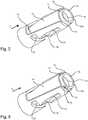
- the sleeve member (6)will continue in the FIGS. 5 and 6 shown in detail in an isometric view.
- Fig. 8a side view of the sleeve member (6) is shown, wherein this is arranged on the syringe body (3).
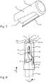
- the cap member (11)is in Fig. 7 detailed in an isometric view.
- the locking in the axial directionis made possible by a projection (28) or a thickening at the distal end (4) of the syringe body, against which the collar element (7) rests with its distal end.
- the collar element (7)is designed essentially as a hollow circular cylinder (12).
- the circular cylinder (12)has a lateral surface (12a) on which two guide projections (9) are arranged.
- the guide projections (9)extend radially outward from the lateral surface (12a) and are arranged diametrically opposite one another. Furthermore, these are designed as a circular cylinder or as a pin.
- These two guide projections (9)are each guided in a guide slot (10) of the sleeve element (6) during a relative movement of the syringe body (3) to the sleeve element (6) substantially along the axial direction (X).
- the collar element (7)is arranged rotatably in a circumferential direction (U) on the distal end region (8) of the syringe body (3).
- the cap element (11)has a lancing means protection device (13) in which the piercing means (5) can be arranged.
- the sleeve element (6)comprises a distal opening (14), wherein the inner diameter (14a) of this distal opening (14) is greater than the outer diameter (13d) of the lancing device (13), so that the lancet protection device (13) within the Sleeve element (6) can be arranged.
- the distal end (26) and a subsequent distal region of the lancing means (5)are arranged in a cavity of the lancing device (13).
- the cavitycomprises a first region (13a), wherein the lancing device (13) is in this first region on the inner walls thereof.
- a third region (13c) of the lancet protection device (13)the cavity continues to extend beyond the distal end (4) of the syringe body.
- a second region (13b)in which the inner diameter of the cavity increases from the first region (13a) to the third region (13c).
- the lancet protection device (13)extends over the distal end region (8) of the syringe body (3) up to the collar element (7).
- the lancet protection device (13)is in operative contact with the collar element (7), whereby the collar element (7) can be locked with respect to a rotation.
- the cap member (11)further comprises two diametrically opposed wing-like elements (17). This is also in Fig. 7 to recognize. These wing-like elements (17) are designed to be complementary to receptacles (18) of the sleeve element (6). The receptacles are designed in the form of recesses in the sleeve element (6). This is also in the FIGS. 5 and 6 to recognize. If the cap element (11) is arranged on the sleeve element (6), the two wing-like elements (17) can be received in the two receptacles (18) of the sleeve element (6).
- the lancet protection device (13)extends through the distal opening (14) of the sleeve element (6). It is also conceivable that at least one wing-like element (17) is in operative contact with the collar element (7), whereby the collar element (7) can be locked with respect to a rotation.
- the distal portion (19) of the sleeve member (6)includes the distal opening (14) of the sleeve member (6) and a circular ring (30) surrounding the distal opening (14) of the sleeve member (6).
- the outer diameter of the circular ring (30)is smaller than the outer diameter of the adjoining region of the sleeve element (6).
- a first (30a) and a second end face (31)are formed on the sleeve member (6).
- the cap element (11)is accordingly designed to be complementary, so that in its distal region (20) this has bearing surfaces (32) on the inside, which rest against the two end surfaces (30a, 31).
- FIGS. 1 and 2Embodiments of the safety device (1) are shown, in which the cap element (11) is formed integrally with the lancing device (13).
- the cap element (11)has a distal opening (21).
- the distal opening (21)is designed as a receptacle to receive the lancing means (13).
- the lancing device (13)comprises a flange at its distal end, which is embedded in the receptacle of the distal opening (21) of the cap member (11).
- a safety device (1)which has a spring element (22) in the form of a spiral spring, which is operatively connected to the syringe body (3) and counteracts the relative movement of the sleeve member (6) to the safety device (1). Accordingly, the piercing means (5) remains within the sleeve member (6) until the intended application. In use, the sleeve member (6) must be displaced against the spring force to allow the piercing means (5) to pass through the distal opening (14) of the sleeve member (6).
- the cap member (11) and the sleeve member (7)mutually complementary latching elements (15, 16), so that the cap member (11) and the sleeve member (7) are releasably latched.
- the sleeve element (6)comprises a distal region (19) on which latching elements (15) are arranged. These latching elements (15) can be latched into complementary latching elements (16) which are arranged in a distal region (20) of the cap element (11).
- the latching elements (15) of the sleeve element (6)are arranged on a lateral surface of the circular ring (30).
- a sleeve member (6)which has two receptacles (18) for the wing-like elements (17) of the cap member (11).
- latching elements (15)are arranged, which complementary to corresponding latching elements (16) of the wing-like elements (17) of the cap member (11) (not shown here) are formed and can be latched into this.
- the guide slots (10) of the sleeve element (6)comprise a first (23) and a second gate area (24), which are separated by a along the axial direction (X) of the syringe body (3) extending fictitious parting line (25) the guide projection (9) in a starting position in the first gate area (23) can be arranged and from the first (23) in the second gate area (24) can be converted into an end position by crossing the dividing line (25), if a distal end (26) of the piercing means (5) during the relative movement of the syringe body (3) Sleeve member (6) at the level of the distal opening (14) of the sleeve member (6) is arranged. This is in the FIGS. 5, 6 and 8th to recognize, in Fig. 8 the guide projection (9) has crossed the parting line (25), whereby the distal end (26) of the piercing means (5) already projects beyond the distal opening (14) of the sleeve element (6).
- the sleeve element (6)has an end region (27).
- the guide projections (9)can be transferred from the second gate area (24) by means of a gate of the second gate area (24) into an end area (27).
- a relative movement of the sleeve element (6) to the syringe body (3)is at least substantially limited along the axial direction (X).
Landscapes
- Health & Medical Sciences (AREA)
- Engineering & Computer Science (AREA)
- Heart & Thoracic Surgery (AREA)
- Vascular Medicine (AREA)
- Anesthesiology (AREA)
- Biomedical Technology (AREA)
- Hematology (AREA)
- Life Sciences & Earth Sciences (AREA)
- Animal Behavior & Ethology (AREA)
- General Health & Medical Sciences (AREA)
- Public Health (AREA)
- Veterinary Medicine (AREA)
- Environmental & Geological Engineering (AREA)
- Diabetes (AREA)
- Infusion, Injection, And Reservoir Apparatuses (AREA)
Description
Translated fromGermanDie Erfindung betrifft eine Sicherheitsvorrichtung zur Vermeidung von Stichverletzungen für eine Spritze mit einem Spritzenkörper und einem an dem distalen Ende des Spritzenkörpers angeordneten Stechmittel, umfassend unter anderem ein sich entlang einer axialen Richtung (X) erstreckendes Hülsenelement, welches zumindest teilweise das Stechmittel und den Spritzenkörper umschließt, und ein Kragenelement, welches an einem distalen Endbereich des Spritzenkörpers anordenbar ist und die Sicherheitsvorrichtung in axialer Richtung (X) arretiert, wobei das Kragenelement zumindest einen Führungsvorsprung aufweist, welcher in zumindest einer Führungskulisse des Hülsenelements eingreift.The invention relates to a safety device for preventing puncture injuries for a syringe with a syringe body and a lancing means arranged at the distal end of the syringe body, comprising inter alia a sleeve element extending along an axial direction (X) which at least partially surrounds the lancing means and the syringe body and a collar member which is locatable at a distal end portion of the syringe body and locks the safety device in the axial direction (X), the collar member having at least one guide projection engaging in at least one guide slot of the sleeve member.
Gattungsgemäße Sicherheitsvorrichtungen zur Vermeidung von Stichverletzungen sind aus dem Stand der Technik bekannt. Insbesondere bei vorgefüllten Spritzen ist die Verwendung derartiger Sicherheitsvorrichtungen sinnvoll. Die Handhabung derartiger Spritzen ist sehr einfach, da das Medium nicht vor der Anwendung in die Spritze transferiert werden muss. Weiterhin ist, selbst im Notfall, die Wahrscheinlichkeit der Anwendung eines falschen Medikaments sehr gering. Für Impfstoffe und zahlreiche andere Medikamente sind sie heutzutage das Primärpackmittel erster Wahl. Diese Spritzen sind üblicherweise aus Glas oder Kunststoff (beispielsweise COC, COP) hergestellt und müssen mit Schutzkappen ausgestattet sein, um Beschädigungen und/oder eine Kontaminierung der Kanüle vor der Anwendung der Spritze zu vermeiden. Darüber hinaus ist es wichtig, nach Gebrauch der Spritze die Kanüle zu sichern, um Stichverletzungen zu vermeiden. Dabei kann ein unvorsichtiges Wiederaufsetzten der Schutzkappe auf die Kanüle Stichverletzungen verursachen. Oft ist die entsprechende Schutzkappe nicht mehr auffindbar oder es wird vergessen, diese wiederaufzusetzen, wodurch ein vermeidbares Verletzungsrisiko gegeben ist.Generic safety devices for preventing puncture injuries are known from the prior art. Especially with prefilled syringes, the use of such safety devices makes sense. The handling of such syringes is very simple, since the medium does not have to be transferred into the syringe before use. Furthermore, even in an emergency, the likelihood of using a wrong drug is very low. For vaccines and many other medicines, they are the primary packaging of choice today. These syringes are usually made of glass or plastic (eg COC, COP) and must be equipped with protective caps to prevent damage and / or contamination of the cannula prior to use of the syringe. In addition, it is important to secure the cannula after use of the syringe to avoid puncture injuries. Careless re-insertion of the protective cap onto the cannula can cause puncture injuries. Often the corresponding one Protective cap can no longer be found or it is forgotten to restart this, which is an avoidable risk of injury.
Demzufolge wurden Nadelschutzeinrichtungen entwickelt, welche fest mit der Spritze verbunden sind und die Nadel nach Verwendung der Spritze automatisch wieder aufnehmen. Eine solche Nadelschutzeinrichtung ist beispielsweise in
Im Bereich der vorgefüllten Spritzen wird bereits vor dem Abfüllprozess eine Schutzkappe beziehungsweise eine Sicherheitsvorrichtung zur Vermeidung von Stichverletzungen auf dem Spritzenkörper montiert und in einer Standardverpackung beispielsweise einem Spritzennest sterilisiert wird. Man spricht in diesem Zusammenhang auch von Ready to Use (RTU) bzw. Ready to Sterilize (RTS) Spritzen. In der Regel sollen die Sicherheitsvorrichtungen derart ausgelegt sein, dass sie leichtgängig zu betätigen sind, um einen optimalen Komfort für den Anwender zu gewährleisten. Demzufolge ist es möglich, dass die Spritzen bereits während des Transports ungewollt betätigt werden. Auch können die Spritzen versehentlich während der Benutzung ausgelöst werden. Dies kann die Spritze unter Umständen komplett unbrauchbar machen. Das beinhaltete Medikament kann nicht verabreicht werden. Überdies kann es ebenso zu Verletzungen des Anwenders oder des Patienten kommen, falls dieser die Sicherheitsvorrichtung unabsichtlich Eine gattungsgemäße Sicherheitsvorrichtung ist auch aus
Aufgabe der vorliegenden Erfindung ist es, eine Sicherheitsvorrichtung zur Vermeidung von Stichverletzungen für eine Spritze zur Verfügung zu stellen, welche die eingangs genannten Probleme löst.The object of the present invention is to provide a safety device for preventing puncture injuries for a syringe, which solves the problems mentioned above.
Diese Aufgabe wird gelöst durch eine Sicherheitsvorrichtung mit den Merkmalen von Anspruch 1.This object is achieved by a safety device having the features of
Da durch das Kappenelement das Hülsenelement bezüglich der Relativbewegung des Spritzenkörpers zu dem Hülsenelement arretierbar ist, wird effektiv ein unerwünschtes Hervortreten des Stechmittels, welches eine Kanüle, eine Nadel oder auch eine Lanzette sein kann, durch eine entsprechende Öffnung in der Sicherheitsvorrichtung unterbunden. Beschädigungen und Kontamination des Stechmittels werden demnach verhindert. Der Anwender der Spritze muss zunächst das Kappenelement von dem Hülsenelement abziehen, bevor die Spritze angewendet werden kann. Demnach wird ebenso das Risiko eines versehentlichen Betätigens verringert. Es wäre denkbar, an dem Kappenelement eine Markierung oder einen Hinweis anzubringen. Der Anwender wäre somit gezwungen, diese Markierung beziehungsweise den Hinweis vor der Anwendung der Spritze wahrzunehmen. Eine derartige Markierung beziehungsweise ein derartiger Hinweis könnte farblich und/oder haptisch und/oder anderweitig ausgestaltet sein.Since the sleeve element can be locked by the cap element with respect to the relative movement of the syringe body to the sleeve element, an undesired emergence of the piercing means, which may be a cannula, a needle or even a lancet, is effectively prevented by a corresponding opening in the safety device. Damage and contamination of the lancing agent are therefore prevented. The user of the syringe must first withdraw the cap member from the sleeve member before the syringe can be applied. Accordingly, the risk of accidental actuation is also reduced. It would be conceivable to attach a mark or an indication to the cap element. The user would thus be forced to perceive this marking or the indication before the use of the syringe. Such a mark or such a reference could be colored and / or haptic and / or otherwise configured.
Gemäß einer besonders bevorzugten Ausführungsform ist das Kragenelement im Wesentlichen als hohler Kreiszylinder ausgebildet. Bevorzugt weist der Kreiszylinder eine Mantelfläche auf, an der der zumindest eine Führungsvorsprung angeordnet ist. Vorzugsweise erstreckt sich der zumindest eine Führungsvorsprung radial von der Mantelfläche weg. Weiterhin bevorzugt ist der Führungsvorsprung als Kreiszylinder beziehungsweise als Stift ausgebildet. Vorteilhafterweise sind an der Mantelfläche zwei sich diametral gegenüberliegende Führungsvorsprünge angeordnet. Demzufolge würde auch das Hülsenelement zwei sich diametral gegenüberliegende Führungskulissen aufweisen, in denen jeweils ein Führungsvorsprung geführt wird. Erfindungsgemäß ist das Kragenelement weiterhin in einer Umfangsrichtung (U) rotierbar an dem distalen Endbereich des Spritzenkörpers angeordnet. Bei einer Anwendung der Spritze wird die Spritze mit der Sicherheitseinrichtung gegen die Haut des Patienten gedrückt. Durch die Relativbewegung des Spritzenkörpers zu dem Hülsenelement und die Führung des Führungsvorsprungs in der Führungskulisse wird eine Rotation des Kragenelements entlang einer Umfangsrichtung (U) verursacht. Das Hülsenelement schiebt sich dadurch über den Spritzenkörper, wodurch das Stechmittel, welches eine Kanüle, eine Nadel oder auch eine Lanzette sein kann, durch eine entsprechende Öffnung in dem Hülsenelement hindurchtritt. Somit wird eine Rotation des Hülsenelements auf der Haut des Patienten um die Einstichstelle herum vermieden.According to a particularly preferred embodiment, the collar element is designed substantially as a hollow circular cylinder. Preferably, the circular cylinder has a lateral surface on which the at least one guide projection is arranged. Preferably, the at least one guide projection extends radially away from the lateral surface. Further preferably, the guide projection is designed as a circular cylinder or as a pin. Advantageously, two diametrically opposite guide projections are arranged on the lateral surface. As a result, the sleeve element would also have two diametrically opposite guide slots, in each of which a guide projection is guided. According to the invention, the collar element is furthermore in a circumferential direction (U) rotatably disposed at the distal end portion of the syringe body. In an application of the syringe, the syringe is pressed with the safety device against the skin of the patient. By the relative movement of the syringe body to the sleeve member and the guide of the guide projection in the guide slot, a rotation of the collar member along a circumferential direction (U) is caused. The sleeve member thereby slides over the syringe body, whereby the piercing means, which may be a cannula, a needle or even a lancet, passes through a corresponding opening in the sleeve member. Thus, rotation of the sleeve member on the skin of the patient around the puncture site is avoided.
Vorzugsweise ist der Spritzenkörper als hohler Kreiszylinder ausgestaltet und weist in seinem distalen Endbereich ein konisches Endstück auf, an welchem das Stechmittel angeordnet ist. Bevorzugt ist an dem konischen Endstück ein Vorsprung ausgebildet, an welchem eine Stirnfläche des distalen Endes des Kragenelements eingreifbar ist, wodurch das Kragenelement und somit die Sicherheitsvorrichtung in axialer Richtung arretierbar ist. Weiterhin bevorzugt ist auch die Sicherheitsvorrichtung im Wesentlichen in Form eines hohlen Kreiszylinders ausgestaltet.Preferably, the syringe body is designed as a hollow circular cylinder and has in its distal end region on a conical end piece, on which the piercing means is arranged. Preferably, a projection is formed on the conical end piece, on which an end face of the distal end of the collar element is engageable, whereby the collar element and thus the safety device can be locked in the axial direction. Further preferably, the safety device is designed substantially in the form of a hollow circular cylinder.
Gemäß der Erfindung weist das Kappenelement eine Stechmittelschutzeinrichtung auf, in welcher das Stechmittel anordenbar ist. Durch eine derartige Stechmittelschutzeinrichtung wird ein weiterer Schutz des Stechmittels vor Beschädigungen und insbesondere vor Kontamination gewährleistet.According to the invention, the cap member has a lancing device, in which the lancing means can be arranged. By such a lancing device further protection of the lancing agent from damage and in particular from contamination is ensured.
Vorzugsweise weist das Hülsenelement eine distale Öffnung auf. Bevorzugt ist dabei der Innendurchmesser der distalen Öffnung zumindest abschnittsweise größer als der Außendurchmesser der Stechmittelschutzeinrichtung, so dass die Stechmittelschutzeinrichtung innerhalb des Hülsenelements anordenbar ist.Preferably, the sleeve member has a distal opening. Preferably, the inner diameter of the distal opening is at least partially larger than the outer diameter of the lancing device, so that the lancing device can be arranged within the sleeve element.
Erfindungsgemäß ist die Stechmittelschutzeinrichtung mit dem Kragenelement in Wirkkontakt bringbar, wodurch das Kragenelement bezüglich einer Rotation arretierbar ist. Ein solcher Wirkkontakt kann beispielweise ein reibschlüssiger Kontakt sein. Es wäre aber auch denkbar, dass die Stechmittelschutzeinrichtung und das Kragenelement zueinander korrespondierende Rasteinrichtungen aufweisen, welche eine Rotation des Kragenelements verhindern.According to the invention, the lancet protection device can be brought into operative contact with the collar element, as a result of which the collar element can be locked in relation to a rotation. Such a contact can be, for example, a frictional contact. However, it would also be conceivable for the lancet protection device and the collar element to have mutually corresponding latching devices which prevent rotation of the collar element.
Gemäß einer bevorzugten Ausführungsform weisen das Kappenelement und das Hülsenelement zueinander komplementäre Rastelemente auf, so dass das Kappenelement und das Hülsenelement trennbar verrastbar sind. Es wäre vorstellbar, dass ein Rastelement eine Sollbruchstelle aufweist, welche vor der Anwendung aufgebrochen werden muss, um ein Abziehen des Kappenelements von dem Hülsenelement zu ermöglichen. Es wäre aber auch denkbar, dass ein Einrasten der Rastelemente auch nach der Anwendung der Spritze ermöglicht ist. Somit wäre es ermöglicht, dass Kappenelement nach dem Gebrauch der Spritze wieder fest auf dem Hülsenelement anzuordnen, wodurch das Hülsenelement bezüglich der Relativbewegung des Spritzenkörpers zu dem Hülsenelement wiederum arretierbar wäre. Demzufolge ist eine gefahrlose Entsorgung der gebrauchten Spritze möglich, welche somit kein Verletzungsrisiko mehr darstellt.According to a preferred embodiment, the cap member and the sleeve member to each other complementary latching elements, so that the cap member and the sleeve member are separably latched. It would be conceivable that a latching element has a predetermined breaking point, which must be broken before use in order to allow removal of the cap member of the sleeve member. It would also be conceivable that a locking of the locking elements is made possible even after the application of the syringe. Thus, it would be possible for the cap element to be fixedly arranged on the sleeve element after use of the syringe, as a result of which the sleeve element would again be lockable with respect to the relative movement of the syringe body to the sleeve element. Consequently, a safe disposal of the used syringe is possible, which thus no longer represents a risk of injury.
Gemäß eines weiteren bevorzugten Gedankens der Erfindung umfasst das Kappenelement zumindest ein flügelartiges Element, welches in zumindest einer Aufnahme des Hülsenelements aufnehmbar ist. Weiterhin bevorzugt weist das Kappenelement zwei flügelartige Elemente auf, welche diametral in jeweils zwei Aufnahmen des Hülsenelements aufnehmbar sind. Besonders bevorzugt sind die beiden flügelartigen Elemente diametral sich gegenüberliegend an dem Kappenelement angeordnet.According to a further preferred concept of the invention, the cap element comprises at least one wing-like element, which can be received in at least one receptacle of the sleeve element. Further preferably, the cap member on two wing-like elements which are accommodated diametrically in two receptacles of the sleeve member. Particularly preferably, the two wing-like elements are arranged diametrically opposite one another on the cap element.
Nach einer weiteren bevorzugten Ausführungsform ist zumindest ein flügelartiges Element mit dem Kragenelement in Wirkkontakt bringbar, wodurch das Kragenelement bezüglich einer Rotation arretierbar ist. Ein solcher Wirkkontakt kann beispielweise ein reibschlüssiger Kontakt sein. Es wäre aber auch denkbar, dass die Stechmittelschutzeinrichtung und das Kragenelement zueinander korrespondierende Rasteinrichtungen aufweisen, welche eine Rotation des Kragenelements verhindern.According to a further preferred embodiment, at least one wing-like element can be brought into operative contact with the collar element, as a result of which the collar element can be locked with respect to a rotation. Such a contact can be, for example, a frictional contact. However, it would also be conceivable for the lancet protection device and the collar element to have mutually corresponding latching devices which prevent rotation of the collar element.
Gemäß einer weiteren bevorzugten Ausführungsform ist an dem zumindest einen flügelartigen Element des Kappenelements zumindest ein Rastelement angeordnet, welches in zumindest ein komplementäres Rastelement, das in der zumindest einen Aufnahme des Hülsenelements angeordnet ist, einrastbar ist.According to a further preferred embodiment, at least one latching element is arranged on the at least one wing-like element of the cap element, which can be latched into at least one complementary latching element which is arranged in the at least one receptacle of the sleeve element.
Es wär auch denkbar, dass das Hülsenelement einen distalen Bereich aufweist, an welchem zumindest ein Rastelement angeordnet ist. Vorteilhafterweise ist das zumindest eine Rastelement in zumindest ein komplementäres Rastelement einrastbar, welches in einem distalen Bereich des Kappenelements angeordnet ist.It would also be conceivable that the sleeve element has a distal region, on which at least one latching element is arranged. Advantageously, the at least one latching element can be latched into at least one complementary latching element, which is arranged in a distal region of the cap element.
Vorzugsweise ist das Kappenelement integral mit der Stechmittelschutzeinrichtung ausgebildet. Eine derartige Ausführung der Sicherheitsvorrichtung hat eine kostengünstige und einfache Herstellung zum Vorteil.Preferably, the cap member is formed integrally with the lancing device. Such an embodiment of the safety device has an inexpensive and simple production to the advantage.
Es ist aber auch denkbar, dass das Kappenelement eine distale Öffnung aufweist, wobei die distale Öffnung als Aufnahme ausgebildet ist, um die Stechmittelschutzeinrichtung aufzunehmen. Eine solche Ausgestaltung ermöglicht es, das Kappenelement und die Stechmittelschutzeinrichtung aus unterschiedlichen Materialien herzustellen. Es wäre demnach denkbar, die Stechmittelschutzeinrichtung aus einem elastischen Material, beispielsweise Gummi herzustellen. Ein solches elastische Material begünstigt eine Reduzierung des Beschädigungsrisikos des Stechmittels.However, it is also conceivable that the cap member has a distal opening, wherein the distal opening is formed as a receptacle to receive the lancet protection device. Such a configuration makes it possible to produce the cap member and the lancing device of different materials. It would therefore be conceivable to produce the lancet protection device from an elastic material, for example rubber. Such elastic material promotes a reduction of the risk of damage of the lancing agent.
Vorzugsweise weist die Sicherheitsvorrichtung mindestens ein Federelement auf, das mit dem Spritzenkörper wirkverbunden ist und der Relativbewegung des Spritzenkörpers zu der Sicherheitsvorrichtung entgegenwirkt. Demnach bleibt die Kanüle bis zur vorgesehenen Anwendung innerhalb des Hülsenelements. Bei der Anwendung muss das Hülsenelement gegen die Federkraft verschoben werden, damit die Kanüle durch die Öffnung des Hülsenelements hindurchtreten kann. Nach Gebrauch der Spritze schiebt sich automatisch, angetrieben durch die Federkraft des Federelements, das Hülsenelement wieder über die Kanüle. Durch die Führung des Führungsvorsprungs in der Führungskulisse rotiert das Kragenelement entgegen der Umfangsrichtung (U). Der Anwender ist somit vor Stichverletzungen mit der gebrauchten kontaminierten Kanüle geschützt. Bevorzugt umfasst das Federelement eine Spiralfeder. Denkbar sind aber auch anderweitige Federarten, wie beispielsweise Schenkelfedern oder Torsionsfedern. Ferner wäre vorstellbar, das Federelement als ein Elastomer auszubilden.Preferably, the safety device has at least one spring element, which is operatively connected to the syringe body and counteracts the relative movement of the syringe body to the safety device. Thus, the cannula remains within the sleeve member until intended use. In use, the sleeve member must be displaced against the spring force to allow the cannula to pass through the opening of the sleeve member. After use of the syringe, the sleeve element pushes automatically over the cannula, driven by the spring force of the spring element. By guiding the guide projection in the guide slot, the collar element rotates counter to the circumferential direction (U). The user is thus protected against puncture injuries with the used contaminated cannula. Preferably, the spring element comprises a spiral spring. Also conceivable are other types of springs, such as torsion springs or torsion springs. Furthermore, it would be conceivable to form the spring element as an elastomer.
Nach einem weiteren vorteilhaften Gedanken der Erfindung umfasst die zumindest eine Führungskulisse einen ersten und einen zweiten Kulissenbereich, die durch eine entlang der axialen Richtung (X) des Spritzenkörpers verlaufende fiktive Trennlinie voneinander getrennt sind, wobei der Führungsvorsprung in einer Ausgangsstellung in dem ersten Kulissenbereich anordenbar ist und von dem ersten in den zweiten Kulissenbereich in eine Endstellung durch Überschreiten der Trennlinie überführbar ist, wenn ein distales Ende des Stechelements bei der Relativbewegung von Spritzenkörper zu Hülsenelement auf der Höhe der distalen Öffnung des Hülsenelements angeordnet ist.According to a further advantageous concept of the invention, the at least one guide slot comprises a first and a second gate area separated by a fictitious parting line extending along the axial direction (X) of the syringe body, the guide projection being locatable in a home position in the first gate area and can be transferred from the first to the second gate area in an end position by exceeding the dividing line, when a distal end of the lancing element is arranged at the height of the distal opening of the sleeve member in the relative movement of the syringe body to sleeve member.
Demnach ist der Führungsvorsprung des Kragenelements von dem ersten Kulissenbereich in den zweiten Kulissenbereich überführbar. Diese Überführung findet statt, wenn der Führungsvorsprung eine fiktive Trennlinie, welche den ersten und den zweiten Kulissenbereich voneinander trennt, überschreitet. Befindet sich der Führungsvorsprung in dem ersten Kulissenbereich, also in einer Ausgangsstellung, so wurde die Spritze noch nicht ausgelöst, d.h. das Stechmittel hat die Sicherheitsvorrichtung noch nicht verlassen. Befindet sich der Führungsvorsprung in dem zweiten Kulissenbereich, so ist das Stechmittel aus der Sicherheitsvorrichtung bereits ausgetreten, so dass eine Injektion möglich ist. Beim Übergang von dem ersten Kulissenbereich zu dem zweiten Kulissenbereich, also genau dann, wenn der Führungsvorsprung die Trennlinie überschreitet, befindet sich das distale Ende des Stechmittels auf der Höhe der distalen Öffnung der Sicherheitsvorrichtung.Accordingly, the guide projection of the collar element can be transferred from the first gate area into the second gate area. This transfer takes place when the guide projection exceeds a fictitious parting line separating the first and second gate sections. If the guide projection is in the first gate area, ie in a starting position, then the syringe has not yet been triggered, i. the lancing agent has not yet left the safety device. If the guide projection is located in the second gate area, then the piercing means has already left the safety device, so that an injection is possible. In the transition from the first gate area to the second gate area, ie just when the guide projection exceeds the dividing line, the distal end of the piercing means is at the level of the distal opening of the safety device.
Bevorzugt ist der Führungsvorsprung von dem zweiten Kulissenbereich mittels einer Kulisse des zweiten Kulissenbereichs in einen Endbereich überführbar, in welchem eine Relativbewegung des Hülsenelements zu dem Spritzenkörper im Wesentlichen entlang der axialen Richtung (X) zumindest eingeschränkt ist. Durch eine derartige Ausgestaltung ist ein weiteres Verschieben des Hülsenelements relativ zum Spritzenkörper zumindest eingeschränkt, bevorzugt verhindert. Demzufolge ist ein weiteres Austreten des Stechmittels aus der Sicherheitsvorrichtung nach der Anwendung der Spritze unterbunden.Preferably, the guide projection is convertible from the second gate area by means of a gate of the second gate area in an end region in which a relative movement of the sleeve member to the syringe body at least along the axial direction (X) is at least limited. By such a configuration further displacement of the sleeve member relative to the syringe body is at least limited, preferably prevented. Consequently, further leakage of the lancing agent from the safety device after application of the syringe is prevented.
Weitere Vorteile, Ziele und Eigenschaften der vorliegenden Erfindung werden anhand nachfolgender Beschreibung der anliegenden Figuren erläutert. Gleichartige Komponenten können in den verschiedenen Ausführungsformen gleiche Bezugszeichen aufweisen.Further advantages, objects and characteristics of the present invention will be explained with reference to the following description of the enclosed figures. Similar components may have the same reference numerals in the various embodiments.
In den Figuren zeigen:
- Fig.1
- eine Schnittdarstellung einer Spritze mit Sicherheitsvorrichtung gemäß einer Ausführungsform;
- Fig.2
- eine Schnittdarstellung einer Spritze mit Sicherheitsvorrichtung gemäß einer weiteren Ausführungsform;
- Fig.3
- eine Schnittdarstellung einer Spritze mit Sicherheitsvorrichtung gemäß einer weiteren Ausführungsform;
- Fig.4
- eine Schnittdarstellung einer Spritze mit Sicherheitsvorrichtung gemäß einer weiteren Ausführungsform;
- Fig.5
- eine isometrische Ansicht eines Hülsenelements gemäß einer weiteren Ausführungsform;
- Fig.6
- eine isometrische Ansicht eines Hülsenelements gemäß einer weiteren Ausführungsform;
- Fig.7
- eine isometrische Ansicht eines Kappenelements gemäß einer weiteren Ausführungsform;
- Fig.8
- eine Seitenansicht einer an einem Spritzenkörper angeordneten Sicherheitsvorrichtung.
- Fig.1
- a sectional view of a syringe with safety device according to an embodiment;
- Fig.2
- a sectional view of a syringe with safety device according to another embodiment;
- Figure 3
- a sectional view of a syringe with safety device according to another embodiment;
- Figure 4
- a sectional view of a syringe with safety device according to another embodiment;
- Figure 5
- an isometric view of a sleeve member according to another embodiment;
- Figure 6
- an isometric view of a sleeve member according to another embodiment;
- Figure 7
- an isometric view of a cap member according to another embodiment;
- Figure 8
- a side view of a arranged on a syringe body safety device.
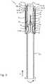
In den
Weiterhin ist eine Sicherheitsvorrichtung (1) zur Vermeidung von Stichverletzungen für eine Spritze (2) gezeigt, welche einen Spritzenkörper (3) und ein an dem distalen Ende (4) des Spritzenkörpers (3) angeordnetes Stechmittel (5) umfasst. Die Sicherheitsvorrichtung (1) umfasst ein sich entlang einer axialen Richtung (X) erstreckendes Hülsenelement (6), welches zumindest teilweise das Stechmittel (5) und den Spritzenkörper (3) umschließt, und ein Kragenelement (7), welches an einem distalen Endbereich (8) des Spritzenkörpers (3) angeordnet ist und die Sicherheitsvorrichtung (1) in axialer Richtung (X) arretiert. Ferner weist die Sicherheitsvorrichtung (1) ein Kappenelement (11) auf, welches zumindest abschnittsweise über dem Hülsenelement (6) anordenbar ist und durch welches das Hülsenelement (6) bezüglich der Relativbewegung des Spritzenkörpers (3) zu dem Hülsenelement (6) arretierbar ist. Das Hülsenelement (6) und das Kappenelement (11) sind dabei im Wesentlichen zylindrisch ausgestaltet. Das Hülsenelement (6) wird weiterhin in den
Die Arretierung in axialer Richtung wird durch einen Vorsprung (28) bzw. eine Verdickung an dem distalen Ende (4) des Spritzenkörpers ermöglicht, an welchem das Kragenelement (7) mit seinem distalen Ende anliegt.The locking in the axial direction is made possible by a projection (28) or a thickening at the distal end (4) of the syringe body, against which the collar element (7) rests with its distal end.
Das Kragenelement (7) ist im Wesentlichen als hohler Kreiszylinder (12) ausgebildet. Der Kreiszylinder (12) weist eine Mantelfläche (12a) auf, an der zwei Führungsvorsprünge (9) angeordnet sind. Die Führungsvorsprünge (9) erstrecken sich radial von der Mantelfläche (12a) nach außen weg und sind diametral gegenüberliegend angeordnet. Weiterhin sind diese als Kreiszylinder beziehungsweise als Stift ausgebildet. Diese beiden Führungsvorsprünge (9) sind jeweils in einer Führungskulisse (10) des Hülsenelements (6) bei einer Relativbewegung des Spritzenkörpers (3) zu dem Hülsenelement (6) im Wesentlichen entlang der axialen Richtung (X) geführt. Ferner ist das Kragenelement (7) in einer Umfangsrichtung (U) rotierbar an dem distalen Endbereich (8) des Spritzenkörpers (3) angeordnet.The collar element (7) is designed essentially as a hollow circular cylinder (12). The circular cylinder (12) has a lateral surface (12a) on which two guide projections (9) are arranged. The guide projections (9) extend radially outward from the lateral surface (12a) and are arranged diametrically opposite one another. Furthermore, these are designed as a circular cylinder or as a pin. These two guide projections (9) are each guided in a guide slot (10) of the sleeve element (6) during a relative movement of the syringe body (3) to the sleeve element (6) substantially along the axial direction (X). Furthermore, the collar element (7) is arranged rotatably in a circumferential direction (U) on the distal end region (8) of the syringe body (3).
Das Kappenelement (11) weist eine Stechmittelschutzeinrichtung (13) auf, in welcher das Stechmittel (5) anordenbar ist. Darüber hinaus umfasst das Hülsenelement (6) eine distale Öffnung (14), wobei der Innendurchmesser (14a) dieser distalen Öffnung (14) größer ist als der Außendurchmesser (13d) der Stechmittelschutzeinrichtung (13), so dass die Stechmittelschutzeinrichtung (13) innerhalb des Hülsenelements (6) anordenbar ist.The cap element (11) has a lancing means protection device (13) in which the piercing means (5) can be arranged. In addition, the sleeve element (6) comprises a distal opening (14), wherein the inner diameter (14a) of this distal opening (14) is greater than the outer diameter (13d) of the lancing device (13), so that the lancet protection device (13) within the Sleeve element (6) can be arranged.
Das distale Ende (26) und ein anschließender distaler Bereich des Stechmittels (5) sind dabei in einem Hohlraum der Stechmittelschutzeinrichtung (13) angeordnet. Der Hohlraum umfasst einen ersten Bereich (13a), wobei die Stechmittelschutzeinrichtung (13) in diesem ersten Bereich an dessen Innenwänden anliegend ist. In einem dritten Bereich (13c) der Stechmittelschutzeinrichtung (13) erstreckt sich der Hohlraum weiterhin über das distale Ende (4) des Spritzenkörpers. Zwischen dem ersten (13a) und dem dritten Bereich (13c) befindet sich ein zweiter Bereich (13b), in dem sich der Innendurchmesser des Hohlraums ausgehend von dem ersten Bereich (13a) bis zu dem dritten Bereich (13c) vergrößert. Die Stechmittelschutzeinrichtung (13) erstreckt sich über den distalen Endbereich (8) des Spritzenkörpers (3) bis zu dem Kragenelement (7). Die Stechmittelschutzeinrichtung (13) ist mit dem Kragenelement (7) in Wirkkontakt, wodurch das Kragenelement (7) bezüglich einer Rotation arretierbar ist.The distal end (26) and a subsequent distal region of the lancing means (5) are arranged in a cavity of the lancing device (13). The cavity comprises a first region (13a), wherein the lancing device (13) is in this first region on the inner walls thereof. In a third region (13c) of the lancet protection device (13), the cavity continues to extend beyond the distal end (4) of the syringe body. Between the first (13a) and the third area (13c) is located a second region (13b) in which the inner diameter of the cavity increases from the first region (13a) to the third region (13c). The lancet protection device (13) extends over the distal end region (8) of the syringe body (3) up to the collar element (7). The lancet protection device (13) is in operative contact with the collar element (7), whereby the collar element (7) can be locked with respect to a rotation.
Das Kappenelement (11) umfasst weiterhin zwei diametral gegenüberliegende flügelartige Elemente (17). Dies ist auch in
Der distalen Bereich (19) des Hülsenelements (6) umfasst die distale Öffnung (14) des Hülsenelements (6) und einen Kreisring (30), welcher die distale Öffnung (14) des Hülsenelements (6) umrandet. Der Außendurchmesser des Kreisrings (30) ist dabei kleiner als der Außendurchmesser des anschließenden Bereichs des Hülsenelements (6). Somit sind an dem Hülsenelement (6) eine erste (30a) und eine zweite Stirnfläche (31) ausgebildet. Das Kappenelement (11) ist dementsprechend komplementär ausgebildet, so dass dieses in seinem distalen Bereich (20) innenseitig Auflageflächen (32) aufweist, welche an den beiden Stirnflächen (30a, 31) anliegen.The distal portion (19) of the sleeve member (6) includes the distal opening (14) of the sleeve member (6) and a circular ring (30) surrounding the distal opening (14) of the sleeve member (6). The outer diameter of the circular ring (30) is smaller than the outer diameter of the adjoining region of the sleeve element (6). Thus, a first (30a) and a second end face (31) are formed on the sleeve member (6). The cap element (11) is accordingly designed to be complementary, so that in its distal region (20) this has bearing surfaces (32) on the inside, which rest against the two end surfaces (30a, 31).
In den
In den
Die Stechmittelschutzeinrichtung (13) umfasst dabei einen Flansch an dessen distalen Ende, welcher in der Aufnahme der distalen Öffnung (21) des Kappenelements (11) eingebettet ist.The lancing device (13) comprises a flange at its distal end, which is embedded in the receptacle of the distal opening (21) of the cap member (11).
In
Gemäß den Ausführungsformen, gezeigt in den
In
Die Führungskulissen (10) des Hülsenelements (6) umfassen einen ersten (23) und einen zweiten Kulissenbereich (24), welche durch eine entlang des axialen Richtung (X) des Spritzenkörpers (3) verlaufenden fiktiven Trennlinie (25) voneinander getrennt sind, wobei der Führungsvorsprung (9) in einer Ausgangsstellung in dem ersten Kulissenbereich (23) anordenbar ist und von dem ersten (23) in den zweiten Kulissenbereich (24) in eine Endstellung durch Überschreiten der Trennlinie (25) überführbar ist, wenn ein distales Ende (26) des Stechmittels (5) bei der Relativbewegung von Spritzenkörper (3) zu Hülsenelement (6) auf der Höhe der distalen Öffnung (14) des Hülsenelements (6) angeordnet ist. Dies ist in den
Ferner weist das Hülsenelement (6) einen Endbereich (27) auf. Die Führungsvorsprünge (9) sind dabei von dem zweiten Kulissenbereich (24) mittels einer Kulisse des zweiten Kulissenbereichs (24) in einen Endbereich (27) überführbar. In diesem Endbereich (27) ist eine Relativbewegung des Hülsenelements (6) zu dem Spritzenkörper (3) im Wesentlichen entlang der axialen Richtung (X) zumindest eingeschränkt.Furthermore, the sleeve element (6) has an end region (27). The guide projections (9) can be transferred from the second gate area (24) by means of a gate of the second gate area (24) into an end area (27). In this end region (27), a relative movement of the sleeve element (6) to the syringe body (3) is at least substantially limited along the axial direction (X).
- 11
- Sicherheitsvorrichtungsafety device
- 22
- Spritzesyringe
- 33
- Spritzenkörpersyringe body
- 44
- distales Ende des Spritzenkörpersdistal end of the syringe body
- 55
- Stechmittelpiercing means
- 66
- Hülsenelementsleeve member
- 77
- Kragenelementcollar element
- 88th
- distaler Endbereich des Spritzenkörpersdistal end portion of the syringe body
- 99
- Führungsvorsprungguide projection
- 1010
- Führungskulisseguide link
- 1111
- Kappenelementcap member
- 1212
- hohler Kreiszylinderhollow circular cylinder
- 12a12a
- Mantelfläche des KreiszylindersLateral surface of the circular cylinder
- 1313
- StechmittelschutzeinrichtungPiercing means protection device
- 13a13a
- erster Bereichfirst area
- 13b13b
- zweiter Bereichsecond area
- 13c13c
- dritter Bereichthird area
- 13d13d
- Außendurchmesserouter diameter
- 1414
- distale Öffnung des Hülsenelementsdistal opening of the sleeve element
- 14a14a
- InnendurchmesserInner diameter
- 1515
- Rastelementlocking element
- 1616
- Rastelementlocking element
- 1717
- flügelartiges Elementwing-like element
- 1818
- Aufnahmeadmission
- 1919
- distalen Bereich des Hülsenelementsdistal portion of the sleeve member
- 2020
- distalen Bereich des Kappenelementsdistal portion of the cap member
- 2121
- distale Öffnung des Kappenelementsdistal opening of the cap member
- 2222
- Federelementspring element
- 2323
- erster Kulissenbereichfirst backdrop area
- 2424
- zweiter Kulissenbereichsecond backdrop area
- 2525
- Trennlinieparting line
- 2626
- distales Ende des Stechmittelsdistal end of the lancing agent
- 2727
- Endbereichend
- 2828
- Vorsprunghead Start
- 2929
- ÜbergangsbereichTransition area
- 3030
- Kreisringannulus
- 30a30a
- erste Stirnflächefirst end face
- 3131
- zweite Stirnflächesecond end face
- 3232
- Auflageflächensupport surfaces
- XX
- axiale Richtungaxial direction
- UU
- Umfangsrichtungcircumferentially
Claims (13)
- Safety device (1) for preventing piercing wounds for a syringe (2) having a syringe body (3) and a piercing means (5) arranged at the distal end (4) of the syringe body (3), comprising a sleeve element (6) which extends along an axial direction (X) and at least partially encloses the piercing means (5) and the syringe body (3), and a collar element (7) which can be arranged on a distal end region (8) of the syringe body (3) and locks the safety device (1) in the axial direction (X), wherein the collar element (7) comprises at least one guide projection (9) which engages in at least one guide track (10) of the sleeve element (6),
wherein
the safety device (1) comprises a cap element (11) which can be arranged over the sleeve element (6) at least in portions and by means of which the sleeve element can be locked with respect to the movement of the syringe body (3) relative to the sleeve element (6), wherein the collar element (7) is arranged on the distal end region (8) of the syringe body (3) so as to be able to rotate in a circumferential direction (U), wherein a rotation of the collar element (7) is brought about by the movement of the syringe body (3) relative to the sleeve element (6) and by the guide projection (9) being guided in the guide track (10), wherein
the cap element (11) comprises a piercing means protective device (13) in which the piercing means (5) can be arranged and which can be brought into operative contact with the collar element (7), as a result of which the collar element (7) can be locked with respect to the rotation. - Safety device (1) according to claim 1,
characterised in that
the collar element (7) is substantially formed as a hollow circular cylinder (12), the circular cylinder (12) comprising a lateral surface (12a) on which the at least one guide projection (9) is arranged. - Safety device (1) according to either claim 1 or claim 2,
characterised in that
the sleeve element (6) comprises a distal opening (14), the internal diameter (14a) of the distal opening (14) being larger than the external diameter (13a) of the piercing means protective device (13) at least in portions, such that the piercing means protective device (13) can be arranged inside the sleeve element (6). - Safety device (1) according to any of the preceding claims,
characterised in that
the cap element (11) and the sleeve element (7) comprise complementary latching elements (15, 16) so that the cap element (11) and the sleeve element (7) can be latched together in a separable manner. - Safety device (1) according to any of the preceding claims,
characterised in that
the cap element (11) comprises at least one wing-like element (17) which can be received in at least one receptacle (18) of the sleeve element (6). - Safety device (1) according to claim 5,
characterised in that
at least one wing-like element (17) can be brought into operative contact with the collar element (7), as a result of which the collar element (7) can be locked with respect to a rotation. - Safety device (1) according to claim 5,
characterised in that
at least one latching element (16) is arranged on the at least one wing-like element (17) of the cap element (11), which latching element can be latched into at least one complementary latching element (15) that is arranged in the at least one receptacle (18) of the sleeve element (6). - Safety device (1) according to any of the preceding claims,
characterised in that
the sleeve element (6) comprises a distal region (19) on which at least one latching element (15) is arranged, it being possible for the at least one latching element (15) to be latched into at least one complementary latching element (16) that is arranged in a distal region (20) of the cap element (11). - Safety device (1) according to any of the preceding claims,
characterised in that
the cap element (11) is formed integrally with the piercing means protective device (13). - Safety device (1) according to any of the preceding claims,
characterised in that
the cap element (11) comprises a distal opening (21), the distal opening (21) being formed as a receptacle, in order to receive the piercing means protective device (13). - Safety device (1) according to any of the preceding claims,
characterised in that
the safety device (1) comprises at least one spring element (22) which is operatively connected to the syringe body (3) and counteracts the movement of the sleeve element (6) relative to the safety device (1). - Safety device (1) according to any of the preceding claims,
characterised in that
the at least one guide track (10) comprises a first (23) and a second track region (24), which are separated from one another by a fictive separating line (25) extending along the axial direction (X) of the syringe body (3), it being possible for the guide projection (9) to be arranged in a starting position in the first track region (23) and to be moved from the first track region (23) into an end position in the second track region (24) by passing the separating line (25) when a distal end (26) of the piercing means (5) is arranged at the level of the distal opening (14) of the sleeve element (6) as the syringe body (3) is moved relative to the sleeve element (6). - Safety device (1) according to claim 12,
characterised in that
the at least one guide projection (9) can be moved, by means of a slot of the second track region (24), from the second track region (24) into an end region (27) in which a movement of the sleeve element (6) relative to the syringe body (3) is at least limited substantially along the axial direction (X).
Priority Applications (11)
| Application Number | Priority Date | Filing Date | Title |
|---|---|---|---|
| EP15172173.5AEP3106194B1 (en) | 2015-06-15 | 2015-06-15 | Safety device for a syringe |
| EP18168709.6AEP3369450B1 (en) | 2015-06-15 | 2015-06-15 | Syringe with safety device |
| DK15172173.5TDK3106194T3 (en) | 2015-06-15 | 2015-06-15 | SAFETY DEVICE FOR A SPRAY |
| ES15172173TES2722002T3 (en) | 2015-06-15 | 2015-06-15 | Safety device for a syringe |
| CN201680027465.3ACN107735129B (en) | 2015-06-15 | 2016-05-09 | Safety device for syringe |
| BR112017023573-0ABR112017023573B1 (en) | 2015-06-15 | 2016-05-09 | SAFETY DEVICE FOR A SYRINGE |
| JP2017559504AJP6651547B2 (en) | 2015-06-15 | 2016-05-09 | Safety devices for syringes |
| CA2984417ACA2984417C (en) | 2015-06-15 | 2016-05-09 | Safety device for a syringe |
| PCT/EP2016/060279WO2016202498A1 (en) | 2015-06-15 | 2016-05-09 | Safety device for a syringe |
| KR1020177032737AKR102081779B1 (en) | 2015-06-15 | 2016-05-09 | Safety device for syringe |
| US15/573,047US10653848B2 (en) | 2015-06-15 | 2016-05-09 | Safety device for a syringe |
Applications Claiming Priority (1)
| Application Number | Priority Date | Filing Date | Title |
|---|---|---|---|
| EP15172173.5AEP3106194B1 (en) | 2015-06-15 | 2015-06-15 | Safety device for a syringe |
Related Child Applications (2)
| Application Number | Title | Priority Date | Filing Date |
|---|---|---|---|
| EP18168709.6ADivisionEP3369450B1 (en) | 2015-06-15 | 2015-06-15 | Syringe with safety device |
| EP18168709.6ADivision-IntoEP3369450B1 (en) | 2015-06-15 | 2015-06-15 | Syringe with safety device |
Publications (2)
| Publication Number | Publication Date |
|---|---|
| EP3106194A1 EP3106194A1 (en) | 2016-12-21 |
| EP3106194B1true EP3106194B1 (en) | 2019-03-13 |
Family
ID=53404408
Family Applications (2)
| Application Number | Title | Priority Date | Filing Date |
|---|---|---|---|
| EP15172173.5AActiveEP3106194B1 (en) | 2015-06-15 | 2015-06-15 | Safety device for a syringe |
| EP18168709.6AActiveEP3369450B1 (en) | 2015-06-15 | 2015-06-15 | Syringe with safety device |
Family Applications After (1)
| Application Number | Title | Priority Date | Filing Date |
|---|---|---|---|
| EP18168709.6AActiveEP3369450B1 (en) | 2015-06-15 | 2015-06-15 | Syringe with safety device |
Country Status (10)
| Country | Link |
|---|---|
| US (1) | US10653848B2 (en) |
| EP (2) | EP3106194B1 (en) |
| JP (1) | JP6651547B2 (en) |
| KR (1) | KR102081779B1 (en) |
| CN (1) | CN107735129B (en) |
| BR (1) | BR112017023573B1 (en) |
| CA (1) | CA2984417C (en) |
| DK (1) | DK3106194T3 (en) |
| ES (1) | ES2722002T3 (en) |
| WO (1) | WO2016202498A1 (en) |
Families Citing this family (12)
| Publication number | Priority date | Publication date | Assignee | Title |
|---|---|---|---|---|
| DK3106191T3 (en) | 2015-06-15 | 2019-05-13 | Gerresheimer Regensburg Gmbh | SAFETY DEVICE FOR A SPRAY |
| DK3106193T3 (en) | 2015-06-15 | 2019-03-18 | Gerresheimer Regensburg Gmbh | BODY SPRAY |
| EP3106188B1 (en) | 2015-06-15 | 2019-02-06 | Gerresheimer Regensburg GmbH | Method for mounting a safety device on a syringe |
| DE102015111840B4 (en) | 2015-07-21 | 2019-08-01 | Gerresheimer Bünde Gmbh | Safety device for a syringe |
| DE102015111835A1 (en) | 2015-07-21 | 2017-01-26 | Gerresheimer Regensburg Gmbh | Safety device for a syringe |
| FR3063909B1 (en)* | 2017-03-17 | 2022-03-11 | Biocorp Prod | NEEDLE PROTECTION DEVICE FOR A PRE-FILLED SYRINGE WITH BONDED NEEDLE AND SYRINGE COMPRISING SUCH A DEVICE |
| EP3664874B1 (en) | 2017-08-11 | 2023-10-04 | West Pharmaceutical Services, Inc. | Expandable and automatically retractable collar and method of use thereof |
| CN108992744B (en)* | 2018-06-29 | 2020-11-03 | 苏州沙力医疗器械有限公司 | Rotary locking type safe insulin injection needle |
| EP3958936B1 (en) | 2019-04-26 | 2024-12-18 | Becton Dickinson France | Needle cover with undercut |
| WO2020239844A1 (en)* | 2019-05-29 | 2020-12-03 | Sanofi | Assembly for a drug delivery device and drug delivery device |
| EP3881881A1 (en) | 2020-03-16 | 2021-09-22 | Gerresheimer Regensburg GmbH | Accessory function of a safety device for syringes |
| JP7525955B2 (en) | 2021-04-08 | 2024-07-31 | ラブ ライフサイエンシズ エルエルシー | Prefilled Syringe Safety Devices and Syringes |
Family Cites Families (27)
| Publication number | Priority date | Publication date | Assignee | Title |
|---|---|---|---|---|
| US5591138A (en)* | 1995-08-10 | 1997-01-07 | Vaillancourt; Vincent L. | Protected needle assembly |
| FR2799375B1 (en) | 1999-10-07 | 2002-01-18 | Marc Brunel | SINGLE USE INJECTION DEVICE |
| WO2001054758A1 (en)* | 2000-01-27 | 2001-08-02 | Afra Design Pty. Limited | A single-use syringe |
| US6585691B1 (en)* | 2001-05-11 | 2003-07-01 | Jonathan J. Vitello | Tamper evident end cap assembly for a loaded syringe and process |
| FR2837107B1 (en) | 2002-03-18 | 2005-02-25 | Sedat | NEEDLE PROTECTION DEVICE FOR SYRINGE, AND INJECTION DEVICE COMPRISING SYRINGE AND PROTECTIVE DEVICE |
| US8048035B2 (en)* | 2004-08-06 | 2011-11-01 | Meridian Medical Technologies, Inc. | Automatic injector with needle cover |
| DE102005043805A1 (en)* | 2005-09-14 | 2007-03-22 | Tecpharma Licensing Ag | Positioning device for e.g. injecting pen, has needle guide/cover with positioning unit to guide or position needle, or protective caps or needle holder, so that needle is guided and/or positioned relative to preset entry position by unit |
| GB0600212D0 (en)* | 2006-01-06 | 2006-02-15 | Liversidge Barry P | Medical needle safety device |
| CA2668178C (en)* | 2007-04-24 | 2011-11-15 | Arte Corporation | Combined container-syringe |
| WO2009040603A1 (en)* | 2007-09-25 | 2009-04-02 | Becton Dickinson France | Autoinjector with deshielder comprising tamper evidence means |
| CN102036705A (en) | 2008-05-06 | 2011-04-27 | 海波赛非投资(控股)公司 | Hypodermic needle protector |
| US8663174B2 (en)* | 2009-11-13 | 2014-03-04 | Becton, Dickinson And Company | Hub assembly having a hidden needle for a drug delivery pen |
| GB2478349A (en)* | 2010-03-05 | 2011-09-07 | Owen Mumford Ltd | Injection device having projections reducing the diameter of the syringe passage |
| DK2588165T3 (en)* | 2010-07-02 | 2020-09-14 | Sanofi Aventis Deutschland | SAFETY DEVICE FOR A FILLED SYRINGE Syringe, INJECTION DEVICE AND INJECTION KIT |
| EP2665503B1 (en) | 2011-01-11 | 2024-01-24 | SHL Medical AG | Medicament delivery device |
| WO2013134465A1 (en)* | 2012-03-07 | 2013-09-12 | West Pharmaceutical Services, Inc. | Low radial profile needle safety device |
| CN104307073B (en)* | 2012-09-28 | 2017-02-22 | 上海萌黎国际贸易有限公司 | Sliding bush type needle head protection device and safety syringe |
| KR101287239B1 (en)* | 2012-12-24 | 2013-07-17 | 김종욱 | Billow packing assembly and anti-particle injector using this |
| FR3002740B1 (en) | 2013-03-01 | 2016-01-08 | Transformation Des Elastomeres A Usages Medicaux Et Ind Soc D | NEEDLE PROTECTION DEVICE. |
| WO2014164823A1 (en)* | 2013-03-11 | 2014-10-09 | Auerbach, Judith | Safety system for a needle retaining device |
| JP6211790B2 (en)* | 2013-04-23 | 2017-10-11 | 大成化工株式会社 | Syringe |
| DE102013214442A1 (en)* | 2013-07-24 | 2015-01-29 | Raumedic Ag | Medical injection device |
| DK3106191T3 (en) | 2015-06-15 | 2019-05-13 | Gerresheimer Regensburg Gmbh | SAFETY DEVICE FOR A SPRAY |
| EP3106188B1 (en) | 2015-06-15 | 2019-02-06 | Gerresheimer Regensburg GmbH | Method for mounting a safety device on a syringe |
| DK3106193T3 (en) | 2015-06-15 | 2019-03-18 | Gerresheimer Regensburg Gmbh | BODY SPRAY |
| DE102015111840B4 (en) | 2015-07-21 | 2019-08-01 | Gerresheimer Bünde Gmbh | Safety device for a syringe |
| DE102015111835A1 (en) | 2015-07-21 | 2017-01-26 | Gerresheimer Regensburg Gmbh | Safety device for a syringe |
- 2015
- 2015-06-15EPEP15172173.5Apatent/EP3106194B1/enactiveActive
- 2015-06-15DKDK15172173.5Tpatent/DK3106194T3/enactive
- 2015-06-15ESES15172173Tpatent/ES2722002T3/enactiveActive
- 2015-06-15EPEP18168709.6Apatent/EP3369450B1/enactiveActive
- 2016
- 2016-05-09WOPCT/EP2016/060279patent/WO2016202498A1/ennot_activeCeased
- 2016-05-09KRKR1020177032737Apatent/KR102081779B1/enactiveActive
- 2016-05-09CACA2984417Apatent/CA2984417C/enactiveActive
- 2016-05-09CNCN201680027465.3Apatent/CN107735129B/enactiveActive
- 2016-05-09JPJP2017559504Apatent/JP6651547B2/enactiveActive
- 2016-05-09USUS15/573,047patent/US10653848B2/enactiveActive
- 2016-05-09BRBR112017023573-0Apatent/BR112017023573B1/enactiveIP Right Grant
Non-Patent Citations (1)
| Title |
|---|
| None* |
Also Published As
| Publication number | Publication date |
|---|---|
| KR20180006914A (en) | 2018-01-19 |
| US20180161512A1 (en) | 2018-06-14 |
| CA2984417A1 (en) | 2016-12-22 |
| KR102081779B1 (en) | 2020-02-26 |
| DK3106194T3 (en) | 2019-05-20 |
| US10653848B2 (en) | 2020-05-19 |
| EP3369450B1 (en) | 2021-06-02 |
| BR112017023573B1 (en) | 2022-07-12 |
| CN107735129A (en) | 2018-02-23 |
| JP6651547B2 (en) | 2020-02-19 |
| BR112017023573A2 (en) | 2018-07-24 |
| EP3106194A1 (en) | 2016-12-21 |
| EP3369450A1 (en) | 2018-09-05 |
| ES2722002T3 (en) | 2019-08-06 |
| JP2018517468A (en) | 2018-07-05 |
| CA2984417C (en) | 2019-06-11 |
| WO2016202498A1 (en) | 2016-12-22 |
| CN107735129B (en) | 2020-07-28 |
Similar Documents
| Publication | Publication Date | Title |
|---|---|---|
| EP3106194B1 (en) | Safety device for a syringe | |
| EP3325053B1 (en) | Safety device for a syringe | |
| DE102015111840B4 (en) | Safety device for a syringe | |
| EP3106191B1 (en) | Safety device for a syringe | |
| DE69008850T2 (en) | SYRINGE WITH INTERCHANGEABLE AND RETRACTABLE CANNULA PLATFORM. | |
| DE2857110C1 (en) | Destruction device for injection cannulae | |
| DE69224521T2 (en) | NEEDLE PROTECTION FOR A HYPODERMAL SYRINGE AND METHOD FOR AVOIDING THE NEEDLE RISK RISK | |
| DE60026237T2 (en) | Protective device for injection or aspiration needle | |
| DE60215551T2 (en) | PEN NEEDLE AND SAFETY TAG SYSTEM | |
| EP3313482B1 (en) | Multi-part safety device for a syringe | |
| DE602004003549T2 (en) | SAFETY PIN | |
| DE69938157T2 (en) | Safety arrangement for syringe pre-filled with liquid drug | |
| EP3352817B1 (en) | Injection device, in particular an auto-injector | |
| DE602004013125T2 (en) | SAFETY NEEDLE PROTECTION FOR SPRAYING | |
| EP3881881A1 (en) | Accessory function of a safety device for syringes | |
| DE102007009340A1 (en) | Needle protection device for injection unit, has needle support, which has needle protective sleeve and integrated needle support removal device for removing needle support of injection unit | |
| DE60204293T2 (en) | SAFETY SYRINGE | |
| EP3897781B1 (en) | Device for the needle pipe of a syringe | |
| DE10066400B4 (en) | Injector cap for an ampoule support comprises a push-on sleeve mounted using a push fit, a pre-tensioning unit, a cannula and a locking unit | |
| EP1421964A2 (en) | Ampoule holder | |
| EP3824928A1 (en) | Safety cannula unit, method for its operation and usage | |
| EP4262937A1 (en) | Injection device with a cap for removing a needle protection cap from a product container, and method for preparing such a device | |
| DE20218864U1 (en) | ampoule holder | |
| DE202011107268U1 (en) | Safety syringe |
Legal Events
| Date | Code | Title | Description |
|---|---|---|---|
| PUAI | Public reference made under article 153(3) epc to a published international application that has entered the european phase | Free format text:ORIGINAL CODE: 0009012 | |
| STAA | Information on the status of an ep patent application or granted ep patent | Free format text:STATUS: THE APPLICATION HAS BEEN PUBLISHED | |
| AK | Designated contracting states | Kind code of ref document:A1 Designated state(s):AL AT BE BG CH CY CZ DE DK EE ES FI FR GB GR HR HU IE IS IT LI LT LU LV MC MK MT NL NO PL PT RO RS SE SI SK SM TR | |
| AX | Request for extension of the european patent | Extension state:BA ME | |
| STAA | Information on the status of an ep patent application or granted ep patent | Free format text:STATUS: REQUEST FOR EXAMINATION WAS MADE | |
| 17P | Request for examination filed | Effective date:20170207 | |
| RBV | Designated contracting states (corrected) | Designated state(s):AL AT BE BG CH CY CZ DE DK EE ES FI FR GB GR HR HU IE IS IT LI LT LU LV MC MK MT NL NO PL PT RO RS SE SI SK SM TR | |
| STAA | Information on the status of an ep patent application or granted ep patent | Free format text:STATUS: EXAMINATION IS IN PROGRESS | |
| 17Q | First examination report despatched | Effective date:20171120 | |
| GRAP | Despatch of communication of intention to grant a patent | Free format text:ORIGINAL CODE: EPIDOSNIGR1 | |
| STAA | Information on the status of an ep patent application or granted ep patent | Free format text:STATUS: GRANT OF PATENT IS INTENDED | |
| INTG | Intention to grant announced | Effective date:20181002 | |
| GRAS | Grant fee paid | Free format text:ORIGINAL CODE: EPIDOSNIGR3 | |
| GRAA | (expected) grant | Free format text:ORIGINAL CODE: 0009210 | |
| STAA | Information on the status of an ep patent application or granted ep patent | Free format text:STATUS: THE PATENT HAS BEEN GRANTED | |
| AK | Designated contracting states | Kind code of ref document:B1 Designated state(s):AL AT BE BG CH CY CZ DE DK EE ES FI FR GB GR HR HU IE IS IT LI LT LU LV MC MK MT NL NO PL PT RO RS SE SI SK SM TR | |
| REG | Reference to a national code | Ref country code:GB Ref legal event code:FG4D Free format text:NOT ENGLISH | |
| REG | Reference to a national code | Ref country code:CH Ref legal event code:EP Ref country code:AT Ref legal event code:REF Ref document number:1106839 Country of ref document:AT Kind code of ref document:T Effective date:20190315 | |
| REG | Reference to a national code | Ref country code:DE Ref legal event code:R096 Ref document number:502015008302 Country of ref document:DE | |
| REG | Reference to a national code | Ref country code:IE Ref legal event code:FG4D Free format text:LANGUAGE OF EP DOCUMENT: GERMAN | |
| REG | Reference to a national code | Ref country code:CH Ref legal event code:NV Representative=s name:ROTTMANN, ZIMMERMANN + PARTNER AG, CH | |
| REG | Reference to a national code | Ref country code:DK Ref legal event code:T3 Effective date:20190513 | |
| REG | Reference to a national code | Ref country code:NL Ref legal event code:MP Effective date:20190313 | |
| REG | Reference to a national code | Ref country code:LT Ref legal event code:MG4D | |
| PG25 | Lapsed in a contracting state [announced via postgrant information from national office to epo] | Ref country code:SE Free format text:LAPSE BECAUSE OF FAILURE TO SUBMIT A TRANSLATION OF THE DESCRIPTION OR TO PAY THE FEE WITHIN THE PRESCRIBED TIME-LIMIT Effective date:20190313 Ref country code:FI Free format text:LAPSE BECAUSE OF FAILURE TO SUBMIT A TRANSLATION OF THE DESCRIPTION OR TO PAY THE FEE WITHIN THE PRESCRIBED TIME-LIMIT Effective date:20190313 Ref country code:NO Free format text:LAPSE BECAUSE OF FAILURE TO SUBMIT A TRANSLATION OF THE DESCRIPTION OR TO PAY THE FEE WITHIN THE PRESCRIBED TIME-LIMIT Effective date:20190613 Ref country code:LT Free format text:LAPSE BECAUSE OF FAILURE TO SUBMIT A TRANSLATION OF THE DESCRIPTION OR TO PAY THE FEE WITHIN THE PRESCRIBED TIME-LIMIT Effective date:20190313 | |
| REG | Reference to a national code | Ref country code:ES Ref legal event code:FG2A Ref document number:2722002 Country of ref document:ES Kind code of ref document:T3 Effective date:20190806 | |
| PG25 | Lapsed in a contracting state [announced via postgrant information from national office to epo] | Ref country code:GR Free format text:LAPSE BECAUSE OF FAILURE TO SUBMIT A TRANSLATION OF THE DESCRIPTION OR TO PAY THE FEE WITHIN THE PRESCRIBED TIME-LIMIT Effective date:20190614 Ref country code:NL Free format text:LAPSE BECAUSE OF FAILURE TO SUBMIT A TRANSLATION OF THE DESCRIPTION OR TO PAY THE FEE WITHIN THE PRESCRIBED TIME-LIMIT Effective date:20190313 Ref country code:HR Free format text:LAPSE BECAUSE OF FAILURE TO SUBMIT A TRANSLATION OF THE DESCRIPTION OR TO PAY THE FEE WITHIN THE PRESCRIBED TIME-LIMIT Effective date:20190313 Ref country code:LV Free format text:LAPSE BECAUSE OF FAILURE TO SUBMIT A TRANSLATION OF THE DESCRIPTION OR TO PAY THE FEE WITHIN THE PRESCRIBED TIME-LIMIT Effective date:20190313 Ref country code:BG Free format text:LAPSE BECAUSE OF FAILURE TO SUBMIT A TRANSLATION OF THE DESCRIPTION OR TO PAY THE FEE WITHIN THE PRESCRIBED TIME-LIMIT Effective date:20190613 Ref country code:RS Free format text:LAPSE BECAUSE OF FAILURE TO SUBMIT A TRANSLATION OF THE DESCRIPTION OR TO PAY THE FEE WITHIN THE PRESCRIBED TIME-LIMIT Effective date:20190313 | |
| PG25 | Lapsed in a contracting state [announced via postgrant information from national office to epo] | Ref country code:SK Free format text:LAPSE BECAUSE OF FAILURE TO SUBMIT A TRANSLATION OF THE DESCRIPTION OR TO PAY THE FEE WITHIN THE PRESCRIBED TIME-LIMIT Effective date:20190313 Ref country code:RO Free format text:LAPSE BECAUSE OF FAILURE TO SUBMIT A TRANSLATION OF THE DESCRIPTION OR TO PAY THE FEE WITHIN THE PRESCRIBED TIME-LIMIT Effective date:20190313 Ref country code:IT Free format text:LAPSE BECAUSE OF FAILURE TO SUBMIT A TRANSLATION OF THE DESCRIPTION OR TO PAY THE FEE WITHIN THE PRESCRIBED TIME-LIMIT Effective date:20190313 Ref country code:CZ Free format text:LAPSE BECAUSE OF FAILURE TO SUBMIT A TRANSLATION OF THE DESCRIPTION OR TO PAY THE FEE WITHIN THE PRESCRIBED TIME-LIMIT Effective date:20190313 Ref country code:EE Free format text:LAPSE BECAUSE OF FAILURE TO SUBMIT A TRANSLATION OF THE DESCRIPTION OR TO PAY THE FEE WITHIN THE PRESCRIBED TIME-LIMIT Effective date:20190313 Ref country code:PT Free format text:LAPSE BECAUSE OF FAILURE TO SUBMIT A TRANSLATION OF THE DESCRIPTION OR TO PAY THE FEE WITHIN THE PRESCRIBED TIME-LIMIT Effective date:20190713 Ref country code:AL Free format text:LAPSE BECAUSE OF FAILURE TO SUBMIT A TRANSLATION OF THE DESCRIPTION OR TO PAY THE FEE WITHIN THE PRESCRIBED TIME-LIMIT Effective date:20190313 | |
| PG25 | Lapsed in a contracting state [announced via postgrant information from national office to epo] | Ref country code:SM Free format text:LAPSE BECAUSE OF FAILURE TO SUBMIT A TRANSLATION OF THE DESCRIPTION OR TO PAY THE FEE WITHIN THE PRESCRIBED TIME-LIMIT Effective date:20190313 Ref country code:PL Free format text:LAPSE BECAUSE OF FAILURE TO SUBMIT A TRANSLATION OF THE DESCRIPTION OR TO PAY THE FEE WITHIN THE PRESCRIBED TIME-LIMIT Effective date:20190313 | |
| REG | Reference to a national code | Ref country code:DE Ref legal event code:R097 Ref document number:502015008302 Country of ref document:DE | |
| PG25 | Lapsed in a contracting state [announced via postgrant information from national office to epo] | Ref country code:IS Free format text:LAPSE BECAUSE OF FAILURE TO SUBMIT A TRANSLATION OF THE DESCRIPTION OR TO PAY THE FEE WITHIN THE PRESCRIBED TIME-LIMIT Effective date:20190713 | |
| PLBE | No opposition filed within time limit | Free format text:ORIGINAL CODE: 0009261 | |
| STAA | Information on the status of an ep patent application or granted ep patent | Free format text:STATUS: NO OPPOSITION FILED WITHIN TIME LIMIT | |
| PG25 | Lapsed in a contracting state [announced via postgrant information from national office to epo] | Ref country code:MC Free format text:LAPSE BECAUSE OF FAILURE TO SUBMIT A TRANSLATION OF THE DESCRIPTION OR TO PAY THE FEE WITHIN THE PRESCRIBED TIME-LIMIT Effective date:20190313 | |
| 26N | No opposition filed | Effective date:20191216 | |
| PG25 | Lapsed in a contracting state [announced via postgrant information from national office to epo] | Ref country code:SI Free format text:LAPSE BECAUSE OF FAILURE TO SUBMIT A TRANSLATION OF THE DESCRIPTION OR TO PAY THE FEE WITHIN THE PRESCRIBED TIME-LIMIT Effective date:20190313 | |
| REG | Reference to a national code | Ref country code:BE Ref legal event code:MM Effective date:20190630 | |
| PG25 | Lapsed in a contracting state [announced via postgrant information from national office to epo] | Ref country code:TR Free format text:LAPSE BECAUSE OF FAILURE TO SUBMIT A TRANSLATION OF THE DESCRIPTION OR TO PAY THE FEE WITHIN THE PRESCRIBED TIME-LIMIT Effective date:20190313 | |
| PG25 | Lapsed in a contracting state [announced via postgrant information from national office to epo] | Ref country code:IE Free format text:LAPSE BECAUSE OF NON-PAYMENT OF DUE FEES Effective date:20190615 | |
| PG25 | Lapsed in a contracting state [announced via postgrant information from national office to epo] | Ref country code:BE Free format text:LAPSE BECAUSE OF NON-PAYMENT OF DUE FEES Effective date:20190630 Ref country code:LU Free format text:LAPSE BECAUSE OF NON-PAYMENT OF DUE FEES Effective date:20190615 | |
| PG25 | Lapsed in a contracting state [announced via postgrant information from national office to epo] | Ref country code:CY Free format text:LAPSE BECAUSE OF FAILURE TO SUBMIT A TRANSLATION OF THE DESCRIPTION OR TO PAY THE FEE WITHIN THE PRESCRIBED TIME-LIMIT Effective date:20190313 | |
| PG25 | Lapsed in a contracting state [announced via postgrant information from national office to epo] | Ref country code:MT Free format text:LAPSE BECAUSE OF FAILURE TO SUBMIT A TRANSLATION OF THE DESCRIPTION OR TO PAY THE FEE WITHIN THE PRESCRIBED TIME-LIMIT Effective date:20190313 Ref country code:HU Free format text:LAPSE BECAUSE OF FAILURE TO SUBMIT A TRANSLATION OF THE DESCRIPTION OR TO PAY THE FEE WITHIN THE PRESCRIBED TIME-LIMIT; INVALID AB INITIO Effective date:20150615 | |
| PG25 | Lapsed in a contracting state [announced via postgrant information from national office to epo] | Ref country code:MK Free format text:LAPSE BECAUSE OF FAILURE TO SUBMIT A TRANSLATION OF THE DESCRIPTION OR TO PAY THE FEE WITHIN THE PRESCRIBED TIME-LIMIT Effective date:20190313 | |
| P01 | Opt-out of the competence of the unified patent court (upc) registered | Effective date:20230524 | |
| PGFP | Annual fee paid to national office [announced via postgrant information from national office to epo] | Ref country code:CH Payment date:20240701 Year of fee payment:10 | |
| PGFP | Annual fee paid to national office [announced via postgrant information from national office to epo] | Ref country code:DE Payment date:20250618 Year of fee payment:11 | |
| PGFP | Annual fee paid to national office [announced via postgrant information from national office to epo] | Ref country code:GB Payment date:20250620 Year of fee payment:11 Ref country code:DK Payment date:20250618 Year of fee payment:11 | |
| PGFP | Annual fee paid to national office [announced via postgrant information from national office to epo] | Ref country code:FR Payment date:20250618 Year of fee payment:11 | |
| PGFP | Annual fee paid to national office [announced via postgrant information from national office to epo] | Ref country code:AT Payment date:20250616 Year of fee payment:11 | |
| PGFP | Annual fee paid to national office [announced via postgrant information from national office to epo] | Ref country code:ES Payment date:20250718 Year of fee payment:11 |