EP3104914B1 - Rigid needle shield gripping cap assembly - Google Patents
Rigid needle shield gripping cap assemblyDownload PDFInfo
- Publication number
- EP3104914B1 EP3104914B1EP15704685.5AEP15704685AEP3104914B1EP 3104914 B1EP3104914 B1EP 3104914B1EP 15704685 AEP15704685 AEP 15704685AEP 3104914 B1EP3104914 B1EP 3104914B1
- Authority
- EP
- European Patent Office
- Prior art keywords
- shield
- cap assembly
- support frame
- cap
- rigid shield
- Prior art date
- Legal status (The legal status is an assumption and is not a legal conclusion. Google has not performed a legal analysis and makes no representation as to the accuracy of the status listed.)
- Active
Links
- 239000000463materialSubstances0.000claimsdescription9
- 238000004519manufacturing processMethods0.000claimsdescription5
- 230000007935neutral effectEffects0.000claimsdescription5
- 238000002347injectionMethods0.000description18
- 239000007924injectionSubstances0.000description18
- 230000001681protective effectEffects0.000description18
- 229940090047auto-injectorDrugs0.000description7
- 239000003814drugSubstances0.000description7
- 238000003780insertionMethods0.000description7
- 230000037431insertionEffects0.000description7
- 239000004033plasticSubstances0.000description7
- 230000008901benefitEffects0.000description6
- 238000000034methodMethods0.000description4
- 230000000712assemblyEffects0.000description3
- 238000000429assemblyMethods0.000description3
- 229940079593drugDrugs0.000description3
- 230000009977dual effectEffects0.000description3
- 238000000465mouldingMethods0.000description3
- 230000006835compressionEffects0.000description2
- 238000007906compressionMethods0.000description2
- 238000010276constructionMethods0.000description2
- 239000002184metalSubstances0.000description2
- 229920003031santoprenePolymers0.000description2
- 239000007787solidSubstances0.000description2
- 239000000126substanceSubstances0.000description2
- 229920002725thermoplastic elastomerPolymers0.000description2
- 239000004743PolypropyleneSubstances0.000description1
- 230000006978adaptationEffects0.000description1
- 230000004323axial lengthEffects0.000description1
- 230000004888barrier functionEffects0.000description1
- 238000004891communicationMethods0.000description1
- 150000001875compoundsChemical class0.000description1
- 238000013016dampingMethods0.000description1
- 230000001419dependent effectEffects0.000description1
- 239000012530fluidSubstances0.000description1
- 239000011521glassSubstances0.000description1
- 239000004417polycarbonateSubstances0.000description1
- 229920000515polycarbonatePolymers0.000description1
- -1polypropylenePolymers0.000description1
- 229920001155polypropylenePolymers0.000description1
- 230000000284resting effectEffects0.000description1
Images


Classifications
- A—HUMAN NECESSITIES
- A61—MEDICAL OR VETERINARY SCIENCE; HYGIENE
- A61M—DEVICES FOR INTRODUCING MEDIA INTO, OR ONTO, THE BODY; DEVICES FOR TRANSDUCING BODY MEDIA OR FOR TAKING MEDIA FROM THE BODY; DEVICES FOR PRODUCING OR ENDING SLEEP OR STUPOR
- A61M5/00—Devices for bringing media into the body in a subcutaneous, intra-vascular or intramuscular way; Accessories therefor, e.g. filling or cleaning devices, arm-rests
- A61M5/178—Syringes
- A61M5/31—Details
- A61M5/32—Needles; Details of needles pertaining to their connection with syringe or hub; Accessories for bringing the needle into, or holding the needle on, the body; Devices for protection of needles
- A61M5/3202—Devices for protection of the needle before use, e.g. caps
- A61M5/3204—Needle cap remover, i.e. devices to dislodge protection cover from needle or needle hub, e.g. deshielding devices
- A—HUMAN NECESSITIES
- A61—MEDICAL OR VETERINARY SCIENCE; HYGIENE
- A61M—DEVICES FOR INTRODUCING MEDIA INTO, OR ONTO, THE BODY; DEVICES FOR TRANSDUCING BODY MEDIA OR FOR TAKING MEDIA FROM THE BODY; DEVICES FOR PRODUCING OR ENDING SLEEP OR STUPOR
- A61M5/00—Devices for bringing media into the body in a subcutaneous, intra-vascular or intramuscular way; Accessories therefor, e.g. filling or cleaning devices, arm-rests
- A61M5/178—Syringes
- A61M5/31—Details
- A61M5/32—Needles; Details of needles pertaining to their connection with syringe or hub; Accessories for bringing the needle into, or holding the needle on, the body; Devices for protection of needles
- A61M5/3202—Devices for protection of the needle before use, e.g. caps
- A—HUMAN NECESSITIES
- A61—MEDICAL OR VETERINARY SCIENCE; HYGIENE
- A61M—DEVICES FOR INTRODUCING MEDIA INTO, OR ONTO, THE BODY; DEVICES FOR TRANSDUCING BODY MEDIA OR FOR TAKING MEDIA FROM THE BODY; DEVICES FOR PRODUCING OR ENDING SLEEP OR STUPOR
- A61M5/00—Devices for bringing media into the body in a subcutaneous, intra-vascular or intramuscular way; Accessories therefor, e.g. filling or cleaning devices, arm-rests
- A61M5/178—Syringes
- A61M5/20—Automatic syringes, e.g. with automatically actuated piston rod, with automatic needle injection, filling automatically
- A61M2005/206—With automatic needle insertion
- A—HUMAN NECESSITIES
- A61—MEDICAL OR VETERINARY SCIENCE; HYGIENE
- A61M—DEVICES FOR INTRODUCING MEDIA INTO, OR ONTO, THE BODY; DEVICES FOR TRANSDUCING BODY MEDIA OR FOR TAKING MEDIA FROM THE BODY; DEVICES FOR PRODUCING OR ENDING SLEEP OR STUPOR
- A61M5/00—Devices for bringing media into the body in a subcutaneous, intra-vascular or intramuscular way; Accessories therefor, e.g. filling or cleaning devices, arm-rests
- A61M5/178—Syringes
- A61M5/20—Automatic syringes, e.g. with automatically actuated piston rod, with automatic needle injection, filling automatically
- A61M2005/2073—Automatic syringes, e.g. with automatically actuated piston rod, with automatic needle injection, filling automatically preventing premature release, e.g. by making use of a safety lock
- A—HUMAN NECESSITIES
- A61—MEDICAL OR VETERINARY SCIENCE; HYGIENE
- A61M—DEVICES FOR INTRODUCING MEDIA INTO, OR ONTO, THE BODY; DEVICES FOR TRANSDUCING BODY MEDIA OR FOR TAKING MEDIA FROM THE BODY; DEVICES FOR PRODUCING OR ENDING SLEEP OR STUPOR
- A61M5/00—Devices for bringing media into the body in a subcutaneous, intra-vascular or intramuscular way; Accessories therefor, e.g. filling or cleaning devices, arm-rests
- A61M5/178—Syringes
- A61M5/20—Automatic syringes, e.g. with automatically actuated piston rod, with automatic needle injection, filling automatically
- A61M5/2033—Spring-loaded one-shot injectors with or without automatic needle insertion
Definitions
- the present inventionpertains to pharmaceutical injection devices, and, in particular, to a cap assembly for removing a rigid shield that protects a needle of a syringe.
- the protective shieldmay consist of a multipart construction including an inner shield and an outer shield which are operatively connected together.
- the inner shieldis relatively flexible or elastomeric and provides a sterile barrier around the needle and forms a seal with, for example, the syringe hub from which the needle extends.
- the inner shieldalso may seal the tip of the needle such as in designs where the needle is already in fluid communication with the syringe contents.
- the outer shieldis made of a relatively rigid material and protectively surrounds and engages the inner shield. A pulling of the outer or rigid needle shield from the syringe pulls off the inner shield as well.
- the cap feature of the devicegrips the rigid needle shield and serves to make easier the removal of the shield.
- the cap featuremay be larger in diameter than the protective shield, or provided with a mechanical advantage to aid its removal, so as to be more readily grasped and removed by certain users than if the protective shield was removed alone.
- the first pieceincludes a plastic cup with a tubular portion designed to fit over a rigid needle shield portion of a protective shield previously mounted to an injection needle.
- the second pieceincludes a larger diameter, rigid plastic base cap having a softer, grippable periphery that may be provided via a comolding or two shot molding process.
- Two openings formed through sides of the tubular portion of the plastic cupdefine a pair of diametrically opposed grip fingers that are resilient so as to be deflectable. Each finger has an inner surface with serrated ribs, and an outer surface with a ramp formed thereon.
- the base capis mounted to the plastic cup so that the tubular portion of the cup inserts into a cavity of the base cap.
- the base cap interior surface that defines its cavityengages the ramps of the grip fingers to deflect the fingers inward such that the serrated ribs come into gripping contact with the rigid needle shield.
- the base capis so mounted until its radial protruding tabs within the base of the cavity snap fit into an annular recess on the exterior of the cup tubular portion, thereby locking the base cap and the plastic cup together to allow them to function as a unit.
- cap assemblies for removing rigid needle shieldsmay provide a benefit to users, these cap assemblies may complicate the manufacture process. For example, mounting the cap assemblies requires a rotational orientation step to ensure the parts of the rigid needle shield and the cup which cooperate are angularly aligned. Such requires consideration during the manufacturing process, and if unsuccessfully performed may result in an unsatisfactory gripping of the rigid needle shield.
- cap assemblythat can overcome one or more of these and other shortcomings of the prior art.
- WO 2011/101379 A1discloses an auto-injector having a cap screwed onto to the proximal end of the auto-injector.
- the capcomprises a sheet metal clip with two or more barbs extending through an orifice into the proximal end of the auto-injector.
- the sheet metal clipis mounted to the cap for joint axial movement with respect to a longitudinal axis of the auto-injector.
- the barbsare pushed down a protective needle shield and snap into a circumferential notch arranged in the protective needle shield or behind a shoulder thereof.
- the first stepis to unscrew the cap.
- the barbspull the protective needle shield off the syringe in a proximal direction making the syringe ready to be used.
- WO 2010/091522 A2discloses an auto-injection apparatus for medical substances. It comprises a syringe for injecting the medical substance, a housing in which the syringe is at least partially accommodated in an axially fixed manner, a protective cap securely closing the syringe, and a pull-off aid for removing the protective cap.
- the protective capis provided at least partially inside the housing and has at least one predetermined breaking point.
- the pull-off aidis connected to the protective cap such that an actuating movement of the pull-off air brings about a movement of the protective cap that is coupled to said movement, wherein the actuating movement of the pull-off aid can break the at least one predetermined breaking point and the pull-off aid can be removed with the protective cap fastened thereto from the syringe.
- WO 2012/164397 A1discloses a cassette unit that is suitable for use with an auto-injector having an electrically powered drive unit.
- the cassette unithas a housing defining a cassette unit housing cavity and a needle projection aperture.
- the cassette unit housing cavityis arranged for receipt of a syringe that is suitable for use in the injected delivery of drug to a patient.
- the cassette unitincludes a removable cap that in a capping position fits over and thereby, acts such as to close off, the needle projection aperture.
- the cassette unitincludes a cap lock feature movable from a first cap locking position in which it prevents removal of the removable cap from the capping position with the cassette unit to a second cap non-locking position in which it no longer prevents such cap removal.
- WO 2009/040603 A1discloses a device for automatic injection of a product into an injection site.
- the devicecomprises a needle and a needle shield for protection of the needle prior to use of said device, and a housing for receiving the container and a deshielder for removing the needle shield from the device.
- the deshielderis coupled to the needle shield and is mounted on the housing in a separable manner.
- the deshieldercomprises tamper evidence means that are activated by the removal of at least one part of the deshielder.
- WO 2010/104779 A1discloses a pharmaceutical delivery apparatus with an automatic syringe retraction following a manually controlled injection.
- the apparatusincludes a housing, a syringe carriage, a medication-filled syringe held within the carriage, the syringe needle tip being disposed within the housing in a first position and projecting from the housing beyond the housing proximal end for insertion into an injection site in a second position, a manually shiftable plunger, means on the carriage and the housing and the plunger for causing the carriage to advance from the first position to the second position and for injecting medicine from the syringe when the plunger is manually plunged proximally toward the housing, and means on the carriage and the plunger for causing the carriage to retract from the second position to a position at which the needle tip is disposed within the housing when the plunger shifts distally.
- WO 2011/109205 A2discloses an automatic injection apparatus including a delay mechanism for properly delivering medication prior to the needled syringe of the apparatus being retracted.
- the delay mechanismincludes a shuttle for the syringe, a follower, a locking member, a damping compound between the follower and a supporting surface to dampen rotation of the follower relative to the shuttle, and a dual functioning biasing member acting between the shuttle and the follower.
- the dual functioning biasing memberWhen the locking member moves to a release position during an injection, the dual functioning biasing member first provides a torsional force to force the follower to rotate relative to the shuttle from a latching position to an unlatching position, and then the dual functioning biasing member provides an axial force to force the shuttle axially relative to the follower to move the shuttle for retracting the syringe needle into the housing of the apparatus after injection.
- WO 2014/154498 A1discloses a front cap for a medicament delivery device having a proximal end and a distal end.
- the front capis configured to be releasably connected to the medicament delivery device and comprises a shield grabber support and a shield grabber for connecting the front cap to an outer surface of a needle shield of a syringe positioned within the medicament delivery device.
- the shield grabberis coupled to the shield grabber support such that said shield grabber is axially moveable relative to the shield grabber support.
- One advantage of the present inventionis that a cap assembly may be provided which can be mounted to a rigid needle shield without the portion that directly engages the rigid needle shield being in a particular angular orientation.
- a cap assemblymay be provided which can function within a range of axial tolerances at which the rigid needle shield can be presented for gripping.
- a cap assemblymay be provided which, due to its gripping of a rigid needle shield at a point below a hole in a housing baseplate of a device through which a syringe needle extends, allows that hole in the housing baseplate to be made smaller than it would be if the cap assembly were to protrude into the hole.
- a first embodiment of a cap assembly of the present inventionis shown mounted to an automatic injection device, generally designated 200.
- the cap assembly 20is formed of an inner part or gripper component, generally designated 25, and an outer part or base cap, generally designated 30.
- Cap assembly 20serves as a means for gripping a rigid needle shield to allow a user to conveniently remove a needle shield that protectively surrounds a needle 220 of a syringe of device 200 in order to prepare that device for use.
- Device 200does not form a part of the present invention, but may be, for example, an automatic injection device as disclosed in PCT international patent application entitled "Trigger Assembly for an Automatic Injection Device", filed with the United States Patent and Trademark Office as Application No. PCT/US2013/064476 .
- gripper component 25is shown in its neutral or unstrained state prior to being used with base cap 30 to grip a rigid needle shield.
- Gripper component 25has a cup-like overall shape with a proximal end 32 and a distal end 34.
- Gripper component 25is formed from a support frame, generally designated 40, and a liner, generally designated 80, which is comolded with frame 40 within its interior hollow 41.
- Support frame 40is a single piece injection molded out of a relatively rigid and durable material such as glass filled polypropylene. As further shown in Figs. 11-15 , support frame 40 includes a base formed of a pair of diametrically opposed, arc-shaped base sections 42, 44. Each of base sections 42, 44 includes a groove 46 along its outer radial periphery. The opposite ends of base sections 42, 44 are angularly spaced to provide gaps 47. Gaps 47 allow the base sections 42, 44 to be moved closer to each other in situations where forcibly inserted into a bore that is smaller in diameter than the maximum extent of the uncompressed support frame 40.
- Base section 42also includes a lobe 70 protruding radially at its distal end into the circular opening 72 that would otherwise be generally defined by base sections 42, 44.
- An axially projecting, convex region 76is formed in lobe 70 at the axial center of the gripper component 25.
- Two pairs of solid flanges 50 that are diametrically opposed from each otherextend from base sections 42, 44.
- Another pair of diametrically opposed, apertured flanges 52also extend from base section 42, 44 between the pairs of solid flanges 50.
- Each apertured flange 52is defined by a tapering, interior opening or slot 54 and spans opposite ones of the gaps 47. Slots 54 can partially close when base sections 42, 44 are forced inward so as to decrease gaps 47.
- flanges 50 and 52taper in angular extent as they extend upward. Flanges 50 and 52 also splay radially outward as they extend upward so as to circumscribe a larger area whereby proximal end 32 has a larger diametric extent than does distal end 34. Due to their plastic construction and their thinness in the radial direction, flanges 50 and 52 can flex inward when the flanges are cammed inward as described further below.
- the end faces 58 of flanges 50include upstanding tabs 60, and the end faces 64 of apertured flanges 52 include similar but slightly larger tabs 66. Tabs 60 and 66 are set-offs or points of contact with the device housing end plate.
- the liner 80is molded as part of a two shot molding process directly to the support frame 40 out of a material that is relatively resilient or compressible compared to the material of the support frame 40.
- a materialthat is relatively resilient or compressible compared to the material of the support frame 40.
- One suitable materialis a thermoplastic elastomer known as Santoprene®.
- Liner 80can conform to and frictionally engage the outer radial periphery of the rigid needle shield that it is intended to grip.
- the overmolding liner 80rings completely the inner radial periphery of support frame 40 other than the lobe 70.
- Liner 80is not only adhered via its comolding with the inner radial surfaces 82, 84 and 86 of flanges 50, flanges 52 and base sections 40, 42 respectively, but also fills the angular space between, and adheres via comolding to, the angular side faces 90, 91 of flanges 50 and 52 respectively.
- Slots 54 and gaps 47are not filled by the liner 80 so as to not prevent radial compression of flanges 52 and base sections 42, 44 as described above.
- Liner 80forms a substantially annular shape defining a central throughhole or bore 95.
- the liner interior surface 97 that forms the bore 95 inward of the flanges 50 and 52is a gripping section that tapers in diameter as it extends distally.
- the liner interior surface 99 that forms the bore 95 inward of the base sections 42, 44has a smaller taper in diameter as it extends distally.
- the tapering configuration of the bore 95results in the proximal end of the bore being larger in diameter than the distal end of the bore, and this configuration, as well as the chamfered proximal end face 87 of liner 80, can facilitate placement of the gripper component 25 over a rigid needle shield.
- the tapering of the liner bore diameterresults in an angled configuration relative to the axial direction that is less pronounced than the angle at which flanges 50, 52 splay outward such that liner 80 has a radial thickness that is greater at the proximal end than at the distal end.
- the bore 95 of liner 80is dimensioned by the manufacturer in view of the rigid needle shield with which cap assembly 20 will be used. Bore 95 along its axial length is typically slightly larger in diameter than the rigid needle shield such that the gripper component 25, when in its neutral or ready arrangement shown in Fig. 3 , can be freely placed over that rigid needle shield, or in other words without any compression of the liner 80 being required. In such case the gripper component 25, before being engaged by the base cap 30 during manufacturing assembly, could be removed easily from the rigid needle shield without potentially disturbing the rigid needle shield and the needle it surrounds.
- the bore 95may also be sufficiently smaller in diameter as to require a minimal amount of force against liner 80 be provided by the rigid needle shield when inserted into bore 95, so long as assembly or removal of the gripper component, if such is desired to be done during manufacturing assembly before the base cap 30 is attached, does not disturb the relationship of the needle and needle shield.
- the bore 95 of liner 80is also dimensioned by the manufacturer in view of the camming relationship of the gripper component 25 with the cap assembly 30, such that liner 80, when cap assembly 30 is connected to gripper component 25, is compressed around the rigid needle shield to provide a grip of the rigid needle shield sufficient for it to be able to pull the protective needle shield off the syringe needle when desired.
- Base cap 30is formed of a two shot molding having a central body portion 100 and a gripping periphery 102.
- Body portion 100is formed of a rigid material such as polycarbonate.
- Periphery 102is molded onto body portion 100 out of a softer material, such as a thermoplastic elastomer such as Santoprene®, and includes knurling 104 to make it easier to grip and directional arrows 106 to show how it can be twisted for removal from the device.
- Body portion 100includes a central cavity 110 defined by a generally cylindrical surface region 112 with a chamfered lead-in surface 114.
- Surface region 112is designed to fit around gripping component 25 when placed thereover, but is sized and shaped to bend or cam inward the flanges 50, 52 from the ready arrangement shown in Figs. 3-10 to a radially compressed, operational arrangement shown in Fig. 2 to create a shield gripping configuration described further below.
- cams 125that are equally angularly spaced around cavity 110 and which are arcuate in shape project upwardly from the proximal surface 126 of body portion 100.
- Cams 125fit within arcuate slots 131 provided in the base plate 130 of the device housing show in Fig. 2 .
- a detent 127 provided on each of cams 125engages base plate 130 to provide a releasable connection of body portion 100 to the base plate to aid in keeping cap assembly 20 on device 200 until its removal as desired.
- cams 125The camming engagement of cams 125 with base plate 130 when a user rotates cap assembly 20 relative to the rest of device 200 in the direction of arrows 106 shifts the cap assembly 20 away from the rest of the device, overcoming the connection of detents 127 with the base plate 130, to facilitate cap removal.
- the removal of the cap assembly 20 from device 200may also be done without rotation of the cap assembly but merely by the user pulling it axially.
- cap assembly 20will be further understood in view of the following description of its assembly to a device by a manufacturer.
- injection device 200is shown prepared for the attachment of cap assembly 20 to the rigid needle shield 210 of the device shown projecting beyond base plate 130.
- the inventive cap assemblycan engage rigid needle shields of various shapes known in the art, including those which lack recesses or protrusions that liner 80 can fit into or around.
- the shown rigid needle shield 210has a generally cylindrical, projecting end region 212 with longitudinal slots 214 spaced around the circumference through which an elastomeric inner shield 216 is visible.
- Inner shield 216seals the end of a needle 220 of a syringe 222 within device 200 as further shown in Fig. 2 .
- Rigid needle shield 210 and inner shield 216are interconnected at 217 so that the protective shield they provide together around the end of needle 220 is removable as a unit.
- Assembly of the cap assembly 20 to rigid needle shield 210begins with maneuvering a gripper component 25, in its neutral state, into a position axially above the rigid needle shield 210 as shown in Fig. 19 , and then moving it down as indicated by arrow 230 such that rigid needle shield 210 inserts into liner bore 95.
- This insertionends when the flange offsets 60, 66 abut the base plate 130. While alternatively this insertion could end when the tip of rigid needle shield 210 abuts lobe 70, such is less desired as this transmits forces to the needle shield.
- Gripper component 25advantageously need not be in any particular rotational orientation relative to shield 210.
- Base cap 30is then brought into a position axially above the gripper component 25 resting over the rigid needle shield 210, and moved down as indicated by arrow 235 in Fig. 20 such that the gripper component 25 inserts within cavity 110 of base cap 30. Initially during this insertion, no resistance is met as the base of gripper component 25 first freely inserts within cavity 110. As the insertion continues, however, cavity surface 112 at chamfered lead-in surface 114 encounters the outer radial peripheries first of base sections 42, 44 and then flanges 50 and 52, which base sections and flanges outwardly beyond the diameter of cavity 110.
- base cap 30causes base sections 42, 44 and flanges 50, 52 to be cammed inward by their engagement with the surface 112, and this camming forces liner 80 against the rigid needle shield 210 so as to be sandwiched between shield 210 and flanges 50 and 52, and between shield 210 and bore surface 112 in the angular spaces between the flanges.
- liner 80conforms to the periphery of the rigid needle shield 210 to provide a tight grip thereof.
- the insertion of gripper component 25is halted after the base cap tangs 118 snap fit into groove 46 of base sections 42, 44, which snap fit ensures that base cap 30 and gripper component 25 are locked together to allow them to function as a unit for shield removal purposes.
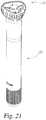
- cap assembly 20is securely attached to device 200 as shown in Fig. 21 as well as Figs. 1 and 2 .
- the cap assembly 20is simply removed from device 200, which pulls off the gripped rigid needle shield 210 and the inner shield 216 that the rigid needle shield holds.
Landscapes
- Health & Medical Sciences (AREA)
- Vascular Medicine (AREA)
- Engineering & Computer Science (AREA)
- Anesthesiology (AREA)
- Biomedical Technology (AREA)
- Heart & Thoracic Surgery (AREA)
- Hematology (AREA)
- Life Sciences & Earth Sciences (AREA)
- Animal Behavior & Ethology (AREA)
- General Health & Medical Sciences (AREA)
- Public Health (AREA)
- Veterinary Medicine (AREA)
- Infusion, Injection, And Reservoir Apparatuses (AREA)
- Measurement Of The Respiration, Hearing Ability, Form, And Blood Characteristics Of Living Organisms (AREA)
Description
- The present invention pertains to pharmaceutical injection devices, and, in particular, to a cap assembly for removing a rigid shield that protects a needle of a syringe.
- Many automatic injector devices include a cap feature which when removed from the device removes a protective shield from a needle of the syringe of the device. The protective shield may consist of a multipart construction including an inner shield and an outer shield which are operatively connected together. The inner shield is relatively flexible or elastomeric and provides a sterile barrier around the needle and forms a seal with, for example, the syringe hub from which the needle extends. The inner shield also may seal the tip of the needle such as in designs where the needle is already in fluid communication with the syringe contents. The outer shield is made of a relatively rigid material and protectively surrounds and engages the inner shield. A pulling of the outer or rigid needle shield from the syringe pulls off the inner shield as well.
- The cap feature of the device grips the rigid needle shield and serves to make easier the removal of the shield. The cap feature may be larger in diameter than the protective shield, or provided with a mechanical advantage to aid its removal, so as to be more readily grasped and removed by certain users than if the protective shield was removed alone. When the cap feature is removed from the device, which removal removes the protective shield as well due to the cap gripping the rigid needle shield, the needle is uncovered, although frequently still housed within the device prior to being extended therefrom during use, and ready for an injection.
- One known cap feature that grips a rigid needle shield utilizes a two-piece assembly. The first piece includes a plastic cup with a tubular portion designed to fit over a rigid needle shield portion of a protective shield previously mounted to an injection needle. The second piece includes a larger diameter, rigid plastic base cap having a softer, grippable periphery that may be provided via a comolding or two shot molding process. Two openings formed through sides of the tubular portion of the plastic cup define a pair of diametrically opposed grip fingers that are resilient so as to be deflectable. Each finger has an inner surface with serrated ribs, and an outer surface with a ramp formed thereon. After the plastic cup is placed onto the rigid needle shield such that the serrated ribs of the resilient fingers are in angular alignment with detents on the rigid needle shield with which they cooperate, the base cap is mounted to the plastic cup so that the tubular portion of the cup inserts into a cavity of the base cap. During this insertion, the base cap interior surface that defines its cavity engages the ramps of the grip fingers to deflect the fingers inward such that the serrated ribs come into gripping contact with the rigid needle shield. The base cap is so mounted until its radial protruding tabs within the base of the cavity snap fit into an annular recess on the exterior of the cup tubular portion, thereby locking the base cap and the plastic cup together to allow them to function as a unit.
- While such cap assemblies for removing rigid needle shields may provide a benefit to users, these cap assemblies may complicate the manufacture process. For example, mounting the cap assemblies requires a rotational orientation step to ensure the parts of the rigid needle shield and the cup which cooperate are angularly aligned. Such requires consideration during the manufacturing process, and if unsuccessfully performed may result in an unsatisfactory gripping of the rigid needle shield.
- Thus, it would be desirable to provide cap assembly that can overcome one or more of these and other shortcomings of the prior art.
- The two part form of claim 1 is based on
WO 2011/101379 A1 .WO 2011/101379 A1 discloses an auto-injector having a cap screwed onto to the proximal end of the auto-injector. The cap comprises a sheet metal clip with two or more barbs extending through an orifice into the proximal end of the auto-injector. The sheet metal clip is mounted to the cap for joint axial movement with respect to a longitudinal axis of the auto-injector. When the cap is screwed onto the proximal end of the auto-injector the barbs are pushed down a protective needle shield and snap into a circumferential notch arranged in the protective needle shield or behind a shoulder thereof. When a user wants to operate the auto-injector the first step is to unscrew the cap. Thus the barbs pull the protective needle shield off the syringe in a proximal direction making the syringe ready to be used. WO 2010/091522 A2 discloses an auto-injection apparatus for medical substances. It comprises a syringe for injecting the medical substance, a housing in which the syringe is at least partially accommodated in an axially fixed manner, a protective cap securely closing the syringe, and a pull-off aid for removing the protective cap. The protective cap is provided at least partially inside the housing and has at least one predetermined breaking point. The pull-off aid is connected to the protective cap such that an actuating movement of the pull-off air brings about a movement of the protective cap that is coupled to said movement, wherein the actuating movement of the pull-off aid can break the at least one predetermined breaking point and the pull-off aid can be removed with the protective cap fastened thereto from the syringe.WO 2012/164397 A1 discloses a cassette unit that is suitable for use with an auto-injector having an electrically powered drive unit. The cassette unit has a housing defining a cassette unit housing cavity and a needle projection aperture. The cassette unit housing cavity is arranged for receipt of a syringe that is suitable for use in the injected delivery of drug to a patient. The cassette unit includes a removable cap that in a capping position fits over and thereby, acts such as to close off, the needle projection aperture. The cassette unit includes a cap lock feature movable from a first cap locking position in which it prevents removal of the removable cap from the capping position with the cassette unit to a second cap non-locking position in which it no longer prevents such cap removal.WO 2009/040603 A1 discloses a device for automatic injection of a product into an injection site. The device comprises a needle and a needle shield for protection of the needle prior to use of said device, and a housing for receiving the container and a deshielder for removing the needle shield from the device. The deshielder is coupled to the needle shield and is mounted on the housing in a separable manner. The deshielder comprises tamper evidence means that are activated by the removal of at least one part of the deshielder.WO 2010/104779 A1 discloses a pharmaceutical delivery apparatus with an automatic syringe retraction following a manually controlled injection. The apparatus includes a housing, a syringe carriage, a medication-filled syringe held within the carriage, the syringe needle tip being disposed within the housing in a first position and projecting from the housing beyond the housing proximal end for insertion into an injection site in a second position, a manually shiftable plunger, means on the carriage and the housing and the plunger for causing the carriage to advance from the first position to the second position and for injecting medicine from the syringe when the plunger is manually plunged proximally toward the housing, and means on the carriage and the plunger for causing the carriage to retract from the second position to a position at which the needle tip is disposed within the housing when the plunger shifts distally.WO 2011/109205 A2 discloses an automatic injection apparatus including a delay mechanism for properly delivering medication prior to the needled syringe of the apparatus being retracted. In one form, the delay mechanism includes a shuttle for the syringe, a follower, a locking member, a damping compound between the follower and a supporting surface to dampen rotation of the follower relative to the shuttle, and a dual functioning biasing member acting between the shuttle and the follower. When the locking member moves to a release position during an injection, the dual functioning biasing member first provides a torsional force to force the follower to rotate relative to the shuttle from a latching position to an unlatching position, and then the dual functioning biasing member provides an axial force to force the shuttle axially relative to the follower to move the shuttle for retracting the syringe needle into the housing of the apparatus after injection.WO 2014/154498 A1, published on 2 October 2014 , and thus admissible at most under Article 54(3) EPC, discloses a front cap for a medicament delivery device having a proximal end and a distal end. The front cap is configured to be releasably connected to the medicament delivery device and comprises a shield grabber support and a shield grabber for connecting the front cap to an outer surface of a needle shield of a syringe positioned within the medicament delivery device. The shield grabber is coupled to the shield grabber support such that said shield grabber is axially moveable relative to the shield grabber support.- According to an aspect of the present invention there is provided the cap assembly of claim 1.
- Additional aspects of the invention are set out in the dependent claims.
- One advantage of the present invention is that a cap assembly may be provided which can be mounted to a rigid needle shield without the portion that directly engages the rigid needle shield being in a particular angular orientation.
- Another advantage of the present invention is that a cap assembly may be provided which can function within a range of axial tolerances at which the rigid needle shield can be presented for gripping.
- Another advantage of the present invention is that a cap assembly may be provided which, due to its gripping of a rigid needle shield at a point below a hole in a housing baseplate of a device through which a syringe needle extends, allows that hole in the housing baseplate to be made smaller than it would be if the cap assembly were to protrude into the hole.
- The above-mentioned and other advantages and objects of this invention, and the manner of attaining them, will become more apparent, and the invention itself will be better understood, by reference to the following description of embodiments of the invention taken in conjunction with the accompanying drawings, wherein:
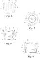
Fig. 1 is a front view of an automatic injection device equipped with a rigid needle shield gripping cap assembly of the present invention;Fig. 2 is a view of the device ofFig. 1 in partial longitudinal cross-section further revealing the cap assembly of the present invention;Fig. 3 is a top perspective view of only a completely manufactured gripper component of the cap assembly of the present invention in its neutral state;Fig. 4 is a bottom perspective view the gripper component ofFig. 3 ;Fig. 5 is a front view of the gripper component ofFig. 3 ;Fig. 6 is a side view of the gripper component ofFig. 3 ;Fig. 7 is a top view of the gripper component ofFig. 3 ;Fig. 8 is a longitudinal cross-sectional view of the gripper component taken along line 8-8 ofFig. 7 ;Fig. 9 is a longitudinal cross-sectional view of the gripper component taken along line 9-9 ofFig. 7 ;Fig. 10 is a bottom view of the gripper component ofFig. 3 ;Fig. 11 is a top view of the support frame of the gripper component ofFig. 3 prior to an elastomeric liner being overmolded thereto;Fig. 12 is a side view of the support frame ofFig. 11 ;Fig. 13 is a bottom view of the support frame ofFig. 11 ;Fig. 14 is a longitudinal cross-sectional view of the support frame taken along line 14-14 ofFig. 11 ;Fig. 15 is a longitudinal cross-sectional view of the support frame taken along line 15-15 ofFig. 11 ;Fig. 16 is a top perspective view of a completely manufactured base cap of the cap assembly of the present invention;Fig. 17 is a top view of the base cap ofFig. 16 ;Fig. 18 is a is a longitudinal cross-sectional view of the base cap taken along line 18-18 ofFig. 17 ;Fig. 19 is perspective view of a step in assembling the inventive cap assembly to a rigid needle shield of an automatic injection device;Fig. 20 is perspective view similar toFig. 19 at a subsequent step; andFig. 21 is perspective view similar toFig. 20 after the assembly is complete.- Corresponding reference characters indicate corresponding parts throughout the several views. Although the drawings represent an embodiment of the present invention, the drawings are not necessarily to scale, and certain features may be exaggerated or omitted in some of the drawings in order to better illustrate and explain the present invention.
- In
Figs. 1 and2 , a first embodiment of a cap assembly of the present invention, generally designated 20, is shown mounted to an automatic injection device, generally designated 200. Thecap assembly 20 is formed of an inner part or gripper component, generally designated 25, and an outer part or base cap, generally designated 30.Cap assembly 20 serves as a means for gripping a rigid needle shield to allow a user to conveniently remove a needle shield that protectively surrounds aneedle 220 of a syringe ofdevice 200 in order to prepare that device for use.Device 200 does not form a part of the present invention, but may be, for example, an automatic injection device as disclosed in PCT international patent application entitled "Trigger Assembly for an Automatic Injection Device", filed with the United States Patent and Trademark Office as Application No.PCT/US2013/064476 . - With additional reference to
Figs. 3-10 ,gripper component 25 is shown in its neutral or unstrained state prior to being used withbase cap 30 to grip a rigid needle shield.Gripper component 25 has a cup-like overall shape with aproximal end 32 and adistal end 34.Gripper component 25 is formed from a support frame, generally designated 40, and a liner, generally designated 80, which is comolded withframe 40 within its interior hollow 41. Support frame 40 is a single piece injection molded out of a relatively rigid and durable material such as glass filled polypropylene. As further shown inFigs. 11-15 ,support frame 40 includes a base formed of a pair of diametrically opposed, arc-shapedbase sections base sections groove 46 along its outer radial periphery. The opposite ends ofbase sections gaps 47.Gaps 47 allow thebase sections uncompressed support frame 40.Base section 42 also includes alobe 70 protruding radially at its distal end into thecircular opening 72 that would otherwise be generally defined bybase sections convex region 76 is formed inlobe 70 at the axial center of thegripper component 25.- Two pairs of
solid flanges 50 that are diametrically opposed from each other extend frombase sections apertured flanges 52 also extend frombase section solid flanges 50. Eachapertured flange 52 is defined by a tapering, interior opening orslot 54 and spans opposite ones of thegaps 47.Slots 54 can partially close whenbase sections gaps 47. - For the orientation of
gripper component 25 inFigs. 3-9 ,flanges Flanges proximal end 32 has a larger diametric extent than doesdistal end 34. Due to their plastic construction and their thinness in the radial direction,flanges - The end faces 58 of
flanges 50 includeupstanding tabs 60, and the end faces 64 ofapertured flanges 52 include similar but slightlylarger tabs 66.Tabs - With reference again to
Figs. 3-9 , theliner 80 is molded as part of a two shot molding process directly to thesupport frame 40 out of a material that is relatively resilient or compressible compared to the material of thesupport frame 40. One suitable material is a thermoplastic elastomer known as Santoprene®.Liner 80 can conform to and frictionally engage the outer radial periphery of the rigid needle shield that it is intended to grip. - The
overmolding liner 80 rings completely the inner radial periphery ofsupport frame 40 other than thelobe 70.Liner 80 is not only adhered via its comolding with the inner radial surfaces 82, 84 and 86 offlanges 50,flanges 52 andbase sections flanges Slots 54 andgaps 47 are not filled by theliner 80 so as to not prevent radial compression offlanges 52 andbase sections Liner 80 forms a substantially annular shape defining a central throughhole or bore 95. The linerinterior surface 97 that forms thebore 95 inward of theflanges interior surface 99 that forms thebore 95 inward of thebase sections bore 95 results in the proximal end of the bore being larger in diameter than the distal end of the bore, and this configuration, as well as the chamferedproximal end face 87 ofliner 80, can facilitate placement of thegripper component 25 over a rigid needle shield.- The tapering of the liner bore diameter results in an angled configuration relative to the axial direction that is less pronounced than the angle at which flanges 50, 52 splay outward such that
liner 80 has a radial thickness that is greater at the proximal end than at the distal end. - The
bore 95 ofliner 80 is dimensioned by the manufacturer in view of the rigid needle shield with whichcap assembly 20 will be used.Bore 95 along its axial length is typically slightly larger in diameter than the rigid needle shield such that thegripper component 25, when in its neutral or ready arrangement shown inFig. 3 , can be freely placed over that rigid needle shield, or in other words without any compression of theliner 80 being required. In such case thegripper component 25, before being engaged by thebase cap 30 during manufacturing assembly, could be removed easily from the rigid needle shield without potentially disturbing the rigid needle shield and the needle it surrounds. Thebore 95 may also be sufficiently smaller in diameter as to require a minimal amount of force againstliner 80 be provided by the rigid needle shield when inserted intobore 95, so long as assembly or removal of the gripper component, if such is desired to be done during manufacturing assembly before thebase cap 30 is attached, does not disturb the relationship of the needle and needle shield. - The
bore 95 ofliner 80 is also dimensioned by the manufacturer in view of the camming relationship of thegripper component 25 with thecap assembly 30, such thatliner 80, whencap assembly 30 is connected togripper component 25, is compressed around the rigid needle shield to provide a grip of the rigid needle shield sufficient for it to be able to pull the protective needle shield off the syringe needle when desired. - The cap
assembly base cap 30 is further shown inFigs. 16-18 .Base cap 30 is formed of a two shot molding having acentral body portion 100 and agripping periphery 102.Body portion 100 is formed of a rigid material such as polycarbonate.Periphery 102 is molded ontobody portion 100 out of a softer material, such as a thermoplastic elastomer such as Santoprene®, and includesknurling 104 to make it easier to grip anddirectional arrows 106 to show how it can be twisted for removal from the device. Body portion 100 includes acentral cavity 110 defined by a generallycylindrical surface region 112 with a chamfered lead-insurface 114.Surface region 112 is designed to fit around grippingcomponent 25 when placed thereover, but is sized and shaped to bend or cam inward theflanges Figs. 3-10 to a radially compressed, operational arrangement shown inFig. 2 to create a shield gripping configuration described further below. Three equally angularly spacedtangs 118 inwardly project withincavity 110 near its base. Rampedproximal faces 120 oftangs 118 aid intangs 118 inserting intogroove 46 during the connection ofbase cap 30 togripper component 25.- Three
cams 125 that are equally angularly spaced aroundcavity 110 and which are arcuate in shape project upwardly from theproximal surface 126 ofbody portion 100.Cams 125 fit withinarcuate slots 131 provided in thebase plate 130 of the device housing show inFig. 2 . Adetent 127 provided on each ofcams 125 engagesbase plate 130 to provide a releasable connection ofbody portion 100 to the base plate to aid in keepingcap assembly 20 ondevice 200 until its removal as desired. The camming engagement ofcams 125 withbase plate 130 when a user rotatescap assembly 20 relative to the rest ofdevice 200 in the direction ofarrows 106 shifts thecap assembly 20 away from the rest of the device, overcoming the connection ofdetents 127 with thebase plate 130, to facilitate cap removal. The removal of thecap assembly 20 fromdevice 200 may also be done without rotation of the cap assembly but merely by the user pulling it axially. - The structure of
cap assembly 20 will be further understood in view of the following description of its assembly to a device by a manufacturer. InFig. 19 ,injection device 200 is shown prepared for the attachment ofcap assembly 20 to therigid needle shield 210 of the device shown projecting beyondbase plate 130. The inventive cap assembly can engage rigid needle shields of various shapes known in the art, including those which lack recesses or protrusions thatliner 80 can fit into or around. The shownrigid needle shield 210 has a generally cylindrical, projectingend region 212 withlongitudinal slots 214 spaced around the circumference through which an elastomericinner shield 216 is visible.Inner shield 216 seals the end of aneedle 220 of asyringe 222 withindevice 200 as further shown inFig. 2 .Rigid needle shield 210 andinner shield 216 are interconnected at 217 so that the protective shield they provide together around the end ofneedle 220 is removable as a unit. - Assembly of the
cap assembly 20 torigid needle shield 210 begins with maneuvering agripper component 25, in its neutral state, into a position axially above therigid needle shield 210 as shown inFig. 19 , and then moving it down as indicated byarrow 230 such thatrigid needle shield 210 inserts into liner bore 95. This insertion ends when the flange offsets 60, 66 abut thebase plate 130. While alternatively this insertion could end when the tip ofrigid needle shield 210 abutslobe 70, such is less desired as this transmits forces to the needle shield.Gripper component 25 advantageously need not be in any particular rotational orientation relative to shield 210. Base cap 30 is then brought into a position axially above thegripper component 25 resting over therigid needle shield 210, and moved down as indicated byarrow 235 inFig. 20 such that thegripper component 25 inserts withincavity 110 ofbase cap 30. Initially during this insertion, no resistance is met as the base ofgripper component 25 first freely inserts withincavity 110. As the insertion continues, however,cavity surface 112 at chamfered lead-insurface 114 encounters the outer radial peripheries first ofbase sections cavity 110. The downward axial movement ofbase cap 30 causes basesections flanges surface 112, and this camming forcesliner 80 against therigid needle shield 210 so as to be sandwiched betweenshield 210 andflanges shield 210 and boresurface 112 in the angular spaces between the flanges. When so sandwiched,liner 80 conforms to the periphery of therigid needle shield 210 to provide a tight grip thereof. The insertion ofgripper component 25 is halted after thebase cap tangs 118 snap fit intogroove 46 ofbase sections base cap 30 andgripper component 25 are locked together to allow them to function as a unit for shield removal purposes. Frictional forces betweensurface 112 and the outer periphery of theflanges base cap 30, but need not so act within the scope of the invention. At this point,cap assembly 20 is securely attached todevice 200 as shown inFig. 21 as well asFigs. 1 and2 . When the device needle is to have its protective shield removed for use, thecap assembly 20 is simply removed fromdevice 200, which pulls off the grippedrigid needle shield 210 and theinner shield 216 that the rigid needle shield holds.- While this invention has been shown and described as having preferred designs, the present invention may be modified within the scope of the claims. For example, while the liner is described as being overmolded to the support frame as a two part process, the liner could be separately formed and then securely attached to the support frame. This application is therefore intended to cover any variations, uses or adaptations of the invention using its general principles. Further, this application is intended to cover such departures from the present disclosure as come within known or customary practice in the art to which this invention pertains.
Claims (8)
- A cap assembly (20) mountable to a rigid shield (210) around a needle (220) of a syringe (222), said cap assembly comprising:a gripper component (25) for directly engaging the rigid shield; anda base cap (30) grippable by a user and comprising a body (100), said body including a surface (112) defining a cavity (110) for accommodating said gripper component;characterized by:said gripper component including a support frame (40) and a liner (80), said support frame defining an interior hollow (41), said liner secured to said support frame within said interior hollow to provide a gripping section (97) that defines a bore (95) sized to axially receive the rigid shield, said liner formed of a material that is resilient relative to a material forming said support frame and is deformable when sandwiched between said support frame and the rigid shield;said support frame (40) comprising a base section (42, 44) and a plurality of resilient flanges (50, 52) integrally formed with and extending from said base section, said plurality of flanges in a neutral state splaying radially outward from said base section; andsaid body surface being sized and shaped to bend or cam inward said plurality of resilient flanges to compress said gripper component from a first arrangement to a second arrangement when said gripper component inserts within said cavity during manufacture, wherein said liner, when said gripper component is disposed in said first arrangement, does not grip for shield removal purposes the rigid shield when disposed in said bore, and wherein said liner, when said gripper component is disposed in said second arrangement with the rigid shield disposed in said bore in any rotational orientation relative thereto, is held by the support frame so as to be deformed against and grip the rigid shield for shield removal purposes so as to allow for removal of the rigid shield from around the needle.
- The cap assembly of Claim 1 wherein said support frame base section (42, 44) comprises a plurality of arc shaped members having ends which are angularly spaced to provide gaps (47).
- The cap assembly of Claim 2 wherein said flanges include apertured flanges (52) that span said gaps (47).
- The cap assembly of any one of the preceding claims wherein said liner (80) is comolded with said support frame (40).
- The cap assembly of any one of the preceding claims wherein said gripping section (97) is annular in shape.
- The cap assembly of Claim 5 wherein said gripping section (97) is adapted to grip an entire circumference of the rigid shield (210) at a common axial position of the rigid shield.
- The cap assembly of Claim 5 or Claim 6 wherein said annular gripping section (97) tapers in the radial direction as it extends axially toward a base of said cavity (110).
- The cap assembly of any one of the preceding claims wherein said gripper component (25) is adapted to directly engage the rigid shield (210) at a point of the rigid shield which projects prior to use beyond a housing of a device holding a syringe (222) on which the rigid shield is mounted.
Applications Claiming Priority (2)
| Application Number | Priority Date | Filing Date | Title |
|---|---|---|---|
| US201461938219P | 2014-02-11 | 2014-02-11 | |
| PCT/US2015/014733WO2015123096A1 (en) | 2014-02-11 | 2015-02-06 | Rigid needle shield gripping cap assembly |
Publications (2)
| Publication Number | Publication Date |
|---|---|
| EP3104914A1 EP3104914A1 (en) | 2016-12-21 |
| EP3104914B1true EP3104914B1 (en) | 2019-10-02 |
Family
ID=52472640
Family Applications (1)
| Application Number | Title | Priority Date | Filing Date |
|---|---|---|---|
| EP15704685.5AActiveEP3104914B1 (en) | 2014-02-11 | 2015-02-06 | Rigid needle shield gripping cap assembly |
Country Status (13)
| Country | Link |
|---|---|
| US (1) | US10118001B2 (en) |
| EP (1) | EP3104914B1 (en) |
| JP (1) | JP6310566B2 (en) |
| KR (1) | KR101861460B1 (en) |
| CN (1) | CN105960257B (en) |
| AU (1) | AU2015217443B2 (en) |
| CA (1) | CA2936637C (en) |
| EA (1) | EA201691419A1 (en) |
| ES (1) | ES2759237T3 (en) |
| HK (1) | HK1226341A1 (en) |
| MX (1) | MX2016010484A (en) |
| WO (1) | WO2015123096A1 (en) |
| ZA (1) | ZA201604596B (en) |
Families Citing this family (27)
| Publication number | Priority date | Publication date | Assignee | Title |
|---|---|---|---|---|
| DK2536452T3 (en) | 2010-02-18 | 2019-01-02 | Sanofi Aventis Deutschland | autoinjector |
| EP2399635A1 (en) | 2010-06-28 | 2011-12-28 | Sanofi-Aventis Deutschland GmbH | Auto-injector |
| EP2468330A1 (en) | 2010-12-21 | 2012-06-27 | Sanofi-Aventis Deutschland GmbH | Auto-injector |
| EP2489385A1 (en) | 2011-02-18 | 2012-08-22 | Sanofi-Aventis Deutschland GmbH | Auto-injector |
| EP2572741A1 (en) | 2011-09-23 | 2013-03-27 | Sanofi-Aventis Deutschland GmbH | Medicament delivery device and actuation mechanism for a drug delivery device |
| EP2719414A1 (en) | 2012-10-15 | 2014-04-16 | Sanofi-Aventis Deutschland GmbH | Medicament delivery device with use indicator |
| EP2777684A1 (en) | 2013-03-14 | 2014-09-17 | Sanofi-Aventis Deutschland GmbH | Medicament container carrier and adapter |
| PL3226944T5 (en) | 2014-12-03 | 2023-01-30 | Eli Lilly And Company | Needle shield puller cap assembly |
| TW201700118A (en) | 2015-06-03 | 2017-01-01 | 賽諾菲阿凡提斯德意志有限公司 | Drug delivery device (3) |
| USD810282S1 (en)* | 2015-10-19 | 2018-02-13 | Carebay Europe Ltd | Medical injector |
| US10092707B2 (en) | 2015-12-08 | 2018-10-09 | Becton Dickinson France S.A.S. | T-shaped cap for medical injector |
| KR102751238B1 (en) | 2015-12-08 | 2025-01-07 | 벡톤 디킨슨 프랑스 | medical injector cap |
| US10737036B2 (en) | 2015-12-08 | 2020-08-11 | Becton Dickinson France S.A.S. | Housing and cap for medical injector |
| EP3386572B1 (en)* | 2015-12-08 | 2024-12-04 | Becton Dickinson France | Cap with hemisphere portion for medical injector |
| US10661024B2 (en)* | 2016-03-23 | 2020-05-26 | West Pharmaceutical Services, Inc. | Two piece needle shield puller |
| CH712753A2 (en) | 2016-07-28 | 2018-01-31 | Tecpharma Licensing Ag | Separating a needle cap from a product container and method of mounting an injection device. |
| CN115715676B (en) | 2017-06-08 | 2025-09-16 | 贝克顿·迪金森公司 | Biological fluid separation device |
| US11452821B2 (en) | 2017-10-12 | 2022-09-27 | Eli Lilly And Company | Needle shield puller for drug delivery system |
| CA3132163A1 (en) | 2019-03-15 | 2020-09-24 | Eli Lilly And Company | Automatic injection system |
| USD1097146S1 (en)* | 2023-05-03 | 2025-10-07 | Matthew John Petrides | Syringe cap |
| US12357758B1 (en) | 2024-04-19 | 2025-07-15 | Genzyme Corporation | Medicament delivery device |
| US12343511B1 (en) | 2024-04-19 | 2025-07-01 | Genzyme Corporation | Medicament delivery device |
| US12337160B1 (en) | 2024-04-19 | 2025-06-24 | Genzyme Corporation | Medicament delivery device |
| US12377226B1 (en) | 2024-04-19 | 2025-08-05 | Genzyme Corporation | Medicament delivery device |
| US12343505B1 (en) | 2024-04-19 | 2025-07-01 | Genzyme Corporation | Medicament delivery device |
| US12434008B1 (en) | 2025-02-26 | 2025-10-07 | Genzyme Corporation | Lock ring for a medicament delivery device |
| US12420017B1 (en) | 2025-02-26 | 2025-09-23 | Genzyme Corporation | Damping device for a medicament delivery device |
Family Cites Families (14)
| Publication number | Priority date | Publication date | Assignee | Title |
|---|---|---|---|---|
| GB9506087D0 (en)* | 1995-03-24 | 1995-05-10 | Owen Mumford Ltd | Improvements relating to medical injection devices |
| DE60218296T2 (en) | 2001-03-27 | 2007-07-12 | Eli Lilly And Co., Indianapolis | KIT WITH A SYRINGE PAD WITH SIDE OPENING FOR PREPARING A MEDICAMENT IN AN INJECTION PEN CARTRIDGE |
| WO2007047200A1 (en) | 2005-10-11 | 2007-04-26 | Eli Lilly And Company | Apparatus for injecting a pharmaceutical |
| JP5362591B2 (en) | 2007-03-09 | 2013-12-11 | イーライ リリー アンド カンパニー | Delay mechanism for automatic injection equipment |
| WO2009040603A1 (en)* | 2007-09-25 | 2009-04-02 | Becton Dickinson France | Autoinjector with deshielder comprising tamper evidence means |
| DE102009008754A1 (en) | 2009-02-12 | 2010-08-26 | Tecpharma Licensing Ag | Administration device, in particular autoinjection device, for a medical substance with a withdrawal aid for a protective cap |
| KR101366427B1 (en)* | 2009-03-13 | 2014-02-24 | 일라이 릴리 앤드 캄파니 | Apparatus for injecting a pharmaceutical with automatic syringe retraction following injection |
| EP2440270B1 (en)* | 2009-06-12 | 2013-04-24 | Novo Nordisk A/S | Drug delivery device with cap functions for needle assembly |
| DK2536452T3 (en)* | 2010-02-18 | 2019-01-02 | Sanofi Aventis Deutschland | autoinjector |
| ES2484266T3 (en) | 2010-03-01 | 2014-08-11 | Eli Lilly And Company | Automatic injection device with delay mechanism including a double function thrust element |
| ES2710905T3 (en) | 2011-01-24 | 2019-04-29 | E3D Agricultural Coop Association Ltd | Injector |
| WO2012164389A2 (en)* | 2011-06-02 | 2012-12-06 | Ucb Pharma S.A. | Auto-injector |
| ES2661932T5 (en)* | 2011-07-05 | 2024-04-23 | Shl Medical Ag | Needle sheath removal element assembly |
| WO2014154498A1 (en)* | 2013-03-25 | 2014-10-02 | Carebay Europe Ltd | Front cap for a medicament delivery device |
- 2015
- 2015-02-06EAEA201691419Apatent/EA201691419A1/enunknown
- 2015-02-06ESES15704685Tpatent/ES2759237T3/enactiveActive
- 2015-02-06MXMX2016010484Apatent/MX2016010484A/enunknown
- 2015-02-06JPJP2016551205Apatent/JP6310566B2/enactiveActive
- 2015-02-06AUAU2015217443Apatent/AU2015217443B2/ennot_activeCeased
- 2015-02-06USUS15/114,873patent/US10118001B2/enactiveActive
- 2015-02-06WOPCT/US2015/014733patent/WO2015123096A1/enactiveApplication Filing
- 2015-02-06KRKR1020167021633Apatent/KR101861460B1/ennot_activeExpired - Fee Related
- 2015-02-06EPEP15704685.5Apatent/EP3104914B1/enactiveActive
- 2015-02-06CACA2936637Apatent/CA2936637C/enactiveActive
- 2015-02-06HKHK16114570.1Apatent/HK1226341A1/enunknown
- 2015-02-06CNCN201580008221.6Apatent/CN105960257B/enactiveActive
- 2016
- 2016-07-06ZAZA2016/04596Apatent/ZA201604596B/enunknown
Non-Patent Citations (1)
| Title |
|---|
| None* |
Also Published As
| Publication number | Publication date |
|---|---|
| CA2936637C (en) | 2018-11-27 |
| KR101861460B1 (en) | 2018-05-28 |
| EA201691419A1 (en) | 2016-11-30 |
| JP2017505675A (en) | 2017-02-23 |
| MX2016010484A (en) | 2016-10-17 |
| AU2015217443B2 (en) | 2017-05-11 |
| ES2759237T3 (en) | 2020-05-08 |
| EP3104914A1 (en) | 2016-12-21 |
| US10118001B2 (en) | 2018-11-06 |
| CA2936637A1 (en) | 2015-08-20 |
| CN105960257A (en) | 2016-09-21 |
| US20170259008A1 (en) | 2017-09-14 |
| KR20160106162A (en) | 2016-09-09 |
| HK1226341A1 (en) | 2017-09-29 |
| JP6310566B2 (en) | 2018-04-11 |
| AU2015217443A1 (en) | 2016-07-14 |
| CN105960257B (en) | 2019-04-19 |
| ZA201604596B (en) | 2019-04-24 |
| WO2015123096A1 (en) | 2015-08-20 |
Similar Documents
| Publication | Publication Date | Title |
|---|---|---|
| EP3104914B1 (en) | Rigid needle shield gripping cap assembly | |
| US10881795B2 (en) | Auto-injector device | |
| US10751482B2 (en) | Pen needle tip | |
| CN209848029U (en) | Pen needle | |
| EP3226944B2 (en) | Needle shield puller cap assembly | |
| AU2008240105B2 (en) | Safety syringe | |
| EP1888147B1 (en) | Injection device | |
| US6361525B2 (en) | Single-use syringe | |
| CN109310821B (en) | Container holder assembly | |
| US10881797B2 (en) | Drive mechanism for an autoinjector | |
| CN102770173A (en) | Automatic injection device with delay mechanism including dual function biasing member | |
| GB2465389A (en) | Syringe needle cover remover | |
| US11524123B2 (en) | Safety assembly and medical device with safety assembly | |
| CN109475701B (en) | Medication Container Assembly for Medication Delivery Device |
Legal Events
| Date | Code | Title | Description |
|---|---|---|---|
| PUAI | Public reference made under article 153(3) epc to a published international application that has entered the european phase | Free format text:ORIGINAL CODE: 0009012 | |
| STAA | Information on the status of an ep patent application or granted ep patent | Free format text:STATUS: REQUEST FOR EXAMINATION WAS MADE | |
| 17P | Request for examination filed | Effective date:20160701 | |
| AK | Designated contracting states | Kind code of ref document:A1 Designated state(s):AL AT BE BG CH CY CZ DE DK EE ES FI FR GB GR HR HU IE IS IT LI LT LU LV MC MK MT NL NO PL PT RO RS SE SI SK SM TR | |
| AX | Request for extension of the european patent | Extension state:BA ME | |
| REG | Reference to a national code | Ref country code:HK Ref legal event code:DE Ref document number:1226341 Country of ref document:HK | |
| GRAP | Despatch of communication of intention to grant a patent | Free format text:ORIGINAL CODE: EPIDOSNIGR1 | |
| STAA | Information on the status of an ep patent application or granted ep patent | Free format text:STATUS: GRANT OF PATENT IS INTENDED | |
| INTG | Intention to grant announced | Effective date:20190418 | |
| GRAS | Grant fee paid | Free format text:ORIGINAL CODE: EPIDOSNIGR3 | |
| GRAA | (expected) grant | Free format text:ORIGINAL CODE: 0009210 | |
| STAA | Information on the status of an ep patent application or granted ep patent | Free format text:STATUS: THE PATENT HAS BEEN GRANTED | |
| AK | Designated contracting states | Kind code of ref document:B1 Designated state(s):AL AT BE BG CH CY CZ DE DK EE ES FI FR GB GR HR HU IE IS IT LI LT LU LV MC MK MT NL NO PL PT RO RS SE SI SK SM TR | |
| AX | Request for extension of the european patent | Extension state:BA ME | |
| REG | Reference to a national code | Ref country code:GB Ref legal event code:FG4D | |
| REG | Reference to a national code | Ref country code:AT Ref legal event code:REF Ref document number:1185510 Country of ref document:AT Kind code of ref document:T Effective date:20191015 Ref country code:CH Ref legal event code:EP | |
| REG | Reference to a national code | Ref country code:DE Ref legal event code:R096 Ref document number:602015039000 Country of ref document:DE | |
| REG | Reference to a national code | Ref country code:IE Ref legal event code:FG4D | |
| REG | Reference to a national code | Ref country code:NL Ref legal event code:MP Effective date:20191002 | |
| REG | Reference to a national code | Ref country code:LT Ref legal event code:MG4D | |
| REG | Reference to a national code | Ref country code:AT Ref legal event code:MK05 Ref document number:1185510 Country of ref document:AT Kind code of ref document:T Effective date:20191002 | |
| PG25 | Lapsed in a contracting state [announced via postgrant information from national office to epo] | Ref country code:LT Free format text:LAPSE BECAUSE OF FAILURE TO SUBMIT A TRANSLATION OF THE DESCRIPTION OR TO PAY THE FEE WITHIN THE PRESCRIBED TIME-LIMIT Effective date:20191002 Ref country code:PL Free format text:LAPSE BECAUSE OF FAILURE TO SUBMIT A TRANSLATION OF THE DESCRIPTION OR TO PAY THE FEE WITHIN THE PRESCRIBED TIME-LIMIT Effective date:20191002 Ref country code:GR Free format text:LAPSE BECAUSE OF FAILURE TO SUBMIT A TRANSLATION OF THE DESCRIPTION OR TO PAY THE FEE WITHIN THE PRESCRIBED TIME-LIMIT Effective date:20200103 Ref country code:NO Free format text:LAPSE BECAUSE OF FAILURE TO SUBMIT A TRANSLATION OF THE DESCRIPTION OR TO PAY THE FEE WITHIN THE PRESCRIBED TIME-LIMIT Effective date:20200102 Ref country code:PT Free format text:LAPSE BECAUSE OF FAILURE TO SUBMIT A TRANSLATION OF THE DESCRIPTION OR TO PAY THE FEE WITHIN THE PRESCRIBED TIME-LIMIT Effective date:20200203 Ref country code:FI Free format text:LAPSE BECAUSE OF FAILURE TO SUBMIT A TRANSLATION OF THE DESCRIPTION OR TO PAY THE FEE WITHIN THE PRESCRIBED TIME-LIMIT Effective date:20191002 Ref country code:BG Free format text:LAPSE BECAUSE OF FAILURE TO SUBMIT A TRANSLATION OF THE DESCRIPTION OR TO PAY THE FEE WITHIN THE PRESCRIBED TIME-LIMIT Effective date:20200102 Ref country code:AT Free format text:LAPSE BECAUSE OF FAILURE TO SUBMIT A TRANSLATION OF THE DESCRIPTION OR TO PAY THE FEE WITHIN THE PRESCRIBED TIME-LIMIT Effective date:20191002 Ref country code:NL Free format text:LAPSE BECAUSE OF FAILURE TO SUBMIT A TRANSLATION OF THE DESCRIPTION OR TO PAY THE FEE WITHIN THE PRESCRIBED TIME-LIMIT Effective date:20191002 Ref country code:LV Free format text:LAPSE BECAUSE OF FAILURE TO SUBMIT A TRANSLATION OF THE DESCRIPTION OR TO PAY THE FEE WITHIN THE PRESCRIBED TIME-LIMIT Effective date:20191002 Ref country code:SE Free format text:LAPSE BECAUSE OF FAILURE TO SUBMIT A TRANSLATION OF THE DESCRIPTION OR TO PAY THE FEE WITHIN THE PRESCRIBED TIME-LIMIT Effective date:20191002 | |
| REG | Reference to a national code | Ref country code:ES Ref legal event code:FG2A Ref document number:2759237 Country of ref document:ES Kind code of ref document:T3 Effective date:20200508 | |
| PG25 | Lapsed in a contracting state [announced via postgrant information from national office to epo] | Ref country code:IS Free format text:LAPSE BECAUSE OF FAILURE TO SUBMIT A TRANSLATION OF THE DESCRIPTION OR TO PAY THE FEE WITHIN THE PRESCRIBED TIME-LIMIT Effective date:20200224 Ref country code:CZ Free format text:LAPSE BECAUSE OF FAILURE TO SUBMIT A TRANSLATION OF THE DESCRIPTION OR TO PAY THE FEE WITHIN THE PRESCRIBED TIME-LIMIT Effective date:20191002 Ref country code:HR Free format text:LAPSE BECAUSE OF FAILURE TO SUBMIT A TRANSLATION OF THE DESCRIPTION OR TO PAY THE FEE WITHIN THE PRESCRIBED TIME-LIMIT Effective date:20191002 Ref country code:RS Free format text:LAPSE BECAUSE OF FAILURE TO SUBMIT A TRANSLATION OF THE DESCRIPTION OR TO PAY THE FEE WITHIN THE PRESCRIBED TIME-LIMIT Effective date:20191002 | |
| PG25 | Lapsed in a contracting state [announced via postgrant information from national office to epo] | Ref country code:AL Free format text:LAPSE BECAUSE OF FAILURE TO SUBMIT A TRANSLATION OF THE DESCRIPTION OR TO PAY THE FEE WITHIN THE PRESCRIBED TIME-LIMIT Effective date:20191002 | |
| REG | Reference to a national code | Ref country code:DE Ref legal event code:R097 Ref document number:602015039000 Country of ref document:DE | |
| PG2D | Information on lapse in contracting state deleted | Ref country code:IS | |
| PG25 | Lapsed in a contracting state [announced via postgrant information from national office to epo] | Ref country code:IS Free format text:LAPSE BECAUSE OF FAILURE TO SUBMIT A TRANSLATION OF THE DESCRIPTION OR TO PAY THE FEE WITHIN THE PRESCRIBED TIME-LIMIT Effective date:20200202 Ref country code:EE Free format text:LAPSE BECAUSE OF FAILURE TO SUBMIT A TRANSLATION OF THE DESCRIPTION OR TO PAY THE FEE WITHIN THE PRESCRIBED TIME-LIMIT Effective date:20191002 Ref country code:DK Free format text:LAPSE BECAUSE OF FAILURE TO SUBMIT A TRANSLATION OF THE DESCRIPTION OR TO PAY THE FEE WITHIN THE PRESCRIBED TIME-LIMIT Effective date:20191002 Ref country code:RO Free format text:LAPSE BECAUSE OF FAILURE TO SUBMIT A TRANSLATION OF THE DESCRIPTION OR TO PAY THE FEE WITHIN THE PRESCRIBED TIME-LIMIT Effective date:20191002 | |
| PLBE | No opposition filed within time limit | Free format text:ORIGINAL CODE: 0009261 | |
| STAA | Information on the status of an ep patent application or granted ep patent | Free format text:STATUS: NO OPPOSITION FILED WITHIN TIME LIMIT | |
| PG25 | Lapsed in a contracting state [announced via postgrant information from national office to epo] | Ref country code:SM Free format text:LAPSE BECAUSE OF FAILURE TO SUBMIT A TRANSLATION OF THE DESCRIPTION OR TO PAY THE FEE WITHIN THE PRESCRIBED TIME-LIMIT Effective date:20191002 Ref country code:SK Free format text:LAPSE BECAUSE OF FAILURE TO SUBMIT A TRANSLATION OF THE DESCRIPTION OR TO PAY THE FEE WITHIN THE PRESCRIBED TIME-LIMIT Effective date:20191002 | |
| 26N | No opposition filed | Effective date:20200703 | |
| REG | Reference to a national code | Ref country code:CH Ref legal event code:PL | |
| REG | Reference to a national code | Ref country code:BE Ref legal event code:MM Effective date:20200229 | |
| PG25 | Lapsed in a contracting state [announced via postgrant information from national office to epo] | Ref country code:LU Free format text:LAPSE BECAUSE OF NON-PAYMENT OF DUE FEES Effective date:20200206 Ref country code:MC Free format text:LAPSE BECAUSE OF FAILURE TO SUBMIT A TRANSLATION OF THE DESCRIPTION OR TO PAY THE FEE WITHIN THE PRESCRIBED TIME-LIMIT Effective date:20191002 | |
| PG25 | Lapsed in a contracting state [announced via postgrant information from national office to epo] | Ref country code:CH Free format text:LAPSE BECAUSE OF NON-PAYMENT OF DUE FEES Effective date:20200229 Ref country code:LI Free format text:LAPSE BECAUSE OF NON-PAYMENT OF DUE FEES Effective date:20200229 Ref country code:SI Free format text:LAPSE BECAUSE OF FAILURE TO SUBMIT A TRANSLATION OF THE DESCRIPTION OR TO PAY THE FEE WITHIN THE PRESCRIBED TIME-LIMIT Effective date:20191002 | |
| PG25 | Lapsed in a contracting state [announced via postgrant information from national office to epo] | Ref country code:IE Free format text:LAPSE BECAUSE OF NON-PAYMENT OF DUE FEES Effective date:20200206 | |
| PG25 | Lapsed in a contracting state [announced via postgrant information from national office to epo] | Ref country code:BE Free format text:LAPSE BECAUSE OF NON-PAYMENT OF DUE FEES Effective date:20200229 | |
| PG25 | Lapsed in a contracting state [announced via postgrant information from national office to epo] | Ref country code:TR Free format text:LAPSE BECAUSE OF FAILURE TO SUBMIT A TRANSLATION OF THE DESCRIPTION OR TO PAY THE FEE WITHIN THE PRESCRIBED TIME-LIMIT Effective date:20191002 Ref country code:MT Free format text:LAPSE BECAUSE OF FAILURE TO SUBMIT A TRANSLATION OF THE DESCRIPTION OR TO PAY THE FEE WITHIN THE PRESCRIBED TIME-LIMIT Effective date:20191002 Ref country code:CY Free format text:LAPSE BECAUSE OF FAILURE TO SUBMIT A TRANSLATION OF THE DESCRIPTION OR TO PAY THE FEE WITHIN THE PRESCRIBED TIME-LIMIT Effective date:20191002 | |
| PG25 | Lapsed in a contracting state [announced via postgrant information from national office to epo] | Ref country code:MK Free format text:LAPSE BECAUSE OF FAILURE TO SUBMIT A TRANSLATION OF THE DESCRIPTION OR TO PAY THE FEE WITHIN THE PRESCRIBED TIME-LIMIT Effective date:20191002 | |
| P01 | Opt-out of the competence of the unified patent court (upc) registered | Effective date:20230417 | |
| REG | Reference to a national code | Ref country code:HK Ref legal event code:WD Ref document number:1226341 Country of ref document:HK | |
| PGFP | Annual fee paid to national office [announced via postgrant information from national office to epo] | Ref country code:DE Payment date:20250122 Year of fee payment:11 | |
| PGFP | Annual fee paid to national office [announced via postgrant information from national office to epo] | Ref country code:ES Payment date:20250303 Year of fee payment:11 | |
| PGFP | Annual fee paid to national office [announced via postgrant information from national office to epo] | Ref country code:FR Payment date:20250122 Year of fee payment:11 | |
| PGFP | Annual fee paid to national office [announced via postgrant information from national office to epo] | Ref country code:IT Payment date:20250121 Year of fee payment:11 Ref country code:GB Payment date:20250123 Year of fee payment:11 |