EP3104671B1 - Methods and systems for magnetic coupling - Google Patents
Methods and systems for magnetic couplingDownload PDFInfo
- Publication number
- EP3104671B1 EP3104671B1EP16167926.1AEP16167926AEP3104671B1EP 3104671 B1EP3104671 B1EP 3104671B1EP 16167926 AEP16167926 AEP 16167926AEP 3104671 B1EP3104671 B1EP 3104671B1
- Authority
- EP
- European Patent Office
- Prior art keywords
- connector
- circuit board
- printed circuit
- contact pad
- magnet
- Prior art date
- Legal status (The legal status is an assumption and is not a legal conclusion. Google has not performed a legal analysis and makes no representation as to the accuracy of the status listed.)
- Active
Links
Images


Classifications
- H—ELECTRICITY
- H01—ELECTRIC ELEMENTS
- H01R—ELECTRICALLY-CONDUCTIVE CONNECTIONS; STRUCTURAL ASSOCIATIONS OF A PLURALITY OF MUTUALLY-INSULATED ELECTRICAL CONNECTING ELEMENTS; COUPLING DEVICES; CURRENT COLLECTORS
- H01R13/00—Details of coupling devices of the kinds covered by groups H01R12/70 or H01R24/00 - H01R33/00
- H01R13/62—Means for facilitating engagement or disengagement of coupling parts or for holding them in engagement
- H01R13/6205—Two-part coupling devices held in engagement by a magnet
- G—PHYSICS
- G06—COMPUTING OR CALCULATING; COUNTING
- G06F—ELECTRIC DIGITAL DATA PROCESSING
- G06F1/00—Details not covered by groups G06F3/00 - G06F13/00 and G06F21/00
- G06F1/16—Constructional details or arrangements
- H—ELECTRICITY
- H01—ELECTRIC ELEMENTS
- H01R—ELECTRICALLY-CONDUCTIVE CONNECTIONS; STRUCTURAL ASSOCIATIONS OF A PLURALITY OF MUTUALLY-INSULATED ELECTRICAL CONNECTING ELEMENTS; COUPLING DEVICES; CURRENT COLLECTORS
- H01R13/00—Details of coupling devices of the kinds covered by groups H01R12/70 or H01R24/00 - H01R33/00
- H01R13/66—Structural association with built-in electrical component
- H01R13/665—Structural association with built-in electrical component with built-in electronic circuit
- H01R13/6658—Structural association with built-in electrical component with built-in electronic circuit on printed circuit board
- H—ELECTRICITY
- H05—ELECTRIC TECHNIQUES NOT OTHERWISE PROVIDED FOR
- H05K—PRINTED CIRCUITS; CASINGS OR CONSTRUCTIONAL DETAILS OF ELECTRIC APPARATUS; MANUFACTURE OF ASSEMBLAGES OF ELECTRICAL COMPONENTS
- H05K1/00—Printed circuits
- H05K1/02—Details
- H05K1/11—Printed elements for providing electric connections to or between printed circuits
- H—ELECTRICITY
- H05—ELECTRIC TECHNIQUES NOT OTHERWISE PROVIDED FOR
- H05K—PRINTED CIRCUITS; CASINGS OR CONSTRUCTIONAL DETAILS OF ELECTRIC APPARATUS; MANUFACTURE OF ASSEMBLAGES OF ELECTRICAL COMPONENTS
- H05K5/00—Casings, cabinets or drawers for electric apparatus
- H05K5/02—Details
- H05K5/0256—Details of interchangeable modules or receptacles therefor, e.g. cartridge mechanisms
- H05K5/026—Details of interchangeable modules or receptacles therefor, e.g. cartridge mechanisms having standardized interfaces
- H05K5/0278—Details of interchangeable modules or receptacles therefor, e.g. cartridge mechanisms having standardized interfaces of USB type
- H—ELECTRICITY
- H01—ELECTRIC ELEMENTS
- H01R—ELECTRICALLY-CONDUCTIVE CONNECTIONS; STRUCTURAL ASSOCIATIONS OF A PLURALITY OF MUTUALLY-INSULATED ELECTRICAL CONNECTING ELEMENTS; COUPLING DEVICES; CURRENT COLLECTORS
- H01R11/00—Individual connecting elements providing two or more spaced connecting locations for conductive members which are, or may be, thereby interconnected, e.g. end pieces for wires or cables supported by the wire or cable and having means for facilitating electrical connection to some other wire, terminal, or conductive member, blocks of binding posts
- H01R11/11—End pieces or tapping pieces for wires, supported by the wire and for facilitating electrical connection to some other wire, terminal or conductive member
- H01R11/22—End pieces terminating in a spring clip
- H01R11/24—End pieces terminating in a spring clip with gripping jaws, e.g. crocodile clip
- H—ELECTRICITY
- H01—ELECTRIC ELEMENTS
- H01R—ELECTRICALLY-CONDUCTIVE CONNECTIONS; STRUCTURAL ASSOCIATIONS OF A PLURALITY OF MUTUALLY-INSULATED ELECTRICAL CONNECTING ELEMENTS; COUPLING DEVICES; CURRENT COLLECTORS
- H01R2201/00—Connectors or connections adapted for particular applications
- H01R2201/06—Connectors or connections adapted for particular applications for computer periphery
- H—ELECTRICITY
- H05—ELECTRIC TECHNIQUES NOT OTHERWISE PROVIDED FOR
- H05K—PRINTED CIRCUITS; CASINGS OR CONSTRUCTIONAL DETAILS OF ELECTRIC APPARATUS; MANUFACTURE OF ASSEMBLAGES OF ELECTRICAL COMPONENTS
- H05K1/00—Printed circuits
- H05K1/02—Details
- H05K1/11—Printed elements for providing electric connections to or between printed circuits
- H05K1/111—Pads for surface mounting, e.g. lay-out
- H05K1/112—Pads for surface mounting, e.g. lay-out directly combined with via connections
- H05K1/113—Via provided in pad; Pad over filled via
- H—ELECTRICITY
- H05—ELECTRIC TECHNIQUES NOT OTHERWISE PROVIDED FOR
- H05K—PRINTED CIRCUITS; CASINGS OR CONSTRUCTIONAL DETAILS OF ELECTRIC APPARATUS; MANUFACTURE OF ASSEMBLAGES OF ELECTRICAL COMPONENTS
- H05K1/00—Printed circuits
- H05K1/02—Details
- H05K1/11—Printed elements for providing electric connections to or between printed circuits
- H05K1/117—Pads along the edge of rigid circuit boards, e.g. for pluggable connectors
- H—ELECTRICITY
- H05—ELECTRIC TECHNIQUES NOT OTHERWISE PROVIDED FOR
- H05K—PRINTED CIRCUITS; CASINGS OR CONSTRUCTIONAL DETAILS OF ELECTRIC APPARATUS; MANUFACTURE OF ASSEMBLAGES OF ELECTRICAL COMPONENTS
- H05K2201/00—Indexing scheme relating to printed circuits covered by H05K1/00
- H05K2201/08—Magnetic details
- H05K2201/083—Magnetic materials
- H—ELECTRICITY
- H05—ELECTRIC TECHNIQUES NOT OTHERWISE PROVIDED FOR
- H05K—PRINTED CIRCUITS; CASINGS OR CONSTRUCTIONAL DETAILS OF ELECTRIC APPARATUS; MANUFACTURE OF ASSEMBLAGES OF ELECTRICAL COMPONENTS
- H05K2201/00—Indexing scheme relating to printed circuits covered by H05K1/00
- H05K2201/09—Shape and layout
- H05K2201/09209—Shape and layout details of conductors
- H05K2201/09372—Pads and lands
- H05K2201/09381—Shape of non-curved single flat metallic pad, land or exposed part thereof; Shape of electrode of leadless component
- H—ELECTRICITY
- H05—ELECTRIC TECHNIQUES NOT OTHERWISE PROVIDED FOR
- H05K—PRINTED CIRCUITS; CASINGS OR CONSTRUCTIONAL DETAILS OF ELECTRIC APPARATUS; MANUFACTURE OF ASSEMBLAGES OF ELECTRICAL COMPONENTS
- H05K2201/00—Indexing scheme relating to printed circuits covered by H05K1/00
- H05K2201/09—Shape and layout
- H05K2201/09209—Shape and layout details of conductors
- H05K2201/09372—Pads and lands
- H05K2201/0939—Curved pads, e.g. semi-circular or elliptical pads or lands
- H—ELECTRICITY
- H05—ELECTRIC TECHNIQUES NOT OTHERWISE PROVIDED FOR
- H05K—PRINTED CIRCUITS; CASINGS OR CONSTRUCTIONAL DETAILS OF ELECTRIC APPARATUS; MANUFACTURE OF ASSEMBLAGES OF ELECTRICAL COMPONENTS
- H05K2201/00—Indexing scheme relating to printed circuits covered by H05K1/00
- H05K2201/09—Shape and layout
- H05K2201/09209—Shape and layout details of conductors
- H05K2201/09372—Pads and lands
- H05K2201/094—Array of pads or lands differing from one another, e.g. in size, pitch or thickness; Using different connections on the pads
- H—ELECTRICITY
- H05—ELECTRIC TECHNIQUES NOT OTHERWISE PROVIDED FOR
- H05K—PRINTED CIRCUITS; CASINGS OR CONSTRUCTIONAL DETAILS OF ELECTRIC APPARATUS; MANUFACTURE OF ASSEMBLAGES OF ELECTRICAL COMPONENTS
- H05K2201/00—Indexing scheme relating to printed circuits covered by H05K1/00
- H05K2201/09—Shape and layout
- H05K2201/09209—Shape and layout details of conductors
- H05K2201/09372—Pads and lands
- H05K2201/09427—Special relation between the location or dimension of a pad or land and the location or dimension of a terminal
- H—ELECTRICITY
- H05—ELECTRIC TECHNIQUES NOT OTHERWISE PROVIDED FOR
- H05K—PRINTED CIRCUITS; CASINGS OR CONSTRUCTIONAL DETAILS OF ELECTRIC APPARATUS; MANUFACTURE OF ASSEMBLAGES OF ELECTRICAL COMPONENTS
- H05K2201/00—Indexing scheme relating to printed circuits covered by H05K1/00
- H05K2201/09—Shape and layout
- H05K2201/09209—Shape and layout details of conductors
- H05K2201/09372—Pads and lands
- H05K2201/09481—Via in pad; Pad over filled via
- H—ELECTRICITY
- H05—ELECTRIC TECHNIQUES NOT OTHERWISE PROVIDED FOR
- H05K—PRINTED CIRCUITS; CASINGS OR CONSTRUCTIONAL DETAILS OF ELECTRIC APPARATUS; MANUFACTURE OF ASSEMBLAGES OF ELECTRICAL COMPONENTS
- H05K2201/00—Indexing scheme relating to printed circuits covered by H05K1/00
- H05K2201/10—Details of components or other objects attached to or integrated in a printed circuit board
- H05K2201/10227—Other objects, e.g. metallic pieces
- H05K2201/10386—Clip leads; Terminals gripping the edge of a substrate
Definitions
- the present inventionrelates to methods and systems for coupling a conductive connector to a printed circuit board.
- Printed circuit boardsmay be coupled, either permanently or semi-permanently, to external devices or circuits.
- Semi-permanent couplingcan be achieved through a selectively releasable mechanical coupling (e.g., attaching an alligator clip).
- mechanical couplingmay involve precise aiming and alignment.
- the mechanical couplingcan accidently become mechanically disengaged.
- Document US-A1-2015/111399discloses an electrical connector assembly comprising an electrode interface board with a socket portion of an electrical connector attached to the top surface of a first printed circuit board and a first plurality of magnets attached to the bottom surface.
- the connector assemblyfurther comprises a head stage with a second printed circuit board. A plug portion of the electrical connector and a second plurality of magnets are attached to the bottom surface of the second printed circuit board.
- the inventionrelates to methods and systems for magnetic coupling, such as magnetically coupling a conductive connector with a printed circuit board (e.g., a circuit board) to provide an electrical connection.
- a printed circuit boarde.g., a circuit board
- one embodiment of the inventionprovides a system for magnetically coupling a plurality of electronic components.
- the systemincludes an external computing device and a connector having a conductive end.
- the systemalso includes a printed circuit board.
- the printed circuit boardincludes a connector side opposite a back side.
- the connector sidehaving a contact pad with an aperture.
- the printed circuit boardalso includes a magnet positioned on the back side of the printed circuit board. The magnet providing a magnetic field configured to provide magnetic attraction forces to a connector contacting the contact pad.
- the printed circuit boardalso includes a communication terminal.
- the systemalso includes a circuit in communication with the printed circuit board through the connector and contact pad.
- the peripheral deviceincludes a connector side opposite a back side.
- the connector sidehaving a contact pad with an aperture.
- the peripheral devicealso includes a magnet positioned on the back side of the peripheral device. The magnet providing a magnetic field configured to provide magnetic attraction forces to a connector contacting the contact pad.
- the peripheral devicealso includes a communication terminal.
- the inventionprovides a method of magnetic coupling.
- the methodincludes receiving, by a communication terminal of a printed circuit board, computer terminals of an external computing device.
- the methodalso includes receiving, by a contact pad on a connector side of the printed circuit board, a connector coupled to a circuit.
- the methodalso includes providing magnetic attraction forces, by a magnet positioned on a back side of the printed circuit board opposite the connector side, to attract the connector to the contact pad.
- the methodalso includes receiving, by a logic circuit of the printed circuit board, a first signal from the circuit via the contact pad.
- the methodalso includes outputting a second signal to the external computing device via the communication terminal in response to the first signal.
- the inventionmay include hardware, software, and electronic components or modules that, for purposes of discussion, may be illustrated and described as if the majority of the components were implemented solely in hardware.
- the electronic based aspects of the inventionmay be implemented in software (e.g., stored on non-transitory computer-readable medium) executable by one or more processors.
- a plurality of hardware and software based devices, as well as a plurality of different structural componentsmay be utilized to implement the invention.
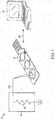
- FIG. 1illustrates a system 10 for magnetic coupling.
- the system 10includes an external computing device 12, a printed circuit board 14, and a circuit 16.
- the external computing device 12may include, for example, a desktop computer, a laptop computer, a tablet computer, a communication device, such as a smart telephone or smart wearable, and the like.
- the external computing device 12can be in communication with (e.g., transmits data to or receives data from) the printed circuit board 14 through a wired or wireless connection 17a.
- the external computing device 12communicates with the printed circuit board 14 over a wired connection (e.g., via a universal serial bus (USB®) cable, Firewire®, Thunderbolt® port, and the like).
- USB®universal serial bus
- the external computing device 12can provide power (e.g., 5 volts direct current (DC)) to the printed circuit board 14 via the wired connection, which powers components (e.g., a microcontroller, an integrated circuit, and the like) of the printed circuit board 14.
- a wireless connectionsuch as Bluetooth® or Wi-Fi®, is used for communications between the printed circuit board 14 and the external computing device 12.
- a portable power supplye.g., a battery
- a batterymay be coupled to the printed circuit board 14 to provide power.
- the printed circuit board 14(e.g., a circuit board) mechanically supports and electrically connects electronic components (e.g., microcontroller, memory, integrated circuits, resistors, capacitors, inductors, and the like) using conductive tracks, pads, and other features etched from conductive sheets (e.g., copper sheets) laminated onto a non-conductive substrate (e.g., an electrical insulator).
- the electronic components on the printed circuit board 14can be bonded to the conductive tracks with conductive materials, such as solder.
- the electronic components on the printed circuit board 14can be coupled (e.g., via electrical connectors and cables) to the printed circuit board 14.
- the printed circuit board 14can also include connectors to couple the printed circuit board 14 to other devices.
- the connectorscan provide a semi-permanent connection to the printed circuit board 14.
- the connectorscan be held in place by friction (e.g., tight tolerances between mating features), latching mechanisms, threaded features (e.g., F connector, BNC (Bayonet Neill-Concelman) connector, or RS-232 connector), and/or resilient members (e.g., springs).
- the printed circuit board 14can be a programmable device.
- the printed circuit board 14is a computer peripheral device that simulates, for example, a keyboard or mouse, based on user inputs.
- the printed circuit board 14can communicate with the circuit 16 via a connection 17b.
- the connection 17bis a wired connection.
- the circuit 16can be a conductive circuit loop including a conductive element 18 (illustrated as a resistor) coupled to ground.
- FIG. 1illustrates the conductive element 18, any material that can conduct electricity, even if only slightly, may be implemented.
- the conductive element 18can include an apple, ketchup, pencil graphite, finger paint, lemons, plants, coins, other humans, silverware, water (and wet objects), most foods, cats, dogs, aluminum roil, rain, and the like.
- the printed circuit board 14may be configured to detect the selective presence and absence of the conductive element 18 which completes or opens a circuit loop.
- the conductive element 18e.g., an apple
- the conductive element 18may be selectively inserted into the circuit 16 and selectively remove from the circuit 16 by selectively grounding the apple and disconnecting the apple from ground, respectively.
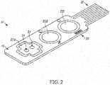
- FIG. 2illustrates the printed circuit board 14 in more detail.
- the printed circuit board 14includes a connector side 19 and a back side 20 opposite the connector side 19.
- the connector side 19can include one or more contact pads 22A, 22B, and 22C.
- the contact pads 22A, 22B, and 22Ccan be etched in the printed circuit board 14 and can be coupled to electronic components (e.g., a microcontroller, an integrated circuit, and the like) mounted on the printed circuit board 14 via, for example, conductive traces on the printed circuit board 14. It should be understood that the contact pads can be positioned on other surfaces of the printed circuit board 14 (e.g., the back side 20).
- the printed circuit board 14includes three contact pads (e.g., contact pads 22A, 22B, and 22C) on the connector side 19.
- the contact pad 22Ais in the shape of a cross while contact pads 22B and 22C are in the shape of a circle. It is to be understood that although three contact pads are described herein, more or less contact pads can be implemented.
- the contact pads 22A, 22B, and 22Care described herein as a cross and a circle, the contact pads can include other shapes (e.g., a circle, a triangle, a rectangle, a square, an oval, a heart, and the like) and may vary in combination of shapes.
- the connector side 19may include two contact pads where one contact pad is a triangle and the second contact pad is a square or both contact pads can be squares.
- the contact pads 22A, 22B, and 22Ccan include one or more openings or apertures that can penetrate the printed circuit board 14 to some degree (e.g., full penetration or partial penetration).
- the contact pad 22Aincludes two circular apertures 24 that fully penetrate the printed circuit board 14.
- FIG. 2illustrates only one contact pad (e.g., contact pad 22A) having apertures, some embodiments include additional contact pads having apertures.
- a contact padcan include more or less apertures.
- the apertures 24are illustrated as being circular, it is to be understood that the apertures can take the form of other shapes (e.g., a circle, triangle, rectangle, heart, cross, and the like).
- the apertures 24can fully or partially penetrate the printed circuit board 14. In some embodiments, one aperture can penetrate the printed circuit board 14 more or less than another aperture. In other words, the apertures may penetrate the printed circuit board 14 at various combinations of penetration degrees. In accordance with some embodiments, the surface of the apertures 24 can be coated with a conductive material causing the apertures 24 to be electrically coupled to the contact pad 24 and/or a magnet.
- the printed circuit board 14can also include a communication terminal 26.
- the communication terminal 26may be integrated into the printed circuit board 14, and take the form of a universal serial bus (USB®) plug.
- the communication terminal 26is a communication port (e.g., a USB® port) that receives a communication plug (e.g., a USB® plug, and the like).
- the communication terminal 26can enable the printed circuit board 14 to communicate, as described above, with the external computing device 12.
- a computing terminale.g., a USB® port
- a computing terminale.g., a USB® port
- the external computing device 12can receive the communication terminal 26 of the printed circuit board 14.
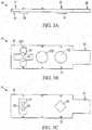
- FIGS. 3A and 3Billustrate a side view and a top view, respectively, of the printed circuit board 14.
- a magnet 28e.g., a permanent magnet or an object that produces a magnetic field
- the magnet 28is aligned with the apertures 24.
- the magnet 28is transparently represented by a dashed line and is aligned with the apertures 24.
- the surface area of the magnet 28 abutting the back side 20is greater than the area of the opening of the each apertures 24 individually and in combination.
- each contact padcan have a corresponding magnet positioned opposite each contact pad.
- the magnet 28can provide a magnetic attraction force for multiple contact pads. In other embodiments, multiple magnets can be used for a single contact pad.
- the magnet 28may be any size or shape.
- the magnet 28can be larger than the apertures 24 in the printed circuit board 14 (as seen in FIG. 3C ), can match the area of the contact pads 22A, 22B, and 22C, or can be smaller than the area of the contact pads 22A, 22B, 22C.
- the magnet 28has partial or full apertures that align with the apertures 24.
- the magnetic field provided by the magnet 28provides magnetic attraction forces.
- the magnetic attraction forcesattract (e.g., pull) on other ferromagnetic materials, such as iron, steel, nickel, and cobalt. Ferromagnetic materials have a strong attractive force to a magnetic field while other materials have a weaker attractive force to a magnetic field.
- the magnetic attraction forcecan attract a metallic end (e.g., a ferromagnetic end) of an electric cable (e.g., an alligator clip).
- the magnetic attraction forcecan hold the metallic end in place to provide and ensure an electrical connection between the corresponding contact pad and the connector (e.g., an alligator clip).
- the magnet 28alone can provide a sufficient attraction forces to maintain a connection of a metallic cable and a contact pad on the printed circuit board 14, or the magnet 28 in conjunction with another semi-permanent connector (e.g., close-biased "alligator clips") may be used to electrically couple a cable to a contact pad.
- another semi-permanent connectore.g., close-biased "alligator clips”
- the magnet 28can be bonded (e.g., via an adhesive) to the back side 20 of the printed circuit board 14 or the magnet 28 can be integrated into the printed circuit board 14 (e.g., as a layer in the printed circuit board 14). In some embodiments, the magnet 28 can be bonded (e.g., via an adhesive) to a housing 32 (seen in FIG. 4 ) that encloses the printed circuit board 14 and the electrical components of the printed circuit board 14.
- the printed circuit board 14also includes an integrated circuit 30 (IC) (e.g., a microprocessor, application specific integrated circuit, and the like).
- ICintegrated circuit
- the integrated circuit 30can be positioned on the same surface (e.g., the back side 20) of the printed circuit board 14 as the magnet 28.
- the integrated circuit 30can be electrically coupled to the contact pad (e.g., contact pad 22A) of the printed circuit board 14 associated with the apertures 24.
- an input pin or an output pin of the integrated circuit 30may be electrically connected through conductive traces on the printed circuit board 14 to the contact pad 22A.
- the contact pad 22Amay be connected to another circuit on the printed circuit board 14 that is monitored by a sensor that has an output coupled to an input pin of the integrated circuit 30. Accordingly, an integrated circuit 30 can receive a user input via the contact pad 22A and/or the integrated circuit 30 can provide an output to the contact pad 22A.
- FIG. 4is an exploded view of the housing 32, the printed circuit board 14, and the magnet 28.
- the housing 32provides an aesthetic design and allows a user to handle the printed circuit board 14 without damaging the printed circuit board 14, the electronic components on the printed circuit board 14, or the electrical connection on the printed circuit board 14.
- the housing 32allows the user to easily plug (e.g., connect) the communication terminal 26 of the printed circuit board 14 into a USB® port of the external computing device 12 and unplug (e.g., disconnect) the communication terminal 26 of the printed circuit board 14 from the USB® port of the external computing device 12.
- the housing 32can also have an opening 33 for inserting a lanyard, such as a key chain.
- the housing 32includes a first enclosure 32A and a second enclosure 32B.
- the first enclosure 32A and the second enclosure 32Bcan be attachable.
- the printed circuit board 14can be positioned between the first enclosure 32A and the second enclosure 32B.
- the first enclosure 32A and the second enclosure 32Binclude a plurality of alignment features 35 (e.g., posts).
- the plurality of alignment features 35fix, secure, and align the printed circuit board 14 in a specific position within the housing 32 when the first enclosure 32A and the second enclosure 32B are attached.
- the first enclosure 32Aincludes a first plurality of alignment features (not shown) and the second enclosure 32B includes a second corresponding plurality of alignment features 35 (such as alignment feature 35a).
- the plurality of alignment features 35can be formed in the first enclosure 32A and the second enclosure 32B or can be bonded (e.g., via an adhesive) to the first enclosure 32A and the second enclosure 32B.
- the plurality of alignment features 35may be various configurations.
- the printed circuit board 14includes a plurality of alignment features 35 (such as alignment feature 35b) integrated into or coupled to the printed circuit board 14 that mate with a plurality of corresponding alignment features 35 in the first enclosure 32A and the second enclosure 32B.
- the plurality of alignment features 35bare shown on the connector side 19 of the printed circuit board 14, but in other examples the plurality of alignment features 35 can be on the back side 20 of the printed circuit board 14.
- the magnet 28can be held in a specific position by a magnet restraint 36.
- the magnet restraint 36can be formed within the housing 32 and can align the magnet 28 with the apertures 24 in the printed circuit board 14.
- the magnet restraint 36can be a raised ridge around the perimeter of the magnet 28 forming a magnet receptacle 37. The raised edge of the magnet restraint 36 can fully or partially enclose the magnet 28.
- the magnet restraint 36is designed to allow for easy removal of the magnet to loosely fit within the magnet restraint 36 to allow for the magnet 28 when the printed circuit board 14 is removed from the housing 32.
- the magnet restraint 26can use other features to fix the position of the magnet 28 relative to the contact pads 22A, 22B, and 22C of the printed circuit board 14.
- FIG. 5illustrates a perspective view of the printed circuit board 14 (transparent) when the printed circuit board 14 is positioned within the housing 32 (e.g., between the first enclosure 32A and the second enclosure 32B).
- the magnet 28can be positioned within the magnet restraint 36 so that the magnet 28 is positioned opposite the entry ways of the apertures 24.
- the first enclosure 32Acan include an opening 34 that exposes the contact pads 22A, 22B, and 22C on the connector side 19 of the printed circuit board 14 to the external environment.
- the opening 34provides ease of access to the contact pads 22A, 22B, and 22B and the apertures 24 for magnetically coupling a connector to the printed circuit board 14.
- FIG. 6illustrates a method 40 of magnetic coupling using the system 10 shown in FIG. 1 .
- the method 40includes receiving, by the communication terminal 26 of the printed circuit board 14, computer terminals of the external computing device 12 (at block 42).
- the communication terminal 26can be a communication plug or a communication port that can receive computer terminals through connection to a corresponding communication port or plug of the external computing device 12.
- the method 40also includes receiving, by a contact pad (e.g., contact pads 22A, 22B, and 22C) on the connector side 19 of the printed circuit board 14, a connector coupled to the circuit 16 (at block 44).
- the connectorcan be received by touching the connector to one of the plurality of contact pads 22A, 22B, and 22C.
- a connector 52e.g., an alligator clip
- the connector 52is positioned on an outer surface of the contact pad 22A outside of the apertures 24 rather than being recessed within either of the apertures 24.
- the connectorcan be received by inserting the connector into an aperture in one of the plurality of contact pads 22A, 22B, and 22C.
- the aperturemay also provide a friction fit between the aperture and the connector that enhances the coupling to the contact pad on the printed circuit board.
- a connector 52e.g., an alligator clip
- the connector 52is received by inserting both the jaws of the connector 52 into one of the apertures 24 in the contact pad 22A.
- the connectorcan be received by inserting two resilient ends of the connector (e.g., two spring-biased jaws of an alligator clip) into two apertures of the contact pad as well as clamping the connector to a bridge portion of the printed circuit board separating the two apertures.
- the connector 52e.g., an alligator clip
- the connector 52is received by inserting each jaw of the alligator clip into a corresponding one of the apertures 24 of the contact pad 22A.
- the jawsassist in retaining the connector 52 by clamping a bridge portion 54 of the printed circuit board 14 between the two apertures 24 in the contact pad 22A.
- the magnetic attraction forcesare provided, by the magnet 28 positioned on the back side 20 of the printed circuit board 14 opposite the connector side 19, to attract the connector 52 to the contact pad (e.g., one of the plurality of contact pads 22A, 22B, and 22C) (at block 46).
- the contact pade.g., one of the plurality of contact pads 22A, 22B, and 22C
- the connector 52in response to the magnetic attraction forces provided by the magnet 28, when the connector 52 is touching the contact pad 22A on the connector side 19 of the printed circuit board 14, the connector 52 is magnetically coupled to the contact pad 22A.
- the magnetic coupling configuration illustrated in FIG. 7Arelative to those of FIGS. 7B and 7C , provides an electrical connection with the greatest distance between the metallic end of the connector 52 and the magnet 28 because the connector 52 is separated from the magnet 28 by the printed circuit board 14.
- Such a magnetic coupling configurationenables the user to quickly make an electrical connection between the connector 52 and at least one of the plurality of contact pads 22A, 22B, and 22C without precisely aiming or aligning the metallic end of the connector 52 to one or more of the apertures 24.
- the connector 52in response to the magnetic attraction forces provided by the magnet 28, when the connector 52 is inserted into the aperture 24 in the contact pad 22A on the connector side 19 of the printed circuit board 14, the connector 52 is magnetically coupled to the contact pad 22A.
- the magnetic coupling configuration illustrated in FIG. 7Bprovides a full electrical connection and a stronger magnetic coupling configuration than the magnetic coupling configuration shown in FIG. 7A .
- the magnetic field provided by the magnet 28is stronger in the aperture 24 because the space between the magnet 28 and the connector 52 is reduced or eliminated relative to the magnetic coupling configuration illustrated in FIG. 7A .
- the magnetic coupling configuration illustrated in FIG. 7Bprovides a quick coupling technique for magnetically coupling the connector 52 to the contact pad 22A without needing to use the clamping feature of the connector 52.
- the connector 52in response to the magnetic attraction forces provided by the magnet 28, when the connector 52 is inserted into the apertures 24 and is attached to the bridge portion 54 of the printed circuit board 14 separating the two apertures 24, the connector 52 is magnetically coupled to the contact pad 22A as well as mechanically coupled to the contact pad 22A (e.g., clamping the alligator clip to the bridge portion of the printed circuit board 14).
- the magnetic coupling configurations illustrated in FIGS. 7A-7Cprovide various strengths of magnetic and mechanical coupling to the connector 52 (e.g., the alligator clip) using the same contact pad (e.g., contact pad 22A).
- the magnetic coupling configurationmay maintain an electrical connection in situations where the connector 52 (e.g., the alligator clip) accidentally becomes mechanically disengaged from the apertures 24.
- the magnetic coupling configurationwill switch to the magnetic coupling configuration of FIG. 7A or the magnetic coupling configuration of FIG. 7B as a result of the magnetic attraction forces acting on the metallic end of the connector 52, presuming the initial mechanical disengagement does not move the connector 52 outside of the range of magnetic attraction forces of the magnet 28.
- the electric connectionis maintained.
- the apertures 24enable a quick connection of, for example, alligator clip cables (e.g., the connector 52) because each half of the alligator clip is received by a respective aperture and the spring-loaded alligator clip clamps onto the bridge portion of the printed circuit board 14 separating the two apertures 24.
- alligator clip cablese.g., the connector 52
- the apertures 24may receive pin connectors sized to fit within the apertures 24 and provide a level of friction-based retainment in addition to being subject to attraction forces of the magnet 28.
- a logic circuit (e.g., integrated circuit 30) of the printed circuit board 14receives a first signal from the circuit 16 via the contact pad 22A.
- the first signalcan be received via the electrical connection between the connector 52, the contact pad 22A, and the printed circuit board 14, as described above.
- the first signalresults from completing a conductive circuit loop in the circuit 16. For example, if a person completes the conductive circuit loop within the circuit 16 (e.g., by touching an apple), the printed circuit board 14 detects the completion of the conductive circuit loop (e.g., detects the first signal).
- the printed circuit board 14may include sensing circuitry (e.g., a voltage or current sensor) coupled to the integrated circuit 30 to detect the first signal.
- a second signalis output by the logic circuit (e.g., the integrated circuit 30) to the external computing device 12 via the communication terminal 26 of the printed circuit board 14 (at block 50).
- the logic circuite.g., the integrated circuit 30
- the printed circuit board 14detects the completion of the conductive circuit loop (e.g., the integrated circuit 30 detects the first signal)
- the printed circuit board 14e.g., the integrated circuit 30
- the second signalcan, for example, be a signal associated with a keyboard action or a mouse action (e.g., key press, mouse click, or mouse movement).
- the external computing device 12can, for example, react as if the second signal were sent from a standard keyboard or mouse. Therefore, a user, such as the person in the above example, can simulate a key stroke on a keyboard by touching the conductive element 18 of the circuit 16 and the external computing device 12 will receive the simulated key stroke and react as if the user had pressed the actual key on the key board that is being simulated. For instance, in a word processing program, and where the key stroke simulated is the letter "w,” upon the user touching the conductive element 18, the word processing program would react as if the user pressed the "w" on the keyboard and display a new "w" on a display of the external computing device 12.
- steps of the method 40are shown and described as occurring serially, one or more step may occur in a different order, simultaneously, or both.
Landscapes
- Engineering & Computer Science (AREA)
- Microelectronics & Electronic Packaging (AREA)
- Theoretical Computer Science (AREA)
- Human Computer Interaction (AREA)
- Physics & Mathematics (AREA)
- General Engineering & Computer Science (AREA)
- General Physics & Mathematics (AREA)
- Coupling Device And Connection With Printed Circuit (AREA)
- Combinations Of Printed Boards (AREA)
Description
- The present invention relates to methods and systems for coupling a conductive connector to a printed circuit board.
- Printed circuit boards may be coupled, either permanently or semi-permanently, to external devices or circuits. Semi-permanent coupling can be achieved through a selectively releasable mechanical coupling (e.g., attaching an alligator clip). However, such mechanical coupling may involve precise aiming and alignment. Furthermore, in some situations the mechanical coupling can accidently become mechanically disengaged. Document
US-A1-2015/111399 discloses an electrical connector assembly comprising an electrode interface board with a socket portion of an electrical connector attached to the top surface of a first printed circuit board and a first plurality of magnets attached to the bottom surface. The connector assembly further comprises a head stage with a second printed circuit board. A plug portion of the electrical connector and a second plurality of magnets are attached to the bottom surface of the second printed circuit board. - Accordingly, there is a need for improved systems and methods of coupling. In particular, a coupling configuration that enables the user to quickly make an electrical connection without precise aiming or aligning is desirable. Furthermore, a coupling configuration that maintains an electrical connection in situations where the mechanical coupling accidentally becomes mechanically disengaged is also desirable. The subject matter is defined by the subject matter of the independent claims.
- Accordingly, the invention relates to methods and systems for magnetic coupling, such as magnetically coupling a conductive connector with a printed circuit board (e.g., a circuit board) to provide an electrical connection. For example, one embodiment of the invention provides a system for magnetically coupling a plurality of electronic components. The system includes an external computing device and a connector having a conductive end. The system also includes a printed circuit board. The printed circuit board includes a connector side opposite a back side. The connector side having a contact pad with an
aperture. The printed circuit board also includes a magnet positioned on the back side of the printed circuit board. The magnet providing a magnetic field configured to provide magnetic attraction forces to a connector contacting the contact pad. The printed circuit board also includes a communication terminal. The system also includes a circuit in communication with the printed circuit board through the connector and contact pad. - Another embodiment of the invention provides a peripheral device. The peripheral device includes a connector side opposite a back side. The connector side having a contact pad with an aperture. The peripheral device also includes a magnet positioned on the back side of the peripheral device. The magnet providing a magnetic field configured to provide magnetic attraction forces to a connector contacting the contact pad. The peripheral device also includes a communication terminal.
- Yet another embodiment the invention provides a method of magnetic coupling. The method includes receiving, by a communication terminal of a printed circuit board, computer terminals of an external computing device. The method also includes receiving, by a contact pad on a connector side of the printed circuit board, a connector coupled to a circuit. The method also includes providing magnetic attraction forces, by a magnet positioned on a back side of the printed circuit board opposite the connector side, to attract the connector to the contact pad. The method also includes receiving, by a logic circuit of the printed circuit board, a first signal from the circuit via the contact pad. The method also includes outputting a second signal to the external computing device via the communication terminal in response to the first signal.
- Other aspects of the invention will become apparent by consideration of the detailed description and accompanying drawings.
FIG. 1 illustrates a schematic diagram of a system for magnetic coupling that includes an external computing device, a printed circuit board, and a circuit.FIG. 2 illustrates the printed circuit board ofFIG. 1 .FIG. 3A illustrates a side view of the printed circuit board ofFIG. 2 .FIG. 3B illustrates a top view of the printed circuit board ofFIG. 2 .FIG. 3C illustrates a transparent top view of the printed circuit board ofFIG. 2 .FIG. 4 illustrates an exploded view of the printed circuit board ofFIG. 2 .FIG. 5 illustrates a perspective view of the printed circuit board (transparent) ofFIG. 2 in a housing with a magnet positioned below the transparent printed circuit board.FIG. 6 illustrates a method of magnetic coupling using the system ofFIG. 1 .FIG. 7A illustrates a perspective view of coupling a connector to the printed circuit board ofFIG. 2 by touching the connector to a contact pad on the printed circuit board.FIG. 7B illustrates a perspective view of coupling a connector to the printed circuit board ofFIG. 2 by inserting the connector into an aperture of a contact pad on the printed circuit board.FIG. 7C illustrates a perspective view of coupling a connector to the printed circuit board ofFIG. 2 by inserting two resilient ends of the connector into apertures of the contact pad as well as clamping the connector to a bridge portion of the printed circuit board separating the apertures.- Before illustrating examples useful for the understanding of the invention are explained in detail, it is to be understood that the invention is not limited in its application to the details of construction and the arrangement of components set forth in the following description or illustrated in the following drawings.
- It should also be noted that a plurality of hardware and software based devices, as well as a plurality of different structural components may be used to implement the invention. In addition, it should be understood that the invention may include hardware, software, and electronic components or modules that, for purposes of discussion, may be
illustrated and described as if the majority of the components were implemented solely in hardware. However, one of ordinary skill in the art, and based on a reading of this detailed description, would recognize that, in at least one example, the electronic based aspects of the invention may be implemented in software (e.g., stored on non-transitory computer-readable medium) executable by one or more processors. As such, it should be noted that a plurality of hardware and software based devices, as well as a plurality of different structural components may be utilized to implement the invention. FIG. 1 illustrates asystem 10 for magnetic coupling. Thesystem 10 includes anexternal computing device 12, a printedcircuit board 14, and acircuit 16. Theexternal computing device 12 may include, for example, a desktop computer, a laptop computer, a tablet computer, a communication device, such as a smart telephone or smart wearable, and the like. Theexternal computing device 12 can be in communication with (e.g., transmits data to or receives data from) the printedcircuit board 14 through a wired or wireless connection 17a. In some embodiments, theexternal computing device 12 communicates with the printedcircuit board 14 over a wired connection (e.g., via a universal serial bus (USB®) cable, Firewire®, Thunderbolt® port, and the like). Theexternal computing device 12 can provide power (e.g., 5 volts direct current (DC)) to the printedcircuit board 14 via the wired connection, which powers components (e.g., a microcontroller, an integrated circuit, and the like) of the printedcircuit board 14. In other embodiments, in place of or in addition to the wired connection, a wireless connection, such as Bluetooth® or Wi-Fi®, is used for communications between the printedcircuit board 14 and theexternal computing device 12. In wireless implementations or implementations where a wired connection does not provide power, a portable power supply (e.g., a battery) may be coupled to the printedcircuit board 14 to provide power.- The printed circuit board 14 (e.g., a circuit board) mechanically supports and electrically connects electronic components (e.g., microcontroller, memory, integrated circuits, resistors, capacitors, inductors, and the like) using conductive tracks, pads, and other features etched from conductive sheets (e.g., copper sheets) laminated onto a non-conductive substrate (e.g., an electrical insulator). The electronic components on the printed
circuit board 14 can be bonded to the conductive tracks with conductive materials, such as
solder. In other embodiments, the electronic components on the printedcircuit board 14 can be coupled (e.g., via electrical connectors and cables) to the printedcircuit board 14. - The printed
circuit board 14 can also include connectors to couple the printedcircuit board 14 to other devices. The connectors can provide a semi-permanent connection to the printedcircuit board 14. The connectors can be held in place by friction (e.g., tight tolerances between mating features), latching mechanisms, threaded features (e.g., F connector, BNC (Bayonet Neill-Concelman) connector, or RS-232 connector), and/or resilient members (e.g., springs). - The printed
circuit board 14 can be a programmable device. For example, the printedcircuit board 14 is a computer peripheral device that simulates, for example, a keyboard or mouse, based on user inputs. - As illustrated in
FIG. 1 , the printedcircuit board 14 can communicate with thecircuit 16 via a connection 17b. The connection 17b is a wired connection. Thecircuit 16 can be a conductive circuit loop including a conductive element 18 (illustrated as a resistor) coupled to ground. AlthoughFIG. 1 illustrates theconductive element 18, any material that can conduct electricity, even if only slightly, may be implemented. For example, theconductive element 18 can include an apple, ketchup, pencil graphite, finger paint, lemons, plants, coins, other humans, silverware, water (and wet objects), most foods, cats, dogs, aluminum roil, rain, and the like. The printedcircuit board 14 may be configured to detect the selective presence and absence of theconductive element 18 which completes or opens a circuit loop. For example, the conductive element 18 (e.g., an apple) may be selectively inserted into thecircuit 16 and selectively remove from thecircuit 16 by selectively grounding the apple and disconnecting the apple from ground, respectively. FIG. 2 illustrates the printedcircuit board 14 in more detail. The printedcircuit board 14 includes aconnector side 19 and aback side 20 opposite theconnector side 19. Theconnector side 19 can include one ormore contact pads contact pads circuit board 14 and can be coupled to electronic components (e.g., a microcontroller, an integrated circuit, and the like) mounted on the printedcircuit board 14 via, for example, conductive traces on the printedcircuit board 14. It should be understood that the contact pads can be positioned on other surfaces of the printed circuit board 14 (e.g., the back side 20).- For example, as shown in
FIG. 2 , the printedcircuit board 14 includes three contact pads (e.g.,contact pads connector side 19. Thecontact pad 22A is in the shape of a cross whilecontact pads contact pads connector side 19 may include two contact pads where one contact pad is a triangle and the second contact pad is a square or both contact pads can be squares. - In some embodiments, the
contact pads circuit board 14 to some degree (e.g., full penetration or partial penetration). For example, as illustrated inFIG. 2 , thecontact pad 22A includes twocircular apertures 24 that fully penetrate the printedcircuit board 14. AlthoughFIG. 2 illustrates only one contact pad (e.g.,contact pad 22A) having apertures, some embodiments include additional contact pads having apertures. Furthermore, in some embodiments, a contact pad can include more or less apertures. Additionally, although theapertures 24 are illustrated as being circular, it is to be understood that the apertures can take the form of other shapes (e.g., a circle, triangle, rectangle, heart, cross, and the like). Theapertures 24 can fully or partially penetrate the printedcircuit board 14. In some embodiments, one aperture can penetrate the printedcircuit board 14 more or less than another aperture. In other words, the apertures may penetrate the printedcircuit board 14 at various combinations of penetration degrees. In accordance with some embodiments, the surface of theapertures 24 can be coated with a conductive material causing theapertures 24 to be electrically coupled to thecontact pad 24 and/or a magnet. - The printed
circuit board 14 can also include acommunication terminal 26. Thecommunication terminal 26 may be integrated into the printedcircuit board 14, and take the form of a universal serial bus (USB®) plug. In some embodiments, thecommunication terminal 26 is a communication port (e.g., a USB® port) that receives a communication plug (e.g., a USB® plug, and the like). Thecommunication terminal 26 can enable the printedcircuit board 14 to communicate, as described above, with theexternal computing device 12. For example, a computing terminal (e.g., a USB® port) of theexternal computing device 12 can receive thecommunication terminal 26 of the printedcircuit board 14. FIGS. 3A and 3B illustrate a side view and a top view, respectively, of the printedcircuit board 14. As illustrated inFIG. 3A , a magnet 28 (e.g., a permanent magnet or an object that produces a magnetic field) can be positioned on theback side 20 of the printedcircuit board 14. In accordance with some embodiments, themagnet 28 is aligned with theapertures 24. For example, as illustrated inFIG. 3C , themagnet 28 is transparently represented by a dashed line and is aligned with theapertures 24. As also illustrated inFIG. 3C , the surface area of themagnet 28 abutting theback side 20 is greater than the area of the opening of the eachapertures 24 individually and in combination.- Although a single magnet is shown, multiple magnets can be used. For example, each contact pad can have a corresponding magnet positioned opposite each contact pad. In some embodiments, the
magnet 28 can provide a magnetic attraction force for multiple contact pads. In other embodiments, multiple magnets can be used for a single contact pad. Furthermore, it should be understood that themagnet 28 may be any size or shape. For example, themagnet 28 can be larger than theapertures 24 in the printed circuit board 14 (as seen inFIG. 3C ), can match the area of thecontact pads contact pads magnet 28 has partial or full apertures that align with theapertures 24. - The magnetic field provided by the
magnet 28 provides magnetic attraction forces. The magnetic attraction forces attract (e.g., pull) on other ferromagnetic materials, such as iron, steel, nickel, and cobalt. Ferromagnetic materials have a strong attractive force to a magnetic field while other materials have a weaker attractive force to a magnetic field. For example, the magnetic attraction force can attract a metallic end (e.g., a ferromagnetic end) of an electric cable (e.g., an alligator clip). The magnetic attraction force can hold the metallic end in place to provide and ensure an electrical connection between the corresponding contact pad and the connector (e.g., an alligator clip). In some embodiments, themagnet 28 alone can provide a sufficient attraction forces to maintain a connection of a metallic cable and a contact pad on the printedcircuit board 14, or themagnet 28 in conjunction with another semi-permanent connector (e.g., close-biased "alligator clips") may be used to electrically couple a cable to a contact pad. - The
magnet 28 can be bonded (e.g., via an adhesive) to theback side 20 of the printedcircuit board 14 or themagnet 28 can be integrated into the printed circuit board 14 (e.g., as a layer in the printed circuit board 14). In some embodiments, themagnet 28 can be bonded (e.g., via an adhesive) to a housing 32 (seen inFIG. 4 ) that encloses the printedcircuit board 14 and the electrical components of the printedcircuit board 14. - As seen in
FIGS. 3A and 3C , in some embodiments, the printedcircuit board 14 also includes an integrated circuit 30 (IC) (e.g., a microprocessor, application specific integrated circuit, and the like). Theintegrated circuit 30 can be positioned on the same surface (e.g., the back side 20) of the printedcircuit board 14 as themagnet 28. Theintegrated circuit 30 can be electrically coupled to the contact pad (e.g.,contact pad 22A) of the printedcircuit board 14 associated with theapertures 24. For example, an input pin or an output pin of theintegrated circuit 30 may be electrically connected through conductive traces on the printedcircuit board 14 to thecontact pad 22A. In some embodiments, thecontact pad 22A may be connected to another circuit on the printedcircuit board 14 that is monitored by a sensor that has an output coupled to an input pin of theintegrated circuit 30. Accordingly, anintegrated circuit 30 can receive a user input via thecontact pad 22A and/or theintegrated circuit 30 can provide an output to thecontact pad 22A. FIG. 4 is an exploded view of thehousing 32, the printedcircuit board 14, and themagnet 28. Thehousing 32 provides an aesthetic design and allows a user to handle the printedcircuit board 14 without damaging the printedcircuit board 14, the electronic components on the printedcircuit board 14, or the electrical connection on the printedcircuit board 14. For example, thehousing 32 allows the user to easily plug (e.g., connect) thecommunication terminal 26 of the printedcircuit board 14 into a USB® port of theexternal computing device 12 and unplug (e.g., disconnect) thecommunication terminal 26 of the printedcircuit board 14 from the USB® port of theexternal computing device 12. Thehousing 32 can also have anopening 33 for inserting a lanyard, such as a key chain.- As seen in
FIG. 4 , according to some embodiments, thehousing 32 includes afirst enclosure 32A and asecond enclosure 32B. Thefirst enclosure 32A and thesecond enclosure 32B can be attachable. When thefirst enclosure 32A and thesecond enclosure 32B are attached, the printedcircuit board 14 can be positioned between thefirst enclosure 32A and thesecond enclosure 32B. - In some embodiments, the
first enclosure 32A and thesecond enclosure 32B (e.g., the housing 32) include a plurality of alignment features 35 (e.g., posts). The plurality of alignment features 35 fix, secure, and align the printedcircuit board 14 in a specific position within thehousing 32 when thefirst enclosure 32A and thesecond enclosure 32B are attached. Thefirst enclosure 32A includes a first plurality of alignment features (not shown) and thesecond enclosure 32B includes a second corresponding plurality of alignment features 35 (such as alignment feature 35a). The plurality of alignment features 35 can be formed in thefirst enclosure 32A and thesecond enclosure 32B or can be bonded (e.g., via an adhesive) to thefirst enclosure 32A and thesecond enclosure 32B. It is to be understood that the plurality of alignment features 35 may be various configurations. In some embodiments, the printedcircuit board 14 includes a plurality of alignment features 35 (such as alignment feature 35b) integrated into or coupled to the printedcircuit board 14 that mate with a plurality of corresponding alignment features 35 in thefirst enclosure 32A and thesecond enclosure 32B. For example, as seen inFIG. 4 , the plurality of alignment features 35b are shown on theconnector side 19 of the printedcircuit board 14, but in other examples the plurality of alignment features 35 can be on theback side 20 of the printedcircuit board 14. - As illustrated in
FIG. 4 , themagnet 28 can be held in a specific position by amagnet restraint 36. In some embodiments, themagnet restraint 36 can be formed within thehousing 32 and can align themagnet 28 with theapertures 24 in the printedcircuit board 14. Themagnet restraint 36 can be a raised ridge around the perimeter of themagnet 28 forming amagnet receptacle 37. The raised edge of themagnet restraint 36 can fully or partially enclose themagnet 28. In some embodiments, themagnet restraint 36 is designed to allow for easy removal of the magnet to loosely fit within themagnet restraint 36 to allow for themagnet 28 when the printedcircuit board 14 is removed from thehousing 32. In some embodiments, themagnet restraint 26 can use other features to fix the position of themagnet 28 relative to thecontact pads circuit board 14. FIG. 5 illustrates a perspective view of the printed circuit board 14 (transparent) when the printedcircuit board 14 is positioned within the housing 32 (e.g., between thefirst enclosure 32A and thesecond enclosure 32B). As seen inFIG. 5 , themagnet 28 can be positioned within themagnet restraint 36 so that themagnet 28 is positioned opposite the entry ways of theapertures 24. Thefirst enclosure 32A can include anopening 34 that exposes thecontact pads connector side 19 of the printedcircuit board 14 to the external environment. Theopening 34 provides ease of access to thecontact pads apertures 24 for magnetically coupling a connector to the printedcircuit board 14.FIG. 6 illustrates amethod 40 of magnetic coupling using thesystem 10 shown inFIG. 1 . Themethod 40 includes receiving, by thecommunication terminal 26 of the printedcircuit board 14, computer terminals of the external computing device 12 (at block 42). As described above, thecommunication terminal 26 can be a communication plug or a communication port that can receive computer terminals through connection to a corresponding communication port or plug of theexternal computing device 12.- The
method 40 also includes receiving, by a contact pad (e.g.,contact pads connector side 19 of the printedcircuit board 14, a connector coupled to the circuit 16 (at block 44). In some embodiments, the connector can be received by touching the connector to one of the plurality ofcontact pads FIG. 7A , a connector 52 (e.g., an alligator clip) is received by touching theconnector 52 to thecontact pad 22A. As illustrated, theconnector 52 is positioned on an outer surface of thecontact pad 22A outside of theapertures 24 rather than being recessed within either of theapertures 24. In some embodiments, the connector can be received by inserting the connector into an aperture in one of the plurality ofcontact pads FIG. 7B , a connector 52 (e.g., an alligator clip) is received by inserting both the jaws of theconnector 52 into one of theapertures 24 in thecontact pad 22A. In some embodiments, the connector can be received by inserting two resilient ends of the connector (e.g., two spring-biased jaws of an alligator clip) into two apertures of the contact pad as well as clamping the connector to a bridge portion of the printed circuit board separating the two apertures. For example, as illustrated inFIG. 7C , the connector 52 (e.g., an alligator clip) is received by inserting each jaw of the alligator clip into a corresponding one of theapertures 24 of thecontact pad 22A. The jaws assist in retaining theconnector 52 by clamping abridge portion 54 of the printedcircuit board 14 between the twoapertures 24 in thecontact pad 22A. - Returning to
FIG. 6 , the magnetic attraction forces, as described above, are provided, by themagnet 28 positioned on theback side 20 of the printedcircuit board 14 opposite theconnector side 19, to attract theconnector 52 to the contact pad (e.g., one of the plurality ofcontact pads - For example, as seen in
FIG. 7A , in response to the magnetic attraction forces provided by themagnet 28, when theconnector 52 is touching thecontact pad 22A on theconnector side 19 of the printedcircuit board 14, theconnector 52 is magnetically coupled to thecontact pad 22A. The magnetic coupling configuration illustrated inFIG. 7A , relative to those ofFIGS. 7B and7C , provides an electrical connection with the greatest distance between the metallic end of theconnector 52 and themagnet 28 because theconnector 52 is separated from themagnet 28 by the printedcircuit board 14. Such a magnetic coupling configuration enables the user to quickly make an electrical connection between theconnector 52 and at least one of the plurality ofcontact pads connector 52 to one or more of theapertures 24. - As seen in
FIG. 7B , in response to the magnetic attraction forces provided by themagnet 28, when theconnector 52 is inserted into theaperture 24 in thecontact pad 22A on theconnector side 19 of the printedcircuit board 14, theconnector 52 is magnetically coupled to thecontact pad 22A. The magnetic coupling configuration illustrated inFIG. 7B provides a full electrical connection and a stronger magnetic coupling configuration than the magnetic coupling configuration shown inFIG. 7A . The magnetic field provided by themagnet 28 is stronger in theaperture 24 because the space between themagnet 28 and theconnector 52 is reduced or eliminated relative to the magnetic coupling configuration illustrated inFIG. 7A . Like the magnetic coupling configuration illustrated inFIG. 7A , the magnetic coupling configuration illustrated inFIG. 7B provides a quick coupling technique for magnetically coupling theconnector 52 to thecontact pad 22A without needing to use the clamping feature of theconnector 52. - As seen in
FIG. 7C , in response to the magnetic attraction forces provided by themagnet 28, when theconnector 52 is inserted into theapertures 24 and is attached to thebridge portion 54 of the printedcircuit board 14 separating the twoapertures 24, theconnector 52 is magnetically coupled to thecontact pad 22A as well as mechanically coupled to thecontact pad 22A (e.g., clamping the alligator clip to the bridge portion of the printed circuit board 14). The magnetic coupling configurations illustrated inFIGS. 7A-7C provide various strengths of magnetic and mechanical coupling to the connector 52 (e.g., the alligator clip) using the same contact pad (e.g.,contact pad 22A). The magnetic coupling configuration illustrated inFIG. 7C may maintain an electrical connection in situations where the connector 52 (e.g., the alligator clip) accidentally becomes mechanically disengaged from theapertures 24. In other words, if theconnector 52 is mechanically disengaged from the two apertures 24 (e.g., through an accidental pull of the connector 52), the magnetic coupling configuration will switch to the magnetic coupling configuration ofFIG. 7A or the magnetic coupling configuration ofFIG. 7B as a result of the magnetic attraction forces acting on the metallic end of theconnector 52, presuming the initial mechanical disengagement does not move theconnector 52 outside of the range of magnetic attraction forces of themagnet 28. Thus, the electric connection is maintained. In the magnetic coupling configuration ofFIG. 7C , theapertures 24 enable a quick connection of, for example, alligator clip cables (e.g., the connector 52) because each half of the alligator clip is received by a respective aperture and the spring-loaded alligator clip clamps onto the bridge portion of the printedcircuit board 14 separating the twoapertures 24. Although embodiments of the invention include the use of alligator clip cables, it is to be understood that other connecting techniques may be used. For example, theapertures 24 may receive pin connectors sized to fit within theapertures 24 and provide a level of friction-based retainment in addition to being subject to attraction forces of themagnet 28. - Returning to
FIG. 6 , atblock 48, a logic circuit (e.g., integrated circuit 30) of the printedcircuit board 14 receives a first signal from thecircuit 16 via thecontact pad 22A. The first signal can be received via the electrical connection between theconnector 52, thecontact pad 22A, and the printedcircuit board 14, as described above. In some embodiments, the first signal results from completing a conductive circuit loop in thecircuit 16. For example, if a person completes the conductive circuit loop within the circuit 16 (e.g., by touching an apple), the printedcircuit board 14 detects the completion of the conductive circuit loop (e.g., detects the first signal). The printedcircuit board 14 may include sensing circuitry (e.g., a voltage or current sensor) coupled to theintegrated circuit 30 to detect the first signal. - In response to the first signal, a second signal is output by the logic circuit (e.g., the integrated circuit 30) to the
external computing device 12 via thecommunication terminal 26 of the printed circuit board 14 (at block 50). For example, when the printedcircuit board 14 detects the completion of the conductive circuit loop (e.g., theintegrated circuit 30 detects the first signal), the printed circuit board 14 (e.g., the integrated circuit 30) generates and outputs an output signal (e.g., the second signal) to the external computing device 12 (e.g., via thecommunication terminal 26 of the printed circuit board 14). The second signal can, for example, be a signal associated with a keyboard action or a mouse action (e.g., key press, mouse click, or mouse movement). When theexternal computing device 12 receives the second signal, theexternal computing device 12 can, for example, react as if the second signal were sent from a standard keyboard or mouse. Therefore, a user, such as the person in the above example, can simulate a key stroke on a keyboard by touching theconductive element 18 of thecircuit 16 and theexternal computing device 12 will receive the simulated key stroke and react as if the user had pressed the actual key on the key board that is being simulated. For instance, in a word processing program, and where the key stroke simulated is the letter "w," upon the user touching theconductive element 18, the word processing program would react as if the user pressed the "w" on the keyboard and display a new "w" on a display of theexternal computing device 12. - Although steps of the
method 40 are shown and described as occurring serially, one or more step may occur in a different order, simultaneously, or both. - Various features and advantages of the invention are set forth in the following claims.
Claims (15)
- A system (10) for magnetically coupling a plurality of electronic components, the system comprising:an external computing device (12);a connector (52) having a conductive end;a printed circuit board (14), the printed circuit board includinga connector side (19) opposite a back side (20), the connector side (19) having a contact pad (22) with an aperture (24),a magnet (28) positioned on the back side (20) of the printed circuit board and providing a magnetic field configured to provide magnetic attraction forces to the connector (52) contacting the contact pad (22), anda communication terminal (26); anda circuit in communication with the printed circuit board (14) through the connector and contact pad (22).
- The system of claim 1, wherein the magnet (28) is aligned with the aperture (24), and/or
wherein the magnet (28) is retained within a magnet restraint of an external housing (32), the magnet restraint including raised edges to engage a perimeter of the magnet. - The system of claim 1 or 2, wherein the printed circuit board further comprises a logic circuit (30) positioned on the back side (20) of the printed circuit board (14), and wherein the logic circuit is electrically coupled to the contact pad (22).
- The system of one of claims 1 to 3, further comprising a logic circuit (30) coupled to the contact pad (22) to receive an input signal and coupled to the communication terminal (26) to provide an output signal based on the input signal.
- The system of one of claims 1 to 4, wherein the aperture is configured to receive the connector, and/or wherein the contact pad (22) includes at least two apertures (24) separated by a bridge (54).
- A peripheral device (14), the peripheral device comprising:a connector side (19) opposite a back side (20), the connector side having a contact pad (22) with an aperture (24);a magnet (28) positioned on the back side (20) of the peripheral device and providing a magnetic field configured to provide magnetic attraction forces to a connector (52) contacting the contact pad (22);
anda communication terminal (26). - The peripheral device of claim 6, wherein the peripheral device is powered via a portable power supply coupled through the communication terminal (26), and/or
wherein the aperture surface (24) is coated with a conductive material and electrically coupled to the contact pad (22). - The peripheral device of claim 6 or 7, further comprising a housing (32) configured to receive the peripheral device, wherein the housing (32) includes a plurality of alignment features that align the peripheral device within the housing.
- The peripheral device of claim 8, wherein the housing (32) further includes a magnet restraint for receiving the magnet (28), and wherein the magnet restraint is aligned opposite an entryway of the aperture, and/or further includes an opening that exposes the contact pad (22) to an external environment.
- The peripheral device of one of claims 6 to 9, further comprising a logic circuit (30) positioned on the back side (20) of the peripheral device (14), wherein the logic circuit is electrically coupled to the contact pad (22).
- The peripheral device of one of claims 6 to 10, wherein the aperture (24) is configured to receive the connector (52), and/or wherein the contact pad (22) includes at least two apertures separated by a bridge (54).
- A method of magnetic coupling, the method comprising:receiving, by a communication terminal (26) of a printed circuit board (14), computer terminals of an external computing device (12);receiving, by a contact pad (22) on a connector side (19) of the printed circuit board (14), a connector coupled to a circuit;providing magnetic attraction forces, by a magnet (28) positioned on a back side (20) of the printed circuit board (14) opposite the connector side (19), to attract the connector to the contact pad (22);receiving, by a logic circuit (30) of the printed circuit board (14), a first signal from the circuit via the contact pad (22); andoutputting a second signal to the external computing device (12) via the communication terminal (26) in response to the first signal.
- The method of claim 12, wherein receiving, by a contact pad (22) on a connector side (19) of the printed circuit board (14), a connector (52) coupled to a circuit includes positioning the connector on the contact pad (22) on the connector side (19) of the printed circuit board (14).
- The method of claim 13, wherein receiving, by a contact pad (22) on a connector side (19) of the printed circuit board (14), a connector coupled to a circuit includes positioning the connector within an aperture (24) of the contact pad (22) on the connector side (19) of the printed circuit board (14).
- The method of one of claims 12 to 14, wherein receiving, by a contact pad (22) on a connector side (19) of the printed circuit board (14), a connector coupled to a circuit includes coupling the connector across a bridge (54) between two apertures (24) of the contact pad (22) on the connector side (19) of the printed circuit board (14).
Applications Claiming Priority (1)
| Application Number | Priority Date | Filing Date | Title |
|---|---|---|---|
| US201562159185P | 2015-05-08 | 2015-05-08 |
Publications (2)
| Publication Number | Publication Date |
|---|---|
| EP3104671A1 EP3104671A1 (en) | 2016-12-14 |
| EP3104671B1true EP3104671B1 (en) | 2018-07-18 |
Family
ID=56137068
Family Applications (1)
| Application Number | Title | Priority Date | Filing Date |
|---|---|---|---|
| EP16167926.1AActiveEP3104671B1 (en) | 2015-05-08 | 2016-05-02 | Methods and systems for magnetic coupling |
Country Status (4)
| Country | Link |
|---|---|
| US (1) | US9787022B2 (en) |
| EP (1) | EP3104671B1 (en) |
| CN (1) | CN107637182A (en) |
| WO (1) | WO2016182818A1 (en) |
Families Citing this family (8)
| Publication number | Priority date | Publication date | Assignee | Title |
|---|---|---|---|---|
| EP3104671B1 (en)* | 2015-05-08 | 2018-07-18 | Joylabz LLC | Methods and systems for magnetic coupling |
| FR3047633B1 (en)* | 2016-02-08 | 2019-03-22 | Continental Automotive France | INTEGRATED CIRCUIT WITH AUXILIARY POWER SUPPLY PINS |
| US10748363B2 (en)* | 2017-03-21 | 2020-08-18 | Marcon International Inc | Key fob for a key management system |
| EP3637963B1 (en)* | 2018-10-12 | 2024-02-07 | AT&S Austria Technologie & Systemtechnik Aktiengesellschaft | Component carrier structures connected by cooperating magnet structures |
| US11122699B2 (en)* | 2019-05-03 | 2021-09-14 | Delta Electronics, Inc. | Input connection device |
| WO2021072164A1 (en)* | 2019-10-10 | 2021-04-15 | Ripple, LLC | Systems and methods for coupling electrodes and electrical components |
| CN114488419B (en)* | 2020-10-23 | 2023-06-20 | 苏州旭创科技有限公司 | An optical module packaging structure |
| KR102790199B1 (en)* | 2021-01-05 | 2025-04-03 | 주식회사 엘지에너지솔루션 | Connection structure |
Family Cites Families (28)
| Publication number | Priority date | Publication date | Assignee | Title |
|---|---|---|---|---|
| US3808532A (en)* | 1972-10-12 | 1974-04-30 | Us Navy | Extender test connector for plug-in module |
| US4084869A (en)* | 1976-11-10 | 1978-04-18 | Intel Corporation | Interconnector for integrated circuit package |
| US4214132A (en)* | 1978-01-24 | 1980-07-22 | Kelso Thomas W | Testing tools for modular telephone system |
| US4620765A (en)* | 1984-07-26 | 1986-11-04 | The Siemon Company | Eight conductor modular test adapter |
| WO1988009643A1 (en)* | 1987-06-13 | 1988-12-15 | Tdk Corporation | Water-proof terminal electrode device for living bodies |
| US5332397A (en)* | 1993-01-15 | 1994-07-26 | Independent Technologies, Inc. | Test cord apparatus |
| US5341812A (en)* | 1993-05-03 | 1994-08-30 | Ndm Acquisition Corp. | Electrocardiograph monitor system and adaptor |
| JP3589726B2 (en)* | 1995-01-31 | 2004-11-17 | 株式会社ルネサスソリューションズ | Emulator probe |
| US5743750A (en)* | 1996-08-19 | 1998-04-28 | Test-Um, Inc. | Electrical connector for straight-through connection and breakout testing of data communication lines |
| JPH10294552A (en)* | 1997-04-18 | 1998-11-04 | Yamaichi Electron Co Ltd | Mounted circuit device |
| US6424522B1 (en) | 2000-10-10 | 2002-07-23 | Twinhead International Corp. | Structure and circuit of input/output port bar to connect computer peripheral |
| US6449167B1 (en)* | 2000-10-13 | 2002-09-10 | Arthur F. Seymour | Method and apparatus for building and testing electronic circuits |
| DE10242645A1 (en)* | 2002-09-13 | 2004-03-25 | Magcode Ag | Method of creating electrical connection to modules e.g. in motor vehicle, by using magnetic bodies in current providing unit and current receiving unit to form contact automatically |
| FI119456B (en)* | 2006-01-31 | 2008-11-14 | Polar Electro Oy | The connector mechanism |
| US7322857B2 (en)* | 2006-04-03 | 2008-01-29 | Topower Computer Industrial Co., Ltd. | Electric power connector adapting structure |
| US7611357B2 (en)* | 2006-09-15 | 2009-11-03 | Mr Board, Inc. | Magnetic component connector, circuit boards for use therewith, and kits for building and designing circuits |
| US20080107867A1 (en)* | 2006-11-06 | 2008-05-08 | Fred Miekka | Thermally Conductive Low Profile Bonding Surfaces |
| US7416414B2 (en)* | 2006-11-30 | 2008-08-26 | Motorola, Inc. | Magnetic member for providing electrical continuity and method for assembling same |
| CN101281233B (en)* | 2007-04-05 | 2012-01-18 | 鸿富锦精密工业(深圳)有限公司 | Electric connector test system |
| US20090111320A1 (en) | 2007-10-30 | 2009-04-30 | Sony Ericsson Mobile Communications Ab | Enhanced universal serial bus connector |
| WO2010088695A1 (en)* | 2009-02-02 | 2010-08-05 | Apex Technologies, Inc. | Flexible magnetic interconnects |
| US8561879B2 (en) | 2012-01-09 | 2013-10-22 | Apple Inc. | Hotbar device and methods for assembling electrical contacts to ensure co-planarity |
| TWM428569U (en) | 2012-01-09 | 2012-05-01 | Tuton Technology Co Ltd | Connector with built-in charging integrated circuit |
| US9261535B2 (en)* | 2013-03-13 | 2016-02-16 | SanDisk Technologies, Inc. | Active probe adaptor |
| US9312632B2 (en)* | 2013-09-27 | 2016-04-12 | Genesis Technology Usa, Inc. | Heat resistant magnetic electrical connector |
| US9325107B2 (en)* | 2013-10-17 | 2016-04-26 | Neuralynx, Inc. | Electrical connector assembly for neural monitoring device and method of using same |
| US9886099B2 (en) | 2014-09-08 | 2018-02-06 | JoyLabz LLC | Adaptive interface device that is programmable and a system and method of programming an adaptive interface device |
| EP3104671B1 (en)* | 2015-05-08 | 2018-07-18 | Joylabz LLC | Methods and systems for magnetic coupling |
- 2016
- 2016-05-02EPEP16167926.1Apatent/EP3104671B1/enactiveActive
- 2016-05-04USUS15/146,652patent/US9787022B2/enactiveActive
- 2016-05-04CNCN201680026837.0Apatent/CN107637182A/enactivePending
- 2016-05-04WOPCT/US2016/030799patent/WO2016182818A1/ennot_activeCeased
Non-Patent Citations (1)
| Title |
|---|
| None* |
Also Published As
| Publication number | Publication date |
|---|---|
| US20160329658A1 (en) | 2016-11-10 |
| US9787022B2 (en) | 2017-10-10 |
| WO2016182818A1 (en) | 2016-11-17 |
| EP3104671A1 (en) | 2016-12-14 |
| CN107637182A (en) | 2018-01-26 |
Similar Documents
| Publication | Publication Date | Title |
|---|---|---|
| EP3104671B1 (en) | Methods and systems for magnetic coupling | |
| CN202930651U (en) | Magnetic plug and socket for connector system | |
| CA2680734A1 (en) | Edge-to-edge connector system for electronic devices | |
| EP3584904B1 (en) | Intelligent wearable device with charger | |
| CN106654655B (en) | Socket and plug | |
| WO2018004819A3 (en) | Connector with structures for bi-lateral decoupling of a hardware interface | |
| CN204809464U (en) | Reversible pluggable power connector | |
| US8246386B1 (en) | Adapted modular connector | |
| WO2015116299A2 (en) | High reliability interconnect for conductive ink circuits | |
| CN205070066U (en) | power connector | |
| US20140013576A1 (en) | Press Fit Tool Assembly for Circuit Board Connector | |
| CN108899696A (en) | Magnetic suction type electric connector component | |
| CN205355402U (en) | But simultaneous transmission data and shockproof connecting plug of small -size quick plug of electric power | |
| TWM540419U (en) | Adapter module | |
| US20150280369A1 (en) | Usb detection module | |
| US20170352976A1 (en) | Composite connection socket | |
| CN203607579U (en) | Docking connectors for magnetically-attached electrical connection devices | |
| CN102931531B (en) | Magnetic connector structure | |
| CN206907956U (en) | Power transmission line | |
| TWM517453U (en) | Power connector | |
| CN106549274B (en) | Electronic device and its electronic system with improvement connection structure | |
| JP6198018B2 (en) | Magnetic bonding type connector | |
| CN218569366U (en) | Connector and LED display device with same | |
| CN207638087U (en) | connector assembly | |
| US10263442B2 (en) | Apparatus and system to manage charging operation of electronic device |
Legal Events
| Date | Code | Title | Description |
|---|---|---|---|
| PUAI | Public reference made under article 153(3) epc to a published international application that has entered the european phase | Free format text:ORIGINAL CODE: 0009012 | |
| STAA | Information on the status of an ep patent application or granted ep patent | Free format text:STATUS: REQUEST FOR EXAMINATION WAS MADE | |
| 17P | Request for examination filed | Effective date:20160502 | |
| AK | Designated contracting states | Kind code of ref document:A1 Designated state(s):AL AT BE BG CH CY CZ DE DK EE ES FI FR GB GR HR HU IE IS IT LI LT LU LV MC MK MT NL NO PL PT RO RS SE SI SK SM TR | |
| AX | Request for extension of the european patent | Extension state:BA ME | |
| RBV | Designated contracting states (corrected) | Designated state(s):AL AT BE BG CH CY CZ DE DK EE ES FI FR GB GR HR HU IE IS IT LI LT LU LV MC MK MT NL NO PL PT RO RS SE SI SK SM TR | |
| GRAP | Despatch of communication of intention to grant a patent | Free format text:ORIGINAL CODE: EPIDOSNIGR1 | |
| STAA | Information on the status of an ep patent application or granted ep patent | Free format text:STATUS: GRANT OF PATENT IS INTENDED | |
| RIC1 | Information provided on ipc code assigned before grant | Ipc:H01R 11/30 20060101ALI20180221BHEP Ipc:H05K 1/11 20060101AFI20180221BHEP Ipc:G06F 1/16 20060101ALI20180221BHEP Ipc:H01R 12/72 20110101ALI20180221BHEP Ipc:H05K 5/02 20060101ALI20180221BHEP Ipc:H01R 13/66 20060101ALI20180221BHEP Ipc:H01R 11/24 20060101ALN20180221BHEP Ipc:H05K 5/00 20060101ALN20180221BHEP Ipc:H01R 13/62 20060101ALI20180221BHEP | |
| INTG | Intention to grant announced | Effective date:20180312 | |
| GRAS | Grant fee paid | Free format text:ORIGINAL CODE: EPIDOSNIGR3 | |
| GRAA | (expected) grant | Free format text:ORIGINAL CODE: 0009210 | |
| STAA | Information on the status of an ep patent application or granted ep patent | Free format text:STATUS: THE PATENT HAS BEEN GRANTED | |
| AK | Designated contracting states | Kind code of ref document:B1 Designated state(s):AL AT BE BG CH CY CZ DE DK EE ES FI FR GB GR HR HU IE IS IT LI LT LU LV MC MK MT NL NO PL PT RO RS SE SI SK SM TR | |
| REG | Reference to a national code | Ref country code:GB Ref legal event code:FG4D | |
| REG | Reference to a national code | Ref country code:CH Ref legal event code:EP | |
| REG | Reference to a national code | Ref country code:IE Ref legal event code:FG4D | |
| REG | Reference to a national code | Ref country code:AT Ref legal event code:REF Ref document number:1020759 Country of ref document:AT Kind code of ref document:T Effective date:20180815 | |
| REG | Reference to a national code | Ref country code:DE Ref legal event code:R096 Ref document number:602016004060 Country of ref document:DE | |
| REG | Reference to a national code | Ref country code:NL Ref legal event code:MP Effective date:20180718 | |
| REG | Reference to a national code | Ref country code:LT Ref legal event code:MG4D | |
| REG | Reference to a national code | Ref country code:AT Ref legal event code:MK05 Ref document number:1020759 Country of ref document:AT Kind code of ref document:T Effective date:20180718 | |
| PG25 | Lapsed in a contracting state [announced via postgrant information from national office to epo] | Ref country code:NL Free format text:LAPSE BECAUSE OF FAILURE TO SUBMIT A TRANSLATION OF THE DESCRIPTION OR TO PAY THE FEE WITHIN THE PRESCRIBED TIME-LIMIT Effective date:20180718 | |
| PG25 | Lapsed in a contracting state [announced via postgrant information from national office to epo] | Ref country code:NO Free format text:LAPSE BECAUSE OF FAILURE TO SUBMIT A TRANSLATION OF THE DESCRIPTION OR TO PAY THE FEE WITHIN THE PRESCRIBED TIME-LIMIT Effective date:20181018 Ref country code:GR Free format text:LAPSE BECAUSE OF FAILURE TO SUBMIT A TRANSLATION OF THE DESCRIPTION OR TO PAY THE FEE WITHIN THE PRESCRIBED TIME-LIMIT Effective date:20181019 Ref country code:BG Free format text:LAPSE BECAUSE OF FAILURE TO SUBMIT A TRANSLATION OF THE DESCRIPTION OR TO PAY THE FEE WITHIN THE PRESCRIBED TIME-LIMIT Effective date:20181018 Ref country code:AT Free format text:LAPSE BECAUSE OF FAILURE TO SUBMIT A TRANSLATION OF THE DESCRIPTION OR TO PAY THE FEE WITHIN THE PRESCRIBED TIME-LIMIT Effective date:20180718 Ref country code:RS Free format text:LAPSE BECAUSE OF FAILURE TO SUBMIT A TRANSLATION OF THE DESCRIPTION OR TO PAY THE FEE WITHIN THE PRESCRIBED TIME-LIMIT Effective date:20180718 Ref country code:LT Free format text:LAPSE BECAUSE OF FAILURE TO SUBMIT A TRANSLATION OF THE DESCRIPTION OR TO PAY THE FEE WITHIN THE PRESCRIBED TIME-LIMIT Effective date:20180718 Ref country code:IS Free format text:LAPSE BECAUSE OF FAILURE TO SUBMIT A TRANSLATION OF THE DESCRIPTION OR TO PAY THE FEE WITHIN THE PRESCRIBED TIME-LIMIT Effective date:20181118 Ref country code:FI Free format text:LAPSE BECAUSE OF FAILURE TO SUBMIT A TRANSLATION OF THE DESCRIPTION OR TO PAY THE FEE WITHIN THE PRESCRIBED TIME-LIMIT Effective date:20180718 Ref country code:PL Free format text:LAPSE BECAUSE OF FAILURE TO SUBMIT A TRANSLATION OF THE DESCRIPTION OR TO PAY THE FEE WITHIN THE PRESCRIBED TIME-LIMIT Effective date:20180718 Ref country code:SE Free format text:LAPSE BECAUSE OF FAILURE TO SUBMIT A TRANSLATION OF THE DESCRIPTION OR TO PAY THE FEE WITHIN THE PRESCRIBED TIME-LIMIT Effective date:20180718 | |
| PG25 | Lapsed in a contracting state [announced via postgrant information from national office to epo] | Ref country code:LV Free format text:LAPSE BECAUSE OF FAILURE TO SUBMIT A TRANSLATION OF THE DESCRIPTION OR TO PAY THE FEE WITHIN THE PRESCRIBED TIME-LIMIT Effective date:20180718 Ref country code:AL Free format text:LAPSE BECAUSE OF FAILURE TO SUBMIT A TRANSLATION OF THE DESCRIPTION OR TO PAY THE FEE WITHIN THE PRESCRIBED TIME-LIMIT Effective date:20180718 Ref country code:HR Free format text:LAPSE BECAUSE OF FAILURE TO SUBMIT A TRANSLATION OF THE DESCRIPTION OR TO PAY THE FEE WITHIN THE PRESCRIBED TIME-LIMIT Effective date:20180718 | |
| REG | Reference to a national code | Ref country code:DE Ref legal event code:R097 Ref document number:602016004060 Country of ref document:DE | |
| PG25 | Lapsed in a contracting state [announced via postgrant information from national office to epo] | Ref country code:EE Free format text:LAPSE BECAUSE OF FAILURE TO SUBMIT A TRANSLATION OF THE DESCRIPTION OR TO PAY THE FEE WITHIN THE PRESCRIBED TIME-LIMIT Effective date:20180718 Ref country code:IT Free format text:LAPSE BECAUSE OF FAILURE TO SUBMIT A TRANSLATION OF THE DESCRIPTION OR TO PAY THE FEE WITHIN THE PRESCRIBED TIME-LIMIT Effective date:20180718 Ref country code:ES Free format text:LAPSE BECAUSE OF FAILURE TO SUBMIT A TRANSLATION OF THE DESCRIPTION OR TO PAY THE FEE WITHIN THE PRESCRIBED TIME-LIMIT Effective date:20180718 Ref country code:CZ Free format text:LAPSE BECAUSE OF FAILURE TO SUBMIT A TRANSLATION OF THE DESCRIPTION OR TO PAY THE FEE WITHIN THE PRESCRIBED TIME-LIMIT Effective date:20180718 Ref country code:RO Free format text:LAPSE BECAUSE OF FAILURE TO SUBMIT A TRANSLATION OF THE DESCRIPTION OR TO PAY THE FEE WITHIN THE PRESCRIBED TIME-LIMIT Effective date:20180718 | |
| PLBE | No opposition filed within time limit | Free format text:ORIGINAL CODE: 0009261 | |
| STAA | Information on the status of an ep patent application or granted ep patent | Free format text:STATUS: NO OPPOSITION FILED WITHIN TIME LIMIT | |
| PG25 | Lapsed in a contracting state [announced via postgrant information from national office to epo] | Ref country code:SM Free format text:LAPSE BECAUSE OF FAILURE TO SUBMIT A TRANSLATION OF THE DESCRIPTION OR TO PAY THE FEE WITHIN THE PRESCRIBED TIME-LIMIT Effective date:20180718 Ref country code:DK Free format text:LAPSE BECAUSE OF FAILURE TO SUBMIT A TRANSLATION OF THE DESCRIPTION OR TO PAY THE FEE WITHIN THE PRESCRIBED TIME-LIMIT Effective date:20180718 Ref country code:SK Free format text:LAPSE BECAUSE OF FAILURE TO SUBMIT A TRANSLATION OF THE DESCRIPTION OR TO PAY THE FEE WITHIN THE PRESCRIBED TIME-LIMIT Effective date:20180718 | |
| 26N | No opposition filed | Effective date:20190423 | |
| PG25 | Lapsed in a contracting state [announced via postgrant information from national office to epo] | Ref country code:SI Free format text:LAPSE BECAUSE OF FAILURE TO SUBMIT A TRANSLATION OF THE DESCRIPTION OR TO PAY THE FEE WITHIN THE PRESCRIBED TIME-LIMIT Effective date:20180718 | |
| REG | Reference to a national code | Ref country code:CH Ref legal event code:PL | |
| PG25 | Lapsed in a contracting state [announced via postgrant information from national office to epo] | Ref country code:MC Free format text:LAPSE BECAUSE OF FAILURE TO SUBMIT A TRANSLATION OF THE DESCRIPTION OR TO PAY THE FEE WITHIN THE PRESCRIBED TIME-LIMIT Effective date:20180718 Ref country code:CH Free format text:LAPSE BECAUSE OF NON-PAYMENT OF DUE FEES Effective date:20190531 Ref country code:LI Free format text:LAPSE BECAUSE OF NON-PAYMENT OF DUE FEES Effective date:20190531 | |
| REG | Reference to a national code | Ref country code:BE Ref legal event code:MM Effective date:20190531 | |
| PG25 | Lapsed in a contracting state [announced via postgrant information from national office to epo] | Ref country code:LU Free format text:LAPSE BECAUSE OF NON-PAYMENT OF DUE FEES Effective date:20190502 | |
| PG25 | Lapsed in a contracting state [announced via postgrant information from national office to epo] | Ref country code:TR Free format text:LAPSE BECAUSE OF FAILURE TO SUBMIT A TRANSLATION OF THE DESCRIPTION OR TO PAY THE FEE WITHIN THE PRESCRIBED TIME-LIMIT Effective date:20180718 | |
| PG25 | Lapsed in a contracting state [announced via postgrant information from national office to epo] | Ref country code:IE Free format text:LAPSE BECAUSE OF NON-PAYMENT OF DUE FEES Effective date:20190502 | |
| PG25 | Lapsed in a contracting state [announced via postgrant information from national office to epo] | Ref country code:BE Free format text:LAPSE BECAUSE OF NON-PAYMENT OF DUE FEES Effective date:20190531 | |
| PG25 | Lapsed in a contracting state [announced via postgrant information from national office to epo] | Ref country code:PT Free format text:LAPSE BECAUSE OF FAILURE TO SUBMIT A TRANSLATION OF THE DESCRIPTION OR TO PAY THE FEE WITHIN THE PRESCRIBED TIME-LIMIT Effective date:20181118 | |
| PG25 | Lapsed in a contracting state [announced via postgrant information from national office to epo] | Ref country code:CY Free format text:LAPSE BECAUSE OF FAILURE TO SUBMIT A TRANSLATION OF THE DESCRIPTION OR TO PAY THE FEE WITHIN THE PRESCRIBED TIME-LIMIT Effective date:20180718 | |
| PG25 | Lapsed in a contracting state [announced via postgrant information from national office to epo] | Ref country code:HU Free format text:LAPSE BECAUSE OF FAILURE TO SUBMIT A TRANSLATION OF THE DESCRIPTION OR TO PAY THE FEE WITHIN THE PRESCRIBED TIME-LIMIT; INVALID AB INITIO Effective date:20160502 Ref country code:MT Free format text:LAPSE BECAUSE OF FAILURE TO SUBMIT A TRANSLATION OF THE DESCRIPTION OR TO PAY THE FEE WITHIN THE PRESCRIBED TIME-LIMIT Effective date:20180718 | |
| PG25 | Lapsed in a contracting state [announced via postgrant information from national office to epo] | Ref country code:MK Free format text:LAPSE BECAUSE OF FAILURE TO SUBMIT A TRANSLATION OF THE DESCRIPTION OR TO PAY THE FEE WITHIN THE PRESCRIBED TIME-LIMIT Effective date:20180718 | |
| PGFP | Annual fee paid to national office [announced via postgrant information from national office to epo] | Ref country code:DE Payment date:20250529 Year of fee payment:10 | |
| PGFP | Annual fee paid to national office [announced via postgrant information from national office to epo] | Ref country code:GB Payment date:20250527 Year of fee payment:10 | |
| PGFP | Annual fee paid to national office [announced via postgrant information from national office to epo] | Ref country code:FR Payment date:20250526 Year of fee payment:10 |