EP3100130B1 - Electronic device with flexible display - Google Patents
Electronic device with flexible displayDownload PDFInfo
- Publication number
- EP3100130B1 EP3100130B1EP14880756.3AEP14880756AEP3100130B1EP 3100130 B1EP3100130 B1EP 3100130B1EP 14880756 AEP14880756 AEP 14880756AEP 3100130 B1EP3100130 B1EP 3100130B1
- Authority
- EP
- European Patent Office
- Prior art keywords
- section
- electronic device
- flexible display
- display
- sections
- Prior art date
- Legal status (The legal status is an assumption and is not a legal conclusion. Google has not performed a legal analysis and makes no representation as to the accuracy of the status listed.)
- Active
Links
Images


Classifications
- G—PHYSICS
- G06—COMPUTING OR CALCULATING; COUNTING
- G06F—ELECTRIC DIGITAL DATA PROCESSING
- G06F1/00—Details not covered by groups G06F3/00 - G06F13/00 and G06F21/00
- G06F1/16—Constructional details or arrangements
- G06F1/1613—Constructional details or arrangements for portable computers
- G06F1/1615—Constructional details or arrangements for portable computers with several enclosures having relative motions, each enclosure supporting at least one I/O or computing function
- G06F1/1616—Constructional details or arrangements for portable computers with several enclosures having relative motions, each enclosure supporting at least one I/O or computing function with folding flat displays, e.g. laptop computers or notebooks having a clamshell configuration, with body parts pivoting to an open position around an axis parallel to the plane they define in closed position
- G—PHYSICS
- G06—COMPUTING OR CALCULATING; COUNTING
- G06F—ELECTRIC DIGITAL DATA PROCESSING
- G06F1/00—Details not covered by groups G06F3/00 - G06F13/00 and G06F21/00
- G06F1/16—Constructional details or arrangements
- G06F1/1613—Constructional details or arrangements for portable computers
- G06F1/1633—Constructional details or arrangements of portable computers not specific to the type of enclosures covered by groups G06F1/1615 - G06F1/1626
- G06F1/1637—Details related to the display arrangement, including those related to the mounting of the display in the housing
- G06F1/1652—Details related to the display arrangement, including those related to the mounting of the display in the housing the display being flexible, e.g. mimicking a sheet of paper, or rollable
- G—PHYSICS
- G06—COMPUTING OR CALCULATING; COUNTING
- G06F—ELECTRIC DIGITAL DATA PROCESSING
- G06F1/00—Details not covered by groups G06F3/00 - G06F13/00 and G06F21/00
- G06F1/16—Constructional details or arrangements
- G06F1/1613—Constructional details or arrangements for portable computers
- G06F1/1633—Constructional details or arrangements of portable computers not specific to the type of enclosures covered by groups G06F1/1615 - G06F1/1626
- G06F1/1675—Miscellaneous details related to the relative movement between the different enclosures or enclosure parts
- G06F1/1681—Details related solely to hinges
- G—PHYSICS
- G06—COMPUTING OR CALCULATING; COUNTING
- G06F—ELECTRIC DIGITAL DATA PROCESSING
- G06F1/00—Details not covered by groups G06F3/00 - G06F13/00 and G06F21/00
- G06F1/16—Constructional details or arrangements
- G06F1/1613—Constructional details or arrangements for portable computers
- G06F1/1633—Constructional details or arrangements of portable computers not specific to the type of enclosures covered by groups G06F1/1615 - G06F1/1626
- G06F1/1684—Constructional details or arrangements related to integrated I/O peripherals not covered by groups G06F1/1635 - G06F1/1675
- G06F1/1686—Constructional details or arrangements related to integrated I/O peripherals not covered by groups G06F1/1635 - G06F1/1675 the I/O peripheral being an integrated camera
Definitions
- portable electronic devicese.g., tablets, laptops, smartphones, etc.
- portable electronic devicese.g., tablets, laptops, smartphones, etc.
- Portable electronic devicescome in different sizes, forms, and may include different technical features. Due to the proliferation of electronic devices, their technological capabilities are continuously increasing. Regardless of the type of portable electronic devices, one of the main advantages of these devices is portability. Thus, users generally carry these devices on a daily basis between many different locations. This creates a risk of damaging the portable devices if the devices are scratched, dropped, stepped on, hit, etc. Consequently, it is desirable that these devices are well protected.
- Such portable electronic devicemay use protective accessories (e.g., bags, cases, covers, etc.) when carrying these devices.
- protective accessoriesmay be inconvenient to carry and they may not securely engage the portable electronic devices when the devices are inserted in these accessories.
- a secure attachment between the portable electronic devices and the protective accessoriesis very important because users generally carry the portable electronic devices by holding the protective accessories (or at least a portion of the protective accessories). Thus, if the electronic devices are not securely connected to the protective accessories, the electronic device may detach from the protective accessory and may be damaged.
- Flexible displaysgenerally include electronic displays that are not fixed as the traditional flat screen displays but can bend when a force is applied to a portion of the flexible display.
- the present descriptionis directed to an electronic computing device and to cover for an electronic computing device.
- the descriptionproposes a novel and previously unforeseen electronic computing device that includes a seamless flexible display and can transition the display between various orientations.
- the electronic deviceallows the display to transition from a closed position (where the display is protected) to an open position (e.g., where the display is substantially flat), and to various positions/orientations in between.
- users of portable electronic devicesmay want to switch the orientation or the position of the display.
- switching the operation of the displayinvolves repositioning a supporting accessory for the device (e.g., an external protective cover, a stand, etc.).
- the proposed deviceeliminates this by offering a convenient way to switch the orientation of the display by simply adjusting the display and the cover supporting the display.
- the proposed electronic deviceoffers a configuration that includes a cover that is securely attached to a seamless flexible display.
- the configurationallows a user to "fold" the cover and the display together when the device is not used. That way, the electronic device becomes smaller in size, can be easily transported, and the display is protected by the cover.
- the usermay "unfold” the device and position the flexible display in various orientations without the need to mechanically adjust external elements (e.g., cover, stand, etc.).
- Due to the configuration of the device and the structure of the cover supporting the displaythe electronic device can expand its display size approximately two times when is fully open and flat as compared to its closed position. That way, the offered electronic device is small, portable, and protected when needed, and, at the same time, the device can transform to a functional system with a relatively large display.
- the proposed electronic deviceincludes various elements or components.
- the cover of the electronic devicemay include I/O ports, memory, camera, speakers, and other elements that provide enhanced connectivity and functional capabilities of the electronic device.
- an electronic devicein an example implementation, includes a cover and a flexible display.
- the coverincludes a first section, a second section connected to the first section by a first connection mechanism, and a third section connected to the second section by a second connection mechanism.
- the flexible displayis attached to at least a portion of the first section and a portion of the third section.
- the flexible displayis positioned in a first orientation when the first and the third sections are in a plane and in a second orientation when the sections are in different planes.
- a portable computing devicein another example implementation, includes a seamless flexible display, a first section supporting at least a first portion of the flexible display, a second section connected to the first section by a first hinge, and a third section supporting at least a second portion of the flexible display.
- the third sectionis connected to the second section by a second hinge.
- the hingesare synchronized to rotate at least the first section and the second section and to convert the seamless flexible display between different orientations such as the flexible display transitions between a closed position, where the display forms two approximately equal halves, into an open position where a diagonal length of the flexible display is approximately double a diagonal length of each of the halves
- an electronic device coverin yet another example implementation is provided.
- the coverincludes a first section, a second section connected to the first section by a first connection mechanism, and a third section connected to the second section by a second connection mechanism.
- the connection mechanismsare synchronized to rotate along two parallel axes to adjust positions of at least the first section and the third section from a first orientation, where an internal surface of the first section is in contact with an internal surface of the second section, to at least a second orientation where the internal surface of the first section is in not in contact with the internal surface of the second section.
- portable electronic deviceAs used herein, the terms “portable electronic device,” “electronic device,” and “portable computing device” may be used interchangeably and refer to any one of various tablets, smartphones, cellular telephones, personal data assistants (PDA's), laptops, computers, and other similar electronic devices that are generally movable and include at least a housing, a display screen, and a processor.
- PDApersonal data assistants
- portrefers to any one of various openings that may be included in an electronic device and may include any of I/O or communication ports, multimedia ports, power ports, audio ports or jacks, memory card readers, or any other openings or ports that allow for communication and/or interaction with external devices or objects.
- Figure 1Ais a perspective view of an electronic device 10 (also called an electronic computing device) in a first position
- Figure 1Bis a side view of the electronic device 10 in the first position according to an example implementation.
- the electronic device 10includes a cover 15 and a flexible display 30 attached to at least a portion of the cover 15.
- Figure 2Ais an alternative perspective view of the electronic device 10 in a second position and Figure 2B is a side view of the electronic device 10 in the second position according to an example implementation.
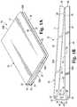
- Figure 3Ais an alternative perspective view of the electronic device 10 in a third position and Figure 3A is a side view of the electronic device 10 in the third position according to an example implementation.
- Figure 4is a perspective view of the electronic device cover 15 according to an example implementation.
- the cover 15includes a first section 17, a second section 19, and a third section 21.
- the first section 17is connected to the second section 19 by a first connection mechanism 23 and the third section 21 is connected to the second section 19 by a second connection mechanism 25.
- the cover 15may be constructed from thermoplastic polyurethane ("TPU"), metal, plastic, fiber resin, or another suitable material.
- TPUthermoplastic polyurethane
- the covermay include resistance increasing components (i.e., legs, not shown) on a bottom surface of sections 17 and 21 for placing the electronic device on a surface such as a desk or table.
- the cover 15may also include components of the electronic device 10 such as: I/O port(s), processor, battery, memory, antenna(s), speaker, camera, accelerometer(s), sensors, printed circuit board, or other applicable components (some components are shown in Figure 4 ).
- first section 17 and the third section 21are substantially flat.
- sections 17 and 21may have different forms that are sufficient to movably connect them to the second section 19, to support the flexible display 30, and to transition the flexible display 30 between different orientations.
- the second section 19may have a width that is substantially less than the width of sections 17 and 21 such as the cover 15 has the form of a binder.
- Sections 17, 19, and 21may be constructed as one single piece or may be constructed as separate pieces that are attached to each other (e.g., via connection mechanisms 23 and 25).
- sections 17, 19, and 21may include removable outer surfaces that can be replaced by the user. For instance, a user may replace the outer surface of sections 17, 19, and 21 with surfaces that have different colors or include images in order to customize the cover 15.
- the first section 17 and the third section 21may be substantially rectangular but in other implementations they may have different shapes.
- the first section 17includes an external surface 32, an internal surface 34, a top surface 36, a bottom surface 38, and two side surfaces 39A-39B.
- the first sectionmay include at least one antenna 60 and a main PCB 62 (i.e., a motherboard including CPU, memory, etc. (not shown) that connects with a flexible PCB 64 extending through sections 19 and 21.
- the first section 17may include additional elements.
- the second section 19includes an external surface 40, an internal surface 42, a top surface 44, a bottom surface 46, and two side surfaces 47A-47B.
- the second sectionincludes at least one port 66, a camera 68, a speaker (not shown), and a portion of the flexible PCB 64.
- the flexible PCBalso extends through all the sections of the cover 15. In other implementations, the second section 19 may include additional elements.
- the at least one port 66may include any type of a port or an opening that allows for communication and/or interaction with external devices or objects.
- the port 66may include an HDMI port (e.g., full size HDMI, mini HDMI, micro HDMI etc.), a USB port (e.g., full size USB, mini USB, micro USB, power USB), a Thunderbolt port, a memory card reader slot, a DC power jack, a RJ-45 port, an audio jack or port (e.g., for headphone, microphones, etc.) or any other type of port.
- the electronic device 10may also include various buttons or keys (e.g., power, volume, etc.), as well as different displays or indicators (e.g., to indicate charging, low battery, etc.).
- the cover 15may further include electronic elements or circuits (not shown) that can facilitate the operation of the display 30 and the interaction between the electronic device 10 and any external devices.
- the port 66provides enhanced connectivity of the electronic device 10.
- the electronic devicemay receive power through the port 66 and a user may power charge the electronic device 10.
- the portallows for a full spectrum of connection and communication capabilities between the device 10 and a variety of external accessories (e.g., a speaker, a mouse, etc.).
- the third section 21includes an external surface 48, an internal surface 50, a top surface 52, a bottom surface 54, and two side surfaces 55A-55B.
- the third section 21includes a battery 70, a data storage 72 (e.g., hard disk drive, solid-state drive, solid state, hybrid drive, etc.), and a portion of the flexible PCB 64.
- the third section 21may include additional elements.
- Sections 17, 19, and 21are movably connected to facilitate the transition of the device 10 between different positions (open, closed, etc.).
- the bottom surface 38 of the first section 17connects to the top surface 44 of the second section 19 (e.g., via connection mechanism 23) and the bottom surface 46 of the second section 19 connects to the bottom surface 54 of the third section 21 (e.g., via connection mechanism 25).
- connection mechanisms 23 and 25are synchronized to position the first section 17 and the third section 21 at matching acute angles to the second section 19 and to transition the flexible display 30 to a plurality of different orientations.
- the acute angle between the second section 19 and sections 17 and 21i.e., at surfaces 37/44 and 46/54) may vary depending on the position of the case 15 (i.e., open, closed, or intermediate).
- connection mechanisms 23 and 25connect sections 17 and 21 with the second section 19 and enable adjustment of the position of sections 17 and 21 and, consequently, of the flexible display 30.
- each of the connection mechanisms 23 and 25includes a hinge extending along the length of sections 17, 19, and 21.
- the connection mechanisms 23 and 25may include a greater number of hinges (two, four, etc.) that extend along the length of sections 17, 19, and 21.
- each of the hingesmay include two elongated barrels that interact with one another to adjust the position of sections 17 and 21. The elongated barrels may be securely engaged to each other with a support mechanism (e.g., a bracket, etc.) that may be positioned at different sections of the barrels.
- a support mechanisme.g., a bracket, etc.
- each of the barrelsmay include at least one gear that interacts with a gear in the other barrel to move the sections of the case 15 in different positions.
- Each of the barrelsmay also include at last one pin that securely connects the hinges to the sections of the cover 15.
- the connection mechanisms 23 and 25are synchronized to rotate along two parallel axes to transition the flexible display attached to the cover 15 between different orientations (e.g., at least between a first orientation and a second orientation).
- the electronic device 10may include other types of connection mechanisms to movably connect the sections of the case 15.
- Such mechanismsmay include magnets, fasteners, clips, straps, pins, links, springs, hoops, or any other mechanism or combination of mechanisms that allows for a secure attachment and adjustment of sections 17 and 21.
- connection mechanismthere is always a strong synchronized movable connection between sections 17 and 21 and section 19 of the cover 15. This synchronized operation of the connection mechanisms 23 and 25 allows a user to adjust the positions of the at least sections 17 and 21 and, consequently, to change the orientation of the flexible display 30 that is attached to the cover 15.
- sections 17 and 21may open or "unfold” at the same rate but in opposite directions relative to the second section 19 until the flexible display 30 is fully open (e.g., it is substantially flat).
- sections 17 and 21may be synchronized to "fold" or close with the same rate.
- the flexible display 30 of the electronic device 10has a seamless configuration (i.e., it is constructed from one whole display piece that is extends along the length of the cover 15 without any interruptions).
- the flexible display 30includes a top surface 74 and a bottom surface 76.
- the display 30is not fixed as the traditional flat screen displays but can transition between different orientations when a force is applied to the cover 15 supporting the display.
- the flexible display 45may be an LCD (Liquid Crystal Display), OLED (organic light emitting display), an e-paper display, or another type of flexible display that can bend and transition between orientations.
- the displaymay be a touchscreen display that can be controlled by the user through simple or multi-touch gestures by touching the screen with at least one finger.
- the display 30may include a protective layer, a touch layer, an air gap layer, and a display layer (not shown).
- the flexible display 30is attached to at least a portion of the first section 17 and a portion of the third section 21 (e.g., via an adhesive or any suitable connection mechanism). For example, at least two opposite portions of the bottom surface 76 of the flexible display 30 are attached to portions 57 and 59 of the first and the third sections 17 and 21 (shown in Figures 2A-B and 3A-B ).
- the flexible display 30may not be attached to entire area of the internal surfaces 34 and 50 or to the second section 19. That way, the display 30 can curve along an axis parallel to the length of second section 19 to transition between different orientations without completely bending (i.e., folding flat) the display 30.
- a portion of the flexible display 30may be attached to the internal surface 42 of the second section 19.
- an edge of the display 30may be attached to a center portion on the internal surface 42 of the second section 19.
- the flexible display 30may be positioned in multiple orientations.
- the display 30may be positioned in a first orientation when the first section 17 and the third sections 19 are in a plane and in a second orientation when the first and the third sections are in different planes.
- the electronic device 10in the first orientation, is at a fully open position where the flexible display 30 is substantially flat ( Figures 3A-3B ). In that orientation, the first section 17 and the third section 21 are in the same plane.
- the second section 19may be in the same pane as sections 17 and 21.
- the usermay utilize the device 10 as a media source (i.e., to watch movies, etc.) or as a working source (i.e., to perform various task or operations on the device).
- the electronic device 10In the second orientation, the electronic device 10 is in a closed position where a first portion 78 of the top surface 74 of the flexible display 30 is in contact with an opposite second portion 80 of the top surface 74.
- the first section 17 and the third section 21are in different planes.
- the second sectionis also in a different plane in relation to sections 17 and 21.
- the first connection mechanisms 23 and 25are synchronized to rotate along two parallel axes (i.e., the axes of mechanisms 23 and 25) and to move the first section 17 and the third section 21 that support the display 30.
- the flexible display 30in the second orientation, is transitioned into two approximately equal halves, where the diagonal length of each of the halves is substantially half of the diagonal length of the flexible display 30 when the display is in the first orientation ( Figures 3A-3B ).
- first orientationi.e., in an open position
- the diagonal length of the flexible display 30is approximately double the diagonal length of each of the halves.
- the diagonal length of the flexible display 30 in the first orientationmay be between 13 cm (5 inches) and 51 cm (20 inches), where other lengths are also possible.
- the diagonal length of each of the halves when the device is in the second orientationmay be between 6.4 cm (2.5 inches) and 25 cm (10 inches).
- the sizes of the two halves of the display 30may be different such as the diagonal length of each of the halves may be more or less than half of the diagonal length of the flexible display 30 when the display is in the first orientation.
- the flexible displaycurves along an axis parallel to the length of second section 19 (i.e., an axis parallel to the axes of rotation of connection mechanism 23 and 25) to transition into the two halves when the user moves sections 17 and 21 of the cover 15.
- the configuration of the device 10allows a user to "fold" the cover 15 and the display 30 together when the device is not used. That way, the electronic device 10 becomes smaller in size and the display 30 is protected during transportation of the device 10.
- the electronic device 10can expand its display size approximately two times when it is fully open and substantially flat as compared to the closed position.
- connection mechanisms 23 and 25are further synchronized to position the first section 17 and the third section 21 at matching acute angles in relation to the second section 19. Because the mechanisms 23 and 25 are synchronized, they open evenly across the two separate axes of mechanisms 23 and 25. Thus, the operation of the connection mechanisms 23 and 25 transitions the flexible display 30 to a plurality of different third orientations where the first portion 78 of the top surface 74 of the flexible display 30 is not in contact with the second portion 80 of the top surface 74.
- Figures 2A and 2Billustrate one example of the third orientation of the display 30 where the display is transitioning from the first orientation (i.e., open position) to the second orientation (i.e., closed position).
- the display 30may be adjusted to various other third orientations that are positioned between the first and the second orientations.
- the first section 17 and the third section 21are in different planes.
- the flexible display 30curves along an axis parallel to the length of second section 19 (i.e., an axis parallel to the axes of rotation of connection mechanism 23 and 25) to transition into the two halves when the display 30 is in any of the plurality of third orientations.
- the proposed configuration of the device 10allows a user to view and use the electronic device 10 in a plurality of different orientations without the hassle of adjusting any supporting elements of the device 10 (e.g., stand, etc.). Further, the plurality of elements embedded in the cover 15 (e.g., ports, speakers, etc.) of the proposed device 10 enhance the operating capabilities of the electronic device 10 and users may operate the electronic device 10 as their main device.
- connection mechanisms 23 and 25 of the cover 15are synchronized to rotate along two parallel axes to adjust the positions of at least the first section 17 and the third section 21 from a first orientation, where the internal surface 34 of the first section 17 is in contact with an internal surface 50 of the third section 21, to at least a second orientation where the internal surface 34 of the first section 17 is in not in contact with the internal surface 50 of the third section 21.
- the cover 15may further include at least one attachment mechanism (e.g., adhesive, mechanical attachment, etc., not shown) to attach a flexible display (e.g., the display 30) to at least a portion of the first section 17 and a portion the third section 21 of the cover.
- at least one attachment mechanisme.g., adhesive, mechanical attachment, etc., not shown
Landscapes
- Engineering & Computer Science (AREA)
- Computer Hardware Design (AREA)
- Theoretical Computer Science (AREA)
- Physics & Mathematics (AREA)
- Human Computer Interaction (AREA)
- General Engineering & Computer Science (AREA)
- General Physics & Mathematics (AREA)
- Mathematical Physics (AREA)
- Telephone Set Structure (AREA)
- Casings For Electric Apparatus (AREA)
- Devices For Indicating Variable Information By Combining Individual Elements (AREA)
Description
- Increasing number of today's users carry at least one portable electronic device that is equipped with a diverse set of functions. These devices can communicate with each other, reach the Internet, perform different tasks, or access various services through networks. These portable electronic devices have become essential personal accessories, connecting users to friends, work, and entertainment.
- Electronic devices including flexible displays are described in
US 2010/0232100 A1 ,US 2011/286157A1 ,KR 2010 0025360 A WO 2013/033479A1 ,US 2012/162049 A1 orUS 2010/164837 A1 .US 2004/0049743 A1 shows a foldable device with a communication port and a camera located in its hinge. Figure 1A is a perspective view of an electronic device in a first position according to an example implementation.Figure 1B is a side view of the electronic device ofFigure 1A according to an example implementation.Figure 2A is an alternative perspective view of the electronic device ofFigure 1A in a second position according to an example implementation.Figure 2B is a side view of the electronic device in the second position according to an example implementation.Figure 3A is an alternative perspective view of the electronic device ofFigure 1A in a third position according to an example implementation.Figure 3B is a side view of the electronic device in the third position according to an example implementation.Figure 4 is a perspective view of an electronic device cover according to an example implementation.- With the recent improvements in technology, portable electronic devices (e.g., tablets, laptops, smartphones, etc.) continue to play an increasing role in people's life.
- Portable electronic devices come in different sizes, forms, and may include different technical features. Due to the proliferation of electronic devices, their technological capabilities are continuously increasing. Regardless of the type of portable electronic devices, one of the main advantages of these devices is portability. Thus, users generally carry these devices on a daily basis between many different locations. This creates a risk of damaging the portable devices if the devices are scratched, dropped, stepped on, hit, etc. Consequently, it is desirable that these devices are well protected.
- Many users of such portable electronic device may use protective accessories (e.g., bags, cases, covers, etc.) when carrying these devices. However, such protective accessories may be inconvenient to carry and they may not securely engage the portable electronic devices when the devices are inserted in these accessories. A secure attachment between the portable electronic devices and the protective accessories is very important because users generally carry the portable electronic devices by holding the protective accessories (or at least a portion of the protective accessories). Thus, if the electronic devices are not securely connected to the protective accessories, the electronic device may detach from the protective accessory and may be damaged.
- In addition, many of the recently manufactured portable electronic devices (e.g., tablets, smartphones, etc.) include larger and more sophisticated processors, hard drives, and memories as compared to similar older devices. Therefore, these devices now have improved operating capabilities and may be used to perform many functions or tasks that are usually performed with desktop computers. Many users now desire to utilize these efficient portable electronic device as their primary office or home devices. In addition, these devices continue to be heavily used for entertaining (e.g., watching movies, browsing the Internet, etc.). Thus, users generally prefer portable electronic devices with larger displays that are more convenient for work and/or entertainment purposes. However, since one of the main advantages of these devices is portability, it is difficult to manufacture portable devices with larger displays that can easily be protected during transportation.
- Further, there is a tendency that many of the new portable electronic devices are constructed to be very thin. This is due to user's demand for light portable electronic devices that are easy to carry and do not take up too much space. Constructing a thin portable electronic device usually means that the device includes a housing with a very small width. One disadvantage of constructing very thin portable electronic devices is that such devices can not include many standard input/output ("I/O") ports (e.g., a High-Definition Multimedia Interface (HDMI) port, a Universal Serial Bus (USB) port, etc.). In addition, most current portable electronic devices have very limited space for memory and speakers due to the small width of the devices. That limits the functionality of the portable electronic devices and makes them less desirable.
- With the rapid development of flexible displays, it is desirable to develop portable electronic device that address the above-identified issues and that offers consumers a useful, reliable, and easy to protect device. Flexible displays generally include electronic displays that are not fixed as the traditional flat screen displays but can bend when a force is applied to a portion of the flexible display.
- The present description is directed to an electronic computing device and to cover for an electronic computing device. The description proposes a novel and previously unforeseen electronic computing device that includes a seamless flexible display and can transition the display between various orientations. The electronic device allows the display to transition from a closed position (where the display is protected) to an open position (e.g., where the display is substantially flat), and to various positions/orientations in between. Very often, users of portable electronic devices may want to switch the orientation or the position of the display. However, in many cases, switching the operation of the display involves repositioning a supporting accessory for the device (e.g., an external protective cover, a stand, etc.). This may require one or more of the following: removing the device from the case/stand, adjusting the position of the case/stand (e.g., by mechanically moving specific portions of the stand to different positions), rotating the device, and reattaching the device on the stand. Repeating this process many times throughout the day may be cumbersome to the users of such electronic devices. The proposed device eliminates this by offering a convenient way to switch the orientation of the display by simply adjusting the display and the cover supporting the display.
- The proposed electronic device offers a configuration that includes a cover that is securely attached to a seamless flexible display. The configuration allows a user to "fold" the cover and the display together when the device is not used. That way, the electronic device becomes smaller in size, can be easily transported, and the display is protected by the cover. When a user wishes to use the electronic device, the user may "unfold" the device and position the flexible display in various orientations without the need to mechanically adjust external elements (e.g., cover, stand, etc.). Due to the configuration of the device and the structure of the cover supporting the display, the electronic device can expand its display size approximately two times when is fully open and flat as compared to its closed position. That way, the offered electronic device is small, portable, and protected when needed, and, at the same time, the device can transform to a functional system with a relatively large display.
- Further, the proposed electronic device includes various elements or components. For example, the cover of the electronic device may include I/O ports, memory, camera, speakers, and other elements that provide enhanced connectivity and functional capabilities of the electronic device.
- In an example implementation, an electronic device is provided. The electronic device includes a cover and a flexible display. The cover includes a first section, a second section connected to the first section by a first connection mechanism, and a third section connected to the second section by a second connection mechanism. The flexible display is attached to at least a portion of the first section and a portion of the third section. The flexible display is positioned in a first orientation when the first and the third sections are in a plane and in a second orientation when the sections are in different planes.
- In another example implementation, a portable computing device is provided. The portable computing device includes a seamless flexible display, a first section supporting at least a first portion of the flexible display, a second section connected to the first section by a first hinge, and a third section supporting at least a second portion of the flexible display. The third section is connected to the second section by a second hinge. The hinges are synchronized to rotate at least the first section and the second section and to convert the seamless flexible display between different orientations such as the flexible display transitions between a closed position, where the display forms two approximately equal halves, into an open position where a diagonal length of the flexible display is approximately double a diagonal length of each of the halves
- In yet another example implementation an electronic device cover is provided. The cover includes a first section, a second section connected to the first section by a first connection mechanism, and a third section connected to the second section by a second connection mechanism. The connection mechanisms are synchronized to rotate along two parallel axes to adjust positions of at least the first section and the third section from a first orientation, where an internal surface of the first section is in contact with an internal surface of the second section, to at least a second orientation where the internal surface of the first section is in not in contact with the internal surface of the second section.
- As used herein, the terms "portable electronic device," "electronic device," and "portable computing device" may be used interchangeably and refer to any one of various tablets, smartphones, cellular telephones, personal data assistants (PDA's), laptops, computers, and other similar electronic devices that are generally movable and include at least a housing, a display screen, and a processor.
- As used herein, the term "port" refers to any one of various openings that may be included in an electronic device and may include any of I/O or communication ports, multimedia ports, power ports, audio ports or jacks, memory card readers, or any other openings or ports that allow for communication and/or interaction with external devices or objects.
- In the following detailed description, reference is made to the accompanying drawings, which form a part hereof, and in which is shown by way of illustration specific examples in which the disclosed subject matter may be practiced. It is to be understood that other examples may be utilized and structural or logical changes may be made without departing from the scope of the present disclosure. The following detailed description, therefore, is not to be taken in a limiting sense, and the scope of the present disclosure is defined by the appended claims. Also, it is to be understood that the phraseology and terminology used herein is for the purpose of description and should not be regarded as limiting. The use of "including," "comprising" or "having" and variations thereof herein is meant to encompass the items listed thereafter and equivalents thereof as well as additional items. It should also be noted that a plurality of hardware and software based devices, as well as a plurality of different structural components may be used to implement the disclosed methods and systems.
- With reference to the figures,
Figure 1A is a perspective view of an electronic device 10 (also called an electronic computing device) in a first position, andFigure 1B is a side view of theelectronic device 10 in the first position according to an example implementation. Theelectronic device 10 includes acover 15 and aflexible display 30 attached to at least a portion of thecover 15. - The specific details of the proposed
electronic device 10 are explained in relation toFigures 1A-4 .Figure 2A is an alternative perspective view of theelectronic device 10 in a second position andFigure 2B is a side view of theelectronic device 10 in the second position according to an example implementation.Figure 3A is an alternative perspective view of theelectronic device 10 in a third position andFigure 3A is a side view of theelectronic device 10 in the third position according to an example implementation.Figure 4 is a perspective view of theelectronic device cover 15 according to an example implementation. - As shown in
Figures 1A-4 , thecover 15 includes afirst section 17, asecond section 19, and athird section 21. Thefirst section 17 is connected to thesecond section 19 by afirst connection mechanism 23 and thethird section 21 is connected to thesecond section 19 by asecond connection mechanism 25. Thecover 15 may be constructed from thermoplastic polyurethane ("TPU"), metal, plastic, fiber resin, or another suitable material. The cover may include resistance increasing components (i.e., legs, not shown) on a bottom surface ofsections cover 15 may also include components of theelectronic device 10 such as: I/O port(s), processor, battery, memory, antenna(s), speaker, camera, accelerometer(s), sensors, printed circuit board, or other applicable components (some components are shown inFigure 4 ). - In one example, the
first section 17 and thethird section 21 are substantially flat. In other examples,sections second section 19, to support theflexible display 30, and to transition theflexible display 30 between different orientations. Thesecond section 19 may have a width that is substantially less than the width ofsections cover 15 has the form of a binder.Sections connection mechanisms 23 and 25). In addition,sections sections cover 15. - With continued reference to
Figures 1A-4 , thefirst section 17 and thethird section 21 may be substantially rectangular but in other implementations they may have different shapes. Thefirst section 17 includes anexternal surface 32, aninternal surface 34, atop surface 36, abottom surface 38, and twoside surfaces 39A-39B. The first section may include at least oneantenna 60 and a main PCB 62 (i.e., a motherboard including CPU, memory, etc. (not shown) that connects with aflexible PCB 64 extending throughsections first section 17 may include additional elements. - The
second section 19 includes anexternal surface 40, aninternal surface 42, atop surface 44, abottom surface 46, and twoside surfaces 47A-47B. The second section includes at least oneport 66, a camera 68, a speaker (not shown), and a portion of theflexible PCB 64. The flexible PCB also extends through all the sections of thecover 15. In other implementations, thesecond section 19 may include additional elements. - The at least one
port 66 may include any type of a port or an opening that allows for communication and/or interaction with external devices or objects. For example, theport 66 may include an HDMI port (e.g., full size HDMI, mini HDMI, micro HDMI etc.), a USB port (e.g., full size USB, mini USB, micro USB, power USB), a Thunderbolt port, a memory card reader slot, a DC power jack, a RJ-45 port, an audio jack or port (e.g., for headphone, microphones, etc.) or any other type of port. Theelectronic device 10 may also include various buttons or keys (e.g., power, volume, etc.), as well as different displays or indicators (e.g., to indicate charging, low battery, etc.). Thecover 15 may further include electronic elements or circuits (not shown) that can facilitate the operation of thedisplay 30 and the interaction between theelectronic device 10 and any external devices. - The
port 66 provides enhanced connectivity of theelectronic device 10. For example, the electronic device may receive power through theport 66 and a user may power charge theelectronic device 10. In addition, the port allows for a full spectrum of connection and communication capabilities between thedevice 10 and a variety of external accessories (e.g., a speaker, a mouse, etc.). - The
third section 21 includes anexternal surface 48, aninternal surface 50, atop surface 52, abottom surface 54, and twoside surfaces 55A-55B. Thethird section 21 includes abattery 70, a data storage 72 (e.g., hard disk drive, solid-state drive, solid state, hybrid drive, etc.), and a portion of theflexible PCB 64. In other implementations, thethird section 21 may include additional elements. Sections device 10 between different positions (open, closed, etc.). Thebottom surface 38 of thefirst section 17 connects to thetop surface 44 of the second section 19 (e.g., via connection mechanism 23) and thebottom surface 46 of thesecond section 19 connects to thebottom surface 54 of the third section 21 (e.g., via connection mechanism 25). Thus,connection mechanisms first section 17 and thethird section 21 at matching acute angles to thesecond section 19 and to transition theflexible display 30 to a plurality of different orientations. The acute angle between thesecond section 19 andsections 17 and 21 (i.e., at surfaces 37/44 and 46/54) may vary depending on the position of the case 15 (i.e., open, closed, or intermediate).- The
connection mechanisms sections second section 19 and enable adjustment of the position ofsections flexible display 30. In one example, each of theconnection mechanisms sections connection mechanisms sections sections case 15 in different positions. Each of the barrels may also include at last one pin that securely connects the hinges to the sections of thecover 15. Thus, theconnection mechanisms cover 15 between different orientations (e.g., at least between a first orientation and a second orientation). - In other examples, the
electronic device 10 may include other types of connection mechanisms to movably connect the sections of thecase 15. Such mechanisms may include magnets, fasteners, clips, straps, pins, links, springs, hoops, or any other mechanism or combination of mechanisms that allows for a secure attachment and adjustment ofsections sections section 19 of thecover 15. This synchronized operation of theconnection mechanisms least sections flexible display 30 that is attached to thecover 15. In other words,sections second section 19 until theflexible display 30 is fully open (e.g., it is substantially flat). In addition,sections - In one example, the
flexible display 30 of theelectronic device 10 has a seamless configuration (i.e., it is constructed from one whole display piece that is extends along the length of thecover 15 without any interruptions). Theflexible display 30 includes atop surface 74 and abottom surface 76. As explained in additional detail below, thedisplay 30 is not fixed as the traditional flat screen displays but can transition between different orientations when a force is applied to thecover 15 supporting the display. The flexible display 45 may be an LCD (Liquid Crystal Display), OLED (organic light emitting display), an e-paper display, or another type of flexible display that can bend and transition between orientations. In one example, the display may be a touchscreen display that can be controlled by the user through simple or multi-touch gestures by touching the screen with at least one finger. Thedisplay 30 may include a protective layer, a touch layer, an air gap layer, and a display layer (not shown). - The
flexible display 30 is attached to at least a portion of thefirst section 17 and a portion of the third section 21 (e.g., via an adhesive or any suitable connection mechanism). For example, at least two opposite portions of thebottom surface 76 of theflexible display 30 are attached toportions third sections 17 and 21 (shown inFigures 2A-B and 3A-B ). Thus, theflexible display 30 may not be attached to entire area of theinternal surfaces second section 19. That way, thedisplay 30 can curve along an axis parallel to the length ofsecond section 19 to transition between different orientations without completely bending (i.e., folding flat) thedisplay 30. That configuration of thecover 15 and thedisplay 30 protects the surface of thedisplay 30 from a potential damage and allows for easier transition between the different orientations of thedisplay 30. In alternative implementations, a portion of theflexible display 30 may be attached to theinternal surface 42 of thesecond section 19. For instance, an edge of thedisplay 30 may be attached to a center portion on theinternal surface 42 of thesecond section 19. - Due to the attachment of the
flexible display 30 to thecover 15 and to the movable configuration of thecover 15, theflexible display 30 may be positioned in multiple orientations. For example, thedisplay 30 may be positioned in a first orientation when thefirst section 17 and thethird sections 19 are in a plane and in a second orientation when the first and the third sections are in different planes. In one implementation, in the first orientation, theelectronic device 10 is at a fully open position where theflexible display 30 is substantially flat (Figures 3A-3B ). In that orientation, thefirst section 17 and thethird section 21 are in the same plane. In addition, thesecond section 19 may be in the same pane assections device 10 as a media source (i.e., to watch movies, etc.) or as a working source (i.e., to perform various task or operations on the device). - In the second orientation, the
electronic device 10 is in a closed position where afirst portion 78 of thetop surface 74 of theflexible display 30 is in contact with an oppositesecond portion 80 of thetop surface 74. As shown inFigures 1A-1B , in the second orientation, thefirst section 17 and thethird section 21 are in different planes. In addition, the second section is also in a different plane in relation tosections flexible display 30 between at least the first orientation and the second orientation, thefirst connection mechanisms mechanisms 23 and 25) and to move thefirst section 17 and thethird section 21 that support thedisplay 30. - As shown in
Figures 1A-1B , in the second orientation, theflexible display 30 is transitioned into two approximately equal halves, where the diagonal length of each of the halves is substantially half of the diagonal length of theflexible display 30 when the display is in the first orientation (Figures 3A-3B ). In other words, in first orientation (i.e., in an open position) the diagonal length of theflexible display 30 is approximately double the diagonal length of each of the halves. For example, the diagonal length of theflexible display 30 in the first orientation may be between 13 cm (5 inches) and 51 cm (20 inches), where other lengths are also possible. Thus, the diagonal length of each of the halves when the device is in the second orientation may be between 6.4 cm (2.5 inches) and 25 cm (10 inches). In other implementations, the sizes of the two halves of thedisplay 30 may be different such as the diagonal length of each of the halves may be more or less than half of the diagonal length of theflexible display 30 when the display is in the first orientation. In the second orientation, the flexible display curves along an axis parallel to the length of second section 19 (i.e., an axis parallel to the axes of rotation ofconnection mechanism 23 and 25) to transition into the two halves when the user movessections cover 15. - Therefore, the configuration of the
device 10 allows a user to "fold" thecover 15 and thedisplay 30 together when the device is not used. That way, theelectronic device 10 becomes smaller in size and thedisplay 30 is protected during transportation of thedevice 10. In addition, theelectronic device 10 can expand its display size approximately two times when it is fully open and substantially flat as compared to the closed position. - The
connection mechanisms first section 17 and thethird section 21 at matching acute angles in relation to thesecond section 19. Because themechanisms mechanisms connection mechanisms flexible display 30 to a plurality of different third orientations where thefirst portion 78 of thetop surface 74 of theflexible display 30 is not in contact with thesecond portion 80 of thetop surface 74.Figures 2A and 2B illustrate one example of the third orientation of thedisplay 30 where the display is transitioning from the first orientation (i.e., open position) to the second orientation (i.e., closed position). In addition, thedisplay 30 may be adjusted to various other third orientations that are positioned between the first and the second orientations. In the plurality of the third orientations, thefirst section 17 and thethird section 21 are in different planes. Theflexible display 30 curves along an axis parallel to the length of second section 19 (i.e., an axis parallel to the axes of rotation ofconnection mechanism 23 and 25) to transition into the two halves when thedisplay 30 is in any of the plurality of third orientations. - Therefore, the proposed configuration of the
device 10 allows a user to view and use theelectronic device 10 in a plurality of different orientations without the hassle of adjusting any supporting elements of the device 10 (e.g., stand, etc.). Further, the plurality of elements embedded in the cover 15 (e.g., ports, speakers, etc.) of the proposeddevice 10 enhance the operating capabilities of theelectronic device 10 and users may operate theelectronic device 10 as their main device. - Some of the advantages described above in relation to the
electronic device 10 also apply to thecover 15 shown inFigure 4 . In particular, theconnection mechanisms cover 15 are synchronized to rotate along two parallel axes to adjust the positions of at least thefirst section 17 and thethird section 21 from a first orientation, where theinternal surface 34 of thefirst section 17 is in contact with aninternal surface 50 of thethird section 21, to at least a second orientation where theinternal surface 34 of thefirst section 17 is in not in contact with theinternal surface 50 of thethird section 21. Thecover 15 may further include at least one attachment mechanism (e.g., adhesive, mechanical attachment, etc., not shown) to attach a flexible display (e.g., the display 30) to at least a portion of thefirst section 17 and a portion thethird section 21 of the cover.
Claims (7)
- An electronic device (10) comprising:a cover (15) includinga first section (17),a second section (19) connected to the first section (17) by a first connection mechanism (23), anda third section (21) connected to the second section (19) by a second connection mechanism (25);a flexible display (30) attached to at least a portion of the first section (17) and a portion of the third section (21), the flexible display (30) being in a first position when the first and the third sections (17, 21) are aligned in a plane and in a second position when the first and the third sections (17, 21) are in different planes;a battery (70) embedded in a section of the cover (15);a communication port (66) embedded in the second section (19) between the first connection mechanism (23) and the second connection mechanism (25) at one of two side surfaces (47A, 47B);a printed circuit board (64) extending through the first, second and third sections (17, 19, 21) of the cover (15); anda camera (68) positioned in the second section (19) between the first connection mechanism (23) and the second connection mechanism (25).
- The electronic device (10) of claim 1, wherein in the first position the flexible display (30) is substantially flat, and wherein in the second position a first portion of a top surface of the flexible display (30) is in contact with a second portion of the top surface of the flexible display (30).
- The electronic device (10) of claim 1, wherein the flexible display (30) is seamless, and wherein the flexible display (30) curves along an axis to transition into the two halves when the display is in the second position or the display is in a plurality of third positions where the first and the third sections (17, 21) are in different planes and the first portion of the top surface of the flexible display (30) is not in contact with the second portion of the top surface.
- The electronic device (10) of claim 3, wherein the flexible display (30) is curved along an axis parallel to axes of rotation of the connection mechanisms (23, 25) to form the two halves when the display is in the second position or the display is in the plurality of third positions.
- The electronic device (10) of claim 1, wherein the first, second, and third sections (17, 19, 21) include removable outer surfaces that can be replaced.
- The electronic device (10) of claim 1, further comprising an attachment mechanism to attach the flexible display (30) to at least a portion of the first section (17) and a portion of the third section (21).
- The electronic device (10) of claim 1, wherein the electronic device comprises a portable computing device.
Applications Claiming Priority (1)
| Application Number | Priority Date | Filing Date | Title |
|---|---|---|---|
| PCT/US2014/013586WO2015116062A1 (en) | 2014-01-29 | 2014-01-29 | Electronic device with flexible display |
Publications (3)
| Publication Number | Publication Date |
|---|---|
| EP3100130A1 EP3100130A1 (en) | 2016-12-07 |
| EP3100130A4 EP3100130A4 (en) | 2017-10-18 |
| EP3100130B1true EP3100130B1 (en) | 2020-08-05 |
Family
ID=53757472
Family Applications (1)
| Application Number | Title | Priority Date | Filing Date |
|---|---|---|---|
| EP14880756.3AActiveEP3100130B1 (en) | 2014-01-29 | 2014-01-29 | Electronic device with flexible display |
Country Status (4)
| Country | Link |
|---|---|
| US (1) | US10013020B2 (en) |
| EP (1) | EP3100130B1 (en) |
| CN (1) | CN105900037B (en) |
| WO (1) | WO2015116062A1 (en) |
Families Citing this family (70)
| Publication number | Priority date | Publication date | Assignee | Title |
|---|---|---|---|---|
| US9798359B2 (en) | 2014-02-21 | 2017-10-24 | Samsung Electronics Co., Ltd. | Foldable device |
| KR101727971B1 (en) | 2014-02-21 | 2017-04-18 | 삼성전자주식회사 | Foldable device |
| KR102341879B1 (en)* | 2015-01-14 | 2021-12-23 | 삼성디스플레이 주식회사 | Folderable display device |
| KR20160089164A (en)* | 2015-01-19 | 2016-07-27 | 삼성전자주식회사 | Flexible device and method for controlling shape of display thereof |
| KR102353760B1 (en)* | 2015-04-01 | 2022-01-20 | 삼성디스플레이 주식회사 | Foldable display device |
| CN106325374B (en)* | 2015-06-30 | 2024-06-18 | 联想(北京)有限公司 | Electronic device and display processing method |
| CN106708172B (en)* | 2015-07-21 | 2022-04-22 | 联想(北京)有限公司 | Electronic equipment |
| KR102348931B1 (en) | 2015-11-03 | 2022-01-11 | 삼성전자주식회사 | Method of attaching display device to exterior member for electronic device and apparatus of the same |
| USD826889S1 (en)* | 2016-02-19 | 2018-08-28 | Lg Electronics Inc. | Mobile phone |
| USD827604S1 (en)* | 2016-02-19 | 2018-09-04 | Lg Electronics Inc. | Mobile phone |
| USD828319S1 (en)* | 2016-02-19 | 2018-09-11 | Lg Electronics Inc. | Mobile phone |
| USD826203S1 (en)* | 2016-02-19 | 2018-08-21 | Lg Electronics Inc. | Mobile phone |
| USD825513S1 (en)* | 2016-02-19 | 2018-08-14 | Lg Electronics Inc. | Mobile phone |
| USD828318S1 (en)* | 2016-02-19 | 2018-09-11 | Lg Electronics Inc. | Mobile phone |
| USD807856S1 (en)* | 2016-04-01 | 2018-01-16 | Lg Electronics Inc. | Mobile phone |
| USD807854S1 (en)* | 2016-04-01 | 2018-01-16 | Lg Electronics Inc. | Mobile phone |
| USD815055S1 (en)* | 2016-04-01 | 2018-04-10 | Lg Electronics Inc. | Mobile phone |
| USD807855S1 (en)* | 2016-04-01 | 2018-01-16 | Lg Electronics Inc. | Mobile phone |
| KR101720178B1 (en)* | 2016-05-27 | 2017-03-27 | 엘지전자 주식회사 | Display device |
| KR102426512B1 (en) | 2016-06-09 | 2022-07-28 | 삼성디스플레이 주식회사 | Foldable display device |
| USD822658S1 (en)* | 2016-06-30 | 2018-07-10 | Intel Corporation | Computer notebook |
| KR102595230B1 (en)* | 2016-10-13 | 2023-10-30 | 삼성전자주식회사 | Foldable electronic device including flexible display |
| WO2018071027A1 (en)* | 2016-10-13 | 2018-04-19 | Hewlett-Packard Development Company, L.P. | Electronic desk |
| USD842833S1 (en)* | 2017-01-10 | 2019-03-12 | Lg Electronics Inc. | Mobile phone |
| KR102688971B1 (en)* | 2017-02-22 | 2024-07-25 | 삼성디스플레이 주식회사 | Foldable display device |
| KR102356866B1 (en)* | 2017-04-10 | 2022-02-03 | 삼성디스플레이 주식회사 | Foldable display device and method for manufacturing the same |
| WO2018198307A1 (en)* | 2017-04-28 | 2018-11-01 | シャープ株式会社 | Mobile terminal with flexible display |
| KR102416584B1 (en)* | 2017-09-18 | 2022-07-05 | 삼성디스플레이 주식회사 | Display apparatus |
| JP6453413B1 (en)* | 2017-10-04 | 2019-01-16 | レノボ・シンガポール・プライベート・リミテッド | Portable information equipment |
| CN109699151B (en) | 2017-10-20 | 2020-02-14 | 华为技术有限公司 | Film-shaped heat dissipation member, bendable display device, and terminal device |
| US11402669B2 (en) | 2018-04-27 | 2022-08-02 | Apple Inc. | Housing surface with tactile friction features |
| USD961586S1 (en)* | 2018-05-11 | 2022-08-23 | Lenovo (Beijing) Co., Ltd. | Flexible display |
| US10534406B2 (en)* | 2018-06-29 | 2020-01-14 | Intel Corporation | Dual screen electronic devices with stowable keyboards |
| US10694010B2 (en) | 2018-07-06 | 2020-06-23 | Apple Inc. | Cover sheet and incorporated lens for a camera of an electronic device |
| US11112827B2 (en) | 2018-07-20 | 2021-09-07 | Apple Inc. | Electronic device with glass housing member |
| KR102575550B1 (en)* | 2018-08-20 | 2023-09-07 | 삼성전자주식회사 | Printed circuit board including bending portion, and electronic device with the same |
| US11570290B2 (en) | 2018-08-27 | 2023-01-31 | Huawei Technologies Co. Ltd. | Mobile terminal |
| CN112005187B (en)* | 2018-08-31 | 2024-09-17 | 惠普发展公司,有限责任合伙企业 | Suspension for display |
| WO2020044171A1 (en) | 2018-08-31 | 2020-03-05 | 株式会社半導体エネルギー研究所 | Display device |
| US10642318B1 (en)* | 2018-09-14 | 2020-05-05 | Apple Inc. | Planar hinge assembly |
| US11609611B2 (en) | 2018-11-13 | 2023-03-21 | Google Llc | Cover for electronic device with flexible display |
| US11691912B2 (en) | 2018-12-18 | 2023-07-04 | Apple Inc. | Chemically strengthened and textured glass housing member |
| USD909370S1 (en)* | 2019-02-01 | 2021-02-02 | Samsung Electronics Co., Ltd. | Tablet computer |
| KR102705836B1 (en)* | 2019-02-26 | 2024-09-12 | 삼성디스플레이 주식회사 | Display apparatus |
| US11199929B2 (en) | 2019-03-21 | 2021-12-14 | Apple Inc. | Antireflective treatment for textured enclosure components |
| KR102596817B1 (en)* | 2019-04-11 | 2023-11-01 | 삼성전자주식회사 | Electronic device and method for controlling transmission power thereof |
| US11372137B2 (en) | 2019-05-29 | 2022-06-28 | Apple Inc. | Textured cover assemblies for display applications |
| US11109500B2 (en) | 2019-06-05 | 2021-08-31 | Apple Inc. | Textured glass component for an electronic device enclosure |
| US11192823B2 (en) | 2019-06-05 | 2021-12-07 | Apple Inc. | Electronic devices including laser-textured glass cover members |
| US10827635B1 (en) | 2019-06-05 | 2020-11-03 | Apple Inc. | Electronic device enclosure having a textured glass component |
| CN112309245B (en)* | 2019-07-26 | 2022-08-23 | 群创光电股份有限公司 | Foldable display device |
| TWI770577B (en)* | 2019-08-06 | 2022-07-11 | 仁寶電腦工業股份有限公司 | Data processing apparatus with adaptive display adjustment and display adjustment method |
| CN110647215B (en)* | 2019-09-29 | 2021-04-13 | 联想(北京)有限公司 | Rotating shaft and electronic equipment |
| KR102689031B1 (en)* | 2019-10-21 | 2024-07-29 | 삼성전자주식회사 | Electronic device including dustproof structure |
| WO2021080041A1 (en) | 2019-10-24 | 2021-04-29 | 엘지전자 주식회사 | Electronic device comprising speaker module |
| KR102641514B1 (en)* | 2020-02-10 | 2024-02-27 | 삼성전자주식회사 | Foldable electronic device including hinge assembly |
| US20230134745A1 (en)* | 2020-04-22 | 2023-05-04 | Hewlett-Packard Development Company, L.P. | Computing devices with hinge bars |
| CN111430443A (en)* | 2020-04-29 | 2020-07-17 | 武汉华星光电半导体显示技术有限公司 | Organic light emitting display and manufacturing method thereof |
| US11190629B1 (en)* | 2020-08-17 | 2021-11-30 | Wei Hu Koh | Sectioned wearable smartphone devices |
| US11897809B2 (en) | 2020-09-02 | 2024-02-13 | Apple Inc. | Electronic devices with textured glass and glass ceramic components |
| CN114430432B (en)* | 2020-10-29 | 2023-04-04 | 华为技术有限公司 | Folding mechanism and electronic equipment |
| US11416040B1 (en)* | 2021-03-12 | 2022-08-16 | Motorola Mobility Llc | Hinged electronic device with flexible display and heat spreader |
| US12287684B2 (en)* | 2021-07-09 | 2025-04-29 | Samsung Electronics Co., Ltd. | Electronic device including heat transfer member |
| TWI811743B (en)* | 2021-07-22 | 2023-08-11 | 仁寶電腦工業股份有限公司 | Foldable electronic device |
| USD1054394S1 (en)* | 2021-08-25 | 2024-12-17 | Lg Display Co., Ltd. | Television receiver with speaker |
| KR20230126760A (en)* | 2022-02-23 | 2023-08-31 | 삼성디스플레이 주식회사 | Display device |
| US20250294989A1 (en)* | 2022-06-14 | 2025-09-18 | c/o Sharp Display Technology Corporation | Multifaceted display device and display apparatus |
| TWD226117S (en)* | 2022-12-14 | 2023-06-21 | 宏碁股份有限公司 | Notebook computer |
| USD1070846S1 (en)* | 2023-03-29 | 2025-04-15 | Lenovo (Beijing) Limited | Portable computer |
| EP4521190A4 (en)* | 2023-07-19 | 2025-05-21 | Samsung Electronics Co., Ltd. | Foldable device including connection member for battery |
Citations (3)
| Publication number | Priority date | Publication date | Assignee | Title |
|---|---|---|---|---|
| US20040049743A1 (en)* | 2000-03-31 | 2004-03-11 | Bogward Glenn Rolus | Universal digital mobile device |
| WO2004095717A2 (en)* | 2003-04-17 | 2004-11-04 | Nokia Corporation | Bi-stable hinge and systems using same |
| US20040264118A1 (en)* | 2003-06-30 | 2004-12-30 | International Business Machines Corporation | Portable computer having a split screen and a multi-purpose hinge |
Family Cites Families (26)
| Publication number | Priority date | Publication date | Assignee | Title |
|---|---|---|---|---|
| JPH0822343A (en)* | 1994-07-07 | 1996-01-23 | Olympus Optical Co Ltd | Information processor |
| JP2001197462A (en)* | 2000-01-17 | 2001-07-19 | Nec Corp | Visual telephone equipment and visual telephone system provided with the same |
| JP4048435B2 (en)* | 2003-10-23 | 2008-02-20 | ソニー株式会社 | Electronics |
| US20070097014A1 (en)* | 2005-10-31 | 2007-05-03 | Solomon Mark C | Electronic device with flexible display screen |
| US7787917B2 (en) | 2006-12-28 | 2010-08-31 | Intel Corporation | Folding electronic device with continuous display |
| USD580432S1 (en)* | 2007-03-06 | 2008-11-11 | Samsung Electronics Co., Ltd. | Portable electronic notebook |
| TWI468897B (en)* | 2007-04-25 | 2015-01-11 | Creator Technology Bv | Electronic device |
| US8005521B2 (en)* | 2007-06-01 | 2011-08-23 | Lg Electronics Inc. | Portable terminal |
| KR101453906B1 (en)* | 2008-08-27 | 2014-10-21 | 엘지전자 주식회사 | A portable terminal and its operation control method |
| US8385055B2 (en)* | 2008-12-26 | 2013-02-26 | Industrial Technology Research Institute | Electric device and display panel thereof |
| JP2010218102A (en)* | 2009-03-16 | 2010-09-30 | Sony Corp | Electronic equipment |
| US20120236484A1 (en)* | 2009-12-01 | 2012-09-20 | Hideyuki Miyake | Foldable mobile terminal |
| KR101067587B1 (en)* | 2010-01-29 | 2011-09-27 | 주식회사 팬택 | Flexible terminal with shape conversion characteristics, shape conversion method and shape conversion device |
| TWI383343B (en) | 2010-05-21 | 2013-01-21 | Wistron Corp | Electronic device capable of providing a display panel with planar support |
| US8958201B2 (en)* | 2011-04-15 | 2015-02-17 | Blackberry Limited | Flexible mobile computing devices |
| US20120314399A1 (en) | 2011-06-07 | 2012-12-13 | Microsoft Corporation | Flexible display foldable assembly |
| US8711566B2 (en) | 2011-09-02 | 2014-04-29 | Microsoft Corporation | Expandable mobile device |
| JP5887790B2 (en)* | 2011-09-21 | 2016-03-16 | ソニー株式会社 | Display device and electronic device |
| EP2595029A1 (en)* | 2011-11-15 | 2013-05-22 | Research In Motion Limited | Handheld electronic device having a flexible display |
| TW201325374A (en)* | 2011-12-09 | 2013-06-16 | Askey Technology Jiangsu Ltd | Portable electronic device |
| CN103161819B (en)* | 2012-02-27 | 2015-04-29 | 联想(北京)有限公司 | Hinge device and electronic device comprising hinge device |
| US8896202B2 (en)* | 2012-02-28 | 2014-11-25 | Lg Electronics Inc. | Display device |
| US8971032B2 (en)* | 2012-11-02 | 2015-03-03 | Blackberry Limited | Support for a flexible display |
| KR101452871B1 (en)* | 2013-01-11 | 2014-10-22 | (주) 프렉코 | Foldable Flexible Display Device |
| KR102020659B1 (en)* | 2013-06-03 | 2019-09-11 | 삼성디스플레이 주식회사 | Foldable display device |
| US9442530B2 (en)* | 2013-12-04 | 2016-09-13 | Nokia Technologies Oy | Foldable device |
- 2014
- 2014-01-29EPEP14880756.3Apatent/EP3100130B1/enactiveActive
- 2014-01-29CNCN201480072706.7Apatent/CN105900037B/enactiveActive
- 2014-01-29USUS15/109,908patent/US10013020B2/enactiveActive
- 2014-01-29WOPCT/US2014/013586patent/WO2015116062A1/enactiveApplication Filing
Patent Citations (3)
| Publication number | Priority date | Publication date | Assignee | Title |
|---|---|---|---|---|
| US20040049743A1 (en)* | 2000-03-31 | 2004-03-11 | Bogward Glenn Rolus | Universal digital mobile device |
| WO2004095717A2 (en)* | 2003-04-17 | 2004-11-04 | Nokia Corporation | Bi-stable hinge and systems using same |
| US20040264118A1 (en)* | 2003-06-30 | 2004-12-30 | International Business Machines Corporation | Portable computer having a split screen and a multi-purpose hinge |
Also Published As
| Publication number | Publication date |
|---|---|
| EP3100130A4 (en) | 2017-10-18 |
| US10013020B2 (en) | 2018-07-03 |
| WO2015116062A1 (en) | 2015-08-06 |
| US20160334836A1 (en) | 2016-11-17 |
| EP3100130A1 (en) | 2016-12-07 |
| CN105900037B (en) | 2020-03-17 |
| CN105900037A (en) | 2016-08-24 |
Similar Documents
| Publication | Publication Date | Title |
|---|---|---|
| EP3100130B1 (en) | Electronic device with flexible display | |
| US9774135B2 (en) | Electronic device stand | |
| US10481643B2 (en) | Stacking detachable tablet | |
| EP3093730B1 (en) | Separable electronic device | |
| US11137797B2 (en) | Adjustable stand and mobile computing device system | |
| KR102167051B1 (en) | Portable device | |
| US20150198980A1 (en) | Detachable forward cradle dock | |
| US9042091B2 (en) | Portable electronic device with hinge structure | |
| US9753494B2 (en) | Electronic device accessory with at least one port | |
| US20160062395A1 (en) | Multi-screen display device | |
| CN104135831A (en) | Flexible electronic device | |
| US10595604B1 (en) | Folio including magnetic hinge for computing device | |
| US9541954B1 (en) | Portable electronic device | |
| TWM445832U (en) | Portable electronic apparatus | |
| EP3821318B1 (en) | Adjustable stand and mobile computing device system | |
| CN114495699A (en) | Supporting device of flexible display screen and terminal equipment | |
| WO2014187024A1 (en) | Reconfigurable mobile electronic devices with detachable computing and display units | |
| US9379562B2 (en) | Holding assembly for portable electronic device | |
| CN102262299A (en) | Portable electronic device | |
| TWM467351U (en) | Protective sheath | |
| CN201251734Y (en) | Electronic device with double display modules |
Legal Events
| Date | Code | Title | Description |
|---|---|---|---|
| PUAI | Public reference made under article 153(3) epc to a published international application that has entered the european phase | Free format text:ORIGINAL CODE: 0009012 | |
| STAA | Information on the status of an ep patent application or granted ep patent | Free format text:STATUS: REQUEST FOR EXAMINATION WAS MADE | |
| 17P | Request for examination filed | Effective date:20160722 | |
| AK | Designated contracting states | Kind code of ref document:A1 Designated state(s):AL AT BE BG CH CY CZ DE DK EE ES FI FR GB GR HR HU IE IS IT LI LT LU LV MC MK MT NL NO PL PT RO RS SE SI SK SM TR | |
| AX | Request for extension of the european patent | Extension state:BA ME | |
| DAX | Request for extension of the european patent (deleted) | ||
| A4 | Supplementary search report drawn up and despatched | Effective date:20170918 | |
| RIC1 | Information provided on ipc code assigned before grant | Ipc:G06F 1/16 20060101AFI20170912BHEP | |
| STAA | Information on the status of an ep patent application or granted ep patent | Free format text:STATUS: EXAMINATION IS IN PROGRESS | |
| 17Q | First examination report despatched | Effective date:20190416 | |
| RAP1 | Party data changed (applicant data changed or rights of an application transferred) | Owner name:HEWLETT-PACKARD DEVELOPMENT COMPANY, L.P. | |
| GRAP | Despatch of communication of intention to grant a patent | Free format text:ORIGINAL CODE: EPIDOSNIGR1 | |
| STAA | Information on the status of an ep patent application or granted ep patent | Free format text:STATUS: GRANT OF PATENT IS INTENDED | |
| INTG | Intention to grant announced | Effective date:20200323 | |
| GRAS | Grant fee paid | Free format text:ORIGINAL CODE: EPIDOSNIGR3 | |
| GRAA | (expected) grant | Free format text:ORIGINAL CODE: 0009210 | |
| STAA | Information on the status of an ep patent application or granted ep patent | Free format text:STATUS: THE PATENT HAS BEEN GRANTED | |
| AK | Designated contracting states | Kind code of ref document:B1 Designated state(s):AL AT BE BG CH CY CZ DE DK EE ES FI FR GB GR HR HU IE IS IT LI LT LU LV MC MK MT NL NO PL PT RO RS SE SI SK SM TR | |
| REG | Reference to a national code | Ref country code:GB Ref legal event code:FG4D | |
| REG | Reference to a national code | Ref country code:CH Ref legal event code:EP | |
| REG | Reference to a national code | Ref country code:AT Ref legal event code:REF Ref document number:1299612 Country of ref document:AT Kind code of ref document:T Effective date:20200815 | |
| REG | Reference to a national code | Ref country code:DE Ref legal event code:R096 Ref document number:602014068746 Country of ref document:DE | |
| REG | Reference to a national code | Ref country code:IE Ref legal event code:FG4D | |
| REG | Reference to a national code | Ref country code:LT Ref legal event code:MG4D | |
| REG | Reference to a national code | Ref country code:NL Ref legal event code:MP Effective date:20200805 | |
| REG | Reference to a national code | Ref country code:AT Ref legal event code:MK05 Ref document number:1299612 Country of ref document:AT Kind code of ref document:T Effective date:20200805 | |
| PG25 | Lapsed in a contracting state [announced via postgrant information from national office to epo] | Ref country code:PT Free format text:LAPSE BECAUSE OF FAILURE TO SUBMIT A TRANSLATION OF THE DESCRIPTION OR TO PAY THE FEE WITHIN THE PRESCRIBED TIME-LIMIT Effective date:20201207 Ref country code:HR Free format text:LAPSE BECAUSE OF FAILURE TO SUBMIT A TRANSLATION OF THE DESCRIPTION OR TO PAY THE FEE WITHIN THE PRESCRIBED TIME-LIMIT Effective date:20200805 Ref country code:FI Free format text:LAPSE BECAUSE OF FAILURE TO SUBMIT A TRANSLATION OF THE DESCRIPTION OR TO PAY THE FEE WITHIN THE PRESCRIBED TIME-LIMIT Effective date:20200805 Ref country code:NO Free format text:LAPSE BECAUSE OF FAILURE TO SUBMIT A TRANSLATION OF THE DESCRIPTION OR TO PAY THE FEE WITHIN THE PRESCRIBED TIME-LIMIT Effective date:20201105 Ref country code:LT Free format text:LAPSE BECAUSE OF FAILURE TO SUBMIT A TRANSLATION OF THE DESCRIPTION OR TO PAY THE FEE WITHIN THE PRESCRIBED TIME-LIMIT Effective date:20200805 Ref country code:ES Free format text:LAPSE BECAUSE OF FAILURE TO SUBMIT A TRANSLATION OF THE DESCRIPTION OR TO PAY THE FEE WITHIN THE PRESCRIBED TIME-LIMIT Effective date:20200805 Ref country code:GR Free format text:LAPSE BECAUSE OF FAILURE TO SUBMIT A TRANSLATION OF THE DESCRIPTION OR TO PAY THE FEE WITHIN THE PRESCRIBED TIME-LIMIT Effective date:20201106 Ref country code:SE Free format text:LAPSE BECAUSE OF FAILURE TO SUBMIT A TRANSLATION OF THE DESCRIPTION OR TO PAY THE FEE WITHIN THE PRESCRIBED TIME-LIMIT Effective date:20200805 Ref country code:BG Free format text:LAPSE BECAUSE OF FAILURE TO SUBMIT A TRANSLATION OF THE DESCRIPTION OR TO PAY THE FEE WITHIN THE PRESCRIBED TIME-LIMIT Effective date:20201105 Ref country code:AT Free format text:LAPSE BECAUSE OF FAILURE TO SUBMIT A TRANSLATION OF THE DESCRIPTION OR TO PAY THE FEE WITHIN THE PRESCRIBED TIME-LIMIT Effective date:20200805 | |
| PG25 | Lapsed in a contracting state [announced via postgrant information from national office to epo] | Ref country code:IS Free format text:LAPSE BECAUSE OF FAILURE TO SUBMIT A TRANSLATION OF THE DESCRIPTION OR TO PAY THE FEE WITHIN THE PRESCRIBED TIME-LIMIT Effective date:20201205 Ref country code:LV Free format text:LAPSE BECAUSE OF FAILURE TO SUBMIT A TRANSLATION OF THE DESCRIPTION OR TO PAY THE FEE WITHIN THE PRESCRIBED TIME-LIMIT Effective date:20200805 Ref country code:PL Free format text:LAPSE BECAUSE OF FAILURE TO SUBMIT A TRANSLATION OF THE DESCRIPTION OR TO PAY THE FEE WITHIN THE PRESCRIBED TIME-LIMIT Effective date:20200805 Ref country code:RS Free format text:LAPSE BECAUSE OF FAILURE TO SUBMIT A TRANSLATION OF THE DESCRIPTION OR TO PAY THE FEE WITHIN THE PRESCRIBED TIME-LIMIT Effective date:20200805 Ref country code:NL Free format text:LAPSE BECAUSE OF FAILURE TO SUBMIT A TRANSLATION OF THE DESCRIPTION OR TO PAY THE FEE WITHIN THE PRESCRIBED TIME-LIMIT Effective date:20200805 | |
| PG25 | Lapsed in a contracting state [announced via postgrant information from national office to epo] | Ref country code:RO Free format text:LAPSE BECAUSE OF FAILURE TO SUBMIT A TRANSLATION OF THE DESCRIPTION OR TO PAY THE FEE WITHIN THE PRESCRIBED TIME-LIMIT Effective date:20200805 Ref country code:SM Free format text:LAPSE BECAUSE OF FAILURE TO SUBMIT A TRANSLATION OF THE DESCRIPTION OR TO PAY THE FEE WITHIN THE PRESCRIBED TIME-LIMIT Effective date:20200805 Ref country code:EE Free format text:LAPSE BECAUSE OF FAILURE TO SUBMIT A TRANSLATION OF THE DESCRIPTION OR TO PAY THE FEE WITHIN THE PRESCRIBED TIME-LIMIT Effective date:20200805 Ref country code:DK Free format text:LAPSE BECAUSE OF FAILURE TO SUBMIT A TRANSLATION OF THE DESCRIPTION OR TO PAY THE FEE WITHIN THE PRESCRIBED TIME-LIMIT Effective date:20200805 Ref country code:CZ Free format text:LAPSE BECAUSE OF FAILURE TO SUBMIT A TRANSLATION OF THE DESCRIPTION OR TO PAY THE FEE WITHIN THE PRESCRIBED TIME-LIMIT Effective date:20200805 | |
| REG | Reference to a national code | Ref country code:DE Ref legal event code:R097 Ref document number:602014068746 Country of ref document:DE | |
| PG25 | Lapsed in a contracting state [announced via postgrant information from national office to epo] | Ref country code:AL Free format text:LAPSE BECAUSE OF FAILURE TO SUBMIT A TRANSLATION OF THE DESCRIPTION OR TO PAY THE FEE WITHIN THE PRESCRIBED TIME-LIMIT Effective date:20200805 | |
| PLBE | No opposition filed within time limit | Free format text:ORIGINAL CODE: 0009261 | |
| STAA | Information on the status of an ep patent application or granted ep patent | Free format text:STATUS: NO OPPOSITION FILED WITHIN TIME LIMIT | |
| PG25 | Lapsed in a contracting state [announced via postgrant information from national office to epo] | Ref country code:SK Free format text:LAPSE BECAUSE OF FAILURE TO SUBMIT A TRANSLATION OF THE DESCRIPTION OR TO PAY THE FEE WITHIN THE PRESCRIBED TIME-LIMIT Effective date:20200805 | |
| 26N | No opposition filed | Effective date:20210507 | |
| PG25 | Lapsed in a contracting state [announced via postgrant information from national office to epo] | Ref country code:IT Free format text:LAPSE BECAUSE OF FAILURE TO SUBMIT A TRANSLATION OF THE DESCRIPTION OR TO PAY THE FEE WITHIN THE PRESCRIBED TIME-LIMIT Effective date:20200805 | |
| PG25 | Lapsed in a contracting state [announced via postgrant information from national office to epo] | Ref country code:MC Free format text:LAPSE BECAUSE OF FAILURE TO SUBMIT A TRANSLATION OF THE DESCRIPTION OR TO PAY THE FEE WITHIN THE PRESCRIBED TIME-LIMIT Effective date:20200805 Ref country code:SI Free format text:LAPSE BECAUSE OF FAILURE TO SUBMIT A TRANSLATION OF THE DESCRIPTION OR TO PAY THE FEE WITHIN THE PRESCRIBED TIME-LIMIT Effective date:20200805 | |
| REG | Reference to a national code | Ref country code:CH Ref legal event code:PL | |
| PG25 | Lapsed in a contracting state [announced via postgrant information from national office to epo] | Ref country code:LU Free format text:LAPSE BECAUSE OF NON-PAYMENT OF DUE FEES Effective date:20210129 | |
| REG | Reference to a national code | Ref country code:BE Ref legal event code:MM Effective date:20210131 | |
| PG25 | Lapsed in a contracting state [announced via postgrant information from national office to epo] | Ref country code:FR Free format text:LAPSE BECAUSE OF NON-PAYMENT OF DUE FEES Effective date:20210131 | |
| PG25 | Lapsed in a contracting state [announced via postgrant information from national office to epo] | Ref country code:LI Free format text:LAPSE BECAUSE OF NON-PAYMENT OF DUE FEES Effective date:20210131 Ref country code:CH Free format text:LAPSE BECAUSE OF NON-PAYMENT OF DUE FEES Effective date:20210131 | |
| PG25 | Lapsed in a contracting state [announced via postgrant information from national office to epo] | Ref country code:IE Free format text:LAPSE BECAUSE OF NON-PAYMENT OF DUE FEES Effective date:20210129 | |
| PGFP | Annual fee paid to national office [announced via postgrant information from national office to epo] | Ref country code:GB Payment date:20211216 Year of fee payment:9 | |
| PG25 | Lapsed in a contracting state [announced via postgrant information from national office to epo] | Ref country code:BE Free format text:LAPSE BECAUSE OF NON-PAYMENT OF DUE FEES Effective date:20210131 | |
| PG25 | Lapsed in a contracting state [announced via postgrant information from national office to epo] | Ref country code:HU Free format text:LAPSE BECAUSE OF FAILURE TO SUBMIT A TRANSLATION OF THE DESCRIPTION OR TO PAY THE FEE WITHIN THE PRESCRIBED TIME-LIMIT; INVALID AB INITIO Effective date:20140129 | |
| PG25 | Lapsed in a contracting state [announced via postgrant information from national office to epo] | Ref country code:CY Free format text:LAPSE BECAUSE OF FAILURE TO SUBMIT A TRANSLATION OF THE DESCRIPTION OR TO PAY THE FEE WITHIN THE PRESCRIBED TIME-LIMIT Effective date:20200805 | |
| GBPC | Gb: european patent ceased through non-payment of renewal fee | Effective date:20230129 | |
| PG25 | Lapsed in a contracting state [announced via postgrant information from national office to epo] | Ref country code:GB Free format text:LAPSE BECAUSE OF NON-PAYMENT OF DUE FEES Effective date:20230129 | |
| PG25 | Lapsed in a contracting state [announced via postgrant information from national office to epo] | Ref country code:MK Free format text:LAPSE BECAUSE OF FAILURE TO SUBMIT A TRANSLATION OF THE DESCRIPTION OR TO PAY THE FEE WITHIN THE PRESCRIBED TIME-LIMIT Effective date:20200805 | |
| PG25 | Lapsed in a contracting state [announced via postgrant information from national office to epo] | Ref country code:MT Free format text:LAPSE BECAUSE OF FAILURE TO SUBMIT A TRANSLATION OF THE DESCRIPTION OR TO PAY THE FEE WITHIN THE PRESCRIBED TIME-LIMIT Effective date:20200805 | |
| PGFP | Annual fee paid to national office [announced via postgrant information from national office to epo] | Ref country code:DE Payment date:20241218 Year of fee payment:12 | |
| REG | Reference to a national code | Ref country code:DE Ref legal event code:R082 Ref document number:602014068746 Country of ref document:DE Representative=s name:NOVAGRAAF BREVETS, FR |