EP3098651B1 - Light pulse compression reflectometer - Google Patents
Light pulse compression reflectometerDownload PDFInfo
- Publication number
- EP3098651B1 EP3098651B1EP14870645.0AEP14870645AEP3098651B1EP 3098651 B1EP3098651 B1EP 3098651B1EP 14870645 AEP14870645 AEP 14870645AEP 3098651 B1EP3098651 B1EP 3098651B1
- Authority
- EP
- European Patent Office
- Prior art keywords
- optical
- port
- pulse compression
- reflectometer
- modulator
- Prior art date
- Legal status (The legal status is an assumption and is not a legal conclusion. Google has not performed a legal analysis and makes no representation as to the accuracy of the status listed.)
- Active
Links
- 230000006835compressionEffects0.000titleclaimsdescription53
- 238000007906compressionMethods0.000titleclaimsdescription53
- 230000003287optical effectEffects0.000claimsdescription122
- 238000012545processingMethods0.000claimsdescription18
- 230000010287polarizationEffects0.000claimsdescription16
- 239000000835fiberSubstances0.000claimsdescription15
- 239000013307optical fiberSubstances0.000claimsdescription14
- 238000012360testing methodMethods0.000claimsdescription9
- 238000010521absorption reactionMethods0.000claimsdescription2
- 238000013480data collectionMethods0.000claimsdescription2
- 239000004065semiconductorSubstances0.000claimsdescription2
- 230000001131transforming effectEffects0.000claimsdescription2
- 238000001514detection methodMethods0.000description21
- 238000005259measurementMethods0.000description17
- 230000001427coherent effectEffects0.000description12
- 238000010586diagramMethods0.000description9
- 238000000253optical time-domain reflectometryMethods0.000description9
- 238000002310reflectometryMethods0.000description9
- 238000010408sweepingMethods0.000description9
- 238000002168optical frequency-domain reflectometryMethods0.000description6
- 238000000034methodMethods0.000description5
- 238000002474experimental methodMethods0.000description4
- 230000001360synchronised effectEffects0.000description3
- 230000008094contradictory effectEffects0.000description2
- 238000010200validation analysisMethods0.000description2
- 230000035559beat frequencyEffects0.000description1
- 230000007812deficiencyEffects0.000description1
- 230000001419dependent effectEffects0.000description1
- 238000006073displacement reactionMethods0.000description1
- 230000005684electric fieldEffects0.000description1
- 238000001914filtrationMethods0.000description1
- 238000012423maintenanceMethods0.000description1
- 238000001579optical reflectometryMethods0.000description1
- 238000004088simulationMethods0.000description1
Images


Classifications
- G—PHYSICS
- G01—MEASURING; TESTING
- G01M—TESTING STATIC OR DYNAMIC BALANCE OF MACHINES OR STRUCTURES; TESTING OF STRUCTURES OR APPARATUS, NOT OTHERWISE PROVIDED FOR
- G01M11/00—Testing of optical apparatus; Testing structures by optical methods not otherwise provided for
- G01M11/30—Testing of optical devices, constituted by fibre optics or optical waveguides
- G01M11/31—Testing of optical devices, constituted by fibre optics or optical waveguides with a light emitter and a light receiver being disposed at the same side of a fibre or waveguide end-face, e.g. reflectometers
- G01M11/3109—Reflectometers detecting the back-scattered light in the time-domain, e.g. OTDR
- G01M11/3145—Details of the optoelectronics or data analysis
- G—PHYSICS
- G01—MEASURING; TESTING
- G01M—TESTING STATIC OR DYNAMIC BALANCE OF MACHINES OR STRUCTURES; TESTING OF STRUCTURES OR APPARATUS, NOT OTHERWISE PROVIDED FOR
- G01M11/00—Testing of optical apparatus; Testing structures by optical methods not otherwise provided for
- G01M11/30—Testing of optical devices, constituted by fibre optics or optical waveguides
- G01M11/31—Testing of optical devices, constituted by fibre optics or optical waveguides with a light emitter and a light receiver being disposed at the same side of a fibre or waveguide end-face, e.g. reflectometers
- G01M11/3109—Reflectometers detecting the back-scattered light in the time-domain, e.g. OTDR
- G01M11/3154—Details of the opto-mechanical connection, e.g. connector or repeater
- G—PHYSICS
- G01—MEASURING; TESTING
- G01M—TESTING STATIC OR DYNAMIC BALANCE OF MACHINES OR STRUCTURES; TESTING OF STRUCTURES OR APPARATUS, NOT OTHERWISE PROVIDED FOR
- G01M11/00—Testing of optical apparatus; Testing structures by optical methods not otherwise provided for
- G01M11/30—Testing of optical devices, constituted by fibre optics or optical waveguides
- G01M11/31—Testing of optical devices, constituted by fibre optics or optical waveguides with a light emitter and a light receiver being disposed at the same side of a fibre or waveguide end-face, e.g. reflectometers
- G01M11/3172—Reflectometers detecting the back-scattered light in the frequency-domain, e.g. OFDR, FMCW, heterodyne detection
Definitions
- the present inventionrelates to an optical sensing device, and in particular relates to an optical time domain reflectometer based on pulse compression of a detection pulse.
- Optical reflectometryfinds wide application in optical sensing, its working principle being: a beam of detection light is sent towards an optical fiber under test (FUT), and the intensity curve of a back scattered light detected via a photodetecter is obtained to analyze loss and breaking points in the FUT.
- Traditional optical time-domain reflectometryuses an optical pulse as the detection light, and therefore its spatial resolution is determined by the pulse width, the narrower the pulse width, the higher the spatial resolution.
- the narrower the pulse widththe smaller its energy, which implicates that the detection light is liable of being submerged in noise. [ M. K. Barnoski, M. D. Rourke, S. M. Jensen, R.T. Melville, "Optical time domain reflectometer,"Applied Optics, vol. 16, no. 9, pp. 2375-2379,1977 ].
- spatial resolution and measurement range in traditional optical time-domain technologyare mutually restrictive with each other.
- Optical frequency domain reflectometryuses continuous linear frequency modulation light as detection light, with a phase difference existing between optical signals reflected from different displacements in the fiber and the continuous linear modulation light to form optical beat frequency signals with various frequency differences. Said signals are transformed to photocurrents via a photodetecter and then mapped to frequency domains to obtain reflectometry information of the fiber. Spatial resolution of the frequency domain reflectometry depends only on the sweeping range of the linear modulation frequency, and hence there is no constraint between the spatial resolution and the measurement range.
- the measurement rangeis limited by the coherent length of the optical source, the maximum measurement range being approximately half of the coherent length, if the detection light were not to be being submerged in noise.
- D.Uttam and B.Culshaw"Precision time domain reflectometry in optical fiber systems using a frequency modulated continuous wave ranging technique,"Journal of Lightwave Technology,vol. 3, no. 5, pp. 971-977, 1985 ].
- CN 103401606 Adiscloses a coherent optical time domain reflectometer.
- Hiroyuki lida et al.discloses "high-sensitivity coherent optical time domain reflectometry employing frequency-division multiplexing" (Journal of lightwave technology, IEEE, USA, vol. 30, no. 8, 1 April 2012 (2012-04-01), pages 1121-1126, XP011430146 ).
- lida Hiroyuki et al.discloses "ultra high dynamic range coherent optical time domain reflectometry employing frequency division multiplexing", (21st international conference on optical fiber sensors, SPIE, 1000 20th ST. Bellingham WA 98225-6705 USA, vol. 7753, no. 1, 15 May 2011 (2011-05-15), pages 1-4, XP060011620 ).
- the present inventionprovides an optical pulse compression reflectometer according to independent claim 1.
- Various embodiments and improvementsare recited in dependent claims.
- the present inventionproposes an optical pulse compression reflectometer, with a higher spatial resolution than that of the traditional optical time domain reflectometry, and a longer measurement range than that of the optical frequency domain reflectometry.
- Two outputs of the optical couplerare received in said balanced photodetecter, and the output port of the balanced photodetecter is connected with said pulse compression processing module.
- the modulation frequency generating modulecomprises: a polarization controller, a linear modulation frequency voltage controlled oscillator, a waveform generator, a single sideband modulator, a second polarization controller, a first erbium-doped fiber amplifier, a Mach-Zehnder electro-optic modulator, and a second erbium-doped fiber amplifier;
- a wave output port of said waveform generatoris connected with an input port of said linear modulation frequency voltage controlled oscillator, an output port of the linear modulation frequency voltage controlled oscillator is connected with an electric signal input port of said single sideband modulator, the first output port of the optical splitter is connected with an input port of the single sideband modulator en route of the first polarization controller, an output port of the single sideband modulator is connected with an input port of said Mach-Zehnder electro-optic modulator en route successively of the second polarization controller and the erbium-doped fiber amplifier, a pulse output port of the waveform generator is connected with an electric signal input port of the Mach-Zehnder electro-optic modulator, and an output port of the Mach-Zehnder electro-optic modulator is connected with the first port of the optical directional coupler.
- the Mach-Zehnder electro-optic modulatoris an intensity modulator, a single sideband modulator or an electro-absorption modulator.
- Said pulse compression processing modulecomprises a data collector, an orthogonal modulator and a match filter, which are successively connected;
- Said data collectorcollects an electric signal outputted by the balanced photodetecter, said orthogonal modulator quadrature demodulates the collected signal, and said match filter match filters the quadrature demodulated signal.
- the data collectoris an analogue reception circuit, an analogue-digital transforming module, a data collection card, or an oscilloscope.
- the pulse compression processing moduleis an analogue signal processing circuit, a digital signal processor, or a computer software.
- Said single wavelength continuous optical sourceis a semiconductor laser, an optical fiber laser, a gas laser, or a dye laser.
- Said optical coupleris a 2 ⁇ 2 optical coupler.
- Said balanced photodetecteris a PIN diode or an APD (avalanche photodiode).
- Said optical directional coupleris an optical circulator or an optical coupler.
- the working principle of the present inventionis as follows:
- the optical sourceis split into two branches, one as reference light for coherent detection, the other one is generated to be a frequency modulation pulse to serve as detection light, which is compressed to be a narrow pulse in time domain by means of pulse compression, with compression ratio depending only on the sweeping range and the pulse width.
- a monochromatic continuous optical signal generated by the single wavelength continuous optical sourceis split by the optical splitter; one branch of the split optical signal is transformed by the frequency modulation pulse generating module to be a frequency modulation pulse to serve as detection light; the detection light is outputted from one end of the optical directional coupler to the other end thereof and to the optical fiber under test, the back scattered light or the reflected light is outputted by the optical directional coupler; an input port of the optical coupler receives the back scattered light, while the other branch of light split by the optical splitter is received as reference light in the other port of the optical coupler; two outputs of the optical coupler are received in the balanced photodetecter for the coherent detection; the pulse compression processing module conducts the pulse compression on the coherent-detected signals.
- the present inventionhas the following advantages:
- Figure 1is a schematic diagram of the optical pulse compression reflectometer of the present invention, as is shown thereon, it comprises: a single wavelength continuous optical source 1, an optical splitter 2, a modulation frequency pulse generating module 3, an optical directional coupler 5, an optical fiber under test 6, an optical coupler 9, a balanced photodetecter 10, and a pulse compression processing module 11;
- a monochromatic continuous optical signal generated by the single wavelength continuous optical source 1is split by the optical splitter 2; the modulation frequency pulse generating module 3 transforms one branch of the split optical signal to be a modulation frequency pulse to serve as a detection light 4, the first port of the optical directional coupler 5 receives the detection light 4 and outputs it via the second port thereof to the optical fiber under test 6, and at the mean time, the second port of the optical directional coupler 5 receives the back scattered light generated by the optical fiber under test 6 and outputs it out of the third port thereof.
- the second input port of the optical coupler 9receives the back scattered light, while the other branch of the split optical signal split by the optical splitter 2 is received in the first input port of the optical coupler 9 as a reference light 7; two outputs of the optical coupler 9 are received in the balanced photodetecter 10 for coherent detection; the pulse compression processing module 11 conducts pulse compression on the signal outputted from the balanced photodetecter 10.
- Figure 2shows a simulation diagram for the above process, that is, a diagram depicting the pulse compression of the pulse compression reflectometry system of the present invention, (a) showing the original pulse, and (b) showing the compressed pulse.
- the pulse widthshall be equal to the sweeping range B.
- Spatial resolution Zcould be defined as a distance between two smallest discernible events, and in time domain reflectometry, it is equal to a product of the width of a detection pulse with the light speed in the medium.
- Measurement range of a systemcould be defined as the maximum distance for maintenance of a greater event signal power over the noise power, and in time domain reflectometry, it increases as the pulse width increases.
- the pulse compression reflectometry system of the present inventionis capable of drastically increasing the measurement range by means of increasing the pulse width with the spatial resolution unchanged.
- energy originally evenly distributedis concentrated in a short time span, which increases the instantaneous power of the reflectometry signal at the event site, increases the signal/noise ratio, and further increases the measurement range.
- FIG. 3shows embodiment 1 of the modulation frequency pulse generating module of the optical pulse compression reflectometer of the present invention.
- the modulation frequency pulse generating modulecomprises: a first polarization controller 12, a linear modulation frequency voltage controlled oscillator 13, a waveform generator 14, a single sideband modulator 15, a second polarization controller 16, a first erbium-doped fiber amplifier 17, a Mach-Zehnder electro-optic modulator 18, and a second erbium-doped fiber amplifier 19.
- the waveform generator 14generates a periodical sawtooth wave to drive the linear modulation frequency voltage controlled oscillator 13, and connects the output port of the linear modulation frequency voltage controlled oscillator 13 with the electric signal input port of the single sideband modulator 15; subsequently, one branch of optical signal split by the optical splitter 2 is received in the single sideband modulator 15 en route of the first polarization controller 12; the output signal from the single sideband modulator 15 is received in the Mach-Zehnder electro-optic modulator 18 en route of the second polarization controller 16 and the first erbium-doped fiber amplifier 17; at the mean time, the waveform generator 14 generates a pulse synchronous with the periodical sawtooth wave for reception in the electric signal input port of the Mach-Zehnder electro-optic modulator 18; the output optical signal from the Mach-Zehnder electro-optic modulator 18 is generated to be the detection light
- Figure 4shows a modulation frequency pulse generating module of an optical pulse compression reflectometer nor being part of the present invention.
- the modulation frequency pulse generating modulecomprises: a waveform generator 20, a linear modulation frequency voltage controlled oscillator 21, a polarization controller 22, a single sideband modulator 23, and an erbium-doped fiber amplifier 24.
- the waveform generator 20generates two branches of optical signal, one is a periodical sawtooth wave, for reception in the electric signal input port of the linear modulation frequency voltage controlled oscillator 21; the other branch of optical signal is a periodical pulse signal, with a pulse width being equal to the period of the above periodical sawtooth wave, for reception in the enable input port of the linear modulation frequency voltage controlled oscillator 21.
- An output port of the linear modulation frequency voltage controlled oscillator 21is connected with an electric signal input port of the single sideband modulator 23; subsequently, one branch of optical signal split by the optical splitter 2 is received in the single sideband modulator 23 en route of the polarization controller 22; the output optical signal from the single sideband modulator 23 is generated to be the detection light 4 via the erbium-doped fiber amplifier 24.
- FIG. 5shows a schematic diagram of the pulse compression processing module of the optical pulse compression reflectometer of the present invention.
- the pulse compression processing modulecomprises a data collector 25, an orthogonal modulator 26 and a match filter 27, which are successively connected.
- the data collector 25collects an electric signal outputted by means of the coherent detection 8; said orthogonal modulator 26 quadrature demodulates the collected signal, and said match filter 27 match filters the quadrature demodulated signal.
- the working principle of the present inventionis as follows: For a linear modulation frequency voltage controlled oscillator, being driven by a periodical sawtooth wave, outputs a continuous wave of linear frequency sweep. For a single sideband modulator, it merely modulates an input electric signal to either the upper sideband or the lower sideband, and therefore, the frequency of the output optical signal is in linear relation with the input electric signal. In embodiment 1 of the modulation frequency pulse generating module, subsequent to reception of a continuous light of linear frequency sweep generated by the linear modulation frequency voltage controlled oscillator, the single sideband modulator will generate a continuous light of linear frequency sweep.
- the Mach-Zehnder electro-optic modulatorPass the continuous light of linear frequency sweep through the Mach-Zehnder electro-optic modulator, modulate up a pulse synchronous with the periodical sawtooth wave, and an optical pulse of linear frequency sweep will be obtained.
- the linear modulation frequency voltage controlled oscillatorreceive a pulse synchronous with the periodical sawtooth wave in an enable port of the linear modulation frequency voltage controlled oscillator, the linear modulation frequency voltage controlled oscillator will directly generate an electric pulse of linear frequency sweep.
- the single sideband modulatorsubsequent to reception of the electric pulse of linear frequency sweep generated by the linear modulation frequency voltage controlled oscillator, the single sideband modulator will directly generate an optical signal of linear frequency sweep.
Landscapes
- Physics & Mathematics (AREA)
- Optics & Photonics (AREA)
- Chemical & Material Sciences (AREA)
- Analytical Chemistry (AREA)
- General Physics & Mathematics (AREA)
- Engineering & Computer Science (AREA)
- Microelectronics & Electronic Packaging (AREA)
- Testing Of Optical Devices Or Fibers (AREA)
- Optical Communication System (AREA)
- Optical Modulation, Optical Deflection, Nonlinear Optics, Optical Demodulation, Optical Logic Elements (AREA)
Description
- The present invention relates to an optical sensing device, and in particular relates to an optical time domain reflectometer based on pulse compression of a detection pulse.
- Optical reflectometry finds wide application in optical sensing, its working principle being: a beam of detection light is sent towards an optical fiber under test (FUT), and the intensity curve of a back scattered light detected via a photodetecter is obtained to analyze loss and breaking points in the FUT. Traditional optical time-domain reflectometry uses an optical pulse as the detection light, and therefore its spatial resolution is determined by the pulse width, the narrower the pulse width, the higher the spatial resolution. However, in consideration of limitation on the output power of the optical pulse, the narrower the pulse width, the smaller its energy, which implicates that the detection light is liable of being submerged in noise. [M. K. Barnoski, M. D. Rourke, S. M. Jensen, R.T. Melville, "Optical time domain reflectometer,"Applied Optics, vol. 16, no. 9, pp. 2375-2379,1977]. Hence, spatial resolution and measurement range in traditional optical time-domain technology are mutually restrictive with each other.
- To overcome the bottlenecks in traditional optical time-domain reflectometry, optical frequency domain reflectometry is proposed. Optical frequency domain reflectometry uses continuous linear frequency modulation light as detection light, with a phase difference existing between optical signals reflected from different displacements in the fiber and the continuous linear modulation light to form optical beat frequency signals with various frequency differences. Said signals are transformed to photocurrents via a photodetecter and then mapped to frequency domains to obtain reflectometry information of the fiber. Spatial resolution of the frequency domain reflectometry depends only on the sweeping range of the linear modulation frequency, and hence there is no constraint between the spatial resolution and the measurement range. However, the measurement range is limited by the coherent length of the optical source, the maximum measurement range being approximately half of the coherent length, if the detection light were not to be being submerged in noise. [D.Uttam and B.Culshaw, "Precision time domain reflectometry in optical fiber systems using a frequency modulated continuous wave ranging technique,"Journal of Lightwave Technology,vol. 3, no. 5, pp. 971-977, 1985].
- In comparison with radar technology, traditional optical time domain reflectometry is similar to pulse radar systems, while optical frequency domain reflectometry is likened in its working mechanism to frequency modulated continuous wave radar. In radar technology, there is a pulse compression technique with no contradictory constraints between the spatial resolution and the measurement range, whose spatial resolution depends only on its sweeping range, and whose measurement range goes farther than the frequency modulated continuous wave radar. [M. A.Richards, Fundamentals of radar signal processing, McGraw-Hill Education, 2005].
- Therefore, by applying pulse compression radar techniques in optical time domain reflectometry, the contradictory constraint between spatial resolution and measurement range in traditional optical time domain reflectometry shall be overcome, superb spatial resolution of the pulse compression shall be in full display, and its measurement range shall be longer than that in the optical frequency domain reflectometry.
CN 103401606 A discloses a coherent optical time domain reflectometer.Hiroyuki lida et al. discloses "high-sensitivity coherent optical time domain reflectometry employing frequency-division multiplexing" (Journal of lightwave technology, IEEE, USA, vol. 30, no. 8, 1 April 2012 (2012-04-01), pages 1121-1126, XP011430146).lida Hiroyuki et al. discloses "ultra high dynamic range coherent optical time domain reflectometry employing frequency division multiplexing", (21st international conference on optical fiber sensors, SPIE, 1000 20th ST. Bellingham WA 98225-6705 USA, vol. 7753, no. 1, 15 May 2011 (2011-05-15), pages 1-4, XP060011620).- The present invention provides an optical pulse compression reflectometer according to
independent claim 1. Various embodiments and improvements are recited in dependent claims. - To overcome deficiency in the prior art, the present invention proposes an optical pulse compression reflectometer, with a higher spatial resolution than that of the traditional optical time domain reflectometry, and a longer measurement range than that of the optical frequency domain reflectometry.
- The technical solution of the present invention is as follows:
- An optical pulse compression reflectometer is featured to comprise: a single wavelength continuous optical source, an optical splitter, a modulation frequency pulse generating module, an optical directional coupler, an optical fiber under test, an optical coupler, a balanced photodetecter, and a pulse compression processing module;
- The above components are inter-connected in the following manner:
An output port of said single wavelength continuous optical source is connected with an input port of said optical splitter, the first output port of the optical splitter is connected with the first port of the optical directional coupler en route of the said modulation frequency pulse generating module, the second port of the optical directional coupler is connected with said optical fiber under test, the third port of the optical directional coupler is connected with the first input port of the optical coupler, and the second output port of the optical splitter is connected with the second input port of the optical coupler; - Two outputs of the optical coupler are received in said balanced photodetecter, and the output port of the balanced photodetecter is connected with said pulse compression processing module.
- The modulation frequency generating module comprises: a polarization controller, a linear modulation frequency voltage controlled oscillator, a waveform generator, a single sideband modulator, a second polarization controller, a first erbium-doped fiber amplifier, a Mach-Zehnder electro-optic modulator, and a second erbium-doped fiber amplifier;
- A wave output port of said waveform generator is connected with an input port of said linear modulation frequency voltage controlled oscillator, an output port of the linear modulation frequency voltage controlled oscillator is connected with an electric signal input port of said single sideband modulator, the first output port of the optical splitter is connected with an input port of the single sideband modulator en route of the first polarization controller, an output port of the single sideband modulator is connected with an input port of said Mach-Zehnder electro-optic modulator en route successively of the second polarization controller and the erbium-doped fiber amplifier, a pulse output port of the waveform generator is connected with an electric signal input port of the Mach-Zehnder electro-optic modulator, and an output port of the Mach-Zehnder electro-optic modulator is connected with the first port of the optical directional coupler.
- The Mach-Zehnder electro-optic modulator is an intensity modulator, a single sideband modulator or an electro-absorption modulator.
- Said pulse compression processing module comprises a data collector, an orthogonal modulator and a match filter, which are successively connected;
- Said data collector collects an electric signal outputted by the balanced photodetecter, said orthogonal modulator quadrature demodulates the collected signal, and said match filter match filters the quadrature demodulated signal.
- The data collector is an analogue reception circuit, an analogue-digital transforming module, a data collection card, or an oscilloscope.
- The pulse compression processing module is an analogue signal processing circuit, a digital signal processor, or a computer software.
- Said single wavelength continuous optical source is a semiconductor laser, an optical fiber laser, a gas laser, or a dye laser.
- Said optical coupler is a 2×2 optical coupler.
- Said balanced photodetecter is a PIN diode or an APD (avalanche photodiode).
- Said optical directional coupler is an optical circulator or an optical coupler.
- The working principle of the present invention is as follows:
The optical source is split into two branches, one as reference light for coherent detection, the other one is generated to be a frequency modulation pulse to serve as detection light, which is compressed to be a narrow pulse in time domain by means of pulse compression, with compression ratio depending only on the sweeping range and the pulse width. To be more specific, a monochromatic continuous optical signal generated by the single wavelength continuous optical source is split by the optical splitter; one branch of the split optical signal is transformed by the frequency modulation pulse generating module to be a frequency modulation pulse to serve as detection light; the detection light is outputted from one end of the optical directional coupler to the other end thereof and to the optical fiber under test, the back scattered light or the reflected light is outputted by the optical directional coupler; an input port of the optical coupler receives the back scattered light, while the other branch of light split by the optical splitter is received as reference light in the other port of the optical coupler; two outputs of the optical coupler are received in the balanced photodetecter for the coherent detection; the pulse compression processing module conducts the pulse compression on the coherent-detected signals. - In comparison with the prior art, the present invention has the following advantages:
- 1. The constraint between the spatial resolution and the measurement range in traditional optical time domain reflectometry is overcome, and a bigger measurement range than that in optical frequency domain reflectometry is obtained.
- 2. Just one laser source provides the detection light as well as the reference light for coherent detection, which is more easily implementable than the phase-compensation device in an optical frequency domain device with a longer measurement range than the coherent length of the laser source.
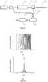
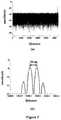
Figure 1 is a schematic diagram of the optical pulse compression reflectometer of the present invention.Figure 2 is a schematic diagram showing pulse compression processing with the optical pulse compression reflectometer of the present invention, where (a) shows the original pulse, and (b) shows the compressed pulse.Figure 3 is a schematicdiagram showing embodiment 1 of the modulation frequency pulse generating module of the optical pulse compression reflectometer of the present invention.Figure 4 is a schematic diagram showing a modulation frequency pulse generating module of the optical pulse compression reflectometer not being part of the present invention.Figure 5 is a schematic diagram of the pulse compression processing module of the optical pulse compression reflectometer of the present invention.Figure 6 shows experiment results for the optical pulse compression reflectometer of the present invention underembodiment 1 of the modulation frequency pulse generating module, where (a) shows a back scattered curve, (b) shows validation for the spatial resolution. (Conditions for the experiment:pulse width 2 µs, sweeping range 221 MHz, linewidth of the laser source 100 kHz, spatial resolution approximately 50 cm, and measurement range 5.4 km).Figure 7 shows experiment results for the optical pulse compression reflectometer offigure 4 of the modulation frequency pulse generating module, where (a) shows a back scattered curve, (b) shows validation for the spatial resolution. (Conditions for the experiment:pulse width 1 µs,sweeping range 1 GHz, linewidth of the laser source 100 kHz, spatial resolution approximately 100 cm, and measurement range 5.4 km).- In combination with drawings and embodiments hereunder provided, the present invention will be further expounded. The embodiments, providing detailed implementation means and procedures thereof under prerequisite of the technical solution of the present invention, are not meant to limit the scope of the present invention.
Figure 1 is a schematic diagram of the optical pulse compression reflectometer of the present invention, as is shown thereon, it comprises: a single wavelength continuousoptical source 1, anoptical splitter 2, a modulation frequencypulse generating module 3, an optical directional coupler 5, an optical fiber under test 6, an optical coupler 9, abalanced photodetecter 10, and a pulsecompression processing module 11;- The above components are inter-connected in the following manner:
A monochromatic continuous optical signal generated by the single wavelength continuousoptical source 1 is split by theoptical splitter 2; the modulation frequencypulse generating module 3 transforms one branch of the split optical signal to be a modulation frequency pulse to serve as a detection light 4, the first port of the optical directional coupler 5 receives the detection light 4 and outputs it via the second port thereof to the optical fiber under test 6, and at the mean time, the second port of the optical directional coupler 5 receives the back scattered light generated by the optical fiber under test 6 and outputs it out of the third port thereof. The second input port of the optical coupler 9 receives the back scattered light, while the other branch of the split optical signal split by theoptical splitter 2 is received in the first input port of the optical coupler 9 as a reference light 7; two outputs of the optical coupler 9 are received in thebalanced photodetecter 10 for coherent detection; the pulsecompression processing module 11 conducts pulse compression on the signal outputted from thebalanced photodetecter 10. - Take linear frequency modulation as an example, denote the linear frequency modulation pulse withs(t), and the compressed pulse signal withy(t), then,


Figure 2 shows a simulation diagram for the above process, that is, a diagram depicting the pulse compression of the pulse compression reflectometry system of the present invention, (a) showing the original pulse, and (b) showing the compressed pulse. Define the sweeping range asB=KT, then the pulse width shall be equal to the sweeping rangeB. Spatial resolutionZ could be defined as a distance between two smallest discernible events, and in time domain reflectometry, it is equal to a product of the width of a detection pulse with the light speed in the medium. As the present invention is concerned, the spatial resolution depends only on the sweeping rangeB,
- Measurement range of a system could be defined as the maximum distance for maintenance of a greater event signal power over the noise power, and in time domain reflectometry, it increases as the pulse width increases. As the spatial resolution of the pulse compression reflectometry system of the present invention depends only on the sweeping range B but not on the pulse width, the pulse compression reflectometry system of the present invention is capable of drastically increasing the measurement range by means of increasing the pulse width with the spatial resolution unchanged. Moreover, as can be seen from
Figure 2 , by employing pulse compression, energy originally evenly distributed is concentrated in a short time span, which increases the instantaneous power of the reflectometry signal at the event site, increases the signal/noise ratio, and further increases the measurement range. Figure 3 showsembodiment 1 of the modulation frequency pulse generating module of the optical pulse compression reflectometer of the present invention. As is shown thereon, the modulation frequency pulse generating module comprises: afirst polarization controller 12, a linear modulation frequency voltage controlledoscillator 13, awaveform generator 14, asingle sideband modulator 15, asecond polarization controller 16, a first erbium-doped fiber amplifier 17, a Mach-Zehnder electro-optic modulator 18, and a second erbium-dopedfiber amplifier 19. Components in theembodiment 1 of the modulation frequency pulse generating module are inter-connected in the following manner: thewaveform generator 14 generates a periodical sawtooth wave to drive the linear modulation frequency voltage controlledoscillator 13, and connects the output port of the linear modulation frequency voltage controlledoscillator 13 with the electric signal input port of thesingle sideband modulator 15; subsequently, one branch of optical signal split by theoptical splitter 2 is received in thesingle sideband modulator 15 en route of thefirst polarization controller 12; the output signal from thesingle sideband modulator 15 is received in the Mach-Zehnder electro-optic modulator 18 en route of thesecond polarization controller 16 and the first erbium-doped fiber amplifier 17; at the mean time, thewaveform generator 14 generates a pulse synchronous with the periodical sawtooth wave for reception in the electric signal input port of the Mach-Zehnder electro-optic modulator 18; the output optical signal from the Mach-Zehnder electro-optic modulator 18 is generated to be the detection light 4 via the second erbium-dopedfiber amplifier 19.Figure 4 shows a modulation frequency pulse generating module of an optical pulse compression reflectometer nor being part of the present invention. As is shown thereon, the modulation frequency pulse generating module comprises: awaveform generator 20, a linear modulation frequency voltage controlledoscillator 21, apolarization controller 22, asingle sideband modulator 23, and an erbium-dopedfiber amplifier 24. Components in theembodiment 2 of the modulation frequency pulse generating module are inter-connected in the following manner: thewaveform generator 20 generates two branches of optical signal, one is a periodical sawtooth wave, for reception in the electric signal input port of the linear modulation frequency voltage controlledoscillator 21; the other branch of optical signal is a periodical pulse signal, with a pulse width being equal to the period of the above periodical sawtooth wave, for reception in the enable input port of the linear modulation frequency voltage controlledoscillator 21. An output port of the linear modulation frequency voltage controlledoscillator 21 is connected with an electric signal input port of thesingle sideband modulator 23; subsequently, one branch of optical signal split by theoptical splitter 2 is received in thesingle sideband modulator 23 en route of thepolarization controller 22; the output optical signal from thesingle sideband modulator 23 is generated to be the detection light 4 via the erbium-dopedfiber amplifier 24.Figure 5 shows a schematic diagram of the pulse compression processing module of the optical pulse compression reflectometer of the present invention. As is shown thereon, the pulse compression processing module comprises adata collector 25, anorthogonal modulator 26 and amatch filter 27, which are successively connected. Thedata collector 25 collects an electric signal outputted by means of the coherent detection 8; saidorthogonal modulator 26 quadrature demodulates the collected signal, and saidmatch filter 27 match filters the quadrature demodulated signal.- The working principle of the present invention is as follows:
For a linear modulation frequency voltage controlled oscillator, being driven by a periodical sawtooth wave, outputs a continuous wave of linear frequency sweep. For a single sideband modulator, it merely modulates an input electric signal to either the upper sideband or the lower sideband, and therefore, the frequency of the output optical signal is in linear relation with the input electric signal. Inembodiment 1 of the modulation frequency pulse generating module, subsequent to reception of a continuous light of linear frequency sweep generated by the linear modulation frequency voltage controlled oscillator, the single sideband modulator will generate a continuous light of linear frequency sweep. Pass the continuous light of linear frequency sweep through the Mach-Zehnder electro-optic modulator, modulate up a pulse synchronous with the periodical sawtooth wave, and an optical pulse of linear frequency sweep will be obtained. In the example shown onfigure 4 of the modulation frequency pulse generating module, receive a pulse synchronous with the periodical sawtooth wave in an enable port of the linear modulation frequency voltage controlled oscillator, the linear modulation frequency voltage controlled oscillator will directly generate an electric pulse of linear frequency sweep. Hence, subsequent to reception of the electric pulse of linear frequency sweep generated by the linear modulation frequency voltage controlled oscillator, the single sideband modulator will directly generate an optical signal of linear frequency sweep. - Conduct optical interference on the back scattered light and the reference light of the optical fiber via the optical coupler, and subsequently conduct coherent detection via the balanced photodetecter to obtain electric field and frequency modulation information of the optical signal. Collect said information with the data collector, transform the obtained real signal to a complex signal, shift the center frequency of the signal downward to intermediate frequency or zero point, and then conduct match filtering, and the pulse compression will be realized with the signal/noise ratio of the back scattered signal drastically increased.


Claims (9)
- An optical pulse compression reflectometer, comprising: a single wavelength continuous optical source (1), an optical splitter (2), a modulation frequency pulse generating module (3), an optical directional coupler (5), an optical fiber under test (6), an optical coupler (9), a balanced photodetecter (10), and a pulse compression processing module (11);wherein
an output port of said single wavelength continuous optical source (1) is connected with an input port of said optical splitter (2), a first output port of the optical splitter (2) is connected with an input port of said modulation frequency pulse generating module (3), an output port the modulation frequency pulse generating module (3) is connected with a first port of the optical directional coupler (5),a second port of the optical directional coupler (5) is connected with said optical fiber under test (6), a third port of the optical directional coupler (5) is connected with a first input port of the optical coupler (9), and a second output port of the optical splitter (2) is directly connected with a second input port of the optical coupler (9);and two branches of output of the optical coupler (9) are received in said balanced photoelectric photodetecter (10), and an output port of the balanced photoelectric detector is connected with said pulse compression processing module (11);
wherein the optical directional coupler (5) is configured to output on the second port the light input on the first port, and to output on the third port the light input on the second port;
characterized in that the modulation frequency pulse generating module (3) comprises a first polarization controller (12), a linear modulation frequency voltage controlled oscillator (13), a waveform generator (14), a single sideband modulator (15), a second polarization controller (16), a first erbium-doped fiber amplifier (17), a Mach-Zehnder electro-optic modulator (18), and a second erbium-doped fiber amplifier (19); wherein a wave output port of said waveform generator (14) is connected with an input port of said linear modulation frequency voltage controlled oscillator (13), an output port of the linear modulation frequency voltage controlled oscillator (13) is connected with an electric signal input port of said single sideband modulator (15), the first output port of the optical splitter (2) is connected with an input port of said first polarization controller (12), an output port of the first polarization controller (12) is connected with an optical signal input port of the single sideband modulator, an output port of the single sideband modulator (15) is connected with an input port of said second polarization controller (16), an output port of the second polarization controller (16) is connected with an input port of said erbium-doped fiber amplifier (17), an output port of the erbium-doped fiber amplifier (17) is connected with an optical signal input port of said Mach-Zehnder electro-optic modulator (18), a pulse output port of the waveform generator (14) is connected with an electric signal input port of the Mach-Zehnder electro-optic modulator (18), and an output port of the Mach-Zehnder electro-optic modulator is connected with an input port of the optical directional coupler (5). - The optical pulse compression reflectometer of Claim 1, wherein the Mach-Zehnder electro-optic modulator (18) is an intensity modulator, a single sideband modulator, or an electro-absorption modulator.
- The optical pulse compression reflectometer of Claim 1, wherein the pulse compression processing module (11) comprises a data collector (25), and an orthogonal modulator (26) and a match filter (27), that are successively connected; wherein the data collector (25) is adapted to collect an electric signal outputted by the balanced photoelectric photodetecter (10), said orthogonal modulator (26) is adapted to quadrature demodulate the collected signal, and said match filter (27) is adapted to match filter the quadrature demodulated signal.
- The optical pulse compression reflectometer of Claim 3, wherein the data collector (20) is an analogue reception circuit, an analogue-digital transforming module, a data collection card, or an oscilloscope.
- The optical pulse compression reflectometer of Claim 2, wherein the pulse compression processing module (11) is an analogue signal processing circuit or a digital signal processor or comprises a computer software.
- The optical pulse compression reflectometer of Claim 1, wherein the single wavelength continuous optical source (1) is a semiconductor laser, an optical fiber laser, a gas laser, or a dye laser.
- The optical pulse compression reflectometer of Claim 1, wherein the optical coupler (9) is a 2×2 optical coupler.
- The optical pulse compression reflectometer of Claim 1, wherein the balanced photoelectric photodetecter (10) is a PIN diode or an APD.
- The optical pulse compression reflectometer of Claim 1, wherein the optical directional coupler (5) is an optical circulator or an optical coupler.
Applications Claiming Priority (2)
| Application Number | Priority Date | Filing Date | Title |
|---|---|---|---|
| CN201410211203.5ACN103984184B (en) | 2014-05-19 | 2014-05-19 | Light pulse compressive reflexes device |
| PCT/CN2014/081331WO2015176362A1 (en) | 2014-05-19 | 2014-07-01 | Light pulse compression reflector apparatus |
Publications (3)
| Publication Number | Publication Date |
|---|---|
| EP3098651A1 EP3098651A1 (en) | 2016-11-30 |
| EP3098651A4 EP3098651A4 (en) | 2017-04-12 |
| EP3098651B1true EP3098651B1 (en) | 2020-06-03 |
Family
ID=51276207
Family Applications (1)
| Application Number | Title | Priority Date | Filing Date |
|---|---|---|---|
| EP14870645.0AActiveEP3098651B1 (en) | 2014-05-19 | 2014-07-01 | Light pulse compression reflectometer |
Country Status (5)
| Country | Link |
|---|---|
| US (1) | US9689772B2 (en) |
| EP (1) | EP3098651B1 (en) |
| JP (1) | JP2016524715A (en) |
| CN (1) | CN103984184B (en) |
| WO (1) | WO2015176362A1 (en) |
Families Citing this family (19)
| Publication number | Priority date | Publication date | Assignee | Title |
|---|---|---|---|---|
| CN105067103B (en)* | 2015-08-31 | 2018-01-02 | 上海交通大学 | Vibration detection device and method based on optical frequency domain reflectometer |
| EP3386118B1 (en)* | 2016-01-05 | 2021-02-24 | Shanghai Jiaotong University | Frequency synthesis-based optical frequency domain reflectometry method and system |
| EP3312582B1 (en)* | 2016-10-20 | 2020-02-26 | Xieon Networks S.à r.l. | Otdr using an electro-absorption modulator for both pulse forming and pulse detection |
| CN106571880B (en)* | 2016-10-21 | 2020-06-02 | 北京无线电计量测试研究所 | System and method for measuring transmission parameters of terahertz device |
| US10222615B2 (en)* | 2017-05-26 | 2019-03-05 | Microsoft Technology Licensing, Llc | Optical waveguide with coherent light source |
| CN107402029B (en)* | 2017-08-08 | 2019-08-20 | 电子科技大学 | Method and system for improving measurement speed of distributed optical fiber sensing using orthogonal signals |
| CN107894587B (en)* | 2017-12-04 | 2021-07-06 | 电子科技大学 | A pulsed laser homodyne coherent detection device based on optical phase locking |
| JP7061364B2 (en)* | 2018-06-11 | 2022-04-28 | 国立大学法人東京農工大学 | Distance measuring device and distance measuring method |
| EP3703283A1 (en)* | 2019-02-27 | 2020-09-02 | Fundació Institut de Ciències Fotòniques | Generation of optical pulses with controlled distributions of quadrature values |
| CN110285333B (en)* | 2019-07-12 | 2024-12-17 | 上海交通大学 | Oil gas pipeline leakage monitoring method of oil gas pipeline leakage monitoring system based on optical fiber |
| CN110635841B (en)* | 2019-08-16 | 2022-07-15 | 深圳市矽赫科技有限公司 | Method and device for improving echo signal of chaotic optical time domain reflectometer |
| US11494541B2 (en)* | 2020-01-16 | 2022-11-08 | Lightmatter, Inc. | Pin sharing for photonic processors |
| CN113517922B (en) | 2020-04-09 | 2022-09-02 | 华为技术有限公司 | Signal detection method and optical time domain reflectometer |
| KR102330484B1 (en)* | 2021-04-29 | 2021-11-24 | 주식회사 에니트 | Distributed acoustic sensing with improved extinction ratio |
| CN113639650B (en)* | 2021-08-10 | 2023-12-12 | 安徽大学 | Optical frequency domain reflectometer type sensing demodulation method based on phase accumulation measurement method |
| EP4155708A1 (en) | 2021-09-24 | 2023-03-29 | Viavi Solutions Inc. | Optical time-domain reflectometer (otdr) including channel checker |
| US11942986B2 (en)* | 2021-09-24 | 2024-03-26 | Viavi Solutions Inc. | Optical time-domain reflectometer (OTDR) including channel checker |
| CN115235367B (en)* | 2022-07-26 | 2023-04-25 | 北京理工大学 | High-precision double-frequency optical frequency domain reflectometer with large strain measurement range |
| CN115603822B (en)* | 2022-09-30 | 2025-04-08 | 贵州大学 | Time Domain Integration System |
Citations (1)
| Publication number | Priority date | Publication date | Assignee | Title |
|---|---|---|---|---|
| CN103401606A (en)* | 2013-07-22 | 2013-11-20 | 国家电网公司 | Coherent optical time-domain reflectometer based on detection frequency coding |
Family Cites Families (17)
| Publication number | Priority date | Publication date | Assignee | Title |
|---|---|---|---|---|
| US5000568A (en)* | 1986-11-26 | 1991-03-19 | Hewlett-Packard Company | Spread spectrum optical time domain reflectometer |
| US5062703A (en)* | 1988-01-21 | 1991-11-05 | Hewlett-Packard Company | Method and apparatus for measuring the length of, or distances to discontinuities in, an optical transmission medium |
| GB8929258D0 (en)* | 1989-12-28 | 1990-02-28 | Secr Defence | Optical time domain reflectometer |
| US5353110A (en)* | 1991-07-12 | 1994-10-04 | Tektronix, Inc. | Method and apparatus for carrying out optical time domain reflectometry using weighing techniques |
| US5365531A (en)* | 1992-11-24 | 1994-11-15 | Hewlett-Packard Company | Apparatus and method for initializing an optical-fiber laser for mode locking |
| JP3284751B2 (en)* | 1994-05-27 | 2002-05-20 | 日本電信電話株式会社 | Optical pulse compression device |
| JP2001521181A (en)* | 1997-10-23 | 2001-11-06 | コーニング インコーポレイテッド | Nonlinear optical loop mirror using adiabatic pulse compression |
| AU2002344444A1 (en)* | 2002-11-01 | 2004-05-25 | Kinzo Kishida | Distributed optical fiber sensor system |
| CN1256611C (en)* | 2004-07-16 | 2006-05-17 | 中国科学院上海光学精密机械研究所 | Optical Pulse Arbitrary Time Shaping Device |
| CN100504566C (en)* | 2006-04-21 | 2009-06-24 | 中国科学院物理研究所 | A chirped pulse compression method and device |
| JP2008122108A (en)* | 2006-11-08 | 2008-05-29 | Anritsu Corp | Optical pulse tester |
| JP4933981B2 (en)* | 2007-08-14 | 2012-05-16 | 横河電機株式会社 | Optical fiber characteristic measuring device |
| PT2284514E (en)* | 2008-06-02 | 2016-01-13 | Sumitomo Electric Industries | Beam path monitoring device, and beam path monitoring system |
| CN101639602A (en)* | 2008-07-29 | 2010-02-03 | 聊城大学 | Novel high-speed optical pulse compression system |
| JP2011053146A (en)* | 2009-09-03 | 2011-03-17 | Neubrex Co Ltd | Detection cable, and monitoring system including the same |
| CN102322880B (en)* | 2011-08-18 | 2013-06-05 | 天津大学 | Polarization sensitive distributive optical frequency domain reflection disturbance sensor and demodulation method |
| CN102645268A (en)* | 2012-04-26 | 2012-08-22 | 中国科学院上海光学精密机械研究所 | Optical frequency division multiplexing phase-sensitive optical time domain reflectometer |
- 2014
- 2014-05-19CNCN201410211203.5Apatent/CN103984184B/enactiveActive
- 2014-07-01USUS14/443,916patent/US9689772B2/enactiveActive
- 2014-07-01EPEP14870645.0Apatent/EP3098651B1/enactiveActive
- 2014-07-01JPJP2016520269Apatent/JP2016524715A/enactivePending
- 2014-07-01WOPCT/CN2014/081331patent/WO2015176362A1/ennot_activeCeased
Patent Citations (1)
| Publication number | Priority date | Publication date | Assignee | Title |
|---|---|---|---|---|
| CN103401606A (en)* | 2013-07-22 | 2013-11-20 | 国家电网公司 | Coherent optical time-domain reflectometer based on detection frequency coding |
Non-Patent Citations (2)
| Title |
|---|
| HIROYUKI IIDA ET AL: "High-Sensitivity Coherent Optical Time Domain Reflectometry Employing Frequency-Division Multiplexing", JOURNAL OF LIGHTWAVE TECHNOLOGY, IEEE, USA, vol. 30, no. 8, 1 April 2012 (2012-04-01), pages 1121 - 1126, XP011430146, ISSN: 0733-8724, DOI: 10.1109/JLT.2011.2170960* |
| IIDA HIROYUKI ET AL: "Ultra high dynamic range coherent optical time domain reflectometry employing frequency division multiplexing", 21ST INTERNATIONAL CONFERENCE ON OPTICAL FIBER SENSORS, SPIE, 1000 20TH ST. BELLINGHAM WA 98225-6705 USA, vol. 7753, no. 1, 15 May 2011 (2011-05-15), pages 1 - 4, XP060011620, DOI: 10.1117/12.885586* |
Also Published As
| Publication number | Publication date |
|---|---|
| EP3098651A1 (en) | 2016-11-30 |
| EP3098651A4 (en) | 2017-04-12 |
| WO2015176362A1 (en) | 2015-11-26 |
| JP2016524715A (en) | 2016-08-18 |
| US20160245719A1 (en) | 2016-08-25 |
| CN103984184B (en) | 2016-08-24 |
| CN103984184A (en) | 2014-08-13 |
| US9689772B2 (en) | 2017-06-27 |
Similar Documents
| Publication | Publication Date | Title |
|---|---|---|
| EP3098651B1 (en) | Light pulse compression reflectometer | |
| US10564012B2 (en) | Method of improving measurement speed of distributed optical fiber sensor by adopting orthogonal signals and system thereof | |
| AU2020102296A4 (en) | A distributed optical fiber sensing system based on heterodyne detection technology | |
| US10066973B2 (en) | Brillouin scattering measurement method and brillouin scattering measurement system | |
| EP3889644A1 (en) | Optical measurement device and measurement method | |
| JP6698164B2 (en) | Optical frequency domain reflection method and system based on frequency synthesis | |
| CN103940361B (en) | A kind of fiber grating low frequency strain sensing demodulating system | |
| EP1865289A2 (en) | Method for measuring the Brillouin shift distribution along optical fiber based on the optical demodulation of the signals, and relevant apparatus | |
| CN107894276A (en) | The distributed optical fiber vibration sensing device and implementation method of a kind of high frequency sound | |
| CN103163530B (en) | Phase modulation direct detection laser Doppler velometer and velocity measuring method thereof | |
| CN114424029B (en) | Method and device for reconstructing backscattered electromagnetic vector waves | |
| CN102645268A (en) | Optical frequency division multiplexing phase-sensitive optical time domain reflectometer | |
| CN104568119A (en) | Optical fiber vibration sensing system of single light source pulse and sensing method thereof | |
| KR101889351B1 (en) | Spatially-selective brillouin distributed optical fiber sensor with increased effective sensing points and sensing method using brillouin scattering | |
| CN108873007B (en) | A Frequency Modulated Continuous Wave Laser Distance Measuring Device Suppressing Vibration Effect | |
| CN108344558B (en) | Optical fiber optical time domain reflectometer detection system and method based on linear frequency modulation signal | |
| KR101326859B1 (en) | Optical fiber sensor system based brillouin scattering | |
| CN104764592A (en) | Measurement method of chirp parameters of electro-optic intensity modulator | |
| CN103900623A (en) | Optical time domain reflectometer based on double acoustic-optical modulators and common-mode rejection method of optical time domain reflectometer | |
| CN101625279B (en) | Device for positioning optical fiber breakpoints and method for confirming breakpoint positions | |
| CN113810098B (en) | An Optical Time Domain Reflectometer Based on Double Sideband Chirped Pulse Modulation | |
| CN109724529A (en) | Large dynamic range Brillouin fast measurement system based on multi-slope assistance | |
| CN108845333A (en) | A kind of FM-CW laser ranging method inhibiting dither effect | |
| CN118794525B (en) | Measuring method and device based on forward light and backward scattering | |
| CN106908803B (en) | Ultra wide band scalariform FM/CW laser velocimeter system based on double parallel MZM |
Legal Events
| Date | Code | Title | Description |
|---|---|---|---|
| PUAI | Public reference made under article 153(3) epc to a published international application that has entered the european phase | Free format text:ORIGINAL CODE: 0009012 | |
| 17P | Request for examination filed | Effective date:20160112 | |
| AK | Designated contracting states | Kind code of ref document:A1 Designated state(s):AL AT BE BG CH CY CZ DE DK EE ES FI FR GB GR HR HU IE IS IT LI LT LU LV MC MK MT NL NO PL PT RO RS SE SI SK SM TR | |
| AX | Request for extension of the european patent | Extension state:BA ME | |
| A4 | Supplementary search report drawn up and despatched | Effective date:20170314 | |
| RIC1 | Information provided on ipc code assigned before grant | Ipc:G02B 6/42 20060101ALI20170308BHEP Ipc:G02F 1/35 20060101AFI20170308BHEP Ipc:G01M 11/00 20060101ALI20170308BHEP | |
| DAX | Request for extension of the european patent (deleted) | ||
| STAA | Information on the status of an ep patent application or granted ep patent | Free format text:STATUS: EXAMINATION IS IN PROGRESS | |
| 17Q | First examination report despatched | Effective date:20180511 | |
| GRAP | Despatch of communication of intention to grant a patent | Free format text:ORIGINAL CODE: EPIDOSNIGR1 | |
| STAA | Information on the status of an ep patent application or granted ep patent | Free format text:STATUS: GRANT OF PATENT IS INTENDED | |
| INTG | Intention to grant announced | Effective date:20200219 | |
| GRAS | Grant fee paid | Free format text:ORIGINAL CODE: EPIDOSNIGR3 | |
| GRAA | (expected) grant | Free format text:ORIGINAL CODE: 0009210 | |
| STAA | Information on the status of an ep patent application or granted ep patent | Free format text:STATUS: THE PATENT HAS BEEN GRANTED | |
| AK | Designated contracting states | Kind code of ref document:B1 Designated state(s):AL AT BE BG CH CY CZ DE DK EE ES FI FR GB GR HR HU IE IS IT LI LT LU LV MC MK MT NL NO PL PT RO RS SE SI SK SM TR | |
| REG | Reference to a national code | Ref country code:GB Ref legal event code:FG4D | |
| REG | Reference to a national code | Ref country code:CH Ref legal event code:EP Ref country code:AT Ref legal event code:REF Ref document number:1277615 Country of ref document:AT Kind code of ref document:T Effective date:20200615 | |
| REG | Reference to a national code | Ref country code:DE Ref legal event code:R096 Ref document number:602014066355 Country of ref document:DE | |
| PGFP | Annual fee paid to national office [announced via postgrant information from national office to epo] | Ref country code:NL Payment date:20200723 Year of fee payment:7 | |
| REG | Reference to a national code | Ref country code:LT Ref legal event code:MG4D | |
| PG25 | Lapsed in a contracting state [announced via postgrant information from national office to epo] | Ref country code:GR Free format text:LAPSE BECAUSE OF FAILURE TO SUBMIT A TRANSLATION OF THE DESCRIPTION OR TO PAY THE FEE WITHIN THE PRESCRIBED TIME-LIMIT Effective date:20200904 Ref country code:NO Free format text:LAPSE BECAUSE OF FAILURE TO SUBMIT A TRANSLATION OF THE DESCRIPTION OR TO PAY THE FEE WITHIN THE PRESCRIBED TIME-LIMIT Effective date:20200903 Ref country code:FI Free format text:LAPSE BECAUSE OF FAILURE TO SUBMIT A TRANSLATION OF THE DESCRIPTION OR TO PAY THE FEE WITHIN THE PRESCRIBED TIME-LIMIT Effective date:20200603 Ref country code:SE Free format text:LAPSE BECAUSE OF FAILURE TO SUBMIT A TRANSLATION OF THE DESCRIPTION OR TO PAY THE FEE WITHIN THE PRESCRIBED TIME-LIMIT Effective date:20200603 Ref country code:LT Free format text:LAPSE BECAUSE OF FAILURE TO SUBMIT A TRANSLATION OF THE DESCRIPTION OR TO PAY THE FEE WITHIN THE PRESCRIBED TIME-LIMIT Effective date:20200603 | |
| REG | Reference to a national code | Ref country code:NL Ref legal event code:MP Effective date:20200603 | |
| PG25 | Lapsed in a contracting state [announced via postgrant information from national office to epo] | Ref country code:BG Free format text:LAPSE BECAUSE OF FAILURE TO SUBMIT A TRANSLATION OF THE DESCRIPTION OR TO PAY THE FEE WITHIN THE PRESCRIBED TIME-LIMIT Effective date:20200903 Ref country code:RS Free format text:LAPSE BECAUSE OF FAILURE TO SUBMIT A TRANSLATION OF THE DESCRIPTION OR TO PAY THE FEE WITHIN THE PRESCRIBED TIME-LIMIT Effective date:20200603 Ref country code:LV Free format text:LAPSE BECAUSE OF FAILURE TO SUBMIT A TRANSLATION OF THE DESCRIPTION OR TO PAY THE FEE WITHIN THE PRESCRIBED TIME-LIMIT Effective date:20200603 Ref country code:HR Free format text:LAPSE BECAUSE OF FAILURE TO SUBMIT A TRANSLATION OF THE DESCRIPTION OR TO PAY THE FEE WITHIN THE PRESCRIBED TIME-LIMIT Effective date:20200603 | |
| REG | Reference to a national code | Ref country code:AT Ref legal event code:MK05 Ref document number:1277615 Country of ref document:AT Kind code of ref document:T Effective date:20200603 | |
| PG25 | Lapsed in a contracting state [announced via postgrant information from national office to epo] | Ref country code:AL Free format text:LAPSE BECAUSE OF FAILURE TO SUBMIT A TRANSLATION OF THE DESCRIPTION OR TO PAY THE FEE WITHIN THE PRESCRIBED TIME-LIMIT Effective date:20200603 Ref country code:NL Free format text:LAPSE BECAUSE OF FAILURE TO SUBMIT A TRANSLATION OF THE DESCRIPTION OR TO PAY THE FEE WITHIN THE PRESCRIBED TIME-LIMIT Effective date:20200603 | |
| PG25 | Lapsed in a contracting state [announced via postgrant information from national office to epo] | Ref country code:AT Free format text:LAPSE BECAUSE OF FAILURE TO SUBMIT A TRANSLATION OF THE DESCRIPTION OR TO PAY THE FEE WITHIN THE PRESCRIBED TIME-LIMIT Effective date:20200603 Ref country code:SM Free format text:LAPSE BECAUSE OF FAILURE TO SUBMIT A TRANSLATION OF THE DESCRIPTION OR TO PAY THE FEE WITHIN THE PRESCRIBED TIME-LIMIT Effective date:20200603 Ref country code:EE Free format text:LAPSE BECAUSE OF FAILURE TO SUBMIT A TRANSLATION OF THE DESCRIPTION OR TO PAY THE FEE WITHIN THE PRESCRIBED TIME-LIMIT Effective date:20200603 Ref country code:PT Free format text:LAPSE BECAUSE OF FAILURE TO SUBMIT A TRANSLATION OF THE DESCRIPTION OR TO PAY THE FEE WITHIN THE PRESCRIBED TIME-LIMIT Effective date:20201006 Ref country code:CZ Free format text:LAPSE BECAUSE OF FAILURE TO SUBMIT A TRANSLATION OF THE DESCRIPTION OR TO PAY THE FEE WITHIN THE PRESCRIBED TIME-LIMIT Effective date:20200603 Ref country code:RO Free format text:LAPSE BECAUSE OF FAILURE TO SUBMIT A TRANSLATION OF THE DESCRIPTION OR TO PAY THE FEE WITHIN THE PRESCRIBED TIME-LIMIT Effective date:20200603 Ref country code:ES Free format text:LAPSE BECAUSE OF FAILURE TO SUBMIT A TRANSLATION OF THE DESCRIPTION OR TO PAY THE FEE WITHIN THE PRESCRIBED TIME-LIMIT Effective date:20200603 | |
| PG25 | Lapsed in a contracting state [announced via postgrant information from national office to epo] | Ref country code:PL Free format text:LAPSE BECAUSE OF FAILURE TO SUBMIT A TRANSLATION OF THE DESCRIPTION OR TO PAY THE FEE WITHIN THE PRESCRIBED TIME-LIMIT Effective date:20200603 Ref country code:SK Free format text:LAPSE BECAUSE OF FAILURE TO SUBMIT A TRANSLATION OF THE DESCRIPTION OR TO PAY THE FEE WITHIN THE PRESCRIBED TIME-LIMIT Effective date:20200603 Ref country code:IS Free format text:LAPSE BECAUSE OF FAILURE TO SUBMIT A TRANSLATION OF THE DESCRIPTION OR TO PAY THE FEE WITHIN THE PRESCRIBED TIME-LIMIT Effective date:20201003 | |
| REG | Reference to a national code | Ref country code:CH Ref legal event code:PL | |
| REG | Reference to a national code | Ref country code:DE Ref legal event code:R097 Ref document number:602014066355 Country of ref document:DE | |
| PG25 | Lapsed in a contracting state [announced via postgrant information from national office to epo] | Ref country code:MC Free format text:LAPSE BECAUSE OF FAILURE TO SUBMIT A TRANSLATION OF THE DESCRIPTION OR TO PAY THE FEE WITHIN THE PRESCRIBED TIME-LIMIT Effective date:20200603 | |
| PLBE | No opposition filed within time limit | Free format text:ORIGINAL CODE: 0009261 | |
| STAA | Information on the status of an ep patent application or granted ep patent | Free format text:STATUS: NO OPPOSITION FILED WITHIN TIME LIMIT | |
| PG25 | Lapsed in a contracting state [announced via postgrant information from national office to epo] | Ref country code:LU Free format text:LAPSE BECAUSE OF NON-PAYMENT OF DUE FEES Effective date:20200701 Ref country code:LI Free format text:LAPSE BECAUSE OF NON-PAYMENT OF DUE FEES Effective date:20200731 Ref country code:DK Free format text:LAPSE BECAUSE OF FAILURE TO SUBMIT A TRANSLATION OF THE DESCRIPTION OR TO PAY THE FEE WITHIN THE PRESCRIBED TIME-LIMIT Effective date:20200603 Ref country code:CH Free format text:LAPSE BECAUSE OF NON-PAYMENT OF DUE FEES Effective date:20200731 Ref country code:IE Free format text:LAPSE BECAUSE OF NON-PAYMENT OF DUE FEES Effective date:20200701 | |
| 26N | No opposition filed | Effective date:20210304 | |
| GBPC | Gb: european patent ceased through non-payment of renewal fee | Effective date:20200903 | |
| PG25 | Lapsed in a contracting state [announced via postgrant information from national office to epo] | Ref country code:SI Free format text:LAPSE BECAUSE OF FAILURE TO SUBMIT A TRANSLATION OF THE DESCRIPTION OR TO PAY THE FEE WITHIN THE PRESCRIBED TIME-LIMIT Effective date:20200603 | |
| PG25 | Lapsed in a contracting state [announced via postgrant information from national office to epo] | Ref country code:GB Free format text:LAPSE BECAUSE OF NON-PAYMENT OF DUE FEES Effective date:20200903 | |
| PG25 | Lapsed in a contracting state [announced via postgrant information from national office to epo] | Ref country code:TR Free format text:LAPSE BECAUSE OF FAILURE TO SUBMIT A TRANSLATION OF THE DESCRIPTION OR TO PAY THE FEE WITHIN THE PRESCRIBED TIME-LIMIT Effective date:20200603 Ref country code:MT Free format text:LAPSE BECAUSE OF FAILURE TO SUBMIT A TRANSLATION OF THE DESCRIPTION OR TO PAY THE FEE WITHIN THE PRESCRIBED TIME-LIMIT Effective date:20200603 Ref country code:CY Free format text:LAPSE BECAUSE OF FAILURE TO SUBMIT A TRANSLATION OF THE DESCRIPTION OR TO PAY THE FEE WITHIN THE PRESCRIBED TIME-LIMIT Effective date:20200603 | |
| PG25 | Lapsed in a contracting state [announced via postgrant information from national office to epo] | Ref country code:MK Free format text:LAPSE BECAUSE OF FAILURE TO SUBMIT A TRANSLATION OF THE DESCRIPTION OR TO PAY THE FEE WITHIN THE PRESCRIBED TIME-LIMIT Effective date:20200603 | |
| PGFP | Annual fee paid to national office [announced via postgrant information from national office to epo] | Ref country code:FR Payment date:20240619 Year of fee payment:11 | |
| PGFP | Annual fee paid to national office [announced via postgrant information from national office to epo] | Ref country code:DE Payment date:20240712 Year of fee payment:11 | |
| PGFP | Annual fee paid to national office [announced via postgrant information from national office to epo] | Ref country code:BE Payment date:20240726 Year of fee payment:11 | |
| PGFP | Annual fee paid to national office [announced via postgrant information from national office to epo] | Ref country code:IT Payment date:20240708 Year of fee payment:11 |