EP3098196B1 - Positioning method in microprocessing process of bulk silicon - Google Patents
Positioning method in microprocessing process of bulk siliconDownload PDFInfo
- Publication number
- EP3098196B1 EP3098196B1EP15860320.9AEP15860320AEP3098196B1EP 3098196 B1EP3098196 B1EP 3098196B1EP 15860320 AEP15860320 AEP 15860320AEP 3098196 B1EP3098196 B1EP 3098196B1
- Authority
- EP
- European Patent Office
- Prior art keywords
- lithography machine
- alignment mark
- substrate
- double
- sided
- Prior art date
- Legal status (The legal status is an assumption and is not a legal conclusion. Google has not performed a legal analysis and makes no representation as to the accuracy of the status listed.)
- Active
Links
- 238000000034methodMethods0.000titleclaimsdescription52
- 229910052710siliconInorganic materials0.000titleclaimsdescription41
- 239000010703siliconSubstances0.000titleclaimsdescription41
- 238000001459lithographyMethods0.000claimsdescription131
- 239000000758substrateSubstances0.000claimsdescription79
- XUIMIQQOPSSXEZ-UHFFFAOYSA-NSiliconChemical compound[Si]XUIMIQQOPSSXEZ-UHFFFAOYSA-N0.000claimsdescription41
- 238000005459micromachiningMethods0.000claimsdescription22
- 238000005516engineering processMethods0.000claimsdescription4
- 238000005530etchingMethods0.000claimsdescription2
- 235000012431wafersNutrition0.000claims1
- 239000000463materialSubstances0.000description2
- 230000001133accelerationEffects0.000description1
- 238000001312dry etchingMethods0.000description1
- 230000000694effectsEffects0.000description1
- 238000004519manufacturing processMethods0.000description1
- 229910021421monocrystalline siliconInorganic materials0.000description1
- 230000003287optical effectEffects0.000description1
- 239000004065semiconductorSubstances0.000description1
- 238000001039wet etchingMethods0.000description1
Images

Classifications
- B—PERFORMING OPERATIONS; TRANSPORTING
- B81—MICROSTRUCTURAL TECHNOLOGY
- B81C—PROCESSES OR APPARATUS SPECIALLY ADAPTED FOR THE MANUFACTURE OR TREATMENT OF MICROSTRUCTURAL DEVICES OR SYSTEMS
- B81C3/00—Assembling of devices or systems from individually processed components
- B81C3/002—Aligning microparts
- B81C3/004—Active alignment, i.e. moving the elements in response to the detected position of the elements using internal or external actuators
- B—PERFORMING OPERATIONS; TRANSPORTING
- B81—MICROSTRUCTURAL TECHNOLOGY
- B81C—PROCESSES OR APPARATUS SPECIALLY ADAPTED FOR THE MANUFACTURE OR TREATMENT OF MICROSTRUCTURAL DEVICES OR SYSTEMS
- B81C1/00—Manufacture or treatment of devices or systems in or on a substrate
- B—PERFORMING OPERATIONS; TRANSPORTING
- B81—MICROSTRUCTURAL TECHNOLOGY
- B81C—PROCESSES OR APPARATUS SPECIALLY ADAPTED FOR THE MANUFACTURE OR TREATMENT OF MICROSTRUCTURAL DEVICES OR SYSTEMS
- B81C1/00—Manufacture or treatment of devices or systems in or on a substrate
- B81C1/00436—Shaping materials, i.e. techniques for structuring the substrate or the layers on the substrate
- B81C1/00555—Achieving a desired geometry, i.e. controlling etch rates, anisotropy or selectivity
- B81C1/00603—Aligning features and geometries on both sides of a substrate, e.g. when double side etching
- B—PERFORMING OPERATIONS; TRANSPORTING
- B81—MICROSTRUCTURAL TECHNOLOGY
- B81C—PROCESSES OR APPARATUS SPECIALLY ADAPTED FOR THE MANUFACTURE OR TREATMENT OF MICROSTRUCTURAL DEVICES OR SYSTEMS
- B81C3/00—Assembling of devices or systems from individually processed components
- G—PHYSICS
- G03—PHOTOGRAPHY; CINEMATOGRAPHY; ANALOGOUS TECHNIQUES USING WAVES OTHER THAN OPTICAL WAVES; ELECTROGRAPHY; HOLOGRAPHY
- G03F—PHOTOMECHANICAL PRODUCTION OF TEXTURED OR PATTERNED SURFACES, e.g. FOR PRINTING, FOR PROCESSING OF SEMICONDUCTOR DEVICES; MATERIALS THEREFOR; ORIGINALS THEREFOR; APPARATUS SPECIALLY ADAPTED THEREFOR
- G03F9/00—Registration or positioning of originals, masks, frames, photographic sheets or textured or patterned surfaces, e.g. automatically
- H—ELECTRICITY
- H01—ELECTRIC ELEMENTS
- H01L—SEMICONDUCTOR DEVICES NOT COVERED BY CLASS H10
- H01L21/00—Processes or apparatus adapted for the manufacture or treatment of semiconductor or solid state devices or of parts thereof
- H01L21/67—Apparatus specially adapted for handling semiconductor or electric solid state devices during manufacture or treatment thereof; Apparatus specially adapted for handling wafers during manufacture or treatment of semiconductor or electric solid state devices or components ; Apparatus not specifically provided for elsewhere
- H01L21/68—Apparatus specially adapted for handling semiconductor or electric solid state devices during manufacture or treatment thereof; Apparatus specially adapted for handling wafers during manufacture or treatment of semiconductor or electric solid state devices or components ; Apparatus not specifically provided for elsewhere for positioning, orientation or alignment
- B—PERFORMING OPERATIONS; TRANSPORTING
- B81—MICROSTRUCTURAL TECHNOLOGY
- B81C—PROCESSES OR APPARATUS SPECIALLY ADAPTED FOR THE MANUFACTURE OR TREATMENT OF MICROSTRUCTURAL DEVICES OR SYSTEMS
- B81C2203/00—Forming microstructural systems
- B81C2203/05—Aligning components to be assembled
- B81C2203/051—Active alignment, e.g. using internal or external actuators, magnets, sensors, marks or marks detectors
Definitions
- the present inventionrelates to a technical field of semiconductors, and more particularly relates to a positioning method in micromachining process for a bulk silicon.
- MEMS micromachining technologyincludes a micromachining process for a bulk silicon and a surface micromachining technology.
- a commonly used micromachining process for a bulk siliconis: first fabricating patterns (such as a deep channel) on one silicon wafer, and then bonding the silicon wafer to another one silicon wafer, performing a grinding to the bonded silicon wafer, and fabricating patterns on a surface of the bonded silicon wafer.
- the micromachining process for a bulk siliconcan manufacture a monocrystalline silicon structure having a greater thickness, and is extensively applied to fields such as an acceleration sensor, a gyroscope, and a microscope.
- the double-sided lithography machineIn order to guarantee an alignment between the patterns on surfaces of the upper silicon wafer and the lower silicon wafer, before bonding, it requires a double-sided lithography machine to fabricate pattern on the lower surface of the first silicon wafer, the pattern is aligned to the pattern on the upper surface. After being bonded to the second silicon wafer, it also requires the double-sided lithography machine to fabricate pattern on the upper surface on the second silicon wafer, the pattern is aligned to the pattern on the lower surface of the silicon wafer, such that the pattern on the upper surface of the second silicon wafer is indirectly aligned to the pattern on the upper surface of the first silicon wafer.
- the double-sided lithography machineadopts a proximity exposure and a contact exposure, i.e.
- the alignment accuracy of the methodis relative lower, the alignment accuracy generally is 2-3 micrometers. Because the double-sided lithography machine is adopted twice, the alignment accuracy between the patterns on the upper surface and the lower surface generally is 4-6 micrometers, the alignment accuracy is poor.
- Document CN 103558740 Adiscloses a prior art positioning method comprising fabricating a first pattern and a stepper lithography machine alignment mark configured to position the first pattern; and fabricating a second alignment mark corresponding to the first alignment mark on a second surface of the substrate.
- a positioning method in micromachining process for a bulk siliconincludes: fabricating a first pattern, a stepper lithography machine alignment mark configured to position the first pattern, and a first alignment mark for a double-sided lithography machine configured to position the stepper lithography machine alignment mark on a first surface of a first substrate; fabricating a second alignment mark for a double-sided lithography machine corresponding to the first alignment mark for a double-sided lithography machine on a second surface of the first substrate opposite to the first surface; bonding a second substrate on the first surface of the first substrate; performing a grinding process to a first surface of the second substrate; fabricating a third alignment mark for a double-sided lithography machine corresponding to the second alignment mark for a double-sided lithography machine on the first surface of the second substrate; and finding a position corresponding to the stepper lithography machine alignment mark by the third alignment mark for a double-sided lithography machine on the first surface of the second substrate.
- a method combining the double-sided lithography to the stepper lithographyis adopted, the stepper lithography machine alignment mark for the stepper lithography machine on the first substrate is found by the double-sided lithography machine, and then the second substrate is directly aligned by the stepper lithography machine.
- the alignment accuracy of the stepper lithography machineis equivalent to an alignment accuracy of the patterns on surfaces of the upper/lower substrate, such that the alignment accuracy of the micromachining process for a bulk silicon is improved greatly.
- the stepper lithography machineis an integrated optic-mechanical-electron system which gathers precision optics, precision mechanics and automatic controls, the alignment accuracy can be less than 0.5 micrometers, therefore, the alignment accuracy of the micromachining process for a bulk silicon can be less than 0.5 micrometers.
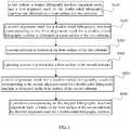
- FIG. 1is a flow chart of a position method in micromachining process for a bulk silicon according to an embodiment.
- a positioning method in micromachining process for a bulk siliconincludes steps as follows:
- the advantageous effect of the determination of the stepper lithography machine alignment mark 200is that, the position of the first pattern 100 can be determined by the stepper lithography machine alignment mark 200 again in the following steps, such that a second pattern 700 corresponding to the position of the first pattern 100 can be fabricated.
- a method combining the double-sided lithography to the stepper lithographyis adopted, the position of the stepper lithography machine alignment mark 200 of the stepper lithography machine on the first substrate is found by the double-sided lithography machine, and then an alignment is performed to the second substrate 20 directly by the stepper lithography machine.
- the alignment accuracy of the stepper lithography machineis equivalent to an alignment accuracy of the patterns (the first pattern 100 and the second pattern 700) on surfaces of the upper/lower substrate (the first substrate 10 and the second substrate 20), such that the alignment accuracy of the micromachining process for a bulk silicon is improved greatly. It is specifically illustrated with reference to the following embodiments.
- FIG. 5is a flow chart of a position method in micromachining process for a bulk silicon according to another embodiment.
- a positioning method in micromachining process for a bulk siliconincludes steps as follows:
- a method combining the double-sided lithography to the stepper lithographyis adopted, the stepper lithography machine alignment mark of the stepper lithography machine on the first substrate is found by the double-sided lithography machine, and then the second substrate is directly aligned by the stepper lithography machine.
- the alignment accuracy of the stepper lithography machineis equivalent to an alignment accuracy of the patterns on surfaces of the upper/lower substrate, such that the alignment accuracy of the micromachining process for a bulk silicon is improved greatly.
- the stepper lithography machineis an integrated optic-mechanical-electron system which gathers precision optics, precision mechanics and automatic controls, the alignment accuracy can be less than 0.5 micrometers, therefore, the alignment accuracy of the micromachining process for a bulk silicon can be less than 0.5 micrometers.
Landscapes
- Engineering & Computer Science (AREA)
- Microelectronics & Electronic Packaging (AREA)
- Physics & Mathematics (AREA)
- Manufacturing & Machinery (AREA)
- General Physics & Mathematics (AREA)
- Condensed Matter Physics & Semiconductors (AREA)
- Computer Hardware Design (AREA)
- Power Engineering (AREA)
- Geometry (AREA)
- Exposure And Positioning Against Photoresist Photosensitive Materials (AREA)
- Micromachines (AREA)
- Exposure Of Semiconductors, Excluding Electron Or Ion Beam Exposure (AREA)
Description
- The present invention relates to a technical field of semiconductors, and more particularly relates to a positioning method in micromachining process for a bulk silicon.
- MEMS micromachining technology includes a micromachining process for a bulk silicon and a surface micromachining technology. A commonly used micromachining process for a bulk silicon is: first fabricating patterns (such as a deep channel) on one silicon wafer, and then bonding the silicon wafer to another one silicon wafer, performing a grinding to the bonded silicon wafer, and fabricating patterns on a surface of the bonded silicon wafer. The micromachining process for a bulk silicon can manufacture a monocrystalline silicon structure having a greater thickness, and is extensively applied to fields such as an acceleration sensor, a gyroscope, and a microscope. In order to guarantee an alignment between the patterns on surfaces of the upper silicon wafer and the lower silicon wafer, before bonding, it requires a double-sided lithography machine to fabricate pattern on the lower surface of the first silicon wafer, the pattern is aligned to the pattern on the upper surface. After being bonded to the second silicon wafer, it also requires the double-sided lithography machine to fabricate pattern on the upper surface on the second silicon wafer, the pattern is aligned to the pattern on the lower surface of the silicon wafer, such that the pattern on the upper surface of the second silicon wafer is indirectly aligned to the pattern on the upper surface of the first silicon wafer. The double-sided lithography machine adopts a proximity exposure and a contact exposure, i.e. adopts an optical system to project the pattern on the silicon wafer with the proportion of 1:1, it requires a mask having a dimension equal to that of the silicon wafer, the dimension and position of the pattern is required to be completely the same as that in practical situation. An alignment accuracy of the method is relative lower, the alignment accuracy generally is 2-3 micrometers. Because the double-sided lithography machine is adopted twice, the alignment accuracy between the patterns on the upper surface and the lower surface generally is 4-6 micrometers, the alignment accuracy is poor.
- Document
CN 103558740 A discloses a prior art positioning method comprising fabricating a first pattern and a stepper lithography machine alignment mark configured to position the first pattern; and fabricating a second alignment mark corresponding to the first alignment mark on a second surface of the substrate. - Accordingly, it is necessary to provide positioning method in micromachining process for a bulk silicon which can effectively enhance an alignment accuracy.
- A positioning method in micromachining process for a bulk silicon includes: fabricating a first pattern, a stepper lithography machine alignment mark configured to position the first pattern, and a first alignment mark for a double-sided lithography machine configured to position the stepper lithography machine alignment mark on a first surface of a first substrate; fabricating a second alignment mark for a double-sided lithography machine corresponding to the first alignment mark for a double-sided lithography machine on a second surface of the first substrate opposite to the first surface; bonding a second substrate on the first surface of the first substrate; performing a grinding process to a first surface of the second substrate; fabricating a third alignment mark for a double-sided lithography machine corresponding to the second alignment mark for a double-sided lithography machine on the first surface of the second substrate; and finding a position corresponding to the stepper lithography machine alignment mark by the third alignment mark for a double-sided lithography machine on the first surface of the second substrate.
- In aforementioned positioning method in micromachining process for a bulk silicon, a method combining the double-sided lithography to the stepper lithography is adopted, the stepper lithography machine alignment mark for the stepper lithography machine on the first substrate is found by the double-sided lithography machine, and then the second substrate is directly aligned by the stepper lithography machine. The alignment accuracy of the stepper lithography machine is equivalent to an alignment accuracy of the patterns on surfaces of the upper/lower substrate, such that the alignment accuracy of the micromachining process for a bulk silicon is improved greatly. The stepper lithography machine is an integrated optic-mechanical-electron system which gathers precision optics, precision mechanics and automatic controls, the alignment accuracy can be less than 0.5 micrometers, therefore, the alignment accuracy of the micromachining process for a bulk silicon can be less than 0.5 micrometers.
- In order to illustrate the technical solution of the invention or prior art more clearly, hereinafter, a brief introduction of accompanying drawings employed in the description of the embodiments or the prior art is provided. It is apparent that accompanying drawings described hereinafter merely are several embodiments of the invention. For one skilled in the art, other drawings can be obtained according to the accompanying drawings, without a creative work
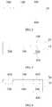
FIG. 1 is a flow chart of a position method in micromachining process for a bulk silicon according to an embodiment;FIG. 2 is a perspective view of a first substrate after a second alignment mark for a double-sided lithography machine is fabricated;FIG. 3 is a perspective view of a second substrate after a third alignment mark for a double-sided lithography machine is fabricated;FIG. 4 is a perspective view of a second substrate after a recess and a first pattern are fabricated; andFIG. 5 is a flow chart of a position method in micromachining process for a bulk silicon according to another embodiment.- Embodiments of the invention are described more fully hereinafter with reference to the accompanying drawings, in which preferred embodiments of the invention are shown. The various embodiments of the invention may, however, be embodied in many different forms and should not be construed as limited to the embodiments set forth herein. Rather, these embodiments are provided so that this disclosure will be thorough and complete, and will fully convey the scope of the invention to those skilled in the art.
- Unless otherwise defined, all terms (including technical and scientific terms) used herein have the same meaning as commonly understood by one of ordinary skill in the art to which this invention belongs. Terms in the description of the invention are for the purpose of describing specific embodiments, and are not intend to limit the invention. As used herein, the term "and/or" includes any and all combinations of one or more of the associated listed items.
FIG. 1 is a flow chart of a position method in micromachining process for a bulk silicon according to an embodiment.- Referring to
FIG. 2 and FIG. 3 , a positioning method in micromachining process for a bulk silicon includes steps as follows: - In step S100, a
first pattern 100, a stepper lithographymachine alignment mark 200 configured to position thefirst pattern 100, and a first alignment mark for a double-sided lithography machine 300 configured to position the stepper lithographymachine alignment mark 200 are fabricated on a front surface of afirst substrate 10. Thefirst substrate 10 can be a silicon wafer. Thefirst pattern 100 is fabricated, the stepper lithographymachine alignment mark 200 which can position thefirst pattern 100 is fabricated, and the first alignment mark for a double-sided lithography machine 300 which can position the stepper lithographymachine alignment mark 200 is fabricated, i.e. a position of thefirst pattern 100 can be determined by the stepper lithographymachine alignment mark 200, a position of the stepper lithographymachine alignment mark 200 can be determined by the first alignment mark for a double-sided lithography machine 300. The number of the stepper lithographymachine alignment mark 200 should be multiple, and preferably, it is at least 5 to guarantee relative high alignment accuracy. The number of the first alignment marks for a double-sided lithography machine 300 is at least 2 to guarantee relative high alignment accuracy. - In step S200, a second alignment mark for a double-
sided lithography machine 400 corresponding to the first alignment mark for a double-sided lithography machine 300 is fabricated on a rear surface of thefirst substrate 10. The "corresponding to" herein is "having a position corresponding to", i.e. a position of the first alignment mark for a double-sided lithography machine 300 on the front surface of thefirst substrate 10 is corresponding to a position of the second alignment mark for a double-sided lithography machine 400 on the rear surface.FIG. 2 is a perspective view of a first substrate after a second alignment mark for a double-sided lithography machine is fabricated. - In step S300, a
second substrate 20 is bonded on the front surface of thefirst substrate 10. Thesecond substrate 20 is made of material which is same as that of thefirst substrate 10, and thesecond substrate 20 is a silicon wafer. - In step S400, a grinding process is performed to the front surface of the
second substrate 20. The grinding process is applied to the front surface to reach a required thickness of the device. - In step S500, a third alignment mark for a double-
sided lithography machine 500 corresponding to the second alignment mark for a double-sided lithography machine 400 is fabricated on the front surface of thesecond substrate 20. The double-sided lithography machine is adopted to fabricate the third alignment mark for a double-sided lithography machine 500 corresponding to the second alignment mark for a double-sided lithography machine 400 on the front surface of thesecond substrate 20 by the second alignment mark for a double-sided lithography machine 400 on the rear surface of thefirst substrate 10. The "corresponding to" herein is "having a position corresponding to", i.e. the third alignment mark for a double-sided lithography machine 500 on the front surface of thesecond substrate 20 has a position corresponding to that of the second alignment mark for a double-sided lithography machine 400 on the rear surface of thefirst substrate 10.FIG. 3 is a perspective view of a second substrate after a third alignment mark for a double-sided lithography machine is fabricated. - In step S600, a position corresponding to the stepper lithography
machine alignment mark 200 is found on a front surface of thesecond substrate 20 by the third alignment mark for a double-sided lithography machine 500. The specific principle is that, the position of the second alignment mark for a double-sided lithography machine 400 can be determined according to the third alignment mark for a double-sided lithography machine 500, and then the first alignment mark for a double-sided lithography machine 300 can be determined according to the second alignment mark for a double-sided lithography machine 400, and then the position of the stepper lithographymachine alignment mark 200 can be determined according to the first alignment mark for a double-sided lithography machine 300. - The advantageous effect of the determination of the stepper lithography
machine alignment mark 200 is that, the position of thefirst pattern 100 can be determined by the stepper lithographymachine alignment mark 200 again in the following steps, such that asecond pattern 700 corresponding to the position of thefirst pattern 100 can be fabricated. A method combining the double-sided lithography to the stepper lithography is adopted, the position of the stepper lithographymachine alignment mark 200 of the stepper lithography machine on the first substrate is found by the double-sided lithography machine, and then an alignment is performed to thesecond substrate 20 directly by the stepper lithography machine. The alignment accuracy of the stepper lithography machine is equivalent to an alignment accuracy of the patterns (thefirst pattern 100 and the second pattern 700) on surfaces of the upper/lower substrate (thefirst substrate 10 and the second substrate 20), such that the alignment accuracy of the micromachining process for a bulk silicon is improved greatly. It is specifically illustrated with reference to the following embodiments. FIG. 5 is a flow chart of a position method in micromachining process for a bulk silicon according to another embodiment.- A positioning method in micromachining process for a bulk silicon includes steps as follows:
- In step S110, a
first pattern 100, a stepper lithographymachine alignment mark 200 configured to position thefirst pattern 100, and a first alignment mark for a double-sided lithography machine 300 configured to position the stepper lithographymachine alignment mark 200 are fabricated on a first surface (the front surface in the embodiment) of afirst substrate 10. Thefirst substrate 10 can be a silicon wafer. Thefirst pattern 100 is fabricated, the stepper lithographymachine alignment mark 200 which can position thefirst pattern 100 is fabricated, and the first alignment mark for a double-sided lithography machine 300 which can position the stepper lithographymachine alignment mark 200 is fabricated, i.e. a position of thefirst pattern 100 can be determined merely by the stepper lithographymachine alignment mark 200, a position of the stepper lithographymachine alignment mark 200 can be determined by the first alignment mark for a double-sided lithography machine 300. The number of the stepper lithographymachine alignment marks 200 should be multiple, and preferably, it is at least 5 to guarantee relative high alignment accuracy. The number of the first alignment mark for a double-sided lithography machine 300 is at least 2 to guarantee relative high alignment accuracy. - In step S120, a second alignment mark for a double-
sided lithography machine 400 corresponding to the first alignment mark for a double-sided lithography machine 300 is fabricated on a second surface (the rear surface in the embodiment) of thefirst substrate 10. The "corresponding to" herein is "having a position corresponding to", i.e. a position of the first alignment mark for a double-sided lithography machine 300 on the front surface of thesubstrate 10 is corresponding to a position of the second alignment mark for a double-sided lithography machine 400 on the rear surface, as shown inFIG. 2 . - In step S130, a
second substrate 20 is bonded on the front surface of thefirst substrate 10. Thesecond substrate 20 is made of material which is same as that of thefirst substrate 10, and thesecond substrate 20 is a silicon wafer. - In step S140, a grinding process is performed to a first surface (the front surface in the embodiment) of the
second substrate 20. - In step S150, a third alignment mark for a double-
sided lithography machine 500 corresponding to the second alignment mark for a double-sided lithography machine 400 is fabricated on the front surface of thesecond substrate 20. The double-sided lithography machine is adopted to fabricate the third alignment mark for a double-sided lithography machine 500 corresponding to the second alignment mark for a double-sided lithography machine 400 on the front surface of thesecond substrate 20 by virtue of the second alignment mark for a double-sided lithography machine 400 on the rear surface of thefirst substrate 10. The "corresponding to" herein is "having a position corresponding to", i.e. the third alignment mark for a double-sided lithography machine 500 on the front surface of thesecond substrate 20 has a position corresponding to that of the second alignment mark for a double-sided lithography machine 400 on the rear surface of thefirst substrate 10, as shown inFIG. 3 . - In step S160, a position corresponding to the stepper lithography
machine alignment mark 200 is found on the front surface of thesecond substrate 20 by the third alignment mark for a double-sided lithography machine 500. The specific principle is that, the position of the second alignment mark for a double-sided lithography machine 400 can be determined according to the third alignment mark for a double-sided lithography machine 500, and then the first alignment mark for a double-sided lithography machine 300 can be determined according to the second alignment mark for a double-sided lithography machine 400, and then the position of the stepper lithographymachine alignment mark 200 can be determined according to the first alignment mark for a double-sided lithography machine 300 - In step S170, a
recess 600 is fabricated on the position corresponding to the stepper lithographymachine alignment mark 200 on the front surface of thesecond substrate 20, to expose the stepper lithographymachine alignment mark 200 on the front surface of thefirst substrate 10 . A part of the substrate corresponding to stepper lithographymachine alignment mark 200 on the front surface of thesecond substrate 20 is removed, the stepper lithographymachine alignment mark 200 below thesecond substrate 20 is exposed. The removing method can be performed by using stepper lithography machine through etching technology, such as dry etching or wet etching. - In step S180, a position corresponding to the
first pattern 100 on the front surface of thesecond substrate 20 is found by the stepper lithographymachine alignment mark 200, and asecond pattern 700 is fabricated on the position corresponding to thefirst pattern 100. Because the position of thefirst pattern 100 can be determined by the stepper lithographymachine alignment mark 200, therefore, thesecond pattern 700 fabricated on thesecond substrate 20 by the stepper lithographymachine alignment mark 200 has a position corresponding to thefirst pattern 100 on thefirst substrate 10, an accurate alignment can be achieved.FIG. 4 is a perspective view of a second substrate after a recess and a first pattern is fabricated, referring toFIG. 4 . - In aforementioned positioning method in micromachining process for a bulk silicon, a method combining the double-sided lithography to the stepper lithography is adopted, the stepper lithography machine alignment mark of the stepper lithography machine on the first substrate is found by the double-sided lithography machine, and then the second substrate is directly aligned by the stepper lithography machine. The alignment accuracy of the stepper lithography machine is equivalent to an alignment accuracy of the patterns on surfaces of the upper/lower substrate, such that the alignment accuracy of the micromachining process for a bulk silicon is improved greatly. The stepper lithography machine is an integrated optic-mechanical-electron system which gathers precision optics, precision mechanics and automatic controls, the alignment accuracy can be less than 0.5 micrometers, therefore, the alignment accuracy of the micromachining process for a bulk silicon can be less than 0.5 micrometers.
- The above are several embodiments of the present invention described in detail, and should not be deemed as limitations to the scope of the present invention. It should be noted that variations and improvements will become apparent to those skilled in the art to which the present invention pertains without departing from its spirit and scope. Therefore, the scope of the present invention is defined by the appended claims.
Claims (8)
- A positioning method in micromachining process for a bulk silicon, comprising:fabricating a first pattern, a stepper lithography machine alignment mark configured to position the first pattern, and a first alignment mark for a double-sided lithography machine configured to position the stepper lithography machine alignment mark on a first surface of a first substrate;fabricating a second alignment mark for a double-sided lithography machine corresponding to the first alignment mark for a double-sided lithography machine on a second surface of the first substrate opposite to the first surface;bonding a second substrate on the first surface of the first substrate;performing a grinding process to a first surface of the second substrate;fabricating a third alignment mark for a double-sided lithography machine corresponding to the second alignment mark for a double-sided lithography machine on the first surface of the second substrate; andfinding a position corresponding to the stepper lithography machine alignment mark by the third alignment mark for a double-sided lithography machine on the first surface of the second substrate.
- The method according to claim 1, further comprising: removing a part of the second substrate corresponding to the stepper lithography machine alignment mark, thereby exposing the stepper lithography machine alignment mark on the first surface of the first substrate.
- The method according to claim 2, further comprising: finding a position corresponding to the first pattern on the first surface of the second substrate by the stepper lithography machine alignment mark, and fabricating a second pattern on the position corresponding to the first pattern.
- The method according to claim 2, wherein the part of the second substrate on the position corresponding to the stepper lithography machine alignment mark is removed by etching technology.
- The method according to claim 4, wherein removing the part of the second substrate on the position corresponding to the stepper lithography machine alignment mark comprises using a stepper lithography machine to perform lithography.
- The method according to claim 1, wherein a number of the stepper lithography machine alignment marks is at least five.
- The method according to claim 1, wherein a number of the first alignment marks of the double-sided lithography machine is at least two.
- The method according to claim 1, wherein the first substrate and the second substrate are silicon wafers.
Applications Claiming Priority (2)
| Application Number | Priority Date | Filing Date | Title |
|---|---|---|---|
| CN201410660920.6ACN105645347B (en) | 2014-11-18 | 2014-11-18 | The localization method of bulk-micromachining |
| PCT/CN2015/087528WO2016078452A1 (en) | 2014-11-18 | 2015-08-19 | Positioning method in microprocessing process of bulk silicon |
Publications (3)
| Publication Number | Publication Date |
|---|---|
| EP3098196A1 EP3098196A1 (en) | 2016-11-30 |
| EP3098196A4 EP3098196A4 (en) | 2017-12-06 |
| EP3098196B1true EP3098196B1 (en) | 2019-03-27 |
Family
ID=56013250
Family Applications (1)
| Application Number | Title | Priority Date | Filing Date |
|---|---|---|---|
| EP15860320.9AActiveEP3098196B1 (en) | 2014-11-18 | 2015-08-19 | Positioning method in microprocessing process of bulk silicon |
Country Status (4)
| Country | Link |
|---|---|
| US (1) | US9902613B2 (en) |
| EP (1) | EP3098196B1 (en) |
| CN (1) | CN105645347B (en) |
| WO (1) | WO2016078452A1 (en) |
Families Citing this family (5)
| Publication number | Priority date | Publication date | Assignee | Title |
|---|---|---|---|---|
| CN109761190B (en)* | 2019-01-22 | 2021-03-02 | 上海华虹宏力半导体制造有限公司 | Method for forming alignment mark |
| CN115176415A (en)* | 2020-04-09 | 2022-10-11 | 株式会社村田制作所 | Method for manufacturing collective substrate and collective substrate |
| CN112542413B (en)* | 2020-12-03 | 2021-09-28 | 中国电子科技集团公司第五十五研究所 | Alignment method for heterogeneous substrate semiconductor thin film device |
| CN114695223A (en)* | 2020-12-25 | 2022-07-01 | 上海新微技术研发中心有限公司 | Method for double-sided thinning and alignment of bonded wafers |
| CN113808985B (en)* | 2021-09-02 | 2024-06-11 | 中国电子科技集团公司第五十五研究所 | Heterogeneous substrate film transfer alignment method |
Family Cites Families (14)
| Publication number | Priority date | Publication date | Assignee | Title |
|---|---|---|---|---|
| KR100276429B1 (en)* | 1998-09-07 | 2000-12-15 | 정선종 | Fabricatuon method of micro vacuum structure |
| US6582985B2 (en)* | 2000-12-27 | 2003-06-24 | Honeywell International Inc. | SOI/glass process for forming thin silicon micromachined structures |
| EP1406126A1 (en)* | 2001-01-15 | 2004-04-07 | ASML Netherlands B.V. | Device manufacturing method |
| US6525805B2 (en)* | 2001-05-14 | 2003-02-25 | Ultratech Stepper, Inc. | Backside alignment system and method |
| US7528937B1 (en)* | 2002-08-05 | 2009-05-05 | Ultratech, Inc. | Dual-sided substrate measurement apparatus and methods |
| EP1477861A1 (en)* | 2003-05-16 | 2004-11-17 | ASML Netherlands B.V. | A method of calibrating a lithographic apparatus, an alignment method, a computer program, a lithographic apparatus and a device manufacturing method |
| DE102005015584B4 (en)* | 2005-04-05 | 2010-09-02 | Litef Gmbh | Method for producing a micromechanical component |
| CN101436006B (en) | 2008-12-17 | 2011-10-12 | 上海微电子装备有限公司 | Double-surface position alignment apparatus and method |
| CN101905856B (en) | 2010-06-11 | 2012-10-10 | 北京大学 | Method for preparing plane hollow microneedle for transdermal administration |
| CN102556956B (en)* | 2012-03-08 | 2014-06-25 | 中国科学院上海微系统与信息技术研究所 | Vacuum packaging structure of MEMS (Micro Electro Mechanical System) device and manufacture method thereof |
| US8822141B1 (en)* | 2013-03-05 | 2014-09-02 | International Business Machines Corporation | Front side wafer ID processing |
| US9041213B2 (en)* | 2013-03-14 | 2015-05-26 | Freescale Semiconductor Inc. | Microelectromechanical system devices having through substrate vias and methods for the fabrication thereof |
| CN103558740A (en)* | 2013-10-24 | 2014-02-05 | 华东光电集成器件研究所 | Double-surface stepping photo-etching method for micro electro mechanical system (MEMS) wafer |
| CN104078405A (en)* | 2014-06-24 | 2014-10-01 | 上海天英微系统科技有限公司 | Photoetching alignment method and wafers |
- 2014
- 2014-11-18CNCN201410660920.6Apatent/CN105645347B/enactiveActive
- 2015
- 2015-08-19USUS15/315,640patent/US9902613B2/enactiveActive
- 2015-08-19EPEP15860320.9Apatent/EP3098196B1/enactiveActive
- 2015-08-19WOPCT/CN2015/087528patent/WO2016078452A1/enactiveApplication Filing
Non-Patent Citations (1)
| Title |
|---|
| None* |
Also Published As
| Publication number | Publication date |
|---|---|
| EP3098196A1 (en) | 2016-11-30 |
| US20170113930A1 (en) | 2017-04-27 |
| CN105645347B (en) | 2017-08-08 |
| WO2016078452A1 (en) | 2016-05-26 |
| EP3098196A4 (en) | 2017-12-06 |
| US9902613B2 (en) | 2018-02-27 |
| CN105645347A (en) | 2016-06-08 |
Similar Documents
| Publication | Publication Date | Title |
|---|---|---|
| EP3098196B1 (en) | Positioning method in microprocessing process of bulk silicon | |
| JP5240185B2 (en) | Work stage of exposure machine, exposure method, and structure manufacturing method | |
| US20080248600A1 (en) | Method and device for wafer backside alignment overlay accuracy | |
| TWI760104B (en) | A method of clamping a substrate to a clamping system, a substrate holder and a substrate support | |
| TW201116478A (en) | Method for manufacturing microstructures | |
| US7563720B2 (en) | Boron doped shell for MEMS device | |
| TWI741257B (en) | Patterned vacuum chuck for double-sided processing | |
| WO2013185605A1 (en) | Alignment mark and fabrication method thereof | |
| TWI792180B (en) | Substrate holder for use in a lithographic apparatus | |
| US8283256B1 (en) | Methods of forming microdevice substrates using double-sided alignment techniques | |
| CN104062707B (en) | The manufacture method of optical fiber align pedestal array | |
| CN104249992B (en) | Alignment methods between wafer and wafer | |
| CN105182681A (en) | Mask plate and method for processing various depth structures on same silicon wafer | |
| CN106653578B (en) | Wafer processing method | |
| CN108008608B (en) | A method of backside alignment | |
| CN104370266B (en) | The film build method of inductive material in deep trench | |
| CN104570630B (en) | Photoetching alignment mark and forming method thereof | |
| JP2004177149A (en) | Micro-dimensional standard sample and manufacturing method thereof | |
| CN106444303B (en) | A kind of sample clamp and application for alignment function in micro-nano device micro-group dress | |
| JPS6324617A (en) | Double-sided wafer exposure method | |
| JP2001230232A (en) | Method for detecting etching end point of semiconductor substrate | |
| JP6456114B2 (en) | Substrate transport method, substrate transport apparatus, lithography apparatus, and article manufacturing method | |
| Brabender et al. | Wafer Extension For Cost-Effective front to Back Side Alignment | |
| US7029830B2 (en) | Precision and apertures for lithographic systems | |
| TW505972B (en) | A pre-etching pattern to determine crystal orientation on silicon wafer |
Legal Events
| Date | Code | Title | Description |
|---|---|---|---|
| PUAI | Public reference made under article 153(3) epc to a published international application that has entered the european phase | Free format text:ORIGINAL CODE: 0009012 | |
| 17P | Request for examination filed | Effective date:20160822 | |
| AK | Designated contracting states | Kind code of ref document:A1 Designated state(s):AL AT BE BG CH CY CZ DE DK EE ES FI FR GB GR HR HU IE IS IT LI LT LU LV MC MK MT NL NO PL PT RO RS SE SI SK SM TR | |
| AX | Request for extension of the european patent | Extension state:BA ME | |
| A4 | Supplementary search report drawn up and despatched | Effective date:20171107 | |
| RIC1 | Information provided on ipc code assigned before grant | Ipc:H01L 21/68 20060101ALI20171030BHEP Ipc:G03F 9/00 20060101ALI20171030BHEP Ipc:B81C 3/00 20060101ALI20171030BHEP Ipc:B81C 1/00 20060101AFI20171030BHEP | |
| DAV | Request for validation of the european patent (deleted) | ||
| DAX | Request for extension of the european patent (deleted) | ||
| GRAP | Despatch of communication of intention to grant a patent | Free format text:ORIGINAL CODE: EPIDOSNIGR1 | |
| STAA | Information on the status of an ep patent application or granted ep patent | Free format text:STATUS: GRANT OF PATENT IS INTENDED | |
| INTG | Intention to grant announced | Effective date:20181016 | |
| GRAS | Grant fee paid | Free format text:ORIGINAL CODE: EPIDOSNIGR3 | |
| GRAA | (expected) grant | Free format text:ORIGINAL CODE: 0009210 | |
| STAA | Information on the status of an ep patent application or granted ep patent | Free format text:STATUS: THE PATENT HAS BEEN GRANTED | |
| AK | Designated contracting states | Kind code of ref document:B1 Designated state(s):AL AT BE BG CH CY CZ DE DK EE ES FI FR GB GR HR HU IE IS IT LI LT LU LV MC MK MT NL NO PL PT RO RS SE SI SK SM TR | |
| REG | Reference to a national code | Ref country code:GB Ref legal event code:FG4D | |
| REG | Reference to a national code | Ref country code:CH Ref legal event code:EP | |
| REG | Reference to a national code | Ref country code:AT Ref legal event code:REF Ref document number:1112818 Country of ref document:AT Kind code of ref document:T Effective date:20190415 | |
| REG | Reference to a national code | Ref country code:IE Ref legal event code:FG4D | |
| REG | Reference to a national code | Ref country code:DE Ref legal event code:R096 Ref document number:602015027360 Country of ref document:DE | |
| REG | Reference to a national code | Ref country code:DE Ref legal event code:R082 Ref document number:602015027360 Country of ref document:DE Representative=s name:MANITZ FINSTERWALD PATENT- UND RECHTSANWALTSPA, DE Ref country code:DE Ref legal event code:R081 Ref document number:602015027360 Country of ref document:DE Owner name:CSMC TECHNOLOGIES FAB2 CO., LTD., WUXI, CN Free format text:FORMER OWNER: CSMC TECHNOLOGIES FAB1 CO., LTD., WUXI, JIANGSU, CN | |
| RAP2 | Party data changed (patent owner data changed or rights of a patent transferred) | Owner name:CSMC TECHNOLOGIES FAB2 CO., LTD. | |
| REG | Reference to a national code | Ref country code:NL Ref legal event code:FP | |
| REG | Reference to a national code | Ref country code:NL Ref legal event code:PD Owner name:CSMC TECHNOLOGIES FAB2 CO., LTD.; CN Free format text:DETAILS ASSIGNMENT: CHANGE OF OWNER(S), ASSIGNMENT; FORMER OWNER NAME: CSMC TECHNOLOGIES FAB1 CO., LTD. Effective date:20190611 | |
| PG25 | Lapsed in a contracting state [announced via postgrant information from national office to epo] | Ref country code:SE Free format text:LAPSE BECAUSE OF FAILURE TO SUBMIT A TRANSLATION OF THE DESCRIPTION OR TO PAY THE FEE WITHIN THE PRESCRIBED TIME-LIMIT Effective date:20190327 Ref country code:FI Free format text:LAPSE BECAUSE OF FAILURE TO SUBMIT A TRANSLATION OF THE DESCRIPTION OR TO PAY THE FEE WITHIN THE PRESCRIBED TIME-LIMIT Effective date:20190327 Ref country code:LT Free format text:LAPSE BECAUSE OF FAILURE TO SUBMIT A TRANSLATION OF THE DESCRIPTION OR TO PAY THE FEE WITHIN THE PRESCRIBED TIME-LIMIT Effective date:20190327 Ref country code:NO Free format text:LAPSE BECAUSE OF FAILURE TO SUBMIT A TRANSLATION OF THE DESCRIPTION OR TO PAY THE FEE WITHIN THE PRESCRIBED TIME-LIMIT Effective date:20190627 | |
| REG | Reference to a national code | Ref country code:GB Ref legal event code:732E Free format text:REGISTERED BETWEEN 20190718 AND 20190724 | |
| PG25 | Lapsed in a contracting state [announced via postgrant information from national office to epo] | Ref country code:RS Free format text:LAPSE BECAUSE OF FAILURE TO SUBMIT A TRANSLATION OF THE DESCRIPTION OR TO PAY THE FEE WITHIN THE PRESCRIBED TIME-LIMIT Effective date:20190327 Ref country code:BG Free format text:LAPSE BECAUSE OF FAILURE TO SUBMIT A TRANSLATION OF THE DESCRIPTION OR TO PAY THE FEE WITHIN THE PRESCRIBED TIME-LIMIT Effective date:20190627 Ref country code:GR Free format text:LAPSE BECAUSE OF FAILURE TO SUBMIT A TRANSLATION OF THE DESCRIPTION OR TO PAY THE FEE WITHIN THE PRESCRIBED TIME-LIMIT Effective date:20190628 Ref country code:LV Free format text:LAPSE BECAUSE OF FAILURE TO SUBMIT A TRANSLATION OF THE DESCRIPTION OR TO PAY THE FEE WITHIN THE PRESCRIBED TIME-LIMIT Effective date:20190327 Ref country code:HR Free format text:LAPSE BECAUSE OF FAILURE TO SUBMIT A TRANSLATION OF THE DESCRIPTION OR TO PAY THE FEE WITHIN THE PRESCRIBED TIME-LIMIT Effective date:20190327 | |
| REG | Reference to a national code | Ref country code:AT Ref legal event code:MK05 Ref document number:1112818 Country of ref document:AT Kind code of ref document:T Effective date:20190327 | |
| PG25 | Lapsed in a contracting state [announced via postgrant information from national office to epo] | Ref country code:AL Free format text:LAPSE BECAUSE OF FAILURE TO SUBMIT A TRANSLATION OF THE DESCRIPTION OR TO PAY THE FEE WITHIN THE PRESCRIBED TIME-LIMIT Effective date:20190327 Ref country code:EE Free format text:LAPSE BECAUSE OF FAILURE TO SUBMIT A TRANSLATION OF THE DESCRIPTION OR TO PAY THE FEE WITHIN THE PRESCRIBED TIME-LIMIT Effective date:20190327 Ref country code:IT Free format text:LAPSE BECAUSE OF FAILURE TO SUBMIT A TRANSLATION OF THE DESCRIPTION OR TO PAY THE FEE WITHIN THE PRESCRIBED TIME-LIMIT Effective date:20190327 Ref country code:RO Free format text:LAPSE BECAUSE OF FAILURE TO SUBMIT A TRANSLATION OF THE DESCRIPTION OR TO PAY THE FEE WITHIN THE PRESCRIBED TIME-LIMIT Effective date:20190327 Ref country code:SK Free format text:LAPSE BECAUSE OF FAILURE TO SUBMIT A TRANSLATION OF THE DESCRIPTION OR TO PAY THE FEE WITHIN THE PRESCRIBED TIME-LIMIT Effective date:20190327 Ref country code:ES Free format text:LAPSE BECAUSE OF FAILURE TO SUBMIT A TRANSLATION OF THE DESCRIPTION OR TO PAY THE FEE WITHIN THE PRESCRIBED TIME-LIMIT Effective date:20190327 Ref country code:CZ Free format text:LAPSE BECAUSE OF FAILURE TO SUBMIT A TRANSLATION OF THE DESCRIPTION OR TO PAY THE FEE WITHIN THE PRESCRIBED TIME-LIMIT Effective date:20190327 Ref country code:PT Free format text:LAPSE BECAUSE OF FAILURE TO SUBMIT A TRANSLATION OF THE DESCRIPTION OR TO PAY THE FEE WITHIN THE PRESCRIBED TIME-LIMIT Effective date:20190727 | |
| PG25 | Lapsed in a contracting state [announced via postgrant information from national office to epo] | Ref country code:PL Free format text:LAPSE BECAUSE OF FAILURE TO SUBMIT A TRANSLATION OF THE DESCRIPTION OR TO PAY THE FEE WITHIN THE PRESCRIBED TIME-LIMIT Effective date:20190327 Ref country code:SM Free format text:LAPSE BECAUSE OF FAILURE TO SUBMIT A TRANSLATION OF THE DESCRIPTION OR TO PAY THE FEE WITHIN THE PRESCRIBED TIME-LIMIT Effective date:20190327 | |
| PG25 | Lapsed in a contracting state [announced via postgrant information from national office to epo] | Ref country code:IS Free format text:LAPSE BECAUSE OF FAILURE TO SUBMIT A TRANSLATION OF THE DESCRIPTION OR TO PAY THE FEE WITHIN THE PRESCRIBED TIME-LIMIT Effective date:20190727 Ref country code:AT Free format text:LAPSE BECAUSE OF FAILURE TO SUBMIT A TRANSLATION OF THE DESCRIPTION OR TO PAY THE FEE WITHIN THE PRESCRIBED TIME-LIMIT Effective date:20190327 | |
| REG | Reference to a national code | Ref country code:DE Ref legal event code:R097 Ref document number:602015027360 Country of ref document:DE | |
| PG25 | Lapsed in a contracting state [announced via postgrant information from national office to epo] | Ref country code:DK Free format text:LAPSE BECAUSE OF FAILURE TO SUBMIT A TRANSLATION OF THE DESCRIPTION OR TO PAY THE FEE WITHIN THE PRESCRIBED TIME-LIMIT Effective date:20190327 | |
| PLBE | No opposition filed within time limit | Free format text:ORIGINAL CODE: 0009261 | |
| STAA | Information on the status of an ep patent application or granted ep patent | Free format text:STATUS: NO OPPOSITION FILED WITHIN TIME LIMIT | |
| PG25 | Lapsed in a contracting state [announced via postgrant information from national office to epo] | Ref country code:SI Free format text:LAPSE BECAUSE OF FAILURE TO SUBMIT A TRANSLATION OF THE DESCRIPTION OR TO PAY THE FEE WITHIN THE PRESCRIBED TIME-LIMIT Effective date:20190327 | |
| 26N | No opposition filed | Effective date:20200103 | |
| PG25 | Lapsed in a contracting state [announced via postgrant information from national office to epo] | Ref country code:TR Free format text:LAPSE BECAUSE OF FAILURE TO SUBMIT A TRANSLATION OF THE DESCRIPTION OR TO PAY THE FEE WITHIN THE PRESCRIBED TIME-LIMIT Effective date:20190327 | |
| PG25 | Lapsed in a contracting state [announced via postgrant information from national office to epo] | Ref country code:LU Free format text:LAPSE BECAUSE OF NON-PAYMENT OF DUE FEES Effective date:20190819 Ref country code:CH Free format text:LAPSE BECAUSE OF NON-PAYMENT OF DUE FEES Effective date:20190831 Ref country code:LI Free format text:LAPSE BECAUSE OF NON-PAYMENT OF DUE FEES Effective date:20190831 Ref country code:MC Free format text:LAPSE BECAUSE OF FAILURE TO SUBMIT A TRANSLATION OF THE DESCRIPTION OR TO PAY THE FEE WITHIN THE PRESCRIBED TIME-LIMIT Effective date:20190327 | |
| REG | Reference to a national code | Ref country code:BE Ref legal event code:MM Effective date:20190831 | |
| PG25 | Lapsed in a contracting state [announced via postgrant information from national office to epo] | Ref country code:IE Free format text:LAPSE BECAUSE OF NON-PAYMENT OF DUE FEES Effective date:20190819 | |
| PG25 | Lapsed in a contracting state [announced via postgrant information from national office to epo] | Ref country code:BE Free format text:LAPSE BECAUSE OF NON-PAYMENT OF DUE FEES Effective date:20190831 | |
| PG25 | Lapsed in a contracting state [announced via postgrant information from national office to epo] | Ref country code:CY Free format text:LAPSE BECAUSE OF FAILURE TO SUBMIT A TRANSLATION OF THE DESCRIPTION OR TO PAY THE FEE WITHIN THE PRESCRIBED TIME-LIMIT Effective date:20190327 | |
| PG25 | Lapsed in a contracting state [announced via postgrant information from national office to epo] | Ref country code:MT Free format text:LAPSE BECAUSE OF FAILURE TO SUBMIT A TRANSLATION OF THE DESCRIPTION OR TO PAY THE FEE WITHIN THE PRESCRIBED TIME-LIMIT Effective date:20190327 Ref country code:HU Free format text:LAPSE BECAUSE OF FAILURE TO SUBMIT A TRANSLATION OF THE DESCRIPTION OR TO PAY THE FEE WITHIN THE PRESCRIBED TIME-LIMIT; INVALID AB INITIO Effective date:20150819 | |
| PG25 | Lapsed in a contracting state [announced via postgrant information from national office to epo] | Ref country code:MK Free format text:LAPSE BECAUSE OF FAILURE TO SUBMIT A TRANSLATION OF THE DESCRIPTION OR TO PAY THE FEE WITHIN THE PRESCRIBED TIME-LIMIT Effective date:20190327 | |
| PGFP | Annual fee paid to national office [announced via postgrant information from national office to epo] | Ref country code:GB Payment date:20240612 Year of fee payment:10 | |
| PGFP | Annual fee paid to national office [announced via postgrant information from national office to epo] | Ref country code:FR Payment date:20240612 Year of fee payment:10 | |
| PGFP | Annual fee paid to national office [announced via postgrant information from national office to epo] | Ref country code:NL Payment date:20240821 Year of fee payment:10 | |
| PGFP | Annual fee paid to national office [announced via postgrant information from national office to epo] | Ref country code:DE Payment date:20240819 Year of fee payment:10 |