EP3098182A1 - Vial with non-round seal - Google Patents
Vial with non-round sealDownload PDFInfo
- Publication number
- EP3098182A1 EP3098182A1EP16177910.3AEP16177910AEP3098182A1EP 3098182 A1EP3098182 A1EP 3098182A1EP 16177910 AEP16177910 AEP 16177910AEP 3098182 A1EP3098182 A1EP 3098182A1
- Authority
- EP
- European Patent Office
- Prior art keywords
- lid
- container
- sealing surface
- dispensing opening
- seated
- Prior art date
- Legal status (The legal status is an assumption and is not a legal conclusion. Google has not performed a legal analysis and makes no representation as to the accuracy of the status listed.)
- Granted
Links
Images


Classifications
- B—PERFORMING OPERATIONS; TRANSPORTING
- B65—CONVEYING; PACKING; STORING; HANDLING THIN OR FILAMENTARY MATERIAL
- B65D—CONTAINERS FOR STORAGE OR TRANSPORT OF ARTICLES OR MATERIALS, e.g. BAGS, BARRELS, BOTTLES, BOXES, CANS, CARTONS, CRATES, DRUMS, JARS, TANKS, HOPPERS, FORWARDING CONTAINERS; ACCESSORIES, CLOSURES, OR FITTINGS THEREFOR; PACKAGING ELEMENTS; PACKAGES
- B65D43/00—Lids or covers for rigid or semi-rigid containers
- B65D43/14—Non-removable lids or covers
- B65D43/16—Non-removable lids or covers hinged for upward or downward movement
- B65D43/162—Non-removable lids or covers hinged for upward or downward movement the container, the lid and the hinge being made of one piece
- B—PERFORMING OPERATIONS; TRANSPORTING
- B01—PHYSICAL OR CHEMICAL PROCESSES OR APPARATUS IN GENERAL
- B01L—CHEMICAL OR PHYSICAL LABORATORY APPARATUS FOR GENERAL USE
- B01L3/00—Containers or dishes for laboratory use, e.g. laboratory glassware; Droppers
- B01L3/50—Containers for the purpose of retaining a material to be analysed, e.g. test tubes
- B01L3/508—Containers for the purpose of retaining a material to be analysed, e.g. test tubes rigid containers not provided for above
- B01L3/5082—Test tubes per se
- B01L3/50825—Closing or opening means, corks, bungs
- B—PERFORMING OPERATIONS; TRANSPORTING
- B29—WORKING OF PLASTICS; WORKING OF SUBSTANCES IN A PLASTIC STATE IN GENERAL
- B29C—SHAPING OR JOINING OF PLASTICS; SHAPING OF MATERIAL IN A PLASTIC STATE, NOT OTHERWISE PROVIDED FOR; AFTER-TREATMENT OF THE SHAPED PRODUCTS, e.g. REPAIRING
- B29C39/00—Shaping by casting, i.e. introducing the moulding material into a mould or between confining surfaces without significant moulding pressure; Apparatus therefor
- B29C39/02—Shaping by casting, i.e. introducing the moulding material into a mould or between confining surfaces without significant moulding pressure; Apparatus therefor for making articles of definite length, i.e. discrete articles
- B29C39/021—Shaping by casting, i.e. introducing the moulding material into a mould or between confining surfaces without significant moulding pressure; Apparatus therefor for making articles of definite length, i.e. discrete articles by casting in several steps
- B—PERFORMING OPERATIONS; TRANSPORTING
- B65—CONVEYING; PACKING; STORING; HANDLING THIN OR FILAMENTARY MATERIAL
- B65D—CONTAINERS FOR STORAGE OR TRANSPORT OF ARTICLES OR MATERIALS, e.g. BAGS, BARRELS, BOTTLES, BOXES, CANS, CARTONS, CRATES, DRUMS, JARS, TANKS, HOPPERS, FORWARDING CONTAINERS; ACCESSORIES, CLOSURES, OR FITTINGS THEREFOR; PACKAGING ELEMENTS; PACKAGES
- B65D81/00—Containers, packaging elements, or packages, for contents presenting particular transport or storage problems, or adapted to be used for non-packaging purposes after removal of contents
- B65D81/24—Adaptations for preventing deterioration or decay of contents; Applications to the container or packaging material of food preservatives, fungicides, pesticides or animal repellants
- B65D81/26—Adaptations for preventing deterioration or decay of contents; Applications to the container or packaging material of food preservatives, fungicides, pesticides or animal repellants with provision for draining away, or absorbing, or removing by ventilation, fluids, e.g. exuded by contents; Applications of corrosion inhibitors or desiccators
- B65D81/266—Adaptations for preventing deterioration or decay of contents; Applications to the container or packaging material of food preservatives, fungicides, pesticides or animal repellants with provision for draining away, or absorbing, or removing by ventilation, fluids, e.g. exuded by contents; Applications of corrosion inhibitors or desiccators for absorbing gases, e.g. oxygen absorbers or desiccants
- G—PHYSICS
- G01—MEASURING; TESTING
- G01N—INVESTIGATING OR ANALYSING MATERIALS BY DETERMINING THEIR CHEMICAL OR PHYSICAL PROPERTIES
- G01N33/00—Investigating or analysing materials by specific methods not covered by groups G01N1/00 - G01N31/00
- G01N33/48—Biological material, e.g. blood, urine; Haemocytometers
- G01N33/483—Physical analysis of biological material
- G01N33/487—Physical analysis of biological material of liquid biological material
- G01N33/4875—Details of handling test elements, e.g. dispensing or storage, not specific to a particular test method
- G01N33/48778—Containers specially adapted therefor, e.g. for dry storage
- B—PERFORMING OPERATIONS; TRANSPORTING
- B01—PHYSICAL OR CHEMICAL PROCESSES OR APPARATUS IN GENERAL
- B01L—CHEMICAL OR PHYSICAL LABORATORY APPARATUS FOR GENERAL USE
- B01L2200/00—Solutions for specific problems relating to chemical or physical laboratory apparatus
- B01L2200/06—Fluid handling related problems
- B01L2200/0689—Sealing
- B—PERFORMING OPERATIONS; TRANSPORTING
- B01—PHYSICAL OR CHEMICAL PROCESSES OR APPARATUS IN GENERAL
- B01L—CHEMICAL OR PHYSICAL LABORATORY APPARATUS FOR GENERAL USE
- B01L2200/00—Solutions for specific problems relating to chemical or physical laboratory apparatus
- B01L2200/14—Process control and prevention of errors
- B01L2200/141—Preventing contamination, tampering
- B—PERFORMING OPERATIONS; TRANSPORTING
- B01—PHYSICAL OR CHEMICAL PROCESSES OR APPARATUS IN GENERAL
- B01L—CHEMICAL OR PHYSICAL LABORATORY APPARATUS FOR GENERAL USE
- B01L2200/00—Solutions for specific problems relating to chemical or physical laboratory apparatus
- B01L2200/14—Process control and prevention of errors
- B01L2200/142—Preventing evaporation
- B—PERFORMING OPERATIONS; TRANSPORTING
- B01—PHYSICAL OR CHEMICAL PROCESSES OR APPARATUS IN GENERAL
- B01L—CHEMICAL OR PHYSICAL LABORATORY APPARATUS FOR GENERAL USE
- B01L2300/00—Additional constructional details
- B01L2300/04—Closures and closing means
- B01L2300/041—Connecting closures to device or container
- B01L2300/043—Hinged closures
- B—PERFORMING OPERATIONS; TRANSPORTING
- B01—PHYSICAL OR CHEMICAL PROCESSES OR APPARATUS IN GENERAL
- B01L—CHEMICAL OR PHYSICAL LABORATORY APPARATUS FOR GENERAL USE
- B01L2300/00—Additional constructional details
- B01L2300/06—Auxiliary integrated devices, integrated components
- B01L2300/0609—Holders integrated in container to position an object
- B—PERFORMING OPERATIONS; TRANSPORTING
- B01—PHYSICAL OR CHEMICAL PROCESSES OR APPARATUS IN GENERAL
- B01L—CHEMICAL OR PHYSICAL LABORATORY APPARATUS FOR GENERAL USE
- B01L2300/00—Additional constructional details
- B01L2300/08—Geometry, shape and general structure
- B01L2300/0809—Geometry, shape and general structure rectangular shaped
- B01L2300/0825—Test strips
- B—PERFORMING OPERATIONS; TRANSPORTING
- B01—PHYSICAL OR CHEMICAL PROCESSES OR APPARATUS IN GENERAL
- B01L—CHEMICAL OR PHYSICAL LABORATORY APPARATUS FOR GENERAL USE
- B01L2300/00—Additional constructional details
- B01L2300/12—Specific details about materials
- B01L2300/123—Flexible; Elastomeric
- B—PERFORMING OPERATIONS; TRANSPORTING
- B01—PHYSICAL OR CHEMICAL PROCESSES OR APPARATUS IN GENERAL
- B01L—CHEMICAL OR PHYSICAL LABORATORY APPARATUS FOR GENERAL USE
- B01L9/00—Supporting devices; Holding devices
- B01L9/52—Supports specially adapted for flat sample carriers, e.g. for plates, slides, chips
- B—PERFORMING OPERATIONS; TRANSPORTING
- B29—WORKING OF PLASTICS; WORKING OF SUBSTANCES IN A PLASTIC STATE IN GENERAL
- B29C—SHAPING OR JOINING OF PLASTICS; SHAPING OF MATERIAL IN A PLASTIC STATE, NOT OTHERWISE PROVIDED FOR; AFTER-TREATMENT OF THE SHAPED PRODUCTS, e.g. REPAIRING
- B29C43/00—Compression moulding, i.e. applying external pressure to flow the moulding material; Apparatus therefor
- B29C43/02—Compression moulding, i.e. applying external pressure to flow the moulding material; Apparatus therefor of articles of definite length, i.e. discrete articles
- B29C43/14—Compression moulding, i.e. applying external pressure to flow the moulding material; Apparatus therefor of articles of definite length, i.e. discrete articles in several steps
- B—PERFORMING OPERATIONS; TRANSPORTING
- B65—CONVEYING; PACKING; STORING; HANDLING THIN OR FILAMENTARY MATERIAL
- B65D—CONTAINERS FOR STORAGE OR TRANSPORT OF ARTICLES OR MATERIALS, e.g. BAGS, BARRELS, BOTTLES, BOXES, CANS, CARTONS, CRATES, DRUMS, JARS, TANKS, HOPPERS, FORWARDING CONTAINERS; ACCESSORIES, CLOSURES, OR FITTINGS THEREFOR; PACKAGING ELEMENTS; PACKAGES
- B65D2251/00—Details relating to container closures
- B65D2251/20—Sealing means
- B—PERFORMING OPERATIONS; TRANSPORTING
- B65—CONVEYING; PACKING; STORING; HANDLING THIN OR FILAMENTARY MATERIAL
- B65D—CONTAINERS FOR STORAGE OR TRANSPORT OF ARTICLES OR MATERIALS, e.g. BAGS, BARRELS, BOTTLES, BOXES, CANS, CARTONS, CRATES, DRUMS, JARS, TANKS, HOPPERS, FORWARDING CONTAINERS; ACCESSORIES, CLOSURES, OR FITTINGS THEREFOR; PACKAGING ELEMENTS; PACKAGES
- B65D2543/00—Lids or covers essentially for box-like containers
- B65D2543/00009—Details of lids or covers for rigid or semi-rigid containers
- B65D2543/00018—Overall construction of the lid
- B65D2543/00064—Shape of the outer periphery
- B65D2543/0012—Shape of the outer periphery having straight sides, e.g. with curved corners
- B65D2543/00129—Shape of the outer periphery having straight sides, e.g. with curved corners two straight sides and at least one curved side
- B65D2543/00148—Shape of the outer periphery having straight sides, e.g. with curved corners two straight sides and at least one curved side with two curved sides
- B—PERFORMING OPERATIONS; TRANSPORTING
- B65—CONVEYING; PACKING; STORING; HANDLING THIN OR FILAMENTARY MATERIAL
- B65D—CONTAINERS FOR STORAGE OR TRANSPORT OF ARTICLES OR MATERIALS, e.g. BAGS, BARRELS, BOTTLES, BOXES, CANS, CARTONS, CRATES, DRUMS, JARS, TANKS, HOPPERS, FORWARDING CONTAINERS; ACCESSORIES, CLOSURES, OR FITTINGS THEREFOR; PACKAGING ELEMENTS; PACKAGES
- B65D2543/00—Lids or covers essentially for box-like containers
- B65D2543/00009—Details of lids or covers for rigid or semi-rigid containers
- B65D2543/00018—Overall construction of the lid
- B65D2543/00259—Materials used
- B65D2543/00296—Plastic
- B—PERFORMING OPERATIONS; TRANSPORTING
- B65—CONVEYING; PACKING; STORING; HANDLING THIN OR FILAMENTARY MATERIAL
- B65D—CONTAINERS FOR STORAGE OR TRANSPORT OF ARTICLES OR MATERIALS, e.g. BAGS, BARRELS, BOTTLES, BOXES, CANS, CARTONS, CRATES, DRUMS, JARS, TANKS, HOPPERS, FORWARDING CONTAINERS; ACCESSORIES, CLOSURES, OR FITTINGS THEREFOR; PACKAGING ELEMENTS; PACKAGES
- B65D2543/00—Lids or covers essentially for box-like containers
- B65D2543/00009—Details of lids or covers for rigid or semi-rigid containers
- B65D2543/00444—Contact between the container and the lid
- B65D2543/00481—Contact between the container and the lid on the inside or the outside of the container
- B65D2543/00537—Contact between the container and the lid on the inside or the outside of the container on the outside, or a part turned to the outside of the mouth of the container
- B—PERFORMING OPERATIONS; TRANSPORTING
- B65—CONVEYING; PACKING; STORING; HANDLING THIN OR FILAMENTARY MATERIAL
- B65D—CONTAINERS FOR STORAGE OR TRANSPORT OF ARTICLES OR MATERIALS, e.g. BAGS, BARRELS, BOTTLES, BOXES, CANS, CARTONS, CRATES, DRUMS, JARS, TANKS, HOPPERS, FORWARDING CONTAINERS; ACCESSORIES, CLOSURES, OR FITTINGS THEREFOR; PACKAGING ELEMENTS; PACKAGES
- B65D2543/00—Lids or covers essentially for box-like containers
- B65D2543/00009—Details of lids or covers for rigid or semi-rigid containers
- B65D2543/00444—Contact between the container and the lid
- B65D2543/00564—Contact between the container and the lid indirect by means of a gasket or similar intermediate ring
- B—PERFORMING OPERATIONS; TRANSPORTING
- B65—CONVEYING; PACKING; STORING; HANDLING THIN OR FILAMENTARY MATERIAL
- B65D—CONTAINERS FOR STORAGE OR TRANSPORT OF ARTICLES OR MATERIALS, e.g. BAGS, BARRELS, BOTTLES, BOXES, CANS, CARTONS, CRATES, DRUMS, JARS, TANKS, HOPPERS, FORWARDING CONTAINERS; ACCESSORIES, CLOSURES, OR FITTINGS THEREFOR; PACKAGING ELEMENTS; PACKAGES
- B65D2543/00—Lids or covers essentially for box-like containers
- B65D2543/00009—Details of lids or covers for rigid or semi-rigid containers
- B65D2543/00444—Contact between the container and the lid
- B65D2543/00592—Snapping means
- B65D2543/00601—Snapping means on the container
- B65D2543/00611—Profiles
- B65D2543/00629—Massive bead
- B—PERFORMING OPERATIONS; TRANSPORTING
- B65—CONVEYING; PACKING; STORING; HANDLING THIN OR FILAMENTARY MATERIAL
- B65D—CONTAINERS FOR STORAGE OR TRANSPORT OF ARTICLES OR MATERIALS, e.g. BAGS, BARRELS, BOTTLES, BOXES, CANS, CARTONS, CRATES, DRUMS, JARS, TANKS, HOPPERS, FORWARDING CONTAINERS; ACCESSORIES, CLOSURES, OR FITTINGS THEREFOR; PACKAGING ELEMENTS; PACKAGES
- B65D2543/00—Lids or covers essentially for box-like containers
- B65D2543/00009—Details of lids or covers for rigid or semi-rigid containers
- B65D2543/00444—Contact between the container and the lid
- B65D2543/00592—Snapping means
- B65D2543/00601—Snapping means on the container
- B65D2543/00675—Periphery concerned
- B65D2543/00685—Totality
- B—PERFORMING OPERATIONS; TRANSPORTING
- B65—CONVEYING; PACKING; STORING; HANDLING THIN OR FILAMENTARY MATERIAL
- B65D—CONTAINERS FOR STORAGE OR TRANSPORT OF ARTICLES OR MATERIALS, e.g. BAGS, BARRELS, BOTTLES, BOXES, CANS, CARTONS, CRATES, DRUMS, JARS, TANKS, HOPPERS, FORWARDING CONTAINERS; ACCESSORIES, CLOSURES, OR FITTINGS THEREFOR; PACKAGING ELEMENTS; PACKAGES
- B65D2543/00—Lids or covers essentially for box-like containers
- B65D2543/00009—Details of lids or covers for rigid or semi-rigid containers
- B65D2543/00444—Contact between the container and the lid
- B65D2543/00592—Snapping means
- B65D2543/00712—Snapping means on the lid
- B65D2543/00722—Profiles
- B65D2543/0074—Massive bead
- B—PERFORMING OPERATIONS; TRANSPORTING
- B65—CONVEYING; PACKING; STORING; HANDLING THIN OR FILAMENTARY MATERIAL
- B65D—CONTAINERS FOR STORAGE OR TRANSPORT OF ARTICLES OR MATERIALS, e.g. BAGS, BARRELS, BOTTLES, BOXES, CANS, CARTONS, CRATES, DRUMS, JARS, TANKS, HOPPERS, FORWARDING CONTAINERS; ACCESSORIES, CLOSURES, OR FITTINGS THEREFOR; PACKAGING ELEMENTS; PACKAGES
- B65D2543/00—Lids or covers essentially for box-like containers
- B65D2543/00009—Details of lids or covers for rigid or semi-rigid containers
- B65D2543/00444—Contact between the container and the lid
- B65D2543/00592—Snapping means
- B65D2543/00712—Snapping means on the lid
- B65D2543/00787—Periphery concerned
- B65D2543/00796—Totality
- B—PERFORMING OPERATIONS; TRANSPORTING
- B65—CONVEYING; PACKING; STORING; HANDLING THIN OR FILAMENTARY MATERIAL
- B65D—CONTAINERS FOR STORAGE OR TRANSPORT OF ARTICLES OR MATERIALS, e.g. BAGS, BARRELS, BOTTLES, BOXES, CANS, CARTONS, CRATES, DRUMS, JARS, TANKS, HOPPERS, FORWARDING CONTAINERS; ACCESSORIES, CLOSURES, OR FITTINGS THEREFOR; PACKAGING ELEMENTS; PACKAGES
- B65D2543/00—Lids or covers essentially for box-like containers
- B65D2543/00009—Details of lids or covers for rigid or semi-rigid containers
- B65D2543/00824—Means for facilitating removing of the closure
- B65D2543/00833—Integral tabs, tongues, handles or similar
- B65D2543/00842—Integral tabs, tongues, handles or similar outside of the lid
- B—PERFORMING OPERATIONS; TRANSPORTING
- B65—CONVEYING; PACKING; STORING; HANDLING THIN OR FILAMENTARY MATERIAL
- B65D—CONTAINERS FOR STORAGE OR TRANSPORT OF ARTICLES OR MATERIALS, e.g. BAGS, BARRELS, BOTTLES, BOXES, CANS, CARTONS, CRATES, DRUMS, JARS, TANKS, HOPPERS, FORWARDING CONTAINERS; ACCESSORIES, CLOSURES, OR FITTINGS THEREFOR; PACKAGING ELEMENTS; PACKAGES
- B65D2543/00—Lids or covers essentially for box-like containers
- B65D2543/00009—Details of lids or covers for rigid or semi-rigid containers
- B65D2543/00953—Sealing means
- B65D2543/00962—Sealing means inserted
Definitions
- the present disclosurerelates to containers that can be used, for example, to house test strips, pills, capsules, particulate materials, liquids, or other objects or materials and control the ingress and/or egress of moisture.
- This patent applicationdiscloses technology related to that of U.S. Ser. No. 29/318,272, filed May 16, 2008 . That patent application is incorporated here by reference.
- Cylindrical containersare described in the following patents as being "leak-proof:" U.S. Patent Nos. 4,783,056 , 4,812,116 , RE 37,676 and 6,303,064 .
- U.S. Patents 6,769,558 and 7,198,161 and European patent 1 220 794all to the present inventor, disclose a leakproof, resealable cylindrical container and cap assembly. The disclosure of the processes of producing injection molded plastic containers and sealing them are incorporated by reference herein.
- An aspect of the inventionis a moisture proof, resealable non-cylindrical container and lid assembly.
- the term "resealable"means that the closure can be closed at least once after the container is opened for the first time. Preferably, the closure can be opened and closed additional times after the initial opening to remove all of the contents.
- the containerhas a body having an interior space, defined by a generally tubular sidewall.
- the bodyhas a lid, and the lid and body have a non-round seal that is substantially moisture proof when the lid is seated on the body, meaning that when sealed the container admits less than 1000 micrograms per day of water determined by a moisture ingress test method.
- the containeroptionally is sized as a pharmaceutical package enclosing between 1 and 500 ml of interior volume, alternatively between 10 and 200 ml of interior volume, alternatively between 20 and 100 ml of internal volume.
- the bodyhas a generally tubular sidewall with first and second axially opposed ends, a base, and a dispensing opening axially spaced from the base and at least adjacent to the second end.
- the interior spaceis disposed generally within the sidewall and at least generally between the base and the dispensing opening.
- the sidewallhas a cross-section having a major diameter and a minor diameter, wherein the ratio between the major diameter and the minor diameter of the sidewall cross-section is a value between 1.1 : 1 and 10 : 1, inclusive.
- the containerhas a non-round body sealing surface located on the body and disposed about the dispensing opening, the body sealing surface having a major diameter and a minor diameter, wherein the ratio between the major diameter and the minor diameter of the body sealing surface is a value between 1.1 : 1 and 10 : 1, inclusive.
- the lidis configured to seat on the body. There is a lid sealing surface located on the lid.
- the body sealing surface and the lid sealing surfaceare configured to mate to form a seal between the lid and the body when the lid is seated on the body.
- the lid and lid sealing surfaceat least substantially close the dispensing opening and isolate the interior space from ambient conditions.
- An insertcommunicates with the interior space of the container and reinforces at least a portion of the body sealing surface against inward deflection along an axis defined by the minor diameter when the lid is seated on the body.
- the containerhas a moisture ingress rate of the container having a moisture ingress rate of 100-1000 micrograms per day, optionally 200-700 micrograms per day, optionally 380- 700 micrograms per day, optionally 400-700 micrograms per day, optionally 250- 400 micrograms per day, optionally less than 300 micrograms per day, at 80% relative humidity and 72 °F (22.2°C).
- the interior spaceis defined at least in part by an interior surface made of a desiccant material.
- the interior spaceis defined at least in part by a reinforcement stiffening the container against deflection along the minor axis.
- the reinforcementis an insert assembled with the container.
- the insertis secured to the container by an interference fit between the insert and the inner wall of the container
- the insertis made of a desiccant material.
- the insertis disposed within the container.
- the insertis a liner generally following the inner wall of the container.
- At least one of the ends of the containerhas an interior portion made of desiccant material.
- the sidewallhas an interior portion made of desiccant material.
- the lidhas an interior portion made of desiccant material.
- At least a portion of the desiccant materialis located in the interior space.
- At least a portion of the desiccantis a particulate material.
- At least a portion of the desiccantis provided in the form of one or more sachets.
- At least a portion of the desiccantis provided in the form of one or more canisters.
- At least a portion of the desiccantis provided in the form of one or more pellets.
- the containerfurther comprises a sleeve of desiccant material disposed within the body and at least partially defining the interior space.
- the sleeveis integrally formed with at least one of the sidewall and an end wall.
- the containerfurther comprises a tether linking the container body and lid.
- the tethercomprises a hinge.
- the tethercomprises an integral hinge.
- the hingeis configured to orient the lid to seat on the body when the lid and body are pivoted together.
- the hingedefines a pivot axis that is generally perpendicular to the major axis.
- the hingedefines a pivot axis that is generally parallel to the major axis.
- the hingeextends from the sidewall at least adjacent to the end of the major axis.
- the hingeextends from the sidewall at least adjacent to the end of the minor axis.
- the bodyis at least generally oval in cross-section.
- the bodyis at least generally polygonal in cross-section.
- the bodyis at least generally rectangular in cross-section.
- the bodyhas at least one rounded corner.
- At least a portion of the dispensing openingis defined by the second end of the sidewall.
- the lidcomprises a closed surface supporting the lid sealing surface.
- the lidcomprises a skirt surrounding and depending from the lid sealing surface.
- the skirtis generally tubular.
- the skirt cross-sectionis substantially congruent to the cross-section of the body sidewall, at least substantially defining an extension of the generally tubular sidewall when the lid is seated on the body.
- the ratio between the major diameter and the minor diameter of the cross-section of the body sidewallis a value between 1.5 : 1 and 5 : 1, inclusive.
- the ratio between the major diameter and the minor diameter of the cross-section of the sidewallis a value between 1.5 : 1 and 4 : 1, inclusive.
- the ratio between the major diameter and the minor diameter of the cross-section of the sidewallis a value between 1.5 : 1 and 3 : 1, inclusive.
- the ratio between the major diameter and the minor diameter of the cross-section of the sidewallis a value between 2 : 1 and 5 : 1, inclusive.
- the ratio between the major diameter and the minor diameter of the cross-section of the sidewallis a value between 2 : 1 and 4:1, inclusive.
- the ratio between the major diameter and the minor diameter of the cross-section of the sidewallis a value between 2 : 1 and 3 : 1, inclusive.
- the ratio between the major diameter and the minor diameter of the cross-section of the body sidewallis a value between 1.5 : 1 and 5 : 1, inclusive.
- the ratio between the major diameter and the minor diameter of the cross-section of the body sealing surfaceis a value between 1.5 : 1 and 4 : 1, inclusive.
- the ratio between the major diameter and the minor diameter of the cross-section of the body sealing surfaceis a value between 1.5 : 1 and 3 : 1, inclusive.
- the ratio between the major diameter and the minor diameter of the cross-section of the body sealing surfaceis a value between 2 : 1 and 5 : 1, inclusive.
- the ratio between the major diameter and the minor diameter of the cross-section of the body sealing surfaceis a value between 2 : 1 and 4 : 1, inclusive.
- the ratio between the major diameter and the minor diameter of the cross-section of the body sealing surfaceis a value between 2 : 1 and 3 : 1, inclusive.
- At least a portion of the body and at least a portion of the lidare formed in one shot in an injection mold.
- the body and the lidare formed in two shots in an injection mold.
- the respective shotsare a substantially moisture blocking polymeric material and a desiccant polymeric material.
- a dispenser for strips of materialcomprising a generally tubular body, a first platform, a second platform, and at least one spline.
- the bodyhas an interior surface and first and second axially opposed ends, at least one of the ends defining a dispensing opening.
- the first platformextends laterally within the interior surface and positioned at the first end or between the first and second ends of the body.
- the second platformextends laterally within the interior surface, is positioned between and spaced axially from the first platform and the dispensing opening, and defines a reservoir between the second platform and the dispensing opening and a region between the first and second platforms.
- the splineextends axially and laterally within the reservoir and subdivides the reservoir into plural axially extending reservoirs communicating with the dispensing opening.
- At least one open path of communicationis a perforation in the second platform.
- the desiccant materialis in contact with the region.
- the regionis defined by an interior surface composed at least in part of a desiccant material.
- At least a portion of at least one of the body interior surface, a spline, the first platform, and the second platformis composed of a desiccant material.
- At least a portion of the body interior surfaceis composed of a desiccant material.
- At least a portion of at least one splineis composed of a desiccant material.
- At least a portion of the first platformis composed of a desiccant material.
- At least a portion of the second platformis composed of a desiccant material.
- the body and at least one of the first platform, the second platform, and a splineare integral.
- the body and the first platformare integral.
- the body and the second platformare integral.
- the body and a splineare integral.
- the body and each splineare integral.
- the body and each of the first platform, the second platform, and the splinesare injection molded.
- At least a portion of the body and at least a portion of the first platformare formed in one shot in an injection mold.
- the second platform and splinesare formed in one shot in an injection mold.
- At least a portion of the body and the first platformare formed in a first shot in an injection mold and the second platform and splines are formed in a second shot in an injection mold.
- the portions formed in the first shotdefine a first part
- the portions formed in the second shotdefine a second part
- the first and second partsare joined together to define a dispenser.
- the desiccantis a particulate material.
- the desiccantis provided in the form of one or more sachets, canisters, or pellets.
- first seal surface on the capthere is a first seal surface on the cap and a second seal surface on the body, the seal surfaces being mateable to at least substantially seal the dispensing opening.
- a desiccant materialdisposed within the cap.
- a sleeve of desiccant materialdisposed within the body and at least partially defining at least one of the reservoir and region.
- the sleeveis integrally formed with at least one of the first and second platforms.
- the second platformhas a first portion defining a first strip reservoir.
- the second platformfurther comprises a second portion non-coplanar with the first portion defining a second strip reservoir.
- the second strip reservoiris axially longer than the first strip reservoir.
- the bodyis generally oval in cross-section.
- the splineslie substantially parallel to the laterally extending long axis of the oval.
- the splineslie substantially parallel to the laterally extending short axis of the oval.
- first and second axesthere are perpendicular laterally extending first and second axes, further comprising one or more strips of material in at least one of the reservoirs oriented with their major faces substantially parallel to the first axis.
- first and second axesthere are perpendicular laterally extending first and second axes, further comprising one or more strips of material in at least one of the reservoirs oriented with their major faces substantially parallel to the second axis.
- Another aspect of the inventionis a method of making dispensers for objects of varying length to customize particular dispensers to dispense such objects of a particular length. The method is carried out in several steps.
- One stepis providing a first injection mold cavity adapted to form a generally tubular body having an interior surface; first and second axially opposed ends, at least one of the ends defining a dispensing opening; and a first platform extending laterally within the interior surface and positioned between the axially opposed ends of the body.
- Another stepis providing a second injection mold cavity adapted to form an insert sized and configured to fit within the generally tubular body, the insert having a second platform configured to be positioned between and spaced axially from the first platform and the dispensing opening when the insert is assembled with the body, defining a reservoir between the second platform and the dispensing opening and a region between the first and second platforms.
- a third stepis modifying at least one of the first and second injection mold cavities to place the first and second platforms of the tubular body and the insert in relative axial positions adapted to support objects of a specific length on the second platform at a predetermined position relative to the dispensing opening.
- the second injection mold cavityis modified.
- the first injection mold cavityis not modified to customize the dispenser.
- U.S. Patents 6,769,558 and 7,198,161 and European patent 1 220 794all to the present inventor, disclose a leakproof, resealable, flip-top cylindrical container and cap assembly which comprises a cap and container attached by a hinge. A user is readily able to close the lid using the front tab on the lid.
- Those patentsare incorporated here by reference for the characteristics and dimensions of a suitable seal for a container and cap assembly.
- the closureWhen forming a moisture-tight seal using the flip-top closure described in the foregoing patents, the closure exerts a compressive force about the top of the container body. A sealing relationship is formed between the closure and the container body.
- the seal effectivenessis due to the stiffness of the container walls.
- the wallsbecome less stiff against inward and outward deflection along the minor axis and are not able to withstand the force exerted by the closure.
- This lack of stiffnessresults in less seal integrity (i.e., a higher moisture ingress rate).
- the seal area of the sidewall of the container or capis particularly subject to flexing along the minor axis, where the opposed walls have the largest radius in an oval container.
- the present inventorhas further determined that this problem can be addressed by providing a reinforcement stiffening the container against deflection along the minor axis.
- the reinforcementcan be extra material in the container wall itself, but can also be provided, for example by press-fitting or otherwise incorporating an insert or liner into the container to reinforce its portions at or near the beginning and end of the minor axis.
- the insertwhich also has utility to orient test strips, may be used to stiffen the sidewalls of the container.
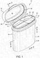
- a vial or container 10including a body 12, an interior space 14, a body sealing surface 16, a lid 18, a lid sealing surface 20, and a desiccant material 22 communicating with the interior space 14.
- the body 12can have a generally tubular sidewall 24 with first and second axially opposed ends 26 and 28 and a dispensing opening 30.
- the dispensing opening 30is axially spaced from the first end or base 26 and at least adjacent to the second end 28. In the embodiment of Figures 1-4 , at least a portion of the dispensing opening 30 is defined by the second end 28 of the sidewall 24.
- the body 12can have its interior space 14 disposed generally within the sidewall 24 and at least generally between the base 26 and the dispensing opening 30.
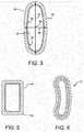
- the generally tubular sidewall 24can have a cross-section 32, best shown in Figure 3 , having a major diameter 34 and a minor diameter 36 each passing through the center 38.
- the ratio between the major diameter 34 and the minor diameter 36 of the cross-section 32can be, for example, a value between 1.1 : 1 and 10 : 1, inclusive.
- the ratio between the major diameter 34 and the minor diameter 36 of the cross-section 32 of the body sidewall 24can be a value between 1.5 : 1 and 5 : 1, alternatively between 1.5 : 1 and 4 : 1, alternatively between 1.5 : 1 and 4 : 1, alternatively between 1.5 : 1 and 3 : 1, alternatively between 2 : 1 and 5 : 1, alternatively between 2 : 1 and 4 : 1, alternatively between 2 : 1 and 3 : 1, alternatively between 1.5 : 1 and 5 : 1, in each case the end points being inclusive.
- the upper and lower limitsare not critical; the point of the ratios is to provide a container 10 that is wider than it is deep, or vice versa.
- the body 12is at least generally oval in cross-section 32.
- the bodycan have other cross-sectional configurations.
- the body 44can be at least generally polygonal in cross-section, or at least generally rectangular in cross-section, and alternatively can have at least one rounded corner 46.
- the containercan be configured as shown in the container 47 of Figure 1 , with opposing concave and convex walls.
- the body sealing surface 16is not round, is located on the body 12, and is disposed about the dispensing opening 30.
- the body sealing surface 16can have a major diameter 40 and a minor diameter 42, and the ratio between the major diameter 40 and the minor diameter 42 of the body sealing surface 16 can be a value between 1.1 : 1 and 10 : 1, inclusive.
- the ratio between the major diameter 40 and the minor diameter 42 of the body sealing surface 16can be between 1.5 : 1 and 4 : 1, alternatively between 1.5 : 1 and 3 : 1, alternatively between 1.5 : 1 and 2 : 1, alternatively between 2 : 1 and 5 : 1, alternatively between 2 : 1 and 4 : 1, alternatively between 2 : 1 and 3 : 1, in each case the end points being inclusive.
- the upper and lower limitsagain are not critical, and provide a non-round sealing surface.
- the ratio of the major and minor cross-section diameters 34 and 36can be the same as or different from the ratio of the major and minor diameters 40 and 42 of the body sealing surface 16.
- the shapes of the body sealing surface 16 and the cross-section 32can be the same or different.
- the cross-section 32could be rectangular with rounded corners and the body sealing surface 16 could be elliptical. This is just one illustration of a possible alternative configuration.
- the lid 18comprises a closed surface 48 supporting the lid sealing surface 20.
- the lid 18can be configured to seat on the body 12. It can have a lid sealing surface 20.
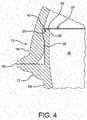
- the body sealing surface 16 and the lid sealing surface 20can be configured to mate to form a seal 50 (best seen in Figure 4 ) between the lid 18 and the body 12 when the lid 18 is seated on the body 12.
- the seal 50is formed, the lid 18 and the seal 50 defined by the sealing surfaces 16 and 20 at least substantially close the dispensing opening 30 and isolate the interior space 14 from ambient conditions.
- the lid 18 of Figures 1-4can have a generally tubular skirt 52 surrounding and depending from the lid sealing surface 20.
- the cross-section of the skirt 52can be substantially congruent to the cross-section 32 of the body sidewall, at least substantially defining an extension of the generally tubular sidewall 24 when the lid 18 is seated on the body 12, as shown in Figure 4 .
- a tetherhere configured as an integral hinge 54, links the body 12 and the lid 18.
- the hinge 54can be configured to orient the lid 18 to seat on the body 12 when the lid 18 and body 12 are pivoted together.
- the illustrated integral hinge 54 of Figures 1-4can extend from the sidewall 24 of the body 12 at least adjacent to the end of the minor axis 42.
- the integral hinge as illustrateddefines a pivot axis 54 that can be generally parallel to the major diameter 40.
- the integral hingecould be displaced 90 degrees circumferentially and extend from the sidewall 24 of the body 12 at least adjacent to the end of the major diameter 40.
- the integral hingecould then define a pivot axis that could be generally perpendicular to the major axis 40.
- the integral hingecould also be displaced to an intermediate point between the ends of the major diameter 40 and minor diameter 42, in another alternative embodiment, providing an oblique pivot axis parallel neither to the major diameter 40 nor the minor diameter 42.
- a non-round sealfor example the seal 50 shown in Figures 1-4 formed by mating the non-round body sealing surface 16 and lid sealing surface 20, does not exclude moisture as well as a round seal. Nonetheless, it may be necessary or useful to limit the amount of moisture entering or leaving the interior space 14 of the container 10, as when the contents of the container 10 are moisture-sensitive.
- the inventorshave found that the issue of moisture sensitivity caused by a non-round seal can be addressed and at least partially alleviated if the container 10 includes a desiccant material such as 22 communicating with the interior space 14 of the container 10 when the lid 18 is seated on the body 12.
- desiccant material 22is the injection-moldable thermoplastic desiccant polymeric material described in one or more of US. Patent Nos. 5,911,937 ; 6,214,255 ; 6,130,263 ; 6,080,350 ; 6,174,952 ; 6,124,006 ; and 6,221,446 , all to Hekal. These patents are incorporated here by reference. Silica gel, a molecular sieve, calcium oxides or clay may also or instead be used directly as desiccants or incorporated into a desiccant material.
- the desiccantalternatively can be a material adapted to release a gas, such as an inert gas that prevents oxidation of the enclosed medicament, a flavoring or fragrance, or moisture, in the case of a medicament that should not be allowed to dry out.
- a gassuch as an inert gas that prevents oxidation of the enclosed medicament, a flavoring or fragrance, or moisture, in the case of a medicament that should not be allowed to dry out.
- the interior space 14can be defined at least in part by an interior surface 58 of the body 12 made of a desiccant material 22.
- at least one of the ends of the container 10, here the first end 26,also can have an interior portion 60 made of desiccant material.
- the lid 18can have an interior portion 48 that can be integrally molded of desiccant material 22.
- the interior surface 58 of desiccant 22can be defined by a separately molded sleeve of desiccant material 22 placed within the body 12 and at least partially defining the interior space 14. The sleeve can be integrally formed with at least one of the sidewall and an end wall.
- At least a portion of the desiccant material 22can located in the interior space 14.
- at least a portion of the desiccant 22can be provided in the form of one or more sachets 64, or canisters 66, or a particulate material 68, which can be provided as pellets or in other particulate forms.
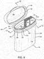
- a secondary seal generally indicated at 78is disclosed for a container 80 otherwise similar to that of Figures 1-4 .
- the lid 18has an inner skirt 82 and the body 12 contains a desiccant insert 22 and a generally annular seal gasket 84 having a sealing surface 86 encircling the contents 88 of the container.
- the inner skirt 82has a distal or lower end 90 bearing against the seal gasket 84, forming the seal.
- the seal gasket 84can be made of an elastomeric material (for example a thermoplastic elastomer, TPE.)
- TPEthermoplastic elastomer
- One contemplated TPEis Santoprene®, which is a registered trademark of Monsanto Company of St. Louis, Missouri, U.S.A.
- the position of the lower end 90 of the web 82, and thus the seal 78,can be closer to the outer skirt 52 of the lid than illustrated in Figure 7 , which may be useful to allow more space within the inner seal 80.
- the gasket 86can alternatively be reduced to just the portion beneath the lower end 90 of the inner skirt 82, although an advantage of the illustrated embodiment is that the material of the seal gasket 84 can also isolate the top surface of the desiccant material 22 from direct contact with the environment when the container 80 is opened.
- an elastomermay also be located along the top interior surface of the vial body 12, such as the body sealing surface 16, to resiliently seat against the lid sealing surface 20.
- a secondary sealing elementcan also or alternatively be formed along the inside surface of the flip-top lid 18.
- the secondary sealing elementmay be located in close proximity to the sidewall or skirt 52 of the flip-top lid 18. When the lid 18 is closed, the secondary sealing element compresses the elastomer along the top surface of the insert to form a secondary seal, in combination with the seal according to U.S. Patent 6,769,558 and other patents as previously described.
- any one or more of the desiccant or sealing features shown in the Figurescan be used individually or together, and additional embodiments deploying the desiccant or sealing elements in other ways are also contemplated.
- the container 10can be made in various ways.
- the container 10 and its desiccant feature 22can each be separately injection molded from thermoplastic material, as in a one-shot or two-shot injection process, then assembled.
- the first moldis used to produce the flip-top vial 10 or 80.
- second moldan insert is molded.
- the lid 18 and integral hinge 54can be integrally formed in the same mold as the outer body 12.
- the flip-top vial lidis closed in the mold.
- the body 12 and the desiccant polymeric material 22can formed in two shots in one injection mold.
- the insertis composed of two materials: a desiccant plastic 22 and an elastomeric material 84.
- the insert 22 and seal gasket 84may be molded in a 2-shot injection molding process.
- the desiccant material 22 of the insertis formed in the first shot.
- the elastomeric material 84is formed in the second shot.
- the composite insertis assembled into the vial.
- the seal material and the material of the body 12 or lid 18can be formed in a single, two-shot mold.
- suitable material for the outer portions of the container 10can be polypropylene - a moisture blocking polymeric material.
- the outer body 12 and lid 18can be made of polypropylene, and the desiccant features such the interior portion 60 can be made of a desiccant material.
- the containercan also be made as disclosed in any of the embodiments of U.S. Ser. No. 61/053,277 or 29/318,272 , which are incorporated by reference above.
- the elastomeric material 84forms a secondary seal along the top interior surface of the vial flip-top lid.
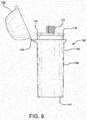
- the illustrated dispenser 120is a vial including a generally tubular body 126 and a lid 128 joined together by a hinge 130.
- the body 126is generally oval or elliptical in cross-section, having a laterally extending long axis 132 (running from top to bottom in Figure 10 ) and a laterally extending short axis 134 (running from side to side in Figure 10 ).
- the body 126, lid 128, and hinge 130can be integrally formed, as by molding the assembly in a one-shot injection mold to form the body 126, the lid 128, and an integral hinge 130 simultaneously.
- the body 126, lid 128, and hinge 130can be made of any suitable material, commonly a substantially moisture-impervious material and commonly a thermoplastic material that is useful for injection molding.
- the body 126, lid 128, and the hinge 130can be made of polypropylene or polyethylene, for example, to provide good moisture protection.
- the lid 128 and body 126respectively have first and second sealing locations 36 and 38 which are mateable when the lid 128 is seated on the body 126 to at least substantially seal the dispensing opening 142 and minimize contact of water vapor or other environmental substances with the test strips such as 122 and 124 or other contents of the dispenser 120.
- the body 126has an interior surface 140 and first and second axially opposed ends 142 and 144, and at least one of the ends, here the end 142, defines a dispensing opening.
- Figures 10-12in particular show various interior details of the embodiment of Figure 8 .
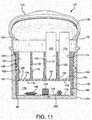
- the body 126has a first platform 146, in this embodiment defined by the upper surface of an integrally formed web 148.
- first platform 146extends laterally within the interior surface 140 and is positioned at least substantially at the end 44 of the body.
- the body 126has a second platform 150 extending laterally within the interior surface 140.
- the second platform 150is positioned between and spaced axially from the first platform 146 and the dispensing opening 142.
- the second platform 150is defined by the upper surface of a laterally extending web 152.
- the second platform 150is positioned and configured to provide adequate elevation to extend the test strips 122, 124 beyond the top lip or dispensing opening 142 of the vial body 126 and position them within the lid 128 (when closed) without damaging the exposed ends of the test strips. Damage could occur when the lid is closed and strips such as 122, 124 lean or bend over and get trapped between the vial body 126 and the lid 128.
- the end userBy extending the test strips 122, 124 beyond the dispensing opening 142 of the vial body, the end user will have substantially easier access to the test strips 122, 124 presented to the user when the vial lid 128 is open. Since commercial test strips have many different lengths, the second platform 150 of the dispenser 120 can be easily adjusted to the test strip length to consistently be able to provide a package that presents the test strips to the consumer uniformly, regardless of the test strip length, without necessarily changing the overall length of the generally tubular body 126.
- first and second platforms 146 and 150can provide a method to increase the amount of desiccant being used for enhanced shelf life protection. It is more difficult to obtain a moisture tight seal on the illustrated oval dispenser 120 than on a round dispenser.
- the platformsallow additional desiccant to be added to the dispenser 120 for enhanced shelf life protection.
- Oval vialsalso are more difficult to manufacture due to the difference in shrinkage of the primarily flat sides as opposed to the sharper corners on the ends. This non-uniform geometry causes differences in shrinkage rates compared to a round vial.
- a reservoir generally indicated at 154is located between the second platform 150 and the dispensing opening 142, and a region generally indicated at 156 is located between the first and second platforms 146 and 150.
- the splines 162, 164, and 166lie substantially parallel to the laterally extending short axis 134 of the oval.
- the splines such as 167 and 169could lie substantially parallel to the laterally extending long axis 132 of the oval.
- Partitioning the reservoir 154 using splines 162, 164, and 166allows discrete placement of the test strips 122, 124, keeping them neatly arranged and more compact than random placement. Additionally the splines 162, 164, and 166 assist in maintaining the test strips upright for presentation to the customer. Together with the body 126 and insert 190, the splines 162, 164, and 166 position the test strips 122, 124 away from the sealing locations 136 and 138 to prevent the test strips 122, 124 from being lodged between the sealing locations 136 and 138 while closing the lid 128.
- the dispenser 120can have an open path of communication, such as the platform perforations 176, 178, and 180 in the second platform 150 and web 152, between the reservoir 154 and at least one of the strip reservoirs, such as 168.
- an open path of communicationis provided between the reservoir 154 and each of the strip reservoirs 168, 170, 172, and 174.
- the body 126 and at least one of the first platform 146, the second platform 150, and a spline such as 162, 164, 166, and 168are integral.
- the body and the first platformare integral.
- the body 126includes an exterior shell 182, which can be made of moisture-impervious material integrally formed with the first platform 146 and web 148.
- the dispenser of Figures 8-12at least a portion of the body and at least a portion of the first platform are formed in one shot in an injection mold, forming a first part.
- a generally tubular liner 184is provided, here including the second platform 150 and the splines 162, 164, and 166. At least a portion of the second platform 150 and the splines 162, 164, and 166 are formed in a single shot in an injection mold, forming a second part. The first and second parts are assembled to provide a dispenser 120.
- the liner 184 of the embodiment shown in Figures 8-12has a lower end 186 that, in the illustrated embodiment, abuts the first platform 146 to locate the liner 184 precisely within the body 126.
- the axial distance between the second platform 150 and the dispensing opening 142can be selected by providing a lower end 186 that is spaced a corresponding distance from the second platform 150. This allows the dispenser 120 to be customized for strips 122 of a particular length without changing the mold used to form the exterior shell 182.
- each of these partscan be made, in whole or in part, in a one-shot injection mold, without the need for side draws or other complicated and expensive molding or machining techniques that would otherwise be needed to make such an extensively undercut part.
- the body 126 and each of the first platform 146, the second platform 150, and the splines 162, 164, 166, and 168are injection molded, although that is not an essential feature.
- a desiccantoptionally can be incorporated into the dispenser 120 to keep the partial pressure of water vapor within the dispenser 120 relatively low compared to ambient conditions.
- One objectivecan be to reduce the partial pressure of water vapor in the reservoir 154 where the strips such as 122 and 124 are stored.
- a desiccantcan be provided anywhere within the enclosure formed by the exterior shell 182, including but not limited to on an interior surface 188 of the shell 182 itself.
- the shell 182could be partially or entirely molded from an injection moldable desiccant composition.
- Suitable desiccant plasticsinclude, but are not limited to, those disclosed in US. Patent Nos. 5,911,937 ; 6,214,255 ; 6,130,263 ; 6,080,350 ; 6,174,952 ; 6,124,006 ; and 6,221,446 , all to Hekal. These disclosures of these patents are incorporated herein by reference. Silica gel, a molecular sieve, calcium oxides or clay may be used directly as desiccants or incorporated into a desiccant material.
- the desiccantcan also or instead be a material adapted to release a gas, such as an inert gas that prevents oxidation of the enclosed medicament, a flavoring or fragrance, or moisture, in the case of a medicament that should not be allowed to dry out.
- a gassuch as an inert gas that prevents oxidation of the enclosed medicament, a flavoring or fragrance, or moisture, in the case of a medicament that should not be allowed to dry out.
- the reservoir 154can be desiccated, for example, by providing a desiccant material such as 190 that is exposed to the reservoir 154.
- "Exposed” as used hereis a broad term including direct contact between the desiccant and the reservoir to be desiccated, as well as communication between the desiccant 190 and the reservoir 154, optionally via a passage or series of passages lying between the desiccant such as 190 and the reservoir 154.
- a desiccant material 192 provided in the lid 128is exposed to the desiccant region 156.
- a desiccant material 190is also exposed to the reservoir 154, in this instance via the region 156 and the platform perforation 194.
- the platform perforation 194communicates between the region 156 and the reservoir 154.
- the desiccant packet or sachet 196, the desiccant canister 198, and the desiccant pellet 200are also each exposed to the reservoir 154.
- Figure 11also illustrates a dispenser 120 in which the desiccant materials 190, 196, 198, and 200 are each in contact with the region 156.
- contacthas a more specific definition that requires the desiccant to be within or adjacent to the region 156.
- the dispensercan have at least a portion of any one of the body interior surface 188, a spline such as 162, 164, or 166, the first platform 146, or the second platform 156, or any combination of these parts, composed of a desiccant material.
- the dispenser 120can also include a desiccant such as one or more sachets 196, canisters 198, or pellets 200 disposed in the region 156.
- a desiccantsuch as one or more sachets 196, canisters 198, or pellets 200 disposed in the region 156.
- "Disposed in”is a more particular term meaning that the desiccant is located within the boundaries of the region 156.
- One advantage of the embodiment of Figures 8-12is that it provides a considerable amount of space in the region 156 to place one or more sachets such as 196 or canisters such as 198 containing particulate material, or free pellets or particulate material such as 200 containing or made of desiccant material.
- the region 156thus can provide a desiccant reservoir at least somewhat isolated from the reservoir 154.
- the region 156can be sized to contain a suitable amount of desiccant of any type or form to maintain a low water vapor pressure
- the sleeve 184 of desiccant material disposed within the body 126can at least partially define at least one of the reservoir 154 and the region 156. In the embodiment of Figures 8-12 , the sleeve partially defines each of the reservoir 154 and the region 156.
- Figure 13shows an alternative embodiment, compared to Figure 11 , in which the dispenser 120 has a false bottom defined by the web 148.
- the first platform 146is located between the axially opposed ends 142 and 144 of the body.
- the first platform 150can be positioned between the ends 142 and 144 to provide adequate elevation to extend the test strips 122, 124 beyond the top lip or dispensing opening 142 of the vial body 126 and position them within the lid 128 (when closed) without damaging the exposed ends of the test strips.
- the position of the first platform 146thus can be adjusted along with or independently of the position of the second platform 150 to adjust the positions of the tops of the test strips such as 122 and 124 in the container 120.
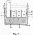
- Figures 14 and 15show an alternative embodiment 202 in which an internal side wall or liner 204 of desiccant material is formed within the exterior shell 182 and web 152 of the body 126 in a two-shot injection molding process.
- the construction materialcan be desiccant plastic, a traditional three phase polymer or a two phase polymer, for example.
- the linermay also be molded from a non-desiccated polymer such as polyethylene, polypropylene or other suitable materials.
- the thickness and height of the liner 204can be adjusted to provide tailored moisture protection to the vial or tailor the internal volume.
- the liner 204also provides stiffness to the vial which facilitates a moisture tight flip-top seal. By increasing or reducing the thickness or height of the liner walls, the sidewall deflection is adjusted to facilitate closure of the lid onto the vial body.
- the first platform 146is defined by desiccant material integral with the interior surface 140.
- An insert 206 made of desiccant materialis also provided.
- the insert 206defines the second platform 208 and the splines 162, 164, and 166, and substantially fills the entire region 156 of the dispenser as well as the portion of the reservoir 154 occupied by the splines 162, 164, and 166.
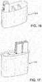
- Figures 16 and 17show alternative embodiments of inserts, respectively 210 and 212.
- Figure 18shows an alternative embodiment of a dispenser 214 in which the second platform 216 has a first portion 218 or 220 defining a first strip reservoir (respectively 222 or 224) and a second portion 226 non-coplanar with the first portion 218 or 220 and defining a second strip reservoir 228.
- the strip reservoirs 222 and 228have tops, respectively 230 and 232, at the same elevation and floors, respectively 234 and 236, at different elevations, so the second strip reservoir 228 is axially longer than the first strip reservoir 222.
- a strip reservoir 240is located beside the second platform 216, and extends down to and is defined by a portion 242 of the first platform 146.
- the strip reservoir 240is axially longer than the strip reservoirs 222, 224, and 228, and thus can accommodate even much longer strips 124 than the others.
- One optional advantage of the illustrated constructionis ease of access to the strips 122, 124. They are visible above the vial body rim or dispensing opening 126 when the lid 128 is open, and remain exposed above the dispensing opening 126 when the container is full, as well as after strips have been depleted. Yet, the test strips 122, 124 do not interfere with opening and closing the lid 128. Another advantage is that the strips remain standing upright and do not fall over into the sealing locations 136 and 138 when strips are removed.
- the illustrated constructionoptionally provides a longer shelf life for the strips 122, 124 by providing desiccants in various forms, as by two-shot molding of the body 126 to include a desiccant liner, molding internal components of the dispenser 120 from moldable desiccant thermoplastic materials, and including communicating chambers for containing loose or packaged desiccants.
- desiccantsin various forms, as by two-shot molding of the body 126 to include a desiccant liner, molding internal components of the dispenser 120 from moldable desiccant thermoplastic materials, and including communicating chambers for containing loose or packaged desiccants.
- One or more of these or other expedients for desiccating the dispenser 120can be used.
- FIG. 12 , 20 and 21Another aspect of the technology, illustrated by Figures 12 , 20 and 21 , is a method of making dispensers such as 120 for dispensing objects such as 124 of varying length.
- the methodallows one to customize a particular dispenser 120 to dispense objects such as 124 of a particular length, presenting the tops 250 of the objects such as 124 at an appropriate height in the dispenser 120.
- a first injection mold cavity 252is provided as shown in Figure 20 .
- the first mold cavity 252is adapted to form a generally tubular body such as the body 126 of Figure 12 .
- the body 126has a first platform 146, as previously described, that is formed in the cavity 252 by the projecting end 254 of the core 256, and which locates and supports the lower end 186 of the liner 184 when the dispenser 120 is assembled.
- a second injection mold cavity 260is provided as shown in Figure 21 .
- the second cavity 260is adapted to form an insert or liner 184, such a the liner 184 of Figure 5 , sized and configured to fit within the generally tubular body 126 of Figure 12 .
- the insert 184has a second platform 150, as shown in Figure 12 and described above, adapted to support objects such as 124.
- the second platformis formed by the leading edge 262 of a core 264.
- At least one of the first and second injection mold cavities 252 and 260is modified to place the first and second platforms 146 and 150 of the tubular body 126 and the insert 184 in relative axial positions adapted to support objects such as 124 of a specific length on the second platform 150 at a predetermined position relative to the dispensing opening 142.
- the position of the first platform 146 in the body 126can be raised by removing material from the core 256, so its new leading edge 266 is at the position shown in Figure 20 .
- the core 256can be replaced by a different core having a different length.
- Other expedients for accomplishing this customization stepare also well known to those skilled in the art.
- This modificationwill raise the level of the second platform of a dispenser assembled from the modified body 126 and the insert 184 as shown in Figure 12 .
- the position of the second platform 150 in the insert 184can be raised by removing material from the core 264, or by other expedients similar to those useful for the cavity 252, so the new leading edge 268 is at the position shown in Figure 21 .
- This modificationwill raise the level of the second platform 150 of a dispenser assembled from the body 126 as shown in Figure 12 and the insert 184 as thus modified.
- This methodallows one to customize the insert 184 to serially adapt for strips 124 of different lengths, presenting each at the ideal height for easy access without interfering with the lid 128.
- a variety of different inserts 184 having different dimensionscan be used with a particular body 126, depending on the particular strips 124 to be contained and dispensed.
- this methodallows one to customize the body 126 to serially adapt for strips 124 of different lengths, presenting each at the ideal height for easy access without interfering with the lid 128.
- a variety of different bodies 126 having different dimensionscan be used with a particular insert 184, depending on the particular strips 124 to be contained and dispensed.
- one strip reservoir such as 228 of the insert 184can be modified using this technique while another strip reservoir 222 retains its original dimensions or is modified to a different degree to suit a strip having a different length.
- another strip reservoir 222retains its original dimensions or is modified to a different degree to suit a strip having a different length.
- Figures 22 and 23illustrate that the strips can be oriented in various directions in the dispenser 120.
- the stripsare oriented so their major surfaces such as 268 and 270 face one of the longer sides of the dispenser 120.
- the test stripsare turned 90 degrees relative to the strips of Figure 22 , so the major surfaces such as 268 and 270 face one of the shorter sides of the dispenser 120.
- the dispenserhas perpendicular laterally extending first and second axes, and one or more strips of material in at least one of the reservoirs is oriented with its major faces substantially parallel to the first axis, or alternatively the second axis.
- Other orientationssuch as an oblique or diagonal orientation, are also contemplated.
- the followingis a suitable method of measuring moisture ingress for determining whether a vessel is waterproof as defined in this specification.
- the moisture ingress through the flip-top seal of the container of the present inventionis determined over a fifty (50) day period.
- a total of six (6) containersare used for the study.
- MSloose molecular sieve
- the test methodcan be described as follows: (a) placing two grams plus or minus 0.25 grams of molecular sieve ("MS") into four (4) containers and recording the weight; (b) recording the weight of two of the same containers which do not contain any MS material, which containers are maintained as controls; (c) closing the containers by applying, in a singular motion, a downward pressure upon the container lids or thumb tabs until the rim portions, adjacent to the thumb tabs, contact the inside flat part of the caps also adjacent to the thumb tabs; (d) weighing the six (6) containers and recording their respective weights; (e) placing the closed containers in an environmental chamber maintained at conditions of 80% relative humidity and 22.2°C; (f) weighing the containers on a daily basis for fifty (50) days, recording the weights of the respective containers, and returning them to the chamber; (g) subtracting the weights recorded in steps (a) and (b) from the current day weight of the respective containers to calculate the moisture ingress of the container in units of micrograms of water; and (h) determining the
- the "best result” numbersare the best single vial result of the several vials tested.
- test resultsshow a significant reduction in moisture ingress in the same vials, having the same sealing arrangements, with and without a reinforcement that reduces deflection of the sidewall along the minor axis.
Landscapes
- Engineering & Computer Science (AREA)
- Health & Medical Sciences (AREA)
- Chemical & Material Sciences (AREA)
- Biomedical Technology (AREA)
- Life Sciences & Earth Sciences (AREA)
- Physics & Mathematics (AREA)
- Mechanical Engineering (AREA)
- Food Science & Technology (AREA)
- General Health & Medical Sciences (AREA)
- Hematology (AREA)
- Analytical Chemistry (AREA)
- Biophysics (AREA)
- Clinical Laboratory Science (AREA)
- Medicinal Chemistry (AREA)
- Molecular Biology (AREA)
- Biochemistry (AREA)
- Optics & Photonics (AREA)
- General Physics & Mathematics (AREA)
- Immunology (AREA)
- Pathology (AREA)
- Urology & Nephrology (AREA)
- Chemical Kinetics & Catalysis (AREA)
- Packages (AREA)
- Closures For Containers (AREA)
- Medical Preparation Storing Or Oral Administration Devices (AREA)
- Details Of Rigid Or Semi-Rigid Containers (AREA)
- Closing Of Containers (AREA)
- Containers Having Bodies Formed In One Piece (AREA)
Abstract

Description
- This application claims the priority of
U.S. Ser. Nos. 61/053,277, filed May 15, 2008 61/081514, filed July 17, 2008 - The present disclosure relates to containers that can be used, for example, to house test strips, pills, capsules, particulate materials, liquids, or other objects or materials and control the ingress and/or egress of moisture. This patent application discloses technology related to that of
U.S. Ser. No. 29/318,272, filed May 16, 2008 - Cylindrical containers are described in the following patents as being "leak-proof:"
U.S. Patent Nos. 4,783,056 ,4,812,116 ,RE 37,676 and6,303,064 .U.S. Patents 6,769,558 and7,198,161 and European patent1 220 794 , all to the present inventor, disclose a leakproof, resealable cylindrical container and cap assembly. The disclosure of the processes of producing injection molded plastic containers and sealing them are incorporated by reference herein. - An aspect of the invention is a moisture proof, resealable non-cylindrical container and lid assembly. The term "resealable" means that the closure can be closed at least once after the container is opened for the first time. Preferably, the closure can be opened and closed additional times after the initial opening to remove all of the contents.
- The container has a body having an interior space, defined by a generally tubular sidewall. The body has a lid, and the lid and body have a non-round seal that is substantially moisture proof when the lid is seated on the body, meaning that when sealed the container admits less than 1000 micrograms per day of water determined by a moisture ingress test method. The container optionally is sized as a pharmaceutical package enclosing between 1 and 500 ml of interior volume, alternatively between 10 and 200 ml of interior volume, alternatively between 20 and 100 ml of internal volume.
- The body has a generally tubular sidewall with first and second axially opposed ends, a base, and a dispensing opening axially spaced from the base and at least adjacent to the second end. The interior space is disposed generally within the sidewall and at least generally between the base and the dispensing opening. The sidewall has a cross-section having a major diameter and a minor diameter, wherein the ratio between the major diameter and the minor diameter of the sidewall cross-section is a value between 1.1 : 1 and 10 : 1, inclusive.
- The container has a non-round body sealing surface located on the body and disposed about the dispensing opening, the body sealing surface having a major diameter and a minor diameter, wherein the ratio between the major diameter and the minor diameter of the body sealing surface is a value between 1.1 : 1 and 10 : 1, inclusive.
- The lid is configured to seat on the body. There is a lid sealing surface located on the lid. The body sealing surface and the lid sealing surface are configured to mate to form a seal between the lid and the body when the lid is seated on the body. The lid and lid sealing surface at least substantially close the dispensing opening and isolate the interior space from ambient conditions.
- An insert communicates with the interior space of the container and reinforces at least a portion of the body sealing surface against inward deflection along an axis defined by the minor diameter when the lid is seated on the body. The container has a moisture ingress rate of the container having a moisture ingress rate of 100-1000 micrograms per day, optionally 200-700 micrograms per day, optionally 380- 700 micrograms per day, optionally 400-700 micrograms per day, optionally 250- 400 micrograms per day, optionally less than 300 micrograms per day, at 80% relative humidity and 72 °F (22.2°C).
- Optionally, in any embodiment above, the interior space is defined at least in part by an interior surface made of a desiccant material.
- Optionally, in any embodiment above, the interior space is defined at least in part by a reinforcement stiffening the container against deflection along the minor axis.
- Optionally, in any embodiment above, the reinforcement is an insert assembled with the container.
- Optionally, in any embodiment above, the insert is secured to the container by an interference fit between the insert and the inner wall of the container
- Optionally, in any embodiment above, the insert is made of a desiccant material.
- Optionally, in any embodiment above, the insert is disposed within the container.
- Optionally, in any embodiment above, the insert is a liner generally following the inner wall of the container.
- Optionally, in any embodiment above, at least one of the ends of the container has an interior portion made of desiccant material.
- Optionally, in any embodiment above, the sidewall has an interior portion made of desiccant material.
- Optionally, in any embodiment above, the lid has an interior portion made of desiccant material.
- Optionally, in any embodiment above, at least a portion of the desiccant material is located in the interior space.
- Optionally, in any embodiment above, at least a portion of the desiccant is a particulate material.
- Optionally, in any embodiment above, at least a portion of the desiccant is provided in the form of one or more sachets.
- Optionally, in any embodiment above, at least a portion of the desiccant is provided in the form of one or more canisters.
- Optionally, in any embodiment above, at least a portion of the desiccant is provided in the form of one or more pellets.
- Optionally, in any embodiment above, the container further comprises a sleeve of desiccant material disposed within the body and at least partially defining the interior space.
- Optionally, in any embodiment above, the sleeve is integrally formed with at least one of the sidewall and an end wall.
- Optionally, in any embodiment above, the container further comprises a tether linking the container body and lid.
- Optionally, in any embodiment above, the tether comprises a hinge.
- Optionally, in any embodiment above, the tether comprises an integral hinge.
- Optionally, in any embodiment above, the hinge is configured to orient the lid to seat on the body when the lid and body are pivoted together.
- Optionally, in any embodiment above, the hinge defines a pivot axis that is generally perpendicular to the major axis.
- Optionally, in any embodiment above, the hinge defines a pivot axis that is generally parallel to the major axis.
- Optionally, in any embodiment above, the hinge extends from the sidewall at least adjacent to the end of the major axis.
- Optionally, in any embodiment above, the hinge extends from the sidewall at least adjacent to the end of the minor axis.
- Optionally, in any embodiment above, the body is at least generally oval in cross-section.
- Optionally, in any embodiment above, the body is at least generally polygonal in cross-section.
- Optionally, in any embodiment above, the body is at least generally rectangular in cross-section.
- Optionally, in any embodiment above, the body has at least one rounded corner.
- Optionally, in any embodiment above, at least a portion of the dispensing opening is defined by the second end of the sidewall.
- Optionally, in any embodiment above, the lid comprises a closed surface supporting the lid sealing surface.
- Optionally, in any embodiment above, the lid comprises a skirt surrounding and depending from the lid sealing surface.
- Optionally, in any embodiment above, the skirt is generally tubular.
- Optionally, in any embodiment above, the skirt cross-section is substantially congruent to the cross-section of the body sidewall, at least substantially defining an extension of the generally tubular sidewall when the lid is seated on the body.
- Optionally, in any embodiment above, the ratio between the major diameter and the minor diameter of the cross-section of the body sidewall is a value between 1.5 : 1 and 5 : 1, inclusive.
- Optionally, in any embodiment above, the ratio between the major diameter and the minor diameter of the cross-section of the sidewall is a value between 1.5 : 1 and 4 : 1, inclusive.
- Optionally, in any embodiment above, the ratio between the major diameter and the minor diameter of the cross-section of the sidewall is a value between 1.5 : 1 and 3 : 1, inclusive.
- Optionally, in any embodiment above, the ratio between the major diameter and the minor diameter of the cross-section of the sidewall is a value between 2 : 1 and 5 : 1, inclusive.
- Optionally, in any embodiment above, the ratio between the major diameter and the minor diameter of the cross-section of the sidewall is a value between 2 : 1 and 4:1, inclusive.
- Optionally, in any embodiment above, the ratio between the major diameter and the minor diameter of the cross-section of the sidewall is a value between 2 : 1 and 3 : 1, inclusive.
- Optionally, in any embodiment above, the ratio between the major diameter and the minor diameter of the cross-section of the body sidewall is a value between 1.5 : 1 and 5 : 1, inclusive.
- Optionally, in any embodiment above, the ratio between the major diameter and the minor diameter of the cross-section of the body sealing surface is a value between 1.5 : 1 and 4 : 1, inclusive.
- Optionally, in any embodiment above, the ratio between the major diameter and the minor diameter of the cross-section of the body sealing surface is a value between 1.5 : 1 and 3 : 1, inclusive.
- Optionally, in any embodiment above, the ratio between the major diameter and the minor diameter of the cross-section of the body sealing surface is a value between 2 : 1 and 5 : 1, inclusive.
- Optionally, in any embodiment above, the ratio between the major diameter and the minor diameter of the cross-section of the body sealing surface is a value between 2 : 1 and 4 : 1, inclusive.
- Optionally, in any embodiment above, the ratio between the major diameter and the minor diameter of the cross-section of the body sealing surface is a value between 2 : 1 and 3 : 1, inclusive.
- Optionally, in any embodiment above, at least a portion of the body and at least a portion of the lid are formed in one shot in an injection mold.
- Optionally, in any embodiment above, the body and the lid are formed in two shots in an injection mold.
- Optionally, in any embodiment above, the respective shots are a substantially moisture blocking polymeric material and a desiccant polymeric material.
- Another embodiment of the invention is a dispenser for strips of material, comprising a generally tubular body, a first platform, a second platform, and at least one spline. The body has an interior surface and first and second axially opposed ends, at least one of the ends defining a dispensing opening. The first platform extends laterally within the interior surface and positioned at the first end or between the first and second ends of the body. The second platform extends laterally within the interior surface, is positioned between and spaced axially from the first platform and the dispensing opening, and defines a reservoir between the second platform and the dispensing opening and a region between the first and second platforms. The spline extends axially and laterally within the reservoir and subdivides the reservoir into plural axially extending reservoirs communicating with the dispensing opening.
- Optionally, in any embodiment above, there is an open path of communication between the reservoir and at least one of the strip reservoirs.
- Optionally, in any embodiment above, there is an open path of communication between the reservoir and each of the strip reservoirs.
- Optionally, in any embodiment above, at least one open path of communication is a perforation in the second platform.
- Optionally, in any embodiment above, there is a desiccant material exposed to the reservoir.
- Optionally, in any embodiment above, the desiccant material is in contact with the region.
- Optionally, in any embodiment above, the region is defined by an interior surface composed at least in part of a desiccant material.
- Optionally, in any embodiment above, at least a portion of at least one of the body interior surface, a spline, the first platform, and the second platform is composed of a desiccant material.
- Optionally, in any embodiment above, at least a portion of the body interior surface is composed of a desiccant material.
- Optionally, in any embodiment above, at least a portion of at least one spline is composed of a desiccant material.
- Optionally, in any embodiment above, at least a portion of the first platform is composed of a desiccant material.
- Optionally, in any embodiment above, at least a portion of the second platform is composed of a desiccant material.
- Optionally, in any embodiment above, the body and at least one of the first platform, the second platform, and a spline are integral.
- Optionally, in any embodiment above, the body and the first platform are integral.
- Optionally, in any embodiment above, the body and the second platform are integral.
- Optionally, in any embodiment above, the body and a spline are integral.
- Optionally, in any embodiment above, the body and each spline are integral.
- Optionally, in any embodiment above, the body and each of the first platform, the second platform, and the splines are injection molded.
- Optionally, in any embodiment above, at least a portion of the body and at least a portion of the first platform are formed in one shot in an injection mold.
- Optionally, in any embodiment above, the second platform and splines are formed in one shot in an injection mold.
- Optionally, in any embodiment above, at least a portion of the body and the first platform are formed in a first shot in an injection mold and the second platform and splines are formed in a second shot in an injection mold.
- Optionally, in any embodiment above, the portions formed in the first shot define a first part, the portions formed in the second shot define a second part, and the first and second parts are joined together to define a dispenser.
- Optionally, in any embodiment above, there is a desiccant disposed in the region.
- Optionally, in any embodiment above, the desiccant is a particulate material.
- Optionally, in any embodiment above, the desiccant is provided in the form of one or more sachets, canisters, or pellets.
- Optionally, in any embodiment above, there is a cap for covering the dispensing opening.
- Optionally, in any embodiment above, there is a first seal surface on the cap and a second seal surface on the body, the seal surfaces being mateable to at least substantially seal the dispensing opening.
- Optionally, in any embodiment above, there is a hinge joining the dispenser body and cap.
- Optionally, in any embodiment above, there is a desiccant material disposed within the cap.
- Optionally, in any embodiment above, there is a sleeve of desiccant material disposed within the body and at least partially defining at least one of the reservoir and region.
- Optionally, in any embodiment above, the sleeve is integrally formed with at least one of the first and second platforms.
- Optionally, in any embodiment above, the second platform has a first portion defining a first strip reservoir.
- Optionally, in any embodiment above, the second platform further comprises a second portion non-coplanar with the first portion defining a second strip reservoir.
- Optionally, in any embodiment above, there is a second strip reservoir defined by a portion of the first platform.
- Optionally, in any embodiment above, the second strip reservoir is axially longer than the first strip reservoir.
- Optionally, in any embodiment above, the body is generally oval in cross-section.
- Optionally, in any embodiment above, the splines lie substantially parallel to the laterally extending long axis of the oval.
- Optionally, in any embodiment above, the splines lie substantially parallel to the laterally extending short axis of the oval.
- Optionally, in any embodiment above, there are perpendicular laterally extending first and second axes, further comprising one or more strips of material in at least one of the reservoirs oriented with their major faces substantially parallel to the first axis.
- Optionally, in any embodiment above, there are perpendicular laterally extending first and second axes, further comprising one or more strips of material in at least one of the reservoirs oriented with their major faces substantially parallel to the second axis.
- Another aspect of the invention is a method of making dispensers for objects of varying length to customize particular dispensers to dispense such objects of a particular length. The method is carried out in several steps.
- One step is providing a first injection mold cavity adapted to form a generally tubular body having an interior surface; first and second axially opposed ends, at least one of the ends defining a dispensing opening; and a first platform extending laterally within the interior surface and positioned between the axially opposed ends of the body.
- Another step is providing a second injection mold cavity adapted to form an insert sized and configured to fit within the generally tubular body, the insert having a second platform configured to be positioned between and spaced axially from the first platform and the dispensing opening when the insert is assembled with the body, defining a reservoir between the second platform and the dispensing opening and a region between the first and second platforms.
- A third step is modifying at least one of the first and second injection mold cavities to place the first and second platforms of the tubular body and the insert in relative axial positions adapted to support objects of a specific length on the second platform at a predetermined position relative to the dispensing opening.
- Optionally, in any embodiment above, the second injection mold cavity is modified.
- Optionally, in any embodiment above, the first injection mold cavity is not modified to customize the dispenser.
Figure 1 is a perspective view of an embodiment of a container, shown with the lid open.Figure 2 is a longitudinal section taken along section line 2-2 ofFigure 1 .Figure 3 is a cross-section taken along section line 3-3 ofFigure 1 .Figure 4 is an enlarged detail view of the hinge and lid sealing surface shown inFigure 2 , modified to show the lid seated on the body.Figure 5 is a cross-section similar toFigure 3 of another embodiment.Figure 6 is a cross-section similar toFigure 3 of yet another embodiment.Figure 7 is a cross-section of an additional embodiment of the invention.Figure 8 is a perspective view of an embodiment of the dispenser.Figure 9 is a side elevation of the embodiment ofFigure 8 .Figure 10 is a plan view of the embodiment ofFigure 8 .Figure 11 is a section of the embodiment ofFigure 8 taken along section lines 11-11.Figure 12 is a section of the embodiment ofFigure 8 taken along section lines 12-12.Figure 13 is a modification ofFigure 11 , showing as an alternative a false bottom defined by theweb 148 recessed in thebody 126.Figure 14 is a cutaway perspective view of another embodiment of the invention.Figure 15 is a sectional view of the embodiment ofFigure 14 .Figure 16 is a perspective view of a desiccant insert defining another embodiment of the dispenser.Figure 17 is a perspective view of another desiccant insert defining still another embodiment of the dispenser.Figure 18 is a view similar toFigure 15 showing other potential modifications to accommodate and uniformly present strips having different lengths.Figure 19 is a fragmentary plan view of an alternative embodiment in which the splines run perpendicular to their orientation shown inFigure 10 .Figure 20 is a schematic sectional view of a mold cavity for forming the body of a dispenser as shown inFigure 12 .Figure 21 is a schematic sectional view of a mold cavity for forming the insert of a dispenser as shown inFigure 12 .Figure 22 is a sectional view of an embodiment in which the faces or major surfaces of the strips face the longer side of the generally oval vial.Figure 23 is a sectional view of an embodiment in which the faces or major surfaces of the strips face the shorter side of the generally oval vial.- The following reference characters are used in the Figures.
Ref.Char. Description 10 Container 12 Body 14 Interior space 16 Body sealing surface 18 Lid 20 Lid sealing surface 22 Desiccant material 24 Generally tubular sidewall 26 First end (of 24) (base) 28 Second end (of 24) 30 Dispensing opening 32 Cross-section (of 24) 34 Major diameter (of 32) 36 Minor diameter (of 32) 38 Center (of 32) 40 Major diameter (of 16) 42 Minor diameter (of 16) 44 Body ( Figure 5 )46 Rounded corner (of 44) 47 Container ( Figure 6 )48 Closed surface (of 18) 50 Seal (of 16 and 20) 52 Skirt (of 18) 54 Integral hinge 56 Pivot axis (of 54) 58 Interior surface (of 24) 60 Interior portion of desiccant material 62 Interior portion (of 18) 64 Sachet 66 Canister 68 Pellet or particle 78 Inner seal 80 Container 82 Inner skirt 84 Seal gasket 86 Sealing surface 88 Contents 90 Lower end of 82 120 Dispenser 122 Strip of material 124 Strip of material 126 Generally tubular body 128 Lid 130 Hinge 132 Long axis (of 126) 134 Short axis (of 126) 136 Sealing location (of 126) 138 Sealing location (of 128) 140 Interior surface 142 First end (of 126) (disposing opening) 144 Second end (of 126) 146 First platform 148 Integrally forward web 150 Second platform 152 Web 154 Reservoir 156 Region 162 Spline 164 Spline 166 Spline 168 Strip reservoir 170 Strip reservoir 172 Strip reservoir 174 Strip reservoir 176 Platform perforations through 150, 152 178 Platform perforations through 150, 152 180 Platform perforations through 150, 152 182 Exterior shell (of 126) 184 Liner (of 126) 186 Lower end (of 184) 188 Interior surface (of 182) 190 Desiccant material (insert) 192 Desiccant material (in lid) 194 Perforation (in 150 and 152) 196 Desiccant sachet 198 Desiccant canister 200 Desiccant pellet 202 Embodiment ( Figs 14 and15 )204 Liner ( Figs 14 and15 )206 Insert ( Figs 14 and15 )208 Second platform ( Figs 14 and15 )210 Insert ( Figure 16 )212 Insert ( Figure 17 )214 Dispenser ( Figure 18 )216 Second platform ( Figure 18 )218 Portion (of 216) 220 Portion (of 216) 222 Compartment ( Figure 18 )224 Compartment ( Figure 18 )226 Second portion (of 216) 228 Second compartment ( Figure 18 )230 Top of 222 232 Top of 228 234 Body (of Figure 18 )240 Third compartment ( Figure 18 )250 Top (of 124) ( Figure 12 )252 First cavity 254 End (of 256) 256 Core 260 Second cavity 262 End (of 264) 264 Core 266 Trimmed leading edge (of 256) 268 Face of 122 270 Face of 124 U.S. Patents 6,769,558 and7,198,161 and European patent1 220 794 , all to the present inventor, disclose a leakproof, resealable, flip-top cylindrical container and cap assembly which comprises a cap and container attached by a hinge. A user is readily able to close the lid using the front tab on the lid. Those patents are incorporated here by reference for the characteristics and dimensions of a suitable seal for a container and cap assembly. When forming a moisture-tight seal using the flip-top closure described in the foregoing patents, the closure exerts a compressive force about the top of the container body. A sealing relationship is formed between the closure and the container body.- It is presently believed that the seal effectiveness, in large part, is due to the stiffness of the container walls. In an oval container (especially as the ratio between the major and minor axes becomes larger), the walls become less stiff against inward and outward deflection along the minor axis and are not able to withstand the force exerted by the closure. This lack of stiffness results in less seal integrity (i.e., a higher moisture ingress rate). In particular, the seal area of the sidewall of the container or cap is particularly subject to flexing along the minor axis, where the opposed walls have the largest radius in an oval container.
- The present inventor has further determined that this problem can be addressed by providing a reinforcement stiffening the container against deflection along the minor axis. The reinforcement can be extra material in the container wall itself, but can also be provided, for example by press-fitting or otherwise incorporating an insert or liner into the container to reinforce its portions at or near the beginning and end of the minor axis. The insert, which also has utility to orient test strips, may be used to stiffen the sidewalls of the container.
- Referring to
Figures 1 through 4 , a vial orcontainer 10 is shown including abody 12, aninterior space 14, abody sealing surface 16, alid 18, alid sealing surface 20, and adesiccant material 22 communicating with theinterior space 14. - The
body 12 can have a generallytubular sidewall 24 with first and second axially opposed ends 26 and 28 and a dispensingopening 30. The dispensingopening 30 is axially spaced from the first end orbase 26 and at least adjacent to thesecond end 28. In the embodiment ofFigures 1-4 , at least a portion of the dispensingopening 30 is defined by thesecond end 28 of thesidewall 24. - The
body 12 can have itsinterior space 14 disposed generally within thesidewall 24 and at least generally between the base 26 and the dispensingopening 30. The generallytubular sidewall 24 can have across-section 32, best shown inFigure 3 , having amajor diameter 34 and aminor diameter 36 each passing through thecenter 38. The ratio between themajor diameter 34 and theminor diameter 36 of thecross-section 32 can be, for example, a value between 1.1 : 1 and 10 : 1, inclusive. Alternatively, the ratio between themajor diameter 34 and theminor diameter 36 of thecross-section 32 of thebody sidewall 24 can be a value between 1.5 : 1 and 5 : 1, alternatively between 1.5 : 1 and 4 : 1, alternatively between 1.5 : 1 and 4 : 1, alternatively between 1.5 : 1 and 3 : 1, alternatively between 2 : 1 and 5 : 1, alternatively between 2 : 1 and 4 : 1, alternatively between 2 : 1 and 3 : 1, alternatively between 1.5 : 1 and 5 : 1, in each case the end points being inclusive. The upper and lower limits are not critical; the point of the ratios is to provide acontainer 10 that is wider than it is deep, or vice versa. - As illustrated in
Figures 1-4 , thebody 12 is at least generally oval incross-section 32. The body, however, can have other cross-sectional configurations. As illustrated inFigure 5 , the body 44 can be at least generally polygonal in cross-section, or at least generally rectangular in cross-section, and alternatively can have at least onerounded corner 46. Many other alternative configurations are also contemplated. For example, the container can be configured as shown in thecontainer 47 ofFigure 1 , with opposing concave and convex walls. - As illustrated in
Figures 1-4 , thebody sealing surface 16 is not round, is located on thebody 12, and is disposed about the dispensingopening 30. Thebody sealing surface 16 can have amajor diameter 40 and aminor diameter 42, and the ratio between themajor diameter 40 and theminor diameter 42 of thebody sealing surface 16 can be a value between 1.1 : 1 and 10 : 1, inclusive. Alternatively, the ratio between themajor diameter 40 and theminor diameter 42 of thebody sealing surface 16 can be between 1.5 : 1 and 4 : 1, alternatively between 1.5 : 1 and 3 : 1, alternatively between 1.5 : 1 and 2 : 1, alternatively between 2 : 1 and 5 : 1, alternatively between 2 : 1 and 4 : 1, alternatively between 2 : 1 and 3 : 1, in each case the end points being inclusive. The upper and lower limits again are not critical, and provide a non-round sealing surface. - It should be understood that the ratio of the major and
minor cross-section diameters minor diameters body sealing surface 16. Additionally, the shapes of thebody sealing surface 16 and thecross-section 32 can be the same or different. For example, thecross-section 32 could be rectangular with rounded corners and thebody sealing surface 16 could be elliptical. This is just one illustration of a possible alternative configuration. - The
lid 18 comprises aclosed surface 48 supporting thelid sealing surface 20. Thelid 18 can be configured to seat on thebody 12. It can have alid sealing surface 20. Thebody sealing surface 16 and thelid sealing surface 20 can be configured to mate to form a seal 50 (best seen inFigure 4 ) between thelid 18 and thebody 12 when thelid 18 is seated on thebody 12. When theseal 50 is formed, thelid 18 and theseal 50 defined by the sealing surfaces 16 and 20 at least substantially close the dispensingopening 30 and isolate theinterior space 14 from ambient conditions. - The
lid 18 ofFigures 1-4 can have a generallytubular skirt 52 surrounding and depending from thelid sealing surface 20. The cross-section of theskirt 52 can be substantially congruent to thecross-section 32 of the body sidewall, at least substantially defining an extension of the generallytubular sidewall 24 when thelid 18 is seated on thebody 12, as shown inFigure 4 . - In the illustrated embodiment of
Figures 1-4 , a tether, here configured as anintegral hinge 54, links thebody 12 and thelid 18. Thehinge 54 can be configured to orient thelid 18 to seat on thebody 12 when thelid 18 andbody 12 are pivoted together. The illustratedintegral hinge 54 ofFigures 1-4 , as illustrated, can extend from thesidewall 24 of thebody 12 at least adjacent to the end of theminor axis 42. The integral hinge as illustrated defines apivot axis 54 that can be generally parallel to themajor diameter 40. In an alternative embodiment, the integral hinge could be displaced 90 degrees circumferentially and extend from thesidewall 24 of thebody 12 at least adjacent to the end of themajor diameter 40. The integral hinge could then define a pivot axis that could be generally perpendicular to themajor axis 40. The integral hinge could also be displaced to an intermediate point between the ends of themajor diameter 40 andminor diameter 42, in another alternative embodiment, providing an oblique pivot axis parallel neither to themajor diameter 40 nor theminor diameter 42. - The inventors have found that a non-round seal, for example the
seal 50 shown inFigures 1-4 formed by mating the non-roundbody sealing surface 16 andlid sealing surface 20, does not exclude moisture as well as a round seal. Nonetheless, it may be necessary or useful to limit the amount of moisture entering or leaving theinterior space 14 of thecontainer 10, as when the contents of thecontainer 10 are moisture-sensitive. The inventors have found that the issue of moisture sensitivity caused by a non-round seal can be addressed and at least partially alleviated if thecontainer 10 includes a desiccant material such as 22 communicating with theinterior space 14 of thecontainer 10 when thelid 18 is seated on thebody 12. - An example of
suitable desiccant material 22 is the injection-moldable thermoplastic desiccant polymeric material described in one or more ofUS. Patent Nos. 5,911,937 ;6,214,255 ;6,130,263 ;6,080,350 ;6,174,952 ;6,124,006 ; and6,221,446 , all to Hekal. These patents are incorporated here by reference. Silica gel, a molecular sieve, calcium oxides or clay may also or instead be used directly as desiccants or incorporated into a desiccant material. The desiccant alternatively can be a material adapted to release a gas, such as an inert gas that prevents oxidation of the enclosed medicament, a flavoring or fragrance, or moisture, in the case of a medicament that should not be allowed to dry out. - For example, in the
container 10 ofFigures 1-4 , theinterior space 14 can be defined at least in part by aninterior surface 58 of thebody 12 made of adesiccant material 22. In thecontainer 10 ofFigures 1-4 , at least one of the ends of thecontainer 10, here thefirst end 26, also can have aninterior portion 60 made of desiccant material. Additionally or alternatively, thelid 18 can have aninterior portion 48 that can be integrally molded ofdesiccant material 22. Additionally or alternatively, theinterior surface 58 ofdesiccant 22 can be defined by a separately molded sleeve ofdesiccant material 22 placed within thebody 12 and at least partially defining theinterior space 14. The sleeve can be integrally formed with at least one of the sidewall and an end wall. - In an alternative or additional embodiment, also illustrated in
Figure 2 , at least a portion of thedesiccant material 22 can located in theinterior space 14. For example, as shown inFigure 2 , at least a portion of thedesiccant 22 can be provided in the form of one ormore sachets 64, orcanisters 66, or aparticulate material 68, which can be provided as pellets or in other particulate forms. - Referring now to
Figure 7 , a secondary seal generally indicated at 78 is disclosed for acontainer 80 otherwise similar to that ofFigures 1-4 . InFigure 7 , thelid 18 has aninner skirt 82 and thebody 12 contains adesiccant insert 22 and a generallyannular seal gasket 84 having a sealingsurface 86 encircling thecontents 88 of the container. Theinner skirt 82 has a distal orlower end 90 bearing against theseal gasket 84, forming the seal. Theseal gasket 84 can be made of an elastomeric material (for example a thermoplastic elastomer, TPE.) One contemplated TPE is Santoprene®, which is a registered trademark of Monsanto Company of St. Louis, Missouri, U.S.A. - The position of the
lower end 90 of theweb 82, and thus theseal 78, can be closer to theouter skirt 52 of the lid than illustrated inFigure 7 , which may be useful to allow more space within theinner seal 80. Thegasket 86 can alternatively be reduced to just the portion beneath thelower end 90 of theinner skirt 82, although an advantage of the illustrated embodiment is that the material of theseal gasket 84 can also isolate the top surface of thedesiccant material 22 from direct contact with the environment when thecontainer 80 is opened. - In any embodiment an elastomer may also be located along the top interior surface of the
vial body 12, such as thebody sealing surface 16, to resiliently seat against thelid sealing surface 20. - A secondary sealing element can also or alternatively be formed along the inside surface of the flip-
top lid 18. The secondary sealing element may be located in close proximity to the sidewall orskirt 52 of the flip-top lid 18. When thelid 18 is closed, the secondary sealing element compresses the elastomer along the top surface of the insert to form a secondary seal, in combination with the seal according toU.S. Patent 6,769,558 and other patents as previously described. - More generally, any one or more of the desiccant or sealing features shown in the Figures can be used individually or together, and additional embodiments deploying the desiccant or sealing elements in other ways are also contemplated.
- The
container 10 can be made in various ways. In one embodiment, thecontainer 10 and itsdesiccant feature 22 can each be separately injection molded from thermoplastic material, as in a one-shot or two-shot injection process, then assembled. The first mold is used to produce the flip-top vial lid 18 andintegral hinge 54 can be integrally formed in the same mold as theouter body 12. In one embodiment, the flip-top vial lid is closed in the mold. - Alternatively, the
body 12 and thedesiccant polymeric material 22 can formed in two shots in one injection mold. - In the embodiment of
Figure 7 , the insert is composed of two materials: adesiccant plastic 22 and anelastomeric material 84. Theinsert 22 andseal gasket 84 may be molded in a 2-shot injection molding process. Thedesiccant material 22 of the insert is formed in the first shot. Next, theelastomeric material 84 is formed in the second shot. The composite insert is assembled into the vial. Alternatively, the seal material and the material of thebody 12 orlid 18 can be formed in a single, two-shot mold. - One of many known examples of suitable material for the outer portions of the
container 10 can be polypropylene - a moisture blocking polymeric material. For example, theouter body 12 andlid 18 can be made of polypropylene, and the desiccant features such theinterior portion 60 can be made of a desiccant material. - The container can also be made as disclosed in any of the embodiments of
U.S. Ser. No. 61/053,277 29/318,272 - When the insert is assembled into the vial, the
elastomeric material 84 forms a secondary seal along the top interior surface of the vial flip-top lid. - Referring more particularly to
Figures 8-10 , the illustrateddispenser 120 is a vial including a generallytubular body 126 and alid 128 joined together by ahinge 130. In this embodiment thebody 126 is generally oval or elliptical in cross-section, having a laterally extending long axis 132 (running from top to bottom inFigure 10 ) and a laterally extending short axis 134 (running from side to side inFigure 10 ). Optionally, thebody 126,lid 128, and hinge 130 can be integrally formed, as by molding the assembly in a one-shot injection mold to form thebody 126, thelid 128, and anintegral hinge 130 simultaneously. Thebody 126,lid 128, and hinge 130 can be made of any suitable material, commonly a substantially moisture-impervious material and commonly a thermoplastic material that is useful for injection molding. Thebody 126,lid 128, and thehinge 130 can be made of polypropylene or polyethylene, for example, to provide good moisture protection. - The
lid 128 andbody 126 respectively have first andsecond sealing locations lid 128 is seated on thebody 126 to at least substantially seal thedispensing opening 142 and minimize contact of water vapor or other environmental substances with the test strips such as 122 and 124 or other contents of thedispenser 120. Thebody 126 has aninterior surface 140 and first and second axially opposed ends 142 and 144, and at least one of the ends, here theend 142, defines a dispensing opening. Figures 10-12 in particular show various interior details of the embodiment ofFigure 8 .- The
body 126 has afirst platform 146, in this embodiment defined by the upper surface of an integrally formedweb 148. (Words of orientation such as "upper," "lower" or "lateral" in this specification refer to thedispenser 120 when it is oriented as shown inFigures 11-12 . "Axial" is up or down as shown inFigures 11 and12 , and "lateral" refers to any direction having a component perpendicular to axial For example, a direction perpendicular to axial and a direction forming an angle of 45 degrees with respect to axial are both lateral directions.) Thefirst platform 146 extends laterally within theinterior surface 140 and is positioned at least substantially at the end 44 of the body. - The
body 126 has asecond platform 150 extending laterally within theinterior surface 140. Thesecond platform 150 is positioned between and spaced axially from thefirst platform 146 and thedispensing opening 142. In the embodiment ofFigures 8-12 , thesecond platform 150 is defined by the upper surface of a laterally extendingweb 152. - The
second platform 150 is positioned and configured to provide adequate elevation to extend thetest strips opening 142 of thevial body 126 and position them within the lid 128 (when closed) without damaging the exposed ends of the test strips. Damage could occur when the lid is closed and strips such as 122, 124 lean or bend over and get trapped between thevial body 126 and thelid 128. - By extending the
test strips opening 142 of the vial body, the end user will have substantially easier access to thetest strips vial lid 128 is open. Since commercial test strips have many different lengths, thesecond platform 150 of thedispenser 120 can be easily adjusted to the test strip length to consistently be able to provide a package that presents the test strips to the consumer uniformly, regardless of the test strip length, without necessarily changing the overall length of the generallytubular body 126. - Additionally, the first and
second platforms oval dispenser 120 than on a round dispenser. The platforms allow additional desiccant to be added to thedispenser 120 for enhanced shelf life protection. Oval vials also are more difficult to manufacture due to the difference in shrinkage of the primarily flat sides as opposed to the sharper corners on the ends. This non-uniform geometry causes differences in shrinkage rates compared to a round vial. - A reservoir generally indicated at 154 is located between the
second platform 150 and thedispensing opening 142, and a region generally indicated at 156 is located between the first andsecond platforms partition 162, and in the embodiment ofFigures 8-12 threeparallel splines reservoir 154 and subdivide the reservoir into plural axially extending compartments or strip reservoirs, such as 168, 170, 172, and 174, communicating with the dispensingopening 142. In this embodiment, thesplines short axis 134 of the oval. In an alternative embodiment, as illustrated inFigure 19 , the splines such as 167 and 169 could lie substantially parallel to the laterally extendinglong axis 132 of the oval. - Partitioning the
reservoir 154 usingsplines test strips splines body 126 and insert 190, thesplines test strips locations test strips locations lid 128. - The
dispenser 120 can have an open path of communication, such as theplatform perforations second platform 150 andweb 152, between thereservoir 154 and at least one of the strip reservoirs, such as 168. In the embodiment ofFigures 8-12 , an open path of communication is provided between thereservoir 154 and each of thestrip reservoirs - In the dispenser, the
body 126 and at least one of thefirst platform 146, thesecond platform 150, and a spline such as 162, 164, 166, and 168 are integral. In the dispenser ofFigures 8-12 , for example, the body and the first platform are integral. - In the embodiment of
Figures 8-12 , with particular reference toFigures 11 and12 , thebody 126 includes anexterior shell 182, which can be made of moisture-impervious material integrally formed with thefirst platform 146 andweb 148. In the dispenser ofFigures 8-12 , at least a portion of the body and at least a portion of the first platform are formed in one shot in an injection mold, forming a first part. - A generally
tubular liner 184 is provided, here including thesecond platform 150 and thesplines second platform 150 and thesplines dispenser 120. - The
liner 184 of the embodiment shown inFigures 8-12 has alower end 186 that, in the illustrated embodiment, abuts thefirst platform 146 to locate theliner 184 precisely within thebody 126. The axial distance between thesecond platform 150 and thedispensing opening 142 can be selected by providing alower end 186 that is spaced a corresponding distance from thesecond platform 150. This allows thedispenser 120 to be customized forstrips 122 of a particular length without changing the mold used to form theexterior shell 182. - By providing an assembly of a separately molded
liner 184 andshell 182, each of these parts can be made, in whole or in part, in a one-shot injection mold, without the need for side draws or other complicated and expensive molding or machining techniques that would otherwise be needed to make such an extensively undercut part. In the embodiment ofFigures 8-12 , thebody 126 and each of thefirst platform 146, thesecond platform 150, and thesplines - A desiccant optionally can be incorporated into the
dispenser 120 to keep the partial pressure of water vapor within thedispenser 120 relatively low compared to ambient conditions. One objective can be to reduce the partial pressure of water vapor in thereservoir 154 where the strips such as 122 and 124 are stored. A desiccant can be provided anywhere within the enclosure formed by theexterior shell 182, including but not limited to on aninterior surface 188 of theshell 182 itself. - For example, the
shell 182 could be partially or entirely molded from an injection moldable desiccant composition. Suitable desiccant plastics include, but are not limited to, those disclosed inUS. Patent Nos. 5,911,937 ;6,214,255 ;6,130,263 ;6,080,350 ;6,174,952 ;6,124,006 ; and6,221,446 , all to Hekal. These disclosures of these patents are incorporated herein by reference. Silica gel, a molecular sieve, calcium oxides or clay may be used directly as desiccants or incorporated into a desiccant material. The desiccant can also or instead be a material adapted to release a gas, such as an inert gas that prevents oxidation of the enclosed medicament, a flavoring or fragrance, or moisture, in the case of a medicament that should not be allowed to dry out. - The
reservoir 154 can be desiccated, for example, by providing a desiccant material such as 190 that is exposed to thereservoir 154. "Exposed" as used here is a broad term including direct contact between the desiccant and the reservoir to be desiccated, as well as communication between thedesiccant 190 and thereservoir 154, optionally via a passage or series of passages lying between the desiccant such as 190 and thereservoir 154. - For example, with reference to
Figure 12 , adesiccant material 192 provided in thelid 128 is exposed to thedesiccant region 156. Adesiccant material 190 is also exposed to thereservoir 154, in this instance via theregion 156 and theplatform perforation 194. Theplatform perforation 194 communicates between theregion 156 and thereservoir 154. With reference toFigure 11 , the desiccant packet orsachet 196, thedesiccant canister 198, and thedesiccant pellet 200 are also each exposed to thereservoir 154. Figure 11 also illustrates adispenser 120 in which thedesiccant materials region 156. As used here, "contact" has a more specific definition that requires the desiccant to be within or adjacent to theregion 156.- The dispenser can have at least a portion of any one of the body
interior surface 188, a spline such as 162, 164, or 166, thefirst platform 146, or thesecond platform 156, or any combination of these parts, composed of a desiccant material. - The
dispenser 120 can also include a desiccant such as one ormore sachets 196,canisters 198, orpellets 200 disposed in theregion 156. "Disposed in" is a more particular term meaning that the desiccant is located within the boundaries of theregion 156. One advantage of the embodiment ofFigures 8-12 is that it provides a considerable amount of space in theregion 156 to place one or more sachets such as 196 or canisters such as 198 containing particulate material, or free pellets or particulate material such as 200 containing or made of desiccant material. Theregion 156 thus can provide a desiccant reservoir at least somewhat isolated from thereservoir 154. In an embodiment, theregion 156 can be sized to contain a suitable amount of desiccant of any type or form to maintain a low water vapor pressure in thereservoir 154. - The
sleeve 184 of desiccant material disposed within thebody 126 can at least partially define at least one of thereservoir 154 and theregion 156. In the embodiment ofFigures 8-12 , the sleeve partially defines each of thereservoir 154 and theregion 156. Figure 13 shows an alternative embodiment, compared toFigure 11 , in which thedispenser 120 has a false bottom defined by theweb 148. In this embodiment, thefirst platform 146 is located between the axially opposed ends 142 and 144 of the body. In this embodiment, thefirst platform 150 can be positioned between theends test strips opening 142 of thevial body 126 and position them within the lid 128 (when closed) without damaging the exposed ends of the test strips. The position of thefirst platform 146 thus can be adjusted along with or independently of the position of thesecond platform 150 to adjust the positions of the tops of the test strips such as 122 and 124 in thecontainer 120.Figures 14 and15 show analternative embodiment 202 in which an internal side wall orliner 204 of desiccant material is formed within theexterior shell 182 andweb 152 of thebody 126 in a two-shot injection molding process. The construction material can be desiccant plastic, a traditional three phase polymer or a two phase polymer, for example. The liner may also be molded from a non-desiccated polymer such as polyethylene, polypropylene or other suitable materials.- The thickness and height of the
liner 204 can be adjusted to provide tailored moisture protection to the vial or tailor the internal volume. Theliner 204 also provides stiffness to the vial which facilitates a moisture tight flip-top seal. By increasing or reducing the thickness or height of the liner walls, the sidewall deflection is adjusted to facilitate closure of the lid onto the vial body. - In this embodiment, the
first platform 146 is defined by desiccant material integral with theinterior surface 140. Aninsert 206 made of desiccant material is also provided. Theinsert 206 defines thesecond platform 208 and thesplines entire region 156 of the dispenser as well as the portion of thereservoir 154 occupied by thesplines Figures 16 and 17 show alternative embodiments of inserts, respectively 210 and 212.Figure 18 shows an alternative embodiment of adispenser 214 in which thesecond platform 216 has afirst portion second portion 226 non-coplanar with thefirst portion second strip reservoir 228. Thestrip reservoirs second strip reservoir 228 is axially longer than thefirst strip reservoir 222.- Also in
Figure 18 , astrip reservoir 240 is located beside thesecond platform 216, and extends down to and is defined by aportion 242 of thefirst platform 146. Thestrip reservoir 240 is axially longer than thestrip reservoirs - One optional advantage of the illustrated construction is ease of access to the
strips opening 126 when thelid 128 is open, and remain exposed above the dispensingopening 126 when the container is full, as well as after strips have been depleted. Yet, thetest strips lid 128. Another advantage is that the strips remain standing upright and do not fall over into the sealinglocations - The illustrated construction optionally provides a longer shelf life for the
strips body 126 to include a desiccant liner, molding internal components of thedispenser 120 from moldable desiccant thermoplastic materials, and including communicating chambers for containing loose or packaged desiccants. One or more of these or other expedients for desiccating thedispenser 120 can be used. - Another aspect of the technology, illustrated by
Figures 12 ,20 and 21 , is a method of making dispensers such as 120 for dispensing objects such as 124 of varying length. The method allows one to customize aparticular dispenser 120 to dispense objects such as 124 of a particular length, presenting thetops 250 of the objects such as 124 at an appropriate height in thedispenser 120. - To carry out the method, a first
injection mold cavity 252 is provided as shown inFigure 20 . Thefirst mold cavity 252 is adapted to form a generally tubular body such as thebody 126 ofFigure 12 . Thebody 126 has afirst platform 146, as previously described, that is formed in thecavity 252 by the projectingend 254 of thecore 256, and which locates and supports thelower end 186 of theliner 184 when thedispenser 120 is assembled. - A second
injection mold cavity 260 is provided as shown inFigure 21 . Thesecond cavity 260 is adapted to form an insert orliner 184, such a theliner 184 ofFigure 5 , sized and configured to fit within the generallytubular body 126 ofFigure 12 . Theinsert 184 has asecond platform 150, as shown inFigure 12 and described above, adapted to support objects such as 124. The second platform is formed by theleading edge 262 of acore 264. - To customize the
dispenser 120, at least one of the first and secondinjection mold cavities second platforms tubular body 126 and theinsert 184 in relative axial positions adapted to support objects such as 124 of a specific length on thesecond platform 150 at a predetermined position relative to thedispensing opening 142. - For example, the position of the
first platform 146 in thebody 126 can be raised by removing material from thecore 256, so its newleading edge 266 is at the position shown inFigure 20 . Alternatively, thecore 256 can be replaced by a different core having a different length. Other expedients for accomplishing this customization step are also well known to those skilled in the art. This modification will raise the level of the second platform of a dispenser assembled from the modifiedbody 126 and theinsert 184 as shown inFigure 12 . - For another example, the position of the
second platform 150 in theinsert 184 can be raised by removing material from thecore 264, or by other expedients similar to those useful for thecavity 252, so the newleading edge 268 is at the position shown inFigure 21 . This modification will raise the level of thesecond platform 150 of a dispenser assembled from thebody 126 as shown inFigure 12 and theinsert 184 as thus modified. - Further, both of these modifications could be made at the same time, or either one could be used without using the other.
- Of course, the opposite modification could be made in either or both cases to lower the position of the
second platform 150. - This method allows one to customize the
insert 184 to serially adapt forstrips 124 of different lengths, presenting each at the ideal height for easy access without interfering with thelid 128. Thus, a variety ofdifferent inserts 184 having different dimensions can be used with aparticular body 126, depending on theparticular strips 124 to be contained and dispensed. Conversely, this method allows one to customize thebody 126 to serially adapt forstrips 124 of different lengths, presenting each at the ideal height for easy access without interfering with thelid 128. Thus, a variety ofdifferent bodies 126 having different dimensions can be used with aparticular insert 184, depending on theparticular strips 124 to be contained and dispensed. - It will be understood as well, with reference to
Figure 18 , that one strip reservoir such as 228 of theinsert 184 can be modified using this technique while anotherstrip reservoir 222 retains its original dimensions or is modified to a different degree to suit a strip having a different length. Thus, a very simple and versatile way to customizedispensers 126 for a wide variety of different strips such as 124 has been illustrated. Figures 22 and 23 illustrate that the strips can be oriented in various directions in thedispenser 120. InFigure 22 , the strips are oriented so their major surfaces such as 268 and 270 face one of the longer sides of thedispenser 120. InFigure 23 , the test strips are turned 90 degrees relative to the strips ofFigure 22 , so the major surfaces such as 268 and 270 face one of the shorter sides of thedispenser 120. In other words, the dispenser has perpendicular laterally extending first and second axes, and one or more strips of material in at least one of the reservoirs is oriented with its major faces substantially parallel to the first axis, or alternatively the second axis. Other orientations, such as an oblique or diagonal orientation, are also contemplated.- The following is a suitable method of measuring moisture ingress for determining whether a vessel is waterproof as defined in this specification.
- The moisture ingress through the flip-top seal of the container of the present invention is determined over a fifty (50) day period. A total of six (6) containers are used for the study. Two containers, referred to as CONTROL A and CONTROL B, do not contain desiccant. Four other containers, referred to as Samples C, D, E, F, have 2.0 grams of loose molecular sieve (MS) powder placed inside, plus or minus 0.25 grams. The dimensions of the containers are approximately 26.75 mm thick x 43.70 mm wide x 50.25 mm tall.
- The test method can be described as follows: (a) placing two grams plus or minus 0.25 grams of molecular sieve ("MS") into four (4) containers and recording the weight; (b) recording the weight of two of the same containers which do not contain any MS material, which containers are maintained as controls; (c) closing the containers by applying, in a singular motion, a downward pressure upon the container lids or thumb tabs until the rim portions, adjacent to the thumb tabs, contact the inside flat part of the caps also adjacent to the thumb tabs; (d) weighing the six (6) containers and recording their respective weights; (e) placing the closed containers in an environmental chamber maintained at conditions of 80% relative humidity and 22.2°C; (f) weighing the containers on a daily basis for fifty (50) days, recording the weights of the respective containers, and returning them to the chamber; (g) subtracting the weights recorded in steps (a) and (b) from the current day weight of the respective containers to calculate the moisture ingress of the container in units of micrograms of water; and (h) determining the moisture ingress through the seal by discounting the moisture ingress through the vial, according to the following methodology, calculated on a daily basis:
- N is Sample Type (A - F)
- Sn is Sample Weight Gain = (Current Vial Weight minus Initial Vial Weight at Start of Study)
- Ctrl is Average Weight Gain of Control Samples = (SA+SB)/2
- TS is Average Weight Gain of Test Samples = (SC+SD+SE+SF)/4
- MI is Moisture Ingress through Seal = (TS - Ctrl).
- Two different groups of oval-section vials with lids, respectively formed in Mold Cavity A and Mold Cavity B, and press-in tubular inserts for each type of vial similar to the inserts forming the
surface 58 inFigure 2 were provided. The tubular inserts were found to reinforce the vials against deflection of the body wall along the minor axis. - The moisture ingress test was run on a group of the vials without an insert, and also on a group of the same types of vials with inserts. The following results were obtained:
µg H2O per day Vial Vial with insert Mold Cavity A Best result 600 400 Mean Ingress 716 466 Std Dev 90 54 Mold Cavity B Best result 500 380 Mean Ingress 694 419 Std Dev 116 39 - In the above test results, the "best result" numbers are the best single vial result of the several vials tested.
- The test results show a significant reduction in moisture ingress in the same vials, having the same sealing arrangements, with and without a reinforcement that reduces deflection of the sidewall along the minor axis.
- Certain embodiments of the invention have been described in detail in this specification and illustrated by the drawing figures. This invention is not limited, however, to the specific embodiments and features described in the specification. The invention extends to the full scope of the claims as initially or later presented in this specification.
- 1. A moisture-tight, re-sealable container comprising:
- a. a body having a generally tubular sidewall with first and second axially opposed ends, a base, and a dispensing opening axially spaced from the base and at least adjacent to the second end;
- b. an interior space disposed generally within the sidewall and at least generally between the base and the dispensing opening;
- c. the generally tubular sidewall having a cross-section having a major diameter and a minor diameter, wherein the ratio between the major diameter and the minor diameter of the sidewall cross-section is a value between 1.1 : 1 and 10 : 1, inclusive;
- d. a non-round body sealing surface located on the body and disposed about the dispensing opening, the body sealing surface having a major diameter and a minor diameter, wherein the ratio between the major diameter and the minor diameter of the body sealing surface is a value between 1.1 : 1 and 10 : 1, inclusive;
- e. a lid configured to seat on the body;
- f. a lid sealing surface located on the lid;
- g. the body sealing surface and the lid sealing surface being configured to mate to form a seal between the lid and the body when the lid is seated on the body;
- h. the lid and lid sealing surface at least substantially closing the dispensing opening and isolating the interior space from ambient conditions; and
- i. an insert communicating with the interior space of the container and reinforcing at least a portion of the body sealing surface against inward deflection along an axis defined by the minor diameter when the lid is seated on the body;
- 2. The container of aspect 1, in which the interior space is defined at least in part by an interior surface made of a desiccant material.
- 3. The container of aspect 1, in which the interior space is defined at least in part by a reinforcement stiffening the container against deflection along the minor axis.
- 4. The container of
aspect 3, in which the reinforcement is an insert assembled with the container. - 5. The container of aspect 4, in which the insert is secured to the container by an interference fit between the insert and the inner wall of the container
- 6. The container of aspect 4, in which the insert is made of a desiccant material.
- 7. The container of aspect 4, in which the insert is disposed within the container.
- 8. The container of aspect 4, in which the insert is a liner generally following the inner wall of the container.
- 9. The container of any preceding aspect, in which the body is at least generally oval in cross-section.
- 10. The container of any preceding aspect, wherein the ratio between the major diameter and the minor diameter of the cross-section of the sidewall is a value between 1.5 : 1 and 3 : 1, inclusive.
- 11. The container of any preceding aspect, wherein the ratio between the major diameter and the minor diameter of the cross-section of the body sealing surface is a value between 1.5 : 1 and 3 : 1, inclusive.
- 12. A dispenser for strips of material, comprising:
- a generally tubular body having an interior surface and first and second axially opposed ends, at least one of the ends defining a dispensing opening;
- a first platform extending laterally within the interior surface and positioned at the first end or between the first and second ends of the body;
- a second platform extending laterally within the interior surface, positioned between and spaced axially from the first platform and the dispensing opening, and defining a reservoir between the second platform and the dispensing opening and a region between the first and second platforms;
- at least one spline extending axially and laterally within the reservoir and subdividing the reservoir into plural axially extending reservoirs communicating with the dispensing opening.
- 13. A method of making dispensers for objects of varying length to customize particular dispensers to dispense such objects of a particular length, the method comprising:
- providing a first injection mold cavity adapted to form a generally tubular body having an interior surface; first and second axially opposed ends, at least one of the ends defining a dispensing opening; and a first platform extending laterally within the interior surface and positioned between the axially opposed ends of the body;
- providing a second injection mold cavity adapted to form an insert sized and configured to fit within the generally tubular body, the insert having a second platform configured to be positioned between and spaced axially from the first platform and the dispensing opening when the insert is assembled with the body, defining a reservoir between the second platform and the dispensing opening and a region between the first and second platforms;
- modifying at least one of the first and second injection mold cavities to place the first and second platforms of the tubular body and the insert in relative axial positions adapted to support objects of a specific length on the second platform at a predetermined position relative to the dispensing opening.
Claims (19)
- A moisture-tight, re-sealable container comprising:a. a body that is generally elliptical in cross-section having a generally tubular sidewall with first and second axially opposed ends, a base, and a dispensing opening axially spaced from the base and adjacent to the second end;b. an interior space disposed generally within the sidewall and at least generally between the base and the dispensing opening;c. the generally tubular sidewall having a generally elliptical cross-section;d. a generally elliptical body sealing surface located on an exterior portion of the body and disposed about the dispensing opening;e. a lid configured to seat on the body, the lid being linked to the body by a hinge;f. a lid sealing surface located on an interior portion of the lid;g. the body sealing surface and the lid sealing surface being configured to mate to form a seal between the lid and the body when the lid is seated on the body; andh. the lid and lid sealing surface at least substantially closing the dispensing opening and isolating the interior space from ambient conditions, wherein the container is configured to store strips of material, optionally test strips, such that exposed ends of the strips of material extend beyond the dispensing opening of the body and wherein the exposed ends are positioned within the lid when the lid is seated on the body without damaging the exposed ends;the container having a moisture ingress rate of 100-1000 micrograms per day, at 80% relative humidity and 22.2°C.
- The container of claim 1, further comprising a non-round body sealing surface located on the body and disposed about the dispensing opening, the body sealing surface having a major diameter and a minor diameter, wherein the ratio between the major diameter and the minor diameter of the body sealing surface is a value between 1.1 : 1 and 10 : 1, inclusive.
- The container of claim 2, further comprising an insert communicating with the interior space of the container and reinforcing at least a portion of the body sealing surface against inward deflection along an axis defined by the minor diameter when the lid is seated on the body.
- The container of any of the preceding claims, wherein the lid comprises a lid sidewall extending from the lid sealing surface and terminating at a lid underside.
- The container of any of the preceding claims, wherein the container is configured to store strips of material, optionally test strips, such that exposed ends of the strips of material extend beyond the entire dispensing opening of the body and wherein the exposed ends are positioned within the lid when the lid is seated on the body without damaging the exposed ends.
- The container of any previous claim, further comprising a reinforcement stiffening the body sealing surface against deflection when the lid is seated on the body.
- The container of claim 6, wherein the reinforcement is defined at least in part by an insert assembled within the container.
- The container of claims 6 or 7, wherein the reinforcement is defined at least in part by an interior surface comprising an injection-moldable thermoplastic desiccant polymeric material.
- The container of any previous claim, wherein the generally elliptical cross-section of the generally tubular sidewall and the body sealing surface each have a major diameter and a minor diameter, wherein the ratio between the major diameter and the minor diameter of the sidewall cross-section and the body sealing surface respectively, is a value between 1.1 : 1 and 10 : 1, inclusive.
- The container of any previous claim, the lid having a generally tubular skirt surrounding and depending from the lid sealing surface, wherein the skirt cross-section is substantially congruent to the cross-section of the body sidewall, substantially defining an extension of the generally tubular sidewall when the lid is seated on the body.
- The container of any previous claim, having a plurality of test strips disposed therein and oriented vertically, wherein exposed ends of the test strips extend beyond the dispensing opening when the lid is seated on the body, wherein the exposed ends are positioned within the lid.
- A method for storing test strips in a container, the method comprising the steps of:a. providing a moisture-tight, resealable container comprising:i. a body that is generally elliptical in cross-section having a generally tubular sidewall with first and second axially opposed ends, a base, and a dispensing opening axially spaced from the base and adjacent to the second end;ii. an interior space disposed generally within the sidewall and at least generally between the base and the dispensing opening;iii. the generally tubular sidewall having a generally elliptical cross-section;iv. a generally elliptical body sealing surface located on an exterior portion of the body and disposed about the dispensing opening;v. a lid configured to seat on the body, the lid being linked to the body by a hinge;vi. a lid sealing surface located on an interior portion of the lid, the lid having a lid underside that is axially spaced from the lid sealing surface and from the dispensing opening when the lid is seated on the body;vii. the body sealing surface and the lid sealing surface being configured to mate to form a seal between the lid and the body when the lid is seated on the body; andviii. the lid and lid sealing surface at least substantially closing the dispensing opening and isolating the interior space from ambient conditions, wherein the container has a moisture ingress rate of 100-1000 micrograms per day, at 80% relative humidity and 22.2°C ; andb. disposing a plurality of test strips in the body of the container, the plurality of test strips being oriented such that exposed ends of the test strips extend beyond the dispensing opening when the lid is seated on the body, wherein the exposed ends are positioned within the lid.
- The method according to claim 12, wherein the container further comprises a non-round body sealing surface located on the body and disposed about the dispensing opening, the body sealing surface having a major diameter and a minor diameter, wherein the ratio between the major diameter and the minor diameter of the body sealing surface is a value between 1.1 : 1 and 10 : 1, inclusive.
- The method according to claim 13, wherein the container further comprises an insert communicating with the interior space of the container and reinforcing at least a portion of the body sealing surface against inward deflection along an axis defined by the minor diameter when the lid is seated on the body.
- The method of any of the claims 12 to 14, wherein the plurality of test strips are oriented such that exposed ends of the test strips extend beyond the entire dispensing opening when the lid is seated on the body, wherein the exposed ends are positioned within the lid.
- The method of any of the claims 12 to 15, further comprising a reinforcement stiffening the body sealing surface against deflection along a minor diameter of the body sealing surface when the lid is seated on the body.
- The method of any of claim 16, wherein the reinforcement is defined at least in part by an insert assembled within the container and wherein the reinforcement is defined at least in part by an interior surface comprising an injection-moldable thermoplastic desiccant polymeric material.
- The method of any of claims 12-17, wherein the generally elliptical cross-section of the generally tubular sidewall and the body sealing surface each have a major diameter and a minor diameter, wherein the ratio between the major diameter and the minor diameter of the sidewall cross-section and the body sealing surface respectively, is a value between 1.1 : 1 and 10 : 1, inclusive.
- The method of any of claims 12-18, wherein the container is a vial and the vial comprises a reinforcement stiffening the body sealing surface against deflection along a minor diameter of the body sealing surface when the lid is seated on the body, the reinforcement being defined at least in part by an insert disposed within the body, wherein the insert is a liner generally following the sidewall of the body, the liner comprising a reservoir, wherein the plurality of test strips are disposed within the reservoir, the plurality of test strips having major surfaces that are oriented to face a minor diameter of the generally elliptical cross-section of the generally tubular sidewall.
Priority Applications (3)
| Application Number | Priority Date | Filing Date | Title |
|---|---|---|---|
| EP18159389.8AEP3366610A1 (en) | 2008-05-15 | 2009-05-15 | Moisture tight resealable container |
| EP22159234.8AEP4026789A3 (en) | 2008-05-15 | 2009-05-15 | Vial with non-round seal |
| EP18180101.0AEP3401233B1 (en) | 2008-05-15 | 2009-05-15 | Moisture-tight, resealable container |
Applications Claiming Priority (3)
| Application Number | Priority Date | Filing Date | Title |
|---|---|---|---|
| US5327708P | 2008-05-15 | 2008-05-15 | |
| US8151408P | 2008-07-17 | 2008-07-17 | |
| EP09747708.7AEP2280882B1 (en) | 2008-05-15 | 2009-05-15 | Vial with non-round seal |
Related Parent Applications (1)
| Application Number | Title | Priority Date | Filing Date |
|---|---|---|---|
| EP09747708.7ADivisionEP2280882B1 (en) | 2008-05-15 | 2009-05-15 | Vial with non-round seal |
Related Child Applications (3)
| Application Number | Title | Priority Date | Filing Date |
|---|---|---|---|
| EP18180101.0ADivisionEP3401233B1 (en) | 2008-05-15 | 2009-05-15 | Moisture-tight, resealable container |
| EP18159389.8ADivisionEP3366610A1 (en) | 2008-05-15 | 2009-05-15 | Moisture tight resealable container |
| EP22159234.8ADivisionEP4026789A3 (en) | 2008-05-15 | 2009-05-15 | Vial with non-round seal |
Publications (2)
| Publication Number | Publication Date |
|---|---|
| EP3098182A1true EP3098182A1 (en) | 2016-11-30 |
| EP3098182B1 EP3098182B1 (en) | 2018-03-07 |
Family
ID=41319364
Family Applications (5)
| Application Number | Title | Priority Date | Filing Date |
|---|---|---|---|
| EP22159234.8AWithdrawnEP4026789A3 (en) | 2008-05-15 | 2009-05-15 | Vial with non-round seal |
| EP16177910.3AActiveEP3098182B1 (en) | 2008-05-15 | 2009-05-15 | Vial with non-round seal |
| EP18159389.8AWithdrawnEP3366610A1 (en) | 2008-05-15 | 2009-05-15 | Moisture tight resealable container |
| EP09747708.7ARevokedEP2280882B1 (en) | 2008-05-15 | 2009-05-15 | Vial with non-round seal |
| EP18180101.0AActiveEP3401233B1 (en) | 2008-05-15 | 2009-05-15 | Moisture-tight, resealable container |
Family Applications Before (1)
| Application Number | Title | Priority Date | Filing Date |
|---|---|---|---|
| EP22159234.8AWithdrawnEP4026789A3 (en) | 2008-05-15 | 2009-05-15 | Vial with non-round seal |
Family Applications After (3)
| Application Number | Title | Priority Date | Filing Date |
|---|---|---|---|
| EP18159389.8AWithdrawnEP3366610A1 (en) | 2008-05-15 | 2009-05-15 | Moisture tight resealable container |
| EP09747708.7ARevokedEP2280882B1 (en) | 2008-05-15 | 2009-05-15 | Vial with non-round seal |
| EP18180101.0AActiveEP3401233B1 (en) | 2008-05-15 | 2009-05-15 | Moisture-tight, resealable container |
Country Status (6)
| Country | Link |
|---|---|
| US (3) | US20110127269A1 (en) |
| EP (5) | EP4026789A3 (en) |
| JP (3) | JP2011520716A (en) |
| CN (2) | CN102616474B (en) |
| CA (2) | CA2967105C (en) |
| WO (1) | WO2009140627A2 (en) |
Families Citing this family (52)
| Publication number | Priority date | Publication date | Assignee | Title |
|---|---|---|---|---|
| CA2967105C (en) | 2008-05-15 | 2019-07-02 | Csp Technologies, Inc. | Vial with non-round seal |
| US20110108553A1 (en)* | 2009-11-11 | 2011-05-12 | Pantelleria Joseph A | Container/lid assembly |
| US20110127175A1 (en)* | 2009-11-30 | 2011-06-02 | Roche Diagnostics Operations, Inc. | Test strip container with expandable insert and methods of manufacturing and utilization thereof |
| US8376179B2 (en) | 2010-06-28 | 2013-02-19 | Mead Johnson Nutrition Company | Container and closure |
| US8794458B2 (en) | 2010-06-28 | 2014-08-05 | Mead Johnson Nutrition Company | Container seal |
| WO2012023030A2 (en)* | 2010-08-18 | 2012-02-23 | Purdue Pharma L.P. | Vacuum avoiding packaging systems and methods thereof |
| US8757386B2 (en)* | 2010-09-30 | 2014-06-24 | Abbott Diabetes Care Inc. | Analyte test strip containers and inserts |
| USD644337S1 (en) | 2010-12-13 | 2011-08-30 | Csp Technologies, Inc. | Vial |
| USD644739S1 (en) | 2010-12-13 | 2011-09-06 | Csp Technologies, Inc. | Vial |
| USD644336S1 (en) | 2010-12-13 | 2011-08-30 | Csp Technologies, Inc. | Vial |
| KR20140141719A (en)* | 2010-12-22 | 2014-12-10 | 콜게이트-파아므올리브캄파니 | Package of oral care implements and method of using the same |
| USD647211S1 (en) | 2011-02-08 | 2011-10-18 | Csp Technologies, Inc. | Vial |
| WO2012138451A2 (en)* | 2011-04-08 | 2012-10-11 | Csp Technologies, Inc. | Strip dispenser and strips for use with the same |
| US8597236B2 (en)* | 2011-05-25 | 2013-12-03 | Meninas Inc. | Self-contained medication apparatus |
| US9745101B2 (en) | 2011-11-09 | 2017-08-29 | Csp Technologies, Inc. | Container with insert |
| US9914126B2 (en) | 2011-11-28 | 2018-03-13 | Roche Diabetes Care, Inc. | Storage container for biosensor test elements |
| HUE028522T2 (en)* | 2012-02-28 | 2016-12-28 | Clariant Production (France) S A S | Container for receiving moisture sensitive goods |
| US20130277383A1 (en)* | 2012-04-18 | 2013-10-24 | Thomas Passantino | Portable Tissue Dispenser and Disposal Apparatus |
| US9296546B2 (en)* | 2012-07-12 | 2016-03-29 | Sca Hygiene Products Ab | Hinged lid sheet dispenser |
| CN104995101B (en) | 2013-01-23 | 2018-03-06 | Csp技术公司 | A kind of package component |
| US9347930B2 (en)* | 2013-02-01 | 2016-05-24 | Sanofi-Aventis Deutschland Gmbh | Dispensing mechanism for test strips |
| EP2961666B1 (en)* | 2013-03-01 | 2019-01-09 | CSP Technologies, Inc. | Containers with inserts |
| US20150083626A1 (en)* | 2013-09-23 | 2015-03-26 | Brent Dallman | Medicinal vial holder with enlarged surface area |
| USD748751S1 (en) | 2014-03-28 | 2016-02-02 | Joseph Morgan Stallings | Golf tee dispenser |
| EP3152571B1 (en)* | 2014-06-05 | 2018-12-05 | F.Hoffmann-La Roche Ag | Interchangeable test element retainers |
| CA2894110C (en) | 2014-06-19 | 2019-07-30 | Ecolopharm Inc. | Child-resistant vial |
| EP4220156A1 (en) | 2015-12-08 | 2023-08-02 | Roche Diabetes Care GmbH | Test element retention dividers |
| CN205257032U (en)* | 2015-12-10 | 2016-05-25 | 三诺生物传感股份有限公司 | Examination barrel |
| DE112017000718T5 (en) | 2016-02-09 | 2018-10-31 | Csp Technologies, Inc. | Containers, container inserts and associated methods of manufacturing containers |
| EP3414175B1 (en) | 2016-02-12 | 2022-06-29 | CSP Technologies, Inc. | Container with child resistant closure and methods of making the same |
| DE112017001156T5 (en) | 2016-03-04 | 2018-11-22 | Csp Technologies, Inc. | Container and lid |
| WO2017214712A1 (en)* | 2016-03-28 | 2017-12-21 | Husky Injection Molding Systems Ltd. | Method of producing molded article and apparatus for executing same |
| US10377564B2 (en)* | 2016-08-26 | 2019-08-13 | Alice Campbell | Deodorizing waste receptacle |
| WO2018053342A1 (en) | 2016-09-16 | 2018-03-22 | Csp Technologies, Inc. | Container having internal thumb tab and related assemblies |
| EA039371B1 (en)* | 2016-11-08 | 2022-01-19 | СиЭсПи ТЕКНОЛОДЖИЗ, ИНК. | Container and lid |
| PT3600820T (en) | 2017-03-31 | 2022-02-01 | Csp Technologies Inc | Methods of overmolding softer material with harder material and moisture tight container assemblies made by the methods |
| WO2019032636A1 (en) | 2017-08-08 | 2019-02-14 | Csp Technologies, Inc. | Moisture tight containers and methods of making and using the same |
| USD900606S1 (en) | 2018-03-02 | 2020-11-03 | Berlin Packaging, Llc | Closure |
| USD931101S1 (en) | 2018-03-02 | 2021-09-21 | Berlin Packaging, Llc | Closure |
| MY206810A (en) | 2018-03-30 | 2025-01-08 | Csp Technologies Inc | Methods of overmolding softer material with harder material and moisture tight container assemblies made by the methods |
| JP6937924B2 (en) | 2019-03-29 | 2021-09-22 | イーライ リリー アンド カンパニー | Drug delivery system and method |
| US11751652B2 (en) | 2019-07-25 | 2023-09-12 | Speculative Product Design, Llc | Protective outer case, especially for portable audio device systems |
| US11412823B2 (en) | 2019-07-25 | 2022-08-16 | Speculative Product Design, Llc | Protective outer case, especially for portable audio device systems |
| USD988295S1 (en) | 2019-07-25 | 2023-06-06 | Speculative Product Design, Llc | Outer covering for earbud case |
| USD944011S1 (en) | 2019-10-28 | 2022-02-22 | Speculative Product Design, Llc | Outer covering for earbud case |
| US12172822B2 (en)* | 2020-01-03 | 2024-12-24 | Airnov, Inc. | Assembly defining a chamber for an active material |
| USD958535S1 (en) | 2020-07-17 | 2022-07-26 | Speculative Product Design, Llc | Outer covering for earbud case |
| USD958536S1 (en) | 2020-07-17 | 2022-07-26 | Speculative Product Design, Llc | Outer covering for earbud case |
| CN111846604B (en)* | 2020-08-28 | 2024-09-24 | 东莞市铁生辉制罐有限公司 | Storage box |
| US11117722B1 (en)* | 2021-04-22 | 2021-09-14 | AssurPack LLC | Safety container |
| USD1072620S1 (en)* | 2021-11-12 | 2025-04-29 | Youcopia Products, Inc. | Container |
| CN119907771A (en)* | 2022-10-14 | 2025-04-29 | Csp技术公司 | Containers and methods for storing and stabilizing moisture sensitive products |
Citations (17)
| Publication number | Priority date | Publication date | Assignee | Title |
|---|---|---|---|---|
| US4783056A (en) | 1986-11-10 | 1988-11-08 | Abrams Robert S | Process for making an aseptic vial and cap |
| US4812116A (en) | 1986-11-10 | 1989-03-14 | Abrams Robert S | Mold for making an aseptic vial and cap |
| US5788064A (en)* | 1995-12-14 | 1998-08-04 | Boehringer Mannheim Gmbh | Storage container for test strips |
| US5911937A (en) | 1995-04-19 | 1999-06-15 | Capitol Specialty Plastics, Inc. | Desiccant entrained polymer |
| US6080350A (en) | 1995-04-19 | 2000-06-27 | Capitol Specialty Plastics, Inc. | Dessicant entrained polymer |
| US6124006A (en) | 1995-04-19 | 2000-09-26 | Capitol Specialty Plastics, Inc. | Modified polymers having controlled transmission rates |
| US6130263A (en) | 1995-04-19 | 2000-10-10 | Capitol Specialty Plastics, Inc. | Desiccant entrained polymer |
| US6174952B1 (en) | 1995-04-19 | 2001-01-16 | Capitol Specialty Plastics, Inc. | Monolithic polymer composition having a water absorption material |
| US6214255B1 (en) | 1995-04-19 | 2001-04-10 | Capitol Specialty Plastics, Inc. | Desiccant entrained polymer |
| US6221446B1 (en) | 1995-04-19 | 2001-04-24 | Capitol Specialty Plastics, Inc | Modified polymers having controlled transmission rates |
| US6303064B1 (en) | 2000-01-24 | 2001-10-16 | Capitol Vial, Inc. | Process and apparatus for making a leakproof plastic container by completely ejecting from a mold and transferring to a cap closing station |
| WO2001094240A1 (en)* | 2000-06-07 | 2001-12-13 | Capitol Specialty Plastics, Inc. | Flip top golf ball container assembly provided with moisture barrier properties |
| USRE37676E1 (en) | 1994-10-14 | 2002-04-30 | Capitol Vial, Inc. | Process and apparatus for making a leak proof cap and body assembly |
| EP1220794A1 (en) | 1999-08-31 | 2002-07-10 | Capitol Specialty Plastics, Inc. | A leak proof, resealable container and cap assembly |
| US20050016873A1 (en)* | 2002-04-11 | 2005-01-27 | John Belfance | Desiccant vial assembly for effervescent tablets |
| WO2006108156A2 (en)* | 2005-04-06 | 2006-10-12 | Csp Technologies, Inc. | Dispensing apparatus for diagnostic test strip and/or medicine |
| US20070193891A1 (en)* | 2006-01-18 | 2007-08-23 | Benoit Portier | Dehydrating container comprising a humidity state indicator |
Family Cites Families (122)
| Publication number | Priority date | Publication date | Assignee | Title |
|---|---|---|---|---|
| US228598A (en)* | 1880-06-08 | Chaunoey buckley | ||
| US1522633A (en)* | 1923-08-29 | 1925-01-13 | Kister Harry | Waterproof cigarette container |
| US2522952A (en)* | 1946-09-27 | 1950-09-19 | Krohn Joseph | Tobacco container |
| US2727547A (en)* | 1953-08-21 | 1955-12-20 | American Optical Corp | Containers |
| US2852054A (en)* | 1956-11-23 | 1958-09-16 | Motley Murat Brunson | Container and closure therefor |
| US2958439A (en)* | 1959-04-29 | 1960-11-01 | Donald E Yochem | Container and closure |
| US3063549A (en)* | 1961-08-14 | 1962-11-13 | Brunswick Corp | Protective containers for holding microscope slides and similar fragile devices |
| US3346099A (en)* | 1966-03-03 | 1967-10-10 | Bristol Myers Co | Moisture-proof container |
| US3820309A (en)* | 1972-10-16 | 1974-06-28 | Multiform Desiccant Prod Inc | Adsorbent cartridge |
| US3918920A (en)* | 1974-01-07 | 1975-11-11 | Beckman Instruments Inc | Holder for sample containers of different sizes |
| US4061226A (en)* | 1976-06-24 | 1977-12-06 | Intec Industries Inc. | Thermometer case and holder |
| DE3565665D1 (en)* | 1984-06-28 | 1988-11-24 | Zeller Plastik Koehn Graebner | Closure device for a container and such a container |
| PT89072A (en)* | 1987-11-26 | 1989-09-14 | Pedro Zafra Jimenez | WATERPROOF AND IMPERMEAVEL |
| FR2638433B1 (en)* | 1988-10-28 | 1990-11-30 | Reboul Smt | PACKAGING |
| US4982872A (en) | 1988-12-15 | 1991-01-08 | Avery Donald J | Film-encapsulated-structure container for food, beverages and other consumable products and method for making of same |
| DE69018312T2 (en)* | 1989-05-23 | 1995-12-14 | Sasaki Chemicals Co Ltd | Moisture absorbent compositions. |
| NZ235821A (en)* | 1989-10-27 | 1994-01-26 | Health Administration Corp | Syringe container: resilient lugs retain soiled syringes. |
| US5114003A (en)* | 1991-03-28 | 1992-05-19 | E. I. Du Pont De Nemours And Company | Tablet vial with desiccant in bottom |
| US5202093A (en)* | 1991-05-20 | 1993-04-13 | Medical Robotics, Inc. | Sealing cap with a one way valve having semi-cylindrical valve closure springs |
| US6243936B1 (en) | 1991-05-30 | 2001-06-12 | Drug Plastics And Glass Company, Inc. | Method for assembling an outer container having a container insert therein for holding a predetermined volume of material |
| DE4328815A1 (en)* | 1993-08-27 | 1995-03-02 | Boehringer Mannheim Gmbh | System for the storage of test elements |
| MX9700952A (en)* | 1994-08-05 | 1997-05-31 | Smithkline Beecham Plc | Container for moisture-sensitive material. |
| US6486231B1 (en)* | 1995-04-19 | 2002-11-26 | Csp Technologies, Inc. | Co-continuous interconnecting channel morphology composition |
| KR19990007916A (en) | 1995-04-19 | 1999-01-25 | 로버트 아브람스 | Dry material in airtight containers |
| JP3620668B2 (en)* | 1995-08-01 | 2005-02-16 | 株式会社資生堂 | Airtight cosmetic container |
| US5976895A (en)* | 1996-03-11 | 1999-11-02 | American Biomedica Corporation | Device for the collection, testing and shipment of body fluid samples |
| US5667094A (en)* | 1996-04-29 | 1997-09-16 | West Penn Plastics | Container and closure assembly |
| JP3574867B2 (en) | 1996-05-29 | 2004-10-06 | 株式会社吉野工業所 | Tube container |
| US5829581A (en)* | 1996-09-04 | 1998-11-03 | Traveldor, Llc | Pocket humidor |
| FR2766462B1 (en) | 1997-07-25 | 1999-09-17 | Qualipac Sa | METHOD FOR MANUFACTURING CLOSURE COVERS OF PLASTIC MATERIALS WITH ARTICULATED LID, COVERS THUS MANUFACTURED AND CONTAINERS PROVIDED WITH SUCH COVERS |
| US5842486A (en) | 1997-11-25 | 1998-12-01 | Sussex Plastics Inc. | Hermetically sealed cosmetic compact case |
| BR9910917A (en) | 1998-06-04 | 2001-10-16 | Capitol Specialty Plastics Inc | Heat molded insert |
| DE19825815C1 (en)* | 1998-06-09 | 2000-02-24 | Egon Heinzle | Stand for rod or plate-shaped objects |
| USD436434S1 (en)* | 1998-12-16 | 2001-01-23 | Optoplast Plc | Case for tampons |
| DE29905561U1 (en) | 1999-03-27 | 1999-09-09 | Odenwald, Gottfried, Dr.med., 89518 Heidenheim | Storage box and disposal box for blood test strips |
| US6376126B1 (en)* | 1999-10-13 | 2002-04-23 | Johnson Controls Technology Company | Composite battery container with integral flexible ribs |
| DE60039188D1 (en)* | 1999-11-10 | 2008-07-24 | Csp Technologies Inc | Safety cap for containers and associated procedures |
| US6446793B1 (en) | 1999-11-12 | 2002-09-10 | John M. Layshock | Container for cigarettes and cigarette lighter |
| USD454686S1 (en)* | 2000-02-09 | 2002-03-26 | Mccormack Corinne | Eyeglass case |
| US6705463B1 (en)* | 2000-06-07 | 2004-03-16 | Csp Technologies, Inc. | Flip top golf ball container assembly provided with moisture barrier properties |
| US6502711B1 (en)* | 2001-04-20 | 2003-01-07 | Kerry J. C. Mc Rae | Container holding apparatus |
| US6558236B2 (en) | 2001-06-26 | 2003-05-06 | Applied Materials, Inc. | Method and apparatus for chemical mechanical polishing |
| US6872358B2 (en)* | 2002-01-16 | 2005-03-29 | Lifescan, Inc. | Test strip dispenser |
| SE521192C2 (en) | 2002-01-30 | 2003-10-07 | Ramloesa Tekniska Ab | Box for storing tablets and the like |
| GB2390602A (en)* | 2002-04-02 | 2004-01-14 | Inverness Medical Ltd | Test strip dispenser vial and cassette |
| CN100564187C (en)* | 2002-04-11 | 2009-12-02 | Csp技术公司 | The desiccant vial assembly that is used for effervescent tablet |
| AU2003245687A1 (en)* | 2002-06-25 | 2004-01-06 | Michael Bucholtz | A moisture-proof resealable, non-cylindrical container for consumer packages |
| US7191901B2 (en)* | 2002-08-15 | 2007-03-20 | Corning Incorporated | Substrate container that does not degrade substrate surface |
| AU2003279908A1 (en) | 2002-10-10 | 2004-05-04 | Csp Technologies, Inc. | Resealable moisture tight containers for strips and the like |
| US20040173488A1 (en)* | 2002-11-07 | 2004-09-09 | Griffin Carl E. | Disposal device for sampling materials |
| US6926141B2 (en)* | 2003-02-06 | 2005-08-09 | Mike F. Montler | Flexible hygienic remote control enclosure |
| DE602004001226T2 (en) | 2003-03-03 | 2007-03-29 | Airsec S.A.S | DEVICE FOR DISTRIBUTING LONG-TERM OBJECTS WITH A MAIN OPENING AND AT LEAST ONE MORE OPEN OPENING |
| CN1819957A (en)* | 2003-07-07 | 2006-08-16 | B·D·杰克逊 | resealable dispenser |
| FR2858301B1 (en)* | 2003-07-29 | 2006-05-26 | Airsec | WATERPROOF DESSICATIVE CONTAINER FOR PACKAGING AMBIENT HUMIDITY-SENSITIVE PRODUCTS |
| EP1660381B1 (en)* | 2003-09-05 | 2008-07-16 | CSP Technologies, Inc. | Child resistant safety caps and containers with such caps |
| CA2541021C (en)* | 2003-10-02 | 2010-12-07 | Capitol Plastic Products, Llc | Container with pill dispensing insert |
| DE10353445B4 (en)* | 2003-11-15 | 2017-03-02 | Roche Diabetes Care Gmbh | Dispenser container and storage container for analytical consumables |
| US7516845B2 (en)* | 2004-03-31 | 2009-04-14 | Inverness Medical Limited | Medical device package with deformable projections |
| TWD109397S1 (en)* | 2004-07-12 | 2006-03-01 | 愛科來股份有限公司 | Preservation container |
| US20060006578A1 (en)* | 2004-07-12 | 2006-01-12 | Polytop Corporation | Vial with hinged cap and method of making same |
| US7472797B2 (en)* | 2004-07-28 | 2009-01-06 | Capitol Vial Inc. | Container for collecting and storing breast milk |
| EP1640289A1 (en) | 2004-09-23 | 2006-03-29 | Airsec S.A.S. | Drawer case |
| CA2585813C (en) | 2004-10-20 | 2012-11-13 | Csp Technologies, Inc. | Re-sealable moisture tight containers for strips and the like having alternative sealing mechanisms |
| US7337918B2 (en)* | 2004-12-03 | 2008-03-04 | Nova Biomedical Corporation | Test strip dispenser |
| US20060191933A1 (en) | 2005-02-25 | 2006-08-31 | Seaquist Closures Foreign, Inc. | Closure system with improved sealing of lid |
| DE602005009690D1 (en) | 2005-07-01 | 2008-10-23 | Airsec Sas | container |
| US20070080093A1 (en)* | 2005-10-11 | 2007-04-12 | Agamatrix, Inc. | Vial for test strips |
| US7501093B2 (en)* | 2005-10-18 | 2009-03-10 | Agamatrix, Inc. | Vial for test strips |
| US20070170202A1 (en)* | 2005-10-22 | 2007-07-26 | Chen Jeffrey M | Emergency medical pill dispenser |
| US20070196240A1 (en)* | 2006-02-23 | 2007-08-23 | Agamatrix, Inc. | Multi-slot Test strip vial |
| US7887757B2 (en) | 2006-05-09 | 2011-02-15 | Becton, Dickinson And Company | Method and apparatus for dispensing diagnostic test strips |
| JP4943834B2 (en) | 2006-12-27 | 2012-05-30 | 日本製紙クレシア株式会社 | Pop-up wiper storage stocker |
| WO2008092470A1 (en)* | 2007-01-29 | 2008-08-07 | Egomedical Swiss Ag | Resealeable container for storing moisture sensitive test elements |
| ATE543096T1 (en)* | 2007-09-03 | 2012-02-15 | Airsec Sas | TEST STRIP CONTAINERS |
| WO2009063089A1 (en)* | 2007-11-16 | 2009-05-22 | Airsec S.A.S. | Container |
| US8006368B2 (en)* | 2008-02-01 | 2011-08-30 | Airsec | Process and apparatus for making an injection molded vial |
| US7775357B2 (en)* | 2008-04-14 | 2010-08-17 | Asp Rights Management Pty Limited | Syringe disposal device |
| CA2967105C (en) | 2008-05-15 | 2019-07-02 | Csp Technologies, Inc. | Vial with non-round seal |
| USD599032S1 (en)* | 2008-05-16 | 2009-08-25 | Csp Technologies, Inc. | Vial |
| US20100000905A1 (en)* | 2008-07-03 | 2010-01-07 | Abbott Diabetes Care, Inc. | Strip vial and cap |
| CN102203579A (en)* | 2008-08-29 | 2011-09-28 | 奥林巴斯株式会社 | Specimen container |
| WO2010065307A1 (en)* | 2008-12-02 | 2010-06-10 | Bayer Healthcare Llc | Sealed analyte sensor container systems and storage methods |
| US8684172B2 (en)* | 2008-12-02 | 2014-04-01 | Bayer Healthcare Llc | Analyte sensor container systems with sensor elevator and storage methods |
| US8236254B2 (en)* | 2009-05-14 | 2012-08-07 | Abbott Diabetes Care Inc. | Cap-linked test strip carrier for vial augmentation |
| US8622231B2 (en)* | 2009-09-09 | 2014-01-07 | Roche Diagnostics Operations, Inc. | Storage containers for test elements |
| US20110127175A1 (en)* | 2009-11-30 | 2011-06-02 | Roche Diagnostics Operations, Inc. | Test strip container with expandable insert and methods of manufacturing and utilization thereof |
| TWI374841B (en)* | 2009-12-01 | 2012-10-21 | Tsai Feng Der | Desiccating container |
| US8844725B2 (en)* | 2010-01-20 | 2014-09-30 | Roche Diagnostics Operations, Inc. | Test strip container with strip retainer and methods of manufacturing and utilization thereof |
| US20110182785A1 (en)* | 2010-01-22 | 2011-07-28 | Roche Diagnostics Operations, Inc. | Flat Pop-Up Primary Container And Methods of Manufacturing And Utilization Thereof |
| US8394343B2 (en)* | 2010-04-27 | 2013-03-12 | Roche Diagnostics Operations, Inc. | Integrated test strip container with retaining insert |
| US8225928B2 (en)* | 2010-08-23 | 2012-07-24 | Targus Group International, Inc. | Electronic device cases with integrated cleaning component |
| US20120082597A1 (en)* | 2010-09-30 | 2012-04-05 | Abbott Diabetes Care Inc. | Analyte Test Strip Dispensers and Elastomeric Caps for Sealing the Dispensers |
| US8757386B2 (en)* | 2010-09-30 | 2014-06-24 | Abbott Diabetes Care Inc. | Analyte test strip containers and inserts |
| US20130256329A1 (en)* | 2010-12-13 | 2013-10-03 | John Belfance | Vial with lid attachment mechanism |
| TWM414962U (en)* | 2011-01-28 | 2011-11-01 | Tsai Feng Der | Desiccating container |
| US9341613B2 (en)* | 2011-02-07 | 2016-05-17 | Kevin G. Sawa | Device for singulating and dispensing rigid and semi-rigid strips |
| USD649658S1 (en)* | 2011-02-08 | 2011-11-29 | CSP Technolgies, Inc. | Vial |
| USD694100S1 (en)* | 2011-03-31 | 2013-11-26 | Freidrich Sanner GmbH & Co. KG | Container |
| US9745101B2 (en)* | 2011-11-09 | 2017-08-29 | Csp Technologies, Inc. | Container with insert |
| US9914126B2 (en)* | 2011-11-28 | 2018-03-13 | Roche Diabetes Care, Inc. | Storage container for biosensor test elements |
| WO2013103664A1 (en)* | 2012-01-03 | 2013-07-11 | Csp Technologies, Inc. | Dispenser |
| HUE028522T2 (en)* | 2012-02-28 | 2016-12-28 | Clariant Production (France) S A S | Container for receiving moisture sensitive goods |
| USD679583S1 (en)* | 2012-03-05 | 2013-04-09 | Toppan Printing Co., Ltd. | Packaging container |
| CA2860643C (en)* | 2012-03-20 | 2019-07-30 | Csp Technologies, Inc. | Dispenser |
| US20150076016A1 (en)* | 2012-04-19 | 2015-03-19 | Panasonic Healthcare Co., Ltd. | Sensor storage container |
| USD698459S1 (en)* | 2013-01-16 | 2014-01-28 | Roche Diagnostics Operations, Inc. | Container |
| CN104995101B (en)* | 2013-01-23 | 2018-03-06 | Csp技术公司 | A kind of package component |
| EP2961666B1 (en)* | 2013-03-01 | 2019-01-09 | CSP Technologies, Inc. | Containers with inserts |
| CA2909000C (en)* | 2013-04-17 | 2021-02-23 | Csp Technologies, Inc. | Container with button release |
| US20140367286A1 (en)* | 2013-06-17 | 2014-12-18 | Erik Chen | Can structure for storing testing strip |
| US9834341B2 (en)* | 2013-06-19 | 2017-12-05 | Csp Technologies, Inc. | Cap and container assemblies |
| US20150291338A1 (en)* | 2014-04-14 | 2015-10-15 | Erik Chen | Desiccant container structure |
| EP3152571B1 (en)* | 2014-06-05 | 2018-12-05 | F.Hoffmann-La Roche Ag | Interchangeable test element retainers |
| US20160031627A1 (en)* | 2014-08-04 | 2016-02-04 | Huan-Fu Yeh | Moisture Proof Container |
| DE102015100947A1 (en)* | 2015-01-22 | 2016-07-28 | Sanner Gmbh | Container with treatment agent and process for its preparation |
| USD846380S1 (en)* | 2015-09-24 | 2019-04-23 | Csp Technologies, Inc. | Container |
| EP4220156A1 (en)* | 2015-12-08 | 2023-08-02 | Roche Diabetes Care GmbH | Test element retention dividers |
| CN205257033U (en)* | 2015-12-10 | 2016-05-25 | 三诺生物传感股份有限公司 | Examination barrel |
| DE112017000718T5 (en)* | 2016-02-09 | 2018-10-31 | Csp Technologies, Inc. | Containers, container inserts and associated methods of manufacturing containers |
| DE112017001156T5 (en)* | 2016-03-04 | 2018-11-22 | Csp Technologies, Inc. | Container and lid |
| WO2019032636A1 (en)* | 2017-08-08 | 2019-02-14 | Csp Technologies, Inc. | Moisture tight containers and methods of making and using the same |
| JP7602374B2 (en)* | 2018-04-24 | 2024-12-18 | シーエスピー テクノロジーズ,インコーポレイティド | BLOW MOLDED CONTAINER AND METHOD FOR MAKING SAME - Patent application |
- 2009
- 2009-05-15CACA2967105Apatent/CA2967105C/enactiveActive
- 2009-05-15EPEP22159234.8Apatent/EP4026789A3/ennot_activeWithdrawn
- 2009-05-15WOPCT/US2009/044193patent/WO2009140627A2/enactiveApplication Filing
- 2009-05-15CNCN201210057738.2Apatent/CN102616474B/enactiveActive
- 2009-05-15USUS12/992,749patent/US20110127269A1/ennot_activeAbandoned
- 2009-05-15EPEP16177910.3Apatent/EP3098182B1/enactiveActive
- 2009-05-15CACA2724353Apatent/CA2724353C/enactiveActive
- 2009-05-15EPEP18159389.8Apatent/EP3366610A1/ennot_activeWithdrawn
- 2009-05-15EPEP09747708.7Apatent/EP2280882B1/ennot_activeRevoked
- 2009-05-15CNCN2009801174722Apatent/CN102026890B/enactiveActive
- 2009-05-15EPEP18180101.0Apatent/EP3401233B1/enactiveActive
- 2009-05-15JPJP2011509764Apatent/JP2011520716A/enactivePending
- 2015
- 2015-07-23JPJP2015145975Apatent/JP6465771B2/enactiveActive
- 2017
- 2017-07-14USUS15/649,815patent/US10232986B2/enactiveActive
- 2018
- 2018-02-28JPJP2018035444Apatent/JP6545306B2/enactiveActive
- 2021
- 2021-01-22USUS17/155,954patent/US12084232B2/enactiveActive
Patent Citations (19)
| Publication number | Priority date | Publication date | Assignee | Title |
|---|---|---|---|---|
| US4783056A (en) | 1986-11-10 | 1988-11-08 | Abrams Robert S | Process for making an aseptic vial and cap |
| US4812116A (en) | 1986-11-10 | 1989-03-14 | Abrams Robert S | Mold for making an aseptic vial and cap |
| USRE37676E1 (en) | 1994-10-14 | 2002-04-30 | Capitol Vial, Inc. | Process and apparatus for making a leak proof cap and body assembly |
| US6080350A (en) | 1995-04-19 | 2000-06-27 | Capitol Specialty Plastics, Inc. | Dessicant entrained polymer |
| US6124006A (en) | 1995-04-19 | 2000-09-26 | Capitol Specialty Plastics, Inc. | Modified polymers having controlled transmission rates |
| US6130263A (en) | 1995-04-19 | 2000-10-10 | Capitol Specialty Plastics, Inc. | Desiccant entrained polymer |
| US6174952B1 (en) | 1995-04-19 | 2001-01-16 | Capitol Specialty Plastics, Inc. | Monolithic polymer composition having a water absorption material |
| US6214255B1 (en) | 1995-04-19 | 2001-04-10 | Capitol Specialty Plastics, Inc. | Desiccant entrained polymer |
| US6221446B1 (en) | 1995-04-19 | 2001-04-24 | Capitol Specialty Plastics, Inc | Modified polymers having controlled transmission rates |
| US5911937A (en) | 1995-04-19 | 1999-06-15 | Capitol Specialty Plastics, Inc. | Desiccant entrained polymer |
| US5788064A (en)* | 1995-12-14 | 1998-08-04 | Boehringer Mannheim Gmbh | Storage container for test strips |
| EP1220794A1 (en) | 1999-08-31 | 2002-07-10 | Capitol Specialty Plastics, Inc. | A leak proof, resealable container and cap assembly |
| US6769558B1 (en) | 1999-08-31 | 2004-08-03 | Csp Technologies, Inc. | Leakproof, resealable container and cap assembly |
| US7198161B2 (en) | 1999-08-31 | 2007-04-03 | Csp Technologies, Inc. | Leakproof, resealable container and cap assembly |
| US6303064B1 (en) | 2000-01-24 | 2001-10-16 | Capitol Vial, Inc. | Process and apparatus for making a leakproof plastic container by completely ejecting from a mold and transferring to a cap closing station |
| WO2001094240A1 (en)* | 2000-06-07 | 2001-12-13 | Capitol Specialty Plastics, Inc. | Flip top golf ball container assembly provided with moisture barrier properties |
| US20050016873A1 (en)* | 2002-04-11 | 2005-01-27 | John Belfance | Desiccant vial assembly for effervescent tablets |
| WO2006108156A2 (en)* | 2005-04-06 | 2006-10-12 | Csp Technologies, Inc. | Dispensing apparatus for diagnostic test strip and/or medicine |
| US20070193891A1 (en)* | 2006-01-18 | 2007-08-23 | Benoit Portier | Dehydrating container comprising a humidity state indicator |
Also Published As
| Publication number | Publication date |
|---|---|
| CA2967105C (en) | 2019-07-02 |
| CN102026890B (en) | 2012-05-09 |
| US20210147122A1 (en) | 2021-05-20 |
| EP3098182B1 (en) | 2018-03-07 |
| CA2967105A1 (en) | 2009-11-19 |
| EP3401233B1 (en) | 2022-03-02 |
| EP4026789A2 (en) | 2022-07-13 |
| CN102026890A (en) | 2011-04-20 |
| CA2724353C (en) | 2017-06-20 |
| EP4026789A3 (en) | 2023-01-11 |
| CN102616474B (en) | 2015-11-25 |
| US20110127269A1 (en) | 2011-06-02 |
| CA2724353A1 (en) | 2009-11-19 |
| JP6465771B2 (en) | 2019-02-06 |
| US12084232B2 (en) | 2024-09-10 |
| EP2280882A2 (en) | 2011-02-09 |
| EP2280882B1 (en) | 2016-07-06 |
| WO2009140627A3 (en) | 2010-03-04 |
| JP2011520716A (en) | 2011-07-21 |
| EP3401233A1 (en) | 2018-11-14 |
| CN102616474A (en) | 2012-08-01 |
| JP2015212176A (en) | 2015-11-26 |
| EP2280882A4 (en) | 2011-06-01 |
| JP2018087044A (en) | 2018-06-07 |
| WO2009140627A2 (en) | 2009-11-19 |
| US10232986B2 (en) | 2019-03-19 |
| EP3366610A1 (en) | 2018-08-29 |
| JP6545306B2 (en) | 2019-07-17 |
| US20180009577A1 (en) | 2018-01-11 |
Similar Documents
| Publication | Publication Date | Title |
|---|---|---|
| US12084232B2 (en) | Vial with non-round seal | |
| EP2796386B1 (en) | Use of a substantially moisture tight container and cap assembly | |
| US9650181B2 (en) | Resealable moisture tight container assembly for strips and the like having a lip snap seal | |
| CA2585813C (en) | Re-sealable moisture tight containers for strips and the like having alternative sealing mechanisms | |
| HK40077465A (en) | Vial with non-round seal | |
| HK1262856A1 (en) | Moisture-tight, resealable container | |
| HK1262856B (en) | Moisture-tight, resealable container | |
| HK1231831A (en) | Vial with non-round seal | |
| HK1231831A1 (en) | Vial with non-round seal | |
| HK1231831B (en) | Vial with non-round seal |
Legal Events
| Date | Code | Title | Description |
|---|---|---|---|
| PUAI | Public reference made under article 153(3) epc to a published international application that has entered the european phase | Free format text:ORIGINAL CODE: 0009012 | |
| AC | Divisional application: reference to earlier application | Ref document number:2280882 Country of ref document:EP Kind code of ref document:P | |
| AK | Designated contracting states | Kind code of ref document:A1 Designated state(s):AT BE BG CH CY CZ DE DK EE ES FI FR GB GR HR HU IE IS IT LI LT LU LV MC MK MT NL NO PL PT RO SE SI SK TR | |
| STAA | Information on the status of an ep patent application or granted ep patent | Free format text:STATUS: REQUEST FOR EXAMINATION WAS MADE | |
| 17P | Request for examination filed | Effective date:20170411 | |
| RBV | Designated contracting states (corrected) | Designated state(s):AT BE BG CH CY CZ DE DK EE ES FI FR GB GR HR HU IE IS IT LI LT LU LV MC MK MT NL NO PL PT RO SE SI SK TR | |
| RIC1 | Information provided on ipc code assigned before grant | Ipc:B01L 3/00 20060101ALI20170807BHEP Ipc:B65D 43/16 20060101ALI20170807BHEP Ipc:B65D 81/26 20060101AFI20170807BHEP Ipc:G01N 33/48 20060101ALI20170807BHEP | |
| GRAP | Despatch of communication of intention to grant a patent | Free format text:ORIGINAL CODE: EPIDOSNIGR1 | |
| STAA | Information on the status of an ep patent application or granted ep patent | Free format text:STATUS: GRANT OF PATENT IS INTENDED | |
| INTG | Intention to grant announced | Effective date:20170921 | |
| REG | Reference to a national code | Ref country code:HK Ref legal event code:DE Ref document number:1231831 Country of ref document:HK | |
| GRAS | Grant fee paid | Free format text:ORIGINAL CODE: EPIDOSNIGR3 | |
| GRAA | (expected) grant | Free format text:ORIGINAL CODE: 0009210 | |
| STAA | Information on the status of an ep patent application or granted ep patent | Free format text:STATUS: THE PATENT HAS BEEN GRANTED | |
| AC | Divisional application: reference to earlier application | Ref document number:2280882 Country of ref document:EP Kind code of ref document:P | |
| AK | Designated contracting states | Kind code of ref document:B1 Designated state(s):AT BE BG CH CY CZ DE DK EE ES FI FR GB GR HR HU IE IS IT LI LT LU LV MC MK MT NL NO PL PT RO SE SI SK TR | |
| REG | Reference to a national code | Ref country code:GB Ref legal event code:FG4D | |
| REG | Reference to a national code | Ref country code:CH Ref legal event code:EP Ref country code:AT Ref legal event code:REF Ref document number:976294 Country of ref document:AT Kind code of ref document:T Effective date:20180315 | |
| REG | Reference to a national code | Ref country code:DE Ref legal event code:R096 Ref document number:602009051197 Country of ref document:DE | |
| REG | Reference to a national code | Ref country code:IE Ref legal event code:FG4D | |
| REG | Reference to a national code | Ref country code:FR Ref legal event code:PLFP Year of fee payment:10 | |
| REG | Reference to a national code | Ref country code:NL Ref legal event code:MP Effective date:20180307 | |
| REG | Reference to a national code | Ref country code:LT Ref legal event code:MG4D | |
| PG25 | Lapsed in a contracting state [announced via postgrant information from national office to epo] | Ref country code:ES Free format text:LAPSE BECAUSE OF FAILURE TO SUBMIT A TRANSLATION OF THE DESCRIPTION OR TO PAY THE FEE WITHIN THE PRESCRIBED TIME-LIMIT Effective date:20180307 Ref country code:CY Free format text:LAPSE BECAUSE OF FAILURE TO SUBMIT A TRANSLATION OF THE DESCRIPTION OR TO PAY THE FEE WITHIN THE PRESCRIBED TIME-LIMIT Effective date:20180307 Ref country code:NO Free format text:LAPSE BECAUSE OF FAILURE TO SUBMIT A TRANSLATION OF THE DESCRIPTION OR TO PAY THE FEE WITHIN THE PRESCRIBED TIME-LIMIT Effective date:20180607 Ref country code:LT Free format text:LAPSE BECAUSE OF FAILURE TO SUBMIT A TRANSLATION OF THE DESCRIPTION OR TO PAY THE FEE WITHIN THE PRESCRIBED TIME-LIMIT Effective date:20180307 Ref country code:FI Free format text:LAPSE BECAUSE OF FAILURE TO SUBMIT A TRANSLATION OF THE DESCRIPTION OR TO PAY THE FEE WITHIN THE PRESCRIBED TIME-LIMIT Effective date:20180307 Ref country code:HR Free format text:LAPSE BECAUSE OF FAILURE TO SUBMIT A TRANSLATION OF THE DESCRIPTION OR TO PAY THE FEE WITHIN THE PRESCRIBED TIME-LIMIT Effective date:20180307 | |
| REG | Reference to a national code | Ref country code:AT Ref legal event code:MK05 Ref document number:976294 Country of ref document:AT Kind code of ref document:T Effective date:20180307 | |
| PG25 | Lapsed in a contracting state [announced via postgrant information from national office to epo] | Ref country code:BG Free format text:LAPSE BECAUSE OF FAILURE TO SUBMIT A TRANSLATION OF THE DESCRIPTION OR TO PAY THE FEE WITHIN THE PRESCRIBED TIME-LIMIT Effective date:20180607 Ref country code:LV Free format text:LAPSE BECAUSE OF FAILURE TO SUBMIT A TRANSLATION OF THE DESCRIPTION OR TO PAY THE FEE WITHIN THE PRESCRIBED TIME-LIMIT Effective date:20180307 Ref country code:SE Free format text:LAPSE BECAUSE OF FAILURE TO SUBMIT A TRANSLATION OF THE DESCRIPTION OR TO PAY THE FEE WITHIN THE PRESCRIBED TIME-LIMIT Effective date:20180307 Ref country code:GR Free format text:LAPSE BECAUSE OF FAILURE TO SUBMIT A TRANSLATION OF THE DESCRIPTION OR TO PAY THE FEE WITHIN THE PRESCRIBED TIME-LIMIT Effective date:20180608 | |
| PG25 | Lapsed in a contracting state [announced via postgrant information from national office to epo] | Ref country code:IT Free format text:LAPSE BECAUSE OF FAILURE TO SUBMIT A TRANSLATION OF THE DESCRIPTION OR TO PAY THE FEE WITHIN THE PRESCRIBED TIME-LIMIT Effective date:20180307 Ref country code:RO Free format text:LAPSE BECAUSE OF FAILURE TO SUBMIT A TRANSLATION OF THE DESCRIPTION OR TO PAY THE FEE WITHIN THE PRESCRIBED TIME-LIMIT Effective date:20180307 Ref country code:PL Free format text:LAPSE BECAUSE OF FAILURE TO SUBMIT A TRANSLATION OF THE DESCRIPTION OR TO PAY THE FEE WITHIN THE PRESCRIBED TIME-LIMIT Effective date:20180307 Ref country code:NL Free format text:LAPSE BECAUSE OF FAILURE TO SUBMIT A TRANSLATION OF THE DESCRIPTION OR TO PAY THE FEE WITHIN THE PRESCRIBED TIME-LIMIT Effective date:20180307 Ref country code:EE Free format text:LAPSE BECAUSE OF FAILURE TO SUBMIT A TRANSLATION OF THE DESCRIPTION OR TO PAY THE FEE WITHIN THE PRESCRIBED TIME-LIMIT Effective date:20180307 | |
| PG25 | Lapsed in a contracting state [announced via postgrant information from national office to epo] | Ref country code:AT Free format text:LAPSE BECAUSE OF FAILURE TO SUBMIT A TRANSLATION OF THE DESCRIPTION OR TO PAY THE FEE WITHIN THE PRESCRIBED TIME-LIMIT Effective date:20180307 Ref country code:CZ Free format text:LAPSE BECAUSE OF FAILURE TO SUBMIT A TRANSLATION OF THE DESCRIPTION OR TO PAY THE FEE WITHIN THE PRESCRIBED TIME-LIMIT Effective date:20180307 Ref country code:SK Free format text:LAPSE BECAUSE OF FAILURE TO SUBMIT A TRANSLATION OF THE DESCRIPTION OR TO PAY THE FEE WITHIN THE PRESCRIBED TIME-LIMIT Effective date:20180307 | |
| REG | Reference to a national code | Ref country code:DE Ref legal event code:R097 Ref document number:602009051197 Country of ref document:DE | |
| PG25 | Lapsed in a contracting state [announced via postgrant information from national office to epo] | Ref country code:PT Free format text:LAPSE BECAUSE OF FAILURE TO SUBMIT A TRANSLATION OF THE DESCRIPTION OR TO PAY THE FEE WITHIN THE PRESCRIBED TIME-LIMIT Effective date:20180709 | |
| PLBE | No opposition filed within time limit | Free format text:ORIGINAL CODE: 0009261 | |
| STAA | Information on the status of an ep patent application or granted ep patent | Free format text:STATUS: NO OPPOSITION FILED WITHIN TIME LIMIT | |
| REG | Reference to a national code | Ref country code:BE Ref legal event code:MM Effective date:20180531 | |
| PG25 | Lapsed in a contracting state [announced via postgrant information from national office to epo] | Ref country code:DK Free format text:LAPSE BECAUSE OF FAILURE TO SUBMIT A TRANSLATION OF THE DESCRIPTION OR TO PAY THE FEE WITHIN THE PRESCRIBED TIME-LIMIT Effective date:20180307 Ref country code:MC Free format text:LAPSE BECAUSE OF FAILURE TO SUBMIT A TRANSLATION OF THE DESCRIPTION OR TO PAY THE FEE WITHIN THE PRESCRIBED TIME-LIMIT Effective date:20180307 | |
| 26N | No opposition filed | Effective date:20181210 | |
| REG | Reference to a national code | Ref country code:IE Ref legal event code:MM4A | |
| PG25 | Lapsed in a contracting state [announced via postgrant information from national office to epo] | Ref country code:SI Free format text:LAPSE BECAUSE OF FAILURE TO SUBMIT A TRANSLATION OF THE DESCRIPTION OR TO PAY THE FEE WITHIN THE PRESCRIBED TIME-LIMIT Effective date:20180307 | |
| PG25 | Lapsed in a contracting state [announced via postgrant information from national office to epo] | Ref country code:LU Free format text:LAPSE BECAUSE OF NON-PAYMENT OF DUE FEES Effective date:20180515 | |
| PG25 | Lapsed in a contracting state [announced via postgrant information from national office to epo] | Ref country code:IE Free format text:LAPSE BECAUSE OF NON-PAYMENT OF DUE FEES Effective date:20180515 | |
| PG25 | Lapsed in a contracting state [announced via postgrant information from national office to epo] | Ref country code:BE Free format text:LAPSE BECAUSE OF NON-PAYMENT OF DUE FEES Effective date:20180531 | |
| PG25 | Lapsed in a contracting state [announced via postgrant information from national office to epo] | Ref country code:MT Free format text:LAPSE BECAUSE OF NON-PAYMENT OF DUE FEES Effective date:20180515 | |
| PG25 | Lapsed in a contracting state [announced via postgrant information from national office to epo] | Ref country code:TR Free format text:LAPSE BECAUSE OF FAILURE TO SUBMIT A TRANSLATION OF THE DESCRIPTION OR TO PAY THE FEE WITHIN THE PRESCRIBED TIME-LIMIT Effective date:20180307 | |
| PG25 | Lapsed in a contracting state [announced via postgrant information from national office to epo] | Ref country code:HU Free format text:LAPSE BECAUSE OF FAILURE TO SUBMIT A TRANSLATION OF THE DESCRIPTION OR TO PAY THE FEE WITHIN THE PRESCRIBED TIME-LIMIT; INVALID AB INITIO Effective date:20090515 Ref country code:MK Free format text:LAPSE BECAUSE OF NON-PAYMENT OF DUE FEES Effective date:20180307 | |
| PG25 | Lapsed in a contracting state [announced via postgrant information from national office to epo] | Ref country code:IS Free format text:LAPSE BECAUSE OF FAILURE TO SUBMIT A TRANSLATION OF THE DESCRIPTION OR TO PAY THE FEE WITHIN THE PRESCRIBED TIME-LIMIT Effective date:20180707 | |
| P01 | Opt-out of the competence of the unified patent court (upc) registered | Effective date:20230621 | |
| PGFP | Annual fee paid to national office [announced via postgrant information from national office to epo] | Ref country code:FR Payment date:20240527 Year of fee payment:16 | |
| PGFP | Annual fee paid to national office [announced via postgrant information from national office to epo] | Ref country code:DE Payment date:20250529 Year of fee payment:17 | |
| PGFP | Annual fee paid to national office [announced via postgrant information from national office to epo] | Ref country code:GB Payment date:20250527 Year of fee payment:17 | |
| PGFP | Annual fee paid to national office [announced via postgrant information from national office to epo] | Ref country code:CH Payment date:20250601 Year of fee payment:17 |