EP3097939A1 - Catheter assembly and components thereof - Google Patents
Catheter assembly and components thereofDownload PDFInfo
- Publication number
- EP3097939A1 EP3097939A1EP16161892.1AEP16161892AEP3097939A1EP 3097939 A1EP3097939 A1EP 3097939A1EP 16161892 AEP16161892 AEP 16161892AEP 3097939 A1EP3097939 A1EP 3097939A1
- Authority
- EP
- European Patent Office
- Prior art keywords
- needle
- valve
- catheter
- hub
- catheter assembly
- Prior art date
- Legal status (The legal status is an assumption and is not a legal conclusion. Google has not performed a legal analysis and makes no representation as to the accuracy of the status listed.)
- Granted
Links
Images


Classifications
- A—HUMAN NECESSITIES
- A61—MEDICAL OR VETERINARY SCIENCE; HYGIENE
- A61B—DIAGNOSIS; SURGERY; IDENTIFICATION
- A61B5/00—Measuring for diagnostic purposes; Identification of persons
- A61B5/14—Devices for taking samples of blood ; Measuring characteristics of blood in vivo, e.g. gas concentration within the blood, pH-value of blood
- A61B5/1405—Devices for taking blood samples
- A61B5/1411—Devices for taking blood samples by percutaneous method, e.g. by lancet
- A—HUMAN NECESSITIES
- A61—MEDICAL OR VETERINARY SCIENCE; HYGIENE
- A61B—DIAGNOSIS; SURGERY; IDENTIFICATION
- A61B5/00—Measuring for diagnostic purposes; Identification of persons
- A61B5/15—Devices for taking samples of blood
- A61B5/150007—Details
- A61B5/150015—Source of blood
- A61B5/15003—Source of blood for venous or arterial blood
- A—HUMAN NECESSITIES
- A61—MEDICAL OR VETERINARY SCIENCE; HYGIENE
- A61B—DIAGNOSIS; SURGERY; IDENTIFICATION
- A61B5/00—Measuring for diagnostic purposes; Identification of persons
- A61B5/15—Devices for taking samples of blood
- A61B5/150007—Details
- A61B5/150206—Construction or design features not otherwise provided for; manufacturing or production; packages; sterilisation of piercing element, piercing device or sampling device
- A61B5/150213—Venting means
- A—HUMAN NECESSITIES
- A61—MEDICAL OR VETERINARY SCIENCE; HYGIENE
- A61B—DIAGNOSIS; SURGERY; IDENTIFICATION
- A61B5/00—Measuring for diagnostic purposes; Identification of persons
- A61B5/15—Devices for taking samples of blood
- A61B5/150007—Details
- A61B5/150206—Construction or design features not otherwise provided for; manufacturing or production; packages; sterilisation of piercing element, piercing device or sampling device
- A61B5/150221—Valves
- A—HUMAN NECESSITIES
- A61—MEDICAL OR VETERINARY SCIENCE; HYGIENE
- A61B—DIAGNOSIS; SURGERY; IDENTIFICATION
- A61B5/00—Measuring for diagnostic purposes; Identification of persons
- A61B5/15—Devices for taking samples of blood
- A61B5/150007—Details
- A61B5/150374—Details of piercing elements or protective means for preventing accidental injuries by such piercing elements
- A61B5/150381—Design of piercing elements
- A61B5/150389—Hollow piercing elements, e.g. canulas, needles, for piercing the skin
- A—HUMAN NECESSITIES
- A61—MEDICAL OR VETERINARY SCIENCE; HYGIENE
- A61B—DIAGNOSIS; SURGERY; IDENTIFICATION
- A61B5/00—Measuring for diagnostic purposes; Identification of persons
- A61B5/15—Devices for taking samples of blood
- A61B5/150007—Details
- A61B5/150374—Details of piercing elements or protective means for preventing accidental injuries by such piercing elements
- A61B5/150381—Design of piercing elements
- A61B5/150503—Single-ended needles
- A61B5/150511—Details of construction of shaft
- A—HUMAN NECESSITIES
- A61—MEDICAL OR VETERINARY SCIENCE; HYGIENE
- A61B—DIAGNOSIS; SURGERY; IDENTIFICATION
- A61B5/00—Measuring for diagnostic purposes; Identification of persons
- A61B5/15—Devices for taking samples of blood
- A61B5/150007—Details
- A61B5/150374—Details of piercing elements or protective means for preventing accidental injuries by such piercing elements
- A61B5/150534—Design of protective means for piercing elements for preventing accidental needle sticks, e.g. shields, caps, protectors, axially extensible sleeves, pivotable protective sleeves
- A61B5/150633—Protective sleeves which are axially extensible, e.g. sleeves connected to, or integrated in, the piercing or driving device; pivotable protective sleeves
- A61B5/150641—Protective sleeves which are axially extensible, e.g. sleeves connected to, or integrated in, the piercing or driving device; pivotable protective sleeves comprising means to impede repositioning of protection sleeve from covering to uncovering position
- A61B5/150648—Protective sleeves which are axially extensible, e.g. sleeves connected to, or integrated in, the piercing or driving device; pivotable protective sleeves comprising means to impede repositioning of protection sleeve from covering to uncovering position fully automatically triggered, i.e. the triggering of the protective sleeve does not require a deliberate action by the user such as terminating the contact with the patient's skin
- A—HUMAN NECESSITIES
- A61—MEDICAL OR VETERINARY SCIENCE; HYGIENE
- A61B—DIAGNOSIS; SURGERY; IDENTIFICATION
- A61B5/00—Measuring for diagnostic purposes; Identification of persons
- A61B5/15—Devices for taking samples of blood
- A61B5/150992—Blood sampling from a fluid line external to a patient, such as a catheter line, combined with an infusion line; Blood sampling from indwelling needle sets, e.g. sealable ports, luer couplings or valves
- A—HUMAN NECESSITIES
- A61—MEDICAL OR VETERINARY SCIENCE; HYGIENE
- A61B—DIAGNOSIS; SURGERY; IDENTIFICATION
- A61B5/00—Measuring for diagnostic purposes; Identification of persons
- A61B5/15—Devices for taking samples of blood
- A61B5/153—Devices specially adapted for taking samples of venous or arterial blood, e.g. with syringes
- A—HUMAN NECESSITIES
- A61—MEDICAL OR VETERINARY SCIENCE; HYGIENE
- A61M—DEVICES FOR INTRODUCING MEDIA INTO, OR ONTO, THE BODY; DEVICES FOR TRANSDUCING BODY MEDIA OR FOR TAKING MEDIA FROM THE BODY; DEVICES FOR PRODUCING OR ENDING SLEEP OR STUPOR
- A61M25/00—Catheters; Hollow probes
- A61M25/01—Introducing, guiding, advancing, emplacing or holding catheters
- A61M25/06—Body-piercing guide needles or the like
- A61M25/0606—"Over-the-needle" catheter assemblies, e.g. I.V. catheters
- A—HUMAN NECESSITIES
- A61—MEDICAL OR VETERINARY SCIENCE; HYGIENE
- A61M—DEVICES FOR INTRODUCING MEDIA INTO, OR ONTO, THE BODY; DEVICES FOR TRANSDUCING BODY MEDIA OR FOR TAKING MEDIA FROM THE BODY; DEVICES FOR PRODUCING OR ENDING SLEEP OR STUPOR
- A61M25/00—Catheters; Hollow probes
- A61M25/01—Introducing, guiding, advancing, emplacing or holding catheters
- A61M25/06—Body-piercing guide needles or the like
- A61M25/0612—Devices for protecting the needle; Devices to help insertion of the needle, e.g. wings or holders
- A61M25/0618—Devices for protecting the needle; Devices to help insertion of the needle, e.g. wings or holders having means for protecting only the distal tip of the needle, e.g. a needle guard
- A61M25/0625—Devices for protecting the needle; Devices to help insertion of the needle, e.g. wings or holders having means for protecting only the distal tip of the needle, e.g. a needle guard with a permanent connection to the needle hub, e.g. a guiding rail, a locking mechanism or a guard advancement mechanism
- A—HUMAN NECESSITIES
- A61—MEDICAL OR VETERINARY SCIENCE; HYGIENE
- A61M—DEVICES FOR INTRODUCING MEDIA INTO, OR ONTO, THE BODY; DEVICES FOR TRANSDUCING BODY MEDIA OR FOR TAKING MEDIA FROM THE BODY; DEVICES FOR PRODUCING OR ENDING SLEEP OR STUPOR
- A61M25/00—Catheters; Hollow probes
- A61M25/01—Introducing, guiding, advancing, emplacing or holding catheters
- A61M25/06—Body-piercing guide needles or the like
- A61M25/0612—Devices for protecting the needle; Devices to help insertion of the needle, e.g. wings or holders
- A61M25/0631—Devices for protecting the needle; Devices to help insertion of the needle, e.g. wings or holders having means for fully covering the needle after its withdrawal, e.g. needle being withdrawn inside the handle or a cover being advanced over the needle
- A—HUMAN NECESSITIES
- A61—MEDICAL OR VETERINARY SCIENCE; HYGIENE
- A61M—DEVICES FOR INTRODUCING MEDIA INTO, OR ONTO, THE BODY; DEVICES FOR TRANSDUCING BODY MEDIA OR FOR TAKING MEDIA FROM THE BODY; DEVICES FOR PRODUCING OR ENDING SLEEP OR STUPOR
- A61M39/00—Tubes, tube connectors, tube couplings, valves, access sites or the like, specially adapted for medical use
- A61M39/02—Access sites
- A61M39/04—Access sites having pierceable self-sealing members
- A61M39/045—Access sites having pierceable self-sealing members pre-slit to be pierced by blunt instrument
- A—HUMAN NECESSITIES
- A61—MEDICAL OR VETERINARY SCIENCE; HYGIENE
- A61M—DEVICES FOR INTRODUCING MEDIA INTO, OR ONTO, THE BODY; DEVICES FOR TRANSDUCING BODY MEDIA OR FOR TAKING MEDIA FROM THE BODY; DEVICES FOR PRODUCING OR ENDING SLEEP OR STUPOR
- A61M39/00—Tubes, tube connectors, tube couplings, valves, access sites or the like, specially adapted for medical use
- A61M39/02—Access sites
- A61M39/06—Haemostasis valves, i.e. gaskets sealing around a needle, catheter or the like, closing on removal thereof
- A61M39/0693—Haemostasis valves, i.e. gaskets sealing around a needle, catheter or the like, closing on removal thereof including means for seal penetration
- A—HUMAN NECESSITIES
- A61—MEDICAL OR VETERINARY SCIENCE; HYGIENE
- A61M—DEVICES FOR INTRODUCING MEDIA INTO, OR ONTO, THE BODY; DEVICES FOR TRANSDUCING BODY MEDIA OR FOR TAKING MEDIA FROM THE BODY; DEVICES FOR PRODUCING OR ENDING SLEEP OR STUPOR
- A61M39/00—Tubes, tube connectors, tube couplings, valves, access sites or the like, specially adapted for medical use
- A61M39/10—Tube connectors; Tube couplings
- A61M39/12—Tube connectors; Tube couplings for joining a flexible tube to a rigid attachment
- A—HUMAN NECESSITIES
- A61—MEDICAL OR VETERINARY SCIENCE; HYGIENE
- A61M—DEVICES FOR INTRODUCING MEDIA INTO, OR ONTO, THE BODY; DEVICES FOR TRANSDUCING BODY MEDIA OR FOR TAKING MEDIA FROM THE BODY; DEVICES FOR PRODUCING OR ENDING SLEEP OR STUPOR
- A61M39/00—Tubes, tube connectors, tube couplings, valves, access sites or the like, specially adapted for medical use
- A61M39/22—Valves or arrangement of valves
- A—HUMAN NECESSITIES
- A61—MEDICAL OR VETERINARY SCIENCE; HYGIENE
- A61M—DEVICES FOR INTRODUCING MEDIA INTO, OR ONTO, THE BODY; DEVICES FOR TRANSDUCING BODY MEDIA OR FOR TAKING MEDIA FROM THE BODY; DEVICES FOR PRODUCING OR ENDING SLEEP OR STUPOR
- A61M5/00—Devices for bringing media into the body in a subcutaneous, intra-vascular or intramuscular way; Accessories therefor, e.g. filling or cleaning devices, arm-rests
- A61M5/14—Infusion devices, e.g. infusing by gravity; Blood infusion; Accessories therefor
- A61M5/158—Needles for infusions; Accessories therefor, e.g. for inserting infusion needles, or for holding them on the body
- A—HUMAN NECESSITIES
- A61—MEDICAL OR VETERINARY SCIENCE; HYGIENE
- A61M—DEVICES FOR INTRODUCING MEDIA INTO, OR ONTO, THE BODY; DEVICES FOR TRANSDUCING BODY MEDIA OR FOR TAKING MEDIA FROM THE BODY; DEVICES FOR PRODUCING OR ENDING SLEEP OR STUPOR
- A61M5/00—Devices for bringing media into the body in a subcutaneous, intra-vascular or intramuscular way; Accessories therefor, e.g. filling or cleaning devices, arm-rests
- A61M5/178—Syringes
- A61M5/31—Details
- A61M5/32—Needles; Details of needles pertaining to their connection with syringe or hub; Accessories for bringing the needle into, or holding the needle on, the body; Devices for protection of needles
- A61M5/3205—Apparatus for removing or disposing of used needles or syringes, e.g. containers; Means for protection against accidental injuries from used needles
- A61M5/321—Means for protection against accidental injuries by used needles
- A61M5/3243—Means for protection against accidental injuries by used needles being axially-extensible, e.g. protective sleeves coaxially slidable on the syringe barrel
- A61M5/3245—Constructional features thereof, e.g. to improve manipulation or functioning
- A61M2005/3247—Means to impede repositioning of protection sleeve from needle covering to needle uncovering position
- A—HUMAN NECESSITIES
- A61—MEDICAL OR VETERINARY SCIENCE; HYGIENE
- A61M—DEVICES FOR INTRODUCING MEDIA INTO, OR ONTO, THE BODY; DEVICES FOR TRANSDUCING BODY MEDIA OR FOR TAKING MEDIA FROM THE BODY; DEVICES FOR PRODUCING OR ENDING SLEEP OR STUPOR
- A61M39/00—Tubes, tube connectors, tube couplings, valves, access sites or the like, specially adapted for medical use
- A61M39/02—Access sites
- A61M2039/0202—Access sites for taking samples
- A—HUMAN NECESSITIES
- A61—MEDICAL OR VETERINARY SCIENCE; HYGIENE
- A61M—DEVICES FOR INTRODUCING MEDIA INTO, OR ONTO, THE BODY; DEVICES FOR TRANSDUCING BODY MEDIA OR FOR TAKING MEDIA FROM THE BODY; DEVICES FOR PRODUCING OR ENDING SLEEP OR STUPOR
- A61M39/00—Tubes, tube connectors, tube couplings, valves, access sites or the like, specially adapted for medical use
- A61M39/02—Access sites
- A61M2039/0205—Access sites for injecting media
- A—HUMAN NECESSITIES
- A61—MEDICAL OR VETERINARY SCIENCE; HYGIENE
- A61M—DEVICES FOR INTRODUCING MEDIA INTO, OR ONTO, THE BODY; DEVICES FOR TRANSDUCING BODY MEDIA OR FOR TAKING MEDIA FROM THE BODY; DEVICES FOR PRODUCING OR ENDING SLEEP OR STUPOR
- A61M39/00—Tubes, tube connectors, tube couplings, valves, access sites or the like, specially adapted for medical use
- A61M39/02—Access sites
- A61M39/06—Haemostasis valves, i.e. gaskets sealing around a needle, catheter or the like, closing on removal thereof
- A61M2039/062—Haemostasis valves, i.e. gaskets sealing around a needle, catheter or the like, closing on removal thereof used with a catheter
- A—HUMAN NECESSITIES
- A61—MEDICAL OR VETERINARY SCIENCE; HYGIENE
- A61M—DEVICES FOR INTRODUCING MEDIA INTO, OR ONTO, THE BODY; DEVICES FOR TRANSDUCING BODY MEDIA OR FOR TAKING MEDIA FROM THE BODY; DEVICES FOR PRODUCING OR ENDING SLEEP OR STUPOR
- A61M39/00—Tubes, tube connectors, tube couplings, valves, access sites or the like, specially adapted for medical use
- A61M39/02—Access sites
- A61M39/06—Haemostasis valves, i.e. gaskets sealing around a needle, catheter or the like, closing on removal thereof
- A61M2039/0633—Haemostasis valves, i.e. gaskets sealing around a needle, catheter or the like, closing on removal thereof the seal being a passive seal made of a resilient material with or without an opening
- A61M2039/064—Slit-valve
- A—HUMAN NECESSITIES
- A61—MEDICAL OR VETERINARY SCIENCE; HYGIENE
- A61M—DEVICES FOR INTRODUCING MEDIA INTO, OR ONTO, THE BODY; DEVICES FOR TRANSDUCING BODY MEDIA OR FOR TAKING MEDIA FROM THE BODY; DEVICES FOR PRODUCING OR ENDING SLEEP OR STUPOR
- A61M39/00—Tubes, tube connectors, tube couplings, valves, access sites or the like, specially adapted for medical use
- A61M39/02—Access sites
- A61M39/06—Haemostasis valves, i.e. gaskets sealing around a needle, catheter or the like, closing on removal thereof
- A61M2039/0686—Haemostasis valves, i.e. gaskets sealing around a needle, catheter or the like, closing on removal thereof comprising more than one seal
- A—HUMAN NECESSITIES
- A61—MEDICAL OR VETERINARY SCIENCE; HYGIENE
- A61M—DEVICES FOR INTRODUCING MEDIA INTO, OR ONTO, THE BODY; DEVICES FOR TRANSDUCING BODY MEDIA OR FOR TAKING MEDIA FROM THE BODY; DEVICES FOR PRODUCING OR ENDING SLEEP OR STUPOR
- A61M2209/00—Ancillary equipment
- A61M2209/10—Equipment for cleaning
- A—HUMAN NECESSITIES
- A61—MEDICAL OR VETERINARY SCIENCE; HYGIENE
- A61M—DEVICES FOR INTRODUCING MEDIA INTO, OR ONTO, THE BODY; DEVICES FOR TRANSDUCING BODY MEDIA OR FOR TAKING MEDIA FROM THE BODY; DEVICES FOR PRODUCING OR ENDING SLEEP OR STUPOR
- A61M5/00—Devices for bringing media into the body in a subcutaneous, intra-vascular or intramuscular way; Accessories therefor, e.g. filling or cleaning devices, arm-rests
- A61M5/178—Syringes
- A61M5/31—Details
- A61M5/32—Needles; Details of needles pertaining to their connection with syringe or hub; Accessories for bringing the needle into, or holding the needle on, the body; Devices for protection of needles
- A61M5/3205—Apparatus for removing or disposing of used needles or syringes, e.g. containers; Means for protection against accidental injuries from used needles
- A61M5/321—Means for protection against accidental injuries by used needles
- A61M5/3243—Means for protection against accidental injuries by used needles being axially-extensible, e.g. protective sleeves coaxially slidable on the syringe barrel
- A61M5/3273—Means for protection against accidental injuries by used needles being axially-extensible, e.g. protective sleeves coaxially slidable on the syringe barrel freely sliding on needle shaft without connection to syringe or needle
Definitions
- Catheter assembliesare generally discussed herein with particular discussions extended to catheter assemblies having a tip protector, a valve, a valve opener, and optionally a needle wiper.
- Insertion procedure for an IV catheter assemblycontains four basic steps: (1) the healthcare worker inserts the needle and catheter together into the patient's vein; (2) after insertion into the vein with the needle point, the catheter is forwarded into the vein of the patient by the healthcare worker pushing the catheter with his or her finger; (3) the healthcare worker withdraws the needle by grasping the hub end (opposite the point end) while at the same time applying pressure to the patient's skin at the insertion site with his or her free hand to stop the flow of blood through the catheter; and (4) the healthcare worker then tapes the exposed end of the catheter (the catheter hub) to the patient's skin and connects it to the source of the fluid to be administered into the patient's vein.
- the problemis that, immediately after the withdrawal of the needle from the patient's vein, the healthcare worker, who is at this time involved in at least two urgent procedures, must place the exposed needle tip at a nearby location and address the tasks required to accomplish the needle withdrawal. It is at this juncture that the exposed needle tip creates a danger of an accidental needle stick, which, under the circumstances, leaves the healthcare worker vulnerable to the transmission of various dangerous blood-borne pathogens, including AIDS and hepatitis.
- a doctor administering an injection, using a straight needle, a Huber needle, an epidural needle, etc.may place the used needle on a tray for subsequent disposal by a nurse.
- the used needleis a potential source for disease transmissions for those that work near or around the needle.
- the procedure for covering the needle tipshould be passive, self activating, or at least simple to perform.
- the device for covering the needleshould be reliable and robust.
- a valveshould be incorporated in the catheter assembly to minimize blood exposure following successful catherization.
- the needle assemblyshould further incorporate means for wiping the needle of the deposited blood upon retracting the needle.
- US 2006/0155245discloses a catheter insertion device having a needle protective element, a check valve, and a valve actuating element.
- a safety catheter assemblycomprising:
- a catheter assemblycomprising: a first hub comprising a housing comprising an exterior surface and an interior surface defining an interior cavity; a tube attached to the first hub and extending distally of the first hub; a second hub comprising a housing comprising an exterior surface and an interior surface defining an interior cavity; a needle having a needle tip attached to the second hub and projecting distally of the second hub and into the tube; a valve comprising a top surface, a skirt depending therefrom, and an opening on the top surface having the needle projecting therethrough; a valve opener comprising an actuating end, at least one leg extending proximally therefrom, and a wiper comprising a perimeter defining an opening and the needle in contact with the perimeter for wiping the needle as the needle is retracted away from the tube.
- a catheter assemblycomprising: a) a catheter hub comprising a housing comprising an exterior surface and an interior surface defining an interior cavity; b) a catheter tube attached to the catheter hub and extending distally of the catheter hub; c) a needle hub comprising a housing; d) a needle having a needle tip attached to the needle hub and projecting distally of the needle hub and into the catheter tube; e) a valve for limiting blood backflow positioned in the interior cavity of the catheter hub; f) a valve opener for opening the valve positioned proximally of the valve; and g) a tip protector positioned adjacent the valve opener for blocking the needle tip, wherein the tip protector comprises: (1) a tip protector housing having an interior surface; (2) a first arm extending from a distal wall of the tip protector housing biased towards the interior surface of the catheter hub; (3) a second arm extending from a proximal wall of the tip protector housing biased towards the interior surface of the catheter hub; and (4) a third
- a catheter assemblycomprising: a catheter hub comprising a housing defining an interior cavity and having a catheter tube extending distally thereof; a needle hub comprising a housing defining an interior cavity and having a needle having a needle tip extending distally thereof; the needle projecting into the catheter tube; a hemostatic valve positioned within the interior cavity of the catheter hub having an opening; a valve opener positioned adjacent the hemostatic valve and comprising an actuating end comprising a cone section and a pair of legs defining a gap extending proximally thereof; a wiper having the needle passing therethrough for wiping the needle as the needle is retracted from the catheter tube; and wherein a tip protector comprising an arm and a wall comprising an opening and is positioned in the gap defined by the two legs.
- Still yet in accordance with other aspects of the present inventioninclude provisions for registering a pair of legs on the valve opener to the catheter hub by forming two axially extending undercut within the interior wall surface of the catheter hub for cooperating with the two legs.
- a raised bump or projectionis formed within the interior cavity of the catheter hub for retaining a tip protector within the catheter hub during retraction of the needle hub away from the catheter hub.
- a wiper in the form of an O-ringis used to wipe the needle from blood deposits.
- FIG. 1a partial cross-sectional side view of a catheter assembly provided in accordance with aspects of the present invention is shown, which is generally designated 10.
- the catheter assembly 10comprises a catheter tube 12 attached to a catheter hub 14 having a needle 16, which is attached to a needle hub 18, projecting through the catheter tube 12 in a ready to use position.
- the needle 16has a sharpened needle tip 72 and a crimp, bump, or clip engagement section 73.
- the catheter hub 14comprises an exterior surface 20 and an interior surface defining an interior cavity 24.
- a needle hub nose section 26preferably projects into the interior cavity 24 of the catheter hub 14 and a combination groove and projection (not shown) incorporated between the catheter hub 14 and needle hub 18 to fix relative angular rotation between the two.
- a pair of diametrically opposed channels 28are formed in the interior wall surface 22 of the catheter hub 14.
- the channels 28are formed as indentations in the interior wall surface 22 of the catheter hub and each has a length measured about 20 % to about 85 % of the length of the catheter hub, measured from the proximal threads 30 to the distal shoulder 32 adjacent a frusto-conical nose section 34.
- the channels 28may be formed by known injection molding techniques.
- a pair of projections 36are incorporated in the interior cavity 24 of the catheter hub 14.
- the two projections 36are preferably symmetrical about the two channels 28 and each comprises two ends 38 that contact the two channels 28.
- the two ends 38can be spaced apart from the two channels 28 and each projection 36 may be an indentation rather than a raised bump.
- the interior cavity 24 of the catheter hub, at the two projections or bumps 36have a diameter measured from one bump to another bump, called a bump diameter, that is smaller than the diameter of the interior cavity of the catheter hub 14 measured from a point 40 adjacent the two bumps, called a bore diameter.
- the interior cavity 24 of the catheter hub 14has a diameter measured from one channel 28 to another channel 28, called a mean channel diameter, that is larger than the bump diameter and the bore diameter 40.
- FIG. 2is a cross-section side view of the catheter hub 14 of FIG. 1 taken along a transverse plane and with the needle 16 and needle hub 18 removed therefrom. Although relative positions of the channel 28 to the hub 14 and of the bump 36 to the channel 28 are shown, they can each vary proximally towards the proximal opening 42 or distally towards the nose section 34 and relative to one another or in a rotation relative to the needle bevel 72 without deviating from the spirit and scope of the present invention.
- the catheter assembly 44comprises a hemostatic valve 46, a valve opener 48, and a tip protector 50 positioned inside the interior cavity 24 of the catheter hub 14 of FIG. 1 .
- the tip protector 50may be the same as one of the many tip protectors shown and described in US Pat. No. 6,616,630 to Woehr et al. , the contents of which are expressly incorporated herein by reference as if set forth in full.
- the tip protector 50is seated within the interior cavity 24 by moving the tip protector distally in the direction of the needle tip 72 until the two elbow sections 74 (only one shown) located between the two arms 76 and the two fingers or distal walls 78 (only one shown) move distally of the projection 36 inside the catheter hub.
- two recessesmay be incorporated instead of the two bumps for interacting with the two elbow sections 74.
- the hemostatic valve 46may be made from a thermoplastic elastomer (TPE), such as polyisoprene or silicone rubber, and generally speaking comprises a skirt section 52 and a top 54 having a cut-out 56 comprising a plurality of slits, such as three slits resembling a three-sided star or a single slit, for expanding the cut-out when deflected.
- TPEthermoplastic elastomer
- the hemostatic valve 46is widely commercially available and is a well known component in the relevant art.
- a plurality of bumps, stretched ridges, or protuberancesmay be incorporated around the external circumference of the skirt section 52 for ensuring sufficient air flow between the valve skirt 52 and the inside surface 22 of the catheter hub for purposes of blood flashback.
- the cut-out 56is provided with a sufficient gap to permit air movement for purposes of blood flashback.
- an air tight sealis preferred between the exterior skirt section and the interior surface 22 of the catheter hub.
- the valve opener 48comprises an actuating end 58 and a pair of legs 60.
- the actuating end 58comprises a frusto-conical shape distal end configured to project against the top 54 of the valve 46, as further discussed below with reference to FIG. 5 .
- the actuating end 58comprises one or more undulating surfaces or barbs 62 for mating engagement with the cut-out 56 and plurality of slits on the hemostatic valve.
- the valve opener 48is formed from a hard plastic material, which may be a polycarbonate material, a polyoximethylene material or the like.
- the two legs 60are formed such that they spread radially outwardly relative to the needle shaft 16. In a specific aspect of the present invention, the two legs 60 are aligned with the two channels 28 and are registered to the two channels.
- the length and geometry of the valve opener 48are such that the nose section 58 abuts the skirt section 52 of the valve 46 and the valve exerts a counter force pushing the two proximal ends 64 of the two legs 60 against the proximal ledge 66 of each respective channel 28 (See, e.g., FIG. 9D ).
- the skirt section 52is therefore under a slight compression caused by the nose section 58 of the valve opener 48 pushing against the skirt section.
- the nose section 58may be spaced apart from and not contact the valve 46 in the ready to use position ( FIG. 3 ).
- the two legs 60are preferably registered to the two channels 28 without a radial compression.
- the radial most tip 68 of each leg 60is not biased against the wall surface 70 of the respective channel 28.
- a slight radial compressionmay be practiced without deviating from the spirit and scope of the present invention.
- FIG. 4the safety IV catheter assembly of FIG. 3 is shown with the needle 16, tip protector 50, and needle hub 18 removed. In practice, this represents the position of the catheter following successful catheterization.
- the tip protector 50is withdrawn with the needle and remains with the needle to block the needle tip 72.
- a crimp, bump, or clip engagement section 73is used to engage the opening on the tip protector 50 to secure the tip protector to the needle.
- 11/496,769 to Kevin Woehrentitled Needle Assembly and Components Thereof discloses a tip protector comprising side walls for surrounding the needle tip, which may be useable with the catheter assemblies provided in accordance with aspects of the present invention.
- the tip protector 50incorporates an opening that cants over to grip the needle.
- Exemplary tip protectors that cant over to grip the needleare disclosed in U.S. Pat. No. 6,709,419 to Kevin Woehr , patent application Ser. No. 10/677,810 to Pat Latona , entitled Protective Needle Clips, and patent application Ser. No. 10/954,041 to Matthew Kohler , entitled Protective Clips.
- the contents of each of the foregoing referencesare expressly incorporated herein by reference.
- the top section 54 of the valve 46recoils when no longer deflected by the needle and the cut-out 56 closes to form a seal.
- blood flow from the direction of the catheter tube 12is stopped.
- the exterior circumference of the valve 46is wedged into the interior cavity and the valve is under compression by the interference fit.
- a health care workercan take his or her time in connecting an IV set luer connector to the catheter hub 14, fix the catheter hub with tape to the patient, and dispose of the used needle without excessive blood leakage through the catheter hub.
- the valvecan provide a semi-permeable seal, which gives the health care worker ample time to make the required connections, fixations, and disposal of used needles before blood would exit the catheter hub 14 at the proximal end 42.
- the end surface 80 of the two legs 60 at the two proximal ends 64are positioned at an angle to the planar surface 83.
- the two legs 60should also project radially inwardly of the nominal internal diameter of the catheter hub 14 at a position just proximal to the two proximal ends 64, i.e., the bore diameter 40.
- the projectionprovides a contact surface on each proximal end 64 of the valve opener 48 for urging by a IV-set Luer connector.
- the end surfacesare generally parallel to the planar surface 83 defined by the opening 42.
- FIG. 5Adepicts an IV-set Luer connector 86 pushed into the opening 42 of the catheter hub 14.
- the connector 86As the connector 86 is pushed distally forward, its distal end 88 abuts the two end surfaces 80 of the seal opener 48 and advances the opener 48 distally forward.
- the opener 48in turn moves into the top area 54 of the seal and forces the cut-out 56 to deflect.
- the combination friction and barbs 62 on the actuating end 58 of the valve opener 48allow the two to remain engaged.
- the valve 46remains opened and fluid communication is provided between the catheter tube 12 and the interior cavity 24 of the catheter hub 14. Medicaments, IV solutions, or other fluids may now be introduced through the connector 86 and catheter 12.
- the valve 46would remain open and consequently there could be blood leakage.
- the actuating end 58does not incorporate barbs 62 as shown in FIG. 5B thus allowing the top section 54 of the valve to separate from the actuating end 58. This allows the valve opener 48 to be moved proximally by action of the resilient top section while at the same time allows the cut-out to reseal itself.
- FIG. 6is a cross-sectional side view of a needle hub 90 having a needle 92 attached at end thereof and a tip protector 94 covering the needle tip 96.
- a flashback plug(not shown) is normally placed in the proximal end of the needle hub 90.
- the tip protector 94is the same as that shown and described in application Ser. No. 11/496,769 , which' was previously incorporated herein by reference.
- -the tip protector 94comprises a first protector body 98 surrounded by a second protector body 100.
- The- first protector bodycomprises a short arm 102 and a long arm 104, which both have portions that, at least in part, extend to one side of the centerline of the needle 92.
- the second protector body 100( FIG. 7 ) partially surrounds the-first protector body and comprises a deflector plate 106, a front wall 108 having an opening 110 and two side walls 112 (only one shown).
- the tip protector 94When the tip protector 94 is in the protective position over the needle tip ( FIG. 6 ), the needle tip is surrounded by the plurality of walls.
- the combination needle hub 90, needle 92, and tip protector 94 of FIG. 6may be used with the catheter shown in FTG. 4.
- the projection 36 on the hub 14would be positioned proximally relative to the apex 115 of the long arm 104 of the tip protector 94 to retain the tip protector 94 in the catheter hub 14.
- the projections 36may be omitted and the arm 102 and deflector plate 106 resiliently engage the interior wall surface 22 to retain the tip protector 94 to the catheter hub.
- FIGs. 8A , 9A, 9B, and 9Care plan views of four different wipers 176, 116, 118 and 120 provided in accordance with aspects of the present invention.
- the wipersare configured to be attached to a valve opener or a catheter hub for scraping or wiping fluid from the surface of a needle as the needle is withdrawn from a catheter tube.
- FIG. 8Ashows a wiper 176 made from a liquid impermeable film, such as blown PE film, comprising a generally circular configuration with two cut-outs 178.
- the cut-outs 178are sized and shaped to permit assembly to a valve opener and are incorporated along a perimeter of the wiper.
- the cut-out shape and the wiper's overall configurationmay vary depending on the mounting surface of the valve opener.
- the wiper 176has a solid center section (i.e., no center opening) configured for puncturing by a needle during assembly, as further discussed below.
- FIG. 8Bis a perspective view of a valve opener 180 provided in accordance with aspects of the present invention.
- the valve openercomprises an actuating end 182 and two legs 184 connected to and extend proximally of the actuating end.
- the actuating end 182comprises a frusto-conical configuration and incorporates barbs (not shown in FIG. 8B ) and a passage for accommodating a needle.
- the passageis funnel-like in shape.
- the two legs 184while shown extended parallel and offset to an axis defined by the center of the passage, may be angled radially outwardly as they extend proximally.
- the two legsmay also incorporate a slight arc or bend, such as that shown in FIG. 3 .
- a proximally facing wall surface 186 on the actuating endis provided and serves as a mounting surface for a wiper.
- the wiper 176 of FIG. 8Amay be attached to the mounting surface 186 with the cut-outs 178 aligned to the two legs 184.
- the wipercan be welded to the mounting surface or glued thereto with an appropriate adhesive, such cyanoacrylate or UV cure adhesive.
- the valve opener 180 and wiper 176may be installed as shown in FIG. 8C and when a needle 16 is inserted, the needle tip 72 penetrates the wiper and the wiper subsequently provides a wiping function for the needle.
- the needle 16When the wiper 176 is penetrated by the needle tip 72, the needle 16 will open and dilate the wiper putting the needle in a close contact relationship with the wiper 176.
- an upstream section 146 of the needle 16i.e., upstream of the wiper
- the close contact relationship between the wiper 176 and the needle 16allows the wiper to wipe blood deposits from the needle as the needle is being withdrawn. Consequently, when the needle 16 is fully retracted from the valve opener 180, the needle will appear clean, or at least for the most part visually blood-free, and the tip protector that surrounds the needle tip will likely remain visually blood-free.
- FIG. 9Ashows a wiper 116 having a generally circular configuration of a first wiper material 122, which may be a microporous plastic film membrane filter, surrounding a plastic inner layer 124, such as a polyethylene (PE) blown film layer.
- the outer wiper material 122is preferably air permeable to permit blood flashback.
- the membranemay be made from PP (polypropylene) or PA (polyamide or Nylon®) spun bound fibers, such as those known in the art from flashback plugs.
- the inner layer 124is plastic film configured for puncturing by a needle when assembling the combination needle hub and needle to a catheter hub, such as the one shown in FIG. 3 having a wiper attached to the valve opener.
- the wipershould be sufficiently thin so as to not damage the needle tip when the same is passed therethrough.
- the inner and outer layerscan be welded to another.
- the wiper 118 shown in FIG. 9Bis identical to the wiper 116 shown in FIG. 9A with the exception of a pre-formed opening 126.
- the opening 126is preferably sized the same as a needle diameter. In other words, the opening is sized with a zero clearance around the outside diameter of the needle. More preferably, the opening 126 is sized the same as the inside diameter of a catheter tip, which is slightly smaller than the outside diameter of the needle.
- FIG. 9Cshows yet another wiper embodiment 120 provided in accordance with aspects of the present invention.
- the wipercomprises a single membrane layer 128 having an opening 126, which has a same diameter size as the inside diameter of a catheter tip.
- a plurality of micro-holesare formed in the membrane layer 128 for venting air.
- the holesare each sized about 3 ⁇ m (micro-meter) to about 8 ⁇ m.
- the membranemay be made from PE, or spun bound PA or PP.
- FIG. 9Dis a cross-sectional side view of an alternative safety IV catheter assembly provided in accordance with aspects of the present invention, which is generally designated 188.
- the catheter assembly 188is similar to the catheter assembly 44 of FIG. 3 and includes a catheter tube 12 and hub 14, a needle 16 and needle hub 18, a tip protector 50, a valve opener 48, and a valve 46.
- an air permeable fluid impermeable wiper 190is incorporated distal of the valve 46.
- the wiper 190may be one of the wipers 116, 118 or 120 shown in FIGs. 9A, 9B, or 9C and may be attached to a tube bushing 192 for retaining the catheter tube 12 to the catheter hub 14.
- the tube bushing 192is preferably made from a thermoplastic material to facilitate attaching the wiper 90 thereon, such as by adhesive or welding.
- a shoulder or seatmay be provided within the interior cavity of the catheter hub 14 for accommodating the wiper 190.
- FIG. 10Ais a partial perspective view of a needle 130 projecting through a valve opener 132 having a wiper 134 attached thereto.
- the valve opener 132is similar to the valve opener shown and described with reference to FIGs. 3-5 .
- FIG. 10Amay be viewed as a safety catheter assembly, such as the assembly of FIG. 3 , shown without a catheter hub, a needle hub, or a tip protector for clarity and for purposes of discussing only the functions of the wiper. Accordingly, it should be understood that the components shown in FIG. 10A , as well as those in FIGs. 10B-12 , are adapted for use with a catheter hub, needle hub, and tip protector in the same manner as those described with reference to FIGs. 1-5 . Furthermore, the tip protector is not limited to those shown but also includes those expressly incorporated herein by reference.
- the valve opener 132comprises two legs 136 extending proximally of a frusto-conical shape actuating end 138.
- the actuating end 138may comprise an undulating surface or barbs for gripping engagement with a hemostatic valve.
- the actuating end 138comprises a generally planar proximally facing surface 140 and a passage or lumen 142 for receiving the needle 130.
- the two legsare radially spaced apart from the needle 130 and has a gap 143 therebetween for accommodating a tip protector.
- FIG. 10Bis a partial perspective partial cross-sectional rotated and magnified view of the valve opener 132 of FIG. 10A .
- the valve opener 132is shown with the wiper 134 having a ring or cylinder seated within a recessed section of the actuating end 138.
- the wiper 134maybe insert molded into the opener 132.
- the tab 144is the material left between the wiping ring and the cavity gate.
- the wipercan be integral with the actuating end 13 8.
- the wiper 134comprises a passage 152 having a first diameter that is slightly larger than the outside diameter of the needle 130 and a lip 154 having a second diameter, which is preferably the size of the inside diameter of a catheter tip of a catheter tube, that the needle 130 is configured to position in.
- FIGs. 8C and 9Dwhen the needle 130 is withdrawn proximally, blood deposits along the upstream end (distal) 146 of the needle is wiped off by the wiper 150.
- FIG. 10Bshows the valve opener 132 having a single leg 136.
- a valve opener with two legs having a gap therebetweenis more preferred.
- the gap between the two legs 136is configured to accommodate a tip protector 50, such as that shown in FIGs. 3 and 9D .
- FIG. 11is a partial perspective partial cross-sectional side view of an alternative valve opener 156 provided in accordance with aspects of the present invention.
- the valve opener 156is shown with a needle 130 projecting through the actuating end 138.
- a well or recessed area 158is incorporated for accommodating a wiper in a form of an O-ring 160, which may be made from an elastomeric or TPE material.
- the Oaring 160can be slid into the well 158 and a retaining ring 162 pushed against the O-ring 160 to retain the O-ring therein.
- the retaining ring 162is secured to the well 158 using simple interference fit.
- the retaining ring 162is welded to the valve opener.
- the O-ring 160is preferably in a contact relationship with the needle 130 so that it may wipe the needle as the needle is withdrawn proximally (to the right in FIG. 11 ) away from the opener 156.
- the opener 156is shown having a gap between the two legs 136 for accommodating a tip protector (not shown).
- the opener 156 and the needle 130are configured to be used with a catheter hub in the same manner as the opener and needle shown in FIG. 3 .
- FIG. 12is a partial cross-sectional perspective view of yet another alternative valve opener 166 provided in accordance with aspects of the present invention.
- an annular groove 168is incorporated in a well 158 for accommodating an elastomeric or TPE wiper 170.
- the wiper 170resembles a flattened O-ring, like a doughnut, but may in fact also be an O-ring. This configuration enables a common valve opener to be used with various needle outside and O-ring inside diameters.
- the wiper 170is retained within the well 158 without a separate retaining ring, such as the ring 162 in FIG. 11 .
- the wiper 170may be snapped-fit into the groove 168 during assembling.
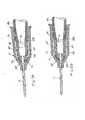
- FIG. 13is a cross-sectional side view of yet another alternative catheter assembly provided in accordance with aspects of the present invention, which is generally designated 200.
- the catheter assembly 200incorporates similar components as the assembly shown in FIGs. 8C and 9D , including a catheter tube 12 attached to a catheter hub 14, a needle 16 attached to a needle hub 18, a hemostatic valve 46, a valve opener 48 comprising a pair of legs 60 (only one shown) positioned in corresponding channels 28 in the catheter hub 14, a wiper (not shown) attached to either the catheter hub 14 or the valve opener 48, and a tip protector 202 for blocking the needle tip 72.
- a third housing 204is incorporated for accommodating the tip protector.
- the wiper(not shown) may be attached to the third housing 204, distal of the tip protector 202, for wiping the needle as the needle is retracted following catheterization.
- the third housing 204incorporates a rear plate or panel 206 attached to an enclosed housing section 208 for closing an opening 207 on the enclosed housing section 208.
- the opening 207 on the enclosed housing section 208allows the tip protector 202 to be placed therein during assembly.
- the rear plate 206may be attached to the housing section 208 using adhesive, welding, or detents.
- the enclosed housing section 208may incorporate an opening on a side, orthogonal to the rear plate 206.
- the third housing 204incorporates a pair of arms 210 each comprising a hook 212.
- the two hooks 212are configured to engage the two bumps 36 to retain the third housing 204 to the catheter hub 14 in a ready to use position.
- the two arms 210are preferably flexible to provide a gripping force against the two bumps 36, which is higher than the frictional force to withdraw the needle through the tip protector 202, hemostatic valve 46, and catheter 12.
- the two arms 210can be biased radially outward to increase the gripping force. Further, the two arms can be biased inwardly against the needle shaft to decrease the gripping force after the needle is withdrawn proximal of the arms 210.
- the needle 16is retracted proximally away from the catheter tube 12 in the same mariner as previously discussed (i.e., to the right of FIGs. 13 and 14 ).
- the tip protector 202engages the needle 16 and further proximal movement of the needle 16 causes the tip protector 202 to pull on the rear plate 206 of the third housing 204, which then disengages the two hooks 212 from the two bumps 36.
- the gripping force between the two hooks 212 and the two bumps 36should be less than the gripping force between the tip protector 202 and the needle 16.
- the tip protector 202comprises a proximal wall 216 comprising an opening 218, an arm 220 comprising an opening 222 ( FIG. 13 ), and a distal wall 214 at a distal end of the arm 220.
- the proximal wall 216 and the arm 220define an angle ⁇ therebetween.
- the end edge 224 of the tip protector 202is biased against the side of the needle 16 and the angle ⁇ has a ready angle value ⁇ ready .
- the activated positionFIGs.
- the angle ⁇increases to a protected angle value ⁇ protected , which is larger than the ready angle value ⁇ ready
- the armis further canted and the opening 222 on the arm grips the needle to engage the needle without a crimp.
- Fig. 15shows a longitudinal section of a further embodiment of a valve opener 193.
- the actuating end 194is connected with two legs 195, one of which is shown in Fig. 15 .
- a wiper in the form of a ring lip 197is provided wherein this ring lip 197 tapers in distal direction.
- This lip 197can be integrated with the actuating end 194 by injection molding.
- the passage 196has on the proximal side a portion with a larger taper of 60° followed by a portion with a taper of 4°.
- a tip protectorother than those specifically incorporated herein may be use, and rather than two equally long legs on a valve opener, a single leg or two legs with dissimilar lengths may be use.
- a third housingmay be incorporated to house the tip protector and the third housing positioned between the catheter hub and the needle hub as described in US application Ser. No.
Landscapes
- Health & Medical Sciences (AREA)
- Life Sciences & Earth Sciences (AREA)
- Heart & Thoracic Surgery (AREA)
- Engineering & Computer Science (AREA)
- Public Health (AREA)
- Veterinary Medicine (AREA)
- Biomedical Technology (AREA)
- Hematology (AREA)
- Animal Behavior & Ethology (AREA)
- General Health & Medical Sciences (AREA)
- Biophysics (AREA)
- Anesthesiology (AREA)
- Physics & Mathematics (AREA)
- Pathology (AREA)
- Medical Informatics (AREA)
- Molecular Biology (AREA)
- Surgery (AREA)
- Pulmonology (AREA)
- Manufacturing & Machinery (AREA)
- Vascular Medicine (AREA)
- Environmental & Geological Engineering (AREA)
- Infusion, Injection, And Reservoir Apparatuses (AREA)
- Media Introduction/Drainage Providing Device (AREA)
Abstract
Description
- Catheter assemblies are generally discussed herein with particular discussions extended to catheter assemblies having a tip protector, a valve, a valve opener, and optionally a needle wiper.
- Insertion procedure for an IV catheter assembly contains four basic steps: (1) the healthcare worker inserts the needle and catheter together into the patient's vein; (2) after insertion into the vein with the needle point, the catheter is forwarded into the vein of the patient by the healthcare worker pushing the catheter with his or her finger; (3) the healthcare worker withdraws the needle by grasping the hub end (opposite the point end) while at the same time applying pressure to the patient's skin at the insertion site with his or her free hand to stop the flow of blood through the catheter; and (4) the healthcare worker then tapes the exposed end of the catheter (the catheter hub) to the patient's skin and connects it to the source of the fluid to be administered into the patient's vein.
- The problem is that, immediately after the withdrawal of the needle from the patient's vein, the healthcare worker, who is at this time involved in at least two urgent procedures, must place the exposed needle tip at a nearby location and address the tasks required to accomplish the needle withdrawal. It is at this juncture that the exposed needle tip creates a danger of an accidental needle stick, which, under the circumstances, leaves the healthcare worker vulnerable to the transmission of various dangerous blood-borne pathogens, including AIDS and hepatitis.
- Other needle types similarly expose healthcare workers to risks of accidental needle sticks. For example, a doctor administering an injection, using a straight needle, a Huber needle, an epidural needle, etc., may place the used needle on a tray for subsequent disposal by a nurse. For the period between placing the used needle on a tray or a work station to the time it is discarded, the used needle is a potential source for disease transmissions for those that work near or around the needle.
- Accordingly, all needles should be covered immediately following use to ensure greater worker safety. Ideally, the procedure for covering the needle tip should be passive, self activating, or at least simple to perform. In addition, the device for covering the needle should be reliable and robust.
- More advantageously, a valve should be incorporated in the catheter assembly to minimize blood exposure following successful catherization. In addition, as blood comes in contact with the needle and is deposited on the needle, the needle assembly should further incorporate means for wiping the needle of the deposited blood upon retracting the needle.
US 2006/0155245 discloses a catheter insertion device having a needle protective element, a check valve, and a valve actuating element.- According to the present invention, there is provided a safety catheter assembly comprising:
- a catheter hub comprising a housing comprising an exterior surface and an interior surface defining an interior cavity; a catheter tube attached to the catheter hub and extending distally of the catheter hub; a needle hub comprising a housing comprising an exterior surface and an interior surface defining an interior cavity; a needle having a needle tip attached to the needle hub and projecting distally of the needle hub and into the catheter tube; a valve comprising a top surface, a skirt depending therefrom, and an opening on the top surface having the needle projecting therethrough; a valve opener for opening the valve and positioned in the interior cavity of the catheter hub proximal of the valve; a safety device for covering the needle comprising a tip protector housing for receiving the needle tip in a protected position and having a housing section positioned proximally of a proximal end of the catheter hub in a ready position; and wherein the valve opener comprises two proximally extending legs having a gap there between, the valve opener being sized and shaped to be pushed distally towards the valve to transfer a force imparted by an IV-set Luer connector to the valve.
- In accordance with aspects of the present invention, there is provided a catheter assembly comprising: a first hub comprising a housing comprising an exterior surface and an interior surface defining an interior cavity; a tube attached to the first hub and extending distally of the first hub; a second hub comprising a housing comprising an exterior surface and an interior surface defining an interior cavity; a needle having a needle tip attached to the second hub and projecting distally of the second hub and into the tube; a valve comprising a top surface, a skirt depending therefrom, and an opening on the top surface having the needle projecting therethrough; a valve opener comprising an actuating end, at least one leg extending proximally therefrom, and a wiper comprising a perimeter defining an opening and the needle in contact with the perimeter for wiping the needle as the needle is retracted away from the tube.
- Other aspects of the present invention include a catheter assembly comprising: a) a catheter hub comprising a housing comprising an exterior surface and an interior surface defining an interior cavity; b) a catheter tube attached to the catheter hub and extending distally of the catheter hub; c) a needle hub comprising a housing; d) a needle having a needle tip attached to the needle hub and projecting distally of the needle hub and into the catheter tube; e) a valve for limiting blood backflow positioned in the interior cavity of the catheter hub; f) a valve opener for opening the valve positioned proximally of the valve; and g) a tip protector positioned adjacent the valve opener for blocking the needle tip, wherein the tip protector comprises: (1) a tip protector housing having an interior surface; (2) a first arm extending from a distal wall of the tip protector housing biased towards the interior surface of the catheter hub; (3) a second arm extending from a proximal wall of the tip protector housing biased towards the interior surface of the catheter hub; and (4) a third arm extending from the proximal wall of the tip protector housing biased against a side of the needle.
- In accordance with other aspects of the present invention, there is provided a catheter assembly comprising: a catheter hub comprising a housing defining an interior cavity and having a catheter tube extending distally thereof; a needle hub comprising a housing defining an interior cavity and having a needle having a needle tip extending distally thereof; the needle projecting into the catheter tube; a hemostatic valve positioned within the interior cavity of the catheter hub having an opening; a valve opener positioned adjacent the hemostatic valve and comprising an actuating end comprising a cone section and a pair of legs defining a gap extending proximally thereof; a wiper having the needle passing therethrough for wiping the needle as the needle is retracted from the catheter tube; and wherein a tip protector comprising an arm and a wall comprising an opening and is positioned in the gap defined by the two legs.
- Still yet in accordance with other aspects of the present invention include provisions for registering a pair of legs on the valve opener to the catheter hub by forming two axially extending undercut within the interior wall surface of the catheter hub for cooperating with the two legs.
- In a preferred embodiment of the present invention, a raised bump or projection is formed within the interior cavity of the catheter hub for retaining a tip protector within the catheter hub during retraction of the needle hub away from the catheter hub.
- In yet other aspects of the present invention, a wiper in the form of an O-ring is used to wipe the needle from blood deposits.
- Other aspects and features of the catheter assemblies provided herein may be better appreciated as the same become better understood with reference to the specification, claims, and appended drawings.
- The appended drawings include:
FIG. 1 is a cross-sectional side view of a catheter assembly provided in accordance with aspects of the present invention;FIG. 2 is a cross-sectional side view of the catheter ofFIG. 1 with the needle and needle hub removed therefrom;FIG. 3 is a partial cross-sectional side view of a safety catheter assembly provided in accordance with aspects of the present invention, which includes a valve, a valve opener, and a tip protector;FIG. 4 is a partial cross-sectional side view of the safety catheter assembly ofFIG. 3 with the needle hub, needle, and tip protector removed therefrom;FIG. 5A is a cross-sectional side view of the catheter assembly ofFIG. 4 with an IV set luer connector coupled to the catheter hub and pushing a valve opener distally into the valve;FIG. 5B is a cross-sectional side view of an alternative catheter assembly, similar to the assembly ofFIGs. 3-5A , wherein the valve opener does not incorporate barbs to permit disengagement with the valve upon retraction of the IV-set luer connector;FIG. 6 is a cross-sectional side view of a needle hub and needle with a tip protector covering the needle tip;FIG. 7 is a perspective view of the tip protector ofFIG. 6 ;FIG. 8A is a plan view of a wiper provided in accordance with aspects of the present invention, which includes two cut-outs;FIG. 8B is a perspective view of a valve opener provided in accordance with aspects of the present invention having a wiper, according toFIG. 8A , attached to a proximally facing attachment surface;FIG. 8C is a cross-sectional side view of a catheter assembly provided in a accordance with aspects of the present invention having the valve opener ofFIG. 8B , including the wiper, positioned internally of the catheter hub;FIG. 9A is a plan view of a first alternative wiper provided in accordance with aspects of the present invention;FIG. 9B is a plan view of a second alternative wiper provided in accordance with aspects of the present invention;FIG. 9C is a plan view of a third alternative wiper provided in accordance with aspects of the present invention;FIG. 9D is a cross-sectional side view of a catheter assembly provided in a accordance with aspects of the present invention having a wiper positioned distally of a valve and valve opener;FIG. 10A is a perspective view of a needle projecting through a valve opener having a wiper attached thereto for wiping the needle;FIG. 10B is a partial perspective and cross-sectional view of the valve opener ofFIG. 10A ;FIG. 11 is a partial perspective and cross-sectional view of an alternative valve opener having a needle passing therethrough and a wiper that resembles an O-ring;FIG. 12 is a partial perspective and cross-sectional view of an alternative valve opener having a needle passing therethrough and a wiper that is registered to an annular groove;FIG. 13 is a cross-sectional side view of yet another alternative catheter assembly provided in accordance with aspects of the present invention, which includes a third housing positioned between a catheter and a needle hub; andFIG. 14 is a cross-sectional side view of the catheter assembly ofFIG. 13 taken along an orthogonal plane.- The detailed description set forth below in connection with the appended drawings is intended as a description of the presently preferred embodiments of a catheter assembly for use with valves and needle tip protectors provided in accordance with aspects of the present invention and is not intended to represent the only forms in which the present invention may be constructed or utilized. The description sets forth the features and the steps for constructing and using the catheter assembly of the present invention in connection with the illustrated embodiments. It is to be understood, however, that the same or equivalent functions and structures may be accomplished by different embodiments are also intended to be encompassed within the spirit and scope of the invention, especially those incorporating a combination of features shown in the different embodiments included herein. As denoted elsewhere herein, like element numbers are intended to indicate like or similar elements or features.
- Referring now to
FIG. 1 , a partial cross-sectional side view of a catheter assembly provided in accordance with aspects of the present invention is shown, which is generally designated 10. Thecatheter assembly 10 comprises acatheter tube 12 attached to acatheter hub 14 having aneedle 16, which is attached to aneedle hub 18, projecting through thecatheter tube 12 in a ready to use position. Theneedle 16 has a sharpenedneedle tip 72 and a crimp, bump, orclip engagement section 73. Thecatheter hub 14 comprises an exterior surface 20 and an interior surface defining aninterior cavity 24. A needlehub nose section 26 preferably projects into theinterior cavity 24 of thecatheter hub 14 and a combination groove and projection (not shown) incorporated between thecatheter hub 14 andneedle hub 18 to fix relative angular rotation between the two. - In one exemplary embodiment, a pair of diametrically
opposed channels 28 are formed in theinterior wall surface 22 of thecatheter hub 14. Thechannels 28 are formed as indentations in theinterior wall surface 22 of the catheter hub and each has a length measured about 20 % to about 85 % of the length of the catheter hub, measured from theproximal threads 30 to thedistal shoulder 32 adjacent a frusto-conical nose section 34. Thechannels 28 may be formed by known injection molding techniques. - In one exemplary embodiment, a pair of
projections 36 are incorporated in theinterior cavity 24 of thecatheter hub 14. The twoprojections 36 are preferably symmetrical about the twochannels 28 and each comprises two ends 38 that contact the twochannels 28. In an alternative embodiment, the two ends 38 can be spaced apart from the twochannels 28 and eachprojection 36 may be an indentation rather than a raised bump. Thus, in a preferred embodiment, theinterior cavity 24 of the catheter hub, at the two projections or bumps 36, have a diameter measured from one bump to another bump, called a bump diameter, that is smaller than the diameter of the interior cavity of thecatheter hub 14 measured from apoint 40 adjacent the two bumps, called a bore diameter. Also at the two projection or bumps 36, theinterior cavity 24 of thecatheter hub 14 has a diameter measured from onechannel 28 to anotherchannel 28, called a mean channel diameter, that is larger than the bump diameter and thebore diameter 40. FIG. 2 is a cross-section side view of thecatheter hub 14 ofFIG. 1 taken along a transverse plane and with theneedle 16 andneedle hub 18 removed therefrom. Although relative positions of thechannel 28 to thehub 14 and of thebump 36 to thechannel 28 are shown, they can each vary proximally towards theproximal opening 42 or distally towards thenose section 34 and relative to one another or in a rotation relative to theneedle bevel 72 without deviating from the spirit and scope of the present invention.- Referring now to
FIG. 3 , a partial cross-sectional side-view of a safety IV catheter assembly provided in accordance with aspects of the present invention is shown, which is generally designated 44. In one exemplary embodiment, thecatheter assembly 44 comprises ahemostatic valve 46, avalve opener 48, and atip protector 50 positioned inside theinterior cavity 24 of thecatheter hub 14 ofFIG. 1 . Thetip protector 50 may be the same as one of the many tip protectors shown and described inUS Pat. No. 6,616,630 to Woehr et al. , the contents of which are expressly incorporated herein by reference as if set forth in full. Thetip protector 50 is seated within theinterior cavity 24 by moving the tip protector distally in the direction of theneedle tip 72 until the two elbow sections 74 (only one shown) located between the twoarms 76 and the two fingers or distal walls 78 (only one shown) move distally of theprojection 36 inside the catheter hub. Alternatively, two recesses may be incorporated instead of the two bumps for interacting with the twoelbow sections 74. - The
hemostatic valve 46 may be made from a thermoplastic elastomer (TPE), such as polyisoprene or silicone rubber, and generally speaking comprises askirt section 52 and a top 54 having a cut-out 56 comprising a plurality of slits, such as three slits resembling a three-sided star or a single slit, for expanding the cut-out when deflected. Thehemostatic valve 46 is widely commercially available and is a well known component in the relevant art. In accordance with aspects of the present invention, a plurality of bumps, stretched ridges, or protuberances may be incorporated around the external circumference of theskirt section 52 for ensuring sufficient air flow between thevalve skirt 52 and theinside surface 22 of the catheter hub for purposes of blood flashback. In yet other aspects of the present invention, the cut-out 56 is provided with a sufficient gap to permit air movement for purposes of blood flashback. In the latter alternative embodiment, an air tight seal is preferred between the exterior skirt section and theinterior surface 22 of the catheter hub. - The
valve opener 48 comprises an actuatingend 58 and a pair oflegs 60. In one exemplary embodiment, the actuatingend 58 comprises a frusto-conical shape distal end configured to project against the top 54 of thevalve 46, as further discussed below with reference toFIG. 5 . In accordance with aspects of the present invention, the actuatingend 58 comprises one or more undulating surfaces orbarbs 62 for mating engagement with the cut-out 56 and plurality of slits on the hemostatic valve. - In one exemplary embodiment, the
valve opener 48 is formed from a hard plastic material, which may be a polycarbonate material, a polyoximethylene material or the like. The twolegs 60 are formed such that they spread radially outwardly relative to theneedle shaft 16. In a specific aspect of the present invention, the twolegs 60 are aligned with the twochannels 28 and are registered to the two channels. The length and geometry of thevalve opener 48 are such that thenose section 58 abuts theskirt section 52 of thevalve 46 and the valve exerts a counter force pushing the two proximal ends 64 of the twolegs 60 against theproximal ledge 66 of each respective channel 28 (See, e.g.,FIG. 9D ). Theskirt section 52 is therefore under a slight compression caused by thenose section 58 of thevalve opener 48 pushing against the skirt section. Alternatively, thenose section 58 may be spaced apart from and not contact thevalve 46 in the ready to use position (FIG. 3 ). - The two
legs 60 are preferably registered to the twochannels 28 without a radial compression. In other words, the radial most tip 68 of eachleg 60 is not biased against the wall surface 70 of therespective channel 28. However, a slight radial compression may be practiced without deviating from the spirit and scope of the present invention. - Referring now to
FIG. 4 , the safety IV catheter assembly ofFIG. 3 is shown with theneedle 16,tip protector 50, andneedle hub 18 removed. In practice, this represents the position of the catheter following successful catheterization. As disclosed in the '630 Woehr et al. patent, when theneedle 16 is withdrawn following catheterization, thetip protector 50 is withdrawn with the needle and remains with the needle to block theneedle tip 72. In certain aspects of the present invention, a crimp, bump, orclip engagement section 73 is used to engage the opening on thetip protector 50 to secure the tip protector to the needle.US patent application Ser. No. 11/496,769 to Kevin Woehr , entitled Needle Assembly and Components Thereof discloses a tip protector comprising side walls for surrounding the needle tip, which may be useable with the catheter assemblies provided in accordance with aspects of the present invention. The contents of the '769 application are expressly incorporated herein by reference. In yet other aspects of the present invention, thetip protector 50 incorporates an opening that cants over to grip the needle. Exemplary tip protectors that cant over to grip the needle are disclosed inU.S. Pat. No. 6,709,419 to Kevin Woehr , patent application Ser. No.10/677,810 to Pat Latona 10/954,041 to Matthew Kohler - As shown in
FIG. 4 , thetop section 54 of thevalve 46 recoils when no longer deflected by the needle and the cut-out 56 closes to form a seal. Thus, blood flow from the direction of thecatheter tube 12 is stopped. Although not depicted, the exterior circumference of thevalve 46 is wedged into the interior cavity and the valve is under compression by the interference fit. As the blood flow has been stopped, a health care worker can take his or her time in connecting an IV set luer connector to thecatheter hub 14, fix the catheter hub with tape to the patient, and dispose of the used needle without excessive blood leakage through the catheter hub. Alternatively, the valve can provide a semi-permeable seal, which gives the health care worker ample time to make the required connections, fixations, and disposal of used needles before blood would exit thecatheter hub 14 at theproximal end 42. - Assuming the
opening 42 of thehub 14 defines aplanar surface 83, in one exemplary embodiment, theend surface 80 of the twolegs 60 at the two proximal ends 64 are positioned at an angle to theplanar surface 83. The twolegs 60 should also project radially inwardly of the nominal internal diameter of thecatheter hub 14 at a position just proximal to the two proximal ends 64, i.e., thebore diameter 40. As further discussed below with reference toFIG. 5 , the projection provides a contact surface on eachproximal end 64 of thevalve opener 48 for urging by a IV-set Luer connector. In an alternative embodiment, the end surfaces are generally parallel to theplanar surface 83 defined by theopening 42. FIG. 5A depicts an IV-setLuer connector 86 pushed into theopening 42 of thecatheter hub 14. As theconnector 86 is pushed distally forward, itsdistal end 88 abuts the twoend surfaces 80 of theseal opener 48 and advances theopener 48 distally forward. Theopener 48 in turn moves into thetop area 54 of the seal and forces the cut-out 56 to deflect. The combination friction andbarbs 62 on the actuatingend 58 of thevalve opener 48 allow the two to remain engaged. Thevalve 46 remains opened and fluid communication is provided between thecatheter tube 12 and theinterior cavity 24 of thecatheter hub 14. Medicaments, IV solutions, or other fluids may now be introduced through theconnector 86 andcatheter 12. If the IV setluer connector 86 is subsequently withdrawn from thecatheter hub 14, then thevalve 46 would remain open and consequently there could be blood leakage. Alternatively, the actuatingend 58 does not incorporatebarbs 62 as shown inFIG. 5B thus allowing thetop section 54 of the valve to separate from the actuatingend 58. This allows thevalve opener 48 to be moved proximally by action of the resilient top section while at the same time allows the cut-out to reseal itself.FIG. 6 is a cross-sectional side view of aneedle hub 90 having aneedle 92 attached at end thereof and atip protector 94 covering theneedle tip 96. As known in the art, a flashback plug (not shown) is normally placed in the proximal end of theneedle hub 90. Thetip protector 94 is the same as that shown and described in application Ser. No.11/496,769 tip protector 94 comprises afirst protector body 98 surrounded by asecond protector body 100. The- first protector body comprises ashort arm 102 and along arm 104, which both have portions that, at least in part, extend to one side of the centerline of theneedle 92. The second protector body 100 (FIG. 7 ) partially surrounds the-first protector body and comprises adeflector plate 106, afront wall 108 having anopening 110 and two side walls 112 (only one shown). When thetip protector 94 is in the protective position over the needle tip (FIG. 6 ), the needle tip is surrounded by the plurality of walls.- In one exemplary embodiment, the
combination needle hub 90,needle 92, andtip protector 94 ofFIG. 6 may be used with the catheter shown in FTG. 4. Theprojection 36 on thehub 14 would be positioned proximally relative to the apex 115 of thelong arm 104 of thetip protector 94 to retain thetip protector 94 in thecatheter hub 14. Alternatively, theprojections 36 may be omitted and thearm 102 anddeflector plate 106 resiliently engage theinterior wall surface 22 to retain thetip protector 94 to the catheter hub. - Generally speaking, when a needle is withdrawn from a catheter tube following successful catheterization, residue blood may deposit on the needle shaft. The sight and presence of blood on a retracted needle are undesirable and potentially contagious. Thus; in accordance with aspects of the present invention, wipers are provided for wiping the needle upon retracting the same from a catheter.
FIGs. 8A ,9A, 9B, and 9C are plan views of fourdifferent wipers FIGs. 8B and9D , the wipers are configured to be attached to a valve opener or a catheter hub for scraping or wiping fluid from the surface of a needle as the needle is withdrawn from a catheter tube. FIG. 8A shows awiper 176 made from a liquid impermeable film, such as blown PE film, comprising a generally circular configuration with two cut-outs 178. The cut-outs 178 are sized and shaped to permit assembly to a valve opener and are incorporated along a perimeter of the wiper. Thus, the cut-out shape and the wiper's overall configuration may vary depending on the mounting surface of the valve opener. In one exemplary embodiment, thewiper 176 has a solid center section (i.e., no center opening) configured for puncturing by a needle during assembly, as further discussed below.FIG. 8B is a perspective view of avalve opener 180 provided in accordance with aspects of the present invention. In one exemplary embodiment, the valve opener comprises anactuating end 182 and twolegs 184 connected to and extend proximally of the actuating end. Like thevalve opener 48 shown inFIG. 3 , the actuatingend 182 comprises a frusto-conical configuration and incorporates barbs (not shown inFIG. 8B ) and a passage for accommodating a needle. In one specific aspect of the present invention, the passage is funnel-like in shape. The twolegs 184, while shown extended parallel and offset to an axis defined by the center of the passage, may be angled radially outwardly as they extend proximally. The two legs may also incorporate a slight arc or bend, such as that shown inFIG. 3 .- In one exemplary embodiment, a proximally facing
wall surface 186 on the actuating end is provided and serves as a mounting surface for a wiper. Thewiper 176 ofFIG. 8A may be attached to the mountingsurface 186 with the cut-outs 178 aligned to the twolegs 184. The wiper can be welded to the mounting surface or glued thereto with an appropriate adhesive, such cyanoacrylate or UV cure adhesive. In practice, thevalve opener 180 andwiper 176 may be installed as shown inFIG. 8C and when aneedle 16 is inserted, theneedle tip 72 penetrates the wiper and the wiper subsequently provides a wiping function for the needle. When thewiper 176 is penetrated by theneedle tip 72, theneedle 16 will open and dilate the wiper putting the needle in a close contact relationship with thewiper 176. Thus, when anupstream section 146 of the needle 16 (i.e., upstream of the wiper) is exposed to blood from blood flashback and is subsequently withdrawn proximally (i.e., to the right ofFIG. 8C ) to remove theneedle 16, the close contact relationship between thewiper 176 and theneedle 16 allows the wiper to wipe blood deposits from the needle as the needle is being withdrawn. Consequently, when theneedle 16 is fully retracted from thevalve opener 180, the needle will appear clean, or at least for the most part visually blood-free, and the tip protector that surrounds the needle tip will likely remain visually blood-free. FIG. 9A shows awiper 116 having a generally circular configuration of afirst wiper material 122, which may be a microporous plastic film membrane filter, surrounding a plasticinner layer 124, such as a polyethylene (PE) blown film layer. Theouter wiper material 122 is preferably air permeable to permit blood flashback. The membrane may be made from PP (polypropylene) or PA (polyamide or Nylon®) spun bound fibers, such as those known in the art from flashback plugs. In a preferred embodiment, theinner layer 124 is plastic film configured for puncturing by a needle when assembling the combination needle hub and needle to a catheter hub, such as the one shown inFIG. 3 having a wiper attached to the valve opener. The wiper should be sufficiently thin so as to not damage the needle tip when the same is passed therethrough. The inner and outer layers can be welded to another.- In one exemplary embodiment, the
wiper 118 shown inFIG. 9B is identical to thewiper 116 shown inFIG. 9A with the exception of apre-formed opening 126. Theopening 126 is preferably sized the same as a needle diameter. In other words, the opening is sized with a zero clearance around the outside diameter of the needle. More preferably, theopening 126 is sized the same as the inside diameter of a catheter tip, which is slightly smaller than the outside diameter of the needle. FIG. 9C shows yet another wiper embodiment 120 provided in accordance with aspects of the present invention. In one exemplary embodiment, the wiper comprises asingle membrane layer 128 having anopening 126, which has a same diameter size as the inside diameter of a catheter tip. A plurality of micro-holes are formed in themembrane layer 128 for venting air. The holes are each sized about 3 µm (micro-meter) to about 8 µm. The membrane may be made from PE, or spun bound PA or PP.FIG. 9D is a cross-sectional side view of an alternative safety IV catheter assembly provided in accordance with aspects of the present invention, which is generally designated 188. Thecatheter assembly 188 is similar to thecatheter assembly 44 ofFIG. 3 and includes acatheter tube 12 andhub 14, aneedle 16 andneedle hub 18, atip protector 50, avalve opener 48, and avalve 46. However, in the alternative safetyIV catheter assembly 188, an air permeable fluidimpermeable wiper 190 is incorporated distal of thevalve 46. In one exemplary embodiment, thewiper 190 may be one of thewipers FIGs. 9A, 9B, or 9C and may be attached to a tube bushing 192 for retaining thecatheter tube 12 to thecatheter hub 14. The tube bushing 192 is preferably made from a thermoplastic material to facilitate attaching thewiper 90 thereon, such as by adhesive or welding. In an alternative embodiment (not shown), a shoulder or seat may be provided within the interior cavity of thecatheter hub 14 for accommodating thewiper 190.FIG. 10A is a partial perspective view of aneedle 130 projecting through avalve opener 132 having awiper 134 attached thereto. Thevalve opener 132 is similar to the valve opener shown and described with reference toFIGs. 3-5 .FIG. 10A , as well asFIGs. 10B-12 discussed further below, may be viewed as a safety catheter assembly, such as the assembly ofFIG. 3 , shown without a catheter hub, a needle hub, or a tip protector for clarity and for purposes of discussing only the functions of the wiper. Accordingly, it should be understood that the components shown inFIG. 10A , as well as those inFIGs. 10B-12 , are adapted for use with a catheter hub, needle hub, and tip protector in the same manner as those described with reference toFIGs. 1-5 . Furthermore, the tip protector is not limited to those shown but also includes those expressly incorporated herein by reference.- In one exemplary embodiment, the
valve opener 132 comprises twolegs 136 extending proximally of a frusto-conicalshape actuating end 138. Although not shown, the actuatingend 138 may comprise an undulating surface or barbs for gripping engagement with a hemostatic valve. Theactuating end 138 comprises a generally planarproximally facing surface 140 and a passage orlumen 142 for receiving theneedle 130. The two legs are radially spaced apart from theneedle 130 and has a gap 143 therebetween for accommodating a tip protector. FIG. 10B is a partial perspective partial cross-sectional rotated and magnified view of thevalve opener 132 ofFIG. 10A . Thevalve opener 132 is shown with thewiper 134 having a ring or cylinder seated within a recessed section of theactuating end 138. Thewiper 134 maybe insert molded into theopener 132. Thetab 144 is the material left between the wiping ring and the cavity gate. Alternatively the wiper can be integral with the actuating end 13 8. Thewiper 134 comprises apassage 152 having a first diameter that is slightly larger than the outside diameter of theneedle 130 and alip 154 having a second diameter, which is preferably the size of the inside diameter of a catheter tip of a catheter tube, that theneedle 130 is configured to position in. As discussed above with reference toFIGs. 8C and 9D , when theneedle 130 is withdrawn proximally, blood deposits along the upstream end (distal) 146 of the needle is wiped off by thewiper 150.FIG. 10B shows thevalve opener 132 having asingle leg 136. However, a valve opener with two legs having a gap therebetween is more preferred. The gap between the twolegs 136 is configured to accommodate atip protector 50, such as that shown inFIGs. 3 and9D .FIG. 11 is a partial perspective partial cross-sectional side view of analternative valve opener 156 provided in accordance with aspects of the present invention. Thevalve opener 156 is shown with aneedle 130 projecting through theactuating end 138. In the' embodiment shown, a well or recessedarea 158 is incorporated for accommodating a wiper in a form of an O-ring 160, which may be made from an elastomeric or TPE material. TheOaring 160 can be slid into the well 158 and a retainingring 162 pushed against the O-ring 160 to retain the O-ring therein. The retainingring 162 is secured to the well 158 using simple interference fit. In an alternative embodiment, the retainingring 162 is welded to the valve opener.- As before, the O-
ring 160 is preferably in a contact relationship with theneedle 130 so that it may wipe the needle as the needle is withdrawn proximally (to the right inFIG. 11 ) away from theopener 156. Theopener 156 is shown having a gap between the twolegs 136 for accommodating a tip protector (not shown). Theopener 156 and theneedle 130 are configured to be used with a catheter hub in the same manner as the opener and needle shown inFIG. 3 . FIG. 12 is a partial cross-sectional perspective view of yet anotheralternative valve opener 166 provided in accordance with aspects of the present invention. In the embodiment shown, anannular groove 168 is incorporated in a well 158 for accommodating an elastomeric orTPE wiper 170. Thewiper 170 resembles a flattened O-ring, like a doughnut, but may in fact also be an O-ring. This configuration enables a common valve opener to be used with various needle outside and O-ring inside diameters. Thewiper 170 is retained within the well 158 without a separate retaining ring, such as thering 162 inFIG. 11 . Thewiper 170 may be snapped-fit into thegroove 168 during assembling.FIG. 13 is a cross-sectional side view of yet another alternative catheter assembly provided in accordance with aspects of the present invention, which is generally designated 200. Thecatheter assembly 200 incorporates similar components as the assembly shown inFIGs. 8C and 9D , including acatheter tube 12 attached to acatheter hub 14, aneedle 16 attached to aneedle hub 18, ahemostatic valve 46, avalve opener 48 comprising a pair of legs 60 (only one shown) positioned in correspondingchannels 28 in thecatheter hub 14, a wiper (not shown) attached to either thecatheter hub 14 or thevalve opener 48, and atip protector 202 for blocking theneedle tip 72. However, rather than placing thetip protector 202 in a gap defined by-the twolegs 60 in thevalve opener 48, athird housing 204 is incorporated for accommodating the tip protector. Additionally, the wiper (not shown) may be attached to thethird housing 204, distal of thetip protector 202, for wiping the needle as the needle is retracted following catheterization.- In one exemplary embodiment, the
third housing 204 incorporates a rear plate orpanel 206 attached to anenclosed housing section 208 for closing anopening 207 on theenclosed housing section 208. Theopening 207 on theenclosed housing section 208 allows thetip protector 202 to be placed therein during assembly. Therear plate 206 may be attached to thehousing section 208 using adhesive, welding, or detents. Alternatively, theenclosed housing section 208 may incorporate an opening on a side, orthogonal to therear plate 206. - The
third housing 204 incorporates a pair ofarms 210 each comprising ahook 212. The twohooks 212 are configured to engage the twobumps 36 to retain thethird housing 204 to thecatheter hub 14 in a ready to use position. The twoarms 210 are preferably flexible to provide a gripping force against the twobumps 36, which is higher than the frictional force to withdraw the needle through thetip protector 202,hemostatic valve 46, andcatheter 12. Alternatively the twoarms 210 can be biased radially outward to increase the gripping force. Further, the two arms can be biased inwardly against the needle shaft to decrease the gripping force after the needle is withdrawn proximal of thearms 210. - Following successful catheterization, the
needle 16 is retracted proximally away from thecatheter tube 12 in the same mariner as previously discussed (i.e., to the right ofFIGs. 13 and 14 ). As theneedle tip 72 moves proximally of thedistal wall 214 of thetip protector 202, thetip protector 202 engages theneedle 16 and further proximal movement of theneedle 16 causes thetip protector 202 to pull on therear plate 206 of thethird housing 204, which then disengages the twohooks 212 from the twobumps 36. Thus, the gripping force between the twohooks 212 and the twobumps 36 should be less than the gripping force between thetip protector 202 and theneedle 16. - Referring now to
FIG. 14 , thetip protector 202 comprises aproximal wall 216 comprising anopening 218, anarm 220 comprising an opening 222 (FIG. 13 ), and adistal wall 214 at a distal end of thearm 220. Theproximal wall 216 and thearm 220 define an angle □ therebetween. In a ready to use position (not shown), theend edge 224 of thetip protector 202 is biased against the side of theneedle 16 and the angle □ has a ready angle value □ready. When in the activated position (FIGs. 13 and 14 ), the angle □ increases to a protected angle value □protected, which is larger than the ready angle value □ready When this occurs, the arm is further canted and theopening 222 on the arm grips the needle to engage the needle without a crimp. Fig. 15 shows a longitudinal section of a further embodiment of avalve opener 193. The actuating end 194 is connected with twolegs 195, one of which is shown inFig. 15 . In thepassage 196 for accommodating a needle a wiper in the form of aring lip 197 is provided wherein thisring lip 197 tapers in distal direction. Thislip 197 can be integrated with the actuating end 194 by injection molding. It is also possible to provide thering lip 197 of a suitable other material than the actuating end 194 wherein thering lip 197 can be connected with the actuating end by a two-component injection molding: Thepassage 196 has on the proximal side a portion with a larger taper of 60° followed by a portion with a taper of 4°.- Although limited catheter assembly embodiments and their components have been specifically described and illustrated, many modifications, combinations, and variations will be apparent to those skilled in the art. For example, the length, size, colors, and appearance of the needle hub and catheter hub may be modified, a tip protector other than those specifically incorporated herein may be use, and rather than two equally long legs on a valve opener, a single leg or two legs with dissimilar lengths may be use. Additionally, rather than placing a tip protector in the catheter hub for blocking the needle tip, a third housing may be incorporated to house the tip protector and the third housing positioned between the catheter hub and the needle hub as described in
US application Ser. No. 10/109,797 US application Ser. No. 10/468,923 entitled "NEEDLE ASSEMBLY WITH PROTECTIVE ELEMENT", and inUS Patent No. 7,125,397 , the contents of which are expressly incorporated herein by reference. Furthermore, it is understood and contemplated that features specifically discussed for one valve embodiment, wiper, valve opener, or tip protector may be adopted for inclusion with another valve embodiment provided the functions are compatible. For example, the needle and tip protector ofFIG. 6 , the valve opener and wiper ofFIG. 10A , and the hemostatic valve ofFIG. 8C may be use with the catheter hub ofFIG. 2 , even though the overall combination was not expressly discussed. Accordingly, it is to be understood that the catheter assemblies and their components constructed according to principles of this invention may be embodied other than as specifically described herein. The invention is also defined in the following claims.
Claims (9)
- A safety catheter assembly comprising:a catheter hub comprising a housing comprising an exterior surface and an interior surface defining an interior cavity;a catheter tube attached to the catheter hub and extending distally of the catheter hub;a needle hub comprising a housing comprising an exterior surface and an interior surface defining an interior cavity;a needle having a needle tip attached to the needle hub and projecting distally of the needle hub and into the catheter tube;a valve comprising a top surface, a skirt depending therefrom, and an opening on the top surface having the needle projecting therethrough;a valve opener for opening the valve and positioned in the interior cavity of the catheter hub proximal of the valve;a safety device for covering the needle comprising a tip protector housing for receiving the needle tip in a protected position and having a housing section positioned proximally of a proximal end of the catheter hub in a ready position; andwherein the valve opener comprises two proximally extending legs having a gap there between, the valve opener being sized and shaped to be pushed distally towards the valve to transfer a force imparted by an IV-set Luer connector to the valve.
- The safety catheter assembly according to claim 1, wherein the skirt comprises one or more ridges along an outer surface thereof to permit venting around the skirt section.
- The safety catheter assembly according to either of claims 1 or 2, wherein the valve comprises one or more slits that are deflectable by a distal end of the valve opener.
- The safety catheter assembly according to claim 3, wherein the distal end of the valve opener comprises a nose section having a frusto-conical shape for projecting through the slits.
- The safety catheter assembly according to any preceding claim, wherein the safety device comprises a movable resilient member.
- The safety catheter assembly of claim 5, wherein the safety device for covering the needle tip comprises an arm extending into an open proximal end of the catheter hub.
- The safety catheter assembly according to any preceding claim, wherein the valve opener comprises an actuating end for opening the valve, the legs extending proximally of the actuating end.
- The safety catheter assembly according to claim 7, wherein the actuating end comprises an undulating surface or barbs for gripping engagement with the valve.
- The safety catheter assembly according to any preceding claim, wherein the safety device comprises a proximal wall having an opening and two arms each having a distal wall for blocking the needle tip.
Applications Claiming Priority (4)
| Application Number | Priority Date | Filing Date | Title |
|---|---|---|---|
| US11/592,595US8308691B2 (en) | 2006-11-03 | 2006-11-03 | Catheter assembly and components thereof |
| EP11007265.9AEP2420283B1 (en) | 2006-11-03 | 2007-11-02 | Catheter assembly and components thereof |
| PCT/EP2007/009520WO2008052790A2 (en) | 2006-11-03 | 2007-11-02 | Catheter assembly and components thereof |
| EP07819546.8AEP2083898B1 (en) | 2006-11-03 | 2007-11-02 | Catheter assembly and components thereof |
Related Parent Applications (3)
| Application Number | Title | Priority Date | Filing Date |
|---|---|---|---|
| EP07819546.8ADivisionEP2083898B1 (en) | 2006-11-03 | 2007-11-02 | Catheter assembly and components thereof |
| EP11007265.9ADivisionEP2420283B1 (en) | 2006-11-03 | 2007-11-02 | Catheter assembly and components thereof |
| EP11007265.9ADivision-IntoEP2420283B1 (en) | 2006-11-03 | 2007-11-02 | Catheter assembly and components thereof |
Publications (2)
| Publication Number | Publication Date |
|---|---|
| EP3097939A1true EP3097939A1 (en) | 2016-11-30 |
| EP3097939B1 EP3097939B1 (en) | 2025-01-01 |
Family
ID=37887513
Family Applications (6)
| Application Number | Title | Priority Date | Filing Date |
|---|---|---|---|
| EP07846527.5ANot-in-forceEP2094342B1 (en) | 2006-11-03 | 2007-11-02 | Catheter apparatus with infusion port and valves |
| EP11007265.9AActiveEP2420283B1 (en) | 2006-11-03 | 2007-11-02 | Catheter assembly and components thereof |
| EP13162599.8AActiveEP2638926B1 (en) | 2006-11-03 | 2007-11-02 | Catheter assembly and components thereof |
| EP07819546.8AActiveEP2083898B1 (en) | 2006-11-03 | 2007-11-02 | Catheter assembly and components thereof |
| EP12198721.8ANot-in-forceEP2572750B1 (en) | 2006-11-03 | 2007-11-02 | Catheter device with infusion port and valves |
| EP16161892.1AActiveEP3097939B1 (en) | 2006-11-03 | 2007-11-02 | Catheter assembly and components thereof |
Family Applications Before (5)
| Application Number | Title | Priority Date | Filing Date |
|---|---|---|---|
| EP07846527.5ANot-in-forceEP2094342B1 (en) | 2006-11-03 | 2007-11-02 | Catheter apparatus with infusion port and valves |
| EP11007265.9AActiveEP2420283B1 (en) | 2006-11-03 | 2007-11-02 | Catheter assembly and components thereof |
| EP13162599.8AActiveEP2638926B1 (en) | 2006-11-03 | 2007-11-02 | Catheter assembly and components thereof |
| EP07819546.8AActiveEP2083898B1 (en) | 2006-11-03 | 2007-11-02 | Catheter assembly and components thereof |
| EP12198721.8ANot-in-forceEP2572750B1 (en) | 2006-11-03 | 2007-11-02 | Catheter device with infusion port and valves |
Country Status (14)
| Country | Link |
|---|---|
| US (7) | US8308691B2 (en) |
| EP (6) | EP2094342B1 (en) |
| KR (3) | KR101497246B1 (en) |
| CN (4) | CN103007384B (en) |
| AU (1) | AU2007315205B2 (en) |
| BR (2) | BRPI0718313A2 (en) |
| DE (1) | DE202006017732U1 (en) |
| DK (1) | DK2094342T3 (en) |
| ES (3) | ES2782118T3 (en) |
| MY (6) | MY161722A (en) |
| PL (1) | PL2094342T3 (en) |
| RU (2) | RU2477639C2 (en) |
| WO (1) | WO2008052790A2 (en) |
| ZA (1) | ZA200903403B (en) |
Cited By (2)
| Publication number | Priority date | Publication date | Assignee | Title |
|---|---|---|---|---|
| WO2017029361A1 (en)* | 2015-08-18 | 2017-02-23 | B. Braun Melsungen Ag | Catheter devices with valves and related methods |
| US11850377B2 (en) | 2018-12-17 | 2023-12-26 | B. Braun Melsungen Ag | Catheter assemblies and related methods |
Families Citing this family (177)
| Publication number | Priority date | Publication date | Assignee | Title |
|---|---|---|---|---|
| JPH0673429B2 (en)* | 1991-05-11 | 1994-09-21 | 有限会社光陽機械製作所 | Pon rice cracker manufacturing method and apparatus |
| DE20210394U1 (en) | 2002-07-04 | 2002-09-12 | B. Braun Melsungen Ag, 34212 Melsungen | catheter introducer |
| EP1907042B1 (en) | 2005-07-06 | 2009-03-11 | Vascular Pathways Inc. | Intravenous catheter insertion device and method of use |
| US8162894B2 (en)* | 2005-09-09 | 2012-04-24 | Cook Medical Technologies Llc | Valve opener |
| US8308691B2 (en) | 2006-11-03 | 2012-11-13 | B. Braun Melsungen Ag | Catheter assembly and components thereof |
| WO2008066991A2 (en)* | 2006-08-30 | 2008-06-05 | Arthur Harris | Continuous feed hypodermic syringe with self contained cartridge dispenser |
| JP4994775B2 (en) | 2006-10-12 | 2012-08-08 | 日本コヴィディエン株式会社 | Needle point protector |
| EP2150304B1 (en) | 2007-05-07 | 2010-12-01 | Vascular Pathways Inc. | Intravenous catheter insertion and blood sample devices and method of use |
| US9101748B2 (en)* | 2008-05-08 | 2015-08-11 | Becton, Dickinson And Company | Push-button blood control |
| US8366684B2 (en)* | 2008-05-12 | 2013-02-05 | Becton, Dickinson And Company | Intravenous catheter blood control device |
| US7938805B2 (en)* | 2008-05-19 | 2011-05-10 | Becton, Dickinson And Company | Radially compressible blood control valve |
| WO2009148969A1 (en) | 2008-06-02 | 2009-12-10 | Sta-Med, Llc | Needle cover assembly for a syringe |
| US10089443B2 (en) | 2012-05-15 | 2018-10-02 | Baxter International Inc. | Home medical device systems and methods for therapy prescription and tracking, servicing and inventory |
| US8388583B2 (en)* | 2009-08-20 | 2013-03-05 | Becton, Dickinson And Company | Systems and methods for providing a flushable catheter assembly |
| US8361038B2 (en) | 2009-02-11 | 2013-01-29 | Becton, Dickinson And Company | Systems and methods for providing a flow control valve for a medical device |
| US8574203B2 (en)* | 2009-02-11 | 2013-11-05 | Becton, Dickinson And Company | Systems and methods for providing a flushable catheter assembly |
| US8679063B2 (en)* | 2009-02-11 | 2014-03-25 | Becton, Dickinson And Company | Systems and methods for providing a catheter assembly |
| US8469928B2 (en)* | 2009-02-11 | 2013-06-25 | Becton, Dickinson And Company | Systems and methods for providing a flushable catheter assembly |
| USRE45896E1 (en)* | 2009-02-11 | 2016-02-23 | Becton, Dickinson And Company | Systems and methods for providing a catheter assembly |
| US9399120B2 (en)* | 2009-03-02 | 2016-07-26 | Becton, Dickinson And Company | Bi-directional cannula feature capture mechanism |
| DE202009009602U1 (en) | 2009-07-15 | 2009-12-10 | B. Braun Melsungen Ag | Catheter device with needle guard |
| US8323249B2 (en) | 2009-08-14 | 2012-12-04 | The Regents Of The University Of Michigan | Integrated vascular delivery system |
| DE102009052962A1 (en) | 2009-11-12 | 2011-06-01 | B. Braun Melsungen Ag | catheter introducer |
| US8911405B2 (en)* | 2009-12-14 | 2014-12-16 | Jms Co., Ltd. | Needle device |
| US11925779B2 (en) | 2010-05-14 | 2024-03-12 | C. R. Bard, Inc. | Catheter insertion device including top-mounted advancement components |
| US10384039B2 (en) | 2010-05-14 | 2019-08-20 | C. R. Bard, Inc. | Catheter insertion device including top-mounted advancement components |
| US9872971B2 (en) | 2010-05-14 | 2018-01-23 | C. R. Bard, Inc. | Guidewire extension system for a catheter placement device |
| US8932258B2 (en) | 2010-05-14 | 2015-01-13 | C. R. Bard, Inc. | Catheter placement device and method |
| US9950139B2 (en) | 2010-05-14 | 2018-04-24 | C. R. Bard, Inc. | Catheter placement device including guidewire and catheter control elements |
| US8814833B2 (en) | 2010-05-19 | 2014-08-26 | Tangent Medical Technologies Llc | Safety needle system operable with a medical device |
| WO2011146769A2 (en) | 2010-05-19 | 2011-11-24 | Tangent Medical Technologies Llc | Integrated vascular delivery system |
| US8162882B2 (en) | 2010-06-23 | 2012-04-24 | Sta-Med, Llc | Automatic-locking safety needle covers and methods of use and manufacture |
| US8652104B2 (en) | 2010-06-25 | 2014-02-18 | Smiths Medical Asd, Inc. | Catheter assembly with seal member |
| US9545495B2 (en) | 2010-06-25 | 2017-01-17 | Smiths Medical Asd, Inc. | Catheter assembly with seal member |
| US9028425B2 (en)* | 2010-07-15 | 2015-05-12 | Becton, Dickinson And Company | Vented blood sampling device |
| US8361020B2 (en) | 2010-07-15 | 2013-01-29 | Becton, Dickinson And Company | Catheter assembly and pierced septum valve |
| US8357119B2 (en) | 2010-07-15 | 2013-01-22 | Becton, Dickinson And Company | Catheter assembly and pierced septum valve |
| US8864715B2 (en) | 2010-09-08 | 2014-10-21 | Becton, Dickinson And Company | Assembly method for catheter with blood control |
| US8932259B2 (en) | 2010-09-13 | 2015-01-13 | Becton, Dickinson And Company | Catheter assembly |
| US8690833B2 (en) | 2011-01-31 | 2014-04-08 | Vascular Pathways, Inc. | Intravenous catheter and insertion device with reduced blood spatter |
| ES2835652T3 (en) | 2011-02-25 | 2021-06-22 | Bard Inc C R | Medical component insertion device including a retractable needle |
| US8641675B2 (en) | 2011-03-07 | 2014-02-04 | Becton, Dickinson And Company | Systems and methods for preventing septum damage in an intravascular device |
| USD655406S1 (en) | 2011-03-07 | 2012-03-06 | Becton, Dickinson And Company | Vented flushable catheter assembly |
| US9259554B2 (en) | 2011-03-07 | 2016-02-16 | Becton, Dickinson And Company | Systems and methods to compensate for compression forces in an intravascular device |
| ES2662356T3 (en) | 2011-04-27 | 2018-04-06 | Kpr U.S., Llc | Safety IV catheter assemblies |
| USD903101S1 (en) | 2011-05-13 | 2020-11-24 | C. R. Bard, Inc. | Catheter |
| WO2012166746A1 (en) | 2011-05-31 | 2012-12-06 | Sta-Med, Llc | Blood collection safety devices and methods of use and manufacture |
| EP2760521B1 (en) | 2011-09-26 | 2016-01-06 | Covidien LP | Safety iv catheter and needle assembly |
| WO2013048975A1 (en) | 2011-09-26 | 2013-04-04 | Covidien Lp | Safety catheter |
| US9155864B2 (en) | 2011-10-06 | 2015-10-13 | Becton, Dickinson And Company | Multiple use blood control valve with center and circumferential slits |
| US9155876B2 (en)* | 2011-10-06 | 2015-10-13 | Becton, Dickinson And Company | Port valve of a blood control catheter |
| US9089671B2 (en)* | 2011-10-06 | 2015-07-28 | Becton, Dickinson And Company | Systems and methods for sealing a septum within a catheter device |
| US9358364B2 (en) | 2011-10-06 | 2016-06-07 | Becton, Dickinson And Company | Activator attachment for blood control catheters |
| US9126012B2 (en) | 2011-10-06 | 2015-09-08 | Becton, Dickinson And Company | Intravenous catheter with duckbill valve |
| US9155863B2 (en) | 2011-10-06 | 2015-10-13 | Becton, Dickinson And Company | Multiple use stretching and non-penetrating blood control valves |
| US8834422B2 (en) | 2011-10-14 | 2014-09-16 | Covidien Lp | Vascular access assembly and safety device |
| US9155866B2 (en) | 2012-09-13 | 2015-10-13 | Becton, Dickinson And Company | Luer securement device |
| SE537334C2 (en)* | 2012-04-27 | 2015-04-07 | Vigmed Ab | Protective device for needle point and mounting device |
| US8622967B2 (en)* | 2012-05-15 | 2014-01-07 | Becton, Dickinson And Company | Over-the-needle intravenous catheter assembly with integrated intravenous tubing |
| US9579486B2 (en) | 2012-08-22 | 2017-02-28 | Becton, Dickinson And Company | Blood control IV catheter with antimicrobial properties |
| US9272088B2 (en)* | 2012-09-13 | 2016-03-01 | Becton, Dickinson And Company | Intravenous catheter inserter |
| EP2916905A4 (en) | 2012-11-12 | 2016-11-09 | Icu Medical Inc | MEDICAL CONNECTION |
| WO2014120741A1 (en) | 2013-01-30 | 2014-08-07 | Vascular Pathways, Inc. | Systems and methods for venipuncture and catheter placement |
| US9695323B2 (en) | 2013-02-13 | 2017-07-04 | Becton, Dickinson And Company | UV curable solventless antimicrobial compositions |
| US9750928B2 (en) | 2013-02-13 | 2017-09-05 | Becton, Dickinson And Company | Blood control IV catheter with stationary septum activator |
| US9320881B2 (en)* | 2013-02-13 | 2016-04-26 | Becton, Dickinson And Company | Septum actuator with insertion depth limiter and compression compensator |
| US9717886B2 (en) | 2013-03-12 | 2017-08-01 | Teleflex Medical Incorporated | Safety clip for a needle |
| US11224724B2 (en) | 2013-03-12 | 2022-01-18 | Teleflex Medical Incorporated | Catheter insertion device |
| US10357635B2 (en) | 2013-03-12 | 2019-07-23 | Teleflex Medical Incorporated | Catheter insertion device |
| US9623210B2 (en)* | 2013-03-15 | 2017-04-18 | B. Braun Melsungen Ag | Catheter assemblies with wipeable bloodstop and related methods |
| CN104043180B (en)* | 2013-03-15 | 2019-07-16 | B.布劳恩梅尔松根股份公司 | Valve Regulated Catheter Assembly and Related Methods |
| US9114231B2 (en)* | 2013-03-15 | 2015-08-25 | B. Braun Melsungen Ag | Valved catheter assemblies and related methods |
| CN203694357U (en)* | 2013-03-15 | 2014-07-09 | B.布劳恩梅尔松根股份公司 | safety IV catheter |
| US8979802B2 (en)* | 2013-03-15 | 2015-03-17 | B. Braun Melsungen Ag | Safety IV catheter assembly with seal |
| US9381320B2 (en) | 2013-03-18 | 2016-07-05 | Becton, Dickinson And Company | Multiple-use intravenous catheter assembly septum and septum actuator |
| US10500376B2 (en) | 2013-06-07 | 2019-12-10 | Becton, Dickinson And Company | IV catheter having external needle shield and internal blood control septum |
| GB2508570C2 (en) | 2013-08-21 | 2025-07-30 | Braun Melsungen Ag | Catheter assembly |
| US10918837B2 (en)* | 2013-12-04 | 2021-02-16 | B. Braun Melsungen Ag | Safety needle assemblies and related methods |
| US9919136B2 (en)* | 2013-12-04 | 2018-03-20 | B. Braun Melsungen Ag | Catheter assembly with reusable valve |
| WO2015082566A1 (en)* | 2013-12-04 | 2015-06-11 | B. Braun Melsungen Ag | Needle assembly with sealed notch and related methods |
| US9795766B2 (en)* | 2013-12-04 | 2017-10-24 | B. Braun Melsungen Ag | Catheter assembly blood control device and related methods |
| AR098613A1 (en) | 2013-12-06 | 2016-06-01 | Genentech Inc | APPLIANCES AND METHODS FOR THE ADMINISTRATION OF MEDICINES IN LOW VOLUMES |
| MY180155A (en) | 2013-12-20 | 2020-11-23 | Braun Melsungen Ag | Safety needle assemblies and related methods |
| CN104922748A (en)* | 2014-01-08 | 2015-09-23 | B.布劳恩梅尔松根股份公司 | Catheter Assemblies With Valves And Related Methods |
| US9750925B2 (en) | 2014-01-21 | 2017-09-05 | Becton, Dickinson And Company | Ported catheter adapter having combined port and blood control valve with venting |
| CA2937744C (en) | 2014-02-04 | 2022-08-09 | Icu Medical, Inc. | Self-priming systems and methods |
| DE202015100585U1 (en) | 2014-02-07 | 2015-02-26 | B. Braun Melsungen Ag | Catheter devices with safety mechanisms |
| SG11201608547XA (en) | 2014-04-18 | 2016-11-29 | Becton Dickinson Co | Needle capture safety interlock for catheter |
| US10376686B2 (en) | 2014-04-23 | 2019-08-13 | Becton, Dickinson And Company | Antimicrobial caps for medical connectors |
| US9675793B2 (en) | 2014-04-23 | 2017-06-13 | Becton, Dickinson And Company | Catheter tubing with extraluminal antimicrobial coating |
| US9789279B2 (en) | 2014-04-23 | 2017-10-17 | Becton, Dickinson And Company | Antimicrobial obturator for use with vascular access devices |
| US10154904B2 (en)* | 2014-04-28 | 2018-12-18 | Edwards Lifesciences Corporation | Intravascular introducer devices |
| US10232088B2 (en) | 2014-07-08 | 2019-03-19 | Becton, Dickinson And Company | Antimicrobial coating forming kink resistant feature on a vascular access device |
| US10112033B2 (en) | 2014-07-08 | 2018-10-30 | Becton, Dickinson And Company | Intravenous needle assembly having blood dispensing capabilities |
| WO2016007650A1 (en)* | 2014-07-08 | 2016-01-14 | Applied Medical Resources Corporation | Highly responsive instrument seal |
| CN110974255B (en)* | 2014-08-26 | 2022-10-11 | 威蓝诺血管股份有限公司 | System and method for drawing blood through a peripheral IV catheter |
| WO2016037127A1 (en) | 2014-09-05 | 2016-03-10 | C.R. Bard, Inc. | Catheter insertion device including retractable needle |
| US11511052B2 (en) | 2014-11-10 | 2022-11-29 | Becton, Dickinson And Company | Safety IV catheter with V-clip interlock and needle tip capture |
| US10543343B2 (en) | 2014-12-23 | 2020-01-28 | B. Braun Melsungen Ag | Needle assemblies with flashback indicator and related methods |
| US20160220805A1 (en) | 2015-01-30 | 2016-08-04 | Smiths Medical Asd, Inc. | Intravenous catheter assembly design |
| JP6640861B2 (en)* | 2015-01-30 | 2020-02-05 | スミスズ メディカル エーエスディー,インコーポレイティド | Releasable catheter hub retainer |
| CA2976805C (en)* | 2015-02-23 | 2020-04-07 | C.R. Bard, Inc. | Access system |
| EP3261705B1 (en)* | 2015-02-26 | 2019-08-14 | B. Braun Melsungen AG | Iv catheter assemblies with injection ports |
| USD903100S1 (en) | 2015-05-01 | 2020-11-24 | C. R. Bard, Inc. | Catheter placement device |
| US10449331B2 (en)* | 2015-05-13 | 2019-10-22 | B. Braun Melsungen Ag | Catheter devices with seals and related methods |
| CN113350614A (en) | 2015-05-15 | 2021-09-07 | C·R·巴德股份有限公司 | Catheter placement device including extendable needle safety feature |
| US10173002B2 (en)* | 2015-06-08 | 2019-01-08 | B. Braun Melsungen Ag | Catheter devices with needle guards and related methods |
| US10744305B2 (en) | 2015-10-28 | 2020-08-18 | Becton, Dickinson And Company | Ergonomic IV systems and methods |
| US10245416B2 (en) | 2015-10-28 | 2019-04-02 | Becton, Dickinson And Company | Intravenous catheter device with integrated extension tube |
| US10639455B2 (en) | 2015-10-28 | 2020-05-05 | Becton, Dickinson And Company | Closed IV access device with paddle grip needle hub and flash chamber |
| US10814106B2 (en) | 2015-10-28 | 2020-10-27 | Becton, Dickinson And Company | Soft push tabs for catheter adapter |
| US10493244B2 (en) | 2015-10-28 | 2019-12-03 | Becton, Dickinson And Company | Extension tubing strain relief |
| US10357636B2 (en) | 2015-10-28 | 2019-07-23 | Becton, Dickinson And Company | IV access device having an angled paddle grip |
| US10549072B2 (en) | 2015-10-28 | 2020-02-04 | Becton, Dickinson And Company | Integrated catheter with independent fluid paths |
| US10525237B2 (en) | 2015-10-28 | 2020-01-07 | Becton, Dickinson And Company | Ergonomic IV systems and methods |
| US10729889B2 (en) | 2015-11-13 | 2020-08-04 | B. Braun Melsungen Ag | Needle devices with dual diameter cannula and related methods |
| WO2017103103A1 (en) | 2015-12-18 | 2017-06-22 | B. Braun Melsungen Ag | Needle devices with adjustable grips and related methods |
| US10682495B2 (en)* | 2015-12-18 | 2020-06-16 | B. Braun Melsungen Ag | Needle devices with adjustable grips and related methods |
| EP4309725A3 (en) | 2016-02-18 | 2024-04-17 | Smiths Medical ASD, Inc. | Closed system catheter |
| US10894149B2 (en)* | 2016-03-08 | 2021-01-19 | Acclarent, Inc. | Dilation catheter assembly with adjustment features |
| JP7134410B2 (en)* | 2016-04-19 | 2022-09-12 | ニプロ株式会社 | Indwelling needle and indwelling needle assembly |
| CN107335114B (en)* | 2016-04-29 | 2020-06-05 | 黄翔 | Needle head structure |
| WO2018025094A1 (en)* | 2016-08-01 | 2018-02-08 | Poly Medicure Limited | Intravenous catheter apparatus with safety function and pressure controlled valve element |
| TWI576132B (en)* | 2016-08-08 | 2017-04-01 | Safe infusion connection | |
| AU2017312325B2 (en) | 2016-08-19 | 2022-11-17 | B. Braun Melsungen Ag | Needle assemblies and related methods |
| CN106362263A (en)* | 2016-08-30 | 2017-02-01 | 苏州鱼跃医疗科技有限公司 | Introducing needle protective device used for catheter assembly, catheter assembly and indwelling needle |
| US10493262B2 (en)* | 2016-09-12 | 2019-12-03 | C. R. Bard, Inc. | Blood control for a catheter insertion device |
| USD819802S1 (en) | 2016-10-05 | 2018-06-05 | Becton, Dickinson And Company | Catheter adapter |
| USD835262S1 (en) | 2016-10-05 | 2018-12-04 | Becton, Dickinson And Company | Intravenous catheter assembly |
| US10238852B2 (en) | 2016-10-05 | 2019-03-26 | Becton, Dickinson And Company | Septum housing |
| USD844781S1 (en) | 2016-10-05 | 2019-04-02 | Becton, Dickinson And Company | Needle hub |
| USD837368S1 (en) | 2016-10-05 | 2019-01-01 | Becton, Dickinson And Company | Catheter adapter grip |
| EP3532143B1 (en) | 2016-10-27 | 2020-08-19 | B. Braun Melsungen AG | Catheter devices with valves and related methods |
| USD808013S1 (en) | 2016-10-27 | 2018-01-16 | Smiths Medical Asd, Inc. | Catheter |
| EP3568192A4 (en) | 2017-01-12 | 2021-01-20 | I-V Access Technology, Inc. | Catheter valves |
| EP3585471B1 (en) | 2017-03-01 | 2025-01-01 | C. R. Bard, Inc. | Catheter insertion device |
| EP4480525A3 (en) | 2017-04-13 | 2025-04-09 | Teleflex Medical Incorporated | Catheter insertion device |
| EP3630257A4 (en) | 2017-05-26 | 2021-03-17 | Piper Access, LLC | Catheter delivery devices, systems, and methods |
| EP3634562A1 (en) | 2017-06-09 | 2020-04-15 | B. Braun Melsungen AG | Adhesive encased protective caps for needle devices and related methods |
| JP7264819B2 (en)* | 2017-09-29 | 2023-04-25 | テルモ株式会社 | catheter assembly |
| US11813426B2 (en) | 2017-10-06 | 2023-11-14 | Amgen Inc. | Drug delivery device including seal member for needle of syringe |
| CN110152182A (en)* | 2018-02-13 | 2019-08-23 | 白玉 | Medical tubing opener |
| ES2980192T3 (en) | 2018-03-07 | 2024-09-30 | Bard Access Systems Inc | Guidewire advancement and blood reflux systems for a medical device insertion system |
| DE202018101646U1 (en)* | 2018-03-23 | 2019-06-27 | Jens Ebnet | IV catheter |
| JP2021521921A (en) | 2018-04-18 | 2021-08-30 | ベー・ブラウン・メルズンゲン・アクチエンゲゼルシャフトB.Braun Melsungen Aktiengesellschaft | Catheter assembly and related methods |
| WO2019228991A1 (en) | 2018-05-29 | 2019-12-05 | B. Braun Melsungen Ag | Peripheral venous catheter assemblies with sensors and related methods |
| US11857320B2 (en) | 2018-06-08 | 2024-01-02 | Smiths Medical Asd, Inc. | Blood sequestration device and method |
| US11291755B2 (en) | 2018-06-19 | 2022-04-05 | Aadi Innovations LLC | Arteriovenous access catheter with protectable inline needle |
| KR102076414B1 (en)* | 2018-07-25 | 2020-03-02 | 정준영 | Medical needle |
| USD921884S1 (en) | 2018-07-27 | 2021-06-08 | Bard Access Systems, Inc. | Catheter insertion device |
| WO2020120404A1 (en)* | 2018-12-10 | 2020-06-18 | B. Braun Melsungen Ag | Catheter devices with blood control systems and related methods |
| USD884160S1 (en) | 2019-02-25 | 2020-05-12 | iMed Technology, Inc. | Huber safety needle |
| US10413712B1 (en)* | 2019-02-28 | 2019-09-17 | Injectimed, Inc. | Luer-activated valves |
| CN113365688B (en)* | 2019-03-28 | 2024-10-01 | 泰尔茂株式会社 | Catheter assembly |
| US11529080B2 (en)* | 2019-04-22 | 2022-12-20 | The Monarch Company Llc | Blood collection assembly |
| WO2021001450A1 (en)* | 2019-07-02 | 2021-01-07 | B. Braun Melsungen Ag | Blood collectable peripheral intravenous catheter assemblies and related methods |
| BR112022000189A2 (en) | 2019-07-08 | 2022-02-22 | Braun Melsungen Ag | Hybrid safety spring clip for sharp medical devices and related methods |
| CA3151126A1 (en) | 2019-08-19 | 2021-02-25 | Becton, Dickinson And Company | Midline catheter placement device |
| AU2020338266A1 (en) | 2019-08-29 | 2022-02-24 | B. Braun Melsungen Ag | Extended dwell and midline catheters and related methods |
| CA3169051A1 (en) | 2019-09-10 | 2021-03-18 | Medsource International Llc | An intravenous catheter device |
| CN115052650A (en)* | 2019-12-20 | 2022-09-13 | 埃布内特医疗有限责任公司 | Vein indwelling cannula |
| US12042611B2 (en)* | 2020-03-23 | 2024-07-23 | Becton, Dickinson And Company | Needle shield |
| US12144938B2 (en) | 2020-04-27 | 2024-11-19 | Bard Access Systems, Inc. | Preloaded stylet valve compatibility |
| AT523531B1 (en)* | 2020-05-05 | 2021-09-15 | Univ Wien Med | Device for connecting a cannula to a container |
| AU2021358382A1 (en) | 2020-10-06 | 2023-05-18 | B. Braun Melsungen Ag | Needle assemblies and related methods |
| CN113080956B (en)* | 2021-04-09 | 2023-05-02 | 自贡市第一人民医院 | Blood sampling indwelling needle |
| KR102257215B1 (en)* | 2021-04-12 | 2021-05-27 | 주재욱 | Intravenous tube catheter equipped with a blood reflux preventing |
| KR102257208B1 (en)* | 2021-04-12 | 2021-05-27 | 주재욱 | Intravenous tube catheter to prevent clot formation and leackage in a catheter |
| CN113069114B (en)* | 2021-04-27 | 2025-07-11 | 中国人民解放军陆军军医大学第一附属医院 | A rat femoral artery blood sampling device |
| US12337123B2 (en) | 2021-05-06 | 2025-06-24 | Medsource Labs, Llc | Safety intravenous cannula |
| US20220355093A1 (en)* | 2021-05-10 | 2022-11-10 | Becton, Dickinson And Company | Annular valve securement within a catheter assembly |
| BR112023002666A2 (en) | 2021-06-14 | 2023-12-19 | Braun Melsungen Ag | CATHETER SET AND METHOD OF MANUFACTURING A CATHETER SET |
| JP2024535161A (en) | 2021-09-29 | 2024-09-30 | ベー・ブラウン・メルズンゲン・アクチエンゲゼルシャフト | CATHETER WITH GUIDEWIRE ADAPTER AND ASSOCIATED METHODS - Patent application |
| US12186497B2 (en) | 2022-01-14 | 2025-01-07 | Medsource International Llc | Intravenous cannula |
| US20250195844A1 (en)* | 2022-01-31 | 2025-06-19 | Nipro Corporation | Needle assembly |
| US11607525B1 (en) | 2022-06-30 | 2023-03-21 | I-V Access Technology, Inc. | Methods and devices for vascular access |
| WO2025087904A1 (en) | 2023-10-23 | 2025-05-01 | B. Braun Melsungen Ag | Peripheral safety catheters and related methods |
Citations (4)
| Publication number | Priority date | Publication date | Assignee | Title |
|---|---|---|---|---|
| US5156596A (en)* | 1991-02-04 | 1992-10-20 | Menlo Care, Inc. | Catheter with changeable number of lumens |
| US5405323A (en)* | 1994-02-22 | 1995-04-11 | Aeroquip Corporation | Catheter check valve assembly |
| WO2003011381A1 (en)* | 2001-07-31 | 2003-02-13 | Delta Med S.R.L. | Protective device for a needle |
| US20060155245A1 (en) | 2002-07-04 | 2006-07-13 | Kevin Woehr | Catheter insertion device |
Family Cites Families (216)
| Publication number | Priority date | Publication date | Assignee | Title |
|---|---|---|---|---|
| US3416567A (en) | 1964-02-20 | 1968-12-17 | Viggo Ab | Syringe valve |
| GB1199498A (en)* | 1967-03-29 | 1970-07-22 | Latex Products Proprietary Ltd | Non-Return Valve for Medical Uses. |
| US3585996A (en)* | 1968-07-11 | 1971-06-22 | Levoy S Corp | Arterial catheter placement unit and method of use |
| US3662754A (en) | 1970-05-04 | 1972-05-16 | William X Halloran | Injection apparatus |
| US3727613A (en) | 1970-10-09 | 1973-04-17 | Voys Inc Le | Safety catheter placement assembly |
| US4143853A (en)* | 1977-07-14 | 1979-03-13 | Metatech Corporation | Valve for use with a catheter or the like |
| DE2817102C2 (en)* | 1978-04-19 | 1985-01-24 | Dr. Eduard Fresenius, Chemisch-pharmazeutische Industrie KG, 6380 Bad Homburg | Connector for plastic cannulas or venous catheters |
| DE3000903C1 (en) | 1980-01-11 | 1989-09-21 | Fresenius Chem Pharm Ind | Connection device for connecting cannulas, catheters or tubing |
| DE3100622A1 (en) | 1980-04-18 | 1982-02-25 | Dr. Eduard Fresenius, Chemisch-pharmazeutische Industrie KG, 6380 Bad Homburg | Connection device for the connection of cannulas, catheters, flexible tubes or the like |
| DE3210148C2 (en) | 1982-03-19 | 1985-11-21 | Fresenius AG, 6380 Bad Homburg | Connector |
| US4511359A (en)* | 1982-09-29 | 1985-04-16 | Manresa, Inc. | Sterile connection device |
| US4449693A (en)* | 1982-09-30 | 1984-05-22 | Gereg Gordon A | Catheter check valve |
| US4512766A (en)* | 1982-12-08 | 1985-04-23 | Whitman Medical Corporation | Catheter valve |
| DE3303073C1 (en) | 1983-01-29 | 1984-09-06 | B. Braun Melsungen Ag, 3508 Melsungen | Injection valve for infusion devices |
| US4578063A (en)* | 1984-09-14 | 1986-03-25 | W. L. Gore & Assoc., Inc. | Central venous catheter |
| US4673399A (en)* | 1985-06-06 | 1987-06-16 | Enrico Bertucci | Disposable injection transmitter |
| US4929235A (en)* | 1985-07-31 | 1990-05-29 | Universal Medical Instrument Corp. | Self-sealing percutaneous tube introducer |
| DE8528780U1 (en) | 1985-10-09 | 1985-11-14 | B. Braun Melsungen Ag, 3508 Melsungen | Injection valve |
| US5116021A (en) | 1986-03-04 | 1992-05-26 | Deka Products Limited Partnership | Quick-disconnect valve |
| US4765588A (en)* | 1986-08-18 | 1988-08-23 | Vernay Laboratories, Inc. | Check valve for use with a syringe |
| GB8627808D0 (en)* | 1986-11-20 | 1986-12-17 | Cox J A | Sampling liquids from human/animal body |
| US4846811A (en) | 1987-01-29 | 1989-07-11 | International Medical Innovators, Inc. | Sliding sheath for medical needles |
| US4795432A (en)* | 1987-02-19 | 1989-01-03 | Karczmer Claude M | Shield assembly for hypodermic injection devices |
| US4762516A (en) | 1987-03-05 | 1988-08-09 | Luther Medical Products, Inc. | Assembly of needle catheter protector |
| US4927414A (en)* | 1987-04-29 | 1990-05-22 | Kulli John C | Syringe with safety retracting needle |
| US4772266A (en)* | 1987-05-04 | 1988-09-20 | Catheter Technology Corp. | Catheter dilator/sheath assembly and method |
| US4883461A (en) | 1987-05-15 | 1989-11-28 | Interface Biomedical Laboratories Corp. | Safety needle sheath in anti-reflux catheter having novel valve means |
| US4944725A (en)* | 1987-06-01 | 1990-07-31 | Mcdonald Michael | Safety needle apparatus |
| US4850961A (en) | 1987-07-30 | 1989-07-25 | Wanderer Alan A | Indwelling placement device with guard |
| US4790828A (en) | 1987-08-07 | 1988-12-13 | Dombrowski Mitchell P | Self-capping needle assembly |
| US4966586A (en) | 1987-09-04 | 1990-10-30 | Vaillancourt Vincent L | Closed system over-the-needle I.V. catheter |
| US4813938A (en)* | 1987-09-17 | 1989-03-21 | Raulerson J Daniel | Catheter introduction syringe |
| US4842591A (en)* | 1988-01-21 | 1989-06-27 | Luther Ronald B | Connector with one-way septum valve, and assembly |
| CA1335167C (en) | 1988-01-25 | 1995-04-11 | Steven C. Jepson | Pre-slit injection site and associated cannula |
| US5135489A (en) | 1988-01-25 | 1992-08-04 | Baxter International Inc. | Pre-slit injection site and tapered cannula |
| US4846809A (en)* | 1988-02-29 | 1989-07-11 | Winifred Sims | Needle tip protective device |
| DE3809127C1 (en)* | 1988-03-18 | 1989-04-13 | B. Braun Melsungen Ag, 3508 Melsungen, De | |
| US4874377A (en) | 1988-05-26 | 1989-10-17 | Davis Newgard Revocable Family Living Trust | Self-occluding intravascular cannula assembly |
| USRE34416E (en) | 1988-07-11 | 1993-10-19 | Critikon, Inc. | I.V. catheter with self-locating needle guard |
| US4952207A (en)* | 1988-07-11 | 1990-08-28 | Critikon, Inc. | I.V. catheter with self-locating needle guard |
| US4929241A (en)* | 1988-08-05 | 1990-05-29 | Kulli John C | Medical needle puncture guard |
| US4978344A (en) | 1988-08-11 | 1990-12-18 | Dombrowski Mitchell P | Needle and catheter assembly |
| AT391814B (en) | 1988-11-22 | 1990-12-10 | Hirnich Paul | CONNECTING PIECE FOR AN INFUSION DEVICE OD. DGL. |
| GB8829182D0 (en) | 1988-12-14 | 1989-01-25 | Univ Birmingham | Surgical instrument |
| US4964854A (en) | 1989-01-23 | 1990-10-23 | Luther Medical Products, Inc. | Intravascular catheter assembly incorporating needle tip shielding cap |
| US5458658A (en) | 1989-02-01 | 1995-10-17 | Sero-Guard Corporation | Positive locking needle-mounted needle guard for needle supported catheters |
| US5662610A (en)* | 1989-02-01 | 1997-09-02 | Sircom; Richard C. | Automatic needle guard tip protection |
| ES2081973T3 (en)* | 1989-02-01 | 1996-03-16 | Sero Guard Corp | AUTOMATIC DISPOSABLE HYPODERMIC NEEDLE PROTECTOR. |
| CA2044818C (en) | 1991-06-17 | 2004-01-27 | Richard Sircom | Needle-mounted needle guard for intravenous catheters |
| DE3913392A1 (en) | 1989-04-24 | 1990-10-25 | Sterimed Gmbh | CONNECTOR FOR CATHETER |
| US5092845A (en) | 1989-07-10 | 1992-03-03 | Critikon, Inc. | Catheter with needle gasket |
| US5135504A (en)* | 1989-07-17 | 1992-08-04 | Mclees Donald J | Needle tip guard |
| US5007901A (en) | 1989-11-24 | 1991-04-16 | Shields Jack W | Intravenous catheter insertion device |
| US5030205A (en) | 1989-12-18 | 1991-07-09 | Critikon, Inc. | Catheter assemblies for prevention of blood leakage |
| US5147327A (en)* | 1990-01-10 | 1992-09-15 | Johnson Gerald W | Hypodermic needle with protective sheath |
| US5053014A (en)* | 1990-02-01 | 1991-10-01 | Critikon, Inc. | Catheter with controlled valve |
| US5053017A (en) | 1990-02-28 | 1991-10-01 | Chamuel Steven R | Hypodermic needle safety clip |
| US5062836A (en) | 1990-03-14 | 1991-11-05 | The Kendall Company | Placement device for a catheter and guide wire |
| US5084023A (en)* | 1990-03-22 | 1992-01-28 | Critikon, Inc. | Bloodless catheter with self-shielding needle |
| US5010925A (en) | 1990-04-09 | 1991-04-30 | Vernay Laboratories, Inc. | Normally closed duckbill valve assembly |
| US5558651A (en)* | 1990-04-20 | 1996-09-24 | Becton Dickinson And Company | Apparatus and method for a needle tip cover |
| USRE38996E1 (en) | 1990-04-20 | 2006-02-28 | Becton, Dickinson And Company | Needle tip cover |
| US5108374A (en)* | 1990-05-02 | 1992-04-28 | Critikon, Inc. | Stickless catheter with manual shut-off valve |
| US5127905A (en)* | 1990-05-02 | 1992-07-07 | Critikon, Inc. | Stickless catheter with manual shut-off valve |
| US5051109A (en)* | 1990-07-16 | 1991-09-24 | Simon Alexander Z | Protector for catheter needle |
| US5077790A (en)* | 1990-08-03 | 1991-12-31 | Motorola, Inc. | Secure over-the-air registration of cordless telephones |
| US5085645A (en) | 1990-08-15 | 1992-02-04 | Becton, Dickinson And Company | Apparatus and method for a catheter adapter with valve |
| US5085648A (en) | 1990-09-13 | 1992-02-04 | Becton Dickinson And Company | Dual diameter needle with a smooth transition |
| US5154703A (en) | 1990-10-30 | 1992-10-13 | Care Medical Devices, Inc. | Bloodless catheter |
| US5152751A (en) | 1990-12-04 | 1992-10-06 | Kozlowski David J | Hypodermic needle safety shield |
| US5098405A (en) | 1991-01-31 | 1992-03-24 | Becton, Dickinson And Company | Apparatus and method for a side port cathether adapter with a one piece integral combination valve |
| US5312355A (en)* | 1991-07-09 | 1994-05-17 | H L Medical Inventions, Inc. | Splittable hemostatic valve and sheath and the method for using the same |
| GB9120416D0 (en) | 1991-09-25 | 1991-11-06 | Sterimatic Holdings Ltd | Catheter placement units |
| US5188607A (en)* | 1991-11-12 | 1993-02-23 | Thomas Wu | Valve catheter connector assembly |
| US5382230A (en)* | 1991-12-16 | 1995-01-17 | Thomas Jefferson University | Vascular access sheath for interventional devices |
| US5195980A (en)* | 1992-01-03 | 1993-03-23 | Thomas Medical Products, Inc. | Hemostatic valve |
| US5215528C1 (en) | 1992-02-07 | 2001-09-11 | Becton Dickinson Co | Catheter introducer assembly including needle tip shield |
| US5334159A (en)* | 1992-03-30 | 1994-08-02 | Symbiosis Corporation | Thoracentesis needle assembly utilizing check valve |
| US5180370A (en)* | 1992-05-18 | 1993-01-19 | Gillespie Elgene R | Safety hypodermic syringe with retractable needle |
| US5242393A (en)* | 1992-06-18 | 1993-09-07 | Becton, Dickinson And Company | Valved blunt cannula injection site |
| US5300033A (en)* | 1992-07-09 | 1994-04-05 | Unisurge, Inc. | Introducer assembly and valve construction for use therein |
| DK0606459T3 (en) | 1992-07-31 | 2001-08-13 | Luckhurst Anthony Henry Willia | Needle Protection Device |
| WO1994003232A1 (en)* | 1992-08-07 | 1994-02-17 | C.R. Bard, Inc. | Proximal cardiovascular catheter fitting with wide range passive seal |
| US5215525A (en) | 1992-09-29 | 1993-06-01 | Sturman Warren M | Safety casing for intravenous catheter needle |
| US5234410A (en)* | 1992-10-23 | 1993-08-10 | Vlv Associates | Catheter assembly |
| ES2105330T3 (en) | 1992-11-24 | 1997-10-16 | Braun Melsungen Ag | CATHETERIZATION INSTRUMENTAL. |
| US5458640A (en) | 1993-01-29 | 1995-10-17 | Gerrone; Carmen J. | Cannula valve and seal system |
| US5269771A (en) | 1993-02-24 | 1993-12-14 | Thomas Medical Products, Inc. | Needleless introducer with hemostatic valve |
| US5330435A (en) | 1993-04-08 | 1994-07-19 | Vaillancourt Vincent L | Valve for a catheter assembly |
| DE4311715C2 (en) | 1993-04-08 | 1996-02-01 | Fresenius Ag | Port cannula |
| US5300045A (en) | 1993-04-14 | 1994-04-05 | Plassche Jr Walter M | Interventional needle having an automatically capping stylet |
| US5380305A (en)* | 1993-04-20 | 1995-01-10 | Jerry D. Rockhold, Jr. | Hemostatic safety catheter-cannula assembly |
| US5334161A (en) | 1993-05-21 | 1994-08-02 | Simon Gurmarnik | Catheter with needle trap |
| US5584809A (en) | 1993-07-20 | 1996-12-17 | Graphic Controls Corporation | Safety catheter |
| US5697907A (en) | 1993-07-20 | 1997-12-16 | Graphic Controls Corporation | Safety catheter |
| US5344408A (en)* | 1993-08-06 | 1994-09-06 | Becton, Dickinson And Company | Break-away safety shield for needle cannula |
| US5352205A (en) | 1993-09-16 | 1994-10-04 | Lawrence Dales | Bloodless insertion catheter assembly |
| US5409461A (en)* | 1993-09-28 | 1995-04-25 | Becton Dickinson And Company | Catheter introducer assembly with needle shielding device |
| US5419766A (en)* | 1993-09-28 | 1995-05-30 | Critikon, Inc. | Catheter with stick protection |
| JP2584597B2 (en) | 1993-09-29 | 1997-02-26 | ベクトン・ディッキンソン・アンド・カンパニー | Catheter introduction device with blood seal |
| US5348544A (en) | 1993-11-24 | 1994-09-20 | Becton, Dickinson And Company | Single-handedly actuatable safety shield for needles |
| AUPM289593A0 (en)* | 1993-12-10 | 1994-01-06 | Powell, Andrew Robert | A catheter/cannula system |
| US5334158A (en)* | 1993-12-20 | 1994-08-02 | Mclees Donald J | Automatic needle tip guard for standard hypodermic needles |
| US6203527B1 (en)* | 1994-03-29 | 2001-03-20 | Filiberto P. Zadini | Bi-directional clamping guard for needle stick protection |
| US5454790A (en) | 1994-05-09 | 1995-10-03 | Innerdyne, Inc. | Method and apparatus for catheterization access |
| US5487728A (en) | 1994-05-19 | 1996-01-30 | Vaillancourt; Vincent L. | Connector assembly |
| GB2292525B (en)* | 1994-08-24 | 1998-07-01 | Sterimatic Holdings Ltd | Catheter placement units |
| US5423766A (en) | 1994-08-26 | 1995-06-13 | Becton, Dickinson And Company | Safety shield having spring tether |
| GB2292925B (en) | 1994-09-02 | 1998-08-26 | Powell Duffryn Standard Ltd | Bogie rail vehicles |
| US5613954A (en)* | 1994-11-21 | 1997-03-25 | Stryker Corporation | Laparoscopic surgical Y-tube cannula |
| DE4442352C1 (en)* | 1994-11-29 | 1995-12-21 | Braun Melsungen Ag | Valve arrangement provided in connector for use e.g. with cannula |
| US5501675A (en) | 1994-12-27 | 1996-03-26 | Becton, Dickinson And Company | Safety catheter assembly having safety stop push button |
| US5562630A (en) | 1995-01-18 | 1996-10-08 | Nichols; Charlotte A. | Apparatus and method for insertion of blood vessel catheters without blood loss |
| US5904668A (en) | 1995-03-06 | 1999-05-18 | Sabratek Corporation | Cassette for an infusion pump |
| US5688253A (en) | 1995-05-31 | 1997-11-18 | Paradis; Joseph R. | Needle locking system |
| US5562631A (en) | 1995-06-07 | 1996-10-08 | Johnson & Johnson Medical, Inc. | Catheter arrangement with interlocking sequenced guarding members for protecting cannula |
| US5853393A (en) | 1995-06-07 | 1998-12-29 | Johnson & Johnson Medical, Inc. | Catheter needle locking and catheter hub unlocking mechanism |
| US5810768A (en) | 1995-06-07 | 1998-09-22 | Icu Medical, Inc. | Medical connector |
| US5599310A (en) | 1995-06-07 | 1997-02-04 | Johnson & Johnson Medical, Inc. | I.V. catheter assembly with automatic cannula tip guard |
| US5830189A (en) | 1995-06-07 | 1998-11-03 | Johnson & Johnson Medical, Inc. | Catheter hub to nose engagement |
| CA2178255A1 (en) | 1995-07-12 | 1997-01-13 | Becton, Dickinson And Company | Telescoping needle shield |
| US5573516A (en) | 1995-09-18 | 1996-11-12 | Medical Connexions, Inc. | Needleless connector |
| US5738663A (en) | 1995-12-15 | 1998-04-14 | Icu Medical, Inc. | Medical valve with fluid escape space |
| US5634913A (en)* | 1996-01-23 | 1997-06-03 | Stinger; Florence | Softening conduit for carrying fluids into and out of the human body |
| ATE481124T1 (en) | 1996-02-27 | 2010-10-15 | Braun Melsungen Ag | NEEDLE TIP PROTECTION FOR SUBCUTANEOUS INJECTIONS |
| US6629959B2 (en)* | 1996-02-27 | 2003-10-07 | Injectimed, Inc. | Needle tip guard for percutaneous entry needles |
| US5879337A (en) | 1997-02-27 | 1999-03-09 | Injectimed, Inc. | Needle tip guard for hypodermic needles |
| US5817069A (en) | 1996-02-28 | 1998-10-06 | Vadus, Inc. | Valve assembly |
| US5651772A (en)* | 1996-02-28 | 1997-07-29 | Aeroquip Corporation | Needle guard assembly |
| US5865806A (en)* | 1996-04-04 | 1999-02-02 | Becton Dickinson And Company | One step catheter advancement automatic needle retraction system |
| US5755709A (en) | 1996-04-25 | 1998-05-26 | Cuppy; Michael J. | Catheter system for percutaneously introducing a liquid |
| US5749857A (en)* | 1996-04-25 | 1998-05-12 | Cuppy; Michael J. | Catheter system |
| US6273869B1 (en) | 1996-06-13 | 2001-08-14 | Vincent L. Vaillancourt | Valve connector |
| US5725503A (en)* | 1996-08-07 | 1998-03-10 | Aeroquip Corporation | Ratcheting needle protector assembly |
| WO1998005375A1 (en) | 1996-08-07 | 1998-02-12 | Vadus, Inc. | Needle protector |
| JP3819491B2 (en) | 1996-08-20 | 2006-09-06 | 東郷メディキット株式会社 | Puncture needle for catheter introduction |
| US5968068A (en)* | 1996-09-12 | 1999-10-19 | Baxter International Inc. | Endovascular delivery system |
| US5738144A (en)* | 1996-10-11 | 1998-04-14 | Aeroquip Corporation | Luer connecting coupling |
| US6883778B1 (en)* | 1996-11-18 | 2005-04-26 | Nypro Inc. | Apparatus for reducing fluid drawback through a medical valve |
| US6245048B1 (en)* | 1996-12-16 | 2001-06-12 | Icu Medical, Inc. | Medical valve with positive flow characteristics |
| US5967490A (en) | 1997-01-08 | 1999-10-19 | Vadus, Inc. | Catheter hubs having a valve |
| US6080137A (en)* | 1997-01-08 | 2000-06-27 | Vadus, Inc. | Needle protector |
| USD397434S (en)* | 1997-01-08 | 1998-08-25 | Aeroquip Corporation | Combined catheter hub and needle protector |
| US5954698A (en)* | 1997-01-08 | 1999-09-21 | Vadus, Inc. | Catheter apparatus having valved catheter hub and needle protector |
| US5911710A (en)* | 1997-05-02 | 1999-06-15 | Schneider/Namic | Medical insertion device with hemostatic valve |
| US5843046A (en) | 1997-05-29 | 1998-12-01 | Paul J. Motisi | Catheter apparatus |
| DE20104539U1 (en) | 2000-08-14 | 2001-12-20 | B. Braun Melsungen Ag, 34212 Melsungen | Intravenous catheter device |
| US7125397B2 (en) | 1997-08-20 | 2006-10-24 | B. Braun Melsungen Ag | Protective device for an injection needle |
| US6117108A (en)* | 1997-08-20 | 2000-09-12 | Braun Melsungen Ag | Spring clip safety IV catheter |
| US6616630B1 (en) | 1997-08-20 | 2003-09-09 | B. Braun Melsungen A.G. | Spring clip safety IV catheter |
| DE20103363U1 (en) | 2001-02-26 | 2001-05-17 | Braun Melsungen Ag | Protection device for an injection needle |
| NL1007148C2 (en) | 1997-09-26 | 1999-03-29 | Cordis Europ | Catheter input sheath. |
| US6077244A (en)* | 1998-04-30 | 2000-06-20 | Mdc Investment Holdings, Inc. | Catheter insertion device with retractable needle |
| US7226433B2 (en)* | 1998-02-06 | 2007-06-05 | Possis Medical, Inc. | Thrombectomy catheter device having a self-sealing hemostasis valve |
| US6749588B1 (en)* | 1998-04-09 | 2004-06-15 | Becton Dickinson And Company | Catheter and introducer needle assembly with needle shield |
| US6004294A (en) | 1998-04-09 | 1999-12-21 | Becton, Dickinson And Company | Catheter and introducer needle assembly with needle shield |
| US6652490B2 (en) | 1998-04-09 | 2003-11-25 | Becton Dickinson And Company | Catheter and introducer needle assembly with compact needle shield |
| US6379333B1 (en)* | 1998-04-09 | 2002-04-30 | Becton, Dickinson And Company | Catheter and introducer needle assembly with needle shield |
| JP2955854B1 (en)* | 1998-04-24 | 1999-10-04 | 株式会社グッドマン | Hemostatic valve of catheter introducer |
| WO1999061093A1 (en)* | 1998-05-29 | 1999-12-02 | Lynn Lawrence A | Luer receiver and method for fluid transfer |
| EP0968736B1 (en) | 1998-07-03 | 2001-11-14 | Becton Dickinson Infusion Therapy AB | Medical Valve |
| US5971957A (en) | 1998-07-08 | 1999-10-26 | Luther; Ronald B. | Through-the-needle cannula and split needle placement apparatus and method of use |
| US6221047B1 (en) | 1998-07-31 | 2001-04-24 | Albany Medical College | Safety intravenous catheter assembly and method for use with a needle |
| US5935104A (en)* | 1998-08-21 | 1999-08-10 | Safety Medical Manufacturing, Incorporated | Safety medical syringe with retractable needle |
| US6228060B1 (en)* | 1998-09-02 | 2001-05-08 | Becton, Dickinson And Company | Blood seal having a spring-biased septum |
| US6958055B2 (en)* | 1998-09-04 | 2005-10-25 | Nmt Group Plc | Retractable needle syringe including a sheath and an intravenous adapter |
| US7022111B2 (en)* | 1998-10-09 | 2006-04-04 | Duplessie Renee F | Intravenous stabilizing device |
| US6213978B1 (en) | 1998-10-27 | 2001-04-10 | Cherie A. Voyten | Intravenous catheter insertion apparatus |
| US6280419B1 (en)* | 1999-08-09 | 2001-08-28 | Arrow International, Inc. | Hypodermic needle guard |
| EP1218045B1 (en) | 1999-08-12 | 2017-12-13 | Lawrence A. Lynn | Luer receiving vascular access system |
| DE19955445C2 (en) | 1999-11-18 | 2002-10-17 | Joline Gmbh & Co Kg | Device with a hemostatic valve for introducing objects into the bloodstream of a patient |
| DE29921084U1 (en)* | 1999-12-01 | 2000-02-17 | B. Braun Melsungen Ag, 34212 Melsungen | Short catheter |
| FR2802432B1 (en) | 1999-12-16 | 2002-03-08 | Vygon | AUTOMATIC SHUTTER CONNECTOR FOR CONNECTING A LIQUID INJECTION HEAD TO AN INJECTION OUTPUT |
| US8079979B2 (en) | 1999-12-21 | 2011-12-20 | Boston Scientific Scimed, Inc. | Trapping of intravenous needle associated with a long catheter, and related methods |
| US6595954B1 (en)* | 2000-03-13 | 2003-07-22 | Luther Research Partners, Llc | Insertion needle and soft catheter system with tip protector |
| US6972002B2 (en) | 2000-04-28 | 2005-12-06 | Specialized Health Products, Inc. | Passively activated safety shield for a catheter insertion needle |
| US6533759B1 (en)* | 2000-06-01 | 2003-03-18 | Robert Watson | Flash chamber with a self closing valve for use with a catheter |
| US6699221B2 (en)* | 2000-06-15 | 2004-03-02 | Vincent L. Vaillancourt | Bloodless catheter |
| JP4477749B2 (en) | 2000-06-19 | 2010-06-09 | メディキット株式会社 | Safety indwelling needle |
| US6695817B1 (en) | 2000-07-11 | 2004-02-24 | Icu Medical, Inc. | Medical valve with positive flow characteristics |
| US6443927B1 (en) | 2001-02-06 | 2002-09-03 | Daniel J. Cook | Needle enclosing safety catheter |
| US6692471B2 (en)* | 2001-02-16 | 2004-02-17 | Medex, Inc. | Method and apparatus for safety catheter insertion device |
| JP4996015B2 (en) | 2001-03-12 | 2012-08-08 | メディキット株式会社 | Indwelling catheter |
| US6595955B2 (en)* | 2001-03-15 | 2003-07-22 | Specialized Health Products, Inc. | Safety shield for medical needles |
| US6902546B2 (en)* | 2001-03-15 | 2005-06-07 | Specialized Health Products, Inc. | Safety shield for medical needles |
| DE20106697U1 (en)* | 2001-04-18 | 2001-10-31 | B. Braun Melsungen Ag, 34212 Melsungen | Catheter introducer |
| US6506181B2 (en)* | 2001-05-25 | 2003-01-14 | Becton, Dickinson And Company | Catheter having a low drag septum |
| US20030009134A1 (en)* | 2001-07-09 | 2003-01-09 | East Doreen May | Pre-sealed intravenous catheter with needle |
| US20030023261A1 (en) | 2001-07-30 | 2003-01-30 | Scimed Life Systems Inc. | Chronic total occlusion device with variable stiffness shaft |
| US6663592B2 (en) | 2001-09-06 | 2003-12-16 | Medex, Inc. | Catheter introducer assembly having safety shielded needle |
| FR2829396B1 (en)* | 2001-09-11 | 2003-12-26 | Sedat | SELECTIVE SEALING DEVICE FOR ACCESS TO THE INTERIOR OF A CATHETER |
| US6652486B2 (en) | 2001-09-27 | 2003-11-25 | Medex, Inc. | Safety catheter |
| JP3808806B2 (en)* | 2002-06-26 | 2006-08-16 | メディキット株式会社 | Indwelling needle |
| US20040073171A1 (en) | 2002-10-10 | 2004-04-15 | Rogers Bobby E. | Needle-free valve and catheter assembly |
| US7458954B2 (en) | 2002-11-07 | 2008-12-02 | Specialized Health Products, Inc. | Safety shield for medical needles |
| US7125396B2 (en) | 2002-12-30 | 2006-10-24 | Cardinal Health 303, Inc. | Safety catheter system and method |
| US7291130B2 (en)* | 2003-04-08 | 2007-11-06 | Smiths Medical Asd, Inc. | Safety needle and catheter assembly |
| US7470254B2 (en) | 2003-08-18 | 2008-12-30 | Medical Components, Inc. | Needle with sealing valve |
| US20050075609A1 (en) | 2003-10-01 | 2005-04-07 | Latona Patrick C. | Protective needle clips |
| EP1696979B1 (en) | 2003-11-25 | 2012-08-08 | Specialized Health Products Inc. | Resettable safety shield for medical needles |
| EP1762262A3 (en) | 2004-02-13 | 2007-03-21 | Smiths Medical ASD, Inc. | Needle tip protector |
| US7651476B2 (en) | 2004-09-28 | 2010-01-26 | B. Braun Medical Inc. | Protective clips |
| US20060178635A1 (en) | 2005-02-08 | 2006-08-10 | Callaway George H | Easy entry catheters |
| US8303543B2 (en) | 2005-03-07 | 2012-11-06 | Ramzi Abulhaj | Bloodless catheter and needle shielding catheter insertion apparatus |
| US7753877B2 (en) | 2005-08-08 | 2010-07-13 | Smiths Medical Asd, Inc. | Needle guard strut wall clip |
| US7597681B2 (en) | 2005-08-08 | 2009-10-06 | Smiths Medical Asd, Inc. | Needle guard mechanism with shroud |
| US7695458B2 (en)* | 2005-10-11 | 2010-04-13 | Tyco Healthcare Group Lp | IV catheter with in-line valve and methods related thereto |
| US20070083162A1 (en)* | 2005-10-11 | 2007-04-12 | Span-America Medical Systems, Inc. | Valve for intravenous catheter |
| US20070196414A1 (en) | 2006-02-23 | 2007-08-23 | Ola Hammarsten | Device to prevent blood leakage using intravenous catheters |
| DE202007006190U1 (en)* | 2006-07-31 | 2007-08-23 | B. Braun Melsungen Ag | catheter device |
| US8308691B2 (en) | 2006-11-03 | 2012-11-13 | B. Braun Melsungen Ag | Catheter assembly and components thereof |
| US8382718B2 (en) | 2006-07-31 | 2013-02-26 | B. Braun Melsungen Ag | Needle assembly and components thereof |
| AU2012244299B2 (en) | 2006-11-03 | 2013-12-05 | B. Braun Melsungen Ag | Catheter assembly and components thereof |
| US8469928B2 (en) | 2009-02-11 | 2013-06-25 | Becton, Dickinson And Company | Systems and methods for providing a flushable catheter assembly |
| TW201109530A (en) | 2009-09-08 | 2011-03-16 | Song-Yuan Hu | Electronic device |
| US10321128B2 (en) | 2015-02-06 | 2019-06-11 | Sony Corporation | Image encoding apparatus and image encoding method |
- 2006
- 2006-11-03USUS11/592,595patent/US8308691B2/enactiveActive
- 2006-11-21DEDE202006017732Upatent/DE202006017732U1/ennot_activeExpired - Lifetime
- 2007
- 2007-11-02CNCN201210266378.7Apatent/CN103007384B/enactiveActive
- 2007-11-02KRKR1020137009704Apatent/KR101497246B1/enactiveActive
- 2007-11-02MYMYPI2012004535Apatent/MY161722A/enunknown
- 2007-11-02CNCN2007800489800Apatent/CN101610809B/enactiveActive
- 2007-11-02ESES11007265Tpatent/ES2782118T3/enactiveActive
- 2007-11-02EPEP07846527.5Apatent/EP2094342B1/ennot_activeNot-in-force
- 2007-11-02RURU2009120995/14Apatent/RU2477639C2/ennot_activeIP Right Cessation
- 2007-11-02MYMYPI2013002312Apatent/MY170499A/enunknown
- 2007-11-02EPEP11007265.9Apatent/EP2420283B1/enactiveActive
- 2007-11-02KRKR1020097011321Apatent/KR101522034B1/enactiveActive
- 2007-11-02EPEP13162599.8Apatent/EP2638926B1/enactiveActive
- 2007-11-02RURU2012153711/14Apatent/RU2533736C2/ennot_activeIP Right Cessation
- 2007-11-02KRKR1020157001981Apatent/KR20150017771A/ennot_activeCeased
- 2007-11-02BRBRPI0718313-5A2Apatent/BRPI0718313A2/ennot_activeApplication Discontinuation
- 2007-11-02WOPCT/EP2007/009520patent/WO2008052790A2/enactiveApplication Filing
- 2007-11-02BRBR122013013980Apatent/BR122013013980B8/enactiveIP Right Grant
- 2007-11-02CNCN201210265845.4Apatent/CN103007383B/enactiveActive
- 2007-11-02MYMYPI20091772Apatent/MY158863A/enunknown
- 2007-11-02MYMYPI2014001960Apatent/MY165043A/enunknown
- 2007-11-02EPEP07819546.8Apatent/EP2083898B1/enactiveActive
- 2007-11-02EPEP12198721.8Apatent/EP2572750B1/ennot_activeNot-in-force
- 2007-11-02CNCN2011104627668Apatent/CN102657909A/enactivePending
- 2007-11-02MYMYPI20091773Apatent/MY157956A/enunknown
- 2007-11-02AUAU2007315205Apatent/AU2007315205B2/enactiveActive
- 2007-11-02EPEP16161892.1Apatent/EP3097939B1/enactiveActive
- 2007-11-02DKDK07846527.5Tpatent/DK2094342T3/enactive
- 2007-11-02ESES13162599Tpatent/ES2749665T3/enactiveActive
- 2007-11-02MYMYPI2015000229Apatent/MY167599A/enunknown
- 2007-11-02PLPL07846527Tpatent/PL2094342T3/enunknown
- 2007-11-02ESES07819546.8Tpatent/ES2456953T3/enactiveActive
- 2007-11-02ZAZA200903403Apatent/ZA200903403B/enunknown
- 2010
- 2010-04-27USUS12/768,155patent/US8419688B2/enactiveActive
- 2012
- 2012-02-28USUS13/407,395patent/US8460247B2/ennot_activeExpired - Fee Related
- 2012-11-02USUS13/667,261patent/US8597249B2/enactiveActive
- 2012-11-05USUS13/668,667patent/US8591468B2/enactiveActive
- 2013
- 2013-10-24USUS14/062,081patent/US9370641B2/enactiveActive
- 2016
- 2016-01-06USUS14/989,728patent/US10682500B2/enactiveActive
Patent Citations (4)
| Publication number | Priority date | Publication date | Assignee | Title |
|---|---|---|---|---|
| US5156596A (en)* | 1991-02-04 | 1992-10-20 | Menlo Care, Inc. | Catheter with changeable number of lumens |
| US5405323A (en)* | 1994-02-22 | 1995-04-11 | Aeroquip Corporation | Catheter check valve assembly |
| WO2003011381A1 (en)* | 2001-07-31 | 2003-02-13 | Delta Med S.R.L. | Protective device for a needle |
| US20060155245A1 (en) | 2002-07-04 | 2006-07-13 | Kevin Woehr | Catheter insertion device |
Cited By (12)
| Publication number | Priority date | Publication date | Assignee | Title |
|---|---|---|---|---|
| WO2017029361A1 (en)* | 2015-08-18 | 2017-02-23 | B. Braun Melsungen Ag | Catheter devices with valves and related methods |
| EP3552652A1 (en)* | 2015-08-18 | 2019-10-16 | B. Braun Melsungen AG | Catheter devices with valves |
| RU2718498C2 (en)* | 2015-08-18 | 2020-04-08 | Б. Браун Мельзунген Аг | Catheter devices with valves and methods for their assembly |
| EP3552652B1 (en) | 2015-08-18 | 2021-04-14 | B. Braun Melsungen AG | Catheter devices with valves |
| AU2016309744B2 (en)* | 2015-08-18 | 2021-05-27 | B. Braun Melsungen Ag | Catheter devices with valves and related methods |
| US11071849B2 (en) | 2015-08-18 | 2021-07-27 | B. Braun Melsungen Ag | Catheter devices with valves and related methods |
| US11141569B2 (en) | 2015-08-18 | 2021-10-12 | B. Braun Melsungen Ag | Catheter devices with valves and related methods |
| US11684757B2 (en) | 2015-08-18 | 2023-06-27 | B. Braun Melsungen Ag | Valved catheter assemblies and related methods |
| US11883614B2 (en) | 2015-08-18 | 2024-01-30 | B. Braun Melsungen Ag | Catheter devices with valves and related methods |
| US11957850B2 (en) | 2015-08-18 | 2024-04-16 | B. Braun Melsungen Ag | Catheter devices with valves and related methods |
| EP3552652B2 (en)† | 2015-08-18 | 2024-07-03 | B. Braun Melsungen AG | Catheter devices with valves |
| US11850377B2 (en) | 2018-12-17 | 2023-12-26 | B. Braun Melsungen Ag | Catheter assemblies and related methods |
Also Published As
Similar Documents
| Publication | Publication Date | Title |
|---|---|---|
| EP2638926B1 (en) | Catheter assembly and components thereof | |
| EP2968838B1 (en) | Safety iv catheter assembly with seal | |
| AU2013204756B2 (en) | Catheter assembly | |
| HK1228809A1 (en) | Catheter assembly and components thereof | |
| HK1228809B (en) | Catheter assembly and components thereof | |
| HK1179546B (en) | Catheter assembly and components thereof | |
| HK1139880B (en) | Catheter assembly and components thereof | |
| HK1183253B (en) | Catheter assembly and components thereof |
Legal Events
| Date | Code | Title | Description |
|---|---|---|---|
| PUAI | Public reference made under article 153(3) epc to a published international application that has entered the european phase | Free format text:ORIGINAL CODE: 0009012 | |
| AC | Divisional application: reference to earlier application | Ref document number:2420283 Country of ref document:EP Kind code of ref document:P Ref document number:2083898 Country of ref document:EP Kind code of ref document:P | |
| AK | Designated contracting states | Kind code of ref document:A1 Designated state(s):AT BE BG CH CY CZ DE DK EE ES FI FR GB GR HU IE IS IT LI LT LU LV MC MT NL PL PT RO SE SI SK TR | |
| STAA | Information on the status of an ep patent application or granted ep patent | Free format text:STATUS: REQUEST FOR EXAMINATION WAS MADE | |
| 17P | Request for examination filed | Effective date:20170519 | |
| RBV | Designated contracting states (corrected) | Designated state(s):AT BE BG CH CY CZ DE DK EE ES FI FR GB GR HU IE IS IT LI LT LU LV MC MT NL PL PT RO SE SI SK TR | |
| REG | Reference to a national code | Ref country code:HK Ref legal event code:DE Ref document number:1228809 Country of ref document:HK | |
| STAA | Information on the status of an ep patent application or granted ep patent | Free format text:STATUS: EXAMINATION IS IN PROGRESS | |
| 17Q | First examination report despatched | Effective date:20190604 | |
| P01 | Opt-out of the competence of the unified patent court (upc) registered | Effective date:20230511 | |
| GRAP | Despatch of communication of intention to grant a patent | Free format text:ORIGINAL CODE: EPIDOSNIGR1 | |
| STAA | Information on the status of an ep patent application or granted ep patent | Free format text:STATUS: GRANT OF PATENT IS INTENDED | |
| RIC1 | Information provided on ipc code assigned before grant | Ipc:A61M 39/02 20060101ALN20240528BHEP Ipc:A61M 39/04 20060101ALI20240528BHEP Ipc:A61M 39/06 20060101ALI20240528BHEP Ipc:A61M 5/32 20060101ALI20240528BHEP Ipc:A61M 25/06 20060101AFI20240528BHEP | |
| INTG | Intention to grant announced | Effective date:20240701 | |
| GRAS | Grant fee paid | Free format text:ORIGINAL CODE: EPIDOSNIGR3 | |
| GRAA | (expected) grant | Free format text:ORIGINAL CODE: 0009210 | |
| STAA | Information on the status of an ep patent application or granted ep patent | Free format text:STATUS: THE PATENT HAS BEEN GRANTED | |
| AC | Divisional application: reference to earlier application | Ref document number:2083898 Country of ref document:EP Kind code of ref document:P Ref document number:2420283 Country of ref document:EP Kind code of ref document:P | |
| AK | Designated contracting states | Kind code of ref document:B1 Designated state(s):AT BE BG CH CY CZ DE DK EE ES FI FR GB GR HU IE IS IT LI LT LU LV MC MT NL PL PT RO SE SI SK TR | |
| REG | Reference to a national code | Ref country code:GB Ref legal event code:FG4D | |
| REG | Reference to a national code | Ref country code:CH Ref legal event code:EP | |
| REG | Reference to a national code | Ref country code:DE Ref legal event code:R096 Ref document number:602007061951 Country of ref document:DE | |
| REG | Reference to a national code | Ref country code:IE Ref legal event code:FG4D | |
| REG | Reference to a national code | Ref country code:LT Ref legal event code:MG9D | |
| REG | Reference to a national code | Ref country code:NL Ref legal event code:MP Effective date:20250101 | |
| REG | Reference to a national code | Ref country code:AT Ref legal event code:MK05 Ref document number:1755615 Country of ref document:AT Kind code of ref document:T Effective date:20250101 | |
| PG25 | Lapsed in a contracting state [announced via postgrant information from national office to epo] | Ref country code:NL Free format text:LAPSE BECAUSE OF FAILURE TO SUBMIT A TRANSLATION OF THE DESCRIPTION OR TO PAY THE FEE WITHIN THE PRESCRIBED TIME-LIMIT Effective date:20250101 | |
| PG25 | Lapsed in a contracting state [announced via postgrant information from national office to epo] | Ref country code:FI Free format text:LAPSE BECAUSE OF FAILURE TO SUBMIT A TRANSLATION OF THE DESCRIPTION OR TO PAY THE FEE WITHIN THE PRESCRIBED TIME-LIMIT Effective date:20250101 | |
| PG25 | Lapsed in a contracting state [announced via postgrant information from national office to epo] | Ref country code:PL Free format text:LAPSE BECAUSE OF FAILURE TO SUBMIT A TRANSLATION OF THE DESCRIPTION OR TO PAY THE FEE WITHIN THE PRESCRIBED TIME-LIMIT Effective date:20250101 | |
| PG25 | Lapsed in a contracting state [announced via postgrant information from national office to epo] | Ref country code:ES Free format text:LAPSE BECAUSE OF FAILURE TO SUBMIT A TRANSLATION OF THE DESCRIPTION OR TO PAY THE FEE WITHIN THE PRESCRIBED TIME-LIMIT Effective date:20250101 | |
| PG25 | Lapsed in a contracting state [announced via postgrant information from national office to epo] | Ref country code:IS Free format text:LAPSE BECAUSE OF FAILURE TO SUBMIT A TRANSLATION OF THE DESCRIPTION OR TO PAY THE FEE WITHIN THE PRESCRIBED TIME-LIMIT Effective date:20250501 | |
| PG25 | Lapsed in a contracting state [announced via postgrant information from national office to epo] | Ref country code:LV Free format text:LAPSE BECAUSE OF FAILURE TO SUBMIT A TRANSLATION OF THE DESCRIPTION OR TO PAY THE FEE WITHIN THE PRESCRIBED TIME-LIMIT Effective date:20250101 Ref country code:PT Free format text:LAPSE BECAUSE OF FAILURE TO SUBMIT A TRANSLATION OF THE DESCRIPTION OR TO PAY THE FEE WITHIN THE PRESCRIBED TIME-LIMIT Effective date:20250502 | |
| PG25 | Lapsed in a contracting state [announced via postgrant information from national office to epo] | Ref country code:GR Free format text:LAPSE BECAUSE OF FAILURE TO SUBMIT A TRANSLATION OF THE DESCRIPTION OR TO PAY THE FEE WITHIN THE PRESCRIBED TIME-LIMIT Effective date:20250402 Ref country code:BG Free format text:LAPSE BECAUSE OF FAILURE TO SUBMIT A TRANSLATION OF THE DESCRIPTION OR TO PAY THE FEE WITHIN THE PRESCRIBED TIME-LIMIT Effective date:20250101 | |
| PG25 | Lapsed in a contracting state [announced via postgrant information from national office to epo] | Ref country code:AT Free format text:LAPSE BECAUSE OF FAILURE TO SUBMIT A TRANSLATION OF THE DESCRIPTION OR TO PAY THE FEE WITHIN THE PRESCRIBED TIME-LIMIT Effective date:20250101 | |
| PG25 | Lapsed in a contracting state [announced via postgrant information from national office to epo] | Ref country code:CZ Free format text:LAPSE BECAUSE OF FAILURE TO SUBMIT A TRANSLATION OF THE DESCRIPTION OR TO PAY THE FEE WITHIN THE PRESCRIBED TIME-LIMIT Effective date:20250101 | |
| PG25 | Lapsed in a contracting state [announced via postgrant information from national office to epo] | Ref country code:SE Free format text:LAPSE BECAUSE OF FAILURE TO SUBMIT A TRANSLATION OF THE DESCRIPTION OR TO PAY THE FEE WITHIN THE PRESCRIBED TIME-LIMIT Effective date:20250101 |