EP3097877B1 - Spring elastic device that links fixed components on more than two levels of bone - Google Patents
Spring elastic device that links fixed components on more than two levels of boneDownload PDFInfo
- Publication number
- EP3097877B1 EP3097877B1EP15170000.2AEP15170000AEP3097877B1EP 3097877 B1EP3097877 B1EP 3097877B1EP 15170000 AEP15170000 AEP 15170000AEP 3097877 B1EP3097877 B1EP 3097877B1
- Authority
- EP
- European Patent Office
- Prior art keywords
- threaded
- externally threaded
- spring elastic
- rod
- connecting rod
- Prior art date
- Legal status (The legal status is an assumption and is not a legal conclusion. Google has not performed a legal analysis and makes no representation as to the accuracy of the status listed.)
- Not-in-force
Links
Images


Classifications
- A—HUMAN NECESSITIES
- A61—MEDICAL OR VETERINARY SCIENCE; HYGIENE
- A61B—DIAGNOSIS; SURGERY; IDENTIFICATION
- A61B17/00—Surgical instruments, devices or methods
- A61B17/56—Surgical instruments or methods for treatment of bones or joints; Devices specially adapted therefor
- A61B17/58—Surgical instruments or methods for treatment of bones or joints; Devices specially adapted therefor for osteosynthesis, e.g. bone plates, screws or setting implements
- A61B17/68—Internal fixation devices, including fasteners and spinal fixators, even if a part thereof projects from the skin
- A61B17/70—Spinal positioners or stabilisers, e.g. stabilisers comprising fluid filler in an implant
- A61B17/7001—Screws or hooks combined with longitudinal elements which do not contact vertebrae
- A61B17/7002—Longitudinal elements, e.g. rods
- A61B17/7019—Longitudinal elements having flexible parts, or parts connected together, such that after implantation the elements can move relative to each other
- A61B17/7026—Longitudinal elements having flexible parts, or parts connected together, such that after implantation the elements can move relative to each other with a part that is flexible due to its form
- A61B17/7028—Longitudinal elements having flexible parts, or parts connected together, such that after implantation the elements can move relative to each other with a part that is flexible due to its form the flexible part being a coil spring
- A—HUMAN NECESSITIES
- A61—MEDICAL OR VETERINARY SCIENCE; HYGIENE
- A61B—DIAGNOSIS; SURGERY; IDENTIFICATION
- A61B17/00—Surgical instruments, devices or methods
- A61B17/56—Surgical instruments or methods for treatment of bones or joints; Devices specially adapted therefor
- A61B17/58—Surgical instruments or methods for treatment of bones or joints; Devices specially adapted therefor for osteosynthesis, e.g. bone plates, screws or setting implements
- A61B17/68—Internal fixation devices, including fasteners and spinal fixators, even if a part thereof projects from the skin
- A61B17/70—Spinal positioners or stabilisers, e.g. stabilisers comprising fluid filler in an implant
- A61B17/7001—Screws or hooks combined with longitudinal elements which do not contact vertebrae
- A61B17/7002—Longitudinal elements, e.g. rods
- A61B17/7019—Longitudinal elements having flexible parts, or parts connected together, such that after implantation the elements can move relative to each other
- A61B17/7026—Longitudinal elements having flexible parts, or parts connected together, such that after implantation the elements can move relative to each other with a part that is flexible due to its form
Definitions
- the inventionrelates to bone fastening devices and more particularly to a spring elastic device that links fixed components on more than two levels of bone of vertebral column.
- Bone fastening devicesare known in the art.
- the document US 2006/0129147 A1discloses a conventional stabilization device for bones or vertebrae and from document US 2008/0097431 A1 another conventional device for spinal stabilization is known.
- a conventional bone fastening deviceincludes a flexible rod made of resilient material, and a bone fastening member for securing the rod to the vertebral column.
- the flexible rodis made of bio-compatible polymeric material such as polyurethane (PU).
- PUpolyurethane
- the flexible rodhas a wavy surface extending lengthwise.
- the flexible rodis formed of injection molding involving steps of melting plastic material and injecting the molten into a mold.
- the polymers of the produced rodare bonded with particles filled in.
- linksare interconnected.
- the produced rodincludes isotropic polymeric links and thus is not homogeneous. There are defects in the polymeric structure. Pressure is applied onto the surface of the rod when it is secured to a bone fastening member. A local flow of the material of the rod may occur in the pressure application. However, the local flow of the material can loosen the bone fastening member.
- the devicehas the following disadvantages: The number of the components is large so that the probability of malfunction is relatively high.
- the flexible sectionis hollow and some portions thereof are thin. And in turn, the thick portions thereof are possible of breaking.
- the core tubemay break or permanently deform. Thus, the flexible section may not return to its original shape. It is only applicable to a patient who had injured two-bone. Further, at most 1.5mm extension and at most 0.5mm contraction are possible. Hence, its applications are limited.
- the document US 2009/0163953 A1discloses such a rod assembly for spinal stabilization, which comprises a longitudinal core extending through the flexible section, wherein the end portions of the core are movably received within adapters at the end faces of the flexible section.
- each of the at least one resilient connecting memberincludes an externally threaded cylinder having an axial hole with an internally threaded portion formed at an open end of the axial hole; and wherein each of the at least one threaded connecting rod includes a first externally threaded portion at a first end.
- the resilient connecting member 10includes an externally threaded cylinder 17 having two radial holes 13 at two ends of the threads respectively, an axial hole 11 having a flat or inclined bottom, an internally threaded portion 15 formed at an open end of the axial hole 11, and a cylindrical connection rod 16 integrally formed with the externally threaded cylinder 17 and projecting out of an end of the externally threaded cylinder 17 opposing the open end of the axial hole 11.
- the threaded connecting rod 20includes an externally threaded portion 22 at one end.
- the externally threaded portion 22is secured to the internally threaded portion 15 to fasten the threaded connecting rod 20 and the resilient connecting member 10 together.
- Two fastening members 30are put on the threaded connecting rod 20 and the connection rod 16 respectively.
- Each of the threaded connecting rods 20 and the connection rod 16has a diameter of 5.5mm.
- the threaded connecting rod 20is solid as shown or hollow in another embodiment.
- the externally threaded cylinder 17has a uniform diameter and has a diameter greater than that of the threaded connecting rod 20 or that of the connection rod 16.
- the mouth 14 of the internally threaded portion 15has a diameter gradually increased toward an open end of the externally threaded portion 15.
- the first preferred embodimentcomprises two resilient connecting members 10 and a threaded connecting rod 20.
- Each resilient connecting member 10includes an externally threaded cylinder 17 having two radial holes 13 at two ends of the threads respectively, an axial hole 11 having a flat or inclined bottom, an internally threaded portion 15 formed at an open end of the axial hole 11, and a cylindrical connection rod 16 integrally formed with the externally threaded cylinder 17 and projecting out of an end of the externally threaded cylinder 17 opposing the open end of the axial hole 11.
- the threaded connecting rod 20includes a first externally threaded portion 22 at a first end, and a second externally threaded portion 23 at a second end opposing the first end.
- the first externally threaded portion 22is secured to the internally threaded portion 15 of one resilient connecting member 10
- the second externally threaded portion 23is secured to the internally threaded portion 15 of the other resilient connecting member 10 respectively to fasten the threaded connecting rod 20 and the resilient connecting members 10 together.
- Three fastening members 30are put on the threaded connecting rod 20, the connection rod 16 of one resilient connecting member 10, and the connection rod 16 of the other resilient connecting member 10 respectively.
- Each of the threaded connecting rod 20 and the connection rod 16have a diameter of 5.5mm.
- the threaded connecting rod 20is solid as shown or hollow in another embodiment.
- the externally threaded cylinder 17has a uniform diameter and has a diameter greater than that of the threaded connecting rod 20 or that of the connection rod 16.
- the mouth 14 of the internally threaded portion 15has a diameter gradually increased toward an open end of the externally threaded portion 15.
- the second preferred embodimentcomprises two resilient connecting members 10, two threaded connecting rods 20, and a resilient connecting element 40.
- Each resilient connecting member 10includes an externally threaded cylinder 17 having two radial holes 13 at two ends of the threads respectively, an axial hole 11 having a flat or inclined bottom, an internally threaded portion 15 formed at an open end of the axial hole 11, and a cylindrical connection rod 16 integrally formed with the externally threaded cylinder 17 and projecting out of an end of the externally threaded cylinder 17 opposing the open end of the axial hole 11.
- the resilient connecting element 40includes an externally threaded cylinder 17 having two radial holes 13 at two ends of the threads respectively, an axial channel 12, and two internally threaded portions 15 formed at two open ends of the channel 12 respectively.
- the threaded connecting rod 20includes a first externally threaded portion 22 at a first end, and a second externally threaded portion 23 at a second end opposing the first end.
- the first externally threaded portion 22is secured to the internally threaded portion 15 of one resilient connecting member 10 or one internally threaded portion 15 of the resilient connecting element 40.
- the second externally threaded portion 23is secured to the internally threaded portion 15 of the other resilient connecting member 10 or the other internally threaded portion 15 of the resilient connecting element 40.
- Each of the threaded connecting rod 20 and the connection rod 16has a diameter of 5.5mm.
- the threaded connecting rod 20is solid as shown or hollow in another embodiment.
- the externally threaded cylinder 17has a uniform diameter and has a diameter greater than that of the threaded connecting rod 20 or that of the connection rod 16.
- the mouth 14 of the internally threaded portion 15 of the resilient connecting member 10 (or the resilient connecting element 40)has a diameter gradually increased toward an open end of the externally threaded portion 15.
- each resilient connecting element 40is secured to and between two adjacent threaded connecting rods 20, the leftmost threaded connecting rod 20 is secured to and between one resilient connecting member 10 and the leftmost resilient connecting element 40, and the rightmost threaded connecting rod 20 is secured to and between the other resilient connecting member 10 and the rightmost resilient connecting element 40 by threading in a manner discussed above.
- the inventionhas the following characteristics: No core tube is required, thereby eliminating the problems of core tube breaks or permanent distortion which could make it impossible for the externally threaded cylinder 17 to return to its original shape. No sealing members are required to seal two ends of the resilient connecting member 10, thereby eliminating the problem of looseness.
- the externally threaded cylinder 17has a uniform diameter and has a diameter greater than that of the threaded connecting rod 20 so that the structural strength of the externally threaded cylinder 17 can be increased. Further, the provision of the two radial holes 13 at two ends of the threads of the externally threaded cylinder 17 respectively can prevent the externally threaded cylinder 17 from breaking.
- the axial hole 11 or the channel 12 of the externally threaded cylinder 17has a smaller diameter so that it is not limited by the length of the threaded connecting rod 20. Further, less restriction is imposed on extension or retraction of the whole. Finally, the threaded connecting rod 20 can be solid or hollow when rigidity is considered.
Landscapes
- Health & Medical Sciences (AREA)
- Orthopedic Medicine & Surgery (AREA)
- Life Sciences & Earth Sciences (AREA)
- Neurology (AREA)
- Surgery (AREA)
- Heart & Thoracic Surgery (AREA)
- Engineering & Computer Science (AREA)
- Biomedical Technology (AREA)
- Nuclear Medicine, Radiotherapy & Molecular Imaging (AREA)
- Medical Informatics (AREA)
- Molecular Biology (AREA)
- Animal Behavior & Ethology (AREA)
- General Health & Medical Sciences (AREA)
- Public Health (AREA)
- Veterinary Medicine (AREA)
- Surgical Instruments (AREA)
Description
- The invention relates to bone fastening devices and more particularly to a spring elastic device that links fixed components on more than two levels of bone of vertebral column.
- Bone fastening devices are known in the art. For example the document
US 2006/0129147 A1 discloses a conventional stabilization device for bones or vertebrae and from documentUS 2008/0097431 A1 another conventional device for spinal stabilization is known. A conventional bone fastening device includes a flexible rod made of resilient material, and a bone fastening member for securing the rod to the vertebral column. The flexible rod is made of bio-compatible polymeric material such as polyurethane (PU). The flexible rod has a wavy surface extending lengthwise. - The flexible rod is formed of injection molding involving steps of melting plastic material and injecting the molten into a mold. The polymers of the produced rod are bonded with particles filled in. Also, links are interconnected. The produced rod includes isotropic polymeric links and thus is not homogeneous. There are defects in the polymeric structure. Pressure is applied onto the surface of the rod when it is secured to a bone fastening member. A local flow of the material of the rod may occur in the pressure application. However, the local flow of the material can loosen the bone fastening member.
- There is another conventional rod fastening device including a hard section, an adjacent flexible section, and a channel through the hard and flexible sections. A core tube is inserted into the channel. At least one end of the core tube is free to move in the channel when the flexible section extends or retracts. However, the device has the following disadvantages: The number of the components is large so that the probability of malfunction is relatively high. The flexible section is hollow and some portions thereof are thin. And in turn, the thick portions thereof are possible of breaking. Also, the core tube may break or permanently deform. Thus, the flexible section may not return to its original shape. It is only applicable to a patient who had injured two-bone. Further, at most 1.5mm extension and at most 0.5mm contraction are possible. Hence, its applications are limited. For example, the document
US 2009/0163953 A1 discloses such a rod assembly for spinal stabilization, which comprises a longitudinal core extending through the flexible section, wherein the end portions of the core are movably received within adapters at the end faces of the flexible section. Thus, the need for improvement still exists. - It is therefore one object of the invention to provide a spring elastic device comprising at least one resilient connecting member; and at least one threaded connecting rod; wherein each of the at least one resilient connecting member includes an externally threaded cylinder having an axial hole with an internally threaded portion formed at an open end of the axial hole; and wherein each of the at least one threaded connecting rod includes a first externally threaded portion at a first end.
- The above and other objects, features and advantages of the invention will become apparent from the following detailed description taken with the accompanying drawings.
FIG. 1 is a perspective view of a spring elastic device;FIG. 2 is an exploded, lengthwise section view of the device shown inFIG. 1 ;FIG. 2A is a detailed view of the area in circle A ofFIG. 2 ;FIG. 3 a perspective view of a spring elastic device according to a first preferred embodiment of the invention;FIG. 4 is a lengthwise section view of the device shown inFIG. 3 ;FIG. 4A is a detailed view of the area in circle B ofFIG. 4 ;FIG. 4B is a detailed view of the area in circle C ofFIG. 4 ;FIG. 5 a perspective view of a spring elastic device according to a second preferred embodiment of the invention;FIG. 6 is a lengthwise section view of the device shown inFIG. 5 ;FIG. 6A is a detailed view of the area in circle D ofFIG. 6 ;FIG. 6B is a detailed view of the area in circle E ofFIG. 6 ;FIG. 7 is an exploded view of the device shown inFIG. 5 ;FIG. 8 is a side elevation of two fastening members mounted on one resilient connecting member and one threaded connecting rod of a spring elastic device;FIG. 9 is a side elevation of three fastening members mounted on the device of the first preferred embodiment; andFIG. 10 is a perspective view of four fastening members mounted on the device of the second preferred embodiment.- Referring to
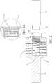
FIGS. 1 ,2 and8 , one resilient connectingmember 10 and one threaded connectingrod 20 of a spring elastic device are illustrated. The resilient connectingmember 10 includes an externally threadedcylinder 17 having tworadial holes 13 at two ends of the threads respectively, anaxial hole 11 having a flat or inclined bottom, an internally threadedportion 15 formed at an open end of theaxial hole 11, and acylindrical connection rod 16 integrally formed with the externally threadedcylinder 17 and projecting out of an end of the externally threadedcylinder 17 opposing the open end of theaxial hole 11. - The threaded connecting
rod 20 includes an externally threadedportion 22 at one end. The externally threadedportion 22 is secured to the internally threadedportion 15 to fasten the threaded connectingrod 20 and the resilient connectingmember 10 together. Two fasteningmembers 30 are put on the threaded connectingrod 20 and theconnection rod 16 respectively. - Each of the threaded connecting
rods 20 and theconnection rod 16 has a diameter of 5.5mm. The threaded connectingrod 20 is solid as shown or hollow in another embodiment. The externally threadedcylinder 17 has a uniform diameter and has a diameter greater than that of the threaded connectingrod 20 or that of theconnection rod 16. Themouth 14 of the internally threadedportion 15 has a diameter gradually increased toward an open end of the externally threadedportion 15. - Referring to
FIGS. 3 ,4 and9 , a spring elastic device in accordance with a first preferred embodiment of the invention is shown. The characteristics of the resilient connectingmembers 10 and the threaded connecting rod 20in the first preferred embodiment are substantially the same as that previously described. In detail, the first preferred embodiment comprises two resilient connectingmembers 10 and a threaded connectingrod 20. Each resilient connectingmember 10 includes an externally threadedcylinder 17 having tworadial holes 13 at two ends of the threads respectively, anaxial hole 11 having a flat or inclined bottom, an internally threadedportion 15 formed at an open end of theaxial hole 11, and acylindrical connection rod 16 integrally formed with the externally threadedcylinder 17 and projecting out of an end of the externally threadedcylinder 17 opposing the open end of theaxial hole 11. - The threaded connecting
rod 20 includes a first externally threadedportion 22 at a first end, and a second externally threadedportion 23 at a second end opposing the first end. The first externally threadedportion 22 is secured to the internally threadedportion 15 of one resilient connectingmember 10, and the second externally threadedportion 23 is secured to the internally threadedportion 15 of the other resilient connectingmember 10 respectively to fasten the threaded connectingrod 20 and the resilient connectingmembers 10 together. Threefastening members 30 are put on the threaded connectingrod 20, theconnection rod 16 of one resilient connectingmember 10, and theconnection rod 16 of the other resilient connectingmember 10 respectively. - Each of the threaded connecting
rod 20 and theconnection rod 16 have a diameter of 5.5mm. The threaded connectingrod 20 is solid as shown or hollow in another embodiment. The externally threadedcylinder 17 has a uniform diameter and has a diameter greater than that of the threaded connectingrod 20 or that of theconnection rod 16. Themouth 14 of the internally threadedportion 15 has a diameter gradually increased toward an open end of the externally threadedportion 15. - Referring to
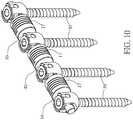
FIGS. 5 ,6 ,7 , and10 , a spring elastic device in accordance with a second preferred embodiment of the invention is shown. The characteristics of the resilient connectingmembers 10 and the threaded connectingrod 20 in the second preferred embodiment are substantially the same as that previously described. In detail, the second preferred embodiment comprises two resilient connectingmembers 10, two threaded connectingrods 20, and a resilient connectingelement 40. Each resilient connectingmember 10 includes an externally threadedcylinder 17 having tworadial holes 13 at two ends of the threads respectively, anaxial hole 11 having a flat or inclined bottom, an internally threadedportion 15 formed at an open end of theaxial hole 11, and acylindrical connection rod 16 integrally formed with the externally threadedcylinder 17 and projecting out of an end of the externally threadedcylinder 17 opposing the open end of theaxial hole 11. - The resilient connecting
element 40 includes an externally threadedcylinder 17 having tworadial holes 13 at two ends of the threads respectively, anaxial channel 12, and two internally threadedportions 15 formed at two open ends of thechannel 12 respectively. - The threaded connecting
rod 20 includes a first externally threadedportion 22 at a first end, and a second externally threadedportion 23 at a second end opposing the first end. The first externally threadedportion 22 is secured to the internally threadedportion 15 of one resilient connectingmember 10 or one internally threadedportion 15 of the resilient connectingelement 40. The second externally threadedportion 23 is secured to the internally threadedportion 15 of the other resilient connectingmember 10 or the other internally threadedportion 15 of the resilient connectingelement 40. As a result, the threaded connectingrods 20, the resilient connectingmembers 10, and the resilient connectingelement 40 are fastened together. Fourfastening members 30 are put on the threaded connectingrods 20, theconnection rod 16 of one resilient connectingmember 10, and theconnection rod 16 of the other resilient connectingmember 10 respectively. - Each of the threaded connecting
rod 20 and theconnection rod 16 has a diameter of 5.5mm. The threaded connectingrod 20 is solid as shown or hollow in another embodiment. The externally threadedcylinder 17 has a uniform diameter and has a diameter greater than that of the threaded connectingrod 20 or that of theconnection rod 16. Themouth 14 of the internally threadedportion 15 of the resilient connecting member 10 (or the resilient connecting element 40) has a diameter gradually increased toward an open end of the externally threadedportion 15. - For extending, a plurality of resilient connecting
elements 40 and more than two threaded connectingrods 20 are required in which each resilient connectingelement 40 is secured to and between two adjacent threaded connectingrods 20, the leftmost threaded connectingrod 20 is secured to and between one resilient connectingmember 10 and the leftmost resilient connectingelement 40, and the rightmost threaded connectingrod 20 is secured to and between the other resilient connectingmember 10 and the rightmost resilient connectingelement 40 by threading in a manner discussed above. - The invention has the following characteristics: No core tube is required, thereby eliminating the problems of core tube breaks or permanent distortion which could make it impossible for the externally threaded
cylinder 17 to return to its original shape. No sealing members are required to seal two ends of the resilient connectingmember 10, thereby eliminating the problem of looseness. The externally threadedcylinder 17 has a uniform diameter and has a diameter greater than that of the threaded connectingrod 20 so that the structural strength of the externally threadedcylinder 17 can be increased. Further, the provision of the tworadial holes 13 at two ends of the threads of the externally threadedcylinder 17 respectively can prevent the externally threadedcylinder 17 from breaking. Theaxial hole 11 or thechannel 12 of the externally threadedcylinder 17 has a smaller diameter so that it is not limited by the length of the threaded connectingrod 20. Further, less restriction is imposed on extension or retraction of the whole. Finally, the threaded connectingrod 20 can be solid or hollow when rigidity is considered.
Claims (7)
- A spinal spring elastic rod device comprising:at least one resilient connecting member (10); andat least one threaded connecting rod (20);wherein each of the at least one resilient connecting member (10) includes an externally threaded cylinder (17) having an axial hole (11) with an internally threaded portion (15) formed at an open end of the axial hole (11) and further comprises a connection rod (16) projecting out of an end of the externally threaded cylinder (17) opposing the open end of the axial hole (11), wherein the connection rod (16) is integrally formed with the externally threaded cylinder (17);
wherein each of the at least one threaded connecting rod (20) includes a first externally threaded portion (22) at a first end; and
wherein the externally threaded cylinder (17) has a diameter greater than that of each of the at least one threaded connecting rod (20),characterized in thattwo resilient connecting members (10) are provided, andeach of the at least one threaded connecting rod (20) includes a second externally threaded portion (23) at a second end opposing the first end, wherein the internally threaded portion (15) of each of the at least one first resilient connecting member (10) is engageable with one of the externally threaded portions (22, 23) respectively. - The spinal spring elastic rod device of claim 1, wherein the axial hole (11) has a bottom which is flat or inclined.
- The spinal spring elastic rod device of claim 1, wherein at least one resilient connecting element (40) is additionally provided, in which the axial hole (11) is through to form an axial channel (12) including two internally threaded portions (15) formed at two open ends thereof respectively.
- The spinal spring elastic rod device of claim 1, wherein each of the threaded connecting rod (20) is solid or hollow.
- The spinal spring elastic rod device of claim 1, wherein the externally threaded cylinder (17) has two radial holes (13) at two ends of the threads thereof respectively.
- The spinal spring elastic rod device of claim 1, wherein a mouth (14) of the internally threaded portion (15) of the axial hole (11) has a diameter gradually increased toward an open end thereof.
- The spinal spring elastic rod device of claim 1, further comprising at least one fastening member (30) each put on the corresponding threaded connecting rod (20).
Priority Applications (1)
| Application Number | Priority Date | Filing Date | Title |
|---|---|---|---|
| EP15170000.2AEP3097877B1 (en) | 2015-05-29 | 2015-05-29 | Spring elastic device that links fixed components on more than two levels of bone |
Applications Claiming Priority (1)
| Application Number | Priority Date | Filing Date | Title |
|---|---|---|---|
| EP15170000.2AEP3097877B1 (en) | 2015-05-29 | 2015-05-29 | Spring elastic device that links fixed components on more than two levels of bone |
Publications (2)
| Publication Number | Publication Date |
|---|---|
| EP3097877A1 EP3097877A1 (en) | 2016-11-30 |
| EP3097877B1true EP3097877B1 (en) | 2019-04-17 |
Family
ID=53298177
Family Applications (1)
| Application Number | Title | Priority Date | Filing Date |
|---|---|---|---|
| EP15170000.2ANot-in-forceEP3097877B1 (en) | 2015-05-29 | 2015-05-29 | Spring elastic device that links fixed components on more than two levels of bone |
Country Status (1)
| Country | Link |
|---|---|
| EP (1) | EP3097877B1 (en) |
Family Cites Families (5)
| Publication number | Priority date | Publication date | Assignee | Title |
|---|---|---|---|---|
| IL162363A0 (en)* | 2001-12-07 | 2005-11-20 | Mathys Medizinaltechnik Ag | Damping element |
| US7833256B2 (en)* | 2004-04-16 | 2010-11-16 | Biedermann Motech Gmbh | Elastic element for the use in a stabilization device for bones and vertebrae and method for the manufacture of such elastic element |
| US20080097431A1 (en)* | 2006-09-22 | 2008-04-24 | Paul Peter Vessa | Flexible spinal stabilization |
| US8080038B2 (en)* | 2007-08-17 | 2011-12-20 | Jmea Corporation | Dynamic stabilization device for spine |
| EP2047810B1 (en)* | 2007-10-11 | 2011-09-28 | BIEDERMANN MOTECH GmbH | Modular rod system for spinal stabilization |
- 2015
- 2015-05-29EPEP15170000.2Apatent/EP3097877B1/ennot_activeNot-in-force
Non-Patent Citations (1)
| Title |
|---|
| None* |
Also Published As
| Publication number | Publication date |
|---|---|
| EP3097877A1 (en) | 2016-11-30 |
Similar Documents
| Publication | Publication Date | Title |
|---|---|---|
| JP5631556B2 (en) | Rod-type implant for spinal stabilization and manufacturing method thereof | |
| US7641673B2 (en) | Flexible linking piece for stabilising the spine | |
| EP2193753B1 (en) | Cord for vertebral fixation having multiple stiffness phases | |
| KR100766580B1 (en) | Rod-like element for application in spinal or trauma surgery, and stabilization device with such a rod-like element | |
| KR20090116633A (en) | Rod-shaped implant for dynamic stability of the spine | |
| DE102010045899B3 (en) | Fan unit with an electric axial fan | |
| CN101647723B (en) | Modular system for the stabilization of the spinal column | |
| CN101442948A (en) | Bone anchor system employing molded coupling member for coupling a bone anchor to a stabilization member and method thereof | |
| JP5208426B2 (en) | Connecting rod with external flexible member | |
| CN101677829B (en) | Flexible rod for fixing vertebrae | |
| US20140200615A1 (en) | Anti-Displacement Coil Spring-Type Spine Stabilization Device | |
| CN101416901A (en) | Rod assembly and modular rod system for spinal stabilization | |
| WO2008094417A3 (en) | Dynamic stabilization member with molded connection | |
| KR20150015393A (en) | Implant for bones or vertebrae with self-constrained flexibility | |
| US10166052B2 (en) | Bone plate with polyaxial locking mechanism | |
| EP3097877B1 (en) | Spring elastic device that links fixed components on more than two levels of bone | |
| CN101938949B (en) | Dynamic stabilisation member for vertebrae | |
| TWI634881B (en) | Femoral stem with cushion | |
| CN204468242U (en) | A helical elastic device that connects fixation elements of more than two bones | |
| CN107428219A (en) | The method of bearing element and the stabilizer for manufacturing vehicle | |
| EP3016623A1 (en) | Tampon applicator and method for its assembly | |
| CN105102865B (en) | Dust cover | |
| EP1563260A1 (en) | Housing with reduced thermal conduction for a measuring instrument | |
| EP2229902A2 (en) | Transpedicular spinal stabilizer | |
| US9169919B2 (en) | Assembly of knob and lever |
Legal Events
| Date | Code | Title | Description |
|---|---|---|---|
| PUAI | Public reference made under article 153(3) epc to a published international application that has entered the european phase | Free format text:ORIGINAL CODE: 0009012 | |
| 17P | Request for examination filed | Effective date:20150904 | |
| AK | Designated contracting states | Kind code of ref document:A1 Designated state(s):AL AT BE BG CH CY CZ DE DK EE ES FI FR GB GR HR HU IE IS IT LI LT LU LV MC MK MT NL NO PL PT RO RS SE SI SK SM TR | |
| AX | Request for extension of the european patent | Extension state:BA ME | |
| GRAP | Despatch of communication of intention to grant a patent | Free format text:ORIGINAL CODE: EPIDOSNIGR1 | |
| STAA | Information on the status of an ep patent application or granted ep patent | Free format text:STATUS: GRANT OF PATENT IS INTENDED | |
| INTG | Intention to grant announced | Effective date:20181026 | |
| GRAS | Grant fee paid | Free format text:ORIGINAL CODE: EPIDOSNIGR3 | |
| GRAA | (expected) grant | Free format text:ORIGINAL CODE: 0009210 | |
| STAA | Information on the status of an ep patent application or granted ep patent | Free format text:STATUS: THE PATENT HAS BEEN GRANTED | |
| AK | Designated contracting states | Kind code of ref document:B1 Designated state(s):AL AT BE BG CH CY CZ DE DK EE ES FI FR GB GR HR HU IE IS IT LI LT LU LV MC MK MT NL NO PL PT RO RS SE SI SK SM TR | |
| REG | Reference to a national code | Ref country code:GB Ref legal event code:FG4D | |
| REG | Reference to a national code | Ref country code:CH Ref legal event code:EP | |
| REG | Reference to a national code | Ref country code:DE Ref legal event code:R096 Ref document number:602015028342 Country of ref document:DE | |
| REG | Reference to a national code | Ref country code:AT Ref legal event code:REF Ref document number:1120713 Country of ref document:AT Kind code of ref document:T Effective date:20190515 Ref country code:IE Ref legal event code:FG4D | |
| REG | Reference to a national code | Ref country code:NL Ref legal event code:MP Effective date:20190417 | |
| REG | Reference to a national code | Ref country code:LT Ref legal event code:MG4D | |
| PG25 | Lapsed in a contracting state [announced via postgrant information from national office to epo] | Ref country code:NL Free format text:LAPSE BECAUSE OF FAILURE TO SUBMIT A TRANSLATION OF THE DESCRIPTION OR TO PAY THE FEE WITHIN THE PRESCRIBED TIME-LIMIT Effective date:20190417 | |
| PG25 | Lapsed in a contracting state [announced via postgrant information from national office to epo] | Ref country code:AL Free format text:LAPSE BECAUSE OF FAILURE TO SUBMIT A TRANSLATION OF THE DESCRIPTION OR TO PAY THE FEE WITHIN THE PRESCRIBED TIME-LIMIT Effective date:20190417 Ref country code:PT Free format text:LAPSE BECAUSE OF FAILURE TO SUBMIT A TRANSLATION OF THE DESCRIPTION OR TO PAY THE FEE WITHIN THE PRESCRIBED TIME-LIMIT Effective date:20190817 Ref country code:ES Free format text:LAPSE BECAUSE OF FAILURE TO SUBMIT A TRANSLATION OF THE DESCRIPTION OR TO PAY THE FEE WITHIN THE PRESCRIBED TIME-LIMIT Effective date:20190417 Ref country code:SE Free format text:LAPSE BECAUSE OF FAILURE TO SUBMIT A TRANSLATION OF THE DESCRIPTION OR TO PAY THE FEE WITHIN THE PRESCRIBED TIME-LIMIT Effective date:20190417 Ref country code:HR Free format text:LAPSE BECAUSE OF FAILURE TO SUBMIT A TRANSLATION OF THE DESCRIPTION OR TO PAY THE FEE WITHIN THE PRESCRIBED TIME-LIMIT Effective date:20190417 Ref country code:NO Free format text:LAPSE BECAUSE OF FAILURE TO SUBMIT A TRANSLATION OF THE DESCRIPTION OR TO PAY THE FEE WITHIN THE PRESCRIBED TIME-LIMIT Effective date:20190717 Ref country code:LT Free format text:LAPSE BECAUSE OF FAILURE TO SUBMIT A TRANSLATION OF THE DESCRIPTION OR TO PAY THE FEE WITHIN THE PRESCRIBED TIME-LIMIT Effective date:20190417 Ref country code:FI Free format text:LAPSE BECAUSE OF FAILURE TO SUBMIT A TRANSLATION OF THE DESCRIPTION OR TO PAY THE FEE WITHIN THE PRESCRIBED TIME-LIMIT Effective date:20190417 | |
| PG25 | Lapsed in a contracting state [announced via postgrant information from national office to epo] | Ref country code:PL Free format text:LAPSE BECAUSE OF FAILURE TO SUBMIT A TRANSLATION OF THE DESCRIPTION OR TO PAY THE FEE WITHIN THE PRESCRIBED TIME-LIMIT Effective date:20190417 Ref country code:LV Free format text:LAPSE BECAUSE OF FAILURE TO SUBMIT A TRANSLATION OF THE DESCRIPTION OR TO PAY THE FEE WITHIN THE PRESCRIBED TIME-LIMIT Effective date:20190417 Ref country code:BG Free format text:LAPSE BECAUSE OF FAILURE TO SUBMIT A TRANSLATION OF THE DESCRIPTION OR TO PAY THE FEE WITHIN THE PRESCRIBED TIME-LIMIT Effective date:20190717 Ref country code:RS Free format text:LAPSE BECAUSE OF FAILURE TO SUBMIT A TRANSLATION OF THE DESCRIPTION OR TO PAY THE FEE WITHIN THE PRESCRIBED TIME-LIMIT Effective date:20190417 Ref country code:GR Free format text:LAPSE BECAUSE OF FAILURE TO SUBMIT A TRANSLATION OF THE DESCRIPTION OR TO PAY THE FEE WITHIN THE PRESCRIBED TIME-LIMIT Effective date:20190718 | |
| REG | Reference to a national code | Ref country code:DE Ref legal event code:R119 Ref document number:602015028342 Country of ref document:DE | |
| REG | Reference to a national code | Ref country code:AT Ref legal event code:MK05 Ref document number:1120713 Country of ref document:AT Kind code of ref document:T Effective date:20190417 | |
| REG | Reference to a national code | Ref country code:CH Ref legal event code:PL | |
| PG25 | Lapsed in a contracting state [announced via postgrant information from national office to epo] | Ref country code:IS Free format text:LAPSE BECAUSE OF FAILURE TO SUBMIT A TRANSLATION OF THE DESCRIPTION OR TO PAY THE FEE WITHIN THE PRESCRIBED TIME-LIMIT Effective date:20190817 | |
| PG25 | Lapsed in a contracting state [announced via postgrant information from national office to epo] | Ref country code:LI Free format text:LAPSE BECAUSE OF NON-PAYMENT OF DUE FEES Effective date:20190531 Ref country code:MC Free format text:LAPSE BECAUSE OF FAILURE TO SUBMIT A TRANSLATION OF THE DESCRIPTION OR TO PAY THE FEE WITHIN THE PRESCRIBED TIME-LIMIT Effective date:20190417 Ref country code:AT Free format text:LAPSE BECAUSE OF FAILURE TO SUBMIT A TRANSLATION OF THE DESCRIPTION OR TO PAY THE FEE WITHIN THE PRESCRIBED TIME-LIMIT Effective date:20190417 Ref country code:CH Free format text:LAPSE BECAUSE OF NON-PAYMENT OF DUE FEES Effective date:20190531 Ref country code:DK Free format text:LAPSE BECAUSE OF FAILURE TO SUBMIT A TRANSLATION OF THE DESCRIPTION OR TO PAY THE FEE WITHIN THE PRESCRIBED TIME-LIMIT Effective date:20190417 Ref country code:SK Free format text:LAPSE BECAUSE OF FAILURE TO SUBMIT A TRANSLATION OF THE DESCRIPTION OR TO PAY THE FEE WITHIN THE PRESCRIBED TIME-LIMIT Effective date:20190417 Ref country code:EE Free format text:LAPSE BECAUSE OF FAILURE TO SUBMIT A TRANSLATION OF THE DESCRIPTION OR TO PAY THE FEE WITHIN THE PRESCRIBED TIME-LIMIT Effective date:20190417 Ref country code:RO Free format text:LAPSE BECAUSE OF FAILURE TO SUBMIT A TRANSLATION OF THE DESCRIPTION OR TO PAY THE FEE WITHIN THE PRESCRIBED TIME-LIMIT Effective date:20190417 Ref country code:CZ Free format text:LAPSE BECAUSE OF FAILURE TO SUBMIT A TRANSLATION OF THE DESCRIPTION OR TO PAY THE FEE WITHIN THE PRESCRIBED TIME-LIMIT Effective date:20190417 | |
| REG | Reference to a national code | Ref country code:BE Ref legal event code:MM Effective date:20190531 | |
| PLBE | No opposition filed within time limit | Free format text:ORIGINAL CODE: 0009261 | |
| STAA | Information on the status of an ep patent application or granted ep patent | Free format text:STATUS: NO OPPOSITION FILED WITHIN TIME LIMIT | |
| PG25 | Lapsed in a contracting state [announced via postgrant information from national office to epo] | Ref country code:LU Free format text:LAPSE BECAUSE OF NON-PAYMENT OF DUE FEES Effective date:20190529 Ref country code:IT Free format text:LAPSE BECAUSE OF FAILURE TO SUBMIT A TRANSLATION OF THE DESCRIPTION OR TO PAY THE FEE WITHIN THE PRESCRIBED TIME-LIMIT Effective date:20190417 Ref country code:SM Free format text:LAPSE BECAUSE OF FAILURE TO SUBMIT A TRANSLATION OF THE DESCRIPTION OR TO PAY THE FEE WITHIN THE PRESCRIBED TIME-LIMIT Effective date:20190417 | |
| 26N | No opposition filed | Effective date:20200120 | |
| GBPC | Gb: european patent ceased through non-payment of renewal fee | Effective date:20190717 | |
| PG25 | Lapsed in a contracting state [announced via postgrant information from national office to epo] | Ref country code:TR Free format text:LAPSE BECAUSE OF FAILURE TO SUBMIT A TRANSLATION OF THE DESCRIPTION OR TO PAY THE FEE WITHIN THE PRESCRIBED TIME-LIMIT Effective date:20190417 | |
| PG25 | Lapsed in a contracting state [announced via postgrant information from national office to epo] | Ref country code:DE Free format text:LAPSE BECAUSE OF NON-PAYMENT OF DUE FEES Effective date:20191203 Ref country code:IE Free format text:LAPSE BECAUSE OF NON-PAYMENT OF DUE FEES Effective date:20190529 Ref country code:GB Free format text:LAPSE BECAUSE OF NON-PAYMENT OF DUE FEES Effective date:20190717 | |
| PG25 | Lapsed in a contracting state [announced via postgrant information from national office to epo] | Ref country code:SI Free format text:LAPSE BECAUSE OF FAILURE TO SUBMIT A TRANSLATION OF THE DESCRIPTION OR TO PAY THE FEE WITHIN THE PRESCRIBED TIME-LIMIT Effective date:20190417 Ref country code:BE Free format text:LAPSE BECAUSE OF NON-PAYMENT OF DUE FEES Effective date:20190531 | |
| PG25 | Lapsed in a contracting state [announced via postgrant information from national office to epo] | Ref country code:FR Free format text:LAPSE BECAUSE OF NON-PAYMENT OF DUE FEES Effective date:20190617 | |
| PG25 | Lapsed in a contracting state [announced via postgrant information from national office to epo] | Ref country code:CY Free format text:LAPSE BECAUSE OF FAILURE TO SUBMIT A TRANSLATION OF THE DESCRIPTION OR TO PAY THE FEE WITHIN THE PRESCRIBED TIME-LIMIT Effective date:20190417 | |
| PG25 | Lapsed in a contracting state [announced via postgrant information from national office to epo] | Ref country code:MT Free format text:LAPSE BECAUSE OF FAILURE TO SUBMIT A TRANSLATION OF THE DESCRIPTION OR TO PAY THE FEE WITHIN THE PRESCRIBED TIME-LIMIT Effective date:20190417 Ref country code:HU Free format text:LAPSE BECAUSE OF FAILURE TO SUBMIT A TRANSLATION OF THE DESCRIPTION OR TO PAY THE FEE WITHIN THE PRESCRIBED TIME-LIMIT; INVALID AB INITIO Effective date:20150529 | |
| PG25 | Lapsed in a contracting state [announced via postgrant information from national office to epo] | Ref country code:MK Free format text:LAPSE BECAUSE OF FAILURE TO SUBMIT A TRANSLATION OF THE DESCRIPTION OR TO PAY THE FEE WITHIN THE PRESCRIBED TIME-LIMIT Effective date:20190417 |