EP3096704B1 - Sterile drape and adapter for covering a robotic surgical arm and preventing contamination of a sterile field - Google Patents
Sterile drape and adapter for covering a robotic surgical arm and preventing contamination of a sterile fieldDownload PDFInfo
- Publication number
- EP3096704B1 EP3096704B1EP15700759.2AEP15700759AEP3096704B1EP 3096704 B1EP3096704 B1EP 3096704B1EP 15700759 AEP15700759 AEP 15700759AEP 3096704 B1EP3096704 B1EP 3096704B1
- Authority
- EP
- European Patent Office
- Prior art keywords
- sterile
- drape
- sterile drape
- surgical
- robotic arm
- Prior art date
- Legal status (The legal status is an assumption and is not a legal conclusion. Google has not performed a legal analysis and makes no representation as to the accuracy of the status listed.)
- Active
Links
Images


Classifications
- A—HUMAN NECESSITIES
- A61—MEDICAL OR VETERINARY SCIENCE; HYGIENE
- A61B—DIAGNOSIS; SURGERY; IDENTIFICATION
- A61B46/00—Surgical drapes
- A61B46/20—Surgical drapes specially adapted for patients
- A61B46/27—Surgical drapes specially adapted for patients tubular, e.g. for arms or legs
- A—HUMAN NECESSITIES
- A61—MEDICAL OR VETERINARY SCIENCE; HYGIENE
- A61B—DIAGNOSIS; SURGERY; IDENTIFICATION
- A61B46/00—Surgical drapes
- A61B46/10—Surgical drapes specially adapted for instruments, e.g. microscopes
- A—HUMAN NECESSITIES
- A61—MEDICAL OR VETERINARY SCIENCE; HYGIENE
- A61B—DIAGNOSIS; SURGERY; IDENTIFICATION
- A61B34/00—Computer-aided surgery; Manipulators or robots specially adapted for use in surgery
- A61B34/30—Surgical robots
Definitions
- Robotic-assisted surgical systemshave been developed to improve surgical precision and enable the implementation of new surgical procedures.
- robotic systemshave been developed to sense a surgeon's hand movements and translate them to scaled-down micro-movements and filter out unintentional tremors for precise microsurgical techniques in organ transplants, reconstructions, and minimally invasive surgeries.
- Other robotic systemsare directed to telemanipulation of surgical tools such that the surgeon does not have to be present in the operating room, thereby facilitating remote surgery.
- Feedback-controlled robotic systemshave also been developed to provide smoother manipulation of a surgical tool during a procedure than could be achieved by an unaided surgeon.
- WO 2013/160239 A1discloses a sterile drape for covering a surgical robot arm.
- US 4799779 Adiscloses a surgical drape for covering a microscope having side sleeves.
- Common spinal surgical proceduresinclude a discectomy for removal of all or part of a disk, a foraminotomy for widening of the opening where nerve roots leave the spinal column, a laminectomy for removal of the lamina or bone spurs in the back, and spinal fusion for fusing of two vertebrae or vertebral segments together to eliminate pain caused by movement of the vertebrae.
- a surgeonjudges a drill trajectory for subsequent screw placement on the basis of pre-operative CT scans.
- Other manual methodswhich do not involve usage of the pre-operative CT scans, such as fluoroscopy, 3D fluoroscopy or natural landmark-based, may be used to determine the trajectory for preparing holes in bone prior to placement of the screws.
- the surgeonholds the drill in his hand while drilling, and fluoroscopic images are obtained to verify if the trajectory is correct.
- Some surgical techniquesinvolve usage of different tools, such as a pedicle finder or K-wires. Such procedures rely strongly on the expertise of the surgeon, and there is significant variation in success rate among different surgeons. Screw misplacement is a common problem in such surgical procedures.
- Image-guided spinal surgeriesinvolve optical tracking to aid in screw placement.
- surgical toolscan be inaccurately positioned despite virtual tracking.
- a surgeonis required to coordinate his real-world, manual manipulation of surgical tools using images displayed on a two dimensional screen.
- Such procedurescan be non-intuitive and require training, since the surgeon's eye must constantly scan both the surgical site and the screen to confirm alignment.
- procedural errorcan result in registration inaccuracy of the image-guiding system, rendering it useless, or even misleading.
- Described hereinare a sterile drape and adapter for use with a robotic surgical system, for example, during spinal surgery.
- the inventionis defined by claim 1. Further embodiments of the invention are defined by the dependent claims.
- the sterile drape and adaptercover a robotic surgical arm and prevent contamination of a sterile field.
- the sterile drapemay attached to the robotic arm via a sterile adapter that ensures the drape is tightly stretched over the tool holder and robot interface to provide a structure that provides for repeatable and rigid positioning of the sterile drape. Tightly stretching the drape over the sterile adapter and tightening the tool holder to the robotic arm using, for example, a tightening screw, reduces the likelihood of folds in the drape between the told holder and robot interface. Thus, errors caused by inaccurate positioning of the tool holder relative to the robot interface are minimized.
- a hermetically sealed zoneis formed by the tool holder, sterile adapter, and robotic arm.
- the hermetically sealed zonecontains the perforated sections of the sterile drape, thus ensuring the robotic system may be used in a sterile environment even after the tool support is attached to the robotic arm.
- the disclosed technologyincludes a sterile drape for covering a surgical robotic arm and preventing contamination of a sterile field.
- the sterile drapeincludes a flexible covering with a sterile outer surface. The covering may be at least partially conformable to a surgical robotic arm.
- the sterile drapemay include an embedded connector configured (e.g., positioned on the flexible covering and sized) to permit electrical contact between the surgical robotic arm (e.g., an actuator of the robotic arm) and a sterile manipulator (e.g., sterile handle) of the robotic arm when the sterile manipulator is separated from the surgical robotic arm by the flexible covering.
- the sterile drapeis disposable (e.g., a single-use product).
- the disclosed technologyincludes a rigid or semi-rigid sterile adapter (e.g., made from a hard plastic, a polymer, or a composite material) for securing a sterile drape over a surgical robotic arm to prevent contamination of a sterile field.
- the sterile adapterincludes a rigid or semi-rigid collar (e.g., ring) configured to mount (e.g., snap-mount) onto an interface of the surgical robotic arm.
- the sterile adaptermay include a rigid or semi-rigid body extending from the collar and shaped to conform to a portion of the surgical robotic arm to tightly secure a flexible drape in place (e.g., with no folds) over the portion of the surgical robotic arm when the drape is attached to the adapter.
- the sterile adapteris disposable (e.g. a single-use product).
- the disclosed technologyincludes a sterile drape that is attached (e.g., glued or welded) to a sterile adapter.
- the sterile adapterthat ensures the drape is tightly stretched over the tool holder and robot interface to protect the robotic arm and mobile cart from contaminating the sterile field, and provides a structure that provides for repeatable and rigid positioning of the sterile drape.
- the disclosed technologyincludes a sterile drape for covering a surgical robotic arm and preventing contamination of a sterile field.
- the sterile drapeincludes, in certain embodiments, a flexible covering with a sterile outer surface and a sterile drape sleeve configured to receive an electrical plug therethrough, said covering being at least partially conformable to a surgical robotic arm.
- the sterile drape sleeveis configured to be sealed around a portion of the electrical plug using a sterile adhesive tape.
- the sterile drape sleevein certain embodiments, is configured to surround at least a portion of a connector of the surgical robotic arm and extend outwardly from the connector.
- the connectoris configured to permit electrical contact between the surgical robotic arm (e.g., an actuator of the robotic arm) and a sterile manipulator (e.g., sterile handle) of the robotic arm when the sterile manipulator is separated from the surgical robotic arm by the flexible covering.
- the surgical robotic arme.g., an actuator of the robotic arm
- a sterile manipulatore.g., sterile handle
- the sterile drapeis configured to be attached to the sterile drape before draping the robotic surgical arm.
- the connectoris configured to receive the electrical plug after the electrical plug is passed through the sterile drape sleeve.
- the connectoris configured to receive the electrical plug after (i) the electrical plug is passed through the sterile drape sleeve and (ii) the sterile drape sleeve is sealed around a portion of the electrical plug using a sterile adhesive tape.
- the sterile drapeis configured to be attached to the sterile drape after draping the robotic surgical arm.
- the sterile drapecomprises a drape stiffener configured to assist in passing the electrical plug through the sterile drape sleeve.
- the drape stiffeneris made of a semi-rigid material (e.g., rubber, adhesive tape, tape reinforcement).
- the drape stiffeneris made of a rigid material (e.g., plastic).
- the drape stiffeneris integrated in the sterile drape.
- the drape stiffeneris removable.
- the drape stiffeneris configured to be inserted before the sterile drape is applied to the robot surgical arm.
- the drape stiffeneris configured to be inserted after the sterile drape is applied to the robot surgical arm. In certain embodiments, the drape stiffener is configured to be removed after the sterile drape is applied to the robot surgical arm. In certain embodiments, the drape stiffener is configured to be removed after (i) the sterile drape is applied to the robot surgical arm and (ii) the sterile drape sleeve is sealed around a portion of the electrical plug using a sterile adhesive tape.
- the disclosed technologyincludes a sterile drape for covering a surgical robotic arm and preventing contamination of a sterile field.
- the sterile drapeincludes a flexible covering with a sterile outer surface, said covering being at least partially conformable to a surgical robotic arm.
- the flexible coveringincludes a drape opening that is configured to be contained within a sealed chamber formed by the surgical robotic arm, a sterile adapter, and a surgical tool holder such that a fastening system may pass through the chamber and the drape opening when the surgical instrument holder is coupled to the surgical robotic arm.
- the fastening systemcomprises one or more positioning elements that extend from the surgical robotic arm and engage one or more surgical instrument holder positioning members.
- the one or more positioning elementsare one or more pegs.
- the one or more pegsare configured to extend from the robotic arm and engage one or more holes in the surgical instrument holder.
- the fastening systemcomprises a fastening member configured to securely attach the surgical instrument holder to the surgical robotic arm.
- the fastening memberis a member selected from the group consisting of a bolt, nut, screw, and one or more electro magnets.
- the disclosed technologyincludes a sterile drape for covering a surgical robotic arm and preventing contamination of a sterile field.
- the sterile drapeincludes a flexible covering with a sterile outer surface, said covering being at least partially conformable to a surgical robotic arm; and an embedded connector configured (e.g., positioned on the flexible covering and sized) to permit electrical contact between the surgical robotic arm (e.g., an actuator of the robotic arm) and a sterile manipulator (e.g., sterile handle) of the robotic arm when the sterile manipulator is separated from the surgical robotic arm by the flexible covering.
- the surgical robotic arme.g., an actuator of the robotic arm
- a sterile manipulatore.g., sterile handle
- the disclosed technologyincludes a rigid or semi-rigid sterile adapter (e.g., made from a hard plastic, a polymer, or a composite material) for securing a sterile drape over a surgical robotic arm to prevent contamination of a sterile field.
- a rigid or semi-rigid sterile adaptere.g., made from a hard plastic, a polymer, or a composite material
- the sterile adapterincludes a rigid or semi-rigid collar (e.g., ring) configured to mount (e.g., snap-mount) onto an interface of the surgical robotic arm; and a rigid or semi-rigid body extending from the collar and shaped to conform to a portion of the surgical robotic arm to tightly secure a flexible drape in place (e.g., with no folds) over the portion of the surgical robotic arm when the drape is attached to the adapter.
- a rigid or semi-rigid collare.g., ring
- mounte.g., snap-mount
- a rigid or semi-rigid bodyextending from the collar and shaped to conform to a portion of the surgical robotic arm to tightly secure a flexible drape in place (e.g., with no folds) over the portion of the surgical robotic arm when the drape is attached to the adapter.
- the sterile drapeis disposable (e.g., a single-use product).
- the sterile adapteris disposable (e.g. a single-use product).
- the disclosed technologyincludes an apparatus that includes a sterile drape and a sterile adapter.
- the apparatusis disposable (e.g., a single-use product).
- the disclosed technologyincludes a robotic surgical system for performing surgery.
- the systemincludes a robotic arm with an end effector, a surgical instrument holder configured to securely hold the surgical instrument, and one or more positioning elements configured to provide accurate and repeatable positioning of the surgical instrument holder in reference to the robotic arm; a manipulator configured to allow robotically-assisted or unassisted positioning and/or movement of the surgical instrument by a user with at least four degrees of freedom to align an axis defined by the surgical instrument at a desired trajectory in relation to a patient situation; a sterile drape configured to protect the robotic arm from contaminating a sterile field.
- the sterile drapeincludes a drape connector configured to electrically couple, through the sterile drape, the manipulator to an electrical system of the robotic surgical system covered by the sterile drape, and the one or more positioning elements pass through the sterile drape.
- a sterile adapteris configured to attach to the robotic arm via a robotic interface and tightly stretch the sterile drape to assure repeatable and rigid positioning of the sterile drape.
- the surgical instrument holderis attached to the robotic arm using a fastening system configured to pass through the sterile adapter and the sterile drape.
- the surgical instrumentcomprises a surgical instrument guide configured to hold and/or restrict movement of a second surgical instrument there through.
- the second surgical instrumentis a member selected from the group consisting of: a drill bit, tap, screw driver, and awl.
- the second surgical instrumentis a drill bit and the surgical instrument guide is a drill guide.
- the robotic surgical systemis for use in spinal surgery.
- the one or more positioning elementsextend from the robotic arm and engage one or more surgical instrument holder positioning members. In certain embodiments, the one or more positioning elements are one or more pegs. In certain embodiments, the one or more pegs are configured to extend from the robotic arm and engage one or more holes in the surgical instrument holder. In certain embodiments, the one or more positioning elements are configured to pass through the sterile drape.
- the systemincludes a mobile cart configured to transport the robotic surgical system, wherein the sterile drape is configured to protect the mobile cart from contaminating a sterile field.
- the sterile drapecomprises a first sterile drape to protect the robotic arm and a second sterile drape to protect the mobile cart.
- the sterile drapecomprises printed marks configured to assist in proper draping procedure.
- the systemincludes one or more holding stripes configured to hold the sterile drape (e.g., securely in place). In certain embodiments, the one or more holding stripes secure a portion of the sterile drape to the robotic arm.
- the systemincludes a suppression system configured to remove air from under the sterile drape.
- the suppression systemincludes at least one member selected from the group consisting of a ventilator and a suction device that pumps out the air from under the sterile drape.
- the sterile handleis coupled to a handle connector via a cable and the handle connector is configured to electrically connect to the drape connector.
- the electrical system of the robotic surgical systemis coupled to a robot connector and the robot connector is configured to electrically connect to the drape connector.
- the robot connectorelectrically couples the drape connector to the robot connector.
- the sterile adaptercomprises one or more tabs configured to attach to the robotic arm.
- the one or more tabsclick onto an interface on the robotic arm.
- the one or more tabscomprise four tabs.
- the sterile drapeis glued or welded to the sterile adapter.
- the sterile drapepasses between the surgical instrument tool holder and the robotic interface. In certain embodiments, the sterile drape is tightly stretched between the surgical instrument tool holder and the robotic interface. In certain embodiments, the surgical instrument holder is a non-conductive material.
- the disclosed technologyincludes an exemplary not claimed method of performing surgery with a robotic surgical system.
- the methodincludes attaching a sterile adapter to a robotic arm of a robotic surgical system via a robotic interface, wherein: a sterile drape is coupled to the sterile adapter and is configured to protect the robotic arm from contaminating a sterile field, and the sterile adapter is configured to tightly stretch the sterile drape to assure repeatable and rigid positioning of the sterile drape; covering a portion of the robotic surgical system with the sterile drape; connecting a drape connector to a handle connector and a robot connector, wherein the sterile drape comprises the drape connector and the drape connector is configured to electrically couple the handle connector to the robot connector; securing a portion of the sterile drape to the robotic arm via one or more holding stripes; attaching the surgical tool holder to the robotic arm using a fastening system configured to pass through the sterile adapter and the sterile drape, wherein: the surgical tool holder is
- the exemplary methodincludes maneuvering the second surgical instrument through the surgical instrument guide. In certain embodiments, the method includes maneuvering a drill bit through a drill bit guide.
- the sterile drapeis configured to cover the robotic arm and mobile cart and protect the robotic arm and mobile cart from contaminating a sterile field.
- the fastening systemgoes through the sterile drape.
- the one or more holding stripeswrap around the robotic arm.
- a suppression systemconfigured to remove air from under the sterile drape. In certain embodiments, the suppression system comprises at least one member selected from the group consisting of a ventilator and a suction device that pumps out the air from under the sterile drape.
- stabilizing the mobile cartincludes extracting one or more rigid legs on the mobile cart such that the mobile cart rests on the one or more rigid legs of the mobile cart. In certain embodiments, stabilizing the mobile cart comprises retracting one or more wheels on the mobile cart such that the mobile cart rests on one or more rigid legs of the mobile cart.
- the methodincludes, prior to maneuvering the robotic arm to a desired position, obtaining or accessing a CT scan, 3D CT scan, fluoroscopy, 3D fluoroscopy, or natural landmark-based image of the patient situation.
- the desired trajectoryis a desired path of the surgical tool.
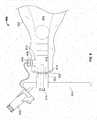
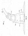
- FIG. 1illustrates an example robotic surgical system 100.
- one or more surgeons, surgical assistants, surgical technologists and/or other techniciansperform an operation on a patient using a robotic-assisted surgical system 100.
- the robotic surgical system 100may be transported in and out of an operating room using a mobile cart 104. Accordingly, the robotic surgical system 100, including the mobile cart 104, must be sterilized when used in the operating room.
- the systemmay be sterilized by applying a sterile drape 102 to a portion of the system 100, including at least part of the robotic arm 106 and the mobile cart 104.
- the sterile drape 102may consist of a single drape or several pieces, such as sterile cover 102a for covering the robotic arm 106 and sterile drape 102b for covering the mobile cart 104.
- the sterile drape 102is attached (e.g., glued or welded) to a sterile adapter 108.
- the sterile adapter 108may be attached (e.g., clipped) to an interface on the robotic arm 106.
- the sterile adapter 108ensures the drape 102 is tightly stretched over the interface between the tool holder 110 and robot interface to protect the robotic arm 106 and mobile cart 104 from contaminating the sterile field, and provides a structure that provides for repeatable and rigid positioning of the sterile drape 102.
- a sterile tool holder 110may be connected to the robotic arm 106 through the sterile drape 102.
- the tool holder 110may hold sterile surgical instruments (e.g., tool guide 112) and may be coupled to a navigation marker 114.
- sterile surgical instrumentse.g., tool guide 112
- a navigation marker 114e.g., a navigation marker 114.
- a band 116may be provided around the force sensor 120 mounted on the robotic arm.
- Band 116may provide force sensor 120 protection.
- the force sensormeasures forces applied to all parts attached to it (e.g., sterile adapter, tool guide, optical marker, etc.).
- the sterile drapeis attached to the sterile adapter and when, for example, the robotic arm moves or somebody touches the drape, the drape can tear on the force sensor and/or impact the measurements by the force sensor. By adding force sensor protection (e.g., band 116), this problem is mitigated.
- the drape 102may also be secured around the robotic arm 106 using holding stripes 118.
- the a suppression systemsuch as a pump, ventilator, or other suction device may be used to remove air from inside the device.
- the holding strips 118are used in combination with a suppression system.
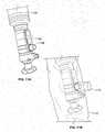
- FIG. 2is an illustration of an example sterile adapter 200 for use with a robotic surgical system.
- the sterile adapter 200may be a disposable (e.g. a single-use product). For example, a new sterile adapter 200 may be used for every surgical procedure.
- the sterile adapter 200is a rigid or semi-rigid device. It may be made from a hard plastic, polymer, or a composite material.
- the sterile adapter 200secures a drape over a surgical robotic arm to prevent contamination of a sterile field.
- the sterile adapter 200may include a rigid or semi-rigid collar 202 (e.g., ring or a hollow cylindrical structure) configured to mount (e.g., snap-mount) onto an interface of the surgical robotic arm.
- the sterile adapter 200may include a rigid or semi-rigid body 204 extending from the collar and shaped to conform to a portion of the surgical robotic arm to tightly secure a flexible drape in place (e.g., with no folds) over the portion of the surgical robotic arm when the drape is attached to the adapter 200.
- the body 204is one or more tabs 204a-d (e.g., 3, 4, 5, 6, 7, or 8 tabs) that engage an interface on the robot.
- the tabsmay "click" into the interface to provide easy and secure mounting of the sterile adapter, and hence sterile drape, on the robot.
- the sterile drapemay be glued or welded to the sterile adapter 200 (e.g., during manufacturing).
- the adapter 200ensures that the drape is tightly stretched over the tool holder and robot interface to provide repeatable and rigid positioning of the tool holder relative to the robotic arm.
- FIG. 3is an illustration of an sterile drape 304 coupled, via glue or welding, to a sterile adapter 302.
- the sterile drape 304is glued or welded to the sterile adapter 302. After the welding/gluing dries the part of the drape inside the sterile adapter 302 is stretched. This portion of the drape (i.e., the stretched portion inside of the sterile adapter 302 is the only part of the drape that is located between the tool holder and the robotic arm. As shown in FIG. 3 , the sterile drape 304 is tightly stretched over the opening of the sterile adapter 302. When the sterile adapter 302 is attached to the robotic arm (e.g., clicked into the interface on the robotic arm), the end of the robotic arm will be covered by the sterile drape 304 that is stretched over the opening of the sterile adapter 302. As described below, in some implementations, positioning elements and a tightening screw will protrude through the opening of the sterile adapter and piece the sterile drape when the tool support is applied to the robotic arm.
- FIG. 4A-Billustrate an example sterile adapter 400 applied to a robotic surgical system 450.
- Tabs/clips 402engage grooves 404 on the interface 406 of the robot arm.
- the tabs/clips 402include a single tab/clip. The tabs/clips may "click" to engage the groove(s) 402 on the robot interface 406.
- the tool holder 410may be attached to the robot.
- the tool holder 410may include one or more positioning members 412 (e.g., pins or pegs) that engage one or more holes 414 in the robot interface 406 to provide accurate/repeatable positioning of the tool holder in reference to the robot interface.
- the one or more positioning members 412may pierce the sterile drape 416 to engage the hole(s) 414.
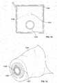
- the sterile drape 1404includes a drape opening 1406 that is large enough to allow passage of the positioning pins without puncturing the drape.
- the sterile adapter 1402stretches the drape to avoid folds as described above.
- the drape opening 1406is configured to be located inside the sterile adapter 1402 (i.e., the sterile drape does is not on the inside of the sterile adapter).
- a dust cover 1408may be placed over the drape opening 1406 and attached to the drape 1404.
- the dust cover 1408may be configured to attach to the drape 1404 using an adhesive material.
- the dust cover 1408may be removed after the drape 1404 is installed, for example, on the robotic surgical arm, thus reducing contamination of the sterile field. After the sterile drape 1404 is installed, the dust cover 1408 may be removed and the tool holder may be installed.
- the position member(s) 412may be uniquely shaped to ensure that the tool holder 410 is always appropriately positioned/ oriented on the robot interface 406. In some implementations, the positioning member(s) is/are located on the robot interface 406 and the hole(s) 414 is/are located on the tool holder 410 (i.e., opposite of what is shown in FIG. 4B ).
- the tool holder 410may be securely attached to the robot using a tightening screw 408.
- the tightening screw 408may be tightened using a torque wrench or other torque-limited tool.
- the wrenchis disposable and/or destroyed after achieving a certain torque.
- the tightening screwis tightened, it pieces the sterile drape 416 and engages threads on the robot interface 406.
- the sterile drape 416is tightly stretched over the sterile adapter 400, thus when the tightening screw 408 is tightened to the appropriate torque setting, only a single layer of the sterile adapter 400 material is between the tool holder 410 and the robot interface 406.
- the sterile adapter 408is easy to perforate (e.g., by the position member(s) and the tightening screw) when the sterile tool holder 410 is installed.
- the a bolt or nutis used to securely attached the tool holder 410 to the robot.
- electromagnet(s)is/are used to securely attached the tool holder 410 to the robot.
- the tightening screw 408 and the positioning member(s) 414protrude through the sterile drape 416.
- these perforationsare in the inner space formed by the robot interface 406, the sterile adapter 400, and the tool holder 410. In some implementations, this inner space is hermetically sealed by these three components when the tightening screw 408 is torqued to the appropriate specification.
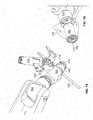
- FIG. 5illustrates an example sterilization system 500 with a sterile adapter 502 and sterile drape 508 attached to a robotic arm 510.
- pegs 504(three pegs as shown in FIG. 5 ) are protruding from the robot interface 506.
- the sterile adapter 502is attached to the robot interface, the pegs 504 protrude through the sterile drape 508.
- the robotic interface 506includes holes and the tool support includes pegs that engage the holes when the tool support is attached to the robotic interface.
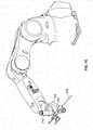
- FIG. 6illustrates an example sterilization system 600 with a sterile adapter 614 and sterile drape 602 attached to a robotic arm 604.
- the system 600includes a sterile drape 602 for covering a surgical robotic arm 604 and preventing contamination of a sterile field.
- the surgical instrument holder 620may be attached to the interface 616 via a tightening screw 618.
- the tightening screw 618may protrude through the sterile drape 602 that is tightly stretched over the opening of the sterile adapter 614.
- the robot interface 616may include one or more positioning elements 622 (e.g., pegs or pins) configured to provide accurate and repeatable positioning of the surgical instrument holder 620 in reference to the robotic arm.
- the surgical instrument holder 620is holding a drill bit guide 624.
- a usermay move the surgical instrument 624 by grasping a handle 606 (e.g., sterile handle).
- An example handle 606is discussed in U.S. Patent Application No. 14/597883 , the contents of which are hereby incorporated by reference in their entirety.
- the handle 606adds functionalities and an interface to existing surgical tools such that the robotic system may be commanded from the sterile field during surgery.
- the handle 606permits a user, such as a surgeon, to physically manipulate the location of the end-effector of a robotic surgical system from a sterile field.
- the handle 606may include an input device that allows the user to limit the movement of the end-effector, such as limiting the movement to translations or rotations only.
- the handle 606may detect the presence of a user's hand. This ensures the end effector is only moved when the user manipulates the handle 606 and reduces the likelihood that the end-effector is moved unintentionally.
- robotic surgical systemmay permit the movement of the end-effector only in circumstances when the presence detector is activated (e.g., a hand of a surgeon is detected as present because the surgeon is holding the sterile handle).
- the handle 606, in certain embodiments,is configured such that it may be used in a sterile environment.
- the design of the handle 606, in certain embodiments,permits rapid mounting of the handle on a surgical tool.
- the handle 606may be designed to avoid tight spaces between various components of the handle 606, thereby simply the sterilization process.
- the sterile drape 602includes a flexible covering with a sterile outer surface.
- the sterile drapemay be partially conformable to a surgical robotic arm.
- the sterile drapemay include an embedded connector 608 configured (e.g., positioned on the flexible covering and sized) to permit electrical contact between the surgical robotic arm 604 (e.g., an actuator of the robotic arm) and a sterile manipulator 606 (e.g., sterile handle) of the robotic arm 604 when the sterile manipulator 606 is separated from the surgical robotic arm 604 by the flexible covering.
- the sterile drape 602is disposable (e.g., a single-use product).
- FIGS. 7A-Cillustrate an example sterilization system applied to a robotic surgical system.
- the robotic surgical systemis for performing surgery, such as spinal surgery.
- the robotic surgical systemmay include a robotic arm 714 with an interface 702 for engaging a sterile adapter 706.
- the sterile adapter 706may be configured to attach to the robotic arm 714 via a robotic interface 706 and tightly stretch the sterile drape 704 to assure repeatable and rigid positioning of the sterile drape 704.
- the sterile drape 704may be configured to protect the robotic arm from contaminating a sterile field.
- the sterile drapeincludes a drape connector configured to electrically couple, through the sterile drape, the manipulator (e.g., handle 606) to an electrical system of the robotic surgical system covered by the sterile drape.
- the manipulator 710e.g., a handle for grasping by a user
- the electrical system of the robotic surgical systemmay be coupled to a robot connector and the robot connector may be configured to electrically connect to the drape connector.
- the robot connectormay electrically couple the drape connector to the robot connector, through the sterile drape 704.
- a surgical instrument holder 714is configured to securely hold the surgical instrument 708.
- the surgical instrument holder 714may be attached to the interface 702 via a tightening screw 716.
- the tightening screw 716may protrude through the sterile drape 704 that is tightly stretched over the opening of the sterile adapter 706.
- the robot interface 702may include one or more positioning elements 712 (e.g., pegs or pins) configured to provide accurate and repeatable positioning of the surgical instrument holder 714 in reference to the robotic arm.
- the one or more positioning elements 712may be round or oblong.
- the surgical instrument holder 714may include one or more studs or holes that engage the one or more positioning elements 712.
- the one or more positioning elements 712may protrude through the sterile drape 704 when the sterile adapter 706 is attached to the interface 702.
- the one or more positioning elements 712extend from the robotic arm 714 and engage one or more surgical instrument holder positioning members.
- the one or more positioning elements 712may be the one or more pegs are configured to extend from the robotic arm and engage one or more holes in the surgical instrument holder 714.
- the robotic surgical systemincludes a manipulator 710 (e.g., a sterile handle) configured to allow robotically-assisted or unassisted positioning and/or movement of the surgical instrument by a user with at least four degrees of freedom to align an axis defined by the surgical instrument at a desired trajectory in relation to a patient situation.
- a manipulator 710e.g., a sterile handle
- the surgical instrumentis a surgical instrument guide configured to hold and/or restrict movement of a second surgical instrument there through.
- the second surgical instrumentmay be a drill bit, tap, screw driver, or awl.
- the second surgical instrumentmay be a drill bit and the surgical instrument guide may be a drill guide.
- the robotic surgical systemincludes a mobile cart configured to transport the robotic surgical system.
- the sterile drapemay be configured to protect the mobile cart from contaminating a sterile field.
- the sterile drapeincludes a first sterile drape to protect the robotic arm 714 and a second sterile drape to protect the mobile cart.
- the sterile drapemay include printed marks configured to assist in proper draping procedure.
- the drapemay be folded in a configuration that makes for easily applying the drape to the robotic system.
- the surgical instrument holderis configured to be attached to the robotic arm using a fastening system.
- the fastening systemmay be a bolt, nut, screw, or one or more electro magnets.
- one or more holding stripesare configured to hold the sterile drape.
- the one or more holding stripesmay secure a portion of the sterile drape to the robotic arm.
- the systemincludes a suppression system configured to remove air from under the sterile drape.
- the suppression systemmay include a ventilator or a suction device that pumps out the air from under the sterile drape.
- the surgical instrument holder 714is made from a non-conductive material (e.g., plastic).
- the holder 714may act as an insulator (prevent electrical conductivity) between the surgical instrument 708 and the robotic arm 714.
- the surgical instrument holder 714is conductive, however, a non-conducive pad is placed between the holder 714 and the interface 702.
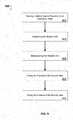
- FIG. 8is a flow chart illustrating an example method 800 of performing a surgical operation with a robotic surgical system.
- the method 800includes attaching a sterile adapter to a robotic arm of a robotic surgical system via a robotic interface (802).
- the a sterile drapemay be coupled to the sterile adapter (e.g., glued or welded) and is configured to protect the robotic arm from contaminating a sterile field.
- the sterile adaptermay be configured to tightly stretch the sterile drape to assure repeatable and rigid positioning of the sterile drape.
- the method 800includes covering a portion of the robotic surgical system with the sterile drape (804) and connecting a drape connector to a handle connector and a robot connector (806).
- the sterile drapemay include the drape connector that is configured to electrically couple the handle connector to the robot connector.
- the method 800includes securing a portion of the sterile drape to the robotic arm via one or more holding stripes (808).
- the method 800includes attaching the surgical tool holder to the robotic arm using a fastening system configured to pass through the sterile adapter and the sterile drape (810).
- the surgical tool holdermay be configured to slide along one or more positioning elements.
- the one or more positioning elements of a robotic arm of the robotic surgical systemmay be configured to cause one or more holes in the sterile drape and also provide accurate and repeatable positioning of the surgical instrument holder in reference to the robotic arm.
- the method 800includes moving a mobile cart transporting the robotic surgical system comprising the robotic arm in proximity to an operating table (812).
- the robotic armhas an end effector that includes a surgical instrument holder holding a surgical instrument attached thereto.
- the method 800includes stabilizing the mobile cart (814) and maneuvering the robotic arm to a desired position to align an axis defined by the surgical instrument at a desired trajectory in relation to a patient situation (816). In some implementations, the method 800 includes, after maneuvering the robotic arm to the desired position, fixing the position of the robotic arm (and, therefore, the position of the surgical instrument) (818).
- FIG. 10is an illustration of an example system 1000 for passing electrical signals through a sterile drape.
- system 1000is achieved using standard (e.g., disposable) cables and connectors. This requires less investment for the developer and user. Moreover, in situations when each cable may only be used for a signal operation, the cost of the disposable components may be significantly reduced.
- the system 100includes a sterile drape 1002 with a sleeve 1004 which allows for passing a plug 1006 of a cable 1008.
- the plug 1006is connected to a sterile handle connector 1010 is used to electrically couple the robotic surgical system to the electrical system of the sterile handle via the cable 1008 and plug 1006.
- the sleeve 1004is sealed using sterile tape 1012.
- the tape 1012may be wrapped around the sleeve 1004 to seal the sleeve 1004.
- the sleeve 1004is part of the sterile drape 1002.
- the sleeve 1004is separate from the drape 1002 and the interface between the sleeve 1004 and the sterile drape 1002 is sealed using sterile adhesive tape 1012 or another sterile adhesive material.
- FIGS. 11A-Dare illustrations of the processor applying a sterile drape that allows passage of electrical signals through the drape.
- FIG. 11Aillustrates a mode selection panel 1102 on a robotic arm 1106 prior to the installation of a sterile drape.
- a sterile handle connector 1108is configured to receive a plug 1114 from a cable connected to the electrical system of the robotic surgical system.
- FIG. 11Bis an illustration of a sterile drape 1110 and sleeve 1112 placed over the connector 1108. After placing the sterile drape 1110 and sleeve 1112 over connector 1108, the plug 1114 is inserted through the hole in the sleeve and plugged into the connector 1108 as shown in FIG> 11C.
- sterile adhesive tapeis wrapped around the sleeve 1112 to seal the sleeve 1112.
- the sleeve 1112is integrated with (e.g., part of) the sterile drape 1110.
- the sleeve 1112is separate from the drape 1110 and the interface between the sleeve 1112 and the sterile drape 1110 is sealed using sterile adhesive tape 1116 or another sterile adhesive material.
- FIGS. 12A-Dare illustrations of an example stiffeners for providing a stiffer sleeve 1206 on a sterile drape 1208.
- the stiffenermay be used to simplify passing the plug 1210 though the flexible sleeve 1206.
- the stiffenermay be rigid (e.g., made from plastic) or semi-rigid member (e.g. made from rubber, adhesive tape, tape reinforcement).
- the sterile drape stiffener 1202may be takes integrated into the drape 1208.
- the stiffenerthe form of a supporting tube 1220 as illustrated in FIG. 12B .
- the supporting tube 1220may be removable.
- the supporting tube 1220may have a longitudinal opening which allows the plug 1210 to be plugged into the connector 1204 through the supporting tube 1220.
- the supporting tube 1220may be inserted before or after applying the drape 1208 to the robot. In some implementations, the supporting tube 1220 may be removably attached to the drape. In some implementations, after inserting the plug 1210 into the connector 1204, the supporting tube 1220 may be removed and sterile adhesive tape is applied to the sleeve 1206 (e.g., as described above).
- the connector adapter 1230is integrated into the drape 1208 as shown in FIG. 12C .
- the connector adapter 1230may fit around the connector 1204 and allow for simple access to the connector 1204 by the plug 1210.
- Sterile adhesive tapemay be applied to the sleeve 1206 after the plug 1210 is inserted into the connector 1204 (e.g., as described above).
- a drape 1208 with a folded section 1242is placed around the connector 1240 as shown in FIG. 12D .
- the folded section 1242 of the drape 1208is unfolded and sterile adhesive tape is applied (e.g., as described above).
- FIG. 13is an illustration of an example system for passing electrical signals through a sterile drape.
- FIG. 13illustrates a sterile adapter 1306 (e.g., as described above) and a connector opening 1308.
- a cable and plugare attached to the drape 1302 before draping the robot. For example, a scrub nurse may do this on a sterile table.
- the cablemay be passed through the sleeve 1304.
- the drape 1302 and/or sleeve 1304is/are folded to facilitate passing the cable through the sleeve 1304. After passing the cable through the sleeve 1304, it may be sealed using sterile adhesive tape (e.g., as described above). After sealing the plug and sleeve 1304, the drape 1302 may be applied to the robot and the plug may be connected to the connector by manipulating it from the sterile side of the drape 1302.
Landscapes
- Health & Medical Sciences (AREA)
- Surgery (AREA)
- Life Sciences & Earth Sciences (AREA)
- Engineering & Computer Science (AREA)
- Biomedical Technology (AREA)
- Heart & Thoracic Surgery (AREA)
- Medical Informatics (AREA)
- Molecular Biology (AREA)
- Animal Behavior & Ethology (AREA)
- General Health & Medical Sciences (AREA)
- Public Health (AREA)
- Veterinary Medicine (AREA)
- Manipulator (AREA)
Description
- Robotic-assisted surgical systems have been developed to improve surgical precision and enable the implementation of new surgical procedures. For example, robotic systems have been developed to sense a surgeon's hand movements and translate them to scaled-down micro-movements and filter out unintentional tremors for precise microsurgical techniques in organ transplants, reconstructions, and minimally invasive surgeries. Other robotic systems are directed to telemanipulation of surgical tools such that the surgeon does not have to be present in the operating room, thereby facilitating remote surgery. Feedback-controlled robotic systems have also been developed to provide smoother manipulation of a surgical tool during a procedure than could be achieved by an unaided surgeon.
- However, widespread acceptance of robotic systems by surgeons and hospitals is limited for a variety of reasons. Current systems are expensive to own and maintain. They often require extensive preoperative surgical planning prior to use, and they extend the required preparation time in the operating room. They are physically intrusive, possibly obscuring portions of a surgeons field of view and blocking certain areas around the operating table, such that a surgeon and/or surgical assistants are relegated to one side of the operating table. Current systems may also be non-intuitive or otherwise cumbersome to use, particularly for surgeons who have developed a special skill or "feel" for performing certain maneuvers during surgery and who find that such skill cannot be implemented using the robotic system. Finally, robotic surgical systems may be vulnerable to
- malfunction or operator error, despite safety interlocks and power backups.
WO 2013/160239 A1 discloses a sterile drape for covering a surgical robot arm. US 4799779 A discloses a surgical drape for covering a microscope having side sleeves.- Spinal surgeries often require precision drilling and placement of screws or other implements in relation to the spine, and there may be constrained access to the vertebrae during surgery that makes such maneuvers difficult. Catastrophic damage or death may result from improper drilling or maneuvering of the body during spinal surgery, due to the proximity of the spinal cord and arteries. Common spinal surgical procedures include a discectomy for removal of all or part of a disk, a foraminotomy for widening of the opening where nerve roots leave the spinal column, a laminectomy for removal of the lamina or bone spurs in the back, and spinal fusion for fusing of two vertebrae or vertebral segments together to eliminate pain caused by movement of the vertebrae.
- Spinal surgeries that involve screw placement require preparation of holes in bone (e.g., vertebral segments) prior to placement of the screws. Where such procedures are performed manually, in some implementations, a surgeon judges a drill trajectory for subsequent screw placement on the basis of pre-operative CT scans. Other manual methods which do not involve usage of the pre-operative CT scans, such as fluoroscopy, 3D fluoroscopy or natural landmark-based, may be used to determine the trajectory for preparing holes in bone prior to placement of the screws. In some implementations, the surgeon holds the drill in his hand while drilling, and fluoroscopic images are obtained to verify if the trajectory is correct. Some surgical techniques involve usage of different tools, such as a pedicle finder or K-wires. Such procedures rely strongly on the expertise of the surgeon, and there is significant variation in success rate among different surgeons. Screw misplacement is a common problem in such surgical procedures.
- Image-guided spinal surgeries involve optical tracking to aid in screw placement. However, such procedures are currently performed manually, and surgical tools can be inaccurately positioned despite virtual tracking. A surgeon is required to coordinate his real-world, manual manipulation of surgical tools using images displayed on a two dimensional screen. Such procedures can be non-intuitive and require training, since the surgeon's eye must constantly scan both the surgical site and the screen to confirm alignment. Furthermore, procedural error can result in registration inaccuracy of the image-guiding system, rendering it useless, or even misleading.
- Certain force feedback systems are used by surgeons in certain procedures; however such systems have a large footprint and take up valuable, limited space in the operating room. These systems also require the use of surgical tools that are specially adapted for use with the force feedback system, and the training required by surgeons to operate such systems can be significant. Moreover, surgeons may not be able to use expertise they have developed in performing spinal surgeries when adapting to use of the current force feedback systems. Such systems, while precise, may require more surgical time and more operating room preparation time to ready placement of the equipment for surgery. Thus, there is a need for systems and apparatus that provide enhanced precision in performing surgeries such as spinal surgeries.
- Described herein are a sterile drape and adapter for use with a robotic surgical system, for example, during spinal surgery. The invention is defined by claim 1. Further embodiments of the invention are defined by the dependent claims.
- In certain embodiments, the sterile drape and adapter cover a robotic surgical arm and prevent contamination of a sterile field. The sterile drape may attached to the robotic arm via a sterile adapter that ensures the drape is tightly stretched over the tool holder and robot interface to provide a structure that provides for repeatable and rigid positioning of the sterile drape. Tightly stretching the drape over the sterile adapter and tightening the tool holder to the robotic arm using, for example, a tightening screw, reduces the likelihood of folds in the drape between the told holder and robot interface. Thus, errors caused by inaccurate positioning of the tool holder relative to the robot interface are minimized. Moreover, tightly stretching the drape over sterile adapter ensures that the sterile adapter is easy to perforate when the sterile tool holder is installed. As the tightening screw securely is tightened to the appropriate torque specification, a hermetically sealed zone is formed by the tool holder, sterile adapter, and robotic arm. The hermetically sealed zone contains the perforated sections of the sterile drape, thus ensuring the robotic system may be used in a sterile environment even after the tool support is attached to the robotic arm.
- In certain embodiments, the disclosed technology includes a sterile drape for covering a surgical robotic arm and preventing contamination of a sterile field. In some implementations, the sterile drape includes a flexible covering with a sterile outer surface. The covering may be at least partially conformable to a surgical robotic arm. The sterile drape may include an embedded connector configured (e.g., positioned on the flexible covering and sized) to permit electrical contact between the surgical robotic arm (e.g., an actuator of the robotic arm) and a sterile manipulator (e.g., sterile handle) of the robotic arm when the sterile manipulator is separated from the surgical robotic arm by the flexible covering. In some implementations, the sterile drape is disposable (e.g., a single-use product).
- In certain embodiments, the disclosed technology includes a rigid or semi-rigid sterile adapter (e.g., made from a hard plastic, a polymer, or a composite material) for securing a sterile drape over a surgical robotic arm to prevent contamination of a sterile field. In some implementations, the sterile adapter includes a rigid or semi-rigid collar (e.g., ring) configured to mount (e.g., snap-mount) onto an interface of the surgical robotic arm. The sterile adapter may include a rigid or semi-rigid body extending from the collar and shaped to conform to a portion of the surgical robotic arm to tightly secure a flexible drape in place (e.g., with no folds) over the portion of the surgical robotic arm when the drape is attached to the adapter. In some implementations, the sterile adapter is disposable (e.g. a single-use product).
- In certain embodiments, the disclosed technology includes a sterile drape that is attached (e.g., glued or welded) to a sterile adapter. In some implementations, the sterile adapter that ensures the drape is tightly stretched over the tool holder and robot interface to protect the robotic arm and mobile cart from contaminating the sterile field, and provides a structure that provides for repeatable and rigid positioning of the sterile drape.
- The disclosed technology, in certain embodiments, includes a sterile drape for covering a surgical robotic arm and preventing contamination of a sterile field. The sterile drape includes, in certain embodiments, a flexible covering with a sterile outer surface and a sterile drape sleeve configured to receive an electrical plug therethrough, said covering being at least partially conformable to a surgical robotic arm. In certain embodiments, the sterile drape sleeve is configured to be sealed around a portion of the electrical plug using a sterile adhesive tape. The sterile drape sleeve, in certain embodiments, is configured to surround at least a portion of a connector of the surgical robotic arm and extend outwardly from the connector.
- In certain embodiments, the connector is configured to permit electrical contact between the surgical robotic arm (e.g., an actuator of the robotic arm) and a sterile manipulator (e.g., sterile handle) of the robotic arm when the sterile manipulator is separated from the surgical robotic arm by the flexible covering.
- In certain embodiments, the sterile drape is configured to be attached to the sterile drape before draping the robotic surgical arm. In certain embodiments, the connector is configured to receive the electrical plug after the electrical plug is passed through the sterile drape sleeve. In certain embodiments, the connector is configured to receive the electrical plug after (i) the electrical plug is passed through the sterile drape sleeve and (ii) the sterile drape sleeve is sealed around a portion of the electrical plug using a sterile adhesive tape.
- In certain embodiments, the sterile drape is configured to be attached to the sterile drape after draping the robotic surgical arm. In certain embodiments, the sterile drape comprises a drape stiffener configured to assist in passing the electrical plug through the sterile drape sleeve. In certain embodiments, the drape stiffener is made of a semi-rigid material (e.g., rubber, adhesive tape, tape reinforcement). In certain embodiments, the drape stiffener is made of a rigid material (e.g., plastic). In certain embodiments, the drape stiffener is integrated in the sterile drape. In certain embodiments, the drape stiffener is removable. In certain embodiments, the drape stiffener is configured to be inserted before the sterile drape is applied to the robot surgical arm. In certain embodiments, the drape stiffener is configured to be inserted after the sterile drape is applied to the robot surgical arm. In certain embodiments, the drape stiffener is configured to be removed after the sterile drape is applied to the robot surgical arm. In certain embodiments, the drape stiffener is configured to be removed after (i) the sterile drape is applied to the robot surgical arm and (ii) the sterile drape sleeve is sealed around a portion of the electrical plug using a sterile adhesive tape.
- In certain embodiments, the disclosed technology includes a sterile drape for covering a surgical robotic arm and preventing contamination of a sterile field. In certain embodiments, the sterile drape includes a flexible covering with a sterile outer surface, said covering being at least partially conformable to a surgical robotic arm. In certain embodiments, the flexible covering includes a drape opening that is configured to be contained within a sealed chamber formed by the surgical robotic arm, a sterile adapter, and a surgical tool holder such that a fastening system may pass through the chamber and the drape opening when the surgical instrument holder is coupled to the surgical robotic arm.
- In certain embodiments, the fastening system comprises one or more positioning elements that extend from the surgical robotic arm and engage one or more surgical instrument holder positioning members. In certain embodiments, the one or more positioning elements are one or more pegs. In certain embodiments, the one or more pegs are configured to extend from the robotic arm and engage one or more holes in the surgical instrument holder. In certain embodiments, the fastening system comprises a fastening member configured to securely attach the surgical instrument holder to the surgical robotic arm. In certain embodiments, the fastening member is a member selected from the group consisting of a bolt, nut, screw, and one or more electro magnets.
- In certain embodiments, the disclosed technology includes a sterile drape for covering a surgical robotic arm and preventing contamination of a sterile field. In certain embodiments, the sterile drape includes a flexible covering with a sterile outer surface, said covering being at least partially conformable to a surgical robotic arm; and an embedded connector configured (e.g., positioned on the flexible covering and sized) to permit electrical contact between the surgical robotic arm (e.g., an actuator of the robotic arm) and a sterile manipulator (e.g., sterile handle) of the robotic arm when the sterile manipulator is separated from the surgical robotic arm by the flexible covering.
- In certain embodiments, the disclosed technology includes a rigid or semi-rigid sterile adapter (e.g., made from a hard plastic, a polymer, or a composite material) for securing a sterile drape over a surgical robotic arm to prevent contamination of a sterile field. In certain embodiments, the sterile adapter includes a rigid or semi-rigid collar (e.g., ring) configured to mount (e.g., snap-mount) onto an interface of the surgical robotic arm; and a rigid or semi-rigid body extending from the collar and shaped to conform to a portion of the surgical robotic arm to tightly secure a flexible drape in place (e.g., with no folds) over the portion of the surgical robotic arm when the drape is attached to the adapter.
- In certain embodiments, the sterile drape is disposable (e.g., a single-use product). In certain embodiments, the sterile adapter is disposable (e.g. a single-use product).
- In certain embodiments, the disclosed technology includes an apparatus that includes a sterile drape and a sterile adapter. In some implementations, the apparatus is disposable (e.g., a single-use product).
- In certain embodiments, the disclosed technology includes a robotic surgical system for performing surgery. In some implementations, the system includes a robotic arm with an end effector, a surgical instrument holder configured to securely hold the surgical instrument, and one or more positioning elements configured to provide accurate and repeatable positioning of the surgical instrument holder in reference to the robotic arm; a manipulator configured to allow robotically-assisted or unassisted positioning and/or movement of the surgical instrument by a user with at least four degrees of freedom to align an axis defined by the surgical instrument at a desired trajectory in relation to a patient situation; a sterile drape configured to protect the robotic arm from contaminating a sterile field.
- In certain embodiments, the sterile drape includes a drape connector configured to electrically couple, through the sterile drape, the manipulator to an electrical system of the robotic surgical system covered by the sterile drape, and the one or more positioning elements pass through the sterile drape. In certain embodiments, a sterile adapter is configured to attach to the robotic arm via a robotic interface and tightly stretch the sterile drape to assure repeatable and rigid positioning of the sterile drape. In certain embodiments, the surgical instrument holder is attached to the robotic arm using a fastening system configured to pass through the sterile adapter and the sterile drape.
- In certain embodiments, the surgical instrument comprises a surgical instrument guide configured to hold and/or restrict movement of a second surgical instrument there through. In certain embodiments, the second surgical instrument is a member selected from the group consisting of: a drill bit, tap, screw driver, and awl. In certain embodiments, the second surgical instrument is a drill bit and the surgical instrument guide is a drill guide. In certain embodiments, the robotic surgical system is for use in spinal surgery.
- In certain embodiments, the one or more positioning elements extend from the robotic arm and engage one or more surgical instrument holder positioning members. In certain embodiments, the one or more positioning elements are one or more pegs. In certain embodiments, the one or more pegs are configured to extend from the robotic arm and engage one or more holes in the surgical instrument holder. In certain embodiments, the one or more positioning elements are configured to pass through the sterile drape.
- In certain embodiments, the system includes a mobile cart configured to transport the robotic surgical system, wherein the sterile drape is configured to protect the mobile cart from contaminating a sterile field. In certain embodiments, the sterile drape comprises a first sterile drape to protect the robotic arm and a second sterile drape to protect the mobile cart.
In certain embodiments, the sterile drape comprises printed marks configured to assist in proper draping procedure. In certain embodiments, the system includes one or more holding stripes configured to hold the sterile drape (e.g., securely in place). In certain embodiments, the one or more holding stripes secure a portion of the sterile drape to the robotic arm. - In certain embodiments, the system includes a suppression system configured to remove air from under the sterile drape. In certain embodiments, the suppression system includes at least one member selected from the group consisting of a ventilator and a suction device that pumps out the air from under the sterile drape. In certain embodiments, the sterile handle is coupled to a handle connector via a cable and the handle connector is configured to electrically connect to the drape connector.
- In certain embodiments, the electrical system of the robotic surgical system is coupled to a robot connector and the robot connector is configured to electrically connect to the drape connector. In certain embodiments, the robot connector electrically couples the drape connector to the robot connector.
- In certain embodiments, the sterile adapter comprises one or more tabs configured to attach to the robotic arm. In certain embodiments, the one or more tabs click onto an interface on the robotic arm. In certain embodiments, the one or more tabs comprise four tabs.
- In certain embodiments, the sterile drape is glued or welded to the sterile adapter.
- In certain embodiments, the sterile drape passes between the surgical instrument tool holder and the robotic interface. In certain embodiments, the sterile drape is tightly stretched between the surgical instrument tool holder and the robotic interface. In certain embodiments, the surgical instrument holder is a non-conductive material.
- In certain embodiments, the disclosed technology includes an exemplary not claimed method of performing surgery with a robotic surgical system. In certain embodiments, the method includes attaching a sterile adapter to a robotic arm of a robotic surgical system via a robotic interface, wherein: a sterile drape is coupled to the sterile adapter and is configured to protect the robotic arm from contaminating a sterile field, and the sterile adapter is configured to tightly stretch the sterile drape to assure repeatable and rigid positioning of the sterile drape; covering a portion of the robotic surgical system with the sterile drape; connecting a drape connector to a handle connector and a robot connector, wherein the sterile drape comprises the drape connector and the drape connector is configured to electrically couple the handle connector to the robot connector; securing a portion of the sterile drape to the robotic arm via one or more holding stripes; attaching the surgical tool holder to the robotic arm using a fastening system configured to pass through the sterile adapter and the sterile drape, wherein: the surgical tool holder is configured to slide along one or more positioning elements, the one or more positioning elements of a robotic arm of the robotic surgical system are configured to cause one or more holes in the sterile drape, and the one or more position elements are configured to provide accurate and repeatable positioning of the surgical instrument holder in reference to the robotic arm; moving a mobile cart transporting the robotic surgical system comprising the robotic arm in proximity to an operating table, wherein the robotic arm has an end effector comprising a surgical instrument holder holding a surgical instrument attached thereto; stabilizing the mobile cart; maneuvering the robotic arm to a desired position to align an axis defined by the surgical instrument at a desired trajectory in relation to a patient situation; and fixing the position of the robotic arm (and, therefore, the position of the surgical instrument).
- In certain embodiments, the exemplary method includes maneuvering the second surgical instrument through the surgical instrument guide. In certain embodiments, the method includes maneuvering a drill bit through a drill bit guide. In certain embodiments, the sterile drape is configured to cover the robotic arm and mobile cart and protect the robotic arm and mobile cart from contaminating a sterile field. In certain embodiments, the fastening system goes through the sterile drape. In certain embodiments, the one or more holding stripes wrap around the robotic arm. In certain embodiments, a suppression system configured to remove air from under the sterile drape. In certain embodiments, the suppression system comprises at least one member selected from the group consisting of a ventilator and a suction device that pumps out the air from under the sterile drape. In certain embodiments, stabilizing the mobile cart includes extracting one or more rigid legs on the mobile cart such that the mobile cart rests on the one or more rigid legs of the mobile cart. In certain embodiments, stabilizing the mobile cart comprises retracting one or more wheels on the mobile cart such that the mobile cart rests on one or more rigid legs of the mobile cart.
- In certain embodiments, the method includes, prior to maneuvering the robotic arm to a desired position, obtaining or accessing a CT scan, 3D CT scan, fluoroscopy, 3D fluoroscopy, or natural landmark-based image of the patient situation. In certain embodiments, the desired trajectory is a desired path of the surgical tool.
- The foregoing and other objects, aspects, features, and advantages of the present disclosure will become more apparent and better understood by referring to the following description taken in conjunction with the accompanying drawings, in which:
FIG. 1 is an illustration of an example robotic surgical system;FIG. 2 is an illustration of an example sterile adapter for use with a robotic surgical system;FIG. 3 is an illustration of an example sterile drape coupled, via glue or welding, to a sterile adapter;FIGS. 4A-B are illustrations of an example sterile adapter applied to a robotic surgical system;FIG. 5 is an illustration of an example sterilization system with a sterile adapter and sterile drape attached to a robotic arm;FIG. 6 is an illustration of an example a sterilization system with a sterile adapter and sterile drape attached to a robotic arm;FIGS. 7A-C are illustrations of an example sterilization system applied to a robotic surgical system;FIG. 8 is a flowchart of an example method of performing surgery with a robotic surgical system;FIG. 9 is a flowchart of an example of a method for performing a minimally invasive surgery using a robotic surgical system as a drill guide;FIG. 10 is an illustrations of an example system for passing electrical signals through a sterile drape;FIG. 11A-D are illustrations of the processor applying a sterile drape that allows passage of electrical signals through the drape;FIGS. 12A-D are illustrations of an example stiffeners for improving the ability to pass an electrical plug through a sleeve of a sterile drape;FIG. 13 is an illustrations of an example system for passing electrical signals through a sterile drape; andFIG. 14 is an illustration of an example sterile drape for use with a robotic surgical system.- The features and advantages of the present disclosure will become more apparent from the detailed description set forth below when taken in conjunction with the drawings, in which like reference characters identify corresponding elements throughout. In the drawings, like reference numbers generally indicate identical, functionally similar, and/or structurally similar elements.
FIG. 1 illustrates an example roboticsurgical system 100. In some implementations, one or more surgeons, surgical assistants, surgical technologists and/or other technicians, perform an operation on a patient using a robotic-assistedsurgical system 100. In the operating room the surgeon may be guided by therobotic system 100 to accurately execute an operation. The roboticsurgical system 100 may be transported in and out of an operating room using amobile cart 104. Accordingly, the roboticsurgical system 100, including themobile cart 104, must be sterilized when used in the operating room. The system may be sterilized by applying a sterile drape 102 to a portion of thesystem 100, including at least part of therobotic arm 106 and themobile cart 104. The sterile drape 102 may consist of a single drape or several pieces, such assterile cover 102a for covering therobotic arm 106 andsterile drape 102b for covering themobile cart 104.- In some implementations, the sterile drape 102 is attached (e.g., glued or welded) to a
sterile adapter 108. Thesterile adapter 108 may be attached (e.g., clipped) to an interface on therobotic arm 106. Thesterile adapter 108 ensures the drape 102 is tightly stretched over the interface between thetool holder 110 and robot interface to protect therobotic arm 106 andmobile cart 104 from contaminating the sterile field, and provides a structure that provides for repeatable and rigid positioning of the sterile drape 102. Tightly stretching the drape 102 between the robot interface andtool holder 110 and tightening the tool holder to the robotic arm using, for example, a tightening screw, reduces the likelihood of folds in the drape 102 between the toldholder 110 and robot interface. Thus, errors between the robot model and the actual situation because of the position of thetool holder 110 relative to the robot interface are minimized. If folds are present, the positioning of thetool holder 110 relative to the robot interface will be different than anticipated and the roboticsurgical system 100 may have difficulty positioning tools held by thetool holder 110 appropriately. - A
sterile tool holder 110 may be connected to therobotic arm 106 through the sterile drape 102. Thetool holder 110 may hold sterile surgical instruments (e.g., tool guide 112) and may be coupled to a navigation marker 114. Thus, the disclosed technology enables a roboticsurgical system 100 to be used in a sterile operating room without having to sterilize each individual component of the system. Only the components outside of the sterile drape 102 (e.g., the optical marker 114, surgical instruments (e.g., 112), andtool holder 110 must be sterilized individually. - A
band 116 may be provided around theforce sensor 120 mounted on the robotic arm. Band 116 may provideforce sensor 120 protection. For example, in some implementations, the force sensor measures forces applied to all parts attached to it (e.g., sterile adapter, tool guide, optical marker, etc.). The sterile drape is attached to the sterile adapter and when, for example, the robotic arm moves or somebody touches the drape, the drape can tear on the force sensor and/or impact the measurements by the force sensor. By adding force sensor protection (e.g., band 116), this problem is mitigated. The drape 102 may also be secured around therobotic arm 106 using holdingstripes 118. In some implementations, the a suppression system, such as a pump, ventilator, or other suction device may be used to remove air from inside the device. In some implementations, the holdingstrips 118 are used in combination with a suppression system. FIG. 2 is an illustration of an examplesterile adapter 200 for use with a robotic surgical system. Thesterile adapter 200 may be a disposable (e.g. a single-use product). For example, a newsterile adapter 200 may be used for every surgical procedure. In some implementations, thesterile adapter 200 is a rigid or semi-rigid device. It may be made from a hard plastic, polymer, or a composite material. In some implementations, thesterile adapter 200 secures a drape over a surgical robotic arm to prevent contamination of a sterile field.- The
sterile adapter 200 may include a rigid or semi-rigid collar 202 (e.g., ring or a hollow cylindrical structure) configured to mount (e.g., snap-mount) onto an interface of the surgical robotic arm. Thesterile adapter 200 may include a rigid or semi-rigid body 204 extending from the collar and shaped to conform to a portion of the surgical robotic arm to tightly secure a flexible drape in place (e.g., with no folds) over the portion of the surgical robotic arm when the drape is attached to theadapter 200. - In some implementations, the body 204 is one or
more tabs 204a-d (e.g., 3, 4, 5, 6, 7, or 8 tabs) that engage an interface on the robot. The tabs may "click" into the interface to provide easy and secure mounting of the sterile adapter, and hence sterile drape, on the robot. The sterile drape may be glued or welded to the sterile adapter 200 (e.g., during manufacturing). Theadapter 200 ensures that the drape is tightly stretched over the tool holder and robot interface to provide repeatable and rigid positioning of the tool holder relative to the robotic arm.FIG. 3 is an illustration of ansterile drape 304 coupled, via glue or welding, to asterile adapter 302. In some implementations, thesterile drape 304 is glued or welded to thesterile adapter 302. After the welding/gluing dries the part of the drape inside thesterile adapter 302 is stretched. This portion of the drape (i.e., the stretched portion inside of thesterile adapter 302 is the only part of the drape that is located between the tool holder and the robotic arm. As shown inFIG. 3 , thesterile drape 304 is tightly stretched over the opening of thesterile adapter 302. When thesterile adapter 302 is attached to the robotic arm (e.g., clicked into the interface on the robotic arm), the end of the robotic arm will be covered by thesterile drape 304 that is stretched over the opening of thesterile adapter 302. As described below, in some implementations, positioning elements and a tightening screw will protrude through the opening of the sterile adapter and piece the sterile drape when the tool support is applied to the robotic arm. FIG. 4A-B illustrate an examplesterile adapter 400 applied to a roboticsurgical system 450. Tabs/clips 402 engage grooves 404 on theinterface 406 of the robot arm. In some implementations, the tabs/clips 402 include a single tab/clip. The tabs/clips may "click" to engage the groove(s) 402 on therobot interface 406. After thesterile adapter 400 is attached to therobot interface 406, thetool holder 410 may be attached to the robot. Thetool holder 410 may include one or more positioning members 412 (e.g., pins or pegs) that engage one ormore holes 414 in therobot interface 406 to provide accurate/repeatable positioning of the tool holder in reference to the robot interface. The one ormore positioning members 412 may pierce thesterile drape 416 to engage the hole(s) 414. In some implementations, as shown inFIG. 14 , thesterile drape 1404 includes adrape opening 1406 that is large enough to allow passage of the positioning pins without puncturing the drape. Thesterile adapter 1402 stretches the drape to avoid folds as described above. Thedrape opening 1406 is configured to be located inside the sterile adapter 1402 (i.e., the sterile drape does is not on the inside of the sterile adapter). Adust cover 1408 may be placed over thedrape opening 1406 and attached to thedrape 1404. Thedust cover 1408 may be configured to attach to thedrape 1404 using an adhesive material. Thedust cover 1408 may be removed after thedrape 1404 is installed, for example, on the robotic surgical arm, thus reducing contamination of the sterile field. After thesterile drape 1404 is installed, thedust cover 1408 may be removed and the tool holder may be installed.- In some implementations, the position member(s) 412 may be uniquely shaped to ensure that the
tool holder 410 is always appropriately positioned/ oriented on therobot interface 406. In some implementations, the positioning member(s) is/are located on therobot interface 406 and the hole(s) 414 is/are located on the tool holder 410 (i.e., opposite of what is shown inFIG. 4B ). - The
tool holder 410 may be securely attached to the robot using a tighteningscrew 408. The tighteningscrew 408 may be tightened using a torque wrench or other torque-limited tool. In some implementations, the wrench is disposable and/or destroyed after achieving a certain torque. When the tightening screw is tightened, it pieces thesterile drape 416 and engages threads on therobot interface 406. As discussed above, thesterile drape 416 is tightly stretched over thesterile adapter 400, thus when the tighteningscrew 408 is tightened to the appropriate torque setting, only a single layer of thesterile adapter 400 material is between thetool holder 410 and therobot interface 406. Moreover, tightly stretching thedrape 416 over sterile adapter ensures that thesterile adapter 408 is easy to perforate (e.g., by the position member(s) and the tightening screw) when thesterile tool holder 410 is installed. In some implementations, the a bolt or nut is used to securely attached thetool holder 410 to the robot. In some implementations, electromagnet(s) is/are used to securely attached thetool holder 410 to the robot. In some implementations, the tighteningscrew 408 and the positioning member(s) 414 protrude through thesterile drape 416. In some implementations, these perforations (e.g., holes in the sterile drape 416) are in the inner space formed by therobot interface 406, thesterile adapter 400, and thetool holder 410. In some implementations, this inner space is hermetically sealed by these three components when the tighteningscrew 408 is torqued to the appropriate specification. FIG. 5 illustrates anexample sterilization system 500 with asterile adapter 502 andsterile drape 508 attached to a robotic arm 510. In this example, pegs 504(three pegs as shown inFIG. 5 ) are protruding from therobot interface 506. When thesterile adapter 502 is attached to the robot interface, thepegs 504 protrude through thesterile drape 508. When the tool support is attached, holes in the tool support engage the pegs and ensure the tool support is properly installed and oriented relative to the robotic arm. In some other implementations, therobotic interface 506 includes holes and the tool support includes pegs that engage the holes when the tool support is attached to the robotic interface.FIG. 6 illustrates anexample sterilization system 600 with asterile adapter 614 andsterile drape 602 attached to arobotic arm 604. In some implementations, thesystem 600 includes asterile drape 602 for covering a surgicalrobotic arm 604 and preventing contamination of a sterile field.- The
surgical instrument holder 620 may be attached to theinterface 616 via a tighteningscrew 618. The tighteningscrew 618 may protrude through thesterile drape 602 that is tightly stretched over the opening of thesterile adapter 614. Therobot interface 616 may include one or more positioning elements 622 (e.g., pegs or pins) configured to provide accurate and repeatable positioning of thesurgical instrument holder 620 in reference to the robotic arm. In the example shown inFIG. 6 , thesurgical instrument holder 620 is holding adrill bit guide 624. A user may move thesurgical instrument 624 by grasping a handle 606 (e.g., sterile handle). An example handle 606 is discussed in U.S. Patent Application No.14/597883 - In certain embodiments, the
handle 606 adds functionalities and an interface to existing surgical tools such that the robotic system may be commanded from the sterile field during surgery. Thehandle 606 permits a user, such as a surgeon, to physically manipulate the location of the end-effector of a robotic surgical system from a sterile field. Thehandle 606 may include an input device that allows the user to limit the movement of the end-effector, such as limiting the movement to translations or rotations only. Thehandle 606 may detect the presence of a user's hand. This ensures the end effector is only moved when the user manipulates thehandle 606 and reduces the likelihood that the end-effector is moved unintentionally. For example, robotic surgical system may permit the movement of the end-effector only in circumstances when the presence detector is activated (e.g., a hand of a surgeon is detected as present because the surgeon is holding the sterile handle). Thehandle 606, in certain embodiments, is configured such that it may be used in a sterile environment. The design of thehandle 606, in certain embodiments, permits rapid mounting of the handle on a surgical tool. Thehandle 606 may be designed to avoid tight spaces between various components of thehandle 606, thereby simply the sterilization process. - In some implementations, the
sterile drape 602 includes a flexible covering with a sterile outer surface. The sterile drape may be partially conformable to a surgical robotic arm. The sterile drape may include an embeddedconnector 608 configured (e.g., positioned on the flexible covering and sized) to permit electrical contact between the surgical robotic arm 604 (e.g., an actuator of the robotic arm) and a sterile manipulator 606 (e.g., sterile handle) of therobotic arm 604 when thesterile manipulator 606 is separated from the surgicalrobotic arm 604 by the flexible covering. In some implementations, thesterile drape 602 is disposable (e.g., a single-use product). FIGS. 7A-C illustrate an example sterilization system applied to a robotic surgical system. In some implementations, the robotic surgical system is for performing surgery, such as spinal surgery. The robotic surgical system may include arobotic arm 714 with aninterface 702 for engaging asterile adapter 706. Thesterile adapter 706 may be configured to attach to therobotic arm 714 via arobotic interface 706 and tightly stretch thesterile drape 704 to assure repeatable and rigid positioning of thesterile drape 704. Thesterile drape 704 may be configured to protect the robotic arm from contaminating a sterile field.- In some implementations, the sterile drape includes a drape connector configured to electrically couple, through the sterile drape, the manipulator (e.g., handle 606) to an electrical system of the robotic surgical system covered by the sterile drape. The manipulator 710 (e.g., a handle for grasping by a user) may be coupled to a handle connector via a cable and the handle connector is configured to electrically connect to the drape connector. The electrical system of the robotic surgical system may be coupled to a robot connector and the robot connector may be configured to electrically connect to the drape connector. Thus, the robot connector may electrically couple the drape connector to the robot connector, through the
sterile drape 704. - In some implementations, a
surgical instrument holder 714 is configured to securely hold thesurgical instrument 708. Thesurgical instrument holder 714 may be attached to theinterface 702 via a tighteningscrew 716. The tighteningscrew 716 may protrude through thesterile drape 704 that is tightly stretched over the opening of thesterile adapter 706. Therobot interface 702 may include one or more positioning elements 712 (e.g., pegs or pins) configured to provide accurate and repeatable positioning of thesurgical instrument holder 714 in reference to the robotic arm. The one ormore positioning elements 712 may be round or oblong. Thesurgical instrument holder 714 may include one or more studs or holes that engage the one ormore positioning elements 712. The one ormore positioning elements 712 may protrude through thesterile drape 704 when thesterile adapter 706 is attached to theinterface 702. In some implementations, the one ormore positioning elements 712 extend from therobotic arm 714 and engage one or more surgical instrument holder positioning members. For example, the one ormore positioning elements 712 may be the one or more pegs are configured to extend from the robotic arm and engage one or more holes in thesurgical instrument holder 714. - In some implementations, the robotic surgical system includes a manipulator 710 (e.g., a sterile handle) configured to allow robotically-assisted or unassisted positioning and/or movement of the surgical instrument by a user with at least four degrees of freedom to align an axis defined by the surgical instrument at a desired trajectory in relation to a patient situation.
- In some implementations, the surgical instrument is a surgical instrument guide configured to hold and/or restrict movement of a second surgical instrument there through. The second surgical instrument may be a drill bit, tap, screw driver, or awl. For example, in the case of spinal surgery, the second surgical instrument may be a drill bit and the surgical instrument guide may be a drill guide.
- In some implementations, the robotic surgical system includes a mobile cart configured to transport the robotic surgical system. The sterile drape may be configured to protect the mobile cart from contaminating a sterile field. In some implementations, the sterile drape includes a first sterile drape to protect the
robotic arm 714 and a second sterile drape to protect the mobile cart. In some implementations, the sterile drape may include printed marks configured to assist in proper draping procedure. In some implementations, the drape may be folded in a configuration that makes for easily applying the drape to the robotic system. - In some implementations, the surgical instrument holder is configured to be attached to the robotic arm using a fastening system. The fastening system may be a bolt, nut, screw, or one or more electro magnets.
- In some implementations, one or more holding stripes are configured to hold the sterile drape. The one or more holding stripes may secure a portion of the sterile drape to the robotic arm. In some implementations, the system includes a suppression system configured to remove air from under the sterile drape. The suppression system may include a ventilator or a suction device that pumps out the air from under the sterile drape.
- In some implementations, the
surgical instrument holder 714 is made from a non-conductive material (e.g., plastic). Theholder 714 may act as an insulator (prevent electrical conductivity) between thesurgical instrument 708 and therobotic arm 714. In some implementations, thesurgical instrument holder 714 is conductive, however, a non-conducive pad is placed between theholder 714 and theinterface 702. FIG. 8 is a flow chart illustrating anexample method 800 of performing a surgical operation with a robotic surgical system. In some implementations, themethod 800 includes attaching a sterile adapter to a robotic arm of a robotic surgical system via a robotic interface (802). The a sterile drape may be coupled to the sterile adapter (e.g., glued or welded) and is configured to protect the robotic arm from contaminating a sterile field. The sterile adapter may be configured to tightly stretch the sterile drape to assure repeatable and rigid positioning of the sterile drape.- In some implementations, the
method 800 includes covering a portion of the robotic surgical system with the sterile drape (804) and connecting a drape connector to a handle connector and a robot connector (806). The sterile drape may include the drape connector that is configured to electrically couple the handle connector to the robot connector. - In some implementations, the
method 800 includes securing a portion of the sterile drape to the robotic arm via one or more holding stripes (808). In some implementations, themethod 800 includes attaching the surgical tool holder to the robotic arm using a fastening system configured to pass through the sterile adapter and the sterile drape (810). The surgical tool holder may be configured to slide along one or more positioning elements. The one or more positioning elements of a robotic arm of the robotic surgical system may be configured to cause one or more holes in the sterile drape and also provide accurate and repeatable positioning of the surgical instrument holder in reference to the robotic arm. - In some implementations, the
method 800 includes moving a mobile cart transporting the robotic surgical system comprising the robotic arm in proximity to an operating table (812). The robotic arm has an end effector that includes a surgical instrument holder holding a surgical instrument attached thereto. - In some implementations, the
method 800 includes stabilizing the mobile cart (814) and maneuvering the robotic arm to a desired position to align an axis defined by the surgical instrument at a desired trajectory in relation to a patient situation (816). In some implementations, themethod 800 includes, after maneuvering the robotic arm to the desired position, fixing the position of the robotic arm (and, therefore, the position of the surgical instrument) (818). FIG. 10 is an illustration of anexample system 1000 for passing electrical signals through a sterile drape. In some implementations,system 1000 is achieved using standard (e.g., disposable) cables and connectors. This requires less investment for the developer and user. Moreover, in situations when each cable may only be used for a signal operation, the cost of the disposable components may be significantly reduced.- The
system 100 includes asterile drape 1002 with asleeve 1004 which allows for passing aplug 1006 of acable 1008. Theplug 1006 is connected to asterile handle connector 1010 is used to electrically couple the robotic surgical system to the electrical system of the sterile handle via thecable 1008 andplug 1006. After theplug 1006 is connected to thesterile handle connector 1010, thesleeve 1004 is sealed usingsterile tape 1012. Thetape 1012 may be wrapped around thesleeve 1004 to seal thesleeve 1004. In some implementations, thesleeve 1004 is part of thesterile drape 1002. In some implementations, thesleeve 1004 is separate from thedrape 1002 and the interface between thesleeve 1004 and thesterile drape 1002 is sealed usingsterile adhesive tape 1012 or another sterile adhesive material. FIGS. 11A-D are illustrations of the processor applying a sterile drape that allows passage of electrical signals through the drape.FIG. 11A illustrates amode selection panel 1102 on arobotic arm 1106 prior to the installation of a sterile drape. Asterile handle connector 1108 is configured to receive aplug 1114 from a cable connected to the electrical system of the robotic surgical system.FIG. 11B is an illustration of asterile drape 1110 andsleeve 1112 placed over theconnector 1108. After placing thesterile drape 1110 andsleeve 1112 overconnector 1108, theplug 1114 is inserted through the hole in the sleeve and plugged into theconnector 1108 as shown in FIG> 11C. After installing thedrape 1110 andsleeve 1112 and plugging theplug 1114 to theconnector 1108, sterile adhesive tape is wrapped around thesleeve 1112 to seal thesleeve 1112. In some implementations, thesleeve 1112 is integrated with (e.g., part of) thesterile drape 1110. In some implementations, thesleeve 1112 is separate from thedrape 1110 and the interface between thesleeve 1112 and thesterile drape 1110 is sealed usingsterile adhesive tape 1116 or another sterile adhesive material.FIGS. 12A-D are illustrations of an example stiffeners for providing astiffer sleeve 1206 on asterile drape 1208. The stiffener may be used to simplify passing theplug 1210 though theflexible sleeve 1206. The stiffener may be rigid (e.g., made from plastic) or semi-rigid member (e.g. made from rubber, adhesive tape, tape reinforcement). As shown inFIG. 12A , thesterile drape stiffener 1202 may be takes integrated into thedrape 1208. The stiffener the form of a supportingtube 1220 as illustrated inFIG. 12B . The supportingtube 1220 may be removable. The supportingtube 1220 may have a longitudinal opening which allows theplug 1210 to be plugged into theconnector 1204 through the supportingtube 1220. The supportingtube 1220 may be inserted before or after applying thedrape 1208 to the robot. In some implementations, the supportingtube 1220 may be removably attached to the drape. In some implementations, after inserting theplug 1210 into theconnector 1204, the supportingtube 1220 may be removed and sterile adhesive tape is applied to the sleeve 1206 (e.g., as described above).- In some implementations, the
connector adapter 1230 is integrated into thedrape 1208 as shown inFIG. 12C . Theconnector adapter 1230 may fit around theconnector 1204 and allow for simple access to theconnector 1204 by theplug 1210. Sterile adhesive tape may be applied to thesleeve 1206 after theplug 1210 is inserted into the connector 1204 (e.g., as described above). - In some implementations, a
drape 1208 with a foldedsection 1242 is placed around theconnector 1240 as shown inFIG. 12D . After theplug 1210 is inserted into theconnector 1240, the foldedsection 1242 of thedrape 1208 is unfolded and sterile adhesive tape is applied (e.g., as described above). FIG. 13 is an illustration of an example system for passing electrical signals through a sterile drape.FIG. 13 illustrates a sterile adapter 1306 (e.g., as described above) and aconnector opening 1308. In some implementations, a cable and plug are attached to thedrape 1302 before draping the robot. For example, a scrub nurse may do this on a sterile table. The cable may be passed through thesleeve 1304. In some implementations, thedrape 1302 and/orsleeve 1304 is/are folded to facilitate passing the cable through thesleeve 1304. After passing the cable through thesleeve 1304, it may be sealed using sterile adhesive tape (e.g., as described above). After sealing the plug andsleeve 1304, thedrape 1302 may be applied to the robot and the plug may be connected to the connector by manipulating it from the sterile side of thedrape 1302.- In view of the structure, functions and apparatus of the systems and exemplary methods described here, in some implementations, a system and exemplary method for performing surgery with a robotic surgical system are provided. Having described certain exemplary implementations of methods and apparatus for supporting a robotic surgical system, it will now become apparent to one of skill in the art that other implementations incorporating the concepts of the disclosure may be used. Therefore, the invention should not be limited to certain implementations, but rather should be limited only by the scope of the following claims.
- Throughout the description, where apparatus and systems are described as having, including, or comprising specific components, or where processes and methods are described as having, including, or comprising specific steps, it is contemplated that, additionally, there are apparatus, and systems of the disclosed technology that consist essentially of, or consist of, the recited components, and that there are processes and methods according to the disclosed technology that consist essentially of, or consist of, the recited processing steps.
- It should be understood that the order of steps or order for performing certain action is immaterial so long as the disclosed technology remains operable. Moreover, two or more steps or actions may be conducted simultaneously.
Claims (14)
- A sterile drape (1208) for covering a surgical robotic arm and preventing contamination of a sterile field, the sterile drape comprising a flexible covering with a sterile outer surface and a sterile drape sleeve (1206) configured to receive an electrical plug (1210) therethrough, said covering being at least partially conformable to a surgical robotic arm, wherein the sterile drape sleeve is configured to be sealed around a portion of the electrical plug using a sterile adhesive tape (1012), wherein the sterile drape sleeve is configured to surround at least a portion of a connector (1204) of the surgical robotic arm and extend outwardly from the connector (1204), wherein the sterile drape includes a drape stiffener in the form of a supporting tube (1220) configured to allow the plug to pass through the sterile drape sleeve.
- The sterile drape (1208) of any one of the preceding claims, wherein the connector (1204) is configured to permit electrical contact between the surgical robotic arm (e.g., an actuator of the robotic arm) and a sterile manipulator (e.g., sterile handle) of the robotic arm when the sterile manipulator is separated from the surgical robotic arm by the flexible covering.
- The sterile drape (1208) of any one of the preceding claims, wherein the sterile drape is configured to be attached to the sterile drape before draping the robotic surgical arm.
- The sterile drape (1208) of any one of the preceding claims, wherein the connector (1204) is configured to receive the electrical plug (1210) after the electrical plug is passed through the sterile drape sleeve.
- The sterile drape (1208) of any one of the preceding claims, wherein the connector (1204) is configured to receive the electrical plug (1210) after (i) the electrical plug is passed through the sterile drape sleeve and (ii) the sterile drape sleeve is sealed around a portion of the electrical plug using a sterile adhesive tape (1012).
- The sterile drape (1208) of any one of the preceding claims, wherein the sterile drape is configured to be attached to the sterile drape after draping the robotic surgical arm.
- The sterile drape (1208) of claim 1, wherein the drape stiffener (1220) is made of a semi-rigid material (e.g., rubber, adhesive tape, tape reinforcement).
- The sterile drape (1208) of claim 1, wherein the drape stiffener (1220) is made of a rigid material (e.g., plastic).
- The sterile drape (1208) of any one of claims 7 or 8, wherein the drape stiffener (1220) is integrated in the sterile drape.
- The sterile drape (1208) of any one of claims 7 to 9, wherein the drape stiffener (1220) is removable.
- The sterile drape (1208) of any one of claims 7 to 10, wherein the drape stiffener (1220) is configured to be inserted before the sterile drape is applied to the robot surgical arm.
- The sterile drape (1208) of any one of claims 7 to 10, wherein the drape stiffener (1220) is configured to be inserted after the sterile drape is applied to the robot surgical arm.
- The sterile drape (1208) of any one of claims 7 to 12, wherein the drape stiffener (1220) is configured to be removed after the sterile drape is applied to the robot surgical arm.
- The sterile drape (1208) of any one of claims 7 to 13, wherein the drape stiffener (1220) is configured to be removed after (i) the sterile drape is applied to the robot surgical arm and (ii) the sterile drape sleeve is sealed around a portion of the electrical plug (1210) using a sterile adhesive tape (1012).
Applications Claiming Priority (3)
| Application Number | Priority Date | Filing Date | Title |
|---|---|---|---|
| US201461930425P | 2014-01-22 | 2014-01-22 | |
| US201461944037P | 2014-02-24 | 2014-02-24 | |
| PCT/EP2015/051273WO2015110542A1 (en) | 2014-01-22 | 2015-01-22 | Sterile drape and adapter for covering a robotic surgical arm and preventing contamination of a sterile field |
Publications (2)
| Publication Number | Publication Date |
|---|---|
| EP3096704A1 EP3096704A1 (en) | 2016-11-30 |
| EP3096704B1true EP3096704B1 (en) | 2021-03-10 |
Family
ID=52391982
Family Applications (1)
| Application Number | Title | Priority Date | Filing Date |
|---|---|---|---|
| EP15700759.2AActiveEP3096704B1 (en) | 2014-01-22 | 2015-01-22 | Sterile drape and adapter for covering a robotic surgical arm and preventing contamination of a sterile field |
Country Status (3)
| Country | Link |
|---|---|
| US (1) | US20150202009A1 (en) |
| EP (1) | EP3096704B1 (en) |
| WO (1) | WO2015110542A1 (en) |
Cited By (2)
| Publication number | Priority date | Publication date | Assignee | Title |
|---|---|---|---|---|
| DE102023110099A1 (en) | 2023-04-20 | 2024-10-24 | avateramedical GmBH | Sterile cover of a robot unit for robot-assisted surgery |
| WO2025015144A1 (en)* | 2023-07-12 | 2025-01-16 | Intuitive Surgical Operations, Inc. | Surgical drape cooling systems and methods |
Families Citing this family (88)
| Publication number | Priority date | Publication date | Assignee | Title |
|---|---|---|---|---|
| US9308050B2 (en) | 2011-04-01 | 2016-04-12 | Ecole Polytechnique Federale De Lausanne (Epfl) | Robotic system and method for spinal and other surgeries |
| WO2014198796A1 (en) | 2013-06-11 | 2014-12-18 | Minmaxmedical | System for positioning a surgical device |
| WO2014204836A1 (en)* | 2013-06-18 | 2014-12-24 | Rj Hanlon Company, Inc. | Protective ring for automated equipment axis pivot points |
| US9283048B2 (en) | 2013-10-04 | 2016-03-15 | KB Medical SA | Apparatus and systems for precise guidance of surgical tools |
| US20150196363A1 (en)* | 2013-12-07 | 2015-07-16 | Insurgical Inc. | Limited-use tool disposable enclosure |
| US9241771B2 (en) | 2014-01-15 | 2016-01-26 | KB Medical SA | Notched apparatus for guidance of an insertable instrument along an axis during spinal surgery |
| WO2015121311A1 (en) | 2014-02-11 | 2015-08-20 | KB Medical SA | Sterile handle for controlling a robotic surgical system from a sterile field |
| CN111616804B (en) | 2014-03-17 | 2024-04-09 | 直观外科手术操作公司 | Surgical drape and system including a surgical drape and an attached sensor |
| EP3134022B1 (en) | 2014-04-24 | 2018-01-10 | KB Medical SA | Surgical instrument holder for use with a robotic surgical system |
| CN106999248B (en) | 2014-06-19 | 2021-04-06 | Kb医疗公司 | Systems and methods for performing minimally invasive surgery |
| CN105364943B (en)* | 2014-08-29 | 2020-04-17 | 鸿富锦精密工业(深圳)有限公司 | Fixing device and mechanical arm and robot using same |
| GB2546055B (en)* | 2014-10-14 | 2020-05-20 | Synaptive Medical Barbados Inc | Patient reference tool |
| EP3209238A4 (en) | 2014-10-23 | 2018-06-20 | Covidien LP | Drive unit and rack drape for robotic surgical instruments |
| EP3226781B1 (en) | 2014-12-02 | 2018-08-01 | KB Medical SA | Robot assisted volume removal during surgery |
| WO2016131903A1 (en) | 2015-02-18 | 2016-08-25 | KB Medical SA | Systems and methods for performing minimally invasive spinal surgery with a robotic surgical system using a percutaneous technique |
| KR20230162122A (en) | 2015-02-20 | 2023-11-28 | 스트리커 코포레이션 | Sterile barrier assembly, mounting system, and method for coupling surgical components |
| US10959783B2 (en) | 2015-04-15 | 2021-03-30 | Mobius Imaging, Llc | Integrated medical imaging and surgical robotic system |
| WO2017015207A1 (en)* | 2015-07-23 | 2017-01-26 | Think Surgical, Inc. | Protective drape for robotic systems |
| JP6894431B2 (en) | 2015-08-31 | 2021-06-30 | ケービー メディカル エスアー | Robotic surgical system and method |
| CN108348133B (en) | 2015-09-09 | 2020-11-13 | 奥瑞斯健康公司 | Instrument Manipulators for Surgical Robotic Systems |
| US10736707B2 (en) | 2016-02-26 | 2020-08-11 | Covidien Lp | Drape management assemblies for robotic surgical systems |
| DE102016109601A1 (en)* | 2016-05-25 | 2017-11-30 | avateramedical GmBH | Arrangement for the sterile handling of non-sterile units in a sterile environment |
| CN114469211A (en) | 2016-07-12 | 2022-05-13 | 莫比乌斯成像公司 | Multistage dilator and cannula system and method |
| WO2018013300A1 (en)* | 2016-07-14 | 2018-01-18 | Intuitive Surgical Operations, Inc. | Mechanism for managing and retaining a surgical drape |
| CN115252149A (en) | 2016-07-14 | 2022-11-01 | 直观外科手术操作公司 | Surgical drape installation aids |
| US11925431B2 (en) | 2016-07-29 | 2024-03-12 | Cmr Surgical Limited | Motion feedthrough |
| GB2552553B (en) | 2016-07-29 | 2022-03-16 | Cmr Surgical Ltd | Motion feedthrough |
| GB2554070B (en)* | 2016-09-14 | 2021-11-10 | Cmr Surgical Ltd | Packaging insert |
| GB2552540B (en)* | 2016-07-29 | 2021-11-24 | Cmr Surgical Ltd | Interface structure |
| EP3512450A4 (en) | 2016-09-16 | 2020-11-04 | Mobius Imaging LLC | System and method for mounting a robotic arm in a surgical robotic system |
| CN111417352B (en) | 2016-10-21 | 2024-05-24 | 莫比乌斯成像公司 | Method and system for setting trajectory and target location for image guided surgery |
| US11751948B2 (en) | 2016-10-25 | 2023-09-12 | Mobius Imaging, Llc | Methods and systems for robot-assisted surgery |
| JP6838952B2 (en)* | 2016-12-07 | 2021-03-03 | 川崎重工業株式会社 | Robots and bags used for robots |
| BR112019010623B1 (en)* | 2016-12-20 | 2023-01-24 | Verb Surgical Inc | SYSTEM FOR USE IN A ROBOTIC SURGICAL SYSTEM AND METHOD OF OPERATING A ROBOTIC SURGICAL SYSTEM |
| AU2018235079B2 (en) | 2017-03-15 | 2022-12-08 | Orthotaxy | System for guiding a surgical tool relative to a target axis in spine surgery |
| US10682129B2 (en) | 2017-03-23 | 2020-06-16 | Mobius Imaging, Llc | Robotic end effector with adjustable inner diameter |
| US11051899B2 (en)* | 2017-04-05 | 2021-07-06 | Warsaw Orthopedic, Inc. | Surgical draping system and method |
| US11642428B2 (en)* | 2017-04-19 | 2023-05-09 | Brainlab Ag | Sterility-preserving robotic frontend-system |
| US11033341B2 (en) | 2017-05-10 | 2021-06-15 | Mako Surgical Corp. | Robotic spine surgery system and methods |
| WO2018209042A2 (en) | 2017-05-10 | 2018-11-15 | Mako Surgical Corp. | Robotic spine surgery system and methods |
| US20200085524A1 (en)* | 2017-05-24 | 2020-03-19 | Covidien Lp | Surgical sleeve for robotic systems |
| US11510747B2 (en) | 2017-05-25 | 2022-11-29 | Covidien Lp | Robotic surgical systems and drapes for covering components of robotic surgical systems |
| JP2020523067A (en) | 2017-06-16 | 2020-08-06 | ザクト ロボティクス リミテッド | Drape adapter |
| US11660145B2 (en) | 2017-08-11 | 2023-05-30 | Mobius Imaging Llc | Method and apparatus for attaching a reference marker to a patient |
| WO2019036004A1 (en)* | 2017-08-16 | 2019-02-21 | Covidien Lp | Robotic surgical systems and drapes for covering components of robotic surgical systems |
| EP3678579A4 (en)* | 2017-09-08 | 2021-06-16 | Covidien LP | Energy disconnect for robotic surgical assemblies |
| GB2566330B (en) | 2017-09-12 | 2020-01-22 | Prometheus Surgical Ltd | Surgical guide production apparatus for use in a sterile environment |
| CA3017680A1 (en) | 2017-09-19 | 2019-03-19 | Memic Innovative Surgery Ltd. | Surgical drape |
| EP3691545A4 (en) | 2017-10-04 | 2022-02-16 | Mobius Imaging, LLC | SYSTEMS AND METHODS FOR PERFORMING SPINAL SURGERY WITH LATERAL APPROACH |
| US11096754B2 (en) | 2017-10-04 | 2021-08-24 | Mako Surgical Corp. | Sterile drape assembly for surgical robot |
| AU2018346790B2 (en)* | 2017-10-05 | 2024-09-26 | Mobius Imaging, Llc | Methods and systems for performing computer assisted surgery |
| JP6936713B2 (en)* | 2017-11-27 | 2021-09-22 | 株式会社デンソーウェーブ | Protective jacket for robots |
| GB2570514B8 (en)* | 2018-01-30 | 2023-06-07 | Cmr Surgical Ltd | Surgical drape |
| US20240033039A1 (en)* | 2018-02-09 | 2024-02-01 | Pac-Dent, Inc. | Disposable protective assembly apparatus for a dental syringe |
| US10333296B1 (en) | 2018-04-20 | 2019-06-25 | Verb Surgical Inc. | Surgical robotic arm with wireless power supply interface |
| CA3099652A1 (en)* | 2018-05-09 | 2019-11-14 | Moleculight Inc. | Imaging drapes, packaging for drapes, methods of use of imaging drapes, and methods for deploying drape |
| JP7095447B2 (en)* | 2018-07-18 | 2022-07-05 | 株式会社デンソーウェーブ | Protective jacket for robots |
| JP7289965B2 (en)* | 2018-08-28 | 2023-06-12 | 株式会社メディカロイド | How to attach sterile drapes and surgical instruments |
| JP7289964B2 (en)* | 2018-08-28 | 2023-06-12 | 株式会社メディカロイド | How to attach sterile drapes and surgical instruments |
| JP6902003B2 (en)* | 2018-08-28 | 2021-07-14 | 株式会社メディカロイド | How to attach sterile drapes and surgical instruments |
| US10945806B2 (en)* | 2018-09-07 | 2021-03-16 | Warsaw Orthopedic, Inc. | Surgical guide and methods of use |
| AU2019391083B2 (en) | 2018-12-04 | 2025-07-24 | Mako Surgical Corp. | Mounting system with sterile barrier assembly for use in coupling surgical components |
| CN113453643B (en)* | 2018-12-30 | 2025-05-27 | 莫门提斯外科有限公司 | Surgical drapes for robotic devices |
| WO2021041401A1 (en)* | 2019-08-28 | 2021-03-04 | Covidien Lp | Robotic surgical systems and drapes for covering components of robotic surgical systems |
| GB202000992D0 (en)* | 2020-01-23 | 2020-03-11 | King S College London | Actuation system for tubes of a robotic tool |
| IT202000002554A1 (en)* | 2020-02-10 | 2021-08-10 | Medical Microinstruments Spa | CONTROL STATION FOR ROBOTIC SURGERY, STERILE OPERATIVE FIELD, ROBOTIC SURGERY SYSTEM AND METHOD |
| CN111329592B (en)* | 2020-03-17 | 2021-06-22 | 上海奥朋医疗科技有限公司 | Sterile isolation method and system for rotating and clamping hand in vascular intervention operation |
| FR3109717B1 (en)* | 2020-04-30 | 2022-04-22 | Satt Axlr | CONTROL INTERFACE AND ROBOTIZED SYSTEM COMPRISING SUCH A CONTROL INTERFACE |
| EP4157127B1 (en)* | 2020-05-28 | 2024-07-17 | Mazor Robotics Ltd. | System and method for drape volume control |
| US11793588B2 (en)* | 2020-07-23 | 2023-10-24 | Globus Medical, Inc. | Sterile draping of robotic arms |
| CN114271942A (en)* | 2020-09-28 | 2022-04-05 | 北京术锐技术有限公司 | Sterile drape accessory and surgical robot system |
| CN114305691B (en)* | 2020-09-28 | 2025-09-16 | 北京术锐机器人股份有限公司 | Sterile drape system of surgical robot and covering method |
| CN114431959B (en)* | 2020-10-30 | 2023-12-29 | 上海微创医疗机器人(集团)股份有限公司 | Isolation device and surgical robot system |
| CN112716621B (en)* | 2021-01-20 | 2024-03-12 | 威海威高骨科手术机器人有限公司 | Sterile isolation and positioning device |
| US20220249188A1 (en)* | 2021-02-08 | 2022-08-11 | Mark McBride | Surgical drape having an extendable sleeve for covering a surgical instrument and methods of making and using same |
| CN113069213B (en)* | 2021-02-23 | 2023-12-01 | 深圳康诺思腾科技有限公司 | Sterile curtain and surgical robot assembly with same |
| US20220287789A1 (en)* | 2021-03-10 | 2022-09-15 | Aerobiotix, Inc. | Surgical drape or sheath for a medical vacuum device and methods of use |
| CA3218370A1 (en) | 2021-06-01 | 2022-12-08 | Forsight Robotics Ltd. | Kinematic structures and sterile drapes for robotic microsurgical procedures |
| JP7724084B2 (en)* | 2021-06-15 | 2025-08-15 | 株式会社メディカロイド | Sterile drape, surgical support robot, and method for attaching surgical instrument |
| US11903669B2 (en) | 2021-07-30 | 2024-02-20 | Corindus, Inc | Sterile drape for robotic drive |
| US11975445B2 (en) | 2021-08-06 | 2024-05-07 | DePuy Synthes Products, Inc. | System for connecting end effectors to robot arms that operate under sterile conditions |
| US20230165653A1 (en)* | 2021-11-29 | 2023-06-01 | Mazor Robotics Ltd. | Systems, methods, and devices for covering and tracking a surgical device |
| JP7381159B2 (en)* | 2021-12-08 | 2023-11-15 | リバーフィールド株式会社 | drape |
| CN114587603B (en)* | 2022-02-25 | 2023-04-25 | 上海奥朋医疗科技有限公司 | Sterile isolation device for laparoscopic surgical robot and laparoscopic surgical robot thereof |
| CN114587602B (en)* | 2022-02-25 | 2023-05-26 | 上海奥朋医疗科技有限公司 | Force feedback sensing device for laparoscopic surgery robot and laparoscopic surgery robot thereof |
| JP7393841B1 (en)* | 2022-03-24 | 2023-12-07 | リバーフィールド株式会社 | Drape attachment structure and drape for surgical support equipment |
| US20230355325A1 (en)* | 2022-05-03 | 2023-11-09 | Mazor Robotics Ltd. | Replaceable arm guide and end effector for surgical systems |
| DE102022131663B4 (en)* | 2022-11-30 | 2025-08-14 | Karl Storz Se & Co. Kg | Interface for an electrosurgical instrument and surgical system |
Family Cites Families (17)
| Publication number | Priority date | Publication date | Assignee | Title |
|---|---|---|---|---|
| US4799779A (en)* | 1988-03-22 | 1989-01-24 | Mesmer Jeffrey C | Microscope drape |
| US5188093A (en)* | 1991-02-04 | 1993-02-23 | Citation Medical Corporation | Portable arthroscope with periscope optics |
| FI93607C (en)* | 1991-05-24 | 1995-05-10 | John Koivukangas | Cutting Remedy |
| US5386817A (en)* | 1991-06-10 | 1995-02-07 | Endomedical Technologies, Inc. | Endoscope sheath and valve system |
| US5274500A (en)* | 1992-07-23 | 1993-12-28 | Kansas City Medical, Inc. | Video camera drape with lens |
| US5792045A (en)* | 1994-10-03 | 1998-08-11 | Adair; Edwin L. | Sterile surgical coupler and drape |
| US5803905A (en)* | 1996-03-28 | 1998-09-08 | Ajor Medical Technologies, L.L.C. | Surgical camera and light assembly allowing adjustable focus and zoom capability and method of use |
| US5873814A (en)* | 1996-07-12 | 1999-02-23 | Adair; Edwin L. | Sterile encapsulated endoscopic video monitor and method |
| US6142937A (en)* | 1996-10-11 | 2000-11-07 | Carl-Zeiss-Stiftung | Medical therapeutic and/or diagnostic appliance with a sterilizable position sensing attachment |
| US7666191B2 (en)* | 1996-12-12 | 2010-02-23 | Intuitive Surgical, Inc. | Robotic surgical system with sterile surgical adaptor |
| JP3559441B2 (en)* | 1998-03-05 | 2004-09-02 | テルモ株式会社 | Tube unit system |
| US7331967B2 (en)* | 2002-09-09 | 2008-02-19 | Hansen Medical, Inc. | Surgical instrument coupling mechanism |
| US20050094269A1 (en)* | 2003-10-31 | 2005-05-05 | Moses Gary L. | Microscope drape coupling system and method |
| US8720448B2 (en)* | 2008-11-07 | 2014-05-13 | Hansen Medical, Inc. | Sterile interface apparatus |
| EP2445439A4 (en)* | 2009-06-22 | 2015-09-23 | Contour Fabricators Inc | Surgical drape and method providing a sterile surface therewith |
| JP5820601B2 (en)* | 2011-03-31 | 2015-11-24 | オリンパス株式会社 | Master manipulator |
| DE102012207060A1 (en)* | 2012-04-27 | 2013-10-31 | Deutsches Zentrum für Luft- und Raumfahrt e.V. | Robot assembly for use in medical fields |
- 2015
- 2015-01-22USUS14/602,627patent/US20150202009A1/ennot_activeAbandoned
- 2015-01-22EPEP15700759.2Apatent/EP3096704B1/enactiveActive
- 2015-01-22WOPCT/EP2015/051273patent/WO2015110542A1/enactiveApplication Filing
Non-Patent Citations (1)
| Title |
|---|
| None* |
Cited By (2)
| Publication number | Priority date | Publication date | Assignee | Title |
|---|---|---|---|---|
| DE102023110099A1 (en) | 2023-04-20 | 2024-10-24 | avateramedical GmBH | Sterile cover of a robot unit for robot-assisted surgery |
| WO2025015144A1 (en)* | 2023-07-12 | 2025-01-16 | Intuitive Surgical Operations, Inc. | Surgical drape cooling systems and methods |
Also Published As
| Publication number | Publication date |
|---|---|
| US20150202009A1 (en) | 2015-07-23 |
| WO2015110542A1 (en) | 2015-07-30 |
| EP3096704A1 (en) | 2016-11-30 |
Similar Documents
| Publication | Publication Date | Title |
|---|---|---|
| EP3096704B1 (en) | Sterile drape and adapter for covering a robotic surgical arm and preventing contamination of a sterile field | |
| US10939968B2 (en) | Sterile handle for controlling a robotic surgical system from a sterile field | |
| US11793583B2 (en) | Surgical instrument holder for use with a robotic surgical system | |
| US11534184B2 (en) | Universal instrument guide for robotic surgical systems, surgical instrument systems, and methods of their use | |
| EP3351202B1 (en) | Universal instrument guide for robotic surgical systems | |
| US20220087729A1 (en) | Robotic surgical systems and methods for rod bending | |
| EP3258872B1 (en) | Systems for performing minimally invasive spinal surgery with a robotic surgical system using a percutaneous technique | |
| US20160081753A1 (en) | Robot-Mounted User Interface For Interacting With Operation Room Equipment | |
| HK1254340A1 (en) | Robotic surgical systems for spinal rod bending | |
| HK1231711B (en) | Sterile drape and adapter for covering a robotic surgical arm and preventing contamination of a sterile field | |
| HK1232422B (en) | Sterile handle for controlling a robotic surgical system from a sterile field | |
| HK1262475A1 (en) | Universal instrument guide for robotic surgical systems | |
| HK1254341B (en) | Universal instrument guide for robotic surgical systems | |
| HK1248502B (en) | Systems for performing minimally invasive spinal surgery with a robotic surgical system using a percutaneous technique |
Legal Events
| Date | Code | Title | Description |
|---|---|---|---|
| PUAI | Public reference made under article 153(3) epc to a published international application that has entered the european phase | Free format text:ORIGINAL CODE: 0009012 | |
| 17P | Request for examination filed | Effective date:20160810 | |
| AK | Designated contracting states | Kind code of ref document:A1 Designated state(s):AL AT BE BG CH CY CZ DE DK EE ES FI FR GB GR HR HU IE IS IT LI LT LU LV MC MK MT NL NO PL PT RO RS SE SI SK SM TR | |
| AX | Request for extension of the european patent | Extension state:BA ME | |
| RIN1 | Information on inventor provided before grant (corrected) | Inventor name:KOSTRZEWSKI, SZYMON Inventor name:NUSSBAUMER, BILLY | |
| DAX | Request for extension of the european patent (deleted) | ||
| REG | Reference to a national code | Ref country code:HK Ref legal event code:DE Ref document number:1231711 Country of ref document:HK | |
| STAA | Information on the status of an ep patent application or granted ep patent | Free format text:STATUS: EXAMINATION IS IN PROGRESS | |
| 17Q | First examination report despatched | Effective date:20190927 | |
| GRAP | Despatch of communication of intention to grant a patent | Free format text:ORIGINAL CODE: EPIDOSNIGR1 | |
| STAA | Information on the status of an ep patent application or granted ep patent | Free format text:STATUS: GRANT OF PATENT IS INTENDED | |
| RIC1 | Information provided on ipc code assigned before grant | Ipc:A61B 46/10 20160101AFI20201112BHEP Ipc:A61B 34/30 20160101ALN20201112BHEP | |
| RIC1 | Information provided on ipc code assigned before grant | Ipc:A61B 34/30 20160101ALN20201127BHEP Ipc:A61B 46/10 20160101AFI20201127BHEP | |
| INTG | Intention to grant announced | Effective date:20201214 | |
| GRAS | Grant fee paid | Free format text:ORIGINAL CODE: EPIDOSNIGR3 | |
| GRAA | (expected) grant | Free format text:ORIGINAL CODE: 0009210 | |
| STAA | Information on the status of an ep patent application or granted ep patent | Free format text:STATUS: THE PATENT HAS BEEN GRANTED | |
| AK | Designated contracting states | Kind code of ref document:B1 Designated state(s):AL AT BE BG CH CY CZ DE DK EE ES FI FR GB GR HR HU IE IS IT LI LT LU LV MC MK MT NL NO PL PT RO RS SE SI SK SM TR | |
| REG | Reference to a national code | Ref country code:GB Ref legal event code:FG4D | |
| REG | Reference to a national code | Ref country code:AT Ref legal event code:REF Ref document number:1368947 Country of ref document:AT Kind code of ref document:T Effective date:20210315 Ref country code:CH Ref legal event code:EP | |
| REG | Reference to a national code | Ref country code:IE Ref legal event code:FG4D | |
| REG | Reference to a national code | Ref country code:DE Ref legal event code:R096 Ref document number:602015066594 Country of ref document:DE | |
| REG | Reference to a national code | Ref country code:LT Ref legal event code:MG9D | |
| PG25 | Lapsed in a contracting state [announced via postgrant information from national office to epo] | Ref country code:LT Free format text:LAPSE BECAUSE OF FAILURE TO SUBMIT A TRANSLATION OF THE DESCRIPTION OR TO PAY THE FEE WITHIN THE PRESCRIBED TIME-LIMIT Effective date:20210310 Ref country code:GR Free format text:LAPSE BECAUSE OF FAILURE TO SUBMIT A TRANSLATION OF THE DESCRIPTION OR TO PAY THE FEE WITHIN THE PRESCRIBED TIME-LIMIT Effective date:20210611 Ref country code:FI Free format text:LAPSE BECAUSE OF FAILURE TO SUBMIT A TRANSLATION OF THE DESCRIPTION OR TO PAY THE FEE WITHIN THE PRESCRIBED TIME-LIMIT Effective date:20210310 Ref country code:HR Free format text:LAPSE BECAUSE OF FAILURE TO SUBMIT A TRANSLATION OF THE DESCRIPTION OR TO PAY THE FEE WITHIN THE PRESCRIBED TIME-LIMIT Effective date:20210310 Ref country code:BG Free format text:LAPSE BECAUSE OF FAILURE TO SUBMIT A TRANSLATION OF THE DESCRIPTION OR TO PAY THE FEE WITHIN THE PRESCRIBED TIME-LIMIT Effective date:20210610 Ref country code:NO Free format text:LAPSE BECAUSE OF FAILURE TO SUBMIT A TRANSLATION OF THE DESCRIPTION OR TO PAY THE FEE WITHIN THE PRESCRIBED TIME-LIMIT Effective date:20210610 | |
| REG | Reference to a national code | Ref country code:AT Ref legal event code:MK05 Ref document number:1368947 Country of ref document:AT Kind code of ref document:T Effective date:20210310 | |
| REG | Reference to a national code | Ref country code:NL Ref legal event code:MP Effective date:20210310 | |
| PG25 | Lapsed in a contracting state [announced via postgrant information from national office to epo] | Ref country code:RS Free format text:LAPSE BECAUSE OF FAILURE TO SUBMIT A TRANSLATION OF THE DESCRIPTION OR TO PAY THE FEE WITHIN THE PRESCRIBED TIME-LIMIT Effective date:20210310 Ref country code:LV Free format text:LAPSE BECAUSE OF FAILURE TO SUBMIT A TRANSLATION OF THE DESCRIPTION OR TO PAY THE FEE WITHIN THE PRESCRIBED TIME-LIMIT Effective date:20210310 Ref country code:SE Free format text:LAPSE BECAUSE OF FAILURE TO SUBMIT A TRANSLATION OF THE DESCRIPTION OR TO PAY THE FEE WITHIN THE PRESCRIBED TIME-LIMIT Effective date:20210310 | |
| PG25 | Lapsed in a contracting state [announced via postgrant information from national office to epo] | Ref country code:NL Free format text:LAPSE BECAUSE OF FAILURE TO SUBMIT A TRANSLATION OF THE DESCRIPTION OR TO PAY THE FEE WITHIN THE PRESCRIBED TIME-LIMIT Effective date:20210310 | |
| PG25 | Lapsed in a contracting state [announced via postgrant information from national office to epo] | Ref country code:SM Free format text:LAPSE BECAUSE OF FAILURE TO SUBMIT A TRANSLATION OF THE DESCRIPTION OR TO PAY THE FEE WITHIN THE PRESCRIBED TIME-LIMIT Effective date:20210310 Ref country code:AT Free format text:LAPSE BECAUSE OF FAILURE TO SUBMIT A TRANSLATION OF THE DESCRIPTION OR TO PAY THE FEE WITHIN THE PRESCRIBED TIME-LIMIT Effective date:20210310 Ref country code:CZ Free format text:LAPSE BECAUSE OF FAILURE TO SUBMIT A TRANSLATION OF THE DESCRIPTION OR TO PAY THE FEE WITHIN THE PRESCRIBED TIME-LIMIT Effective date:20210310 Ref country code:EE Free format text:LAPSE BECAUSE OF FAILURE TO SUBMIT A TRANSLATION OF THE DESCRIPTION OR TO PAY THE FEE WITHIN THE PRESCRIBED TIME-LIMIT Effective date:20210310 | |
| PG25 | Lapsed in a contracting state [announced via postgrant information from national office to epo] | Ref country code:SK Free format text:LAPSE BECAUSE OF FAILURE TO SUBMIT A TRANSLATION OF THE DESCRIPTION OR TO PAY THE FEE WITHIN THE PRESCRIBED TIME-LIMIT Effective date:20210310 Ref country code:RO Free format text:LAPSE BECAUSE OF FAILURE TO SUBMIT A TRANSLATION OF THE DESCRIPTION OR TO PAY THE FEE WITHIN THE PRESCRIBED TIME-LIMIT Effective date:20210310 Ref country code:PL Free format text:LAPSE BECAUSE OF FAILURE TO SUBMIT A TRANSLATION OF THE DESCRIPTION OR TO PAY THE FEE WITHIN THE PRESCRIBED TIME-LIMIT Effective date:20210310 Ref country code:PT Free format text:LAPSE BECAUSE OF FAILURE TO SUBMIT A TRANSLATION OF THE DESCRIPTION OR TO PAY THE FEE WITHIN THE PRESCRIBED TIME-LIMIT Effective date:20210712 Ref country code:ES Free format text:LAPSE BECAUSE OF FAILURE TO SUBMIT A TRANSLATION OF THE DESCRIPTION OR TO PAY THE FEE WITHIN THE PRESCRIBED TIME-LIMIT Effective date:20210310 Ref country code:IS Free format text:LAPSE BECAUSE OF FAILURE TO SUBMIT A TRANSLATION OF THE DESCRIPTION OR TO PAY THE FEE WITHIN THE PRESCRIBED TIME-LIMIT Effective date:20210710 | |
| REG | Reference to a national code | Ref country code:DE Ref legal event code:R097 Ref document number:602015066594 Country of ref document:DE | |
| PLBE | No opposition filed within time limit | Free format text:ORIGINAL CODE: 0009261 | |
| STAA | Information on the status of an ep patent application or granted ep patent | Free format text:STATUS: NO OPPOSITION FILED WITHIN TIME LIMIT | |
| PG25 | Lapsed in a contracting state [announced via postgrant information from national office to epo] | Ref country code:DK Free format text:LAPSE BECAUSE OF FAILURE TO SUBMIT A TRANSLATION OF THE DESCRIPTION OR TO PAY THE FEE WITHIN THE PRESCRIBED TIME-LIMIT Effective date:20210310 Ref country code:AL Free format text:LAPSE BECAUSE OF FAILURE TO SUBMIT A TRANSLATION OF THE DESCRIPTION OR TO PAY THE FEE WITHIN THE PRESCRIBED TIME-LIMIT Effective date:20210310 | |
| 26N | No opposition filed | Effective date:20211213 | |
| PG25 | Lapsed in a contracting state [announced via postgrant information from national office to epo] | Ref country code:SI Free format text:LAPSE BECAUSE OF FAILURE TO SUBMIT A TRANSLATION OF THE DESCRIPTION OR TO PAY THE FEE WITHIN THE PRESCRIBED TIME-LIMIT Effective date:20210310 | |
| PG25 | Lapsed in a contracting state [announced via postgrant information from national office to epo] | Ref country code:IT Free format text:LAPSE BECAUSE OF FAILURE TO SUBMIT A TRANSLATION OF THE DESCRIPTION OR TO PAY THE FEE WITHIN THE PRESCRIBED TIME-LIMIT Effective date:20210310 | |
| PG25 | Lapsed in a contracting state [announced via postgrant information from national office to epo] | Ref country code:IS Free format text:LAPSE BECAUSE OF FAILURE TO SUBMIT A TRANSLATION OF THE DESCRIPTION OR TO PAY THE FEE WITHIN THE PRESCRIBED TIME-LIMIT Effective date:20210710 | |
| PG25 | Lapsed in a contracting state [announced via postgrant information from national office to epo] | Ref country code:MC Free format text:LAPSE BECAUSE OF FAILURE TO SUBMIT A TRANSLATION OF THE DESCRIPTION OR TO PAY THE FEE WITHIN THE PRESCRIBED TIME-LIMIT Effective date:20210310 | |
| REG | Reference to a national code | Ref country code:CH Ref legal event code:PL | |
| REG | Reference to a national code | Ref country code:BE Ref legal event code:MM Effective date:20220131 | |
| PG25 | Lapsed in a contracting state [announced via postgrant information from national office to epo] | Ref country code:LU Free format text:LAPSE BECAUSE OF NON-PAYMENT OF DUE FEES Effective date:20220122 | |
| PG25 | Lapsed in a contracting state [announced via postgrant information from national office to epo] | Ref country code:FR Free format text:LAPSE BECAUSE OF NON-PAYMENT OF DUE FEES Effective date:20220131 Ref country code:BE Free format text:LAPSE BECAUSE OF NON-PAYMENT OF DUE FEES Effective date:20220131 | |
| PG25 | Lapsed in a contracting state [announced via postgrant information from national office to epo] | Ref country code:LI Free format text:LAPSE BECAUSE OF NON-PAYMENT OF DUE FEES Effective date:20220131 Ref country code:CH Free format text:LAPSE BECAUSE OF NON-PAYMENT OF DUE FEES Effective date:20220131 | |
| PG25 | Lapsed in a contracting state [announced via postgrant information from national office to epo] | Ref country code:IE Free format text:LAPSE BECAUSE OF NON-PAYMENT OF DUE FEES Effective date:20220122 | |
| PG25 | Lapsed in a contracting state [announced via postgrant information from national office to epo] | Ref country code:HU Free format text:LAPSE BECAUSE OF FAILURE TO SUBMIT A TRANSLATION OF THE DESCRIPTION OR TO PAY THE FEE WITHIN THE PRESCRIBED TIME-LIMIT; INVALID AB INITIO Effective date:20150122 | |
| PG25 | Lapsed in a contracting state [announced via postgrant information from national office to epo] | Ref country code:MK Free format text:LAPSE BECAUSE OF FAILURE TO SUBMIT A TRANSLATION OF THE DESCRIPTION OR TO PAY THE FEE WITHIN THE PRESCRIBED TIME-LIMIT Effective date:20210310 Ref country code:CY Free format text:LAPSE BECAUSE OF FAILURE TO SUBMIT A TRANSLATION OF THE DESCRIPTION OR TO PAY THE FEE WITHIN THE PRESCRIBED TIME-LIMIT Effective date:20210310 | |
| PG25 | Lapsed in a contracting state [announced via postgrant information from national office to epo] | Ref country code:MT Free format text:LAPSE BECAUSE OF FAILURE TO SUBMIT A TRANSLATION OF THE DESCRIPTION OR TO PAY THE FEE WITHIN THE PRESCRIBED TIME-LIMIT Effective date:20210310 | |
| PGFP | Annual fee paid to national office [announced via postgrant information from national office to epo] | Ref country code:GB Payment date:20241128 Year of fee payment:11 | |
| PGFP | Annual fee paid to national office [announced via postgrant information from national office to epo] | Ref country code:DE Payment date:20241126 Year of fee payment:11 |