EP3096209B1 - Method and device for recognizing object - Google Patents
Method and device for recognizing objectDownload PDFInfo
- Publication number
- EP3096209B1 EP3096209B1EP16169063.1AEP16169063AEP3096209B1EP 3096209 B1EP3096209 B1EP 3096209B1EP 16169063 AEP16169063 AEP 16169063AEP 3096209 B1EP3096209 B1EP 3096209B1
- Authority
- EP
- European Patent Office
- Prior art keywords
- recognized
- information
- determining
- recognizing
- wearable device
- Prior art date
- Legal status (The legal status is an assumption and is not a legal conclusion. Google has not performed a legal analysis and makes no representation as to the accuracy of the status listed.)
- Active
Links
Images


Classifications
- G—PHYSICS
- G06—COMPUTING OR CALCULATING; COUNTING
- G06F—ELECTRIC DIGITAL DATA PROCESSING
- G06F3/00—Input arrangements for transferring data to be processed into a form capable of being handled by the computer; Output arrangements for transferring data from processing unit to output unit, e.g. interface arrangements
- G06F3/01—Input arrangements or combined input and output arrangements for interaction between user and computer
- G06F3/011—Arrangements for interaction with the human body, e.g. for user immersion in virtual reality
- G—PHYSICS
- G06—COMPUTING OR CALCULATING; COUNTING
- G06F—ELECTRIC DIGITAL DATA PROCESSING
- G06F16/00—Information retrieval; Database structures therefor; File system structures therefor
- G06F16/50—Information retrieval; Database structures therefor; File system structures therefor of still image data
- G06F16/58—Retrieval characterised by using metadata, e.g. metadata not derived from the content or metadata generated manually
- G06F16/583—Retrieval characterised by using metadata, e.g. metadata not derived from the content or metadata generated manually using metadata automatically derived from the content
- G06F16/5838—Retrieval characterised by using metadata, e.g. metadata not derived from the content or metadata generated manually using metadata automatically derived from the content using colour
- G—PHYSICS
- G06—COMPUTING OR CALCULATING; COUNTING
- G06F—ELECTRIC DIGITAL DATA PROCESSING
- G06F16/00—Information retrieval; Database structures therefor; File system structures therefor
- G06F16/50—Information retrieval; Database structures therefor; File system structures therefor of still image data
- G06F16/58—Retrieval characterised by using metadata, e.g. metadata not derived from the content or metadata generated manually
- G06F16/587—Retrieval characterised by using metadata, e.g. metadata not derived from the content or metadata generated manually using geographical or spatial information, e.g. location
- G—PHYSICS
- G06—COMPUTING OR CALCULATING; COUNTING
- G06F—ELECTRIC DIGITAL DATA PROCESSING
- G06F18/00—Pattern recognition
- G06F18/20—Analysing
- G06F18/22—Matching criteria, e.g. proximity measures
- G—PHYSICS
- G06—COMPUTING OR CALCULATING; COUNTING
- G06T—IMAGE DATA PROCESSING OR GENERATION, IN GENERAL
- G06T11/00—2D [Two Dimensional] image generation
- G06T11/60—Editing figures and text; Combining figures or text
- G—PHYSICS
- G06—COMPUTING OR CALCULATING; COUNTING
- G06V—IMAGE OR VIDEO RECOGNITION OR UNDERSTANDING
- G06V10/00—Arrangements for image or video recognition or understanding
- G06V10/70—Arrangements for image or video recognition or understanding using pattern recognition or machine learning
- G06V10/74—Image or video pattern matching; Proximity measures in feature spaces
- G06V10/75—Organisation of the matching processes, e.g. simultaneous or sequential comparisons of image or video features; Coarse-fine approaches, e.g. multi-scale approaches; using context analysis; Selection of dictionaries
- G—PHYSICS
- G06—COMPUTING OR CALCULATING; COUNTING
- G06V—IMAGE OR VIDEO RECOGNITION OR UNDERSTANDING
- G06V20/00—Scenes; Scene-specific elements
- G06V20/20—Scenes; Scene-specific elements in augmented reality scenes
- G—PHYSICS
- G06—COMPUTING OR CALCULATING; COUNTING
- G06F—ELECTRIC DIGITAL DATA PROCESSING
- G06F16/00—Information retrieval; Database structures therefor; File system structures therefor
- G06F16/50—Information retrieval; Database structures therefor; File system structures therefor of still image data
- G06F16/58—Retrieval characterised by using metadata, e.g. metadata not derived from the content or metadata generated manually
- G06F16/5866—Retrieval characterised by using metadata, e.g. metadata not derived from the content or metadata generated manually using information manually generated, e.g. tags, keywords, comments, manually generated location and time information
- G—PHYSICS
- G06—COMPUTING OR CALCULATING; COUNTING
- G06V—IMAGE OR VIDEO RECOGNITION OR UNDERSTANDING
- G06V2201/00—Indexing scheme relating to image or video recognition or understanding
- G06V2201/10—Recognition assisted with metadata
Definitions
- the present disclosuregenerally relates to the technical field of wearable devices, and more particularly, to a method and a device for recognizing an object.
- sound activating methodis mainly used for finding objects.
- a sound-activated deviceis disposed on an object, when a trigger condition is satisfied, the sound-activated device on the object is turned on to make sounds.
- userscan find the object.
- Document US 2013/050258 A1discloses a device providing an augmented reality image associated with a real world object. The location and visual characteristics of the object are determined by the device and stored in a record.
- Document US 2014/152696 A1discloses a glass type terminal, a camera mounted on a frame thereof, the terminal being configured to extract information from an image photographed by the camera and to compare this information with related information stored in memory.
- Document EP 2 778 854 A2discloses a wearable device configured to generate feedback based on an event that occurs in an environment related to the device.
- Document EP 2 865 993 A1provides a method for discovering an AR (Augmented Reality) object.
- Document US 2015/042785 A1discloses a head mounted device to assist an assembling operator on which item he needs to pick highlighting the item in the HMD display.
- the HMD deviceon the basis of a determination of the assembly station in which it is located, determines which item the operator needs to pick according to assembly operations.
- the determination of the assembly stationcan be performed by analysing the images of the HMD camera.
- Embodiments of the present disclosureprovide a method and a device for recognizing an object in order to solve the problem that the existing method for finding objects is complicated and inconvenient.
- the inventionrelates to a method for recognizing an object according to claim 1.
- the inventionrelates to a device for recognizing an object according to claim 4.
- the steps of the method for recognizing an object mentioned aboveare determined by computer program instructions.
- the inventionis also directed to a computer program for executing the steps of a method for recognizing an object as described above when this program is executed by a computer.
- This programcan use any programming language and take the form of source code, object code or a code intermediate between source code and object code, such as a partially compiled form, or any other desirable form.
- the inventionis also directed to a computer-readable information medium containing instructions of a computer program as described above.
- the information mediumcan be any entity or device capable of storing the program.
- the supportcan include storage means such as a ROM, for example a CD ROM or a microelectronic circuit ROM, or magnetic storage means, for example a hard disk.
- the information mediumcan be an integrated circuit in which the program is incorporated, the circuit being adapted to execute the method in question or to be used in its execution.
- an object to be recognizedis determined, and when a preset condition is satisfied, the object to be recognized is located and distinctly displayed. Thus, a user may find a corresponding object timely.
- the implementations of the embodimentsare simple and effective, and thus may help a user find an object that the user wants very conveniently.
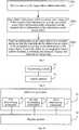
- Fig. 1is a flowchart showing a method for recognizing an object according to an exemplary embodiment. As shown in Fig. 1 , the method for recognizing an object may be applied in a wearable device, which may include but not limited to smart glasses, smart helmet and the like. The method for recognizing an object may include the following steps S101-S102.
- step S101an object to be recognized is determined.
- the wearable devicemay determine the object to be recognized via various manners. For example, a current object may be recognized, and the object to be recognized may be determined by querying a pre-stored objects matching relation table according to information on the current object.
- the usermay wear smart glasses firstly, and then stares at the TV for a time period, for example, three seconds, so that the smart glasses can recognize that the current object is the TV. Then the wearable device can determine the object to be recognized currently by querying an objects matching relation table.
- the objects matching relation tablesaves correspondences between matching objects.
- the userneeds to stare at the current object such as the TV for a time period (for example three seconds or more) so as to improve the recognition efficiency. It is assumed that the user wears the smart glasses and wants to find an object matching an object A, but the user stares at an object B for one second unintentionally. If there is no limitation on the length of the time period for staring but the object is recognized directly, the smart glasses will firstly recognize the object B. This will absolutely decrease the recognition efficiency of the smart glasses.
- the methodmay further include saving the above objects matching relation table.
- step S102when a preset condition is satisfied, the object to be recognized is located and distinctly displayed.
- the preset conditionrefers to a condition for triggering the wearable device to distinctly display an object.
- the preset conditionrefers to that an angle variation of the wearable device exceeds a preset angle threshold which may be flexibly set according to actual requirements.
- the position of the object to be recognizedsuch as the remote controller may be automatically found, and the object may be distinctly displayed at a corresponding position so that the user may find the object timely.
- the corresponding positionmay refer to a position within a preset range from the object.
- the preset rangemay be one centimeter or three centimeters and so on, and specific range may be flexibly set according to factors such as the size of the object.
- the distinct displaying of the objectmay be enlarging the object, or displaying the object with a part of the object enlarged, or flashing the object, i.e., firstly enlarging the object, then shrinking the object and then enlarging the object again.
- the aboveare some examples for distinctly displaying objects, but the present embodiment does not impose limitations on the manners for distinctly displaying of objects.
- Fig. 2when a user cannot find the remote controller of a TV, the user may wear smart glasses 21 and then stare at the TV 22 for a time period such as five seconds. Then, the smart glasses 21 can recognize that the object which the user is currently staring at is the TV 22, and then query an objects matching relation table to determine that the object (i.e., the object that needs to be recognized by the smart glasses) the user wants to find is the remote controller 23 matching with the TV 22.
- the objecti.e., the object that needs to be recognized by the smart glasses
- the smart glasses 21can detect that the angle variation exceeds a preset angle threshold, i.e., the triggering condition for distinctly displaying objects is met, and then the smart glasses 21 can locate the remote controller 23 and display the remote controller 23 in the field of view with the remote controller 23 enlarged.
- a preset angle thresholdi.e., the triggering condition for distinctly displaying objects is met.
- the enlargingmay be as shown in Fig. 2 , for example, a bubble may be popped up at the position where the remote controller 23 is located, and an enlarged remote controller is displayed in the bubble.
- a usermay conveniently and timely find the object her/she wants to find.
- This methodis especially suitable for people with poor vision, or is applicable in scenarios where the user is in an environment in bad light, or where there are relatively many objects nearby the object to be recognized.
- an object to be recognizedis determined, and when a preset condition is satisfied, the object to be recognized is located and distinctly displayed. Thus, a user may find a corresponding object timely.
- the implementations of the embodimentare simple and effective, and thus may help a user find an object that the user wants very conveniently.
- the determining an object to be recognizedincludes:
- the methodmay further include: receiving and saving the objects matching relation table, wherein the objects matching relation table includes correspondences between matching objects.
- the methodmay further include:
- the satisfaction of the preset conditionincludes: detecting that an angle variation of the wearable device exceeds a preset angle threshold.
- the satisfaction of the preset conditionmay include:
- the distinctly displaying the object to be recognizedmay include:
- Fig. 3is a flowchart showing a method for recognizing an object according to an example. As shown in Fig. 3 , the method includes the following steps S301-S303.
- step S301behavior information of a user is obtained and saved.
- the wearable devicefor example smart glasses
- the wearable deviceis capable of receiving behavior information manually input by the user and saving the behavior information, or automatically recording the user's behavior information by time synchronization, GPS location or image recognition and the like.
- the behavior informationmay refer to behaviors relating to a certain object performed by a user at a certain location within a certain time period, for example, a user likes to watch ball games at the living room of his/her home from seven to eleven o'clock every Friday night.
- the behavior informationmay refer to behaviors relating to a certain object performed by a user within a certain time period, or may refer to behaviors relating to a certain object performed by a user at a certain location.
- step S302object information corresponding to time and/or location parameters is obtained according to the pre-stored behavior information, and the object to be recognized corresponding to the time and/or location parameters is determined by querying a pre-stored objects matching relation table according to the object information.
- the wearable devicesuch as smart glasses may obtain object information corresponding to time and/or location parameters according to the pre-stored behavior information. For example, according to the piece of information that "the user likes to watch ball games at the living room of his/her home from seven to eleven o'clock every Friday night" the wearable device may determine that the object information corresponding to the time (i.e., seven to eleven o'clock every Friday night) and the location (i.e., the living room of the home) is the TV, and then may determine that the object to be recognized is the remote controller according to the TV and the objects matching relation table.
- step S303when a preset condition is satisfied, the object to be recognized is located and distinctly displayed.
- the smart glasseswhen the smart glasses detect that a current time reaches a time recorded in the pre-stored behavior information and/or when a current location is a location recorded in the pre-stored behavior information, the smart glasses automatically find the position of the object to be recognized (for example, the remote controller), and then distinctly display the object at a corresponding position so that the user may find the object timely.
- the corresponding positionmay refer to a position within a preset range from the object.
- the preset rangemay be two or four centimeters and so on.
- the distinct displaying of the objectmay be enlarging the object, or displaying the object with a part of the object enlarged, or flashing the object, i.e., firstly enlarging the object, then shrinking the object and then enlarging the object again.
- the wearable devicesuch as smart glasses can distinctly display the object the user wants to find within a particular recorded time according to the behavior information recorded by the user, and thereby help the user conveniently find the object he/she needs.
- Fig. 4is a flowchart showing a method for recognizing an object according to an exemplary embodiment. As shown in Fig. 4 , the method includes the following steps S401-S403.
- step S401the objects matching relation table is received and saved.
- the wearable devicesuch as smart glasses may receive the objects matching relation table input by the user and save the objects matching relation table.
- step S402information on a target object sent from an image recognition device is received, and the object to be recognized is determined by querying the pre-stored objects matching relation table according to the information on the target object.
- the smart glasseswhen a user recognizes an object via a wearable device such as smart glasses, the smart glasses may be incapable of recognizing the object. For example, when the user is smoking, the smart glasses cannot recognize the cigarette.
- the target objectfor example the cigarette
- the smart glassesmay be recognized by other devices, for example image recognition devices such as a camera, and information on the target object may be sent to the smart glasses. After receiving the information on the target object, the smart glasses determine the object to be recognized by querying the above objects matching relation table.
- the wearable devicesuch as smart glasses may recognize a plurality of objects simultaneously.
- the wearable devicemay recognize the object (i.e., a lighter) matching the cigarette by the above method, or may recognize the object (i.e., the remote controller) matching the TV by the embodiments as shown in Fig. 1 or 3 .
- step S403when a preset condition is satisfied, the object to be recognized is located and distinctly displayed.
- the wearable devicewhen an angle variation of the wearable device exceeds a preset angle threshold, for example, 30 degrees, the wearable device automatically finds the position of the object to be recognized (for example the remote controller), and distinctly displays the object at a corresponding position.
- a preset angle thresholdfor example, 30 degrees
- the distinct displaying of the objectmay be displaying the object with the object enlarged, or displaying the object with a part of the object enlarged, or flashing the object, and the like.
- a useris watching TV at the living room with a cigarette 50 in mouth but he cannot find the lighter. Then, the user wears the smart glasses 51 to find the lighter. However, the smart glasses 51 cannot recognize the cigarette, while a camera 52 in the living room can recognize the cigarette 50 and determine that the recognized cigarette 50 is in the target object information table saved by the camera 52. Thus, the camera 52 sends the information on the cigarette 50 to the smart glasses 51 via Bluetooth or WIFI. After receiving the information on the cigarette 50, the smart glasses determine that the object matching the cigarette 50 is the lighter by querying a pre-stored objects matching relation table, and then automatically display the lighter with the lighter enlarged in the field of view.
- the image recognition devicesuch as a camera and smart glasses
- the usermay conveniently find an object he/she wants.
- Fig. 6is a flowchart showing another method for recognizing an object according to an exemplary embodiment.
- the methodmay be applied in an image recognition device, which may include but not limited to a camera.
- the methodmay include the following steps S601-S602.
- step S601information on a target object is obtained.
- the information on a target objectmay refer to objects which the smart glasses cannot recognize, i.e., the objects matching the object to be found, for example, the cigarette in Fig. 5 .
- step S602the information on the target object is sent to a wearable device so that the wearable device determines an object to be recognized according to the information on the target object, locates the object to be recognized when a preset condition is satisfied, and distinctly displays the object to be recognized.
- the image recognition devicemay send the wearable device such as smart glasses the information on the target object via Bluetooth or WIFI, and the like.
- the wearable deviceAfter receiving the information on the target object, the wearable device determines the object to be recognized, and distinctly displays the object.
- the procedures for determining and distinctly displaying the objectare the same as that in the embodiment as shown in Fig. 1 , and detailed descriptions are omitted.
- information on a target objectis obtained; and the information on the target object is sent to a wearable device so that the wearable device determines an object to be recognized according to the information on the target object, locates the object to be recognized when a preset condition is satisfied, and distinctly displays the object to be recognized.
- a usermay find a corresponding object timely.
- the implementations of the embodimentsare simple and effective, and thus may help a user find an object that the user wants very conveniently.
- the obtaining information on a target objectmay include:
- the methodmay further include: receiving and saving the target object information table, wherein the target object information table includes object information matching the object to be recognized.
- Fig. 7is a flowchart showing a method for recognizing an object according to an exemplary embodiment. The method may be applied in a camera and may include the following steps S701-S703.
- step S701the target object information table is received and saved.
- the camerasaves the target object information table for determining whether a recognized object is a target object.
- step S702object information within a current view range is scanned, and if the scanned object information is in the pre-stored target object information table, it is determined that the scanned object information is the information on the target object.
- the camerascans object information within a current view range. It is assumed that the camera finds an object A by scanning. If the object A is in the target object information table, the object A is the target object; otherwise, if the object A is not in the target object information table, the object A is not the target object.
- step S703the information on the target object is sent to a wearable device so that the wearable device determines an object to be recognized according to the information on the target object, locates the object to be recognized when a preset condition is satisfied, and distinctly displays the object to be recognized.
- the camerasends the wearable device such as smart glasses the information on the object A.
- the wearable devicedetermines that the information matching the cigarette is the lighter.
- the smart glassescan display the lighter by flashing.
- information on a target objectis obtained by saving a target object information table; and the information on the target object is sent to a wearable device so that the wearable device determines an object to be recognized according to the information on the target object, locates the object to be recognized when a preset condition is satisfied, and distinctly displays the object to be recognized.
- a usermay find a corresponding object timely.
- the implementations of the embodimentsare simple and effective, and thus may help a user find an object that the user wants very conveniently.
- Fig. 8is a block diagram showing a device for recognizing an object according to an exemplary embodiment.
- the devicemay be applied in a wearable device.
- the device for recognizing an objectincludes a determining module 81 and a display module 82.
- the determining module 81is configured to determine an object to be recognized.
- the display module 82is configured to, when a preset condition is satisfied, locate and distinctly display the object to be recognized which is determined by the determining module 81.
- Fig. 9Ais a block diagram showing another device for recognizing an object according to an exemplary embodiment.
- the determining module 81 as shown in Fig. 9Amay include a first determining submodule 811, a second determining submodule 812 or a third determining submodule 813.
- the first determining submodule 811is configured to recognize a current object, and determine the object to be recognized by querying a pre-stored objects matching relation table according to information on the current object.
- the second determining submodule 812is configured to obtain object information corresponding to time and/or location parameters according to pre-stored behavior information, and determine the object to be recognized corresponding to the time and/or location parameters by querying a pre-stored objects matching relation table according to the object information.
- the third determining submodule 813is configured to receive information on a target object sent from an image recognition device, and determine the object to be recognized by querying a pre-stored objects matching relation table according to the information on the target object.
- Fig. 9Bis a block diagram showing another device for recognizing an object according to an exemplary embodiment.
- the device as shown in Fig. 9Bmay further include a first saving module 83.
- the first saving module 83is configured to, before the determining module 81 determines the object to be recognized, receive and save the objects matching relation table, wherein the objects matching relation table includes correspondences between matching objects.
- Fig. 9Cis a block diagram showing another device for recognizing an object according to an exemplary embodiment.
- the device as shown in Fig. 9Cmay further include a second saving module 84.
- the second saving module 84is configured to, before the second determining submodule 812 obtains object information corresponding to the time and/or location parameters according to the pre-stored behavior information, receive behavior information input by a user, and save the behavior information; or collect behavior information of a user and save the behavior information.
- Fig. 9Dis a block diagram showing another device for recognizing an object according to an exemplary embodiment.
- the display module 82 as shown in Fig. 9Dincludes a first detecting submodule 821 or a second detecting submodule 822.
- the first detecting submodule 821is configured to detect that an angle variation of the wearable device exceeds a preset angle threshold.
- the second detecting submodule 822is configured to detect that a button for distinct display on the wearable device is turned on.
- the display module 82 as shown in Fig. 9Amay also include the first detecting submodule 821 or the second detecting submodule 822, which are not shown in the drawing.
- Fig. 9Eis a block diagram showing another device for recognizing an object according to an exemplary embodiment.
- the display module 82 as shown in Fig. 9Emay include a third detecting submodule 823.
- the third detecting submodule 823is configured to detect that a current time reaches a time recorded in the pre-stored behavior information; and/or detect that a current location corresponds to a location recorded in the pre-stored behavior information.
- Fig. 9Fis a block diagram showing another device for recognizing an object according to an exemplary embodiment.
- the display module 82 as shown in Fig. 9Fmay include a first display submodule 824 or a second display submodule 825.
- the first display submodule 824is configured to display the object to be recognized with a part or all of the object enlarged.
- the second display submodule 825is configured to flash the object to be recognized.
- Fig. 10is a block diagram showing another device for recognizing an object according to an exemplary embodiment. As shown in Fig. 10 , the device for recognizing an object includes an obtaining module 91 and a sending module 92.
- the obtaining module 91is configured to obtain information on a target object.
- the sending module 92is configured to send the information on the target object obtained by the obtaining module to a wearable device so that the wearable device determines an object to be recognized according to the information on the target object, locates the object to be recognized when a preset condition is satisfied, and distinctly displays the object to be recognized.
- Fig. 11Ais a block diagram showing another device for recognizing an object according to an exemplary embodiment.
- the obtaining module 91 as shown in Fig. 11Aincludes a scanning submodule 911 and a determining submodule 912.
- the scanning submodule 911is configured to scan object information within a current view range.
- the determining submodule 912is configured to determine whether object information scanned by the scanning submodule 911 is in a pre-stored target object information table, and if the scanned object information is in the pre-stored target object information table, determine that the scanned object information is the information on the target object.
- Fig. 11Bis a block diagram showing another device for recognizing an object according to an exemplary embodiment.
- the obtaining module 91 as shown in Fig. 11Bmay further include a saving submodule 913.
- the saving submodule 913is configured to, before the determining submodule 912 determines whether scanned object information is in a pre-stored target object information table, receive and save the target object information table, wherein the target object information table includes object information matching the object to be recognized.
- Fig. 12is a block diagram showing a structure applicable in a device for recognizing an object according to an exemplary embodiment.
- the device 1200may be a mobile phone, a computer, a digital broadcast terminal, a messaging device, a gaming console, a tablet, a medical device, exercise equipment, a personal digital assistant, smart glasses or a camera and the like.
- the device 1200may include one or more of the following components: a processing component 1202, a memory 1204, a power component 1206, a multimedia component 1208, an audio component 1210, an input/output (I/O) interface 1212, a sensor component 1214, and a communication component 1216.
- a processing component 1202a memory 1204, a power component 1206, a multimedia component 1208, an audio component 1210, an input/output (I/O) interface 1212, a sensor component 1214, and a communication component 1216.
- the processing component 1202typically controls overall operations of the device 1200, such as the operations associated with display, telephone calls, data communications, camera operations, and recording operations.
- the processing component 1202may include one or more processors 1220 to execute instructions to perform all or part of the steps in the above described methods.
- the processing component 1202may include one or more modules which facilitate the interaction between the processing component 1202 and other components.
- the processing component 1202may include a multimedia module to facilitate the interaction between the multimedia component 1208 and the processing component 1202.
- the memory 1204is configured to store various types of data to support the operation of the device 1200. Examples of such data include instructions for any applications or methods operated on the device 1200, contact data, phonebook data, messages, pictures, video, etc.
- the memory 1204may be implemented using any type of volatile or non-volatile memory devices, or a combination thereof, such as a static random access memory (SRAM), an electrically erasable programmable read-only memory (EEPROM), an erasable programmable read-only memory (EPROM), a programmable read-only memory (PROM), a read-only memory (ROM), a magnetic memory, a flash memory, a magnetic or optical disk.
- SRAMstatic random access memory
- EEPROMelectrically erasable programmable read-only memory
- EPROMerasable programmable read-only memory
- PROMprogrammable read-only memory
- ROMread-only memory
- magnetic memorya magnetic memory
- flash memorya flash memory
- magnetic or optical diska magnetic
- the power component 1206provides power to various components of the device 1200.
- the power component 1206may include a power management system, one or more power sources, and any other components associated with the generation, management, and distribution of power in the device 1200.
- the multimedia component 1208includes a screen providing an output interface between the device 1200 and the user.
- the screenmay include a liquid crystal display (LCD) and a touch panel (TP). If the screen includes the touch panel, the screen may be implemented as a touch screen to receive input signals from the user.
- the touch panelincludes one or more touch sensors to sense touches, swipes, and gestures on the touch panel. The touch sensors may not only sense a boundary of a touch or swipe action, but also sense a period of time and a pressure associated with the touch or swipe action.
- the multimedia component 1208includes a front camera and/or a rear camera. The front camera and the rear camera may receive an external multimedia datum while the device 1200 is in an operation mode, such as a photographing mode or a video mode. Each of the front camera and the rear camera may be a fixed optical lens system or have focus and optical zoom capability.
- the audio component 1210is configured to output and/or input audio signals.
- the audio component 1210includes a microphone ("MIC") configured to receive an external audio signal when the device 1200 is in an operation mode, such as a call mode, a recording mode, and a voice recognition mode.
- the received audio signalmay be further stored in the memory 1204 or transmitted via the communication component 1216.
- the audio component 1210further includes a speaker to output audio signals.
- the I/O interface 1212provides an interface between the processing component 1202 and peripheral interface modules, such as a keyboard, a click wheel, buttons, and the like.
- the buttonsmay include, but are not limited to, a home button, a volume button, a starting button, and a locking button.
- the sensor component 1214includes one or more sensors to provide status assessments of various aspects of the device 1200. For instance, the sensor component 1214 may detect an open/closed status of the device 1200, relative positioning of components, e.g., the display and the keypad, of the device 1200, a change in position of the device 1200 or a component of the device 1200, a presence or absence of user contact with the device 1200, an orientation or an acceleration/deceleration of the device 1200, and a change in temperature of the device 1200.
- the sensor component 1214may include a proximity sensor configured to detect the presence of nearby objects without any physical contact.
- the sensor component 1214may also include a light sensor, such as a CMOS or CCD image sensor, for use in imaging applications.
- the sensor component 1214may also include an accelerometer sensor, a gyroscope sensor, a magnetic sensor, a pressure sensor, or a temperature sensor.
- the communication component 1216is configured to facilitate communication, wired or wirelessly, between the device 1200 and other devices.
- the device 1200can access a wireless network based on a communication standard, such as WiFi, 2G, or 3G, or a combination thereof.
- the communication component 1216receives a broadcast signal or broadcast associated information from an external broadcast management system via a broadcast channel.
- the communication component 1216further includes a near field communication (NFC) module to facilitate short-range communications.
- the NFC modulemay be implemented based on a radio frequency identification (RFID) technology, an infrared data association (IrDA) technology, an ultra-wideband (UWB) technology, a Bluetooth (BT) technology, and other technologies.
- RFIDradio frequency identification
- IrDAinfrared data association
- UWBultra-wideband
- BTBluetooth
- the device 1200may be implemented with one or more application specific integrated circuits (ASICs), digital signal processors (DSPs), digital signal processing devices (DSPDs), programmable logic devices (PLDs), field programmable gate arrays (FPGAs), controllers, micro-controllers, microprocessors, or other electronic components, for performing the above described methods.
- ASICsapplication specific integrated circuits
- DSPsdigital signal processors
- DSPDsdigital signal processing devices
- PLDsprogrammable logic devices
- FPGAsfield programmable gate arrays
- controllersmicro-controllers, microprocessors, or other electronic components, for performing the above described methods.
- non-transitory computer-readable storage mediumincluding instructions, such as included in the memory 1204, executable by the processor 1220 in the device 1200, for performing the above-described methods.
- the non-transitory computer-readable storage mediummay be a ROM, a RAM, a CD-ROM, a magnetic tape, a floppy disc, an optical data storage device, and the like.
Landscapes
- Engineering & Computer Science (AREA)
- Theoretical Computer Science (AREA)
- Physics & Mathematics (AREA)
- General Physics & Mathematics (AREA)
- General Engineering & Computer Science (AREA)
- Data Mining & Analysis (AREA)
- Library & Information Science (AREA)
- Databases & Information Systems (AREA)
- Computer Vision & Pattern Recognition (AREA)
- Artificial Intelligence (AREA)
- Multimedia (AREA)
- Evolutionary Computation (AREA)
- Human Computer Interaction (AREA)
- General Health & Medical Sciences (AREA)
- Software Systems (AREA)
- Medical Informatics (AREA)
- Computing Systems (AREA)
- Life Sciences & Earth Sciences (AREA)
- Bioinformatics & Cheminformatics (AREA)
- Bioinformatics & Computational Biology (AREA)
- Evolutionary Biology (AREA)
- Health & Medical Sciences (AREA)
- User Interface Of Digital Computer (AREA)
- Computer Hardware Design (AREA)
- Radar Systems Or Details Thereof (AREA)
- Eye Examination Apparatus (AREA)
Description
- The present disclosure generally relates to the technical field of wearable devices, and more particularly, to a method and a device for recognizing an object.
- In real life, objects such as remote controllers or fruit knives are frequently used but are often placed carelessly. People sometimes may forget the positions where these objects are placed or these objects may be moved by other persons and cannot be found. This may create unnecessary troubles for users.
- For now, sound activating method is mainly used for finding objects. Specifically, a sound-activated device is disposed on an object, when a trigger condition is satisfied, the sound-activated device on the object is turned on to make sounds. Thus, users can find the object.
- However, such method requires a sound-activated device to be disposed on an object in advance, and if many objects need to be found, increasing number of sound-activated devices need to be disposed. Consequently, the implementations are complicated and inconvenient. Thus, there is an urgent need for a simple and effective method for finding objects.
- Document
US 2013/050258 A1 discloses a device providing an augmented reality image associated with a real world object. The location and visual characteristics of the object are determined by the device and stored in a record. - Document
US 2014/152696 A1 discloses a glass type terminal, a camera mounted on a frame thereof, the terminal being configured to extract information from an image photographed by the camera and to compare this information with related information stored in memory. - Document
EP 2 778 854 A2 discloses a wearable device configured to generate feedback based on an event that occurs in an environment related to the device. - Document
EP 2 865 993 A1 provides a method for discovering an AR (Augmented Reality) object. DocumentUS 2015/042785 A1 discloses a head mounted device to assist an assembling operator on which item he needs to pick highlighting the item in the HMD display. The HMD device, on the basis of a determination of the assembly station in which it is located, determines which item the operator needs to pick according to assembly operations. The determination of the assembly station can be performed by analysing the images of the HMD camera. - Embodiments of the present disclosure provide a method and a device for recognizing an object in order to solve the problem that the existing method for finding objects is complicated and inconvenient.
- According to a first aspect, the invention relates to a method for recognizing an object according to claim 1.
- According to a second aspect, the invention relates to a device for recognizing an object according to claim 4.
- In one particular embodiment, the steps of the method for recognizing an object mentioned above are determined by computer program instructions.
- Consequently, according to a third aspect, the invention is also directed to a computer program for executing the steps of a method for recognizing an object as described above when this program is executed by a computer.
- This program can use any programming language and take the form of source code, object code or a code intermediate between source code and object code, such as a partially compiled form, or any other desirable form.
- The invention is also directed to a computer-readable information medium containing instructions of a computer program as described above.
- The information medium can be any entity or device capable of storing the program. For example, the support can include storage means such as a ROM, for example a CD ROM or a microelectronic circuit ROM, or magnetic storage means, for example a hard disk.
- Alternatively, the information medium can be an integrated circuit in which the program is incorporated, the circuit being adapted to execute the method in question or to be used in its execution.
- The technical solutions provided by embodiments of the present disclosure may have the following advantageous effects:
In the technical solutions provided by embodiments of the present disclosure, an object to be recognized is determined, and when a preset condition is satisfied, the object to be recognized is located and distinctly displayed. Thus, a user may find a corresponding object timely. The implementations of the embodiments are simple and effective, and thus may help a user find an object that the user wants very conveniently. - It is to be understood that both the foregoing general description and the following detailed description are exemplary and explanatory only and are not restrictive of the present disclosure, as claimed.
- The accompanying drawings, which are incorporated in and constitute a part of this specification, illustrate embodiments consistent with the invention and, together with the description, serve to explain the principles of the invention.
Fig. 1 is a flowchart showing a method for recognizing an object according to an exemplary embodiment.Fig. 2 is a schematic diagram showing a scenario for recognizing an object according to an exemplary embodiment.Fig. 3 is a flowchart showing another method for recognizing an object according to an exemplary embodiment.Fig. 4 is a flowchart showing another method for recognizing an object according to an exemplary embodiment.Fig. 5 is a schematic diagram showing a scenario for recognizing an object according to an exemplary embodiment.Fig. 6 is a flowchart showing another method for recognizing an object according to an exemplary embodiment.Fig. 7 is a flowchart showing another method for recognizing an object according to an exemplary embodiment.Fig. 8 is a block diagram showing a device for recognizing an object according to an exemplary embodiment.Fig. 9A is a block diagram showing another device for recognizing an object according to an exemplary embodiment.Fig. 9B is a block diagram showing another device for recognizing an object according to an exemplary embodiment.Fig. 9C is a block diagram showing another device for recognizing an object according to an exemplary embodiment.Fig. 9D is a block diagram showing another device for recognizing an object according to an exemplary embodiment.Fig. 9E is a block diagram showing another device for recognizing an object according to an exemplary embodiment.Fig. 9F is a block diagram showing another device for recognizing an object according to an exemplary embodiment.Fig. 10 is a block diagram showing another device for recognizing an object according to an exemplary embodiment.Fig. 11A is a block diagram showing another device for recognizing an object according to an exemplary embodiment.Fig. 11B a block diagram showing another device for recognizing an object according to an exemplary embodiment.Fig. 12 is a block diagram showing a structure applicable in a device for recognizing an object according to an exemplary embodiment.- Reference will now be made in detail to exemplary embodiments, examples of which are illustrated in the accompanying drawings. The following description refers to the accompanying drawings in which the same numbers in different drawings represent the same or similar elements unless otherwise represented. The implementations set forth in the following description of exemplary embodiments do not represent all implementations consistent with the invention. Instead, they are merely examples of devices and methods consistent with aspects related to the invention as recited in the appended claims.
Fig. 1 is a flowchart showing a method for recognizing an object according to an exemplary embodiment. As shown inFig. 1 , the method for recognizing an object may be applied in a wearable device, which may include but not limited to smart glasses, smart helmet and the like. The method for recognizing an object may include the following steps S101-S102.- In step S101, an object to be recognized is determined.
- In the embodiment, the wearable device may determine the object to be recognized via various manners. For example, a current object may be recognized, and the object to be recognized may be determined by querying a pre-stored objects matching relation table according to information on the current object.
- For example, if a user wants to find the remote controller of a TV, the user may wear smart glasses firstly, and then stares at the TV for a time period, for example, three seconds, so that the smart glasses can recognize that the current object is the TV. Then the wearable device can determine the object to be recognized currently by querying an objects matching relation table. The objects matching relation table saves correspondences between matching objects.
- It shall be noted that the user needs to stare at the current object such as the TV for a time period (for example three seconds or more) so as to improve the recognition efficiency. It is assumed that the user wears the smart glasses and wants to find an object matching an object A, but the user stares at an object B for one second unintentionally. If there is no limitation on the length of the time period for staring but the object is recognized directly, the smart glasses will firstly recognize the object B. This will absolutely decrease the recognition efficiency of the smart glasses.
- Further, before querying the objects matching relation table, the method may further include saving the above objects matching relation table.
- In step S102, when a preset condition is satisfied, the object to be recognized is located and distinctly displayed.
- In the embodiment, the preset condition refers to a condition for triggering the wearable device to distinctly display an object. In the present invention the preset condition refers to that an angle variation of the wearable device exceeds a preset angle threshold which may be flexibly set according to actual requirements.
- When the smart glasses meet the condition for distinctly displaying objects, the position of the object to be recognized such as the remote controller may be automatically found, and the object may be distinctly displayed at a corresponding position so that the user may find the object timely. The corresponding position may refer to a position within a preset range from the object. The preset range may be one centimeter or three centimeters and so on, and specific range may be flexibly set according to factors such as the size of the object. The distinct displaying of the object may be enlarging the object, or displaying the object with a part of the object enlarged, or flashing the object, i.e., firstly enlarging the object, then shrinking the object and then enlarging the object again. The above are some examples for distinctly displaying objects, but the present embodiment does not impose limitations on the manners for distinctly displaying of objects.
- The present disclosure will be illustratively described with reference to
Fig. 2 . As shown inFig. 2 , when a user cannot find the remote controller of a TV, the user may wearsmart glasses 21 and then stare at theTV 22 for a time period such as five seconds. Then, thesmart glasses 21 can recognize that the object which the user is currently staring at is theTV 22, and then query an objects matching relation table to determine that the object (i.e., the object that needs to be recognized by the smart glasses) the user wants to find is theremote controller 23 matching with theTV 22. When the user turns his/her head, thesmart glasses 21 can detect that the angle variation exceeds a preset angle threshold, i.e., the triggering condition for distinctly displaying objects is met, and then thesmart glasses 21 can locate theremote controller 23 and display theremote controller 23 in the field of view with theremote controller 23 enlarged. The enlarging may be as shown inFig. 2 , for example, a bubble may be popped up at the position where theremote controller 23 is located, and an enlarged remote controller is displayed in the bubble. - Thus, by the method, a user may conveniently and timely find the object her/she wants to find. This method is especially suitable for people with poor vision, or is applicable in scenarios where the user is in an environment in bad light, or where there are relatively many objects nearby the object to be recognized.
- In the above embodiment of the method for recognizing an object, an object to be recognized is determined, and when a preset condition is satisfied, the object to be recognized is located and distinctly displayed. Thus, a user may find a corresponding object timely. The implementations of the embodiment are simple and effective, and thus may help a user find an object that the user wants very conveniently.
- In the invention the determining an object to be recognized includes:
- recognizing a current object, and determining the object to be recognized by querying a pre-stored objects matching relation table according to information on the current object; or
- obtaining object information corresponding to time and/or location parameters according to pre-stored behavior information, and determining the object to be recognized corresponding to the time and/or location parameters by querying a pre-stored objects matching relation table according to the object information; or
- receiving information on a target object sent from an image recognition device, and determining the object to be recognized by querying a pre-stored objects matching relation table according to the information on the target object.
- In an embodiment, before the determining an object to be recognized, the method may further include:
receiving and saving the objects matching relation table, wherein the objects matching relation table includes correspondences between matching objects. - In an embodiment, before obtaining object information corresponding to time and/or location parameters according to pre-stored behavior information, the method may further include:
- receiving behavior information input by a user, and saving the behavior information; or
- collecting behavior information of a user and saving the behavior information.
- In the invention the satisfaction of the preset condition includes: detecting that an angle variation of the wearable device exceeds a preset angle threshold.
- In an embodiment, the satisfaction of the preset condition may include:
- detecting that a current time reaches a time recorded in the pre-stored behavior information; and/or
- detecting that a current location corresponds to a location recorded in the pre-stored behavior information.
- In an embodiment, the distinctly displaying the object to be recognized may include:
- displaying the object to be recognized with a part or all of the object enlarged; or
- flashing the object to be recognized.
- As to how to simply and effectively recognize an object, refer to the following embodiments.
- As so far, it can be seen from the above descriptions that the methods provided by the embodiments of the present disclosure can help a user find an object that he/she wants very conveniently.
- Hereinafter, the technical solutions provided by the embodiments of the present disclosure are described with reference to detailed embodiments.
Fig. 3 is a flowchart showing a method for recognizing an object according to an example. As shown inFig. 3 , the method includes the following steps S301-S303.- In step S301, behavior information of a user is obtained and saved.
- In the example, the wearable device (for example smart glasses) is capable of receiving behavior information manually input by the user and saving the behavior information, or automatically recording the user's behavior information by time synchronization, GPS location or image recognition and the like.
- The behavior information may refer to behaviors relating to a certain object performed by a user at a certain location within a certain time period, for example, a user likes to watch ball games at the living room of his/her home from seven to eleven o'clock every Friday night. Or, the behavior information may refer to behaviors relating to a certain object performed by a user within a certain time period, or may refer to behaviors relating to a certain object performed by a user at a certain location.
- In step S302, object information corresponding to time and/or location parameters is obtained according to the pre-stored behavior information, and the object to be recognized corresponding to the time and/or location parameters is determined by querying a pre-stored objects matching relation table according to the object information.
- In the example, the wearable device such as smart glasses may obtain object information corresponding to time and/or location parameters according to the pre-stored behavior information. For example, according to the piece of information that "the user likes to watch ball games at the living room of his/her home from seven to eleven o'clock every Friday night" the wearable device may determine that the object information corresponding to the time (i.e., seven to eleven o'clock every Friday night) and the location (i.e., the living room of the home) is the TV, and then may determine that the object to be recognized is the remote controller according to the TV and the objects matching relation table.
- In step S303, when a preset condition is satisfied, the object to be recognized is located and distinctly displayed.
- In the example, when the smart glasses detect that a current time reaches a time recorded in the pre-stored behavior information and/or when a current location is a location recorded in the pre-stored behavior information, the smart glasses automatically find the position of the object to be recognized (for example, the remote controller), and then distinctly display the object at a corresponding position so that the user may find the object timely. The corresponding position may refer to a position within a preset range from the object. The preset range may be two or four centimeters and so on. The distinct displaying of the object may be enlarging the object, or displaying the object with a part of the object enlarged, or flashing the object, i.e., firstly enlarging the object, then shrinking the object and then enlarging the object again.
- It can be seen from the above descriptions that in the above example, the wearable device such as smart glasses can distinctly display the object the user wants to find within a particular recorded time according to the behavior information recorded by the user, and thereby help the user conveniently find the object he/she needs.
Fig. 4 is a flowchart showing a method for recognizing an object according to an exemplary embodiment. As shown inFig. 4 , the method includes the following steps S401-S403.- In step S401, the objects matching relation table is received and saved.
- In the embodiment, the wearable device such as smart glasses may receive the objects matching relation table input by the user and save the objects matching relation table.
- In step S402, information on a target object sent from an image recognition device is received, and the object to be recognized is determined by querying the pre-stored objects matching relation table according to the information on the target object.
- In the embodiment, when a user recognizes an object via a wearable device such as smart glasses, the smart glasses may be incapable of recognizing the object. For example, when the user is smoking, the smart glasses cannot recognize the cigarette. In order to address this problem, the target object (for example the cigarette) may be recognized by other devices, for example image recognition devices such as a camera, and information on the target object may be sent to the smart glasses. After receiving the information on the target object, the smart glasses determine the object to be recognized by querying the above objects matching relation table.
- It shall be noted that the wearable device such as smart glasses may recognize a plurality of objects simultaneously. For example, the wearable device may recognize the object (i.e., a lighter) matching the cigarette by the above method, or may recognize the object (i.e., the remote controller) matching the TV by the embodiments as shown in
Fig. 1 or3 . - In step S403, when a preset condition is satisfied, the object to be recognized is located and distinctly displayed.
- In the embodiment, when an angle variation of the wearable device exceeds a preset angle threshold, for example, 30 degrees, the wearable device automatically finds the position of the object to be recognized (for example the remote controller), and distinctly displays the object at a corresponding position.
- The distinct displaying of the object may be displaying the object with the object enlarged, or displaying the object with a part of the object enlarged, or flashing the object, and the like.
- The present disclosure will be illustratively described with reference to
Fig. 5 . As shown inFig. 5 , a user is watching TV at the living room with acigarette 50 in mouth but he cannot find the lighter. Then, the user wears thesmart glasses 51 to find the lighter. However, thesmart glasses 51 cannot recognize the cigarette, while acamera 52 in the living room can recognize thecigarette 50 and determine that the recognizedcigarette 50 is in the target object information table saved by thecamera 52. Thus, thecamera 52 sends the information on thecigarette 50 to thesmart glasses 51 via Bluetooth or WIFI. After receiving the information on thecigarette 50, the smart glasses determine that the object matching thecigarette 50 is the lighter by querying a pre-stored objects matching relation table, and then automatically display the lighter with the lighter enlarged in the field of view. - It can be seen that by the image recognition device such as a camera and smart glasses, the user may conveniently find an object he/she wants.
Fig. 6 is a flowchart showing another method for recognizing an object according to an exemplary embodiment. The method may be applied in an image recognition device, which may include but not limited to a camera. The method may include the following steps S601-S602.- In step S601, information on a target object is obtained.
- In the embodiment, the information on a target object may refer to objects which the smart glasses cannot recognize, i.e., the objects matching the object to be found, for example, the cigarette in
Fig. 5 . - In step S602, the information on the target object is sent to a wearable device so that the wearable device determines an object to be recognized according to the information on the target object, locates the object to be recognized when a preset condition is satisfied, and distinctly displays the object to be recognized.
- In the embodiment, after obtaining the information on the target object, the image recognition device may send the wearable device such as smart glasses the information on the target object via Bluetooth or WIFI, and the like.
- After receiving the information on the target object, the wearable device determines the object to be recognized, and distinctly displays the object. The procedures for determining and distinctly displaying the object are the same as that in the embodiment as shown in
Fig. 1 , and detailed descriptions are omitted. - In the above embodiment of the method for recognizing an object, information on a target object is obtained; and the information on the target object is sent to a wearable device so that the wearable device determines an object to be recognized according to the information on the target object, locates the object to be recognized when a preset condition is satisfied, and distinctly displays the object to be recognized. Thus, a user may find a corresponding object timely. The implementations of the embodiments are simple and effective, and thus may help a user find an object that the user wants very conveniently.
- In an embodiment, the obtaining information on a target object may include:
- scanning object information within a current view range; and
- determining whether scanned object information is in a pre-stored target object information table, and if the scanned object information is in the pre-stored target object information table, determining that the scanned object information is the information on the target object.
- In an embodiment, before determining whether scanned object information is in a pre-stored target object information table, the method may further include:
receiving and saving the target object information table, wherein the target object information table includes object information matching the object to be recognized. Fig. 7 is a flowchart showing a method for recognizing an object according to an exemplary embodiment. The method may be applied in a camera and may include the following steps S701-S703.- In step S701, the target object information table is received and saved.
- In the embodiment, the camera saves the target object information table for determining whether a recognized object is a target object.
- In step S702, object information within a current view range is scanned, and if the scanned object information is in the pre-stored target object information table, it is determined that the scanned object information is the information on the target object.
- In the embodiment, the camera scans object information within a current view range. It is assumed that the camera finds an object A by scanning. If the object A is in the target object information table, the object A is the target object; otherwise, if the object A is not in the target object information table, the object A is not the target object.
- In step S703, the information on the target object is sent to a wearable device so that the wearable device determines an object to be recognized according to the information on the target object, locates the object to be recognized when a preset condition is satisfied, and distinctly displays the object to be recognized.
- In the embodiment, after determining that the object A is the target object, the camera sends the wearable device such as smart glasses the information on the object A. After receiving the information on the object A (for example, the cigarette), the wearable device determines that the information matching the cigarette is the lighter. When the user turns his/her head, i.e., the angle variation of the smart glasses is greater than a preset angle threshold, the smart glasses can display the lighter by flashing.
- In the above embodiments of methods for recognizing an object, information on a target object is obtained by saving a target object information table; and the information on the target object is sent to a wearable device so that the wearable device determines an object to be recognized according to the information on the target object, locates the object to be recognized when a preset condition is satisfied, and distinctly displays the object to be recognized. Thus, a user may find a corresponding object timely. The implementations of the embodiments are simple and effective, and thus may help a user find an object that the user wants very conveniently.
Fig. 8 is a block diagram showing a device for recognizing an object according to an exemplary embodiment. The device may be applied in a wearable device. As shown inFig. 8 , the device for recognizing an object includes a determiningmodule 81 and adisplay module 82.- The determining
module 81 is configured to determine an object to be recognized. - The
display module 82 is configured to, when a preset condition is satisfied, locate and distinctly display the object to be recognized which is determined by the determiningmodule 81. Fig. 9A is a block diagram showing another device for recognizing an object according to an exemplary embodiment. On the basis of the embodiment as shown inFig. 8 , the determiningmodule 81 as shown inFig. 9A may include a first determiningsubmodule 811, a second determiningsubmodule 812 or a third determiningsubmodule 813.- The first determining
submodule 811 is configured to recognize a current object, and determine the object to be recognized by querying a pre-stored objects matching relation table according to information on the current object. - The second determining
submodule 812 is configured to obtain object information corresponding to time and/or location parameters according to pre-stored behavior information, and determine the object to be recognized corresponding to the time and/or location parameters by querying a pre-stored objects matching relation table according to the object information. - The third determining
submodule 813 is configured to receive information on a target object sent from an image recognition device, and determine the object to be recognized by querying a pre-stored objects matching relation table according to the information on the target object. Fig. 9B is a block diagram showing another device for recognizing an object according to an exemplary embodiment. On the basis of the embodiment as shown inFig. 9A , the device as shown inFig. 9B may further include afirst saving module 83.- The
first saving module 83 is configured to, before the determiningmodule 81 determines the object to be recognized, receive and save the objects matching relation table, wherein the objects matching relation table includes correspondences between matching objects. Fig. 9C is a block diagram showing another device for recognizing an object according to an exemplary embodiment. On the basis of the embodiment as shown inFig. 9A , the device as shown inFig. 9C may further include asecond saving module 84.- The
second saving module 84 is configured to, before the second determiningsubmodule 812 obtains object information corresponding to the time and/or location parameters according to the pre-stored behavior information, receive behavior information input by a user, and save the behavior information; or collect behavior information of a user and save the behavior information. Fig. 9D is a block diagram showing another device for recognizing an object according to an exemplary embodiment. On the basis of the embodiment as shown inFig. 8 , thedisplay module 82 as shown inFig. 9D includes a first detectingsubmodule 821 or a second detectingsubmodule 822.- The first detecting
submodule 821 is configured to detect that an angle variation of the wearable device exceeds a preset angle threshold. - The second detecting
submodule 822 is configured to detect that a button for distinct display on the wearable device is turned on. - Further, the
display module 82 as shown inFig. 9A may also include the first detectingsubmodule 821 or the second detectingsubmodule 822, which are not shown in the drawing. Fig. 9E is a block diagram showing another device for recognizing an object according to an exemplary embodiment. On the basis of the embodiment as shown inFig. 9C , thedisplay module 82 as shown inFig. 9E may include a third detectingsubmodule 823.- The third detecting
submodule 823 is configured to detect that a current time reaches a time recorded in the pre-stored behavior information; and/or detect that a current location corresponds to a location recorded in the pre-stored behavior information. Fig. 9F is a block diagram showing another device for recognizing an object according to an exemplary embodiment. On the basis of the embodiment as shown inFig. 8 , thedisplay module 82 as shown inFig. 9F may include afirst display submodule 824 or asecond display submodule 825.- The
first display submodule 824 is configured to display the object to be recognized with a part or all of the object enlarged. - The
second display submodule 825 is configured to flash the object to be recognized. Fig. 10 is a block diagram showing another device for recognizing an object according to an exemplary embodiment. As shown inFig. 10 , the device for recognizing an object includes an obtainingmodule 91 and a sendingmodule 92.- The obtaining
module 91 is configured to obtain information on a target object. - The sending
module 92 is configured to send the information on the target object obtained by the obtaining module to a wearable device so that the wearable device determines an object to be recognized according to the information on the target object, locates the object to be recognized when a preset condition is satisfied, and distinctly displays the object to be recognized. Fig. 11A is a block diagram showing another device for recognizing an object according to an exemplary embodiment. On the basis of the embodiment as shown inFig. 10 , the obtainingmodule 91 as shown inFig. 11A includes ascanning submodule 911 and a determiningsubmodule 912.- The
scanning submodule 911 is configured to scan object information within a current view range. - The determining
submodule 912 is configured to determine whether object information scanned by thescanning submodule 911 is in a pre-stored target object information table, and if the scanned object information is in the pre-stored target object information table, determine that the scanned object information is the information on the target object. Fig. 11B is a block diagram showing another device for recognizing an object according to an exemplary embodiment. On the basis of the embodiment as shown inFig. 11A , the obtainingmodule 91 as shown inFig. 11B may further include a savingsubmodule 913.- The saving
submodule 913 is configured to, before the determiningsubmodule 912 determines whether scanned object information is in a pre-stored target object information table, receive and save the target object information table, wherein the target object information table includes object information matching the object to be recognized. - With respect to the devices in the above embodiments, the specific manners for performing operations for individual modules/submodules therein have been described in detail in the embodiments regarding the methods, which will not be elaborated herein.
Fig. 12 is a block diagram showing a structure applicable in a device for recognizing an object according to an exemplary embodiment. For example, thedevice 1200 may be a mobile phone, a computer, a digital broadcast terminal, a messaging device, a gaming console, a tablet, a medical device, exercise equipment, a personal digital assistant, smart glasses or a camera and the like.- Referring to
Fig. 12 , thedevice 1200 may include one or more of the following components: aprocessing component 1202, amemory 1204, apower component 1206, amultimedia component 1208, anaudio component 1210, an input/output (I/O)interface 1212, asensor component 1214, and acommunication component 1216. - The
processing component 1202 typically controls overall operations of thedevice 1200, such as the operations associated with display, telephone calls, data communications, camera operations, and recording operations. Theprocessing component 1202 may include one ormore processors 1220 to execute instructions to perform all or part of the steps in the above described methods. Moreover, theprocessing component 1202 may include one or more modules which facilitate the interaction between theprocessing component 1202 and other components. For instance, theprocessing component 1202 may include a multimedia module to facilitate the interaction between themultimedia component 1208 and theprocessing component 1202. - The
memory 1204 is configured to store various types of data to support the operation of thedevice 1200. Examples of such data include instructions for any applications or methods operated on thedevice 1200, contact data, phonebook data, messages, pictures, video, etc. Thememory 1204 may be implemented using any type of volatile or non-volatile memory devices, or a combination thereof, such as a static random access memory (SRAM), an electrically erasable programmable read-only memory (EEPROM), an erasable programmable read-only memory (EPROM), a programmable read-only memory (PROM), a read-only memory (ROM), a magnetic memory, a flash memory, a magnetic or optical disk. - The
power component 1206 provides power to various components of thedevice 1200. Thepower component 1206 may include a power management system, one or more power sources, and any other components associated with the generation, management, and distribution of power in thedevice 1200. - The
multimedia component 1208 includes a screen providing an output interface between thedevice 1200 and the user. In some embodiments, the screen may include a liquid crystal display (LCD) and a touch panel (TP). If the screen includes the touch panel, the screen may be implemented as a touch screen to receive input signals from the user. The touch panel includes one or more touch sensors to sense touches, swipes, and gestures on the touch panel. The touch sensors may not only sense a boundary of a touch or swipe action, but also sense a period of time and a pressure associated with the touch or swipe action. In some embodiments, themultimedia component 1208 includes a front camera and/or a rear camera. The front camera and the rear camera may receive an external multimedia datum while thedevice 1200 is in an operation mode, such as a photographing mode or a video mode. Each of the front camera and the rear camera may be a fixed optical lens system or have focus and optical zoom capability. - The
audio component 1210 is configured to output and/or input audio signals. For example, theaudio component 1210 includes a microphone ("MIC") configured to receive an external audio signal when thedevice 1200 is in an operation mode, such as a call mode, a recording mode, and a voice recognition mode. The received audio signal may be further stored in thememory 1204 or transmitted via thecommunication component 1216. In some embodiments, theaudio component 1210 further includes a speaker to output audio signals. - The I/
O interface 1212 provides an interface between theprocessing component 1202 and peripheral interface modules, such as a keyboard, a click wheel, buttons, and the like. The buttons may include, but are not limited to, a home button, a volume button, a starting button, and a locking button. - The
sensor component 1214 includes one or more sensors to provide status assessments of various aspects of thedevice 1200. For instance, thesensor component 1214 may detect an open/closed status of thedevice 1200, relative positioning of components, e.g., the display and the keypad, of thedevice 1200, a change in position of thedevice 1200 or a component of thedevice 1200, a presence or absence of user contact with thedevice 1200, an orientation or an acceleration/deceleration of thedevice 1200, and a change in temperature of thedevice 1200. Thesensor component 1214 may include a proximity sensor configured to detect the presence of nearby objects without any physical contact. Thesensor component 1214 may also include a light sensor, such as a CMOS or CCD image sensor, for use in imaging applications. In some embodiments, thesensor component 1214 may also include an accelerometer sensor, a gyroscope sensor, a magnetic sensor, a pressure sensor, or a temperature sensor. - The
communication component 1216 is configured to facilitate communication, wired or wirelessly, between thedevice 1200 and other devices. Thedevice 1200 can access a wireless network based on a communication standard, such as WiFi, 2G, or 3G, or a combination thereof. In one exemplary embodiment, thecommunication component 1216 receives a broadcast signal or broadcast associated information from an external broadcast management system via a broadcast channel. In one exemplary embodiment, thecommunication component 1216 further includes a near field communication (NFC) module to facilitate short-range communications. For example, the NFC module may be implemented based on a radio frequency identification (RFID) technology, an infrared data association (IrDA) technology, an ultra-wideband (UWB) technology, a Bluetooth (BT) technology, and other technologies. - In exemplary embodiments, the
device 1200 may be implemented with one or more application specific integrated circuits (ASICs), digital signal processors (DSPs), digital signal processing devices (DSPDs), programmable logic devices (PLDs), field programmable gate arrays (FPGAs), controllers, micro-controllers, microprocessors, or other electronic components, for performing the above described methods. - In exemplary embodiments, there is also provided a non-transitory computer-readable storage medium including instructions, such as included in the
memory 1204, executable by theprocessor 1220 in thedevice 1200, for performing the above-described methods. For example, the non-transitory computer-readable storage medium may be a ROM, a RAM, a CD-ROM, a magnetic tape, a floppy disc, an optical data storage device, and the like.
Claims (6)
- A method for recognizing an object, wherein the method is applied in a wearable device that is suitable to be worn on the head of a user, the method comprising:determining (S101) an object to be recognized; andwhen a preset condition is satisfied, locating (S102) and distinctly displaying the object to be recognized on a display of the wearable device at a position within a preset range from the object to be recognized, wherein the step of determining (S101) an object to be recognized comprises:recognizing a current object by the wearable device by determining that the user wearing the wearable device stares at the current object for a time period, and determining the object to be recognized by querying a pre-stored objects matching relation table according to information on the current object; orreceiving information on a target object sent from an image recognition device, and determining the object to be recognized by querying a pre-stored objects matching relation table according to the information on the target object;the method beingcharacterized in that the satisfaction of the preset condition comprises:
detecting, after the step of determining (S101) the object to be recognized, that an angle variation of the wearable device exceeds a preset angle threshold when the user wearing the wearable device turns his head. - The method for recognizing an object according to claim 1, wherein before the step of determining (S101) an object to be recognized, the method further comprises:
receiving (S701) and saving the objects matching relation table, wherein the objects matching relation table comprises correspondences between matching objects. - The method for recognizing an object according to any one of claims 1 to 2, wherein the distinctly displaying the object to be recognized comprises:
displaying the object to be recognized with a part or all of the object enlarged; or flashing the object to be recognized. - A device for recognizing an object, wherein the device is applied in a wearable device that is suitable to be mounted on the head of a user, the device for recognizing an object comprising:a determining module (81) configured to determine an object to be recognized; anda display module (82) configured to, when a preset condition is satisfied, locate and distinctly display the object to be recognized at a position within a preset range from the object to be recognized wherein the determining module (81) comprises:a first determining submodule (811) configured to recognize a current object by determining that the user wearing the wearable device stares at the current object for a time period, and determine the object to be recognized by querying a pre-stored objects matching relation table according to information on the current object; ora third determining submodule (813) configured to receive information on a target object sent from an image recognition device, and determine the object to be recognized by querying a pre-stored objects matching relation table according to the information on the target object;the device beingcharacterized in that the display module (82) comprises:
a first detecting submodule (821) configured to detect, after the first determining submodule (811) determines the object to be recognized, that an angle variation of the wearable device exceeds a preset angle threshold when the user wearing the wearable device turns his head, so as to determine that the preset condition is satisfied. - The device for recognizing an object according to claim 4, further comprising:
a first saving module (83) configured to, before the determining module (81) determines the object to be recognized, receive and save the objects matching relation table, wherein the objects matching relation table comprises correspondences between matching objects. - A computer program, which when executing on a processor, performs a method according to any one of claims 1 to 3.
Applications Claiming Priority (1)
| Application Number | Priority Date | Filing Date | Title |
|---|---|---|---|
| CN201510253929.XACN104850229B (en) | 2015-05-18 | 2015-05-18 | Identify the method and device of object |
Publications (3)
| Publication Number | Publication Date |
|---|---|
| EP3096209A2 EP3096209A2 (en) | 2016-11-23 |
| EP3096209A3 EP3096209A3 (en) | 2017-02-22 |
| EP3096209B1true EP3096209B1 (en) | 2020-02-12 |
Family
ID=53849925
Family Applications (1)
| Application Number | Title | Priority Date | Filing Date |
|---|---|---|---|
| EP16169063.1AActiveEP3096209B1 (en) | 2015-05-18 | 2016-05-10 | Method and device for recognizing object |
Country Status (8)
| Country | Link |
|---|---|
| US (1) | US10133957B2 (en) |
| EP (1) | EP3096209B1 (en) |
| JP (1) | JP6326552B2 (en) |
| KR (1) | KR101758648B1 (en) |
| CN (1) | CN104850229B (en) |
| MX (1) | MX357003B (en) |
| RU (1) | RU2642391C2 (en) |
| WO (1) | WO2016184104A1 (en) |
Families Citing this family (16)
| Publication number | Priority date | Publication date | Assignee | Title |
|---|---|---|---|---|
| CN104850229B (en) | 2015-05-18 | 2019-03-22 | 小米科技有限责任公司 | Identify the method and device of object |
| CN113407743B (en)* | 2016-04-08 | 2024-11-05 | 北京三星通信技术研究有限公司 | Object information translation and derived information acquisition method and device |
| CN105928504B (en)* | 2016-04-14 | 2018-03-20 | 北京小米移动软件有限公司 | Barrier localization method, apparatus and system |
| CN106200786B (en)* | 2016-06-29 | 2020-05-26 | 联想(北京)有限公司 | Information processing method and wearable electronic equipment |
| CN106294558A (en)* | 2016-07-26 | 2017-01-04 | 北京小米移动软件有限公司 | Object positioning method and device |
| CN106897665B (en)* | 2017-01-17 | 2020-08-18 | 北京光年无限科技有限公司 | Object identification method and system applied to intelligent robot |
| US9998790B1 (en) | 2017-03-30 | 2018-06-12 | Rovi Guides, Inc. | Augmented reality content recommendation |
| DE102017207470A1 (en)* | 2017-05-04 | 2018-11-08 | BSH Hausgeräte GmbH | System with a cold room and with an output unit |
| CN110796704A (en)* | 2018-08-01 | 2020-02-14 | 中兴通讯股份有限公司 | Auxiliary recording method and device based on monitoring camera and storage medium |
| CN110955325A (en)* | 2018-09-26 | 2020-04-03 | 上海肇观电子科技有限公司 | Intelligent glasses focus tracking method and device, intelligent glasses and storage medium |
| US10860165B2 (en) | 2018-09-26 | 2020-12-08 | NextVPU (Shanghai) Co., Ltd. | Tracking method and apparatus for smart glasses, smart glasses and storage medium |
| CN110955043B (en)* | 2018-09-26 | 2024-06-18 | 上海肇观电子科技有限公司 | Intelligent glasses focus tracking method and device, intelligent glasses and storage medium |
| KR102242719B1 (en)* | 2018-09-26 | 2021-04-23 | 넥스트브이피유 (상하이) 코포레이트 리미티드 | Smart glasses tracking method and device, and smart glasses and storage media |
| CN111814510B (en)* | 2019-04-10 | 2024-04-05 | 杭州海康威视数字技术股份有限公司 | Method and device for detecting legacy host |
| CN113537205A (en)* | 2020-04-21 | 2021-10-22 | 中兴通讯股份有限公司 | Image recognition method, system, terminal, server and storage medium |
| US11933621B2 (en)* | 2021-10-06 | 2024-03-19 | Qualcomm Incorporated | Providing a location of an object of interest |
Citations (1)
| Publication number | Priority date | Publication date | Assignee | Title |
|---|---|---|---|---|
| US20150042785A1 (en)* | 2013-08-08 | 2015-02-12 | Nissan North America, Inc. | Wearable Assembly Aid |
Family Cites Families (34)
| Publication number | Priority date | Publication date | Assignee | Title |
|---|---|---|---|---|
| ES2885435T3 (en)* | 2001-04-30 | 2021-12-13 | Activemap Llc | Interactive map submitted electronically |
| US7319877B2 (en)* | 2003-07-22 | 2008-01-15 | Microsoft Corporation | Methods for determining the approximate location of a device from ambient signals |
| JP2007018456A (en)* | 2005-07-11 | 2007-01-25 | Nikon Corp | Information display device and information display method |
| US20080147730A1 (en)* | 2006-12-18 | 2008-06-19 | Motorola, Inc. | Method and system for providing location-specific image information |
| DE102007022888B3 (en)* | 2007-05-14 | 2008-11-27 | Olympus Winter & Ibe Gmbh | Method and device for image processing of endoscope images |
| US9571625B2 (en)* | 2009-08-11 | 2017-02-14 | Lg Electronics Inc. | Electronic device and control method thereof |
| US8239130B1 (en)* | 2009-11-12 | 2012-08-07 | Google Inc. | Enhanced identification of interesting points-of-interest |
| WO2011106797A1 (en)* | 2010-02-28 | 2011-09-01 | Osterhout Group, Inc. | Projection triggering through an external marker in an augmented reality eyepiece |
| CA2736694A1 (en)* | 2010-04-08 | 2011-10-08 | Douglas Watson | Item finder system for finding items stored in storage regions |
| KR101357262B1 (en)* | 2010-08-13 | 2014-01-29 | 주식회사 팬택 | Apparatus and Method for Recognizing Object using filter information |
| KR101337555B1 (en) | 2010-09-09 | 2013-12-16 | 주식회사 팬택 | Method and Apparatus for Providing Augmented Reality using Relation between Objects |
| US9013550B2 (en)* | 2010-09-09 | 2015-04-21 | Qualcomm Incorporated | Online reference generation and tracking for multi-user augmented reality |
| US8174931B2 (en)* | 2010-10-08 | 2012-05-08 | HJ Laboratories, LLC | Apparatus and method for providing indoor location, position, or tracking of a mobile computer using building information |
| JP5870929B2 (en)* | 2010-11-02 | 2016-03-01 | 日本電気株式会社 | Information processing system, information processing apparatus, and information processing method |
| CN103415849B (en) | 2010-12-21 | 2019-11-15 | 高通股份有限公司 | For marking the Computerized method and equipment of at least one feature of view image |
| US8203605B1 (en)* | 2011-05-11 | 2012-06-19 | Google Inc. | Point-of-view object selection |
| US9342610B2 (en)* | 2011-08-25 | 2016-05-17 | Microsoft Technology Licensing, Llc | Portals: registered objects as virtualized, personalized displays |
| EP2795420A4 (en)* | 2011-12-19 | 2015-07-08 | Birds In The Hand Llc | Method and system for sharing object information |
| US9407860B2 (en)* | 2012-04-06 | 2016-08-02 | Melvin Lee Barnes, JR. | System, method and computer program product for processing image data |
| US9035970B2 (en)* | 2012-06-29 | 2015-05-19 | Microsoft Technology Licensing, Llc | Constraint based information inference |
| US9443414B2 (en)* | 2012-08-07 | 2016-09-13 | Microsoft Technology Licensing, Llc | Object tracking |
| JP5787099B2 (en)* | 2012-11-06 | 2015-09-30 | コニカミノルタ株式会社 | Guidance information display device |
| CN102981616B (en)* | 2012-11-06 | 2017-09-22 | 中兴通讯股份有限公司 | The recognition methods of object and system and computer in augmented reality |
| KR20140072651A (en) | 2012-12-05 | 2014-06-13 | 엘지전자 주식회사 | Glass Type Mobile Terminal |
| CN103968824B (en) | 2013-01-28 | 2018-04-10 | 华为终端(东莞)有限公司 | One kind finds augmented reality mesh calibration method and terminal |
| US9092954B2 (en) | 2013-03-15 | 2015-07-28 | Immersion Corporation | Wearable haptic device |
| JP6222440B2 (en)* | 2013-10-07 | 2017-11-01 | コニカミノルタ株式会社 | AR display system, AR display device, information processing device, and program |
| US20150134689A1 (en)* | 2013-11-08 | 2015-05-14 | Google Inc. | Image based location determination |
| CN103617418A (en)* | 2013-11-28 | 2014-03-05 | 小米科技有限责任公司 | Method, device and terminal equipment for biology recognition |
| US9631933B1 (en)* | 2014-05-23 | 2017-04-25 | Google Inc. | Specifying unavailable locations for autonomous vehicles |
| US9386401B2 (en)* | 2014-08-25 | 2016-07-05 | Steven K. Gold | Proximity-based sensing, communicating, and processing of user physiologic information |
| CN104317815A (en)* | 2014-09-26 | 2015-01-28 | 英业达科技有限公司 | Wearable device capable of finding objects and object finding method |
| CN204595327U (en)* | 2014-12-26 | 2015-08-26 | 成都理想境界科技有限公司 | Head-mounted display apparatus |
| CN104850229B (en)* | 2015-05-18 | 2019-03-22 | 小米科技有限责任公司 | Identify the method and device of object |
- 2015
- 2015-05-18CNCN201510253929.XApatent/CN104850229B/enactiveActive
- 2015-12-24KRKR1020167004130Apatent/KR101758648B1/enactiveActive
- 2015-12-24MXMX2016004985Apatent/MX357003B/enactiveIP Right Grant
- 2015-12-24WOPCT/CN2015/098717patent/WO2016184104A1/ennot_activeCeased
- 2015-12-24JPJP2017518406Apatent/JP6326552B2/enactiveActive
- 2015-12-24RURU2016115038Apatent/RU2642391C2/enactive
- 2016
- 2016-05-10EPEP16169063.1Apatent/EP3096209B1/enactiveActive
- 2016-05-16USUS15/155,385patent/US10133957B2/enactiveActive
Patent Citations (1)
| Publication number | Priority date | Publication date | Assignee | Title |
|---|---|---|---|---|
| US20150042785A1 (en)* | 2013-08-08 | 2015-02-12 | Nissan North America, Inc. | Wearable Assembly Aid |
Also Published As
| Publication number | Publication date |
|---|---|
| EP3096209A2 (en) | 2016-11-23 |
| US10133957B2 (en) | 2018-11-20 |
| KR101758648B1 (en) | 2017-07-17 |
| MX2016004985A (en) | 2017-03-07 |
| CN104850229B (en) | 2019-03-22 |
| US20160342858A1 (en) | 2016-11-24 |
| WO2016184104A1 (en) | 2016-11-24 |
| RU2016115038A (en) | 2017-10-24 |
| RU2642391C2 (en) | 2018-01-24 |
| CN104850229A (en) | 2015-08-19 |
| MX357003B (en) | 2018-06-22 |
| KR20160147249A (en) | 2016-12-22 |
| JP6326552B2 (en) | 2018-05-16 |
| EP3096209A3 (en) | 2017-02-22 |
| JP2017526089A (en) | 2017-09-07 |
Similar Documents
| Publication | Publication Date | Title |
|---|---|---|
| EP3096209B1 (en) | Method and device for recognizing object | |
| US10191564B2 (en) | Screen control method and device | |
| EP3413549B1 (en) | Method and device for displaying notification information | |
| US10175671B2 (en) | Method and apparatus for controlling intelligent device | |
| EP3179711B1 (en) | Method and apparatus for preventing photograph from being shielded | |
| US20170091551A1 (en) | Method and apparatus for controlling electronic device | |
| US9685001B2 (en) | System and method for indicating a presence of supplemental information in augmented reality | |
| EP3249509A1 (en) | Method and device for playing live videos | |
| US10025393B2 (en) | Button operation processing method in single-hand mode | |
| US20170034409A1 (en) | Method, device, and computer-readable medium for image photographing | |
| EP3076640A1 (en) | Method, apparatus for controlling state of terminal screen, and electronic device | |
| US9983667B2 (en) | Method and apparatus for display control, electronic device | |
| EP3099063A1 (en) | Video communication method and apparatus | |
| EP3048526B1 (en) | Voice prompting method and apparatus | |
| US20170154604A1 (en) | Method and apparatus for adjusting luminance | |
| EP3173970A1 (en) | Image processing method and apparatus | |
| US20170064182A1 (en) | Method and device for acquiring image file | |
| EP3299946B1 (en) | Method and device for switching environment picture | |
| EP3024211B1 (en) | Method and device for announcing voice call | |
| US20170344177A1 (en) | Method and device for determining operation mode of terminal | |
| EP3322227B1 (en) | Methods and apparatuses for controlling wireless connection, computer program and recording medium | |
| EP3015965A1 (en) | Method and apparatus for prompting device connection | |
| EP3460634A1 (en) | Method and device for displaying an input interface and an electronic device | |
| US20170289306A1 (en) | Method, device and storage medium for synchronizing states | |
| CN107657235A (en) | Recognition methods and device based on augmented reality |
Legal Events
| Date | Code | Title | Description |
|---|---|---|---|
| PUAI | Public reference made under article 153(3) epc to a published international application that has entered the european phase | Free format text:ORIGINAL CODE: 0009012 | |
| AK | Designated contracting states | Kind code of ref document:A2 Designated state(s):AL AT BE BG CH CY CZ DE DK EE ES FI FR GB GR HR HU IE IS IT LI LT LU LV MC MK MT NL NO PL PT RO RS SE SI SK SM TR | |
| AX | Request for extension of the european patent | Extension state:BA ME | |
| PUAL | Search report despatched | Free format text:ORIGINAL CODE: 0009013 | |
| AK | Designated contracting states | Kind code of ref document:A3 Designated state(s):AL AT BE BG CH CY CZ DE DK EE ES FI FR GB GR HR HU IE IS IT LI LT LU LV MC MK MT NL NO PL PT RO RS SE SI SK SM TR | |
| AX | Request for extension of the european patent | Extension state:BA ME | |
| RIC1 | Information provided on ipc code assigned before grant | Ipc:G06F 3/01 20060101AFI20170113BHEP Ipc:G06K 9/00 20060101ALI20170113BHEP | |
| STAA | Information on the status of an ep patent application or granted ep patent | Free format text:STATUS: REQUEST FOR EXAMINATION WAS MADE | |
| 17P | Request for examination filed | Effective date:20170822 | |
| RBV | Designated contracting states (corrected) | Designated state(s):AL AT BE BG CH CY CZ DE DK EE ES FI FR GB GR HR HU IE IS IT LI LT LU LV MC MK MT NL NO PL PT RO RS SE SI SK SM TR | |
| STAA | Information on the status of an ep patent application or granted ep patent | Free format text:STATUS: EXAMINATION IS IN PROGRESS | |
| 17Q | First examination report despatched | Effective date:20180103 | |
| GRAP | Despatch of communication of intention to grant a patent | Free format text:ORIGINAL CODE: EPIDOSNIGR1 | |
| STAA | Information on the status of an ep patent application or granted ep patent | Free format text:STATUS: GRANT OF PATENT IS INTENDED | |
| RIC1 | Information provided on ipc code assigned before grant | Ipc:G06K 9/00 20060101ALI20190913BHEP Ipc:G06F 16/58 20190101ALI20190913BHEP Ipc:G06F 3/01 20060101AFI20190913BHEP Ipc:G06K 9/62 20060101ALI20190913BHEP Ipc:G06F 16/583 20190101ALI20190913BHEP | |
| INTG | Intention to grant announced | Effective date:20191007 | |
| GRAS | Grant fee paid | Free format text:ORIGINAL CODE: EPIDOSNIGR3 | |
| GRAA | (expected) grant | Free format text:ORIGINAL CODE: 0009210 | |
| STAA | Information on the status of an ep patent application or granted ep patent | Free format text:STATUS: THE PATENT HAS BEEN GRANTED | |
| AK | Designated contracting states | Kind code of ref document:B1 Designated state(s):AL AT BE BG CH CY CZ DE DK EE ES FI FR GB GR HR HU IE IS IT LI LT LU LV MC MK MT NL NO PL PT RO RS SE SI SK SM TR | |
| REG | Reference to a national code | Ref country code:GB Ref legal event code:FG4D | |
| REG | Reference to a national code | Ref country code:CH Ref legal event code:EP | |
| REG | Reference to a national code | Ref country code:AT Ref legal event code:REF Ref document number:1232989 Country of ref document:AT Kind code of ref document:T Effective date:20200215 | |
| REG | Reference to a national code | Ref country code:IE Ref legal event code:FG4D | |
| REG | Reference to a national code | Ref country code:DE Ref legal event code:R096 Ref document number:602016029360 Country of ref document:DE | |
| PG25 | Lapsed in a contracting state [announced via postgrant information from national office to epo] | Ref country code:NO Free format text:LAPSE BECAUSE OF FAILURE TO SUBMIT A TRANSLATION OF THE DESCRIPTION OR TO PAY THE FEE WITHIN THE PRESCRIBED TIME-LIMIT Effective date:20200512 Ref country code:RS Free format text:LAPSE BECAUSE OF FAILURE TO SUBMIT A TRANSLATION OF THE DESCRIPTION OR TO PAY THE FEE WITHIN THE PRESCRIBED TIME-LIMIT Effective date:20200212 Ref country code:FI Free format text:LAPSE BECAUSE OF FAILURE TO SUBMIT A TRANSLATION OF THE DESCRIPTION OR TO PAY THE FEE WITHIN THE PRESCRIBED TIME-LIMIT Effective date:20200212 | |
| REG | Reference to a national code | Ref country code:LT Ref legal event code:MG4D | |
| REG | Reference to a national code | Ref country code:NL Ref legal event code:MP Effective date:20200212 | |
| PG25 | Lapsed in a contracting state [announced via postgrant information from national office to epo] | Ref country code:IS Free format text:LAPSE BECAUSE OF FAILURE TO SUBMIT A TRANSLATION OF THE DESCRIPTION OR TO PAY THE FEE WITHIN THE PRESCRIBED TIME-LIMIT Effective date:20200612 Ref country code:HR Free format text:LAPSE BECAUSE OF FAILURE TO SUBMIT A TRANSLATION OF THE DESCRIPTION OR TO PAY THE FEE WITHIN THE PRESCRIBED TIME-LIMIT Effective date:20200212 Ref country code:GR Free format text:LAPSE BECAUSE OF FAILURE TO SUBMIT A TRANSLATION OF THE DESCRIPTION OR TO PAY THE FEE WITHIN THE PRESCRIBED TIME-LIMIT Effective date:20200513 Ref country code:LV Free format text:LAPSE BECAUSE OF FAILURE TO SUBMIT A TRANSLATION OF THE DESCRIPTION OR TO PAY THE FEE WITHIN THE PRESCRIBED TIME-LIMIT Effective date:20200212 Ref country code:SE Free format text:LAPSE BECAUSE OF FAILURE TO SUBMIT A TRANSLATION OF THE DESCRIPTION OR TO PAY THE FEE WITHIN THE PRESCRIBED TIME-LIMIT Effective date:20200212 Ref country code:BG Free format text:LAPSE BECAUSE OF FAILURE TO SUBMIT A TRANSLATION OF THE DESCRIPTION OR TO PAY THE FEE WITHIN THE PRESCRIBED TIME-LIMIT Effective date:20200512 | |
| PG25 | Lapsed in a contracting state [announced via postgrant information from national office to epo] | Ref country code:NL Free format text:LAPSE BECAUSE OF FAILURE TO SUBMIT A TRANSLATION OF THE DESCRIPTION OR TO PAY THE FEE WITHIN THE PRESCRIBED TIME-LIMIT Effective date:20200212 | |
| PG25 | Lapsed in a contracting state [announced via postgrant information from national office to epo] | Ref country code:PT Free format text:LAPSE BECAUSE OF FAILURE TO SUBMIT A TRANSLATION OF THE DESCRIPTION OR TO PAY THE FEE WITHIN THE PRESCRIBED TIME-LIMIT Effective date:20200705 Ref country code:CZ Free format text:LAPSE BECAUSE OF FAILURE TO SUBMIT A TRANSLATION OF THE DESCRIPTION OR TO PAY THE FEE WITHIN THE PRESCRIBED TIME-LIMIT Effective date:20200212 Ref country code:LT Free format text:LAPSE BECAUSE OF FAILURE TO SUBMIT A TRANSLATION OF THE DESCRIPTION OR TO PAY THE FEE WITHIN THE PRESCRIBED TIME-LIMIT Effective date:20200212 Ref country code:ES Free format text:LAPSE BECAUSE OF FAILURE TO SUBMIT A TRANSLATION OF THE DESCRIPTION OR TO PAY THE FEE WITHIN THE PRESCRIBED TIME-LIMIT Effective date:20200212 Ref country code:SK Free format text:LAPSE BECAUSE OF FAILURE TO SUBMIT A TRANSLATION OF THE DESCRIPTION OR TO PAY THE FEE WITHIN THE PRESCRIBED TIME-LIMIT Effective date:20200212 Ref country code:RO Free format text:LAPSE BECAUSE OF FAILURE TO SUBMIT A TRANSLATION OF THE DESCRIPTION OR TO PAY THE FEE WITHIN THE PRESCRIBED TIME-LIMIT Effective date:20200212 Ref country code:SM Free format text:LAPSE BECAUSE OF FAILURE TO SUBMIT A TRANSLATION OF THE DESCRIPTION OR TO PAY THE FEE WITHIN THE PRESCRIBED TIME-LIMIT Effective date:20200212 Ref country code:EE Free format text:LAPSE BECAUSE OF FAILURE TO SUBMIT A TRANSLATION OF THE DESCRIPTION OR TO PAY THE FEE WITHIN THE PRESCRIBED TIME-LIMIT Effective date:20200212 Ref country code:DK Free format text:LAPSE BECAUSE OF FAILURE TO SUBMIT A TRANSLATION OF THE DESCRIPTION OR TO PAY THE FEE WITHIN THE PRESCRIBED TIME-LIMIT Effective date:20200212 | |
| REG | Reference to a national code | Ref country code:DE Ref legal event code:R097 Ref document number:602016029360 Country of ref document:DE | |
| REG | Reference to a national code | Ref country code:AT Ref legal event code:MK05 Ref document number:1232989 Country of ref document:AT Kind code of ref document:T Effective date:20200212 | |
| PLBE | No opposition filed within time limit | Free format text:ORIGINAL CODE: 0009261 | |
| STAA | Information on the status of an ep patent application or granted ep patent | Free format text:STATUS: NO OPPOSITION FILED WITHIN TIME LIMIT | |
| 26N | No opposition filed | Effective date:20201113 | |
| PG25 | Lapsed in a contracting state [announced via postgrant information from national office to epo] | Ref country code:IT Free format text:LAPSE BECAUSE OF FAILURE TO SUBMIT A TRANSLATION OF THE DESCRIPTION OR TO PAY THE FEE WITHIN THE PRESCRIBED TIME-LIMIT Effective date:20200212 Ref country code:CH Free format text:LAPSE BECAUSE OF NON-PAYMENT OF DUE FEES Effective date:20200531 Ref country code:AT Free format text:LAPSE BECAUSE OF FAILURE TO SUBMIT A TRANSLATION OF THE DESCRIPTION OR TO PAY THE FEE WITHIN THE PRESCRIBED TIME-LIMIT Effective date:20200212 Ref country code:MC Free format text:LAPSE BECAUSE OF FAILURE TO SUBMIT A TRANSLATION OF THE DESCRIPTION OR TO PAY THE FEE WITHIN THE PRESCRIBED TIME-LIMIT Effective date:20200212 Ref country code:LI Free format text:LAPSE BECAUSE OF NON-PAYMENT OF DUE FEES Effective date:20200531 | |
| PG25 | Lapsed in a contracting state [announced via postgrant information from national office to epo] | Ref country code:PL Free format text:LAPSE BECAUSE OF FAILURE TO SUBMIT A TRANSLATION OF THE DESCRIPTION OR TO PAY THE FEE WITHIN THE PRESCRIBED TIME-LIMIT Effective date:20200212 Ref country code:SI Free format text:LAPSE BECAUSE OF FAILURE TO SUBMIT A TRANSLATION OF THE DESCRIPTION OR TO PAY THE FEE WITHIN THE PRESCRIBED TIME-LIMIT Effective date:20200212 | |
| REG | Reference to a national code | Ref country code:BE Ref legal event code:MM Effective date:20200531 | |
| PG25 | Lapsed in a contracting state [announced via postgrant information from national office to epo] | Ref country code:LU Free format text:LAPSE BECAUSE OF NON-PAYMENT OF DUE FEES Effective date:20200510 | |
| PG25 | Lapsed in a contracting state [announced via postgrant information from national office to epo] | Ref country code:IE Free format text:LAPSE BECAUSE OF NON-PAYMENT OF DUE FEES Effective date:20200510 | |
| PG25 | Lapsed in a contracting state [announced via postgrant information from national office to epo] | Ref country code:BE Free format text:LAPSE BECAUSE OF NON-PAYMENT OF DUE FEES Effective date:20200531 | |
| PG25 | Lapsed in a contracting state [announced via postgrant information from national office to epo] | Ref country code:TR Free format text:LAPSE BECAUSE OF FAILURE TO SUBMIT A TRANSLATION OF THE DESCRIPTION OR TO PAY THE FEE WITHIN THE PRESCRIBED TIME-LIMIT Effective date:20200212 Ref country code:MT Free format text:LAPSE BECAUSE OF FAILURE TO SUBMIT A TRANSLATION OF THE DESCRIPTION OR TO PAY THE FEE WITHIN THE PRESCRIBED TIME-LIMIT Effective date:20200212 Ref country code:CY Free format text:LAPSE BECAUSE OF FAILURE TO SUBMIT A TRANSLATION OF THE DESCRIPTION OR TO PAY THE FEE WITHIN THE PRESCRIBED TIME-LIMIT Effective date:20200212 | |
| PG25 | Lapsed in a contracting state [announced via postgrant information from national office to epo] | Ref country code:MK Free format text:LAPSE BECAUSE OF FAILURE TO SUBMIT A TRANSLATION OF THE DESCRIPTION OR TO PAY THE FEE WITHIN THE PRESCRIBED TIME-LIMIT Effective date:20200212 Ref country code:AL Free format text:LAPSE BECAUSE OF FAILURE TO SUBMIT A TRANSLATION OF THE DESCRIPTION OR TO PAY THE FEE WITHIN THE PRESCRIBED TIME-LIMIT Effective date:20200212 | |
| REG | Reference to a national code | Ref country code:DE Ref legal event code:R082 Ref document number:602016029360 Country of ref document:DE Representative=s name:CBDL PATENTANWAELTE GBR, DE Ref country code:DE Ref legal event code:R082 Ref document number:602016029360 Country of ref document:DE Representative=s name:CBDL PATENTANWAELTE EGBR, DE | |
| P01 | Opt-out of the competence of the unified patent court (upc) registered | Effective date:20230523 | |
| PGFP | Annual fee paid to national office [announced via postgrant information from national office to epo] | Ref country code:DE Payment date:20250521 Year of fee payment:10 | |
| PGFP | Annual fee paid to national office [announced via postgrant information from national office to epo] | Ref country code:GB Payment date:20250527 Year of fee payment:10 | |
| PGFP | Annual fee paid to national office [announced via postgrant information from national office to epo] | Ref country code:FR Payment date:20250528 Year of fee payment:10 |