EP3095585B1 - Ptfe layers and methods of manufacturing - Google Patents
Ptfe layers and methods of manufacturingDownload PDFInfo
- Publication number
- EP3095585B1 EP3095585B1EP16171681.6AEP16171681AEP3095585B1EP 3095585 B1EP3095585 B1EP 3095585B1EP 16171681 AEP16171681 AEP 16171681AEP 3095585 B1EP3095585 B1EP 3095585B1
- Authority
- EP
- European Patent Office
- Prior art keywords
- ptfe
- layer
- fluid
- layers
- graft
- Prior art date
- Legal status (The legal status is an assumption and is not a legal conclusion. Google has not performed a legal analysis and makes no representation as to the accuracy of the status listed.)
- Active
Links
Images


Classifications
- A—HUMAN NECESSITIES
- A61—MEDICAL OR VETERINARY SCIENCE; HYGIENE
- A61F—FILTERS IMPLANTABLE INTO BLOOD VESSELS; PROSTHESES; DEVICES PROVIDING PATENCY TO, OR PREVENTING COLLAPSING OF, TUBULAR STRUCTURES OF THE BODY, e.g. STENTS; ORTHOPAEDIC, NURSING OR CONTRACEPTIVE DEVICES; FOMENTATION; TREATMENT OR PROTECTION OF EYES OR EARS; BANDAGES, DRESSINGS OR ABSORBENT PADS; FIRST-AID KITS
- A61F2/00—Filters implantable into blood vessels; Prostheses, i.e. artificial substitutes or replacements for parts of the body; Appliances for connecting them with the body; Devices providing patency to, or preventing collapsing of, tubular structures of the body, e.g. stents
- A61F2/02—Prostheses implantable into the body
- A61F2/04—Hollow or tubular parts of organs, e.g. bladders, tracheae, bronchi or bile ducts
- A61F2/06—Blood vessels
- A61F2/07—Stent-grafts
- A—HUMAN NECESSITIES
- A61—MEDICAL OR VETERINARY SCIENCE; HYGIENE
- A61L—METHODS OR APPARATUS FOR STERILISING MATERIALS OR OBJECTS IN GENERAL; DISINFECTION, STERILISATION OR DEODORISATION OF AIR; CHEMICAL ASPECTS OF BANDAGES, DRESSINGS, ABSORBENT PADS OR SURGICAL ARTICLES; MATERIALS FOR BANDAGES, DRESSINGS, ABSORBENT PADS OR SURGICAL ARTICLES
- A61L27/00—Materials for grafts or prostheses or for coating grafts or prostheses
- A61L27/14—Macromolecular materials
- A61L27/16—Macromolecular materials obtained by reactions only involving carbon-to-carbon unsaturated bonds
- A—HUMAN NECESSITIES
- A61—MEDICAL OR VETERINARY SCIENCE; HYGIENE
- A61L—METHODS OR APPARATUS FOR STERILISING MATERIALS OR OBJECTS IN GENERAL; DISINFECTION, STERILISATION OR DEODORISATION OF AIR; CHEMICAL ASPECTS OF BANDAGES, DRESSINGS, ABSORBENT PADS OR SURGICAL ARTICLES; MATERIALS FOR BANDAGES, DRESSINGS, ABSORBENT PADS OR SURGICAL ARTICLES
- A61L27/00—Materials for grafts or prostheses or for coating grafts or prostheses
- A61L27/50—Materials characterised by their function or physical properties, e.g. injectable or lubricating compositions, shape-memory materials, surface modified materials
- A61L27/56—Porous materials, e.g. foams or sponges
- B—PERFORMING OPERATIONS; TRANSPORTING
- B29—WORKING OF PLASTICS; WORKING OF SUBSTANCES IN A PLASTIC STATE IN GENERAL
- B29C—SHAPING OR JOINING OF PLASTICS; SHAPING OF MATERIAL IN A PLASTIC STATE, NOT OTHERWISE PROVIDED FOR; AFTER-TREATMENT OF THE SHAPED PRODUCTS, e.g. REPAIRING
- B29C43/00—Compression moulding, i.e. applying external pressure to flow the moulding material; Apparatus therefor
- B29C43/22—Compression moulding, i.e. applying external pressure to flow the moulding material; Apparatus therefor of articles of indefinite length
- B29C43/24—Calendering
- B—PERFORMING OPERATIONS; TRANSPORTING
- B29—WORKING OF PLASTICS; WORKING OF SUBSTANCES IN A PLASTIC STATE IN GENERAL
- B29C—SHAPING OR JOINING OF PLASTICS; SHAPING OF MATERIAL IN A PLASTIC STATE, NOT OTHERWISE PROVIDED FOR; AFTER-TREATMENT OF THE SHAPED PRODUCTS, e.g. REPAIRING
- B29C48/00—Extrusion moulding, i.e. expressing the moulding material through a die or nozzle which imparts the desired form; Apparatus therefor
- B29C48/001—Combinations of extrusion moulding with other shaping operations
- B29C48/0011—Combinations of extrusion moulding with other shaping operations combined with compression moulding
- B—PERFORMING OPERATIONS; TRANSPORTING
- B29—WORKING OF PLASTICS; WORKING OF SUBSTANCES IN A PLASTIC STATE IN GENERAL
- B29C—SHAPING OR JOINING OF PLASTICS; SHAPING OF MATERIAL IN A PLASTIC STATE, NOT OTHERWISE PROVIDED FOR; AFTER-TREATMENT OF THE SHAPED PRODUCTS, e.g. REPAIRING
- B29C48/00—Extrusion moulding, i.e. expressing the moulding material through a die or nozzle which imparts the desired form; Apparatus therefor
- B29C48/001—Combinations of extrusion moulding with other shaping operations
- B29C48/0018—Combinations of extrusion moulding with other shaping operations combined with shaping by orienting, stretching or shrinking, e.g. film blowing
- B—PERFORMING OPERATIONS; TRANSPORTING
- B29—WORKING OF PLASTICS; WORKING OF SUBSTANCES IN A PLASTIC STATE IN GENERAL
- B29C—SHAPING OR JOINING OF PLASTICS; SHAPING OF MATERIAL IN A PLASTIC STATE, NOT OTHERWISE PROVIDED FOR; AFTER-TREATMENT OF THE SHAPED PRODUCTS, e.g. REPAIRING
- B29C48/00—Extrusion moulding, i.e. expressing the moulding material through a die or nozzle which imparts the desired form; Apparatus therefor
- B29C48/022—Extrusion moulding, i.e. expressing the moulding material through a die or nozzle which imparts the desired form; Apparatus therefor characterised by the choice of material
- B—PERFORMING OPERATIONS; TRANSPORTING
- B29—WORKING OF PLASTICS; WORKING OF SUBSTANCES IN A PLASTIC STATE IN GENERAL
- B29C—SHAPING OR JOINING OF PLASTICS; SHAPING OF MATERIAL IN A PLASTIC STATE, NOT OTHERWISE PROVIDED FOR; AFTER-TREATMENT OF THE SHAPED PRODUCTS, e.g. REPAIRING
- B29C48/00—Extrusion moulding, i.e. expressing the moulding material through a die or nozzle which imparts the desired form; Apparatus therefor
- B29C48/03—Extrusion moulding, i.e. expressing the moulding material through a die or nozzle which imparts the desired form; Apparatus therefor characterised by the shape of the extruded material at extrusion
- B29C48/07—Flat, e.g. panels
- B29C48/08—Flat, e.g. panels flexible, e.g. films
- B—PERFORMING OPERATIONS; TRANSPORTING
- B29—WORKING OF PLASTICS; WORKING OF SUBSTANCES IN A PLASTIC STATE IN GENERAL
- B29C—SHAPING OR JOINING OF PLASTICS; SHAPING OF MATERIAL IN A PLASTIC STATE, NOT OTHERWISE PROVIDED FOR; AFTER-TREATMENT OF THE SHAPED PRODUCTS, e.g. REPAIRING
- B29C48/00—Extrusion moulding, i.e. expressing the moulding material through a die or nozzle which imparts the desired form; Apparatus therefor
- B29C48/25—Component parts, details or accessories; Auxiliary operations
- B29C48/94—Lubricating
- B—PERFORMING OPERATIONS; TRANSPORTING
- B29—WORKING OF PLASTICS; WORKING OF SUBSTANCES IN A PLASTIC STATE IN GENERAL
- B29C—SHAPING OR JOINING OF PLASTICS; SHAPING OF MATERIAL IN A PLASTIC STATE, NOT OTHERWISE PROVIDED FOR; AFTER-TREATMENT OF THE SHAPED PRODUCTS, e.g. REPAIRING
- B29C55/00—Shaping by stretching, e.g. drawing through a die; Apparatus therefor
- B29C55/005—Shaping by stretching, e.g. drawing through a die; Apparatus therefor characterised by the choice of materials
- B—PERFORMING OPERATIONS; TRANSPORTING
- B29—WORKING OF PLASTICS; WORKING OF SUBSTANCES IN A PLASTIC STATE IN GENERAL
- B29C—SHAPING OR JOINING OF PLASTICS; SHAPING OF MATERIAL IN A PLASTIC STATE, NOT OTHERWISE PROVIDED FOR; AFTER-TREATMENT OF THE SHAPED PRODUCTS, e.g. REPAIRING
- B29C55/00—Shaping by stretching, e.g. drawing through a die; Apparatus therefor
- B29C55/02—Shaping by stretching, e.g. drawing through a die; Apparatus therefor of plates or sheets
- B29C55/04—Shaping by stretching, e.g. drawing through a die; Apparatus therefor of plates or sheets uniaxial, e.g. oblique
- B29C55/08—Shaping by stretching, e.g. drawing through a die; Apparatus therefor of plates or sheets uniaxial, e.g. oblique transverse to the direction of feed
- A—HUMAN NECESSITIES
- A61—MEDICAL OR VETERINARY SCIENCE; HYGIENE
- A61F—FILTERS IMPLANTABLE INTO BLOOD VESSELS; PROSTHESES; DEVICES PROVIDING PATENCY TO, OR PREVENTING COLLAPSING OF, TUBULAR STRUCTURES OF THE BODY, e.g. STENTS; ORTHOPAEDIC, NURSING OR CONTRACEPTIVE DEVICES; FOMENTATION; TREATMENT OR PROTECTION OF EYES OR EARS; BANDAGES, DRESSINGS OR ABSORBENT PADS; FIRST-AID KITS
- A61F2/00—Filters implantable into blood vessels; Prostheses, i.e. artificial substitutes or replacements for parts of the body; Appliances for connecting them with the body; Devices providing patency to, or preventing collapsing of, tubular structures of the body, e.g. stents
- A61F2/82—Devices providing patency to, or preventing collapsing of, tubular structures of the body, e.g. stents
- A61F2/86—Stents in a form characterised by the wire-like elements; Stents in the form characterised by a net-like or mesh-like structure
- A61F2/89—Stents in a form characterised by the wire-like elements; Stents in the form characterised by a net-like or mesh-like structure the wire-like elements comprising two or more adjacent rings flexibly connected by separate members
- A—HUMAN NECESSITIES
- A61—MEDICAL OR VETERINARY SCIENCE; HYGIENE
- A61F—FILTERS IMPLANTABLE INTO BLOOD VESSELS; PROSTHESES; DEVICES PROVIDING PATENCY TO, OR PREVENTING COLLAPSING OF, TUBULAR STRUCTURES OF THE BODY, e.g. STENTS; ORTHOPAEDIC, NURSING OR CONTRACEPTIVE DEVICES; FOMENTATION; TREATMENT OR PROTECTION OF EYES OR EARS; BANDAGES, DRESSINGS OR ABSORBENT PADS; FIRST-AID KITS
- A61F2/00—Filters implantable into blood vessels; Prostheses, i.e. artificial substitutes or replacements for parts of the body; Appliances for connecting them with the body; Devices providing patency to, or preventing collapsing of, tubular structures of the body, e.g. stents
- A61F2/02—Prostheses implantable into the body
- A61F2/04—Hollow or tubular parts of organs, e.g. bladders, tracheae, bronchi or bile ducts
- A61F2/06—Blood vessels
- A61F2002/065—Y-shaped blood vessels
- A—HUMAN NECESSITIES
- A61—MEDICAL OR VETERINARY SCIENCE; HYGIENE
- A61F—FILTERS IMPLANTABLE INTO BLOOD VESSELS; PROSTHESES; DEVICES PROVIDING PATENCY TO, OR PREVENTING COLLAPSING OF, TUBULAR STRUCTURES OF THE BODY, e.g. STENTS; ORTHOPAEDIC, NURSING OR CONTRACEPTIVE DEVICES; FOMENTATION; TREATMENT OR PROTECTION OF EYES OR EARS; BANDAGES, DRESSINGS OR ABSORBENT PADS; FIRST-AID KITS
- A61F2/00—Filters implantable into blood vessels; Prostheses, i.e. artificial substitutes or replacements for parts of the body; Appliances for connecting them with the body; Devices providing patency to, or preventing collapsing of, tubular structures of the body, e.g. stents
- A61F2/02—Prostheses implantable into the body
- A61F2/04—Hollow or tubular parts of organs, e.g. bladders, tracheae, bronchi or bile ducts
- A61F2/06—Blood vessels
- A61F2/07—Stent-grafts
- A61F2002/075—Stent-grafts the stent being loosely attached to the graft material, e.g. by stitching
- A—HUMAN NECESSITIES
- A61—MEDICAL OR VETERINARY SCIENCE; HYGIENE
- A61F—FILTERS IMPLANTABLE INTO BLOOD VESSELS; PROSTHESES; DEVICES PROVIDING PATENCY TO, OR PREVENTING COLLAPSING OF, TUBULAR STRUCTURES OF THE BODY, e.g. STENTS; ORTHOPAEDIC, NURSING OR CONTRACEPTIVE DEVICES; FOMENTATION; TREATMENT OR PROTECTION OF EYES OR EARS; BANDAGES, DRESSINGS OR ABSORBENT PADS; FIRST-AID KITS
- A61F2220/00—Fixations or connections for prostheses classified in groups A61F2/00 - A61F2/26 or A61F2/82 or A61F9/00 or A61F11/00 or subgroups thereof
- A61F2220/0025—Connections or couplings between prosthetic parts, e.g. between modular parts; Connecting elements
- A61F2220/005—Connections or couplings between prosthetic parts, e.g. between modular parts; Connecting elements using adhesives
- A—HUMAN NECESSITIES
- A61—MEDICAL OR VETERINARY SCIENCE; HYGIENE
- A61F—FILTERS IMPLANTABLE INTO BLOOD VESSELS; PROSTHESES; DEVICES PROVIDING PATENCY TO, OR PREVENTING COLLAPSING OF, TUBULAR STRUCTURES OF THE BODY, e.g. STENTS; ORTHOPAEDIC, NURSING OR CONTRACEPTIVE DEVICES; FOMENTATION; TREATMENT OR PROTECTION OF EYES OR EARS; BANDAGES, DRESSINGS OR ABSORBENT PADS; FIRST-AID KITS
- A61F2250/00—Special features of prostheses classified in groups A61F2/00 - A61F2/26 or A61F2/82 or A61F9/00 or A61F11/00 or subgroups thereof
- A61F2250/0003—Special features of prostheses classified in groups A61F2/00 - A61F2/26 or A61F2/82 or A61F9/00 or A61F11/00 or subgroups thereof having an inflatable pocket filled with fluid, e.g. liquid or gas
- B—PERFORMING OPERATIONS; TRANSPORTING
- B29—WORKING OF PLASTICS; WORKING OF SUBSTANCES IN A PLASTIC STATE IN GENERAL
- B29C—SHAPING OR JOINING OF PLASTICS; SHAPING OF MATERIAL IN A PLASTIC STATE, NOT OTHERWISE PROVIDED FOR; AFTER-TREATMENT OF THE SHAPED PRODUCTS, e.g. REPAIRING
- B29C48/00—Extrusion moulding, i.e. expressing the moulding material through a die or nozzle which imparts the desired form; Apparatus therefor
- B29C48/25—Component parts, details or accessories; Auxiliary operations
- B29C48/94—Lubricating
- B29C48/95—Lubricating by adding lubricant to the moulding material
- B—PERFORMING OPERATIONS; TRANSPORTING
- B29—WORKING OF PLASTICS; WORKING OF SUBSTANCES IN A PLASTIC STATE IN GENERAL
- B29K—INDEXING SCHEME ASSOCIATED WITH SUBCLASSES B29B, B29C OR B29D, RELATING TO MOULDING MATERIALS OR TO MATERIALS FOR MOULDS, REINFORCEMENTS, FILLERS OR PREFORMED PARTS, e.g. INSERTS
- B29K2027/00—Use of polyvinylhalogenides or derivatives thereof as moulding material
- B29K2027/12—Use of polyvinylhalogenides or derivatives thereof as moulding material containing fluorine
- B29K2027/18—PTFE, i.e. polytetrafluorethene, e.g. ePTFE, i.e. expanded polytetrafluorethene
- B—PERFORMING OPERATIONS; TRANSPORTING
- B29—WORKING OF PLASTICS; WORKING OF SUBSTANCES IN A PLASTIC STATE IN GENERAL
- B29L—INDEXING SCHEME ASSOCIATED WITH SUBCLASS B29C, RELATING TO PARTICULAR ARTICLES
- B29L2031/00—Other particular articles
- B29L2031/753—Medical equipment; Accessories therefor
- B29L2031/7532—Artificial members, protheses
- Y—GENERAL TAGGING OF NEW TECHNOLOGICAL DEVELOPMENTS; GENERAL TAGGING OF CROSS-SECTIONAL TECHNOLOGIES SPANNING OVER SEVERAL SECTIONS OF THE IPC; TECHNICAL SUBJECTS COVERED BY FORMER USPC CROSS-REFERENCE ART COLLECTIONS [XRACs] AND DIGESTS
- Y10—TECHNICAL SUBJECTS COVERED BY FORMER USPC
- Y10T—TECHNICAL SUBJECTS COVERED BY FORMER US CLASSIFICATION
- Y10T428/00—Stock material or miscellaneous articles
- Y10T428/13—Hollow or container type article [e.g., tube, vase, etc.]
- Y10T428/1352—Polymer or resin containing [i.e., natural or synthetic]
- Y10T428/1376—Foam or porous material containing
- Y—GENERAL TAGGING OF NEW TECHNOLOGICAL DEVELOPMENTS; GENERAL TAGGING OF CROSS-SECTIONAL TECHNOLOGIES SPANNING OVER SEVERAL SECTIONS OF THE IPC; TECHNICAL SUBJECTS COVERED BY FORMER USPC CROSS-REFERENCE ART COLLECTIONS [XRACs] AND DIGESTS
- Y10—TECHNICAL SUBJECTS COVERED BY FORMER USPC
- Y10T—TECHNICAL SUBJECTS COVERED BY FORMER US CLASSIFICATION
- Y10T428/00—Stock material or miscellaneous articles
- Y10T428/13—Hollow or container type article [e.g., tube, vase, etc.]
- Y10T428/1352—Polymer or resin containing [i.e., natural or synthetic]
- Y10T428/139—Open-ended, self-supporting conduit, cylinder, or tube-type article
- Y10T428/1393—Multilayer [continuous layer]
- Y—GENERAL TAGGING OF NEW TECHNOLOGICAL DEVELOPMENTS; GENERAL TAGGING OF CROSS-SECTIONAL TECHNOLOGIES SPANNING OVER SEVERAL SECTIONS OF THE IPC; TECHNICAL SUBJECTS COVERED BY FORMER USPC CROSS-REFERENCE ART COLLECTIONS [XRACs] AND DIGESTS
- Y10—TECHNICAL SUBJECTS COVERED BY FORMER USPC
- Y10T—TECHNICAL SUBJECTS COVERED BY FORMER US CLASSIFICATION
- Y10T428/00—Stock material or miscellaneous articles
- Y10T428/249921—Web or sheet containing structurally defined element or component
- Y10T428/249953—Composite having voids in a component [e.g., porous, cellular, etc.]
- Y10T428/249981—Plural void-containing components
- Y—GENERAL TAGGING OF NEW TECHNOLOGICAL DEVELOPMENTS; GENERAL TAGGING OF CROSS-SECTIONAL TECHNOLOGIES SPANNING OVER SEVERAL SECTIONS OF THE IPC; TECHNICAL SUBJECTS COVERED BY FORMER USPC CROSS-REFERENCE ART COLLECTIONS [XRACs] AND DIGESTS
- Y10—TECHNICAL SUBJECTS COVERED BY FORMER USPC
- Y10T—TECHNICAL SUBJECTS COVERED BY FORMER US CLASSIFICATION
- Y10T428/00—Stock material or miscellaneous articles
- Y10T428/31504—Composite [nonstructural laminate]
- Y10T428/3154—Of fluorinated addition polymer from unsaturated monomers
Definitions
- PTFEPolytetrafluoroethylene
- intracorporeal devicessuch as vascular grafts.
- vascular graftsmay be used to replace, reinforce, or bypass a diseased or injured body lumen.
- One conventional method of manufacturing "expanded" PTFE layersis described in U.S. Patent No. 3,953,566 by Gore .
- a PTFE pasteis formed by combining a PTFE resin and a lubricant.
- the PTFE pastemay be extruded. After the lubricant is removed from the extruded paste, the PTFE article is stretched to create a porous, high strength PTFE article.
- the expanded PTFE layeris characterized by a porous, open microstructure that has nodes interconnected by fibrils.
- Such an expansion processincreases the volume of the PTFE layer by increasing the porosity, decreasing the density and increasing the internodal distance between adjacent nodes in the microstructure while not significantly affecting the thickness of the PTFE layer.
- the conventional methodsexpand the PTFE layer and impart a porosity and permeability while only providing a negligible reduction in a thickness of the PTFE layer.
- conventional PTFE layersare largely unsatisfactory due to the porosity and highly permeable nature of the expanded PTFE layer.
- PTFE layersand improved methods for manufacturing the PTFE layers.
- a tubular intraluminal graftin the form of a tubular diametrically adjustable stent having a tubular covering of porous expanded polytetrafluoroethylene (PTFE) which is less than 0.10 mm thick.
- PTFEporous expanded polytetrafluoroethylene
- US 2003/074016 A1discloses a balloon catheter having the strength and maximum inflated diameter characteristics of an angioplasty balloon and having the recovery characteristics during deflation of an elastic embolectomy balloon. This patent application does not disclose either the provision of a non-fluid-permeable PTFE layer.
- US 2003/199992 A1relates to a soft-tissue prosthesis which is formed from a tubular textile substrate and a liner.
- the lineris affixed to the intraluminal surface of the tubular textile portion of the soft-tissue prosthesis to form a fluid-tight barrier on the intraluminal surface of the prosthesis.
- This patent applicationdoes, however, not disclose the provision of a non-fluid-permeable PTFE layer.
- the inventionprovides an endovascular graft as claimed in claim 1. Further embodiments of the endovascular graft are described in claims 2-9.
- Embodiments of the present inventionrelate generally to thin PTFE layers, PTFE films, and/or composite films having two or more PTFE layers applied in an endovascular graft.
- Some particular embodimentsare directed to thin PTFE layers having low or substantially no fluid permeability with a microstructure that does not include significant fibril and nodal structure as is common with expanded PTFE layers. It may also be desirable for some embodiments of such thin PTFE layers that have a high degree of limpness and suppleness so to allow mechanical manipulation or strain of such a PTFE layer without significant recoil or spring back. Such PTFE layers may be manufactured and used for construction of endovascular grafts or other medical devices. For some applications, embodiments of PTFE films may include one or more discrete layers of PTFE that are secured together to form a composite film.
- composite filmgenerally refers to a sheet of two or more PTFE layers that have surfaces in contact with each other, and in some embodiments, may be secured to each other such that the PTFE layers are not easily separated.
- the individual PTFE layers used in some of the PTFE composite film embodiments hereinmay have the thinness and low fluid permeability characteristics discussed above in combination with other layers having the same or different properties Some PTFE layer embodiments have a low fluid permeability while other PTFE layer embodiments have no or substantially no fluid permeability.
- a PTFE layer having a low fluid permeabilitymay, for some embodiments, be distinguished from the permeability of a standard layer of expanded PTFE by comparing fluid permeability based on Gurley test results in the form of a Gurley Number or "Gurley Seconds".
- Gurley Secondsis determined by measuring the time necessary for a given volume of air, typically, 25 cc, 100 cc or 300 cc, to flow through a standard 1 square inch of material or film under a standard pressure, such as 12.4 cm column of water. Such testing maybe carried out with a Gurley Densometer, made by Gurley Precision Instruments, Troy, New York.
- a standard porous fluid permeable layer of expanded PTFEmay have a Gurley Number of less than about 15 seconds, specifically, less than about 10 seconds, where the volume of air used is about 100 cc.
- embodiments of layers of PTFE discussed herein having low fluid permeabilitymay have a Gurley Number of greater than about 1500 seconds where 100 cc of air is used in the test.
- An embodiment of a PTFE layer discussed herein having no or substantially no fluid permeabilitymay have a Gurley Number of greater than about 12 hours, or up to a Gurley Number that is essentially infinite, or too high to measure, indicating no measurable fluid permeability.
- Some PTFE layer embodiments having substantially no fluid permeabilitymay have a Gurley Number at 100 cc of air of greater than about 1x10⁶ seconds.
- Stretched PTFE layers processed by embodiments of methods discussed herein having no discernable node or fibril microstructuremay initially have substantially no fluid permeability. However, such PTFE layer embodiments may subsequently be stretched during a manufacturing process, such as the manufacture of an inflatable endovascular graft, during which process the PTFE layer may become more fluid permeable and achieve a level of low permeability as discussed above.
- FIGS. 1-8illustrate processing of PTFE material to form a thin, stretched PTFE layer having low or substantially no fluid permeability for particular fluids.
- the stretched PTFE layersare not “expanded” in the conventional sense as taught by Gore in, e.g., U.S. Patent No. 3,953,566 .
- the stretched PTFE layersmay be substantially thinned during stretching whereas prior art "expansion" processes typically leave the thickness of the expanded material somewhat unchanged but generate distinct nodal and fibril microstructure along with increased porosity and permeability in order to accommodate the expansion of the layer in plane of the layer.
- a fine PTFE resin powderis compounded with an extrusion agent such as a liquid lubricant to form a PTFE compound 10.
- an extrusion agentsuch as a liquid lubricant
- a PTFE compound 10a fine PTFE resin powder is compounded with an extrusion agent such as a liquid lubricant to form a PTFE compound 10.
- an extrusion agentsuch as a liquid lubricant
- a PTFE compound 10a fine PTFE resin powder is compounded with an extrusion agent such as a liquid lubricant to form a PTFE compound 10.
- an additivesuch as powdered or liquid color pigment or other resin additive may be added to the PTFE resin and lubricant to change the properties of the final PTFE layer.
- a fluorinated copolymermay be added (such as perfluoropropylvinylether-modified PTFE) to improve the bondability of the PTFE layer.
- Additiveis typically provided in a mass amount that is less than 2% of the mass of the PTFE resin, but it may be provided in any amount that produces a desired result. Additive may be combined with the PTFE resin before the lubricant is added so as to ensure homogenous mixing of the additive throughout the PTFE resin.
- lubricantsmay be compounded with the PTFE powder resin.
- Some examples of lubricants that may be mixed with the PTFE resininclude, but are not limited to, isoparaffin lubricants such as ISOPAR ® H, ISOPAR ® K and ISOPAR ® M all of which are manufactured by ExxonMobil Corporation. Additional lubricants include mineral spirits, naphtha, MEK, toluene, alcohols such as isopropyl alcohol, and any other chemical that is capable of saturating the PTFE resin. In addition, two or more lubricants may be blended together for some lubricant embodiments.
- the amount of lubricant added to the PTFE resinmay vary depending on the type of lubricant used as well as the desired properties of a final PTFE layer. Typically, however, the percent mass of lubricant for some compound embodiments may vary from about 15% to about 25% of the compound mass, specifically, from about 17% to about 22% of the compound mass, and more specifically from about 18% to about 20% of the compound mass.
- the PTFE resin and lubricantmay be mixed until a substantially homogenous PTFE compound 10 is formed.
- Compounding of the PTFE resin and lubricantis typically carried out at a temperature below the glass transition temperature of the PTFE resin which is typically from about 12.78 °C (55°F) to about 24.44 °C (76°F).
- Compounding of the PTFE resinmay be carried out at a temperature below about 10 °C (50°F), and specifically, at a temperature of from about 4.44 °C (40°F) to about 10 °C (50°F), so as to reduce shearing of the fine PTFE particles.
- the PTFE compoundmay be stored at a temperature of above approximately 37.78 °C (100°F), and typically from about 43.33 °C (110°F) to about 48.89 °C (120°F) for a time period that ensures that the lubricant has absorbed through the PTFE resin particles.
- the storage time periodtypically may be greater than about six hours, and may vary depending on the resin and lubricant used.
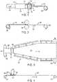
- the compound 10may be placed in an extruder, such as the ram extruder 12 shown in FIG. 1 .
- the ram extruder 12includes a barrel 13 and a piston 14 that is configured to slide within a chamber of the barrel 13 and form a seal against an inner cylindrical surface of the barrel 13.
- the compound 10is placed in the chamber of the extruder 12 between the distal end of the piston 14 and an extruder die 16 sealed to the output end 18 of the extruder 12.
- the ram extruder 12may also include heat elements 20 disposed about the output end 18 of the barrel 13 which are configured to uniformly heat the output end 18 of the extruder 12. In some methods, the output end 18 of the extruder is heated before the compounded PTFE resin 10 is loaded into the chamber.
- An embodiment of a ram extruder 12may include a Phillips Scientific Corporation vertical three inch hydraulic ram extruder.
- the piston 14is advanced towards the output end 18 of the extruder 12, as indicated by arrow 21, which increases the chamber pressure and forces the PTFE compound 10 to be extruded through an orifice 22 of the die 16 to form an extrudate 24.
- the extrudate 24may be in the form of a ribbon or tape that is then wound onto a take up spool 26 as indicated by the arrow adjacent the take up spool in FIG. 1 .
- the ram extrusion processrepresents a mechanical working of the compound 10 and introduces shear forces and pressure on the compound 10. This working of the compound results in a more cohesive material in the form of extrudate ribbon or tape 24.
- Processing conditionsmay be chosen to minimize the amount of lubricant that is evaporated from the PTFE extrudate ribbon 24.
- the PTFE compound 10may be extruded at a temperature that is above the glass transition temperature, and typically above about 90°F.
- the PTFE extrudate ribbon 24is generally fully densified, non-porous and typically has approximately 100% of its original amount of lubricant remaining upon extrusion from the die 16.
- the die 16may also be configured to produce an extrudate 24 having other configurations, such as a tubular configuration.
- the PTFE compound 10may be processed to form a preform billet before it is placed in the extruder 12.
- a de-ionizing air curtainoptionally may be used to reduce static electricity in the area of the extruder 12.
- the ram extruder 12has a barrel 13 with a chamber having an inside transverse diameter of about 2.54 cm (1 inch) to about 15.24 cm (6 inches) in diameter.
- Embodiments of the die 16may have orifices 22 configured to produce an extrudate ribbon or tape 24 having a width of about 2.54 cm (1 inch) to about 60.96 cm (24 inches) and a thickness of about 0.508 mm (0.020 inch) to about 1.016 mm (0.040 inch), specifically, about 0.635 mm (0.025 inch) to about 0.889 mm (0.035 inch).
- the wet PTFE extrudate ribbon 24may be calendered in a first direction or machine direction, as indicated by arrow 27, to reduce the thickness of the PTFE extrudate ribbon 24 into a PTFE layer 28 as shown in FIG. 2 .
- the width of the PTFE extrudate ribbon 24 and calendered PTFE layer 28changes little while the PTFE extrudate ribbon 24 is lengthened in the machine direction.
- the PTFE extrudate ribbon 24 and calendered PTFE layer 28may be (about 6 inches) to (about 10 inches) in width.
- the calendering processboth lengthens and reduces the thickness of the PTFE ribbon 24 to form PTFE layer 28 that is taken up by spool 32.
- the PTFE extrudate ribbon 24may be calendered between adjustable heated rollers 30 to mechanically compress and reduce the thickness of the PTFE ribbon 24.
- the calendering processalso encompasses a second mechanical working of the compound 10.
- Suitable equipment for the calendering processincludes a custom 30.48 cm (12 inch) vertical calender machine manufactured by IMC Corporation, Birmingham, Alabama.
- lubricant in the PTFE extrudate ribbon 24will evaporate from the ribbon 24 during the storage period. As such, it may be desirable in some instances to calender the PTFE extrudate ribbon 24 almost immediately after extrusion so as to better control the lubricant level in the PTFE extrudate ribbon 24.
- the PTFE ribbon 24will have a lubricant content of about 15% to about 25% immediately prior to calendering.
- the PTFE ribbon 24may be calendered down to produce a PTFE layer 28 of any suitable thickness.
- the reduction ratio of an embodiment of the calendering processwhich is a ratio of the thickness of the PTFE extrudate ribbon 24 to the thickness of the calendered PTFE layer 28, maybe from about 3:1 to about 75:1, and specifically from about 7.5:1 to about 15:1.
- calenderingmay reduce its thickness to about 0.0254 mm (0.001 inch) to about 0.152 mm (0.006 inch), specifically, from about 0.0508 mm (0.002 inch) to about 0.1016 mm (0.004 inch).
- the PTFE ribbon 24may be calendered to a PTFE layer 28 which has a thickness that is slightly greater than a final desired thickness, so that the final stretch of the PTFE ribbon 24 causes the final PTFE layer 28 to have its desired thickness.
- the calendering temperatures and processing parametersmay be chosen so that the calendered PTFE layer 28 still has a significant amount of residual lubricant after the calendering process.
- the adjustable rollers 30may be heated to a temperature from about 37.78 °C (100°F) to about 93.33 °C (200°F), and specifically from about 48.49 °C (120°F) to about 71.11 °C (160°F) during the calendering process.
- a residual amount of lubricantwill remain in the PTFE layer 28 which typically may be from about 10% to about 22% lubricant by weight remaining, specifically about 15% to about 20% lubricant by weight.
- PTFE layer 28then may be mechanically stretched transversely (also called the cross machine direction), in the longitudinal direction (also called the machine direction), in both of these directions or any other suitable direction or combination of directions, in order to thin the PTFE layer 28, generate a suitable microstructure and mechanically work the PTFE.
- a PTFE layermay be first stretched longitudinally then stretched transversely. Such a layer optionally may then be densified as discussed below. For the transverse stretching process shown in FIGS.
- a tentering machine 34may be used to mechanically stretch the calendered PTFE layer 28 into a stretched PTFE layer 36.
- a suitable tentering machine 34includes a 1.524 m (60 inch) wide by 8.534 (28 foot) long tenter having a T-6 10 horsepower drive unit, manufactured by Gessner Industries, Concord, North Carolina.
- process parameterssuch as temperature, stretch ratios and material lubricant content of PTFE layer 28 may be controlled before and during the stretching process of the PTFE layer.
- a stretching agent or lubricant 40optionally may be applied to the calendered PTFE layer 28 during the stretching process as shown in FIGS. 3 and 4 . Applying the stretching agent 40 to the PTFE layer 28 prior to or during the stretching process of the PTFE layer 28 may be used to control the lubricant content of the stretched PTFE layer 36.
- This techniquemay be used to impart particular characteristics to the stretched PTFE layer 36 such as thinness, low porosity and low or substantially no fluid permeability.
- This method embodimentalso allows for the stretched PTFE layer 36 to have a high degree of limpness and suppleness so to allow mechanical manipulation or strain of such a PTFE layer without significant recoil or spring back which may be particularly useful for some applications. If a high density, liquid-impermeable and gas-impermeable PTFE layer 28 having low or substantially no fluid permeability is desired, the PTFE layer 28 may be saturated throughout the thickness of the PTFE layer 28 with one or more stretching agents 40 during stretching.
- Stretching the PTFE layer 28may be carried out for some embodiments at a temperature of about 26.67 °C (80°F) to about 37.38 °C (100°F), specifically, about 29.44 °C (85°F) to about 35°C (95°F).
- the stretching agent 40may be the same lubricant used to form the PTFE compound 10 or it may be a different lubricant or combination of lubricants. In some embodiments, the stretching agent may be applied in sufficient quantities to the PTFE layer 28 to saturate the PTFE layer 28 during the stretching process.
- the stretching agentmaybe applied by a variety of methods to a surface, such as the upper surface 38, of the PTFE layer 28 during the stretching process. For example, the stretching agent 40 may be sprayed over the entire layer 28 or only on selected portions of the PTFE layer 28 by, e.g., a method such as by a spray mechanism 42 to the upper surface 38 of the PTFE layer 28.
- the stretching agent 40is applied to the PTFE layer 28 after the PTFE layer 28 unwinds from spool 32 and passes under the spray mechanism 42.
- the stretching agent 40may be applied uniformly over one or both sides of the PTFE layer 28, on only one side of the PTFE layer 28, or only on selected portions of the PTFE layer 28 at a temperature of typically about 21.11 °C (70°F) to about 57.22 °C (135°F), specifically, about 40.56 °C (105°F) to about 51.67 °C (125°F), and more specifically, about 43.33 °C (110°F) to about 48.89 °C (120°F).
- the PTFE layer 28may be stretched in one or more directions while fully saturated until the desired thickness is achieved. It should be noted that as the PTFE layer 28 is stretched, the capacity of the resulting stretched PTFE layer 36 to absorb stretching agent 40 increases. As such, if it is desirable to maintain a saturated status of the PTFE layer 28 and stretched PTFE layer 36, it may be necessary to add stretching agent multiple times or over a large area in order to maintain that saturated state of the PTFE layer 36 and the effect of lubricant temperature for a period of time.
- FIG. 4illustrates the stretching agent or lubricant 40 being applied to upper surface 38 of the PTFE layer 28 by spray mechanism 42 as the PTFE layer 28 is being stretched transversely.
- the pooled or puddled stretching agentmay be spread over the upper surface 38 of the PTFE layer 28 by a skimming member 44 that has a smooth contact edge 46 adjacent the upper surface 38 of the PTFE layer 28. While not shown, multiple skimming members may be used with some or all having a smooth contact edge or alternatively a grooved/patterned contact edge.
- the skimming member 44is disposed adjacent the spray mechanism 42 displaced from the spray mechanism in the machine direction of the PTFE layer 28 such that the stretching agent 40 applied by the spray mechanism 42 runs into the skimming member 44 and is spread by the motion of the stretching agent 40 and PTFE layer 28 relative to the skimming member 44.
- the skimming member 44may be in contact with the upper surface 38 of the PTFE layer 28 or also may be disposed slightly above the upper surface 38, depending on the desired configuration of the set up, the type of stretching agent being used as well as other factors.
- Embodiments of methods discussed hereinmay be useful to reduce a thickness of the PTFE layer 28 to a stretched PTFE layer 36 of any thickness down to about 0.00127 mm (0.00005 inch); typically from about 0.00127 mm (0.00005 inch) and 0.127 mm (0.005 inch).
- Typical transverse stretch ratiosmay be from about 3:1 to about 20:1.
- a calendered PTFE layer 28 having a width of about 7.62 cm (3 inches) to about 15.24 cm (6 inches)may be transversely stretched, as shown in FIGS. 3 and 4 , into a stretched PTFE layer 36 having a width of about 50.8 cm (20 inches) to about 152.4 cm (60 inches). This represents a stretch ratio of about 3:1 to about 12:1.
- a calendered PTFE layer 28 having a width of about 8.89 cm (3.5 inches) to about 11.43 cm (4.5 inches)may be transversely stretched, as shown in FIGS. 3 and 4 , into a stretched PTFE layer 36 having a width of about 50.8 cm (20 inches) to about 152.4 cm (60 inches). This represents a stretch ratio of about 7.8:1 to about 13:1.
- the thickness, fluid permeability, porosity and average pore size of the PTFE layers 36may be effected by the amount and temperature of stretching agent 40 applied to the layer 36 prior to or during stretching, the temperature of the layer, the stretching agent that is applied to the PTFE layer, or both, prior to stretching and the stretch rate.
- these parametersmay be optimized in order to produce a PTFE layer that is suited to a particular application. For example, if the PTFE layer 36 is used as a moisture barrier for clothing, the parameters may be adjusted to produce an average pore size of less than about 6 microns.
- the average pore sizeis adjusted to be greater than 6.0 microns.
- the pore sizemay be smaller, such as from about 0.01 micron to about 5.0 microns.
- embodiments of the stretched PTFE layer 36are fusible and deformable and easily may be fused with or secured to other PTFE layers having different properties.
- the stretched PTFE layer 36may be sintered to amorphously lock the microstructure of the PTFE layer 36. Sintering may be performed to combine the stretched PTFE layer 36 with other layers of PTFE to form multi-layer composite films, such as those used for endovascular grafts and the like discussed below.
- the stretched PTFE layeroptionally may be subjected to a second stretching process, as shown in FIGS. 3, 4 , 5 and 6 , wherein the stretched PTFE layer 36 is formed into a twice-stretched PTFE layer 46.
- a second stretching processas shown in FIGS. 3, 4 , 5 and 6 , wherein the stretched PTFE layer 36 is formed into a twice-stretched PTFE layer 46.
- a PTFE layer 28may be stretched three or more times. Some or all of the speeds, stretch ratios, temperatures, lubricant parameters and the like discussed herein may be the same but need not necessarily and typically will not be the same for any of these various stretching steps regardless of the order the stretching steps.
- This optional second stretching processsubjects the PTFE layer 36 to yet another mechanical working.
- the second stretching process shown in FIGS. 5 and 6is being carried out in the machine direction; however, the second stretching process may also be carried out in any other suitable direction, such as transversely.
- the twice-stretched PTFE layer 46is wound onto spool 48 after undergoing the second stretching process.
- Additional stretching agent 40optionally may be applied to a surface of the stretched PTFE layer 36 as the layer 36 is being stretched a second time. If higher porosity and fluid permeability are desired, the second stretch may be performed with the stretched layer 36 in a dry state without the addition of lubricant during the second stretch.
- the second stretching processwill generate a microstructure having significant nodes connected by fibrils.
- the second stretching processmay be carried out at a temperature of about 29.44 °C (85°F) to about 35 °C (95°F) for some embodiments.
- the stretch ratio for the second stretchmaybe up to about 20:1, specifically, about 6:1 to about 10:1.
- the rate of stretching in the two directionsmay have different or the same stretch rates.
- the rate of stretchingis typically in the range from about two percent to about 100 percent per second; specifically, from about four percent to about 20 percent per second, and more specifically about five percent to about ten percent per second.
- the rate of stretchingmay be in the range from about one percent to about 300 percent per second, specifically from about ten percent to about 100 percent per second, and more specifically about 15 percent to about 25 percent per second.
- Stretching in the different directionsmay be carried out at the same temperatures or at different temperatures.
- stretching in the machine directionis generally carried out at a temperature below about 300 °C (572°F), and for some embodiments, below about 115 °C (239°F).
- stretching in the transverse directionis typically carried out at a temperature above the glass transition temperature, and usually from about 26.67 °C (80°F) to about 37.78 °C (100°F).
- Stretching PTFE layers 28 at lower temperatureswill reduce stretching agent 40 evaporation and retain the stretching agent 40 in the PTFE layer 28 for a longer period of time during processing.
- Either the stretched PTFE layer 36 or the twice-stretched PTFE layer 46optionally may be calendered in order to further thin and densify the material.
- the twice-stretched PTFE layer 46is shown being calendered in FIGS. 7 and 8 .
- the twice-stretched PTFE layer 46is unwound from spool 48, passed through calender rollers 50 and 52, formed into a densified layer 54, then taken up on spool 54.
- the calender machinemay be the same machine or a different machine as that indicated in FIG. 2 and discussed above.
- This final calendering or densification of PTFE layer 46generally produces a highly densified PTFE layer 54 that has no discernable microstructure features, such as pores, and has low or substantially no fluid permeability.
- the methods of compressing and stretching PTFE layersmay both be used to control thinning of the PTFE layer and the microstructure that results from the thinning process.
- the densified PTFE layer 54may also lack the suppleness and limpness mechanical properties of the stretched PTFE layers 36 and 46 discussed above.
- the rollers 50 and 52may be adjusted to have any suitable separation to produce a PTFE layer 54 having a thickness of about 0.00127 mm (0.00005 inch) to about 0.127 mm (0.005 inch).
- the rollers 50 and 52may also be heated during the calendering process, with typical temperatures being from about 32.22 °C (90°F) to about 121.11 °C (250°F); specifically, from about 48.89 °C (120°F) to about 71.11 °C (160°F); more specifically, from about 54.44 °C (130°F) to about 65.56 °C (150°F).
- the following exampledescribes specific methods of manufacturing of the stretched PTFE layers 36.
- 1000 grams of resinare compounded with an isoparaffin based lubricant; specifically, ISOPAR ® M, in a mass ratio of lubricant-to-PTFE compound from about 15% to about 25%.
- Compounding of the PTFE resin and lubricantis carried out at a temperature below 10 °C (50°F), which is well below the glass transition temperature of the PTFE resin of between about 13.89 °C (57°F) to about 23.89 °C (75°F).
- the PTFE compound 10maybe formed into a billet and stored at a temperature of about 40.56 °C (105°F) to about 51.67 °C (125°F) for six or more hours to ensure that the lubricant substantially has penetrated and absorbed through the resin. Thereafter, the PTFE compound 10 is placed in an extruder 12, as shown in FIG. 1 . The PTFE compound 10 may then be paste extruded from the orifice 22 of the die 16 of the extruder 12 at a temperature above the resin glass transition temperature. In one embodiment, the paste is extruded at a temperature from about 26.67 °C (80°F) to 48.89 °C (120°F).
- a reduction ratioe.g., a ratio of a cross sectional area of the PTFE compound 10 before extrusion to the cross section area of the PTFE extrudate 24 after extrusion, may be from about 10:1 to about 400:1, and specifically may be from about 80:1 to about 120:1.
- the extruder 12maybe a horizontal extruder or a vertical extruder.
- the orifice 22 of the extrusion die 16determines the final cross sectional configuration of the extruded PTFE ribbon 24.
- the orifice 22 shape or configuration of the extrusion die 16may be tubular, square, rectangular or any other suitable profile. It may be desirable to preform the PTFE compound (resin and lubricant) into a billet.
- the PTFE extrudate ribbon 24is then calendered, as shown in FIG. 2 , at a temperature from about 37.78 °C (100°F) to about 71.11 °C (160°F) to reduce a thickness of the PTFE ribbon 24 and form a PTFE layer or film 28.
- the temperature at calenderingmay be controlled by controlling the temperature of the rollers 30 of the calender machine.
- the PTFE layermay be calendered down to a thickness from about 0.0254 mm (0.001 inch) to about 0.1524 mm (0.006 inch), and specifically, down to a thickness of about 0.0508 mm (0.002 inch) to about 0.0762 mm (0.003 inch).
- the calendered PTFE layer 28may have a lubricant content of about 10% by weight to about 20% by weight.
- one side or both sides of the calendered PTFE layer 28are sprayed with an isoparaffin-based stretching agent 40 at a prescribed temperature so that the PTFE film or layer 28 is flooded and fully saturated through the thickness of the PTFE layer 28.
- the saturated, calendered PTFE layermay then be stretched in a direction that is substantially orthogonal to the calendering direction by a tentering machine 34 to reduce a thickness of the PTFE layer 28 and form a stretched PTFE layer 36.
- the stretched PTFE layer 36may have a thickness of about 0.00127 mm (0.00005 inch) to about 0.127 mm (0.005 inch); specifically, the stretched PTFE layer 36 may have a thickness of about 0.00508 mm (0.0002 inch) to about 0.0508 mm (0.002 inch).
- the PTFE layer 28typically is tentered or stretched at an elevated temperature above the glass transition temperature, specifically, from about 26.67 °C (80°F) to about 37.78 °C (100°F), more specifically, about 29.44 °C (85°F) to about 35 °C (95°F).
- stretched PTFE layer 28wet tentering with the stretching agent 40 allows the PTFE layer 28 to be thinned without creating substantial porosity and fluid permeability in the stretched PTFE layer 36. While the stretched PTFE layer 36 will have a porosity, its porosity and pore size typically will not be large enough to be permeable to liquids, and often will be small enough to have substantially no fluid permeability. In addition, the stretched PTFE layer embodiment 36 does not have the conventional node and fibril microstructure but instead has a closed cell microstructure in which boundaries of adjacent nodes are directly connected with each other.
- the fluid-impermeable stretched PTFE film or layer 36typically may have a density from about 0.5g/cm3 to about 1.5g/cm3, but it may have a larger or smaller density for some embodiments.
- any of the PTFE layers produced by these methodsmay also be sintered at any point in the above processes in order to substantially fix the microstructure of the PTFE layer.
- a typical sintering processmay be to expose the PTFE layer to a temperature of about 350°C to about 380°C for several minutes; specifically, about 2 minutes to about 5 minutes.
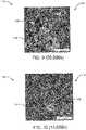
- PTFE layer 110has a generally closed cell microstructure 112 that is substantially free of the conventional node and fibril microstructure commonly seen in expanded PTFE layers.
- Embodiments of the PTFE film 110may have low fluid-permeability, or no or substantially no fluid-permeability.
- One or more of PTFE layer 110may be used as a barrier layer to prevent a fluid such as a liquid or gas from permeating or escaping therethrough.
- the microstructure of the stretched PTFE layer 110resembles a pocked-like structure that comprises interconnected high density regions 114 and pockets or pores 116 between some of the high density regions 114.
- the PTFE film 110may be considered to have a closed cell network structure with interconnected strands connecting high density regions 114 in which a high density region grain boundary is directly connected to a grain boundary of an adjacent high density region.
- PTFE layer 110Unlike conventional expanded PTFE ("ePTFE”) which typically has a substantial node and fibril microstructure that is discernable when viewed at a SEM magnification of 20,000, PTFE layer 110 lacks the distinct, parallel fibrils that interconnect adjacent nodes of ePTFE and has no discernable node and fibril microstructure when viewed at a SEM magnification of 20,000, as shown in FIG. 9 .
- the closed cell microstructure of the PTFE layer 110provides a layer having low or substantially no fluid permeability that may be used as "a barrier layer" to prevent liquid from passing from one side of the PTFE layer to the opposite side.
- PTFE film or layer 110is configured to have low or substantially no fluid permeability, PTFE layer 110 nonetheless has a porosity.
- the PTFE layer 110typically has an average porosity from about 20% to about 80%, and specifically from about 30% and about 70%. In one embodiment, a PTFE film 110 has a porosity of about 30% to about 40%. In another embodiment, a PTFE layer 110 has a porosity of about 60% to about 70%. Porosity as described in these figures is meant to indicate the volume of solid PTFE material as a percentage of the total volume of the PTFE film 110.
- An average pore size in the PTFE layer 110is may be less than about 20 microns, and specifically less than about 0.5 micron.
- a PTFE layer 110has an average pore size of from about 0.01 micron to about 0.5 micron. As can be appreciated, if tissue ingrowth is desired, the PTFE film 110 may have an average pore size of greater than about 6.0 microns. As described below, depending on the desired properties of the resultant PTFE layer 110, embodiments of methods may be modified so as to vary the average porosity and average pore size of the PTFE film 110 in a continuum from 10 microns to 50 microns down to substantially less than about 0.1 micron.
- PTFE layer 110may have a density from about 0.5 g/cm 3 to about 1.5 g/cm 3 , and specifically from about 0.6 g/cm 3 to about 1.5 g/cm 3 . While the density of the PTFE film 110 is typically less than a density for a fully densified PTFE layer (e.g., 2.1 g/cm 3 ), if desired, the density of the PTFE layer 110 may be densified to a higher density level so that the density of the PTFE layer 110 is comparable to a fully densified PTFE layer.
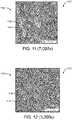
- FIGS. 9 to 13illustrate a PTFE film 110 having a closed microstructural network and that is substantially impermeable to liquid and gas; other embodiments of PTFE layers may be manufactured using the methods discussed herein to have other suitable permeability values and pore sizes.
- PTFE film 110may have an average thickness that is less than about 0.127 mm (0.005 inch), specifically from about 0.00127 mm (0.00005 inch) to about 0.127 mm (0.005 inch), and more specifically from about 0.00254 mm (0.0001 inch) to about 0.0508 mm (0.002 inch).
- PTFE layers and PTFE filmsmay be used in a variety of ways.
- the PTFE layer and PTFE film embodiments of the present inventionmay be used for prosthetic devices such as a vascular graft, breast implants and the like.
- Other applicationsinclude tubing, protective clothing, insulation, sports equipment, filters, membranes, fuel cells, ionic exchange barriers, gaskets as well as others.
- PTFE layer 110maybe combined with, bonded to, or otherwise coupled, affixed or attached, partially or completely, to at least one additional layer 118 to form a composite film 120.
- layer 118may be chosen to have properties that combine with the properties of layer 110 to give the desired properties in composite film 120.
- the additional layer 118may include a porous PTFE layer, a substantially non-porous PTFE layer, an air or liquid permeable PTFE layer, an air- or liquid-impermeable layer, an ePTFE layer, a non-expanded PTFE layer, a fluoropolymer layer, a non-fluoropolymer layer, or any combination thereof.
- layer 118is a porous, fluid permeable, expanded PTFE layer having a conventional node and fibril microstructure. If desired, one or more reinforcing layers (not shown) optionally may be coupled to the composite PTFE film 120.
- the reinforcing layermay be disposed between layers 110 or 118, or the reinforcing layer(s) may be coupled to an exposed surface of PTFE layer 110, PTFE layer 118, or both.
- PTFE layer 110 and layer 118may be combined, bonded to, or otherwise coupled, affixed or attached, partially or completely, to one another using any suitable method known in the art.
- an adhesivemay be used to selectively bond at least a portion of layers 110 and 118 to each other.
- heat fusion, pressure bonding, sintering, and the likemay be used to bond at least a portion of layers 110 and 118 to each other.
- FIGS. 15 and 16are transverse cross-sectional views of two composite tubular structures 130 and 140, respectively.
- Tubular structures 130 and 140may be a portion or section of an endovascular graft or the like.
- tubular structure 130includes an inner tubular body 132 that comprises an inner surface 134 and an outer surface 136.
- Tubular body 132may comprise one or more layers of fluid-permeable PTFE.
- Such a fluid-permeable layer of PTFEmay have a Gurley measurement of less than about 10 Gurley seconds.
- Tubular structure 130further comprises an outer tubular body 138 that comprises an inner surface 137 and an outer surface 139. Inner surface 137 of outer tubular body 138 is coupled to the outer surface 136 of the inner tubular body 132.
- Tubular body 138may comprise one or more PTFE layers having low fluid-permeability or substantially no fluid-permeability.
- inner surface 134 of the tubular body 132defines an inner lumen 135 of tubular structure 130 and the outer surface 139 of the tubular body 138 defines an outer surface 139 of the tubular structure 130.
- Tubular body 138may be combined, bonded to, or otherwise coupled, affixed or attached, partially or completely, to the tubular body 132 through any suitable method known in the art.
- an adhesivemay be used to selectively bond at least a portion of tubular body 138 and tubular body 132 to each other.
- heat fusion, pressure bonding, sintering, and the like, or any combination thereofmay be used to bond at least a portion of tubular body 138 and tubular body 132 to each other.
- tubular structure 140includes an inner tubular body 142 that comprises an inner surface 144 and an outer surface 146.
- Tubular body 142may comprise one or more layers of PTFE having low or substantially no fluid permeability.
- Tubular structure 140further comprises an outer tubular body 148 that comprises an inner surface 147 and an outer surface 149.
- Inner surface 147 of outer tubular body 148is coupled to the outer surface 146 of the inner tubular body 142.
- Outer tubular body 148may comprise one or more layers of fluid-permeable PTFE.
- Embodiments of fluid-permeable layers of PTFEmay have a Gurley measurement of less than about 10 Gurley seconds.
- inner surface 144 of the inner tubular body 142defines an inner lumen 145 of tubular structure 140 and the outer surface 149 of the outer tubular body 148 defines an outer surface 149 of the tubular structure 140.
- Tubular body 148may be combined, bonded to, or otherwise coupled, affixed or attached, partially or completely, to the tubular body 142 through any suitable method known in the art.
- an adhesivemay be used to selectively bond at least a portion of tubular body 148 and tubular body 132 to each other.
- heat fusion, pressure bonding, sintering, and the like, or any combination thereof,may be used to bond at least a portion of tubular body 148 and tubular body 142 to each other.
- Tubular structures 130 or 140may define an inner diameter ID which is the diameter of the inner surface, which may define the area of flow through tubular structure 130 or 140.
- An outer diameter ODwhich is the diameter of the outer surface 139 or 149 of the outer tubular layer 138 or 148.
- the inner diameter ID and outer diameter ODmay be any desired diameter.
- the inner diameter IDbut is typically from about 10 mm to about 40 mm and the outer diameter OD is typically from about 12 mm to about 42 mm.
- the tubular layersmay have any suitable thickness, however, fluid-impermeable PTFE layers 138 and 142 have a thickness from about 0.00127 mm (0.0005 inch) and about 0.254 mm (0.01 inch) thick, and specifically from about 0.00508 mm (0.0002 inch) to about 0.0254 mm (0.001 inch).
- fluid-permeable PTFE layers 132 or 148may also be any thickness desired, but typically have a thickness from about 0.00254 mm (0.0001 inch) and about 0.254 mm (0.01 inch), and specifically from about 0.00508 mm (0.0002 inch) to about 0.0254 mm (0.001 inch).
- the thicknesses and diameters of the tubular structures 130 or 140will vary depending on the use of the tubular structures.
- Tubular structures 130 or 140may be formed as tubes through conventional tubular extrusion processes. Typically, however, tubular structures 130 or 140 may be formed from PTFE layers 110 or 118, as shown in FIG. 14 , that are folded on a shape forming mandrel over each other so that ends of the layers are overlapped and bonded (not shown). As another alternative, PTFE layers 110 or 118 may be helically wound about the shape forming mandrel to form the tubular structure. Some exemplary methods of forming a tubular PTFE structure is described in commonly owned, copending U.S. Patent Application Serial Nos.
- the films and layers discussed hereinare not limited to a single porous PTFE layer 118 and a single PTFE layer or film 110 having low or substantially no fluid permeability.
- the composite films 120 and tubular structures 130 or 140may include a plurality of porous fluid permeable PTFE layers (having the same or different node and fibril size and orientation, porosity, pore size, and the like), one or more non-porous, densified PTFE layers, and/or one or more PTFE layers 110 having low or substantially no fluid permeability.
- PTFE layer 110 having low or substantially no fluid permeabilitymay be disposed between an inner and outer porous PTFE film or layer.
- the inner and outer porous PTFE layersmay have varying porosities or the same porosities.
- the PTFE layer 110may have a reduced thickness relative to the porous PTFE layers. In other embodiments, however, the PTFE layer 110 may have the same thickness or larger thickness than the porous PTFE layers.
- tubular structures 130 or 140may comprise inner and outer tubular bodies that both have low or substantially no fluid permeability.
- proximaldescribes the end of the graft that will be oriented towards the oncoming flow of bodily fluid, typically blood, when the device is deployed within a body passageway.
- distaltherefore describes the graft end opposite the proximal end.
- Graft 150has a proximal end 151 and a distal end 152 and includes a generally tubular structure or graft body section 153 comprised of one or more layers of fusible material, including such materials as PTFE and ePTFE.
- the inner surface of the tubular structuredefines an inner diameter and acts as a luminal surface for flow of fluids therethrough.
- the outer surface of the tubular structuredefines an abluminal surface that is adapted to be positioned adjacent the body lumen wall, within the weakened portion of the body lumen, or both. Note that although FIG. 17 shows an inflatable endovascular graft, the layers and films of the present invention may be used in non-inflatable endovascular grafts as well, in addition to other medical and non-medical applications.
- a proximal inflatable cuff 156may be disposed at or near a proximal end 151 of graft body section 153 and a distal inflatable cuff 157 may be disposed at or near a graft body section distal end 152.
- Graft body section 153forms a longitudinal lumen that is configured to confine a flow of fluid, such as blood, therethrough.
- Graft 150may be manufactured to have any desired length and internal and external diameter but typically ranges in length from about 5 cm to about 30 cm; specifically from about 10 cm to about 30 cm.
- a stent 159may be attached at the proximal end 151 and/or the distal end 152 of the graft 150.
- cuffs 156 and 157may assume a generally annular or toroidal shape with a generally semicircular longitudinal cross-section.
- Inflatable cuffs 156 and 157may be designed to generally, however, conform to the shape of the vessel within which it is deployed. When fully inflated, cuffs 156 and 157 may have an outside diameter ranging from about 10 mm to about 45 mm; specifically from about 16 mm to about 42 mm.
- At least one inflatable channel 158may be disposed between and in fluid communication with proximal inflatable cuff 156 and optional distal inflatable cuff 157.
- Inflatable channel 158 in the FIG. 17 examplehas a helical configuration and provides structural support to graft body section 153 when inflated to contain an inflation medium. Inflatable channel 158 further prevents kinking and twisting of the tubular structure or graft body section when it is deployed within angled or tortuous anatomies as well as during remodeling of body passageways, such as the aorta and iliac arteries, within which graft 150 may be deployed. Together with proximal and distal cuffs 156 and 157, inflatable channel 158 forms an inflatable network over the length of the body 153.
- At least one layer of the graftmay be a PTFE layer having low or substantially no fluid permeability such as PTFE layer or film 110.
- the PTFE layermay be one of the layers that forms the inflatable channels 158, or the PTFE layer may surround or be underneath the inflatable channel 158 and cuffs 156 and 157.
- Graft body 153may be formed of two or more layers or strips of PTFE that are selectively fused or otherwise adhered together as described herein, to form the inflatable cuffs 156 and 157 and inflatable channel 158 therebetween.
- a detailed description of some methods of manufacturing a multi-layered graftare described in co-pending and commonly owned U.S. Patent Application Serial Nos. 10/029,557 (which published as US 20030116260 A1 ), 10/029,584 , U.S. Patent Application Serial No. 10/168,053, filed June 14, 2002 and entitled "Inflatable Intraluminal Graft" to Murch , and U.S. Patent No. 6,776,604 to Chobotov et al.
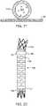
- FIGS. 18 to 21illustrate transverse cross sectional views of different embodiments of inflatable channel 158.
- Inflatable channel 158defines an inflatable space 162 that is created between an inner layer 164 and outer layer 166.
- an inflation medium 167may be delivered into the space 162 to inflate inflatable space 162.
- Inflation medium 167optionally may include a deliverable agent 168 as shown in FIGS. 18 to 21 , such as a therapeutic agent 168 that may be configured to be diffused in a controlled manner or otherwise transmitted through pores (not shown) in inner layer 164, outer layer 166 or both.
- a deliverable agent 168as shown in FIGS. 18 to 21 , such as a therapeutic agent 168 that may be configured to be diffused in a controlled manner or otherwise transmitted through pores (not shown) in inner layer 164, outer layer 166 or both.
- both layers 164 and 166may be configured to allow a significant amount of diffusion of deliverable agent 168, but with one of the two layers having a greater permeability to the deliverable agent 168 than the other layer. While inner layer 164 and layer 166 are shown as having only a single layer of material, it should be appreciated that each of layers 164 or 166 may include one or more layers to form a composite film of fluid-permeable PTFE, PTFE having low fluid permeability, PTFE having substantially no fluid permeability or any combination thereof.
- outer layer 166is permeable to fluids so as to allow the therapeutic agent 168, which may be a liquid, to diffuse over time in the direction of arrow 169 through outer layer 166.
- inner layer 164typically has a low or substantially no fluid permeability, and could therefore be considered a "barrier layer.” Because the inner "barrier" layer 164 has low or substantially no fluid permeability and outer layer 166 is fluid permeable, the therapeutic agent will preferentially diffuse from space 162 in the direction of arrow 169.
- porous fluid permeable outer PTFE layers and an inner layer 164 having low or substantially no fluid permeabilityprovides for improved release of a therapeutic agent through liquid permeable outer layer 166. Varying the porosity or pore size across at least a portion of outer layer 166 may provide even more localized delivery of the therapeutic agent 168 through outer layer 166.
- inner layer 164may be substantially fluid-permeable to allow the therapeutic agent 168 to selectively diffuse in the direction of arrow 169 through inner layer 164 and into the lumen of the tubular structure (e.g., lumen 135, 145 of FIGS. 15 and 16 ).
- outer layer 166typically has no or substantially no fluid-permeability and acts as a "barrier layer.” As such, the therapeutic agent will preferentially diffuse from space 162 in the direction of arrow 169.
- the use of porous fluid permeable PTFE layers and outer layer 166 having low or substantially no fluid permeabilityprovides for improved release of a therapeutic agent into the inner lumen through fluid permeable inner layer 164. Varying the permeability and/or porosity or pore size across at least a portion of inner layer 164 may provide even more localized delivery of the therapeutic agent 168 through layer 164.
- both the inner layer 164 and outer layer 166may comprise a "barrier" layer having low or substantially no fluid permeability.
- the inner and outer layers 164 and 166have low or substantially no fluid permeability.
- inflation material 167typically will not contain a therapeutic agent.
- the inflatable channelmay be a substantially tubular channel 170 that is fused or otherwise adhered to layer 164 that defines a portion of the graft. If delivery of a therapeutic agent is desired, tubular channel 170 will be liquid-permeable and will allow diffusion of the therapeutic agent 168 through pores in tubular channel 170.
- tubular channel 170may act as a barrier layer and may comprise at least one layer of PTFE having low or substantially no fluid permeability.
- the respective graft embodiments 150 and 180 showninclude an inflatable channel 158 has portions with a circumferential configuration as opposed to the helical configuration of the inflatable channel 158 shown in FIG. 17 .
- the circumferential configuration of portions of the inflatable channel 158may be particularly effective in providing the needed kink resistance for endovascular graft for effectively treating diseased body passageways such as a thoracic aortic aneurysm (TAA), abdominal aortic aneurysm (AAA), in which highly angled and tortuous anatomies are frequently found.
- TAAthoracic aortic aneurysm
- AAAabdominal aortic aneurysm
- Inflatable channel 158may be configured circumferentially as shown in FIGS. 22 and 23 .
- bifurcated endovascular graftsas shown in FIG. 23 , are also contemplated.
- the bifurcated endovascular graft 180may be utilized to repair a diseased lumen at or near a bifurcation within the vessel, such as, for example, in the case of an abdominal aortic aneurysm in which the aneurysm to be treated may extend into the anatomical bifurcation or even into one or both of the iliac arteries distal to the bifurcation.
- the various features of the graft embodiments previously discussedmay be used as necessary in the bifurcated graft 80 embodiment unless specifically mentioned otherwise.
- Graft 180comprises a first bifurcated portion 182, a second bifurcated portion 184 and main body portion 186.
- the size and angular orientation of the bifurcated portions 182 and 184may vary to accommodate graft delivery system requirements and various clinical demands. The size and angular orientation may vary even between portion 182 and 184. For instance, each bifurcated portion or leg is shown in FIG. 23 to optionally have a different length.
- First and second bifurcated portions 182 and 184are generally configured to have an outer inflated diameter that is compatible with the inner diameter of a patient's iliac arteries.
- First and second bifurcated portions 182 and 184may also be formed in a curved shape to better accommodate curved and even tortuous anatomies in some applications.
- main body portion 186 and first and second bifurcated portions 182 and 184form a continuous bifurcated lumen, similar to the inner lumens of FIG. 22 , which is configured to confine a flow of fluid therethrough.
- a complete description of some desirable sizes and spacing of inflatable channelsmay be found in commonly owned, copending U.S. Patent Application Serial No. 10/384,103 (which published as US 20040176836 A1), entitled “Kink-Resistant Endovascular Graft" and filed March 6, 2003 to Kari et al.
- the bifurcated graft 180may comprise a helical inflatable channel 158, similar to that of the graft embodiment shown in FIG. 17 (or other channel geometries to achieve desired results), or a combination of helical and circumferential channels.
- a complete description of some embodiments of endovascular grafts that have helical and cylindrical channel configurationsmay be found in co-pending and commonly owned U.S. Patent Application Serial No. 10/384,103 (which published as US 20040176836 A1 ).
- Other endovascular grafts that the liquid-impermeable PTFE film may be used withare described in U.S.
- Patents 6,395,019 to Chobotov , 6,132,457 to Chobotov , 6,331,191 to Chobotovand U.S. Patent Application Serial Nos. 10/327,711 (which published as US 20030125797 A1), entitled “Advanced Endovascular Graft” to Chobotov et al. and filed December 20, 2002 , 10/168,053 .
- the inflatable portions of the graft 180optionally may be configured to have varying levels of fluid permeability and/or porosity, either within or between particular cuffs, channels or cuff/channel segments, so as to provide for controlled drug delivery, programmed drug delivery or both, into the vessel wall or lumen of the graft via elution of the agent from pores in the layers.
- any desired portion of the graft 180may include PTFE layers having low or substantially no fluid permeability.
- Such a configurationwould be useful in applications in which the drug delivery rate and other properties of the graft or stent-graft (e.g. mechanical properties) may be selected for the particular clinical needs and indication that is contemplated for that device.
- the fluid permeability and/or porositymay be uniform within a particular cuff or channel but different between any given channel and/or cuffs.
- the variable porosity of the outer surface of the graftmay also be beneficial for promoting tissue in-growth into the graft. It may be possible to make portions of the graft that are in direct contact with the body lumen to have a higher porosity and/or larger pore size so as to promote tissue in-growth. In particular, tissue in-growth may be beneficial adjacent to the proximal and distal ends of the graft.
Landscapes
- Health & Medical Sciences (AREA)
- Engineering & Computer Science (AREA)
- Mechanical Engineering (AREA)
- Chemical & Material Sciences (AREA)
- Veterinary Medicine (AREA)
- Oral & Maxillofacial Surgery (AREA)
- Transplantation (AREA)
- Life Sciences & Earth Sciences (AREA)
- Animal Behavior & Ethology (AREA)
- General Health & Medical Sciences (AREA)
- Public Health (AREA)
- Medicinal Chemistry (AREA)
- Epidemiology (AREA)
- Dermatology (AREA)
- Chemical Kinetics & Catalysis (AREA)
- Pulmonology (AREA)
- Gastroenterology & Hepatology (AREA)
- Cardiology (AREA)
- Biomedical Technology (AREA)
- Heart & Thoracic Surgery (AREA)
- Vascular Medicine (AREA)
- Dispersion Chemistry (AREA)
- Laminated Bodies (AREA)
- Manufacture Of Porous Articles, And Recovery And Treatment Of Waste Products (AREA)
- Shaping By String And By Release Of Stress In Plastics And The Like (AREA)
- Prostheses (AREA)
- Polymers & Plastics (AREA)
- Organic Chemistry (AREA)
- Media Introduction/Drainage Providing Device (AREA)
- Materials For Medical Uses (AREA)
Description
- Polytetrafluoroethylene (PTFE) layers have been used for the manufacture of various types of intracorporeal devices, such as vascular grafts. Such vascular grafts may be used to replace, reinforce, or bypass a diseased or injured body lumen. One conventional method of manufacturing "expanded" PTFE layers is described in
U.S. Patent No. 3,953,566 by Gore . In the methods described therein, a PTFE paste is formed by combining a PTFE resin and a lubricant. The PTFE paste may be extruded. After the lubricant is removed from the extruded paste, the PTFE article is stretched to create a porous, high strength PTFE article. The expanded PTFE layer is characterized by a porous, open microstructure that has nodes interconnected by fibrils. - Such an expansion process increases the volume of the PTFE layer by increasing the porosity, decreasing the density and increasing the internodal distance between adjacent nodes in the microstructure while not significantly affecting the thickness of the PTFE layer. As such, the conventional methods expand the PTFE layer and impart a porosity and permeability while only providing a negligible reduction in a thickness of the PTFE layer. In situations where a thin PTFE layer, and specifically, a thin PTFE layer having a low fluid permeability is needed, conventional PTFE layers are largely unsatisfactory due to the porosity and highly permeable nature of the expanded PTFE layer.
- Therefore, what has been needed is improved PTFE layers and improved methods for manufacturing the PTFE layers. In particular, it would be desirable to have thin PTFE layers that have a controllable permeability to fluids (gases, liquids or both). It may also be desirable to have such thin PTFE layers that have a high degree of limpness and suppleness to allow mechanical manipulation or strain of such a PTFE layer without significant recoil or spring back.
- In
WO 95/05132 A1 US 2003/074016 A1 discloses a balloon catheter having the strength and maximum inflated diameter characteristics of an angioplasty balloon and having the recovery characteristics during deflation of an elastic embolectomy balloon. This patent application does not disclose either the provision of a non-fluid-permeable PTFE layer.US 2003/199992 A1 relates to a soft-tissue prosthesis which is formed from a tubular textile substrate and a liner. The liner is affixed to the intraluminal surface of the tubular textile portion of the soft-tissue prosthesis to form a fluid-tight barrier on the intraluminal surface of the prosthesis. This patent application does, however, not disclose the provision of a non-fluid-permeable PTFE layer.- The invention provides an endovascular graft as claimed in claim 1. Further embodiments of the endovascular graft are described in claims 2-9.
- The features of these embodiments will become more apparent from the following detailed description when taken in conjunction with the accompanying exemplary drawings.
FIG. 1 illustrates a ram extruder extruding a PTFE ribbon that is being taken up on a spool.FIG. 2 illustrates a calendering process of the PTFE ribbon ofFIG. 1 .FIGS. 3 and 4 illustrate a tentering process with stretching agent being applied to a PTFE layer during the stretching process.FIGS. 5 and 6 illustrate a machine direction stretching process of the stretched PTFE layer ofFIGS. 3 and 4 .FIGS. 7 and 8 illustrate a final calendering or densification process performed on a stretched PTFE layer.FIG. 9 is a scanning electron microscope (SEM) image of a PTFE layer at a magnification of 20,000.FIG. 10 is a SEM image of the PTFE layer ofFIG. 9 at a magnification of 14,000.FIG. 11 is a SEM image of the PTFE layer ofFIG. 9 at a magnification of 7,000.FIG. 12 is a SEM image of the PTFE layer ofFIG. 9 at a magnification of 3,000.FIG. 13 is a SEM image of the PTFE layer ofFIG. 9 at a magnification of 500.FIG. 14 schematically illustrates a composite PTFE film that comprises a PTFE layer having low or substantially no fluid permeability and a porous PTFE layer.FIG. 15 schematically illustrates a simplified tubular structure that comprises an outer layer having low or substantially no fluid permeability and a fluid-permeable inner layer.FIG. 16 schematically illustrates a simplified tubular structure that comprises a layer having low or substantially no fluid permeability and a fluid-permeable outer layer.FIG. 17 illustrates an embodiment of an endovascular graft having a network of inflatable conduits.FIGS. 18 to 20 are transverse cross sectional views of an inflatable conduit of the graft ofFIG. 17 .FIG 21 is a transverse cross sectional view of an embodiment of a tubular inflatable conduit.FIG. 22 is an elevational view that illustrates another embodiment of an inflatable endovascular graft.FIG. 23 illustrates an embodiment of an inflatable bifurcated endovascular graft.- Embodiments of the present invention relate generally to thin PTFE layers, PTFE films, and/or composite films having two or more PTFE layers applied in an endovascular graft.
- Some particular embodiments are directed to thin PTFE layers having low or substantially no fluid permeability with a microstructure that does not include significant fibril and nodal structure as is common with expanded PTFE layers. It may also be desirable for some embodiments of such thin PTFE layers that have a high degree of limpness and suppleness so to allow mechanical manipulation or strain of such a PTFE layer without significant recoil or spring back. Such PTFE layers may be manufactured and used for construction of endovascular grafts or other medical devices. For some applications, embodiments of PTFE films may include one or more discrete layers of PTFE that are secured together to form a composite film. As used herein, the term "composite film" generally refers to a sheet of two or more PTFE layers that have surfaces in contact with each other, and in some embodiments, may be secured to each other such that the PTFE layers are not easily separated. The individual PTFE layers used in some of the PTFE composite film embodiments herein may have the thinness and low fluid permeability characteristics discussed above in combination with other layers having the same or different properties Some PTFE layer embodiments have a low fluid permeability while other PTFE layer embodiments have no or substantially no fluid permeability. A PTFE layer having a low fluid permeability may, for some embodiments, be distinguished from the permeability of a standard layer of expanded PTFE by comparing fluid permeability based on Gurley test results in the form of a Gurley Number or "Gurley Seconds". The Gurley Seconds is determined by measuring the time necessary for a given volume of air, typically, 25 cc, 100 cc or 300 cc, to flow through a standard 1 square inch of material or film under a standard pressure, such as 12.4 cm column of water. Such testing maybe carried out with a Gurley Densometer, made by Gurley Precision Instruments, Troy, New York. A standard porous fluid permeable layer of expanded PTFE may have a Gurley Number of less than about 15 seconds, specifically, less than about 10 seconds, where the volume of air used is about 100 cc. In contrast, embodiments of layers of PTFE discussed herein having low fluid permeability may have a Gurley Number of greater than about 1500 seconds where 100 cc of air is used in the test. An embodiment of a PTFE layer discussed herein having no or substantially no fluid permeability may have a Gurley Number of greater than about 12 hours, or up to a Gurley Number that is essentially infinite, or too high to measure, indicating no measurable fluid permeability. Some PTFE layer embodiments having substantially no fluid permeability may have a Gurley Number at 100 cc of air of greater than about 1x10⁶ seconds. Stretched PTFE layers processed by embodiments of methods discussed herein having no discernable node or fibril microstructure may initially have substantially no fluid permeability. However, such PTFE layer embodiments may subsequently be stretched during a manufacturing process, such as the manufacture of an inflatable endovascular graft, during which process the PTFE layer may become more fluid permeable and achieve a level of low permeability as discussed above.
FIGS. 1-8 illustrate processing of PTFE material to form a thin, stretched PTFE layer having low or substantially no fluid permeability for particular fluids. As such, embodiments of the stretched PTFE layers are not "expanded" in the conventional sense as taught by Gore in, e.g.,U.S. Patent No. 3,953,566 . For example, the stretched PTFE layers may be substantially thinned during stretching whereas prior art "expansion" processes typically leave the thickness of the expanded material somewhat unchanged but generate distinct nodal and fibril microstructure along with increased porosity and permeability in order to accommodate the expansion of the layer in plane of the layer.- Referring to
FIG. 1 , a fine PTFE resin powder is compounded with an extrusion agent such as a liquid lubricant to form aPTFE compound 10. A variety of different PTFE resins may be used such as the lower extrusion ratio, higher molecular weight fine powder coagulated dispersion resins (available from 3M Corporation, Ausimont Corporation, Daikin Corporation, DuPont and ICI Corporation) The PTFE molecules used in these resins typically have an average molecular weight of from about 20 million to about 50 million or more. Optionally, an additive, such as powdered or liquid color pigment or other resin additive may be added to the PTFE resin and lubricant to change the properties of the final PTFE layer. For example, a fluorinated copolymer may be added (such as perfluoropropylvinylether-modified PTFE) to improve the bondability of the PTFE layer. Additive is typically provided in a mass amount that is less than 2% of the mass of the PTFE resin, but it may be provided in any amount that produces a desired result. Additive may be combined with the PTFE resin before the lubricant is added so as to ensure homogenous mixing of the additive throughout the PTFE resin. - A variety of different types of extrusion and stretching agents, or lubricants, may be compounded with the PTFE powder resin. Some examples of lubricants that may be mixed with the PTFE resin include, but are not limited to, isoparaffin lubricants such as ISOPAR® H, ISOPAR® K and ISOPAR® M all of which are manufactured by ExxonMobil Corporation. Additional lubricants include mineral spirits, naphtha, MEK, toluene, alcohols such as isopropyl alcohol, and any other chemical that is capable of saturating the PTFE resin. In addition, two or more lubricants may be blended together for some lubricant embodiments. The amount of lubricant added to the PTFE resin may vary depending on the type of lubricant used as well as the desired properties of a final PTFE layer. Typically, however, the percent mass of lubricant for some compound embodiments may vary from about 15% to about 25% of the compound mass, specifically, from about 17% to about 22% of the compound mass, and more specifically from about 18% to about 20% of the compound mass.
- The PTFE resin and lubricant may be mixed until a substantially
homogenous PTFE compound 10 is formed. Compounding of the PTFE resin and lubricant is typically carried out at a temperature below the glass transition temperature of the PTFE resin which is typically from about 12.78 °C (55°F) to about 24.44 °C (76°F). Compounding of the PTFE resin may be carried out at a temperature below about 10 °C (50°F), and specifically, at a temperature of from about 4.44 °C (40°F) to about 10 °C (50°F), so as to reduce shearing of the fine PTFE particles. Once mixed, the PTFE compound may be stored at a temperature of above approximately 37.78 °C (100°F), and typically from about 43.33 °C (110°F) to about 48.89 °C (120°F) for a time period that ensures that the lubricant has absorbed through the PTFE resin particles. The storage time period typically may be greater than about six hours, and may vary depending on the resin and lubricant used. - Once the compounded PTFE resin and
lubricant 10 have been suitably prepared, thecompound 10 may be placed in an extruder, such as theram extruder 12 shown inFIG. 1 . Theram extruder 12 includes abarrel 13 and apiston 14 that is configured to slide within a chamber of thebarrel 13 and form a seal against an inner cylindrical surface of thebarrel 13. Thecompound 10 is placed in the chamber of theextruder 12 between the distal end of thepiston 14 and an extruder die 16 sealed to theoutput end 18 of theextruder 12. Theram extruder 12 may also includeheat elements 20 disposed about theoutput end 18 of thebarrel 13 which are configured to uniformly heat theoutput end 18 of theextruder 12. In some methods, theoutput end 18 of the extruder is heated before the compoundedPTFE resin 10 is loaded into the chamber. An embodiment of aram extruder 12 may include a Phillips Scientific Corporation vertical three inch hydraulic ram extruder. - Once the PTFE resin compound is loaded, the
piston 14 is advanced towards theoutput end 18 of theextruder 12, as indicated byarrow 21, which increases the chamber pressure and forces thePTFE compound 10 to be extruded through anorifice 22 of the die 16 to form anextrudate 24. Theextrudate 24 may be in the form of a ribbon or tape that is then wound onto a take upspool 26 as indicated by the arrow adjacent the take up spool inFIG. 1 . The ram extrusion process represents a mechanical working of thecompound 10 and introduces shear forces and pressure on thecompound 10. This working of the compound results in a more cohesive material in the form of extrudate ribbon ortape 24. - Processing conditions may be chosen to minimize the amount of lubricant that is evaporated from the
PTFE extrudate ribbon 24. For example, thePTFE compound 10 may be extruded at a temperature that is above the glass transition temperature, and typically above about 90°F. ThePTFE extrudate ribbon 24 is generally fully densified, non-porous and typically has approximately 100% of its original amount of lubricant remaining upon extrusion from thedie 16. The die 16 may also be configured to produce anextrudate 24 having other configurations, such as a tubular configuration. Also, for some methods, thePTFE compound 10 may be processed to form a preform billet before it is placed in theextruder 12. In addition, a de-ionizing air curtain optionally may be used to reduce static electricity in the area of theextruder 12. In one example, theram extruder 12 has abarrel 13 with a chamber having an inside transverse diameter of about 2.54 cm (1 inch) to about 15.24 cm (6 inches) in diameter. Embodiments of the die 16 may haveorifices 22 configured to produce an extrudate ribbon ortape 24 having a width of about 2.54 cm (1 inch) to about 60.96 cm (24 inches) and a thickness of about 0.508 mm (0.020 inch) to about 1.016 mm (0.040 inch), specifically, about 0.635 mm (0.025 inch) to about 0.889 mm (0.035 inch). - After extrusion, the wet
PTFE extrudate ribbon 24 may be calendered in a first direction or machine direction, as indicated byarrow 27, to reduce the thickness of thePTFE extrudate ribbon 24 into aPTFE layer 28 as shown inFIG. 2 . During the calendering process, the width of thePTFE extrudate ribbon 24 and calenderedPTFE layer 28 changes little while thePTFE extrudate ribbon 24 is lengthened in the machine direction. In one embodiment, thePTFE extrudate ribbon 24 and calenderedPTFE layer 28 may be (about 6 inches) to (about 10 inches) in width. The calendering process both lengthens and reduces the thickness of thePTFE ribbon 24 to formPTFE layer 28 that is taken up byspool 32. During calendering, thePTFE extrudate ribbon 24 may be calendered between adjustableheated rollers 30 to mechanically compress and reduce the thickness of thePTFE ribbon 24. As such, the calendering process also encompasses a second mechanical working of thecompound 10. Suitable equipment for the calendering process includes a custom 30.48 cm (12 inch) vertical calender machine manufactured by IMC Corporation, Birmingham, Alabama. - While it may be possible to store the
PTFE extrudate ribbon 24 for an extended period of time after extrusion, lubricant in thePTFE extrudate ribbon 24 will evaporate from theribbon 24 during the storage period. As such, it may be desirable in some instances to calender thePTFE extrudate ribbon 24 almost immediately after extrusion so as to better control the lubricant level in thePTFE extrudate ribbon 24. For some embodiments, thePTFE ribbon 24 will have a lubricant content of about 15% to about 25% immediately prior to calendering. - Depending on the calendering speed and roller positioning, the
PTFE ribbon 24 may be calendered down to produce aPTFE layer 28 of any suitable thickness. The reduction ratio of an embodiment of the calendering process, which is a ratio of the thickness of thePTFE extrudate ribbon 24 to the thickness of the calenderedPTFE layer 28, maybe from about 3:1 to about 75:1, and specifically from about 7.5:1 to about 15:1. In one particular embodiment, for aPTFE extrudate ribbon 24 having a thickness of about 0.762 mm (0.030 inch), calendering may reduce its thickness to about 0.0254 mm (0.001 inch) to about 0.152 mm (0.006 inch), specifically, from about 0.0508 mm (0.002 inch) to about 0.1016 mm (0.004 inch). In some instances, thePTFE ribbon 24 may be calendered to aPTFE layer 28 which has a thickness that is slightly greater than a final desired thickness, so that the final stretch of thePTFE ribbon 24 causes thefinal PTFE layer 28 to have its desired thickness. - The calendering temperatures and processing parameters may be chosen so that the calendered
PTFE layer 28 still has a significant amount of residual lubricant after the calendering process. For this embodiment, theadjustable rollers 30 may be heated to a temperature from about 37.78 °C (100°F) to about 93.33 °C (200°F), and specifically from about 48.49 °C (120°F) to about 71.11 °C (160°F) during the calendering process. After calendering, a residual amount of lubricant will remain in thePTFE layer 28 which typically may be from about 10% to about 22% lubricant by weight remaining, specifically about 15% to about 20% lubricant by weight. - Once the
PTFE ribbon 24 has been calendered to producePTFE layer 28,PTFE layer 28 then may be mechanically stretched transversely (also called the cross machine direction), in the longitudinal direction (also called the machine direction), in both of these directions or any other suitable direction or combination of directions, in order to thin thePTFE layer 28, generate a suitable microstructure and mechanically work the PTFE. It should be noted that although this specification describes a process whereby a PTFE layer is stretched transversely, then stretched longitudinally and then densified, the order these steps are performed in may be changed. For example, a PTFE layer may be first stretched longitudinally then stretched transversely. Such a layer optionally may then be densified as discussed below. For the transverse stretching process shown inFIGS. 3 and 4 , atentering machine 34 may be used to mechanically stretch the calenderedPTFE layer 28 into a stretchedPTFE layer 36. One embodiment of asuitable tentering machine 34 includes a 1.524 m (60 inch) wide by 8.534 (28 foot) long tenter having a T-6 10 horsepower drive unit, manufactured by Gessner Industries, Concord, North Carolina. - For some embodiments, in order to produce the desired combination of any of thickness, porosity, fluid permeability as well as mechanical properties, process parameters such as temperature, stretch ratios and material lubricant content of
PTFE layer 28 may be controlled before and during the stretching process of the PTFE layer. As such, for some embodiments, a stretching agent orlubricant 40 optionally may be applied to the calenderedPTFE layer 28 during the stretching process as shown inFIGS. 3 and 4 . Applying the stretchingagent 40 to thePTFE layer 28 prior to or during the stretching process of thePTFE layer 28 may be used to control the lubricant content of the stretchedPTFE layer 36. This technique may be used to impart particular characteristics to the stretchedPTFE layer 36 such as thinness, low porosity and low or substantially no fluid permeability. This method embodiment also allows for the stretchedPTFE layer 36 to have a high degree of limpness and suppleness so to allow mechanical manipulation or strain of such a PTFE layer without significant recoil or spring back which may be particularly useful for some applications. If a high density, liquid-impermeable and gas-impermeable PTFE layer 28 having low or substantially no fluid permeability is desired, thePTFE layer 28 may be saturated throughout the thickness of thePTFE layer 28 with one or more stretchingagents 40 during stretching. If a moreporous PTFE layer 28 is desired, a lesser amount of stretchingagent 40 will be applied onto thePTFE layer 28. Stretching thePTFE layer 28 may be carried out for some embodiments at a temperature of about 26.67 °C (80°F) to about 37.38 °C (100°F), specifically, about 29.44 °C (85°F) to about 35°C (95°F). - The stretching
agent 40 may be the same lubricant used to form thePTFE compound 10 or it may be a different lubricant or combination of lubricants. In some embodiments, the stretching agent may be applied in sufficient quantities to thePTFE layer 28 to saturate thePTFE layer 28 during the stretching process. The stretching agent maybe applied by a variety of methods to a surface, such as theupper surface 38, of thePTFE layer 28 during the stretching process. For example, the stretchingagent 40 may be sprayed over theentire layer 28 or only on selected portions of thePTFE layer 28 by, e.g., a method such as by aspray mechanism 42 to theupper surface 38 of thePTFE layer 28. In such an embodiment, the stretchingagent 40 is applied to thePTFE layer 28 after thePTFE layer 28 unwinds fromspool 32 and passes under thespray mechanism 42. The stretchingagent 40 may be applied uniformly over one or both sides of thePTFE layer 28, on only one side of thePTFE layer 28, or only on selected portions of thePTFE layer 28 at a temperature of typically about 21.11 °C (70°F) to about 57.22 °C (135°F), specifically, about 40.56 °C (105°F) to about 51.67 °C (125°F), and more specifically, about 43.33 °C (110°F) to about 48.89 °C (120°F). - If a PTFE layer having low or substantially no fluid permeability is desired, the
PTFE layer 28 may be stretched in one or more directions while fully saturated until the desired thickness is achieved. It should be noted that as thePTFE layer 28 is stretched, the capacity of the resulting stretchedPTFE layer 36 to absorb stretchingagent 40 increases. As such, if it is desirable to maintain a saturated status of thePTFE layer 28 and stretchedPTFE layer 36, it may be necessary to add stretching agent multiple times or over a large area in order to maintain that saturated state of thePTFE layer 36 and the effect of lubricant temperature for a period of time. FIG. 4 illustrates the stretching agent orlubricant 40 being applied toupper surface 38 of thePTFE layer 28 byspray mechanism 42 as thePTFE layer 28 is being stretched transversely. For saturated stretching embodiments, it may be necessary to apply sufficient stretching agent so as to pool or puddle the stretching agent on theupper surface 38 of thePTFE layer 28. The pooled or puddled stretching agent may be spread over theupper surface 38 of thePTFE layer 28 by a skimmingmember 44 that has asmooth contact edge 46 adjacent theupper surface 38 of thePTFE layer 28. While not shown, multiple skimming members may be used with some or all having a smooth contact edge or alternatively a grooved/patterned contact edge. The skimmingmember 44 is disposed adjacent thespray mechanism 42 displaced from the spray mechanism in the machine direction of thePTFE layer 28 such that the stretchingagent 40 applied by thespray mechanism 42 runs into the skimmingmember 44 and is spread by the motion of the stretchingagent 40 andPTFE layer 28 relative to the skimmingmember 44. The skimmingmember 44 may be in contact with theupper surface 38 of thePTFE layer 28 or also may be disposed slightly above theupper surface 38, depending on the desired configuration of the set up, the type of stretching agent being used as well as other factors.- Embodiments of methods discussed herein may be useful to reduce a thickness of the
PTFE layer 28 to a stretchedPTFE layer 36 of any thickness down to about 0.00127 mm (0.00005 inch); typically from about 0.00127 mm (0.00005 inch) and 0.127 mm (0.005 inch). Typical transverse stretch ratios may be from about 3:1 to about 20:1. In one embodiment, a calenderedPTFE layer 28 having a width of about 7.62 cm (3 inches) to about 15.24 cm (6 inches), may be transversely stretched, as shown inFIGS. 3 and 4 , into a stretchedPTFE layer 36 having a width of about 50.8 cm (20 inches) to about 152.4 cm (60 inches). This represents a stretch ratio of about 3:1 to about 12:1. In another embodiment, a calenderedPTFE layer 28 having a width of about 8.89 cm (3.5 inches) to about 11.43 cm (4.5 inches) may be transversely stretched, as shown inFIGS. 3 and 4 , into a stretchedPTFE layer 36 having a width of about 50.8 cm (20 inches) to about 152.4 cm (60 inches). This represents a stretch ratio of about 7.8:1 to about 13:1. - As discussed above, the thickness, fluid permeability, porosity and average pore size of the PTFE layers 36 may be effected by the amount and temperature of stretching
agent 40 applied to thelayer 36 prior to or during stretching, the temperature of the layer, the stretching agent that is applied to the PTFE layer, or both, prior to stretching and the stretch rate. By adjusting these parameters, these characteristics may be optimized in order to produce a PTFE layer that is suited to a particular application. For example, if thePTFE layer 36 is used as a moisture barrier for clothing, the parameters may be adjusted to produce an average pore size of less than about 6 microns. Alternatively, if thePTFE layer 36 is used in an endovascular graft that benefits from tissue in-growth, the average pore size is adjusted to be greater than 6.0 microns. In other embodiments, where thePTFE layer 36 is a barrier layer for use in an endovascular graft, the pore size may be smaller, such as from about 0.01 micron to about 5.0 microns. In addition, embodiments of the stretchedPTFE layer 36 are fusible and deformable and easily may be fused with or secured to other PTFE layers having different properties. At any point after thePTFE layer 28 is stretched, the stretchedPTFE layer 36 may be sintered to amorphously lock the microstructure of thePTFE layer 36. Sintering may be performed to combine the stretchedPTFE layer 36 with other layers of PTFE to form multi-layer composite films, such as those used for endovascular grafts and the like discussed below. - The stretched PTFE layer optionally may be subjected to a second stretching process, as shown in
FIGS. 3, 4 ,5 and 6 , wherein the stretchedPTFE layer 36 is formed into a twice-stretchedPTFE layer 46. Once again, as discussed above, it is important to note that although the method embodiments discussed herein are directed to a first transverse stretch and subsequently to a longitudinal or machine direction stretch, the order of the stretch directions may be reversed and other combinations of stretch directions and numbers are also contemplated. For example,PTFE layer 28 may be stretched twice in the machine or longitudinal direction without any transverse stretching.PTFE layer 28 may be stretched first in a longitudinal or machine direction and then in a transverse direction. In addition, aPTFE layer 28 may be stretched three or more times. Some or all of the speeds, stretch ratios, temperatures, lubricant parameters and the like discussed herein may be the same but need not necessarily and typically will not be the same for any of these various stretching steps regardless of the order the stretching steps. - This optional second stretching process subjects the
PTFE layer 36 to yet another mechanical working. The second stretching process shown inFIGS. 5 and 6 is being carried out in the machine direction; however, the second stretching process may also be carried out in any other suitable direction, such as transversely. The twice-stretchedPTFE layer 46 is wound ontospool 48 after undergoing the second stretching process.Additional stretching agent 40 optionally may be applied to a surface of the stretchedPTFE layer 36 as thelayer 36 is being stretched a second time. If higher porosity and fluid permeability are desired, the second stretch may be performed with the stretchedlayer 36 in a dry state without the addition of lubricant during the second stretch. If the stretchedPTFE layer 36 has residual lubricant without additional lubricant added, the second stretching process will generate a microstructure having significant nodes connected by fibrils. The second stretching process may be carried out at a temperature of about 29.44 °C (85°F) to about 35 °C (95°F) for some embodiments. The stretch ratio for the second stretch maybe up to about 20:1, specifically, about 6:1 to about 10:1. - If the
PTFE layer 28 is stretched in two or more directions, the rate of stretching in the two directions; e.g., the machine direction and the off-axis or transverse direction, may have different or the same stretch rates. For example, when thePTFE layer 28 is being stretched in the machine direction (e.g., first direction), the rate of stretching is typically in the range from about two percent to about 100 percent per second; specifically, from about four percent to about 20 percent per second, and more specifically about five percent to about ten percent per second. In contrast, when stretching in the cross machine or transverse direction, the rate of stretching may be in the range from about one percent to about 300 percent per second, specifically from about ten percent to about 100 percent per second, and more specifically about 15 percent to about 25 percent per second. - Stretching in the different directions may be carried out at the same temperatures or at different temperatures. For example, stretching in the machine direction is generally carried out at a temperature below about 300 °C (572°F), and for some embodiments, below about 115 °C (239°F). In contrast, stretching in the transverse direction is typically carried out at a temperature above the glass transition temperature, and usually from about 26.67 °C (80°F) to about 37.78 °C (100°F). Stretching PTFE layers 28 at lower temperatures will reduce stretching
agent 40 evaporation and retain the stretchingagent 40 in thePTFE layer 28 for a longer period of time during processing. - Either the stretched
PTFE layer 36 or the twice-stretchedPTFE layer 46 optionally may be calendered in order to further thin and densify the material. The twice-stretchedPTFE layer 46 is shown being calendered inFIGS. 7 and 8 . In this example, the twice-stretchedPTFE layer 46 is unwound fromspool 48, passed throughcalender rollers layer 54, then taken up onspool 54. The calender machine may be the same machine or a different machine as that indicated inFIG. 2 and discussed above. This final calendering or densification ofPTFE layer 46 generally produces a highly densifiedPTFE layer 54 that has no discernable microstructure features, such as pores, and has low or substantially no fluid permeability. The methods of compressing and stretching PTFE layers may both be used to control thinning of the PTFE layer and the microstructure that results from the thinning process. The densifiedPTFE layer 54 may also lack the suppleness and limpness mechanical properties of the stretched PTFE layers 36 and 46 discussed above. Therollers PTFE layer 54 having a thickness of about 0.00127 mm (0.00005 inch) to about 0.127 mm (0.005 inch). Therollers - The following example describes specific methods of manufacturing of the stretched PTFE layers 36. In this embodiment, 1000 grams of resin are compounded with an isoparaffin based lubricant; specifically, ISOPAR® M, in a mass ratio of lubricant-to-PTFE compound from about 15% to about 25%. Compounding of the PTFE resin and lubricant is carried out at a temperature below 10 °C (50°F), which is well below the glass transition temperature of the PTFE resin of between about 13.89 °C (57°F) to about 23.89 °C (75°F).
- The
PTFE compound 10 maybe formed into a billet and stored at a temperature of about 40.56 °C (105°F) to about 51.67 °C (125°F) for six or more hours to ensure that the lubricant substantially has penetrated and absorbed through the resin. Thereafter, thePTFE compound 10 is placed in anextruder 12, as shown inFIG. 1 . ThePTFE compound 10 may then be paste extruded from theorifice 22 of thedie 16 of theextruder 12 at a temperature above the resin glass transition temperature. In one embodiment, the paste is extruded at a temperature from about 26.67 °C (80°F) to 48.89 °C (120°F). A reduction ratio, e.g., a ratio of a cross sectional area of thePTFE compound 10 before extrusion to the cross section area of thePTFE extrudate 24 after extrusion, may be from about 10:1 to about 400:1, and specifically may be from about 80:1 to about 120:1. Theextruder 12 maybe a horizontal extruder or a vertical extruder. Theorifice 22 of the extrusion die 16 determines the final cross sectional configuration of theextruded PTFE ribbon 24. Theorifice 22 shape or configuration of the extrusion die 16 may be tubular, square, rectangular or any other suitable profile. It may be desirable to preform the PTFE compound (resin and lubricant) into a billet. - The
PTFE extrudate ribbon 24 is then calendered, as shown inFIG. 2 , at a temperature from about 37.78 °C (100°F) to about 71.11 °C (160°F) to reduce a thickness of thePTFE ribbon 24 and form a PTFE layer orfilm 28. The temperature at calendering may be controlled by controlling the temperature of therollers 30 of the calender machine. The PTFE layer may be calendered down to a thickness from about 0.0254 mm (0.001 inch) to about 0.1524 mm (0.006 inch), and specifically, down to a thickness of about 0.0508 mm (0.002 inch) to about 0.0762 mm (0.003 inch). At the end of the calendering, the calenderedPTFE layer 28 may have a lubricant content of about 10% by weight to about 20% by weight. - Referring again to
FIGS. 3 and 4 , after calendering, one side or both sides of the calenderedPTFE layer 28 are sprayed with an isoparaffin-based stretchingagent 40 at a prescribed temperature so that the PTFE film orlayer 28 is flooded and fully saturated through the thickness of thePTFE layer 28. The saturated, calendered PTFE layer may then be stretched in a direction that is substantially orthogonal to the calendering direction by atentering machine 34 to reduce a thickness of thePTFE layer 28 and form a stretchedPTFE layer 36. The stretchedPTFE layer 36 may have a thickness of about 0.00127 mm (0.00005 inch) to about 0.127 mm (0.005 inch); specifically, the stretchedPTFE layer 36 may have a thickness of about 0.00508 mm (0.0002 inch) to about 0.0508 mm (0.002 inch). ThePTFE layer 28 typically is tentered or stretched at an elevated temperature above the glass transition temperature, specifically, from about 26.67 °C (80°F) to about 37.78 °C (100°F), more specifically, about 29.44 °C (85°F) to about 35 °C (95°F). - Wet tentering with the stretching
agent 40 allows thePTFE layer 28 to be thinned without creating substantial porosity and fluid permeability in the stretchedPTFE layer 36. While the stretchedPTFE layer 36 will have a porosity, its porosity and pore size typically will not be large enough to be permeable to liquids, and often will be small enough to have substantially no fluid permeability. In addition, the stretchedPTFE layer embodiment 36 does not have the conventional node and fibril microstructure but instead has a closed cell microstructure in which boundaries of adjacent nodes are directly connected with each other. The fluid-impermeable stretched PTFE film orlayer 36 typically may have a density from about 0.5g/cm3 to about 1.5g/cm3, but it may have a larger or smaller density for some embodiments. In addition, with regard to all of the methods of processing layers of PTFE discussed above, any of the PTFE layers produced by these methods may also be sintered at any point in the above processes in order to substantially fix the microstructure of the PTFE layer. A typical sintering process may be to expose the PTFE layer to a temperature of about 350°C to about 380°C for several minutes; specifically, about 2 minutes to about 5 minutes. - The various methods discussed above may be used to produce PTFE layers having a variety of desirable properties. The scanning electron microscope (SEM) images shown in
FIGS. 9 to 13 illustrate different magnifications of a microstructure of a PTFE film orlayer 110 made in accordance with embodiments of the present invention.PTFE layer 110 has a generallyclosed cell microstructure 112 that is substantially free of the conventional node and fibril microstructure commonly seen in expanded PTFE layers. Embodiments of thePTFE film 110 may have low fluid-permeability, or no or substantially no fluid-permeability. One or more ofPTFE layer 110 may be used as a barrier layer to prevent a fluid such as a liquid or gas from permeating or escaping therethrough. - At a magnification of 20,000, as seen in
FIG. 9 , the microstructure of the stretchedPTFE layer 110 resembles a pocked-like structure that comprises interconnectedhigh density regions 114 and pockets orpores 116 between some of thehigh density regions 114. ThePTFE film 110 may be considered to have a closed cell network structure with interconnected strands connectinghigh density regions 114 in which a high density region grain boundary is directly connected to a grain boundary of an adjacent high density region. Unlike conventional expanded PTFE ("ePTFE") which typically has a substantial node and fibril microstructure that is discernable when viewed at a SEM magnification of 20,000,PTFE layer 110 lacks the distinct, parallel fibrils that interconnect adjacent nodes of ePTFE and has no discernable node and fibril microstructure when viewed at a SEM magnification of 20,000, as shown inFIG. 9 . The closed cell microstructure of thePTFE layer 110 provides a layer having low or substantially no fluid permeability that may be used as "a barrier layer" to prevent liquid from passing from one side of the PTFE layer to the opposite side. - Though PTFE film or
layer 110 is configured to have low or substantially no fluid permeability,PTFE layer 110 nonetheless has a porosity. ThePTFE layer 110 typically has an average porosity from about 20% to about 80%, and specifically from about 30% and about 70%. In one embodiment, aPTFE film 110 has a porosity of about 30% to about 40%. In another embodiment, aPTFE layer 110 has a porosity of about 60% to about 70%. Porosity as described in these figures is meant to indicate the volume of solid PTFE material as a percentage of the total volume of thePTFE film 110. An average pore size in thePTFE layer 110 is may be less than about 20 microns, and specifically less than about 0.5 micron. In one embodiment, aPTFE layer 110 has an average pore size of from about 0.01 micron to about 0.5 micron. As can be appreciated, if tissue ingrowth is desired, thePTFE film 110 may have an average pore size of greater than about 6.0 microns. As described below, depending on the desired properties of theresultant PTFE layer 110, embodiments of methods may be modified so as to vary the average porosity and average pore size of thePTFE film 110 in a continuum from 10 microns to 50 microns down to substantially less than about 0.1 micron. PTFE layer 110 may have a density from about 0.5 g/cm3 to about 1.5 g/cm3, and specifically from about 0.6 g/cm3 to about 1.5 g/cm3. While the density of thePTFE film 110 is typically less than a density for a fully densified PTFE layer (e.g., 2.1 g/cm3), if desired, the density of thePTFE layer 110 may be densified to a higher density level so that the density of thePTFE layer 110 is comparable to a fully densified PTFE layer.FIGS. 9 to 13 illustrate aPTFE film 110 having a closed microstructural network and that is substantially impermeable to liquid and gas; other embodiments of PTFE layers may be manufactured using the methods discussed herein to have other suitable permeability values and pore sizes.PTFE film 110 may have an average thickness that is less than about 0.127 mm (0.005 inch), specifically from about 0.00127 mm (0.00005 inch) to about 0.127 mm (0.005 inch), and more specifically from about 0.00254 mm (0.0001 inch) to about 0.0508 mm (0.002 inch).- While embodiments of methods discussed herein are directed to manufacturing PTFE layers, it should be appreciated that the methods discussed may also be useful in the manufacture of other fluoropolymer-based films having substantial, low or substantially no fluid permeability. As such, the methods discussed herein are not limited to the processing of PTFE materials. For example, the processing of other fluoropolymer resin-based materials, such as copolymers of tetrafluororethylene and other monomers, is also contemplated.
- The PTFE layers and PTFE films may be used in a variety of ways. For example, the PTFE layer and PTFE film embodiments of the present invention may be used for prosthetic devices such as a vascular graft, breast implants and the like. Other applications include tubing, protective clothing, insulation, sports equipment, filters, membranes, fuel cells, ionic exchange barriers, gaskets as well as others. Referring now to
FIG. 14 ,PTFE layer 110 maybe combined with, bonded to, or otherwise coupled, affixed or attached, partially or completely, to at least oneadditional layer 118 to form acomposite film 120. Depending on the use ofcomposite film 120,layer 118 may be chosen to have properties that combine with the properties oflayer 110 to give the desired properties incomposite film 120. Theadditional layer 118 may include a porous PTFE layer, a substantially non-porous PTFE layer, an air or liquid permeable PTFE layer, an air- or liquid-impermeable layer, an ePTFE layer, a non-expanded PTFE layer, a fluoropolymer layer, a non-fluoropolymer layer, or any combination thereof. In one embodiment,layer 118 is a porous, fluid permeable, expanded PTFE layer having a conventional node and fibril microstructure. If desired, one or more reinforcing layers (not shown) optionally may be coupled to thecomposite PTFE film 120. The reinforcing layer may be disposed betweenlayers PTFE layer 110,PTFE layer 118, or both.PTFE layer 110 andlayer 118 may be combined, bonded to, or otherwise coupled, affixed or attached, partially or completely, to one another using any suitable method known in the art. For example, an adhesive may be used to selectively bond at least a portion oflayers layers FIGS. 15 and 16 are transverse cross-sectional views of two compositetubular structures Tubular structures FIG. 15 ,tubular structure 130 includes an innertubular body 132 that comprises aninner surface 134 and anouter surface 136.Tubular body 132 may comprise one or more layers of fluid-permeable PTFE. Such a fluid-permeable layer of PTFE may have a Gurley measurement of less than about 10 Gurley seconds.Tubular structure 130 further comprises an outertubular body 138 that comprises aninner surface 137 and anouter surface 139.Inner surface 137 of outertubular body 138 is coupled to theouter surface 136 of the innertubular body 132.Tubular body 138 may comprise one or more PTFE layers having low fluid-permeability or substantially no fluid-permeability. In this configuration,inner surface 134 of thetubular body 132 defines aninner lumen 135 oftubular structure 130 and theouter surface 139 of thetubular body 138 defines anouter surface 139 of thetubular structure 130.Tubular body 138 may be combined, bonded to, or otherwise coupled, affixed or attached, partially or completely, to thetubular body 132 through any suitable method known in the art. For example, an adhesive may be used to selectively bond at least a portion oftubular body 138 andtubular body 132 to each other. Alternatively, heat fusion, pressure bonding, sintering, and the like, or any combination thereof, may be used to bond at least a portion oftubular body 138 andtubular body 132 to each other.- As shown in
FIG. 16 ,tubular structure 140 includes an innertubular body 142 that comprises aninner surface 144 and anouter surface 146.Tubular body 142 may comprise one or more layers of PTFE having low or substantially no fluid permeability.Tubular structure 140 further comprises an outertubular body 148 that comprises aninner surface 147 and anouter surface 149.Inner surface 147 of outertubular body 148 is coupled to theouter surface 146 of the innertubular body 142. Outertubular body 148 may comprise one or more layers of fluid-permeable PTFE. Embodiments of fluid-permeable layers of PTFE may have a Gurley measurement of less than about 10 Gurley seconds. In this configuration,inner surface 144 of the innertubular body 142 defines aninner lumen 145 oftubular structure 140 and theouter surface 149 of the outertubular body 148 defines anouter surface 149 of thetubular structure 140.Tubular body 148 may be combined, bonded to, or otherwise coupled, affixed or attached, partially or completely, to thetubular body 142 through any suitable method known in the art. For example, an adhesive may be used to selectively bond at least a portion oftubular body 148 andtubular body 132 to each other. Alternatively, heat fusion, pressure bonding, sintering, and the like, or any combination thereof, may be used to bond at least a portion oftubular body 148 andtubular body 142 to each other. Tubular structures tubular structure outer surface tubular layer permeable PTFE layers tubular structures Tubular structures tubular structures PTFE layers FIG. 14 , that are folded on a shape forming mandrel over each other so that ends of the layers are overlapped and bonded (not shown). As another alternative, PTFE layers 110 or 118 may be helically wound about the shape forming mandrel to form the tubular structure. Some exemplary methods of forming a tubular PTFE structure is described in commonly owned, copendingU.S. Patent Application Serial Nos. 10/029,557 and entitled "Methods and Apparatus for Manufacturing an Endovascular Graft Section",10/029,584 and entitled "Endovascular Graft Joint and Method of Manufacture", both filed on December 20, 2001 to Chobotov et al. U.S. Patent No. 6,776,604 to Chobotov et al. - The films and layers discussed herein are not limited to a single
porous PTFE layer 118 and a single PTFE layer orfilm 110 having low or substantially no fluid permeability. Thecomposite films 120 andtubular structures PTFE layer 110 having low or substantially no fluid permeability may be disposed between an inner and outer porous PTFE film or layer. The inner and outer porous PTFE layers may have varying porosities or the same porosities. In such embodiments, thePTFE layer 110 may have a reduced thickness relative to the porous PTFE layers. In other embodiments, however, thePTFE layer 110 may have the same thickness or larger thickness than the porous PTFE layers. As an alternative embodiment toFIGS. 15 and 16 ,tubular structures - Referring now to
FIG. 17 , a tubular structure that is in the form of an inflatableendovascular graft 50 is shown. For the purposes of this application, with reference to endovascular graft devices, the term "proximal" describes the end of the graft that will be oriented towards the oncoming flow of bodily fluid, typically blood, when the device is deployed within a body passageway. The term "distal" therefore describes the graft end opposite the proximal end.Graft 150 has aproximal end 151 and adistal end 152 and includes a generally tubular structure orgraft body section 153 comprised of one or more layers of fusible material, including such materials as PTFE and ePTFE. The inner surface of the tubular structure defines an inner diameter and acts as a luminal surface for flow of fluids therethrough. The outer surface of the tubular structure defines an abluminal surface that is adapted to be positioned adjacent the body lumen wall, within the weakened portion of the body lumen, or both. Note that althoughFIG. 17 shows an inflatable endovascular graft, the layers and films of the present invention may be used in non-inflatable endovascular grafts as well, in addition to other medical and non-medical applications. - A proximal
inflatable cuff 156 may be disposed at or near aproximal end 151 ofgraft body section 153 and a distalinflatable cuff 157 may be disposed at or near a graft body sectiondistal end 152.Graft body section 153 forms a longitudinal lumen that is configured to confine a flow of fluid, such as blood, therethrough.Graft 150 may be manufactured to have any desired length and internal and external diameter but typically ranges in length from about 5 cm to about 30 cm; specifically from about 10 cm to about 30 cm. If desired, astent 159 may be attached at theproximal end 151 and/or thedistal end 152 of thegraft 150. Depending on the construction of thecuffs graft body section 153, inflation ofcuffs cuffs Inflatable cuffs - At least one
inflatable channel 158 may be disposed between and in fluid communication with proximalinflatable cuff 156 and optional distalinflatable cuff 157.Inflatable channel 158 in theFIG. 17 example has a helical configuration and provides structural support to graftbody section 153 when inflated to contain an inflation medium.Inflatable channel 158 further prevents kinking and twisting of the tubular structure or graft body section when it is deployed within angled or tortuous anatomies as well as during remodeling of body passageways, such as the aorta and iliac arteries, within whichgraft 150 may be deployed. Together with proximal anddistal cuffs inflatable channel 158 forms an inflatable network over the length of thebody 153. Depending on the desired characteristics of theendovascular graft 150, at least one layer of the graft may be a PTFE layer having low or substantially no fluid permeability such as PTFE layer orfilm 110. The PTFE layer may be one of the layers that forms theinflatable channels 158, or the PTFE layer may surround or be underneath theinflatable channel 158 andcuffs Graft body 153 may be formed of two or more layers or strips of PTFE that are selectively fused or otherwise adhered together as described herein, to form theinflatable cuffs inflatable channel 158 therebetween. A detailed description of some methods of manufacturing a multi-layered graft are described in co-pending and commonly ownedU.S. Patent Application Serial Nos. 10/029,557 (which published asUS 20030116260 A1 ),10/029,584 U.S. Patent Application Serial No. 10/168,053, filed June 14, 2002 and entitled "Inflatable Intraluminal Graft" to Murch U.S. Patent No. 6,776,604 to Chobotov et al. FIGS. 18 to 21 illustrate transverse cross sectional views of different embodiments ofinflatable channel 158. As can be appreciated, the embodiments ofFIGS. 18 to 21 may also be applicable to the proximal anddistal cuffs Inflatable channel 158 defines aninflatable space 162 that is created between aninner layer 164 andouter layer 166. If desired aninflation medium 167 may be delivered into thespace 162 to inflateinflatable space 162.Inflation medium 167 optionally may include adeliverable agent 168 as shown inFIGS. 18 to 21 , such as atherapeutic agent 168 that may be configured to be diffused in a controlled manner or otherwise transmitted through pores (not shown) ininner layer 164,outer layer 166 or both. The embodiments shown inFIGS. 18-21 are merely exemplary, as it may be desirable to have preferential diffusion of thedeliverable agent 168 throughlayer 164 orlayer 166. In addition, bothlayers deliverable agent 168, but with one of the two layers having a greater permeability to thedeliverable agent 168 than the other layer. Whileinner layer 164 andlayer 166 are shown as having only a single layer of material, it should be appreciated that each oflayers U.S. Patent Application Serial No. 10/769,532 (which published asUS 20050171593 A1), filed January 30, 2004 and entitled "Inflatable Porous Implants and Methods for Drug Delivery" to Whirley et al. A description of exemplary inflation medium materials can be found in copending and commonly ownedU.S. Patent Application Serial No. 11/097,467, filed April 1, 2005 and entitled "A Non-Degradable, Low Swelling, Water Soluble, Radiopaque Hydrogel" to Askari et al. - In the embodiment shown in
FIG. 18 ,outer layer 166 is permeable to fluids so as to allow thetherapeutic agent 168, which may be a liquid, to diffuse over time in the direction ofarrow 169 throughouter layer 166. In such embodiments,inner layer 164 typically has a low or substantially no fluid permeability, and could therefore be considered a "barrier layer." Because the inner "barrier"layer 164 has low or substantially no fluid permeability andouter layer 166 is fluid permeable, the therapeutic agent will preferentially diffuse fromspace 162 in the direction ofarrow 169. The use of one (or more) porous fluid permeable outer PTFE layers and aninner layer 164 having low or substantially no fluid permeability provides for improved release of a therapeutic agent through liquid permeableouter layer 166. Varying the porosity or pore size across at least a portion ofouter layer 166 may provide even more localized delivery of thetherapeutic agent 168 throughouter layer 166. - In an alternative configuration shown in
FIG. 19 ,inner layer 164 may be substantially fluid-permeable to allow thetherapeutic agent 168 to selectively diffuse in the direction ofarrow 169 throughinner layer 164 and into the lumen of the tubular structure (e.g.,lumen FIGS. 15 and 16 ). In such embodiments,outer layer 166 typically has no or substantially no fluid-permeability and acts as a "barrier layer." As such, the therapeutic agent will preferentially diffuse fromspace 162 in the direction ofarrow 169. The use of porous fluid permeable PTFE layers andouter layer 166 having low or substantially no fluid permeability provides for improved release of a therapeutic agent into the inner lumen through fluid permeableinner layer 164. Varying the permeability and/or porosity or pore size across at least a portion ofinner layer 164 may provide even more localized delivery of thetherapeutic agent 168 throughlayer 164. - As shown in
FIG. 20 , if it is desired to prevent theinflation medium 167 from escaping frominflatable space 162, both theinner layer 164 andouter layer 166 may comprise a "barrier" layer having low or substantially no fluid permeability. In such embodiments, the inner andouter layers inflation material 167 typically will not contain a therapeutic agent. Referring toFIG. 21 , the inflatable channel may be a substantiallytubular channel 170 that is fused or otherwise adhered to layer 164 that defines a portion of the graft. If delivery of a therapeutic agent is desired,tubular channel 170 will be liquid-permeable and will allow diffusion of thetherapeutic agent 168 through pores intubular channel 170. In some embodiments, by varying the permeability and/or porosity or pore size across at least a portion ofchannel 170 may provide a localized delivery of thetherapeutic agent 168 selected portions ofchannel 170. If however, it is desired to prevent theinflation fluid 167 from escaping frominflatable space 162, thentubular channel 170 will act as a barrier layer and may comprise at least one layer of PTFE having low or substantially no fluid permeability. - Referring now to
FIGS. 22 and23 , therespective graft embodiments inflatable channel 158 has portions with a circumferential configuration as opposed to the helical configuration of theinflatable channel 158 shown inFIG. 17 . The circumferential configuration of portions of theinflatable channel 158 may be particularly effective in providing the needed kink resistance for endovascular graft for effectively treating diseased body passageways such as a thoracic aortic aneurysm (TAA), abdominal aortic aneurysm (AAA), in which highly angled and tortuous anatomies are frequently found. In alternative embodiments, other cuff and channel configurations are possible.Inflatable channel 158 may be configured circumferentially as shown inFIGS. 22 and23 . - In addition to the substantially tubular grafts of
FIG. 22 , bifurcated endovascular grafts as shown inFIG. 23 , are also contemplated. The bifurcatedendovascular graft 180 may be utilized to repair a diseased lumen at or near a bifurcation within the vessel, such as, for example, in the case of an abdominal aortic aneurysm in which the aneurysm to be treated may extend into the anatomical bifurcation or even into one or both of the iliac arteries distal to the bifurcation. In the following discussion, the various features of the graft embodiments previously discussed may be used as necessary in the bifurcated graft 80 embodiment unless specifically mentioned otherwise. Graft 180 comprises a firstbifurcated portion 182, a secondbifurcated portion 184 andmain body portion 186. The size and angular orientation of thebifurcated portions portion FIG. 23 to optionally have a different length. First and secondbifurcated portions bifurcated portions main body portion 186 and first and secondbifurcated portions FIG. 22 , which is configured to confine a flow of fluid therethrough. A complete description of some desirable sizes and spacing of inflatable channels may be found in commonly owned, copendingU.S. Patent Application Serial No. 10/384,103 (which published asUS 20040176836 A1), entitled "Kink-Resistant Endovascular Graft" and filed March 6, 2003 to Kari et al. - While not shown, it should be appreciated, that instead of circumferential channels and longitudinal channels, the
bifurcated graft 180 may comprise a helicalinflatable channel 158, similar to that of the graft embodiment shown inFIG. 17 (or other channel geometries to achieve desired results), or a combination of helical and circumferential channels. A complete description of some embodiments of endovascular grafts that have helical and cylindrical channel configurations may be found in co-pending and commonly ownedU.S. Patent Application Serial No. 10/384,103 (which published asUS 20040176836 A1 ). Other endovascular grafts that the liquid-impermeable PTFE film may be used with are described inU.S. Patents 6,395,019 to Chobotov ,6,132,457 to Chobotov ,6,331,191 to Chobotov , andU.S. Patent Application Serial Nos. 10/327,711 (which published asUS 20030125797 A1), entitled "Advanced Endovascular Graft" to Chobotov et al. and filed December 20, 2002 ,10/168,053 - As can be appreciated, the inflatable portions of the
graft 180 optionally may be configured to have varying levels of fluid permeability and/or porosity, either within or between particular cuffs, channels or cuff/channel segments, so as to provide for controlled drug delivery, programmed drug delivery or both, into the vessel wall or lumen of the graft via elution of the agent from pores in the layers. For example, any desired portion of thegraft 180 may include PTFE layers having low or substantially no fluid permeability. Such a configuration would be useful in applications in which the drug delivery rate and other properties of the graft or stent-graft (e.g. mechanical properties) may be selected for the particular clinical needs and indication that is contemplated for that device. In addition, the fluid permeability and/or porosity may be uniform within a particular cuff or channel but different between any given channel and/or cuffs. In addition to improved drug delivery, the variable porosity of the outer surface of the graft may also be beneficial for promoting tissue in-growth into the graft. It may be possible to make portions of the graft that are in direct contact with the body lumen to have a higher porosity and/or larger pore size so as to promote tissue in-growth. In particular, tissue in-growth may be beneficial adjacent to the proximal and distal ends of the graft. - With regard to the above detailed description, like reference numerals used therein refer to like elements that may have the same or similar dimensions, materials and configurations. While particular forms of embodiments have been illustrated and described, it will be apparent that various modifications can be made without departing from the scope of the embodiments of the invention. Accordingly, it is not intended that the invention be limited by the forgoing detailed description.
Claims (9)
- An endovascular graft (130, 140, 150, 180) comprising:
a tubular graft body (153, 186) comprising a non- fluid -permeable PTFE layer (36, 110, 132, 142, 164) comprising a low porositycharacterized by a closed cell structure and a surface pore size from 0.01 microns to 5.0 microns; no discernable node and fibril microstructure when viewed at a magnification of 20,000 under a scanning electron microscope; and a thickness from 0.00127 mm (0.00005 inch) to 0.127 mm (0.005 inch). - The endovascular graft (130, 140, 150, 180) of claim 1, wherein the endovascular graft (130, 140, 150, 180) is an inflatable endovascular graft having a proximal end (151) and a distal end (152), wherein a proximal inflatable cuff 156 may be disposed at or near the proximal end 151 and a distal inflatable cuff 157 may be disposed at or near the distal end (152), further comprising a stent (159) attached at the proximal end 151 of the graft 150.
- The endovascular graft (130, 140, 150, 180) of claim 1, comprising an inner tubular body (132, 142) with an inner surface (134, 144) and an outer surface (136, 146) and an outer tubular body (138, 148) with an inner surface (137, 147) and an outer surface (139, 149), wherein the inner surface (137, 147) of the outer tubular body (138, 148) is coupled to the outer surface (136, 146) of the inner tubular body (132, 142).
- The endovascular graft (130, 140, 150, 180) of claim 3, wherein the inner tubular body (132) comprises one or more layers of fluid-permeable PTFE and wherein the outer tubular body (138) may comprise one or more PTFE layers having low fluid-permeability or substantially no fluid-permeability.
- The endovascular graft (130, 140, 150, 180) of claim 3, wherein the outer tubular body (148) comprises one or more layers of fluid-permeable PTFE and wherein the inner tubular body (142) may comprise one or more PTFE layers having low fluid-permeability or substantially no fluid-permeability.
- The endovascular graft (130, 140, 150, 180) according to claim 4 or 5, wherein the fluid-permeable layer of PTFE has a Gurley measurement of less than about 10 Gurley seconds.
- The endovascular graft (130, 140, 150, 180) according to any of the claims 4-6, wherein the composite film (120) or tubular graft (130, 140) include a plurality of porous fluid permeable PTFE layers, one or more non-porous, densified PTFE layers, and/or one or more PTFE layers (110) having low or substantially no fluid permeability, wherein the permeable PTFE layers have the same or different node and fibril size and orientation, porosity, pore size, and the like.
- The endovascular graft (130, 140, 150, 180) of claim 3, comprising inner and outer tubular bodies that both have low or substantially no fluid permeability.
- The endovascular graft (130,140,150,180) of claim 2, further comprising a stent (159) attached to the distal end 152 of the graft 150.
Applications Claiming Priority (3)
| Application Number | Priority Date | Filing Date | Title |
|---|---|---|---|
| US11/106,150US20060233991A1 (en) | 2005-04-13 | 2005-04-13 | PTFE layers and methods of manufacturing |
| EP06740124.0AEP1888318B1 (en) | 2005-04-13 | 2006-03-30 | Ptfe layers and methods of manufacturing |
| PCT/US2006/011780WO2006113086A2 (en) | 2005-04-13 | 2006-03-30 | Ptfe layers and methods of manufacturing |
Related Parent Applications (2)
| Application Number | Title | Priority Date | Filing Date |
|---|---|---|---|
| EP06740124.0ADivision-IntoEP1888318B1 (en) | 2005-04-13 | 2006-03-30 | Ptfe layers and methods of manufacturing |
| EP06740124.0ADivisionEP1888318B1 (en) | 2005-04-13 | 2006-03-30 | Ptfe layers and methods of manufacturing |
Publications (2)
| Publication Number | Publication Date |
|---|---|
| EP3095585A1 EP3095585A1 (en) | 2016-11-23 |
| EP3095585B1true EP3095585B1 (en) | 2022-05-04 |
Family
ID=36644931
Family Applications (2)
| Application Number | Title | Priority Date | Filing Date |
|---|---|---|---|
| EP06740124.0AActiveEP1888318B1 (en) | 2005-04-13 | 2006-03-30 | Ptfe layers and methods of manufacturing |
| EP16171681.6AActiveEP3095585B1 (en) | 2005-04-13 | 2006-03-30 | Ptfe layers and methods of manufacturing |
Family Applications Before (1)
| Application Number | Title | Priority Date | Filing Date |
|---|---|---|---|
| EP06740124.0AActiveEP1888318B1 (en) | 2005-04-13 | 2006-03-30 | Ptfe layers and methods of manufacturing |
Country Status (5)
| Country | Link |
|---|---|
| US (6) | US20060233991A1 (en) |
| EP (2) | EP1888318B1 (en) |
| JP (2) | JP5284776B2 (en) |
| CA (1) | CA2604919A1 (en) |
| WO (1) | WO2006113086A2 (en) |
Families Citing this family (67)
| Publication number | Priority date | Publication date | Assignee | Title |
|---|---|---|---|---|
| US6261316B1 (en) | 1999-03-11 | 2001-07-17 | Endologix, Inc. | Single puncture bifurcation graft deployment system |
| US8034100B2 (en) | 1999-03-11 | 2011-10-11 | Endologix, Inc. | Graft deployment system |
| US20060233991A1 (en)* | 2005-04-13 | 2006-10-19 | Trivascular, Inc. | PTFE layers and methods of manufacturing |
| WO2007046348A1 (en)* | 2005-10-17 | 2007-04-26 | Kaneka Corporation | Medical catheter tubes and process for production thereof |
| US20070134486A1 (en)* | 2005-12-14 | 2007-06-14 | Bha Technologies, Inc. | Glove having chemical and biological particulate barrier properties |
| US8523931B2 (en) | 2007-01-12 | 2013-09-03 | Endologix, Inc. | Dual concentric guidewire and methods of bifurcated graft deployment |
| US8066755B2 (en) | 2007-09-26 | 2011-11-29 | Trivascular, Inc. | System and method of pivoted stent deployment |
| US8663309B2 (en) | 2007-09-26 | 2014-03-04 | Trivascular, Inc. | Asymmetric stent apparatus and method |
| US8226701B2 (en) | 2007-09-26 | 2012-07-24 | Trivascular, Inc. | Stent and delivery system for deployment thereof |
| US10159557B2 (en) | 2007-10-04 | 2018-12-25 | Trivascular, Inc. | Modular vascular graft for low profile percutaneous delivery |
| US8083789B2 (en) | 2007-11-16 | 2011-12-27 | Trivascular, Inc. | Securement assembly and method for expandable endovascular device |
| US8328861B2 (en) | 2007-11-16 | 2012-12-11 | Trivascular, Inc. | Delivery system and method for bifurcated graft |
| WO2009105699A1 (en) | 2008-02-22 | 2009-08-27 | Endologix, Inc. | Design and method of placement of a graft or graft system |
| US20090252926A1 (en)* | 2008-04-03 | 2009-10-08 | Boston Scientific Scimed, Inc. | Thin-walled calendered ptfe |
| US8236040B2 (en) | 2008-04-11 | 2012-08-07 | Endologix, Inc. | Bifurcated graft deployment systems and methods |
| US20090287145A1 (en)* | 2008-05-15 | 2009-11-19 | Altura Interventional, Inc. | Devices and methods for treatment of abdominal aortic aneurysms |
| US20100305686A1 (en)* | 2008-05-15 | 2010-12-02 | Cragg Andrew H | Low-profile modular abdominal aortic aneurysm graft |
| US20090319034A1 (en)* | 2008-06-19 | 2009-12-24 | Boston Scientific Scimed, Inc | METHOD OF DENSIFYING ePTFE TUBE |
| EP2520320B1 (en) | 2008-07-01 | 2016-11-02 | Endologix, Inc. | Catheter system |
| US20100256728A1 (en)* | 2009-04-07 | 2010-10-07 | Medtronic Vascular, Inc. | Semi-Permiable Biodegradable Stent Graft and Uses Thereof |
| US8563879B2 (en)* | 2009-04-10 | 2013-10-22 | Sierra Instruments | Inertial microbalance filter assembly |
| US20110054587A1 (en) | 2009-04-28 | 2011-03-03 | Endologix, Inc. | Apparatus and method of placement of a graft or graft system |
| US10772717B2 (en) | 2009-05-01 | 2020-09-15 | Endologix, Inc. | Percutaneous method and device to treat dissections |
| JP2012525239A (en) | 2009-05-01 | 2012-10-22 | エンドロジックス、インク | Transcutaneous methods and devices for treating dissociation (priority information and incorporation by reference) |
| WO2011008989A2 (en) | 2009-07-15 | 2011-01-20 | Endologix, Inc. | Stent graft |
| US8784710B2 (en)* | 2009-07-16 | 2014-07-22 | Phillips Scientific Inc. | Expandable polymer membrane and tubes, and a method of manufacturing thereof |
| WO2011017123A2 (en) | 2009-07-27 | 2011-02-10 | Endologix, Inc. | Stent graft |
| EP2506799A4 (en)* | 2009-12-01 | 2014-10-29 | Altura Medical Inc | Modular endograft devices and associated systems and methods |
| WO2012040240A1 (en) | 2010-09-20 | 2012-03-29 | Altura Medical, Inc. | Stent graft delivery systems and associated methods |
| US20120109279A1 (en) | 2010-11-02 | 2012-05-03 | Endologix, Inc. | Apparatus and method of placement of a graft or graft system |
| US9393100B2 (en) | 2010-11-17 | 2016-07-19 | Endologix, Inc. | Devices and methods to treat vascular dissections |
| EP2471460B1 (en) | 2010-12-29 | 2016-08-24 | General Electric Company | A method and system for maintaining the iso center constant in an iso centric x-ray imaging system |
| US8808350B2 (en) | 2011-03-01 | 2014-08-19 | Endologix, Inc. | Catheter system and methods of using same |
| US8888978B2 (en)* | 2011-03-11 | 2014-11-18 | Life Safety Distribution Ag | Vented oxygen cell |
| US9370647B2 (en)* | 2011-07-14 | 2016-06-21 | W. L. Gore & Associates, Inc. | Expandable medical devices |
| US8978448B2 (en) | 2011-10-11 | 2015-03-17 | Trivascular, Inc. | In vitro testing of endovascular device |
| US9775933B2 (en) | 2012-03-02 | 2017-10-03 | W. L. Gore & Associates, Inc. | Biocompatible surfaces and devices incorporating such surfaces |
| US9993328B2 (en) | 2012-04-03 | 2018-06-12 | Trivascular, Inc. | Advanced kink resistant stent graft |
| US8992595B2 (en) | 2012-04-04 | 2015-03-31 | Trivascular, Inc. | Durable stent graft with tapered struts and stable delivery methods and devices |
| WO2013151793A1 (en) | 2012-04-06 | 2013-10-10 | Trivascular, Inc. | Low profile stent graft and delivery system |
| US9498363B2 (en) | 2012-04-06 | 2016-11-22 | Trivascular, Inc. | Delivery catheter for endovascular device |
| US9192462B2 (en) | 2012-04-06 | 2015-11-24 | Trivascular, Inc. | Low profile stent graft and delivery system |
| US9132025B2 (en) | 2012-06-15 | 2015-09-15 | Trivascular, Inc. | Bifurcated endovascular prosthesis having tethered contralateral leg |
| US9233015B2 (en) | 2012-06-15 | 2016-01-12 | Trivascular, Inc. | Endovascular delivery system with an improved radiopaque marker scheme |
| US9066828B2 (en) | 2012-06-15 | 2015-06-30 | Trivascular, Inc. | Endovascular delivery system with flexible and torqueable hypotube |
| CA2881535A1 (en) | 2012-08-10 | 2014-02-13 | Altura Medical, Inc. | Stent delivery systems and associated methods |
| EP2906144B1 (en) | 2012-10-10 | 2017-08-02 | TriVascular, Inc. | Endovascular graft for aneurysms involving major branch vessels |
| US10808054B2 (en) | 2012-10-10 | 2020-10-20 | Atrium Medical Corporation | Self-bonding fluoropolymers and methods of producing the same |
| US9655754B2 (en) | 2013-01-10 | 2017-05-23 | Trivascular, Inc. | Systems and methods for guidewire crossover for bifurcated prostheses |
| WO2014110254A1 (en) | 2013-01-10 | 2014-07-17 | Trivascular, Inc. | Gate wire for contralateral leg access |
| WO2014144809A1 (en) | 2013-03-15 | 2014-09-18 | Altura Medical, Inc. | Endograft device delivery systems and associated methods |
| US11123205B2 (en) | 2013-09-24 | 2021-09-21 | Trivascular, Inc. | Tandem modular endograft |
| WO2015105530A1 (en) | 2014-01-09 | 2015-07-16 | Trivascular, Inc. | Systems and methods for guidewire crossover for bifurcated prostheses |
| JP6959003B2 (en) | 2014-03-10 | 2021-11-02 | トリバスキュラー インコーポレイテッド | Inflatable occlusion wire balloon for aortic applications |
| WO2016056038A1 (en)* | 2014-10-07 | 2016-04-14 | 有限会社コーキ・エンジニアリング | Slidable medical silicone rubber, gasket using said rubber, and prefilled syringe using said gasket |
| WO2016090112A1 (en) | 2014-12-04 | 2016-06-09 | Trivascular, Inc. | Internal iliac preservation devices and methods |
| CN107530162B (en)* | 2015-05-11 | 2020-01-24 | 曲瓦斯库勒股份有限公司 | Stent graft with improved flexibility |
| WO2017004265A1 (en) | 2015-06-30 | 2017-01-05 | Endologix, Inc. | Locking assembly for coupling guidewire to delivery system |
| CN105034340B (en)* | 2015-07-03 | 2017-11-10 | 深圳市三利谱光电科技股份有限公司 | Wet method biaxial tension equipment |
| JP7083249B2 (en) | 2015-07-30 | 2022-06-10 | トリバスキュラー・インコーポレイテッド | Intraluminal prosthesis deployment device and method |
| ITUA20164378A1 (en)* | 2016-06-15 | 2017-12-15 | Gienne Plast S R L | APPARATUS AND METHOD |
| HUE069776T2 (en) | 2016-12-19 | 2025-04-28 | Nitto Denko Corp | Polytetrafluoroethylene porous membrane, and waterproof breathable membrane and waterproof breathable member including the same |
| CN110253807A (en)* | 2019-06-11 | 2019-09-20 | 浙江德清科赛塑料制品有限公司 | A kind of molding bar of polytetrafluoroethylene (PTFE) and preparation method thereof |
| US12173125B2 (en)* | 2020-01-16 | 2024-12-24 | Wisconsin Alumni Research Foundation | Methods of making polytetrafluoroethylene/polymer composites and uses thereof |
| CN111660523A (en)* | 2020-05-28 | 2020-09-15 | 南京玻璃纤维研究设计院有限公司 | High-breathability polytetrafluoroethylene film and preparation method and mold thereof |
| CN112959686A (en)* | 2021-03-02 | 2021-06-15 | 成都希瑞方晓科技有限公司 | Production method of expanded polytetrafluoroethylene product |
| CN119348120B (en)* | 2024-12-24 | 2025-04-15 | 浙江南洋华诚科技股份有限公司 | Preparation method of polypropylene film for film capacitor |
Family Cites Families (149)
| Publication number | Priority date | Publication date | Assignee | Title |
|---|---|---|---|---|
| US2578522A (en)* | 1949-06-08 | 1951-12-11 | Du Pont | Process of preparing unsupported films of polytetrafluoroethylene |
| BE504311A (en)* | 1950-06-30 | 1900-01-01 | ||
| US2958401A (en) | 1957-06-03 | 1960-11-01 | Neville R Emery | Hydraulic slack adjusting device |
| US2955701A (en) | 1957-11-12 | 1960-10-11 | Joe Lowe Corp | Tray for cooling and proofing bakery products |
| US3315020A (en)* | 1962-03-21 | 1967-04-18 | Gore & Ass | Process for preparing biaxially fibrillated sheets |
| BE757004A (en)* | 1969-10-03 | 1971-03-16 | Gore & Ass | SEALING AGENT |
| CA962021A (en)* | 1970-05-21 | 1975-02-04 | Robert W. Gore | Porous products and process therefor |
| US3962153A (en)* | 1970-05-21 | 1976-06-08 | W. L. Gore & Associates, Inc. | Very highly stretched polytetrafluoroethylene and process therefor |
| CA980967A (en)* | 1971-02-03 | 1976-01-06 | Takayuki Katto | Process for producing porous articles of polytetrafluoroethylene |
| JPS5610341B2 (en)* | 1972-08-31 | 1981-03-07 | ||
| US4049589A (en)* | 1973-03-19 | 1977-09-20 | Sumitomo Electric Industries, Ltd. | Porous films of polytetrafluoroethylene and process for producing said films |
| US3953666A (en)* | 1973-05-25 | 1976-04-27 | Justice James W H | Television system for simultaneously transmitting and receiving a plurality of independent pictures on a single carrier screen |
| US4096227A (en)* | 1973-07-03 | 1978-06-20 | W. L. Gore & Associates, Inc. | Process for producing filled porous PTFE products |
| US6436135B1 (en)* | 1974-10-24 | 2002-08-20 | David Goldfarb | Prosthetic vascular graft |
| US4374669A (en)* | 1975-05-09 | 1983-02-22 | Mac Gregor David C | Cardiovascular prosthetic devices and implants with porous systems |
| US4208745A (en)* | 1976-01-21 | 1980-06-24 | Sumitomo Electric Industries, Ltd. | Vascular prostheses composed of polytetrafluoroethylene and process for their production |
| JPS603842B2 (en)* | 1976-09-03 | 1985-01-31 | 住友電気工業株式会社 | Asymmetric pore diameter thin film material and its manufacturing method |
| US4110392A (en)* | 1976-12-17 | 1978-08-29 | W. L. Gore & Associates, Inc. | Production of porous sintered PTFE products |
| JPS542177A (en) | 1977-06-08 | 1979-01-09 | Hitachi Ltd | Radioactivity concentration supervising apparatus |
| JPS5413694A (en)* | 1977-07-01 | 1979-02-01 | Sumitomo Electric Industries | Composite blood vessel prosthesis and method of producing same |
| US4153661A (en)* | 1977-08-25 | 1979-05-08 | Minnesota Mining And Manufacturing Company | Method of making polytetrafluoroethylene composite sheet |
| CA1147087A (en)* | 1977-12-21 | 1983-05-24 | David Goldfarb | Graphite impregnated prosthetic vascular graft materials |
| US4478665A (en)* | 1980-11-06 | 1984-10-23 | W. L. Gore & Associates, Inc. | Method for manufacturing highly porous, high strength PTFE articles |
| US4385093A (en)* | 1980-11-06 | 1983-05-24 | W. L. Gore & Associates, Inc. | Multi-component, highly porous, high strength PTFE article and method for manufacturing same |
| US4598011A (en)* | 1982-09-10 | 1986-07-01 | Bowman Jeffery B | High strength porous polytetrafluoroethylene product having a coarse microstructure |
| US4482516A (en)* | 1982-09-10 | 1984-11-13 | W. L. Gore & Associates, Inc. | Process for producing a high strength porous polytetrafluoroethylene product having a coarse microstructure |
| JPS59109534A (en)* | 1982-12-14 | 1984-06-25 | Nitto Electric Ind Co Ltd | Polytetrafluoroethylene porous material |
| US4871365A (en)* | 1985-04-25 | 1989-10-03 | American Cyanamid Company | Partially absorbable prosthetic tubular article having an external support |
| US4743480A (en)* | 1986-11-13 | 1988-05-10 | W. L. Gore & Associates, Inc. | Apparatus and method for extruding and expanding polytetrafluoroethylene tubing and the products produced thereby |
| US5071609A (en)* | 1986-11-26 | 1991-12-10 | Baxter International Inc. | Process of manufacturing porous multi-expanded fluoropolymers |
| US4833026A (en)* | 1987-10-08 | 1989-05-23 | Minnesota Mining And Manufacturing Company | Breathable, waterproof sheet materials and methods for making the same |
| US4877661A (en)* | 1987-10-19 | 1989-10-31 | W. L. Gore & Associates, Inc. | Rapidly recoverable PTFE and process therefore |
| US4902423A (en) | 1989-02-02 | 1990-02-20 | W. L. Gore & Associates, Inc. | Highly air permeable expanded polytetrafluoroethylene membranes and process for making them |
| US5098625A (en)* | 1989-03-14 | 1992-03-24 | Yeu Ming Tai Chemical Industrial Co., Ltd. | Process for forming an expanded porous tetrafluoroethylene polymer |
| US4985296A (en)* | 1989-03-16 | 1991-01-15 | W. L. Gore & Associates, Inc. | Polytetrafluoroethylene film |
| US4957669A (en)* | 1989-04-06 | 1990-09-18 | Shiley, Inc. | Method for producing tubing useful as a tapered vascular graft prosthesis |
| US5094895A (en)* | 1989-04-28 | 1992-03-10 | Branca Phillip A | Composite, porous diaphragm |
| US4955899A (en) | 1989-05-26 | 1990-09-11 | Impra, Inc. | Longitudinally compliant vascular graft |
| US5152782A (en) | 1989-05-26 | 1992-10-06 | Impra, Inc. | Non-porous coated ptfe graft |
| JP2814574B2 (en)* | 1989-06-15 | 1998-10-22 | 住友電気工業株式会社 | Polytetrafluoroethylene porous body and method for producing the same |
| GB8916231D0 (en) | 1989-07-14 | 1989-08-31 | Evans Kenneth E | Polymeric materials |
| US5560986A (en)* | 1990-04-27 | 1996-10-01 | W. L. Gore & Associates, Inc. | Porous polytetrafluoroethylene sheet composition |
| US5096473A (en)* | 1991-03-01 | 1992-03-17 | W. L. Gore & Associates, Inc. | Filtration fabric laminates |
| EP0587588B1 (en) | 1991-06-04 | 1998-07-08 | Donaldson Company, Inc. | Fluid treated polytetrafluoroethylene products and their manufacture |
| JPH07500122A (en) | 1991-06-14 | 1995-01-05 | ダブリュ.エル.ゴア アンド アソシエーツ,インコーポレイティド | Surface-modified porous expanded expanded polytetrafluoroethylene and its manufacturing method |
| US5693084A (en) | 1991-10-25 | 1997-12-02 | Cook Incorporated | Expandable transluminal graft prosthesis for repair of aneurysm |
| US5433909A (en)* | 1992-03-13 | 1995-07-18 | Atrium Medical Corporation | Method of making controlled porosity expanded polytetrafluoroethylene products |
| US5721283A (en)* | 1992-06-25 | 1998-02-24 | E. I. Du Pont De Nemours And Company | Porous polytetrafluoroethylene and preparation |
| US5374473A (en)* | 1992-08-19 | 1994-12-20 | W. L. Gore & Associates, Inc. | Dense polytetrafluoroethylene articles |
| US5321109A (en)* | 1992-11-17 | 1994-06-14 | Impra, Inc. | Uniformly expanded PTFE film |
| US5466509A (en)* | 1993-01-15 | 1995-11-14 | Impra, Inc. | Textured, porous, expanded PTFE |
| EP0743089B1 (en)* | 1993-01-25 | 2000-05-17 | Daikin Industries, Limited | Porous polytetrafluoroethylene film |
| US5658960A (en)* | 1993-02-23 | 1997-08-19 | W.L. Gore & Associates, Inc. | Polytetrafluoroethylene molding resin and processes |
| JP3345786B2 (en)* | 1993-03-17 | 2002-11-18 | ジャパンゴアテックス株式会社 | Flexible tube and method of manufacturing the same |
| CA2167943C (en) | 1993-08-18 | 1999-08-17 | Wayne D. House | A thin-wall, seamless, porous polytetrafluoroethylene tube |
| AU6987594A (en) | 1993-08-18 | 1995-03-14 | W.L. Gore & Associates, Inc. | A tubular intraluminal graft |
| US6027779A (en)* | 1993-08-18 | 2000-02-22 | W. L. Gore & Associates, Inc. | Thin-wall polytetrafluoroethylene tube |
| US5735892A (en) | 1993-08-18 | 1998-04-07 | W. L. Gore & Associates, Inc. | Intraluminal stent graft |
| US6159565A (en)* | 1993-08-18 | 2000-12-12 | W. L. Gore & Associates, Inc. | Thin-wall intraluminal graft |
| JPH0782399A (en)* | 1993-09-09 | 1995-03-28 | Sumitomo Electric Ind Ltd | Porous tetrafluoroethylene resin and method for producing the same |
| US5527353A (en)* | 1993-12-02 | 1996-06-18 | Meadox Medicals, Inc. | Implantable tubular prosthesis |
| US5789047A (en)* | 1993-12-21 | 1998-08-04 | Japan Gore-Tex, Inc | Flexible, multilayered tube |
| IT1269443B (en) | 1994-01-19 | 1997-04-01 | Stefano Nazari | VASCULAR PROSTHESIS FOR THE REPLACEMENT OR INTERNAL COATING OF MEDIUM AND LARGE DIAMETER BLOOD VESSELS AND DEVICE FOR ITS APPLICATION WITHOUT INTERRUPTION OF BLOOD FLOW |
| AU6943694A (en)* | 1994-02-17 | 1995-09-04 | W.L. Gore & Associates, Inc. | A carvable ptfe implant material |
| US5505887A (en)* | 1994-03-10 | 1996-04-09 | Meadox Medicals, Inc. | Extrusion process for manufacturing PTFE products |
| US6530765B1 (en)* | 1994-03-10 | 2003-03-11 | Meadox Medicals, Inc. | Apparatus for manufacturing expanded polytetrafluoroethylene products |
| WO1995030538A1 (en)* | 1994-05-06 | 1995-11-16 | Endomed, Inc. | Radially expandable polytetrafluoroethylene |
| JPH0815676A (en)* | 1994-06-30 | 1996-01-19 | Japan Gore Tex Inc | Optical liquid crystal material |
| EP0773971B1 (en)* | 1994-07-27 | 1999-06-23 | W.L. Gore & Associates, Inc. | High strength porous ptfe sheet material |
| EP0777567B1 (en)* | 1994-09-02 | 2001-08-22 | W.L. Gore & Associates, Inc. | Porous polytetrafluoroethylene compositions |
| US5512360A (en)* | 1994-09-20 | 1996-04-30 | W. L. Gore & Associates, Inc. | PTFE reinforced compliant adhesive and method of fabricating same |
| US6254978B1 (en)* | 1994-11-14 | 2001-07-03 | W. L. Gore & Associates, Inc. | Ultra-thin integral composite membrane |
| US5476589A (en)* | 1995-03-10 | 1995-12-19 | W. L. Gore & Associates, Inc. | Porpous PTFE film and a manufacturing method therefor |
| US6039755A (en) | 1997-02-05 | 2000-03-21 | Impra, Inc., A Division Of C.R. Bard, Inc. | Radially expandable tubular polytetrafluoroethylene grafts and method of making same |
| JP3507503B2 (en) | 1995-03-10 | 2004-03-15 | インプラ・インコーポレーテッド | Sealable stent for body cavity, method for producing the same, and method for introducing the same into body cavity |
| US6124523A (en)* | 1995-03-10 | 2000-09-26 | Impra, Inc. | Encapsulated stent |
| US6451047B2 (en)* | 1995-03-10 | 2002-09-17 | Impra, Inc. | Encapsulated intraluminal stent-graft and methods of making same |
| US5641373A (en) | 1995-04-17 | 1997-06-24 | Baxter International Inc. | Method of manufacturing a radially-enlargeable PTFE tape-reinforced vascular graft |
| US5552100A (en)* | 1995-05-02 | 1996-09-03 | Baxter International Inc. | Method for manufacturing porous fluoropolymer films |
| US5628786A (en)* | 1995-05-12 | 1997-05-13 | Impra, Inc. | Radially expandable vascular graft with resistance to longitudinal compression and method of making same |
| EP0773753B1 (en)* | 1995-06-07 | 2003-10-08 | Gore Hybrid Technologies, Inc. | An implantable containment apparatus for a therapeutical device |
| JP3955625B2 (en) | 1995-06-07 | 2007-08-08 | ダブリュ.エル.ゴア アンド アソシエーツ (ユーケー) リミティド | Porous composite |
| WO1996040001A1 (en) | 1995-06-07 | 1996-12-19 | Baxter International Inc. | Externally supported tape reinforced vascular graft |
| US5814405A (en)* | 1995-08-04 | 1998-09-29 | W. L. Gore & Associates, Inc. | Strong, air permeable membranes of polytetrafluoroethylene |
| US5769882A (en)* | 1995-09-08 | 1998-06-23 | Medtronic, Inc. | Methods and apparatus for conformably sealing prostheses within body lumens |
| US5868704A (en)* | 1995-09-18 | 1999-02-09 | W. L. Gore & Associates, Inc. | Balloon catheter device |
| JPH09122463A (en)* | 1995-10-31 | 1997-05-13 | Nitto Denko Corp | Polysulfone-based semipermeable membrane and method for producing the same |
| US5788626A (en)* | 1995-11-21 | 1998-08-04 | Schneider (Usa) Inc | Method of making a stent-graft covered with expanded polytetrafluoroethylene |
| US5800512A (en)* | 1996-01-22 | 1998-09-01 | Meadox Medicals, Inc. | PTFE vascular graft |
| US6428571B1 (en)* | 1996-01-22 | 2002-08-06 | Scimed Life Systems, Inc. | Self-sealing PTFE vascular graft and manufacturing methods |
| US5747128A (en) | 1996-01-29 | 1998-05-05 | W. L. Gore & Associates, Inc. | Radially supported polytetrafluoroethylene vascular graft |
| US6099791A (en) | 1996-03-08 | 2000-08-08 | Baxter International Inc. | Methods of manufacture of multiaxially oriented fluoropolymer films |
| US5607478A (en)* | 1996-03-14 | 1997-03-04 | Meadox Medicals Inc. | Yarn wrapped PTFE tubular prosthesis |
| JP3273735B2 (en)* | 1996-05-17 | 2002-04-15 | 日東電工株式会社 | Polytetrafluoroethylene porous membrane and method for producing the same, sheet-like polytetrafluoroethylene molded article, and filter medium for air filter |
| US5679492A (en) | 1996-08-08 | 1997-10-21 | Xerox Corporation | Developer compositions |
| US5824046A (en) | 1996-09-27 | 1998-10-20 | Scimed Life Systems, Inc. | Covered stent |
| US5810710A (en)* | 1996-11-12 | 1998-09-22 | Burgos; Pacifico R. | Disposable penile adjustable constriction device |
| US6416537B1 (en)* | 1996-12-03 | 2002-07-09 | Atrium Medical Corporation | Multi-stage prosthesis |
| US5925074A (en)* | 1996-12-03 | 1999-07-20 | Atrium Medical Corporation | Vascular endoprosthesis and method |
| US6203735B1 (en) | 1997-02-03 | 2001-03-20 | Impra, Inc. | Method of making expanded polytetrafluoroethylene products |
| US6500532B1 (en) | 1999-08-13 | 2002-12-31 | Bruce G. Ruefer | Expanded PTFE multilayer composite sheet |
| US6174473B1 (en)* | 1998-07-27 | 2001-01-16 | E.I. Du Pont De Nemours And Company | Paste extrusion method |
| JPH1177787A (en)* | 1997-09-02 | 1999-03-23 | Daikin Ind Ltd | Method for producing highly conductive polytetrafluoroethylene sheet and highly conductive polytetrafluoroethylene wide and long sheet |
| US6132457A (en) | 1997-10-22 | 2000-10-17 | Triad Vascular Systems, Inc. | Endovascular graft having longitudinally displaceable sections |
| WO1999026559A1 (en) | 1997-11-25 | 1999-06-03 | Triad Vascular Systems, Inc. | Layered endovascular graft |
| US6201543B1 (en)* | 1997-12-17 | 2001-03-13 | Siemens Corporate Research, Inc. | Framework for segmentation of cylindrical structures using two dimensional hybrid models |
| US6395019B2 (en) | 1998-02-09 | 2002-05-28 | Trivascular, Inc. | Endovascular graft |
| US6103172A (en)* | 1998-04-07 | 2000-08-15 | Pall Corporation | Method of preparaing a porous polytetrafluoroethylene membranne |
| JP4937450B2 (en)* | 1998-08-11 | 2012-05-23 | 株式会社ダイセル | Cellulose acetate semipermeable membrane and method for producing the same |
| US6540780B1 (en)* | 1998-11-23 | 2003-04-01 | Medtronic, Inc. | Porous synthetic vascular grafts with oriented ingrowth channels |
| ES2259996T3 (en) | 1999-01-22 | 2006-11-01 | Gore Enterprise Holdings, Inc. | ENDOPROTESIS COVER. |
| CA2329213C (en) | 1999-01-22 | 2005-08-09 | Gore Enterprise Holdings, Inc. | Low profile stent and graft combination |
| US6517571B1 (en)* | 1999-01-22 | 2003-02-11 | Gore Enterprise Holdings, Inc. | Vascular graft with improved flow surfaces |
| US7637886B2 (en) | 1999-01-25 | 2009-12-29 | Atrium Medical Corporation | Expandable fluoropolymer device and method of making |
| US6187054B1 (en) | 1999-02-04 | 2001-02-13 | Endomed Inc. | Method of making large diameter vascular prosteheses and a vascular prosthesis made by said method |
| US6368347B1 (en)* | 1999-04-23 | 2002-04-09 | Sulzer Vascutek Ltd. | Expanded polytetrafluoroethylene vascular graft with coating |
| ATE288288T1 (en) | 1999-05-26 | 2005-02-15 | Bard Peripheral Vascular Inc | VESSEL TRANSPLANT MADE OF EXPANDED POLYTETRAFLUOROETHYLENE WITH INCREASED HEALING |
| US6319279B1 (en) | 1999-10-15 | 2001-11-20 | Edwards Lifesciences Corp. | Laminated self-sealing vascular access graft |
| US6521284B1 (en)* | 1999-11-03 | 2003-02-18 | Scimed Life Systems, Inc. | Process for impregnating a porous material with a cross-linkable composition |
| US6355063B1 (en)* | 2000-01-20 | 2002-03-12 | Impra, Inc. | Expanded PTFE drug delivery graft |
| US20020068968A1 (en)* | 2000-08-16 | 2002-06-06 | Thomas Hupp | Virtual stent making process based upon novel enhanced plate tectonics derived from endoluminal mapping |
| EP1365819B1 (en)* | 2000-08-23 | 2005-12-07 | Thoratec Corporation | Coated vascular grafts and methods of use |
| US6923927B2 (en)* | 2000-10-03 | 2005-08-02 | Atrium Medical Corporation | Method for forming expandable polymers having drugs or agents included therewith |
| US6616876B1 (en)* | 2000-10-03 | 2003-09-09 | Atrium Medical Corporation | Method for treating expandable polymer materials |
| US6770086B1 (en) | 2000-11-02 | 2004-08-03 | Scimed Life Systems, Inc. | Stent covering formed of porous polytetraflouroethylene |
| CA2436781C (en) | 2000-11-22 | 2010-11-02 | Impra, Inc. A Subsidiary Of C.R. Bard, Inc. | High density microwall expanded polytetrafluoroethylene tubular structure |
| DE10061936A1 (en)* | 2000-12-13 | 2002-07-04 | Valentin Kramer | Object from ePTFE and method of manufacturing the same |
| US20030017775A1 (en) | 2001-06-11 | 2003-01-23 | Scimed Life Systems. Inc.. | Composite ePTFE/textile prosthesis |
| JP3742568B2 (en)* | 2001-06-22 | 2006-02-08 | 宇明泰化工股▲ふん▼有限公司 | Polytetrafluoroethylene sheet or film, gasket tape obtained therefrom and method for producing the same |
| US6716239B2 (en) | 2001-07-03 | 2004-04-06 | Scimed Life Systems, Inc. | ePTFE graft with axial elongation properties |
| JP3568496B2 (en)* | 2001-07-06 | 2004-09-22 | 株式会社アルテクス | Ultrasonic wire bonding resonator |
| WO2003013821A1 (en)* | 2001-08-03 | 2003-02-20 | Coltec Industrial Products Llc | Method of manufacturing a pfte preform compression moulding |
| US6939593B2 (en)* | 2001-08-27 | 2005-09-06 | Scimed Life Systems, Inc. | Medical devices utilizing melt-processible poly(tetrafluoroethylene) |
| JP4261091B2 (en)* | 2001-09-10 | 2009-04-30 | 住友電工ファインポリマー株式会社 | Fluororesin porous body and method for producing the same, tetrafluoroethylene resin fine powder, or extrusion molded article using the same |
| US6827737B2 (en)* | 2001-09-25 | 2004-12-07 | Scimed Life Systems, Inc. | EPTFE covering for endovascular prostheses and method of manufacture |
| US6541589B1 (en)* | 2001-10-15 | 2003-04-01 | Gore Enterprise Holdings, Inc. | Tetrafluoroethylene copolymer |
| US6719784B2 (en)* | 2001-11-21 | 2004-04-13 | Scimed Life Systems, Inc. | Counter rotational layering of ePTFE to improve mechanical properties of a prosthesis |
| US7125464B2 (en) | 2001-12-20 | 2006-10-24 | Boston Scientific Santa Rosa Corp. | Method for manufacturing an endovascular graft section |
| US6776604B1 (en)* | 2001-12-20 | 2004-08-17 | Trivascular, Inc. | Method and apparatus for shape forming endovascular graft material |
| JP4331610B2 (en) | 2001-12-20 | 2009-09-16 | トリバスキュラー2,インコーポレイティド | Advanced endovascular graft |
| US6696666B2 (en) | 2002-07-03 | 2004-02-24 | Scimed Life Systems, Inc. | Tubular cutting process and system |
| US6984242B2 (en)* | 2002-12-20 | 2006-01-10 | Gore Enterprise Holdings, Inc. | Implantable medical device assembly |
| US7150758B2 (en) | 2003-03-06 | 2006-12-19 | Boston Scientific Santa Rosa Corp. | Kink resistant endovascular graft |
| US7803178B2 (en) | 2004-01-30 | 2010-09-28 | Trivascular, Inc. | Inflatable porous implants and methods for drug delivery |
| US20050238872A1 (en)* | 2004-04-23 | 2005-10-27 | Kennedy Michael E | Fluoropolymer barrier material |
| US7806922B2 (en) | 2004-12-31 | 2010-10-05 | Boston Scientific Scimed, Inc. | Sintered ring supported vascular graft |
| US7857843B2 (en) | 2004-12-31 | 2010-12-28 | Boston Scientific Scimed, Inc. | Differentially expanded vascular graft |
| US20060233991A1 (en)* | 2005-04-13 | 2006-10-19 | Trivascular, Inc. | PTFE layers and methods of manufacturing |
| KR102238920B1 (en) | 2014-12-03 | 2021-04-13 | 엘지디스플레이 주식회사 | Lquid crystal display device |
- 2005
- 2005-04-13USUS11/106,150patent/US20060233991A1/ennot_activeAbandoned
- 2006
- 2006-03-30EPEP06740124.0Apatent/EP1888318B1/enactiveActive
- 2006-03-30WOPCT/US2006/011780patent/WO2006113086A2/enactiveApplication Filing
- 2006-03-30EPEP16171681.6Apatent/EP3095585B1/enactiveActive
- 2006-03-30CACA002604919Apatent/CA2604919A1/ennot_activeAbandoned
- 2006-03-30JPJP2008506495Apatent/JP5284776B2/ennot_activeExpired - Fee Related
- 2008
- 2008-10-14USUS12/250,946patent/US20090036973A1/ennot_activeAbandoned
- 2010
- 2010-10-29USUS12/915,636patent/US8728372B2/enactiveActive
- 2012
- 2012-08-27JPJP2012186946Apatent/JP5917338B2/ennot_activeExpired - Fee Related
- 2014
- 2014-03-31USUS14/230,318patent/US9446553B2/ennot_activeExpired - Lifetime
- 2016
- 2016-08-30USUS15/251,011patent/US10864070B2/enactiveActive
- 2020
- 2020-12-08USUS17/115,658patent/US11510774B2/ennot_activeExpired - Lifetime
Also Published As
| Publication number | Publication date |
|---|---|
| EP1888318B1 (en) | 2016-08-24 |
| US20160367354A1 (en) | 2016-12-22 |
| US20090036973A1 (en) | 2009-02-05 |
| US9446553B2 (en) | 2016-09-20 |
| JP2012251163A (en) | 2012-12-20 |
| JP5917338B2 (en) | 2016-05-11 |
| EP1888318A2 (en) | 2008-02-20 |
| US20210085446A1 (en) | 2021-03-25 |
| US20110040373A1 (en) | 2011-02-17 |
| JP5284776B2 (en) | 2013-09-11 |
| WO2006113086A2 (en) | 2006-10-26 |
| WO2006113086A3 (en) | 2007-02-08 |
| US20140300033A1 (en) | 2014-10-09 |
| US8728372B2 (en) | 2014-05-20 |
| CA2604919A1 (en) | 2006-10-26 |
| US11510774B2 (en) | 2022-11-29 |
| JP2008536558A (en) | 2008-09-11 |
| US10864070B2 (en) | 2020-12-15 |
| EP3095585A1 (en) | 2016-11-23 |
| US20060233991A1 (en) | 2006-10-19 |
Similar Documents
| Publication | Publication Date | Title |
|---|---|---|
| US11510774B2 (en) | PTFE layers and methods of manufacturing | |
| US9549829B2 (en) | PTFE layers and methods of manufacturing | |
| US5897587A (en) | Multi-stage prosthesis | |
| US6416537B1 (en) | Multi-stage prosthesis | |
| CA2465704C (en) | Eptfe covering for endovascular prostheses | |
| US6774155B2 (en) | Method for treating polymer materials and products produced therefrom | |
| US6042666A (en) | Prosthesis with in-wall modulation | |
| US6616876B1 (en) | Method for treating expandable polymer materials | |
| US6923927B2 (en) | Method for forming expandable polymers having drugs or agents included therewith | |
| WO2003045666A1 (en) | Method for treating expandable polymer materials and products produced therefrom |
Legal Events
| Date | Code | Title | Description |
|---|---|---|---|
| PUAI | Public reference made under article 153(3) epc to a published international application that has entered the european phase | Free format text:ORIGINAL CODE: 0009012 | |
| AC | Divisional application: reference to earlier application | Ref document number:1888318 Country of ref document:EP Kind code of ref document:P | |
| AK | Designated contracting states | Kind code of ref document:A1 Designated state(s):AT BE BG CH CY CZ DE DK EE ES FI FR GB GR HU IE IS IT LI LT LU LV MC NL PL PT RO SE SI SK TR | |
| STAA | Information on the status of an ep patent application or granted ep patent | Free format text:STATUS: REQUEST FOR EXAMINATION WAS MADE | |
| 17P | Request for examination filed | Effective date:20170523 | |
| RBV | Designated contracting states (corrected) | Designated state(s):AT BE BG CH CY CZ DE DK EE ES FI FR GB GR HU IE IS IT LI LT LU LV MC NL PL PT RO SE SI SK TR | |
| STAA | Information on the status of an ep patent application or granted ep patent | Free format text:STATUS: EXAMINATION IS IN PROGRESS | |
| 17Q | First examination report despatched | Effective date:20180503 | |
| GRAP | Despatch of communication of intention to grant a patent | Free format text:ORIGINAL CODE: EPIDOSNIGR1 | |
| STAA | Information on the status of an ep patent application or granted ep patent | Free format text:STATUS: GRANT OF PATENT IS INTENDED | |
| INTG | Intention to grant announced | Effective date:20211130 | |
| RIN1 | Information on inventor provided before grant (corrected) | Inventor name:SKIBA, JEFFREY B. Inventor name:HUMPHREY, JOSEPH W. | |
| GRAS | Grant fee paid | Free format text:ORIGINAL CODE: EPIDOSNIGR3 | |
| GRAA | (expected) grant | Free format text:ORIGINAL CODE: 0009210 | |
| STAA | Information on the status of an ep patent application or granted ep patent | Free format text:STATUS: THE PATENT HAS BEEN GRANTED | |
| AC | Divisional application: reference to earlier application | Ref document number:1888318 Country of ref document:EP Kind code of ref document:P | |
| AK | Designated contracting states | Kind code of ref document:B1 Designated state(s):AT BE BG CH CY CZ DE DK EE ES FI FR GB GR HU IE IS IT LI LT LU LV MC NL PL PT RO SE SI SK TR | |
| REG | Reference to a national code | Ref country code:GB Ref legal event code:FG4D | |
| REG | Reference to a national code | Ref country code:CH Ref legal event code:EP | |
| REG | Reference to a national code | Ref country code:AT Ref legal event code:REF Ref document number:1488568 Country of ref document:AT Kind code of ref document:T Effective date:20220515 | |
| REG | Reference to a national code | Ref country code:DE Ref legal event code:R096 Ref document number:602006060329 Country of ref document:DE | |
| REG | Reference to a national code | Ref country code:IE Ref legal event code:FG4D | |
| REG | Reference to a national code | Ref country code:LT Ref legal event code:MG9D | |
| REG | Reference to a national code | Ref country code:NL Ref legal event code:MP Effective date:20220504 | |
| REG | Reference to a national code | Ref country code:AT Ref legal event code:MK05 Ref document number:1488568 Country of ref document:AT Kind code of ref document:T Effective date:20220504 | |
| PG25 | Lapsed in a contracting state [announced via postgrant information from national office to epo] | Ref country code:SE Free format text:LAPSE BECAUSE OF FAILURE TO SUBMIT A TRANSLATION OF THE DESCRIPTION OR TO PAY THE FEE WITHIN THE PRESCRIBED TIME-LIMIT Effective date:20220504 Ref country code:PT Free format text:LAPSE BECAUSE OF FAILURE TO SUBMIT A TRANSLATION OF THE DESCRIPTION OR TO PAY THE FEE WITHIN THE PRESCRIBED TIME-LIMIT Effective date:20220905 Ref country code:NL Free format text:LAPSE BECAUSE OF FAILURE TO SUBMIT A TRANSLATION OF THE DESCRIPTION OR TO PAY THE FEE WITHIN THE PRESCRIBED TIME-LIMIT Effective date:20220504 Ref country code:LT Free format text:LAPSE BECAUSE OF FAILURE TO SUBMIT A TRANSLATION OF THE DESCRIPTION OR TO PAY THE FEE WITHIN THE PRESCRIBED TIME-LIMIT Effective date:20220504 Ref country code:GR Free format text:LAPSE BECAUSE OF FAILURE TO SUBMIT A TRANSLATION OF THE DESCRIPTION OR TO PAY THE FEE WITHIN THE PRESCRIBED TIME-LIMIT Effective date:20220805 Ref country code:FI Free format text:LAPSE BECAUSE OF FAILURE TO SUBMIT A TRANSLATION OF THE DESCRIPTION OR TO PAY THE FEE WITHIN THE PRESCRIBED TIME-LIMIT Effective date:20220504 Ref country code:ES Free format text:LAPSE BECAUSE OF FAILURE TO SUBMIT A TRANSLATION OF THE DESCRIPTION OR TO PAY THE FEE WITHIN THE PRESCRIBED TIME-LIMIT Effective date:20220504 Ref country code:BG Free format text:LAPSE BECAUSE OF FAILURE TO SUBMIT A TRANSLATION OF THE DESCRIPTION OR TO PAY THE FEE WITHIN THE PRESCRIBED TIME-LIMIT Effective date:20220804 Ref country code:AT Free format text:LAPSE BECAUSE OF FAILURE TO SUBMIT A TRANSLATION OF THE DESCRIPTION OR TO PAY THE FEE WITHIN THE PRESCRIBED TIME-LIMIT Effective date:20220504 | |
| PG25 | Lapsed in a contracting state [announced via postgrant information from national office to epo] | Ref country code:PL Free format text:LAPSE BECAUSE OF FAILURE TO SUBMIT A TRANSLATION OF THE DESCRIPTION OR TO PAY THE FEE WITHIN THE PRESCRIBED TIME-LIMIT Effective date:20220504 Ref country code:LV Free format text:LAPSE BECAUSE OF FAILURE TO SUBMIT A TRANSLATION OF THE DESCRIPTION OR TO PAY THE FEE WITHIN THE PRESCRIBED TIME-LIMIT Effective date:20220504 Ref country code:IS Free format text:LAPSE BECAUSE OF FAILURE TO SUBMIT A TRANSLATION OF THE DESCRIPTION OR TO PAY THE FEE WITHIN THE PRESCRIBED TIME-LIMIT Effective date:20220904 | |
| PG25 | Lapsed in a contracting state [announced via postgrant information from national office to epo] | Ref country code:SK Free format text:LAPSE BECAUSE OF FAILURE TO SUBMIT A TRANSLATION OF THE DESCRIPTION OR TO PAY THE FEE WITHIN THE PRESCRIBED TIME-LIMIT Effective date:20220504 Ref country code:RO Free format text:LAPSE BECAUSE OF FAILURE TO SUBMIT A TRANSLATION OF THE DESCRIPTION OR TO PAY THE FEE WITHIN THE PRESCRIBED TIME-LIMIT Effective date:20220504 Ref country code:EE Free format text:LAPSE BECAUSE OF FAILURE TO SUBMIT A TRANSLATION OF THE DESCRIPTION OR TO PAY THE FEE WITHIN THE PRESCRIBED TIME-LIMIT Effective date:20220504 Ref country code:DK Free format text:LAPSE BECAUSE OF FAILURE TO SUBMIT A TRANSLATION OF THE DESCRIPTION OR TO PAY THE FEE WITHIN THE PRESCRIBED TIME-LIMIT Effective date:20220504 Ref country code:CZ Free format text:LAPSE BECAUSE OF FAILURE TO SUBMIT A TRANSLATION OF THE DESCRIPTION OR TO PAY THE FEE WITHIN THE PRESCRIBED TIME-LIMIT Effective date:20220504 | |
| REG | Reference to a national code | Ref country code:DE Ref legal event code:R097 Ref document number:602006060329 Country of ref document:DE | |
| PLBE | No opposition filed within time limit | Free format text:ORIGINAL CODE: 0009261 | |
| STAA | Information on the status of an ep patent application or granted ep patent | Free format text:STATUS: NO OPPOSITION FILED WITHIN TIME LIMIT | |
| 26N | No opposition filed | Effective date:20230207 | |
| PG25 | Lapsed in a contracting state [announced via postgrant information from national office to epo] | Ref country code:SI Free format text:LAPSE BECAUSE OF FAILURE TO SUBMIT A TRANSLATION OF THE DESCRIPTION OR TO PAY THE FEE WITHIN THE PRESCRIBED TIME-LIMIT Effective date:20220504 | |
| P01 | Opt-out of the competence of the unified patent court (upc) registered | Effective date:20230605 | |
| PG25 | Lapsed in a contracting state [announced via postgrant information from national office to epo] | Ref country code:MC Free format text:LAPSE BECAUSE OF FAILURE TO SUBMIT A TRANSLATION OF THE DESCRIPTION OR TO PAY THE FEE WITHIN THE PRESCRIBED TIME-LIMIT Effective date:20220504 | |
| REG | Reference to a national code | Ref country code:CH Ref legal event code:PL | |
| REG | Reference to a national code | Ref country code:BE Ref legal event code:MM Effective date:20230331 | |
| PG25 | Lapsed in a contracting state [announced via postgrant information from national office to epo] | Ref country code:LU Free format text:LAPSE BECAUSE OF NON-PAYMENT OF DUE FEES Effective date:20230330 | |
| REG | Reference to a national code | Ref country code:IE Ref legal event code:MM4A | |
| PG25 | Lapsed in a contracting state [announced via postgrant information from national office to epo] | Ref country code:LI Free format text:LAPSE BECAUSE OF NON-PAYMENT OF DUE FEES Effective date:20230331 Ref country code:IE Free format text:LAPSE BECAUSE OF NON-PAYMENT OF DUE FEES Effective date:20230330 Ref country code:FR Free format text:LAPSE BECAUSE OF NON-PAYMENT OF DUE FEES Effective date:20230331 Ref country code:CH Free format text:LAPSE BECAUSE OF NON-PAYMENT OF DUE FEES Effective date:20230331 | |
| PG25 | Lapsed in a contracting state [announced via postgrant information from national office to epo] | Ref country code:BE Free format text:LAPSE BECAUSE OF NON-PAYMENT OF DUE FEES Effective date:20230331 | |
| PG25 | Lapsed in a contracting state [announced via postgrant information from national office to epo] | Ref country code:BG Free format text:LAPSE BECAUSE OF FAILURE TO SUBMIT A TRANSLATION OF THE DESCRIPTION OR TO PAY THE FEE WITHIN THE PRESCRIBED TIME-LIMIT Effective date:20220504 | |
| PG25 | Lapsed in a contracting state [announced via postgrant information from national office to epo] | Ref country code:BG Free format text:LAPSE BECAUSE OF FAILURE TO SUBMIT A TRANSLATION OF THE DESCRIPTION OR TO PAY THE FEE WITHIN THE PRESCRIBED TIME-LIMIT Effective date:20220504 | |
| PGFP | Annual fee paid to national office [announced via postgrant information from national office to epo] | Ref country code:DE Payment date:20250321 Year of fee payment:20 | |
| PGFP | Annual fee paid to national office [announced via postgrant information from national office to epo] | Ref country code:GB Payment date:20250326 Year of fee payment:20 | |
| PGFP | Annual fee paid to national office [announced via postgrant information from national office to epo] | Ref country code:IT Payment date:20250327 Year of fee payment:20 | |
| PG25 | Lapsed in a contracting state [announced via postgrant information from national office to epo] | Ref country code:CY Free format text:LAPSE BECAUSE OF FAILURE TO SUBMIT A TRANSLATION OF THE DESCRIPTION OR TO PAY THE FEE WITHIN THE PRESCRIBED TIME-LIMIT; INVALID AB INITIO Effective date:20060330 | |
| PG25 | Lapsed in a contracting state [announced via postgrant information from national office to epo] | Ref country code:HU Free format text:LAPSE BECAUSE OF FAILURE TO SUBMIT A TRANSLATION OF THE DESCRIPTION OR TO PAY THE FEE WITHIN THE PRESCRIBED TIME-LIMIT; INVALID AB INITIO Effective date:20060330 |