EP3095405B1 - Woven foldable catheter - Google Patents
Woven foldable catheterDownload PDFInfo
- Publication number
- EP3095405B1 EP3095405B1EP16170154.5AEP16170154AEP3095405B1EP 3095405 B1EP3095405 B1EP 3095405B1EP 16170154 AEP16170154 AEP 16170154AEP 3095405 B1EP3095405 B1EP 3095405B1
- Authority
- EP
- European Patent Office
- Prior art keywords
- filaments
- lattice
- open
- catheter
- uncompressed
- Prior art date
- Legal status (The legal status is an assumption and is not a legal conclusion. Google has not performed a legal analysis and makes no representation as to the accuracy of the status listed.)
- Not-in-force
Links
- 238000000034methodMethods0.000claimsdescription16
- 239000000523sampleSubstances0.000description16
- 238000002679ablationMethods0.000description11
- 210000000056organAnatomy0.000description3
- 230000004913activationEffects0.000description2
- 238000010276constructionMethods0.000description2
- 230000000694effectsEffects0.000description2
- 239000011810insulating materialSubstances0.000description2
- HLXZNVUGXRDIFK-UHFFFAOYSA-Nnickel titaniumChemical compound[Ti].[Ti].[Ti].[Ti].[Ti].[Ti].[Ti].[Ti].[Ti].[Ti].[Ti].[Ni].[Ni].[Ni].[Ni].[Ni].[Ni].[Ni].[Ni].[Ni].[Ni].[Ni].[Ni].[Ni].[Ni]HLXZNVUGXRDIFK-UHFFFAOYSA-N0.000description2
- 229910001000nickel titaniumInorganic materials0.000description2
- 230000015572biosynthetic processEffects0.000description1
- 230000000747cardiac effectEffects0.000description1
- 239000000470constituentSubstances0.000description1
- 229910003460diamondInorganic materials0.000description1
- 239000010432diamondSubstances0.000description1
- 208000014674injuryDiseases0.000description1
- 238000003780insertionMethods0.000description1
- 230000037431insertionEffects0.000description1
- 210000005246left atriumAnatomy0.000description1
- 238000012544monitoring processMethods0.000description1
- 230000003287optical effectEffects0.000description1
- 210000003492pulmonary veinAnatomy0.000description1
- 230000001105regulatory effectEffects0.000description1
- 230000008733traumaEffects0.000description1
Images


Classifications
- A—HUMAN NECESSITIES
- A61—MEDICAL OR VETERINARY SCIENCE; HYGIENE
- A61B—DIAGNOSIS; SURGERY; IDENTIFICATION
- A61B18/00—Surgical instruments, devices or methods for transferring non-mechanical forms of energy to or from the body
- A61B18/04—Surgical instruments, devices or methods for transferring non-mechanical forms of energy to or from the body by heating
- A61B18/12—Surgical instruments, devices or methods for transferring non-mechanical forms of energy to or from the body by heating by passing a current through the tissue to be heated, e.g. high-frequency current
- A61B18/14—Probes or electrodes therefor
- A61B18/1492—Probes or electrodes therefor having a flexible, catheter-like structure, e.g. for heart ablation
- A—HUMAN NECESSITIES
- A61—MEDICAL OR VETERINARY SCIENCE; HYGIENE
- A61M—DEVICES FOR INTRODUCING MEDIA INTO, OR ONTO, THE BODY; DEVICES FOR TRANSDUCING BODY MEDIA OR FOR TAKING MEDIA FROM THE BODY; DEVICES FOR PRODUCING OR ENDING SLEEP OR STUPOR
- A61M25/00—Catheters; Hollow probes
- A—HUMAN NECESSITIES
- A61—MEDICAL OR VETERINARY SCIENCE; HYGIENE
- A61B—DIAGNOSIS; SURGERY; IDENTIFICATION
- A61B5/00—Measuring for diagnostic purposes; Identification of persons
- A61B5/24—Detecting, measuring or recording bioelectric or biomagnetic signals of the body or parts thereof
- A61B5/25—Bioelectric electrodes therefor
- A61B5/279—Bioelectric electrodes therefor specially adapted for particular uses
- A61B5/28—Bioelectric electrodes therefor specially adapted for particular uses for electrocardiography [ECG]
- A61B5/283—Invasive
- A61B5/287—Holders for multiple electrodes, e.g. electrode catheters for electrophysiological study [EPS]
- A—HUMAN NECESSITIES
- A61—MEDICAL OR VETERINARY SCIENCE; HYGIENE
- A61B—DIAGNOSIS; SURGERY; IDENTIFICATION
- A61B5/00—Measuring for diagnostic purposes; Identification of persons
- A61B5/24—Detecting, measuring or recording bioelectric or biomagnetic signals of the body or parts thereof
- A61B5/316—Modalities, i.e. specific diagnostic methods
- A61B5/318—Heart-related electrical modalities, e.g. electrocardiography [ECG]
- A—HUMAN NECESSITIES
- A61—MEDICAL OR VETERINARY SCIENCE; HYGIENE
- A61B—DIAGNOSIS; SURGERY; IDENTIFICATION
- A61B5/00—Measuring for diagnostic purposes; Identification of persons
- A61B5/68—Arrangements of detecting, measuring or recording means, e.g. sensors, in relation to patient
- A61B5/6846—Arrangements of detecting, measuring or recording means, e.g. sensors, in relation to patient specially adapted to be brought in contact with an internal body part, i.e. invasive
- A61B5/6847—Arrangements of detecting, measuring or recording means, e.g. sensors, in relation to patient specially adapted to be brought in contact with an internal body part, i.e. invasive mounted on an invasive device
- A61B5/6852—Catheters
- A61B5/6856—Catheters with a distal loop
- A—HUMAN NECESSITIES
- A61—MEDICAL OR VETERINARY SCIENCE; HYGIENE
- A61B—DIAGNOSIS; SURGERY; IDENTIFICATION
- A61B5/00—Measuring for diagnostic purposes; Identification of persons
- A61B5/68—Arrangements of detecting, measuring or recording means, e.g. sensors, in relation to patient
- A61B5/6846—Arrangements of detecting, measuring or recording means, e.g. sensors, in relation to patient specially adapted to be brought in contact with an internal body part, i.e. invasive
- A61B5/6847—Arrangements of detecting, measuring or recording means, e.g. sensors, in relation to patient specially adapted to be brought in contact with an internal body part, i.e. invasive mounted on an invasive device
- A61B5/6852—Catheters
- A61B5/6859—Catheters with multiple distal splines
- B—PERFORMING OPERATIONS; TRANSPORTING
- B23—MACHINE TOOLS; METAL-WORKING NOT OTHERWISE PROVIDED FOR
- B23P—METAL-WORKING NOT OTHERWISE PROVIDED FOR; COMBINED OPERATIONS; UNIVERSAL MACHINE TOOLS
- B23P19/00—Machines for simply fitting together or separating metal parts or objects, or metal and non-metal parts, whether or not involving some deformation; Tools or devices therefor so far as not provided for in other classes
- B23P19/04—Machines for simply fitting together or separating metal parts or objects, or metal and non-metal parts, whether or not involving some deformation; Tools or devices therefor so far as not provided for in other classes for assembling or disassembling parts
- A—HUMAN NECESSITIES
- A61—MEDICAL OR VETERINARY SCIENCE; HYGIENE
- A61B—DIAGNOSIS; SURGERY; IDENTIFICATION
- A61B17/00—Surgical instruments, devices or methods
- A61B2017/00017—Electrical control of surgical instruments
- A61B2017/00022—Sensing or detecting at the treatment site
- A61B2017/00039—Electric or electromagnetic phenomena other than conductivity, e.g. capacity, inductivity, Hall effect
- A61B2017/00044—Sensing electrocardiography, i.e. ECG
- A—HUMAN NECESSITIES
- A61—MEDICAL OR VETERINARY SCIENCE; HYGIENE
- A61B—DIAGNOSIS; SURGERY; IDENTIFICATION
- A61B17/00—Surgical instruments, devices or methods
- A61B2017/00526—Methods of manufacturing
- A—HUMAN NECESSITIES
- A61—MEDICAL OR VETERINARY SCIENCE; HYGIENE
- A61B—DIAGNOSIS; SURGERY; IDENTIFICATION
- A61B17/00—Surgical instruments, devices or methods
- A61B2017/00831—Material properties
- A61B2017/00862—Material properties elastic or resilient
- A—HUMAN NECESSITIES
- A61—MEDICAL OR VETERINARY SCIENCE; HYGIENE
- A61B—DIAGNOSIS; SURGERY; IDENTIFICATION
- A61B18/00—Surgical instruments, devices or methods for transferring non-mechanical forms of energy to or from the body
- A61B2018/00053—Mechanical features of the instrument of device
- A61B2018/00214—Expandable means emitting energy, e.g. by elements carried thereon
- A—HUMAN NECESSITIES
- A61—MEDICAL OR VETERINARY SCIENCE; HYGIENE
- A61B—DIAGNOSIS; SURGERY; IDENTIFICATION
- A61B18/00—Surgical instruments, devices or methods for transferring non-mechanical forms of energy to or from the body
- A61B2018/00315—Surgical instruments, devices or methods for transferring non-mechanical forms of energy to or from the body for treatment of particular body parts
- A61B2018/00345—Vascular system
- A61B2018/00351—Heart
- A—HUMAN NECESSITIES
- A61—MEDICAL OR VETERINARY SCIENCE; HYGIENE
- A61B—DIAGNOSIS; SURGERY; IDENTIFICATION
- A61B18/00—Surgical instruments, devices or methods for transferring non-mechanical forms of energy to or from the body
- A61B18/04—Surgical instruments, devices or methods for transferring non-mechanical forms of energy to or from the body by heating
- A61B18/12—Surgical instruments, devices or methods for transferring non-mechanical forms of energy to or from the body by heating by passing a current through the tissue to be heated, e.g. high-frequency current
- A61B18/14—Probes or electrodes therefor
- A61B2018/1405—Electrodes having a specific shape
- A61B2018/1407—Loop
- A—HUMAN NECESSITIES
- A61—MEDICAL OR VETERINARY SCIENCE; HYGIENE
- A61B—DIAGNOSIS; SURGERY; IDENTIFICATION
- A61B18/00—Surgical instruments, devices or methods for transferring non-mechanical forms of energy to or from the body
- A61B18/04—Surgical instruments, devices or methods for transferring non-mechanical forms of energy to or from the body by heating
- A61B18/12—Surgical instruments, devices or methods for transferring non-mechanical forms of energy to or from the body by heating by passing a current through the tissue to be heated, e.g. high-frequency current
- A61B18/14—Probes or electrodes therefor
- A61B2018/1467—Probes or electrodes therefor using more than two electrodes on a single probe
- A—HUMAN NECESSITIES
- A61—MEDICAL OR VETERINARY SCIENCE; HYGIENE
- A61B—DIAGNOSIS; SURGERY; IDENTIFICATION
- A61B18/00—Surgical instruments, devices or methods for transferring non-mechanical forms of energy to or from the body
- A61B18/04—Surgical instruments, devices or methods for transferring non-mechanical forms of energy to or from the body by heating
- A61B18/12—Surgical instruments, devices or methods for transferring non-mechanical forms of energy to or from the body by heating by passing a current through the tissue to be heated, e.g. high-frequency current
- A61B18/14—Probes or electrodes therefor
- A61B2018/1475—Electrodes retractable in or deployable from a housing
- A—HUMAN NECESSITIES
- A61—MEDICAL OR VETERINARY SCIENCE; HYGIENE
- A61B—DIAGNOSIS; SURGERY; IDENTIFICATION
- A61B18/00—Surgical instruments, devices or methods for transferring non-mechanical forms of energy to or from the body
- A61B18/04—Surgical instruments, devices or methods for transferring non-mechanical forms of energy to or from the body by heating
- A61B18/12—Surgical instruments, devices or methods for transferring non-mechanical forms of energy to or from the body by heating by passing a current through the tissue to be heated, e.g. high-frequency current
- A61B18/14—Probes or electrodes therefor
- A61B2018/1497—Electrodes covering only part of the probe circumference
Definitions
- the present inventionrelates generally to catheters, and specifically to formation of the distal end of a catheter.
- the energy for the ablationmay be radiofrequency energy that is injected into the heart via electrodes contacting the heart.
- the electrodes, or other electrodesmay also be used to monitor the condition of the heart, by acquiring signals from the heart as it beats.
- Present day ablation procedurestypically use a relatively large number of electrodes simultaneously, and such electrodes may be provided in specially designed catheters, such as basket, pent-array or lasso catheters.
- WO 2015/187430published after the priority date of the present application, and prior art under Article 54(3) EPC, discusses an expandable electrode assembly which includes multiple bipolar electrode pairs including a first electrode located on an outer surface and a second electrode located on an inner surface of the individual splines forming the expandable electrode assembly. Such an electrode arrangement may produce improved electrical activation signals which may be used to produce a more accurate map of the electrical activity of a patient's heart.
- US 6,514,249discusses a tissue ablation device assembly and method using a circumferential ablation member in combination with a position monitoring assembly in order to position the circumferential ablation member along a circumferential region of tissue at a location where a pulmonary vein extends from a left atrium.
- US 2006/089637discusses devices, systems and methods are for the ablation of tissue, including an ablation catheter which has an array of ablation elements attached to a deployable carrier assembly.
- the carrier assemblycan be constrained within the lumen of a catheter, and deployed to take on an expanded condition.
- US 2013/0190587discusses a high-density electrode based medical device system, which may be achieved, at least in part, by overlapping elongate members on which the electrodes are located.
- the elongate membersmay be arranged in a structure which is moveable between an unexpanded configuration, which is suitable for percutaneous delivery through a bodily opening to a bodily cavity, and an expanded configuration, which is not.
- the present inventionprovides an apparatus, including:
- the open latticecompresses to fit within a cylinder having a diameter equal to the predefined outer diameter of the catheter.
- each elastic filamentconsists of a tube having a lumen, and the at least one electrode is attached to a conductive wire traversing the lumen.
- a methodincluding:
- catheterssuch as pent-array, lasso, or basket catheters
- pent-array, lasso, or basket cathetersmay push the heart wall when attempting to conform to the shape of the wall during a medical procedure, such as an ablation, performed on the wall.
- these types of cathetershave relatively sharp regions (the ends of the splines in the case of a pent-array or lasso catheter; the distal end of the basket in the case of a basket catheter).
- catheters with open ended constructionssuch as the pent-array or lasso catheters, it is difficult to maintain their shape during operation.
- Embodiments of the present inventionovercome both of the problems.
- a plurality of elastic filamentsare attached to the distal end of a catheter, each filament having fixed to it at least one electrode.
- the two ends of each filamentare fixed within the catheter, typically within the distal tip of the distal end, so that each filament forms a loop with no sharp regions.
- the loops formed by the filamentsare configured to intertwine in a woven manner with each other, so that the plurality of the filaments form an open lattice.
- the elasticity of the filamentsallows the open lattice to exist in a compressed or in an uncompressed form.
- the catheter with its compressed open latticemay be inserted into a sheath that guides the distal end of the catheter to a desired location, typically in the heart during a procedure being performed on the heart.
- a desired locationtypically in the heart during a procedure being performed on the heart.
- the compressed open latticeexits the sheath, and decompresses to form an uncompressed open lattice.
- the uncompressed open latticeis relatively large, having a lattice diameter at least five times larger than the outer diameter of the catheter distal end, so that the electrodes of the lattice are able to contact the heart wall.
- the elasticity of the filaments, and their lack of sharp edges,prevents trauma to the heart.
- the uncompressed open lattice formed by the loopsis able to maintain its shape.
- FIG. 1is a schematic illustration of a minimally invasive medical system 20, according to an embodiment of the present invention.
- System 20is typically used during a medical procedure on a body organ, and in the description herein the body organ, by way of example, is assumed to comprise the heart, wherein the system is applied to sample, and typically record and analyze, intra-cardiac electrocardiogram (ECG) signals.
- ECGintra-cardiac electrocardiogram
- system 20may be applied to sample other signals from other body organs.
- Probe 24typically comprises a catheter, and is herein also referred to as catheter 24.
- a distal end 26 of the probeis inserted into the body of a subject 30.
- Distal end 26 of the probecomprises a plurality of electrodes 28 which sense the ECG signals.
- a sheath 34may be inserted into the subject until the distal end of the sheath is in a desired location. Once the distal end of the sheath has been correctly positioned, probe 24 may be inserted into sheath 34 until distal end 26 of the probe exits from the distal end of the sheath.
- a user 32typically a medical professional, is assumed to insert the sheath and the probe.
- System 20may be controlled by a system processor 40, comprising a processing unit 42 communicating with an ECG module 44.
- Processor 40may be mounted in a console 50, which comprises operating controls which typically include a pointing device such as a mouse or trackball.
- Console 50also connects to other elements of system 20, such as a proximal end 52 of catheter 24.
- Professional 32uses the pointing device to interact with the processor, which, as described below, may be used to present results produced by system 20 to the professional on a screen 54.
- the screendisplays results of analysis and processing of ECG signals by ECG module 44.
- the resultant ECG signalsare presented on screen 54 in the form of a potential vs. time graph, and a schematic example 60 of such a graph is illustrated in Fig. 1 .
- the resultant ECG signalsmay also be used by processor 40 to derive other results associated with the ECG signals, such as a local activation time (LAT).
- LATlocal activation time
- These resultsare typically presented on screen 54 in the form of a three-dimensional (3D) map 64 of the internal surface of heart 22.
- Processor 40uses software stored in a memory of the processor to operate system 20.
- the softwaremay be downloaded to processor 40 in electronic form, over a network, for example, or it may, alternatively or additionally, be provided and/or stored on non-transitory tangible media, such as magnetic, optical, or electronic memory.
- Processor 40typically comprises other modules, such as a probe tracking module and an ablation module that provides regulated power to one or more electrodes 28, or to one or more other electrodes in the distal end.
- modulesare not shown in Fig. 1 .
- the Carto® systemproduced by Biosense Webster, of Diamond Bar, CA, uses such modules.
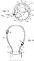
- Figs. 2, 3, 4 , 5 and 6are different schematic views of distal end 26 of probe 24, according to embodiments of the present invention.
- Fig. 2illustrates the probe distal end prior to exiting, or after reentering, the distal end of sheath 34.
- Fig. 3illustrates probe distal end 26 when it is exiting or reentering sheath 34.
- Figs. 4 and 5illustrate probe distal end 26 when it has completely exited sheath 34, in two different views.
- Fig. 6schematically illustrates, in cross-section, a single loop attached to distal end 26.
- Distal end 26comprises a plurality of flexible elastic filaments 100, each filament 100 being typically formed from a conductive element such as a nitinol tube. As is illustrated in Fig. 6 , each filament has two ends, 102, 104, both of which are fixed to distal end 26 of catheter 24, typically at a tip 110 of the distal end, so that each filament forms a loop. Distal end 26 of the catheter has an outer diameter d. If filaments 100 are conducting, for example if they are formed from nitinol, they are typically covered with an insulating material. Alternatively, filaments 100 may be formed from insulating material.
- Each filament 100has at least one electrode 28 fixed to the filament. If the filaments are in the form of a tube, conducting wires 116, insulated if filament 100 is conductive, may be attached through holes in the filaments to the electrodes, and the wires may be fed through and traverse a lumen of the tube (as illustrated in Fig. 6 ), via distal end 26 and proximal end 52 of catheter 24, to console 50. Signals acquired by the electrodes may thus be analyzed by processor 49. Alternatively, if filaments 100 are not tubular, wires 116 may be cemented to the outside of the filaments.
- the filamentsare fixed to distal end 26 so that the loops formed by each of the filaments intertwine to form an open lattice.
- the loops of the open latticeare arranged in a woven manner so that they interlace and cross each other, and so that they are able to slide against each other. Because of the elasticity of its constituent filaments, the open lattice may be in a compressed form as a compressed open lattice 118, illustrated in Fig. 2 .
- the open lattice of the filamentsmay also be in an uncompressed form as an uncompressed open lattice 120. Two views of open lattice 120 are provided in Fig. 4 and Fig. 5 .
- uncompressed open lattice 120has a predefined shape, which is sized to fit within a virtual envelope.
- open lattice 120it has a spherical shape and is sized so that it can be enclosed by a spherical virtual envelope 124.
- Uncompressed open lattice 120is formed of intertwined filaments 100, between which there are open spaces 130 ( Figs. 4 and 5 ).
- a ratio of a total area of the open spaces to a total area of filaments 100is at least 20:1, where both areas are defined as the area produced by projection, from a center of the virtual envelope, of the open spaces and of the filaments onto the envelope. In other embodiments the ratio may be at least 5:1.
- Uncompressed open lattice 120also has a lattice diameter D, which is the largest distance between any two sections of filaments 100 forming the lattice.
- lattice diameter Dmay alternatively be considered as the largest distance between points on the virtual envelope sized to enclose the uncompressed open lattice, so that in the case of spherical virtual envelope 124, lattice diameter D corresponds to the diameter of envelope 124.
- Lattice diameter Dis at least 5 times greater than outer diameter d of distal end 26 of the catheter, and is typically 20 times or more greater than d.
- sheath 34is initially inserted so that the distal end of the sheath is in a desired location with respect to heart 22.
- Filaments 100are compressed so that they form compressed open lattice 118, and so that the filaments are able to enter sheath 34.
- compressed open lattice 118is small enough to fit into a cylinder having the same diameter d as the outer diameter of the distal end 26.
- the lattice compressed form distal end 26 and its attached filamentsmay then be pushed into the sheath until it reaches the end of the sheath.
- Fig. 2schematically illustrates distal end 26 with its attached filaments 100 within sheath 34
- Fig. 3schematically illustrates the distal end and the filaments as the latter exit from the sheath.
- filaments 100decompress so that the filaments, in their uncompressed state, form uncompressed open lattice 120.
- distal end 26may be pulled in a proximal direction, so that filaments 100 are compressed by the sheath and reenter the sheath as compressed open lattice 118.
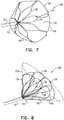
- Figs. 7 and 8are two views illustrating an uncompressed open lattice 220, according to an alternative embodiment of the present invention.
- uncompressed open lattice 220is generally similar to uncompressed open lattice 120 ( Figs. 4 and 5 ) and elements indicated by the same reference numerals in both lattices and in both sets of figures are generally similar in construction and in operation.
- lattice 220is formed from a plurality of intertwined filaments 100, each of the filaments having at least one electrode 28.
- Each of the filamentsis fixed by respective ends of the filaments to distal tip 110, so that each filament is in the form of a loop.
- uncompressed open lattice 120the predefined shape of uncompressed open lattice 220 is an open glove or cone, so that lattice 220 is sized to be enclosed by a conical virtual envelope 224.
- lattice 120lattice 220 has a lattice diameter D that is equal to the largest distance between any two sections of filaments 100 forming lattice 220. Alternatively, the lattice diameter may be considered as the largest distance between points on envelope 224.
- filaments 100 of uncompressed open lattice 220may be compressed to form a compressed open lattice which is able to enter sheath 34.
- embodiments of the present inventioncomprise other shapes, apart from the specific shapes described above with reference to uncompressed open lattices 120 and 220.
- uncompressed open latticesformed of filaments 100 fixed to distal tip 110, all of which lattices may compress to fit within sheath 24, are in the form of an ellipsoid or a paraboloid. All such open lattices are assumed to be comprised within the scope of the present invention.
Landscapes
- Health & Medical Sciences (AREA)
- Life Sciences & Earth Sciences (AREA)
- Engineering & Computer Science (AREA)
- Surgery (AREA)
- Heart & Thoracic Surgery (AREA)
- Public Health (AREA)
- General Health & Medical Sciences (AREA)
- Animal Behavior & Ethology (AREA)
- Veterinary Medicine (AREA)
- Biomedical Technology (AREA)
- Molecular Biology (AREA)
- Medical Informatics (AREA)
- Physics & Mathematics (AREA)
- Biophysics (AREA)
- Pathology (AREA)
- Cardiology (AREA)
- Otolaryngology (AREA)
- Nuclear Medicine, Radiotherapy & Molecular Imaging (AREA)
- Plasma & Fusion (AREA)
- Physiology (AREA)
- Mechanical Engineering (AREA)
- Pulmonology (AREA)
- Anesthesiology (AREA)
- Hematology (AREA)
- Surgical Instruments (AREA)
- Measurement And Recording Of Electrical Phenomena And Electrical Characteristics Of The Living Body (AREA)
- Media Introduction/Drainage Providing Device (AREA)
Description
- The present invention relates generally to catheters, and specifically to formation of the distal end of a catheter.
- During a medical procedure on the heart, such as an ablation, the energy for the ablation may be radiofrequency energy that is injected into the heart via electrodes contacting the heart. The electrodes, or other electrodes, may also be used to monitor the condition of the heart, by acquiring signals from the heart as it beats. Present day ablation procedures typically use a relatively large number of electrodes simultaneously, and such electrodes may be provided in specially designed catheters, such as basket, pent-array or lasso catheters.
WO 2015/187430 , published after the priority date of the present application, and prior art under Article 54(3) EPC, discusses an expandable electrode assembly which includes multiple bipolar electrode pairs including a first electrode located on an outer surface and a second electrode located on an inner surface of the individual splines forming the expandable electrode assembly. Such an electrode arrangement may produce improved electrical activation signals which may be used to produce a more accurate map of the electrical activity of a patient's heart.US 6,514,249 discusses a tissue ablation device assembly and method using a circumferential ablation member in combination with a position monitoring assembly in order to position the circumferential ablation member along a circumferential region of tissue at a location where a pulmonary vein extends from a left atrium.US 2006/089637 discusses devices, systems and methods are for the ablation of tissue, including an ablation catheter which has an array of ablation elements attached to a deployable carrier assembly. The carrier assembly can be constrained within the lumen of a catheter, and deployed to take on an expanded condition.US 2013/0190587 discusses a high-density electrode based medical device system, which may be achieved, at least in part, by overlapping elongate members on which the electrodes are located. The elongate members may be arranged in a structure which is moveable between an unexpanded configuration, which is suitable for percutaneous delivery through a bodily opening to a bodily cavity, and an expanded configuration, which is not.- The present invention provides an apparatus, including:
- a catheter having a distal end and a predefined outer diameter; and
- a plurality of elastic filaments, each filament having at least one electrode fixed thereto and having two ends fixed within the catheter distal end to hold the filament as a loop. The loop intertwines with one or more other loops of the other filaments so that the plurality of the filaments forms an open lattice, which expands when uncompressed to a lattice diameter at least five times greater than the outer diameter of the catheter wherein:
- the lattice diameter comprises a largest distance between selected sections of the plurality of elastic filaments;
- the open lattice when uncompressed comprises open spaces between the intertwined filaments ; and a ratio of a first total area defined by the open spaces and a second total area defined by the filaments is at least 5:1.
- Typically, the open lattice compresses to fit within a cylinder having a diameter equal to the predefined outer diameter of the catheter.
- In a disclosed embodiment the open lattice when uncompressed has a spherical shape. Alternatively, the open lattice when uncompressed is an open glove or cone. In a yet further disclosed embodiment each elastic filament consists of a tube having a lumen, and the at least one electrode is attached to a conductive wire traversing the lumen.
- There is further provided, according to the present invention, a method, including:
- providing a catheter with a distal end and a predefined outer diameter; and
- fixing a plurality of elastic filaments within the catheter distal end, each filament having at least one electrode fixed thereto and having two ends fixed within the catheter distal end to hold the filament as a loop, wherein the loop intertwines with one or more other loops of the other filaments so that the plurality of the filaments forms an open lattice, and wherein the open lattice expands when uncompressed to a lattice diameter at least five times greater than the outer diameter of the catheter, wherein:
- the lattice diameter comprises a largest distance between selected sections of the plurality of elastic filaments;
- the open lattice when uncompressed comprises open spaces between the intertwined filaments; and
- a ratio of a first total area defined by the open spaces and a second total area defined by the filaments is at least 5:1.
- fixing a plurality of elastic filaments within the catheter distal end, each filament having at least one electrode fixed thereto and having two ends fixed within the catheter distal end to hold the filament as a loop, wherein the loop intertwines with one or more other loops of the other filaments so that the plurality of the filaments forms an open lattice, and wherein the open lattice expands when uncompressed to a lattice diameter at least five times greater than the outer diameter of the catheter, wherein:
- The present disclosure will be more fully understood from the following detailed description of the embodiments thereof, taken together with the drawings, in which:
Fig. 1 is a schematic illustration of a minimally invasive medical system, according to an embodiment of the present invention;Figs. 2, 3, 4 ,5 and 6 are different schematic views of a distal end of a probe, according to embodiments of the present invention; andFigs. 7 and 8 are two views illustrating an uncompressed open lattice, according to an alternative embodiment of the present invention.- Many catheters, such as pent-array, lasso, or basket catheters, may push the heart wall when attempting to conform to the shape of the wall during a medical procedure, such as an ablation, performed on the wall. In addition, these types of catheters have relatively sharp regions (the ends of the splines in the case of a pent-array or lasso catheter; the distal end of the basket in the case of a basket catheter). For catheters with open ended constructions, such as the pent-array or lasso catheters, it is difficult to maintain their shape during operation. (In the pent-array catheter the ends tend to overlap; in the lasso catheter the lasso end tends to entangle with the remainder of the lasso, and relatively large forces are required to counteract these effects.) For all these types of catheters the combination of the required force and sharp regions may have undesired results during use of the catheters in medical procedures such as those referred to above.
- Embodiments of the present invention overcome both of the problems. A plurality of elastic filaments are attached to the distal end of a catheter, each filament having fixed to it at least one electrode. The two ends of each filament are fixed within the catheter, typically within the distal tip of the distal end, so that each filament forms a loop with no sharp regions. The loops formed by the filaments are configured to intertwine in a woven manner with each other, so that the plurality of the filaments form an open lattice. The elasticity of the filaments allows the open lattice to exist in a compressed or in an uncompressed form.
- In the compressed form, the catheter with its compressed open lattice may be inserted into a sheath that guides the distal end of the catheter to a desired location, typically in the heart during a procedure being performed on the heart. At the desired location the compressed open lattice exits the sheath, and decompresses to form an uncompressed open lattice.
- The uncompressed open lattice is relatively large, having a lattice diameter at least five times larger than the outer diameter of the catheter distal end, so that the electrodes of the lattice are able to contact the heart wall. However, the elasticity of the filaments, and their lack of sharp edges, prevents trauma to the heart.
- By having the loops of the filaments intertwine with, and cross, each other, in the woven manner referred to above, the uncompressed open lattice formed by the loops is able to maintain its shape.
- Reference is now made to
Fig. 1 , which is a schematic illustration of a minimally invasivemedical system 20, according to an embodiment of the present invention.System 20 is typically used during a medical procedure on a body organ, and in the description herein the body organ, by way of example, is assumed to comprise the heart, wherein the system is applied to sample, and typically record and analyze, intra-cardiac electrocardiogram (ECG) signals. However, it will be understood thatsystem 20 may be applied to sample other signals from other body organs. - The following description assumes that
system 20 senses intra-cardiac ECG signals from aheart 22, using aprobe 24.Probe 24 typically comprises a catheter, and is herein also referred to ascatheter 24. Adistal end 26 of the probe is inserted into the body of asubject 30.Distal end 26 of the probe, described in more detail below, comprises a plurality ofelectrodes 28 which sense the ECG signals. Prior to insertion of the probe intoheart 22, asheath 34 may be inserted into the subject until the distal end of the sheath is in a desired location. Once the distal end of the sheath has been correctly positioned,probe 24 may be inserted intosheath 34 untildistal end 26 of the probe exits from the distal end of the sheath. In the description herein auser 32, typically a medical professional, is assumed to insert the sheath and the probe. System 20 may be controlled by asystem processor 40, comprising aprocessing unit 42 communicating with anECG module 44.Processor 40 may be mounted in aconsole 50, which comprises operating controls which typically include a pointing device such as a mouse or trackball. Console 50 also connects to other elements ofsystem 20, such as aproximal end 52 ofcatheter 24. Professional 32 uses the pointing device to interact with the processor, which, as described below, may be used to present results produced bysystem 20 to the professional on ascreen 54.- The screen displays results of analysis and processing of ECG signals by
ECG module 44. Typically, the resultant ECG signals are presented onscreen 54 in the form of a potential vs. time graph, and a schematic example 60 of such a graph is illustrated inFig. 1 . However, the resultant ECG signals may also be used byprocessor 40 to derive other results associated with the ECG signals, such as a local activation time (LAT). These results are typically presented onscreen 54 in the form of a three-dimensional (3D)map 64 of the internal surface ofheart 22. Processor 40 uses software stored in a memory of the processor to operatesystem 20. The software may be downloaded toprocessor 40 in electronic form, over a network, for example, or it may, alternatively or additionally, be provided and/or stored on non-transitory tangible media, such as magnetic, optical, or electronic memory.Processor 40 typically comprises other modules, such as a probe tracking module and an ablation module that provides regulated power to one ormore electrodes 28, or to one or more other electrodes in the distal end. For simplicity, such modules are not shown inFig. 1 . The Carto® system produced by Biosense Webster, of Diamond Bar, CA, uses such modules.Figs. 2, 3, 4 ,5 and 6 are different schematic views ofdistal end 26 ofprobe 24, according to embodiments of the present invention.Fig. 2 illustrates the probe distal end prior to exiting, or after reentering, the distal end ofsheath 34.Fig. 3 illustrates probedistal end 26 when it is exiting or reenteringsheath 34.Figs. 4 and5 illustrate probedistal end 26 when it has completely exitedsheath 34, in two different views.Fig. 6 schematically illustrates, in cross-section, a single loop attached todistal end 26.Distal end 26 comprises a plurality of flexibleelastic filaments 100, eachfilament 100 being typically formed from a conductive element such as a nitinol tube. As is illustrated inFig. 6 , each filament has two ends, 102, 104, both of which are fixed todistal end 26 ofcatheter 24, typically at atip 110 of the distal end, so that each filament forms a loop.Distal end 26 of the catheter has an outer diameter d. Iffilaments 100 are conducting, for example if they are formed from nitinol, they are typically covered with an insulating material. Alternatively,filaments 100 may be formed from insulating material.- Each
filament 100 has at least oneelectrode 28 fixed to the filament. If the filaments are in the form of a tube, conductingwires 116, insulated iffilament 100 is conductive, may be attached through holes in the filaments to the electrodes, and the wires may be fed through and traverse a lumen of the tube (as illustrated inFig. 6 ), viadistal end 26 andproximal end 52 ofcatheter 24, to console 50. Signals acquired by the electrodes may thus be analyzed by processor 49. Alternatively, iffilaments 100 are not tubular,wires 116 may be cemented to the outside of the filaments. - The filaments are fixed to
distal end 26 so that the loops formed by each of the filaments intertwine to form an open lattice. The loops of the open lattice are arranged in a woven manner so that they interlace and cross each other, and so that they are able to slide against each other. Because of the elasticity of its constituent filaments, the open lattice may be in a compressed form as a compressedopen lattice 118, illustrated inFig. 2 . The open lattice of the filaments may also be in an uncompressed form as an uncompressedopen lattice 120. Two views ofopen lattice 120 are provided inFig. 4 andFig. 5 . When the filaments are fixed to the distal end, they are arranged so that uncompressedopen lattice 120 has a predefined shape, which is sized to fit within a virtual envelope. In the case ofopen lattice 120, it has a spherical shape and is sized so that it can be enclosed by a sphericalvirtual envelope 124. - Uncompressed
open lattice 120 is formed of intertwinedfilaments 100, between which there are open spaces 130 (Figs. 4 and5 ). In one embodiment, a ratio of a total area of the open spaces to a total area offilaments 100 is at least 20:1, where both areas are defined as the area produced by projection, from a center of the virtual envelope, of the open spaces and of the filaments onto the envelope. In other embodiments the ratio may be at least 5:1. - Uncompressed
open lattice 120 also has a lattice diameter D, which is the largest distance between any two sections offilaments 100 forming the lattice. In some embodiments lattice diameter D may alternatively be considered as the largest distance between points on the virtual envelope sized to enclose the uncompressed open lattice, so that in the case of sphericalvirtual envelope 124, lattice diameter D corresponds to the diameter ofenvelope 124. Lattice diameter D is at least 5 times greater than outer diameter d ofdistal end 26 of the catheter, and is typically 20 times or more greater than d. - As stated above, in a typical cardiac
procedure using system 20,sheath 34 is initially inserted so that the distal end of the sheath is in a desired location with respect toheart 22.Filaments 100 are compressed so that they form compressedopen lattice 118, and so that the filaments are able to entersheath 34. In some embodiments compressedopen lattice 118 is small enough to fit into a cylinder having the same diameter d as the outer diameter of thedistal end 26. In it's the lattice compressed formdistal end 26 and its attached filaments may then be pushed into the sheath until it reaches the end of the sheath.Fig. 2 schematically illustratesdistal end 26 with its attachedfilaments 100 withinsheath 34, andFig. 3 schematically illustrates the distal end and the filaments as the latter exit from the sheath. - After exiting from the sheath,
filaments 100 decompress so that the filaments, in their uncompressed state, form uncompressedopen lattice 120. At the termination of the procedure,distal end 26 may be pulled in a proximal direction, so thatfilaments 100 are compressed by the sheath and reenter the sheath as compressedopen lattice 118. Figs. 7 and 8 are two views illustrating an uncompressedopen lattice 220, according to an alternative embodiment of the present invention. Apart from the differences described below, uncompressedopen lattice 220 is generally similar to uncompressed open lattice 120 (Figs. 4 and5 ) and elements indicated by the same reference numerals in both lattices and in both sets of figures are generally similar in construction and in operation. Thuslattice 220 is formed from a plurality of intertwinedfilaments 100, each of the filaments having at least oneelectrode 28. Each of the filaments is fixed by respective ends of the filaments todistal tip 110, so that each filament is in the form of a loop. There arespaces 130 betweenintertwined filaments 100.- However, in contrast to uncompressed
open lattice 120, the predefined shape of uncompressedopen lattice 220 is an open glove or cone, so thatlattice 220 is sized to be enclosed by a conicalvirtual envelope 224. As forlattice 120,lattice 220 has a lattice diameter D that is equal to the largest distance between any two sections offilaments 100 forminglattice 220. Alternatively, the lattice diameter may be considered as the largest distance between points onenvelope 224. As forlattice 120,filaments 100 of uncompressedopen lattice 220 may be compressed to form a compressed open lattice which is able to entersheath 34. - It will be understood that embodiments of the present invention comprise other shapes, apart from the specific shapes described above with reference to uncompressed
open lattices filaments 100 fixed todistal tip 110, all of which lattices may compress to fit withinsheath 24, are in the form of an ellipsoid or a paraboloid. All such open lattices are assumed to be comprised within the scope of the present invention. - It will thus be appreciated that the embodiments described above are cited by way of example, and that the present invention is not limited to what has been particularly shown and described hereinabove. Rather, the scope of the present invention is defined by the claims.
Claims (10)
- Apparatus, comprising:a catheter (24) having a distal end (26) and a predefined outer diameter (d); anda plurality of elastic filaments (100), each filament having at least one electrode (28) fixed thereto and having two ends (102, 104) fixed within the catheter distal end to hold the filament as a loop, which intertwines with one or more other loops of the other filaments so that the plurality of the filaments forms an open lattice (120, 220), which expands when uncompressed to a lattice diameter (D) at least five times greater than the outer diameter of the catheter, wherein:the lattice diameter (D) comprises a largest distance between selected sections of the plurality of elastic filaments;the open lattice (120, 220) when uncompressed comprises open spaces (130) between the intertwined filaments (100); anda ratio of a first total area defined by the open spaces and a second total area defined by the filaments is at least 5:1.
- The apparatus according to claim 1, wherein the open lattice (120, 220) compresses to fit within a cylinder (34) having a diameter equal to the predefined outer diameter of the catheter (d).
- The apparatus according to claim 1, wherein the open lattice (120) when uncompressed has a spherical shape.
- The apparatus according to claim 1, wherein the predefined shape of the open lattice (220) when uncompressed is an open glove or cone.
- The apparatus according to claim 1, wherein each elastic filament (100) comprises a tube having a lumen, and wherein the at least one electrode (28) is attached to a conductive wire (116) traversing the lumen.
- A method, comprising:providing a catheter (24) with a distal end (26) and a predefined outer diameter (d); andfixing a plurality of elastic filaments (100) within the catheter distal end, each filament having at least one electrode (28) fixed thereto and having two ends (102, 104) fixed within the catheter distal end to hold the filament as a loop, wherein the loop intertwines with one or more other loops of the other filaments so that the plurality of the filaments forms an open lattice (120, 220), and wherein the open lattice expands when uncompressed to a lattice diameter (D) at least five times greater than the outer diameter of the catheter, wherein:the lattice diameter (D) comprises a largest distance between selected sections of the plurality of elastic filaments;the open lattice (120, 220) when uncompressed comprises open spaces (130) between the intertwined filaments (100); anda ratio of a first total area defined by the open spaces and a second total area defined by the filaments is at least 5:1.
- The method according to claim 6, wherein the open lattice (120, 220) compresses to fit within a cylinder (34) having a diameter equal to the predefined outer diameter of the catheter (d).
- The method according to claim 6, wherein the open lattice (120) when uncompressed has a spherical shape.
- The method according to claim 6, wherein the open lattice (220) when uncompressed is an open glove or cone.
- The method according to claim 6, wherein each elastic filament (100) comprises a tube having a lumen, and wherein the at least one electrode (28) is attached to a conductive wire (116) traversing the lumen.
Priority Applications (1)
| Application Number | Priority Date | Filing Date | Title |
|---|---|---|---|
| EP18167661.0AEP3366251B1 (en) | 2015-05-19 | 2016-05-18 | Woven foldable catheter |
Applications Claiming Priority (1)
| Application Number | Priority Date | Filing Date | Title |
|---|---|---|---|
| US14/715,958US20160338770A1 (en) | 2015-05-19 | 2015-05-19 | Woven foldable catheter |
Related Child Applications (1)
| Application Number | Title | Priority Date | Filing Date |
|---|---|---|---|
| EP18167661.0ADivisionEP3366251B1 (en) | 2015-05-19 | 2016-05-18 | Woven foldable catheter |
Publications (2)
| Publication Number | Publication Date |
|---|---|
| EP3095405A1 EP3095405A1 (en) | 2016-11-23 |
| EP3095405B1true EP3095405B1 (en) | 2018-04-18 |
Family
ID=56014909
Family Applications (2)
| Application Number | Title | Priority Date | Filing Date |
|---|---|---|---|
| EP16170154.5ANot-in-forceEP3095405B1 (en) | 2015-05-19 | 2016-05-18 | Woven foldable catheter |
| EP18167661.0AActiveEP3366251B1 (en) | 2015-05-19 | 2016-05-18 | Woven foldable catheter |
Family Applications After (1)
| Application Number | Title | Priority Date | Filing Date |
|---|---|---|---|
| EP18167661.0AActiveEP3366251B1 (en) | 2015-05-19 | 2016-05-18 | Woven foldable catheter |
Country Status (8)
| Country | Link |
|---|---|
| US (1) | US20160338770A1 (en) |
| EP (2) | EP3095405B1 (en) |
| JP (2) | JP2016214865A (en) |
| CN (1) | CN106166319A (en) |
| AU (1) | AU2016202564A1 (en) |
| CA (1) | CA2928230A1 (en) |
| ES (1) | ES2758097T3 (en) |
| IL (1) | IL245248B (en) |
Families Citing this family (45)
| Publication number | Priority date | Publication date | Assignee | Title |
|---|---|---|---|---|
| WO2015192018A1 (en) | 2014-06-12 | 2015-12-17 | Iowa Approach Inc. | Method and apparatus for rapid and selective tissue ablation with cooling |
| EP3154463B1 (en) | 2014-06-12 | 2019-03-27 | Farapulse, Inc. | Apparatus for rapid and selective transurethral tissue ablation |
| EP3206613B1 (en) | 2014-10-14 | 2019-07-03 | Farapulse, Inc. | Apparatus for rapid and safe pulmonary vein cardiac ablation |
| US10130423B1 (en) | 2017-07-06 | 2018-11-20 | Farapulse, Inc. | Systems, devices, and methods for focal ablation |
| US20170189097A1 (en) | 2016-01-05 | 2017-07-06 | Iowa Approach Inc. | Systems, apparatuses and methods for delivery of ablative energy to tissue |
| US10660702B2 (en) | 2016-01-05 | 2020-05-26 | Farapulse, Inc. | Systems, devices, and methods for focal ablation |
| US10172673B2 (en) | 2016-01-05 | 2019-01-08 | Farapulse, Inc. | Systems devices, and methods for delivery of pulsed electric field ablative energy to endocardial tissue |
| US12144541B2 (en) | 2016-01-05 | 2024-11-19 | Boston Scientific Scimed, Inc. | Systems, apparatuses and methods for delivery of ablative energy to tissue |
| US10905329B2 (en) | 2016-06-09 | 2021-02-02 | Biosense Webster (Israel) Ltd. | Multi-function conducting elements for a catheter |
| US11344259B2 (en)* | 2017-01-11 | 2022-05-31 | Abbott Cardiovascular Systems Inc. | Expandable member for an electrophysiology catheter |
| US9987081B1 (en) | 2017-04-27 | 2018-06-05 | Iowa Approach, Inc. | Systems, devices, and methods for signal generation |
| US12029545B2 (en) | 2017-05-30 | 2024-07-09 | Biosense Webster (Israel) Ltd. | Catheter splines as location sensors |
| JP7586706B2 (en) | 2017-09-12 | 2024-11-19 | ボストン サイエンティフィック サイムド,インコーポレイテッド | Systems, devices and methods for focal ventricular ablation - Patents.com |
| EP3749191A1 (en)* | 2018-02-06 | 2020-12-16 | Biosense Webster (Israel) Ltd | Medical probe with staggered microelectrode configuration |
| US20190314083A1 (en) | 2018-04-11 | 2019-10-17 | Biosense Webster (Israel) Ltd. | Flexible Multi-Arm Catheter with Diametrically Opposed Sensing Electrodes |
| WO2019217433A1 (en) | 2018-05-07 | 2019-11-14 | Farapulse, Inc. | Systems, apparatuses and methods for delivery of ablative energy to tissue |
| US11642165B2 (en)* | 2018-06-29 | 2023-05-09 | Biosense Webster (Israel) Ltd. | Catheter with mechanically expandable element having flex circuit |
| US10687892B2 (en) | 2018-09-20 | 2020-06-23 | Farapulse, Inc. | Systems, apparatuses, and methods for delivery of pulsed electric field ablative energy to endocardial tissue |
| US11045628B2 (en) | 2018-12-11 | 2021-06-29 | Biosense Webster (Israel) Ltd. | Balloon catheter with high articulation |
| US11547473B2 (en)* | 2018-12-11 | 2023-01-10 | Neurent Medical Limited | Systems and methods for therapeutic nasal neuromodulation |
| US11207016B2 (en) | 2018-12-28 | 2021-12-28 | Biosense Webster (Israel) Ltd. | Mapping ECG signals using a multipole electrode assembly |
| US11850051B2 (en) | 2019-04-30 | 2023-12-26 | Biosense Webster (Israel) Ltd. | Mapping grid with high density electrode array |
| US11540878B2 (en)* | 2019-07-17 | 2023-01-03 | Biosense Webster (Israel) Ltd. | Blooming leaflet catheter with high density electrode array |
| US11712172B2 (en) | 2019-07-18 | 2023-08-01 | Biosense Webster (Israel) Ltd. | Visual guidance for positioning a distal end of a medical probe |
| US11950930B2 (en) | 2019-12-12 | 2024-04-09 | Biosense Webster (Israel) Ltd. | Multi-dimensional acquisition of bipolar signals from a catheter |
| US11517218B2 (en) | 2019-12-20 | 2022-12-06 | Biosense Webster (Israel) Ltd. | Selective graphical presentation of electrophysiological parameters |
| US12232874B2 (en) | 2020-05-29 | 2025-02-25 | Biosense Webster (Israel) Ltd. | Electrode apparatus for diagnosis of arrhythmias |
| US11987017B2 (en) | 2020-06-08 | 2024-05-21 | Biosense Webster (Israel) Ltd. | Features to assist in assembly and testing of devices |
| US12310652B2 (en) | 2020-07-24 | 2025-05-27 | Boston Scientific Scimed, Inc. | Hybrid electroporation ablation catheter |
| WO2022020478A1 (en) | 2020-07-24 | 2022-01-27 | Boston Scientific Scimed Inc | Electric field application for single shot cardiac ablation by irreversible electroporation |
| US12048479B2 (en) | 2020-09-10 | 2024-07-30 | Biosense Webster (Israel) Ltd. | Surface mounted electrode catheter |
| US11950841B2 (en) | 2020-09-22 | 2024-04-09 | Biosense Webster (Israel) Ltd. | Basket catheter having insulated ablation electrodes and diagnostic electrodes |
| US11950840B2 (en) | 2020-09-22 | 2024-04-09 | Biosense Webster (Israel) Ltd. | Basket catheter having insulated ablation electrodes |
| US12082875B2 (en) | 2020-09-24 | 2024-09-10 | Biosense Webster (Israel) Ltd | Balloon catheter having a coil for sensing tissue temperature and position of the balloon |
| US11974803B2 (en) | 2020-10-12 | 2024-05-07 | Biosense Webster (Israel) Ltd. | Basket catheter with balloon |
| US12201786B2 (en) | 2020-12-17 | 2025-01-21 | Biosense Webster (Israel) Ltd. | Measurement of distal end dimension of catheters using magnetic fields |
| US11918383B2 (en) | 2020-12-21 | 2024-03-05 | Biosense Webster (Israel) Ltd. | Visualizing performance of catheter electrodes |
| JP2024504184A (en) | 2021-01-27 | 2024-01-30 | ボストン サイエンティフィック サイムド,インコーポレイテッド | Voltage-controlled pulse sequence for irreversible electroporation ablation |
| AU2022234310A1 (en)* | 2021-03-10 | 2023-09-28 | Cardiofocus, Inc. | Devices for the delivery of pulsed electric fields in the treatment of cardiac tissue |
| US12064170B2 (en) | 2021-05-13 | 2024-08-20 | Biosense Webster (Israel) Ltd. | Distal assembly for catheter with lumens running along spines |
| US12364426B2 (en) | 2021-08-12 | 2025-07-22 | Biosense Webster (Israel) Ltd. | Electro-anatomical mapping and annotation presented in electrophysiological procedures |
| US12004804B2 (en) | 2021-09-09 | 2024-06-11 | Biosense Webster (Israel) Ltd. | Basket catheter with mushroom shape distal tip |
| US12011280B2 (en) | 2021-10-04 | 2024-06-18 | Biosense Webster (Israel) Ltd. | Electrophysiological mapping in the presence of injury current |
| US12419683B2 (en) | 2021-12-22 | 2025-09-23 | Biosense Webster (Israel) Ltd. | Irreversible electroporation with shorted electrodes |
| US20240197391A1 (en)* | 2022-12-15 | 2024-06-20 | Biosense Webster (Israel) Ltd. | Basket assembly with atraumatic tip electrode and methods of making thereof |
Citations (1)
| Publication number | Priority date | Publication date | Assignee | Title |
|---|---|---|---|---|
| US20130190587A1 (en)* | 2011-01-21 | 2013-07-25 | Kardium Inc. | High-density electrode-based medical device system |
Family Cites Families (11)
| Publication number | Priority date | Publication date | Assignee | Title |
|---|---|---|---|---|
| US6514249B1 (en)* | 1997-07-08 | 2003-02-04 | Atrionix, Inc. | Positioning system and method for orienting an ablation element within a pulmonary vein ostium |
| US6428537B1 (en)* | 1998-05-22 | 2002-08-06 | Scimed Life Systems, Inc. | Electrophysiological treatment methods and apparatus employing high voltage pulse to render tissue temporarily unresponsive |
| JP2002126096A (en)* | 2000-10-27 | 2002-05-08 | Aisin Seiki Co Ltd | Catheter equipped with electrode |
| US8007495B2 (en)* | 2004-03-31 | 2011-08-30 | Biosense Webster, Inc. | Catheter for circumferential ablation at or near a pulmonary vein |
| US20060089637A1 (en)* | 2004-10-14 | 2006-04-27 | Werneth Randell L | Ablation catheter |
| US8224416B2 (en)* | 2007-05-09 | 2012-07-17 | St. Jude Medical, Atrial Fibrillation Division, Inc. | Basket catheter having multiple electrodes |
| EP2699153B1 (en)* | 2011-04-22 | 2015-12-16 | Topera, Inc. | Flexible electrode assembly for insertion into body lumen or organ |
| US10314649B2 (en)* | 2012-08-02 | 2019-06-11 | Ethicon Endo-Surgery, Inc. | Flexible expandable electrode and method of intraluminal delivery of pulsed power |
| EP2890292B1 (en)* | 2012-08-31 | 2021-01-13 | Acutus Medical, Inc. | Catheter system for the heart |
| US9848795B2 (en)* | 2014-06-04 | 2017-12-26 | Boston Scientific Scimed Inc. | Electrode assembly |
| CN106687168A (en)* | 2014-09-12 | 2017-05-17 | X-节奏有限责任公司 | Multi-electrode mapping catheter |
- 2015
- 2015-05-19USUS14/715,958patent/US20160338770A1/ennot_activeAbandoned
- 2016
- 2016-04-20ILIL245248Apatent/IL245248B/enactiveIP Right Grant
- 2016-04-22AUAU2016202564Apatent/AU2016202564A1/ennot_activeWithdrawn
- 2016-04-26CACA2928230Apatent/CA2928230A1/ennot_activeAbandoned
- 2016-05-18JPJP2016099474Apatent/JP2016214865A/enactivePending
- 2016-05-18CNCN201610330330.6Apatent/CN106166319A/enactivePending
- 2016-05-18EPEP16170154.5Apatent/EP3095405B1/ennot_activeNot-in-force
- 2016-05-18ESES18167661Tpatent/ES2758097T3/enactiveActive
- 2016-05-18EPEP18167661.0Apatent/EP3366251B1/enactiveActive
- 2021
- 2021-04-28JPJP2021075916Apatent/JP2021106984A/enactivePending
Patent Citations (1)
| Publication number | Priority date | Publication date | Assignee | Title |
|---|---|---|---|---|
| US20130190587A1 (en)* | 2011-01-21 | 2013-07-25 | Kardium Inc. | High-density electrode-based medical device system |
Also Published As
| Publication number | Publication date |
|---|---|
| US20160338770A1 (en) | 2016-11-24 |
| EP3095405A1 (en) | 2016-11-23 |
| EP3366251B1 (en) | 2019-09-04 |
| JP2021106984A (en) | 2021-07-29 |
| CN106166319A (en) | 2016-11-30 |
| EP3366251A1 (en) | 2018-08-29 |
| AU2016202564A1 (en) | 2016-12-08 |
| ES2758097T3 (en) | 2020-05-04 |
| JP2016214865A (en) | 2016-12-22 |
| CA2928230A1 (en) | 2016-11-19 |
| IL245248B (en) | 2019-12-31 |
| IL245248A0 (en) | 2016-08-31 |
Similar Documents
| Publication | Publication Date | Title |
|---|---|---|
| EP3095405B1 (en) | Woven foldable catheter | |
| US10362991B2 (en) | Convertible basket catheter | |
| EP3672532B1 (en) | Implantable cardiac pacing system | |
| US20220117735A1 (en) | Annuloplasty procedures, related devices and methods | |
| US12336825B2 (en) | Basket style cardiac mapping catheter having a flexible electrode assembly for detection of cardiac rhythm disorders | |
| US11039923B2 (en) | Annuloplasty procedures, related devices and methods | |
| DE60215757T2 (en) | Systems for atrial defibrillation | |
| EP2907462B1 (en) | Catheter with transverse branches | |
| US10974031B2 (en) | Balloon catheter with internal distal end | |
| EP3178385A1 (en) | Electrode array catheter with interconnected framework | |
| US20180085064A1 (en) | Basket catheter conforming to organ using strain-relief elements | |
| US20080058794A1 (en) | Electrophysiology System for Mapping and Ablating Arrhythmias | |
| US11007059B2 (en) | Annuloplasty procedures, related devices and methods | |
| US20100198041A1 (en) | Apparatus and method for positioning and retention of catheter | |
| CN105796090A (en) | Basket catheter with improved spine flexibility | |
| EP3973903B1 (en) | Basket catheter having insulated ablation electrodes and diagnostic electrodes | |
| CN110072474A (en) | The equipment and associated insertion type medical system in channel are formed in the tissue | |
| EP3977954B1 (en) | Basket catheter having insulated ablation electrodes | |
| US20230210433A1 (en) | Reconfigurable electrode apparatus for diagnosis of arrhythmias | |
| CN117120138A (en) | Transvenous intracardiac pacing catheter |
Legal Events
| Date | Code | Title | Description |
|---|---|---|---|
| PUAI | Public reference made under article 153(3) epc to a published international application that has entered the european phase | Free format text:ORIGINAL CODE: 0009012 | |
| AK | Designated contracting states | Kind code of ref document:A1 Designated state(s):AL AT BE BG CH CY CZ DE DK EE ES FI FR GB GR HR HU IE IS IT LI LT LU LV MC MK MT NL NO PL PT RO RS SE SI SK SM TR | |
| AX | Request for extension of the european patent | Extension state:BA ME | |
| 17P | Request for examination filed | Effective date:20170519 | |
| RBV | Designated contracting states (corrected) | Designated state(s):AL AT BE BG CH CY CZ DE DK EE ES FI FR GB GR HR HU IE IS IT LI LT LU LV MC MK MT NL NO PL PT RO RS SE SI SK SM TR | |
| GRAP | Despatch of communication of intention to grant a patent | Free format text:ORIGINAL CODE: EPIDOSNIGR1 | |
| INTG | Intention to grant announced | Effective date:20170712 | |
| GRAJ | Information related to disapproval of communication of intention to grant by the applicant or resumption of examination proceedings by the epo deleted | Free format text:ORIGINAL CODE: EPIDOSDIGR1 | |
| GRAP | Despatch of communication of intention to grant a patent | Free format text:ORIGINAL CODE: EPIDOSNIGR1 | |
| INTC | Intention to grant announced (deleted) | ||
| INTG | Intention to grant announced | Effective date:20171211 | |
| GRAS | Grant fee paid | Free format text:ORIGINAL CODE: EPIDOSNIGR3 | |
| GRAA | (expected) grant | Free format text:ORIGINAL CODE: 0009210 | |
| AK | Designated contracting states | Kind code of ref document:B1 Designated state(s):AL AT BE BG CH CY CZ DE DK EE ES FI FR GB GR HR HU IE IS IT LI LT LU LV MC MK MT NL NO PL PT RO RS SE SI SK SM TR | |
| REG | Reference to a national code | Ref country code:GB Ref legal event code:FG4D | |
| REG | Reference to a national code | Ref country code:CH Ref legal event code:EP | |
| REG | Reference to a national code | Ref country code:AT Ref legal event code:REF Ref document number:989592 Country of ref document:AT Kind code of ref document:T Effective date:20180515 | |
| REG | Reference to a national code | Ref country code:IE Ref legal event code:FG4D | |
| REG | Reference to a national code | Ref country code:DE Ref legal event code:R096 Ref document number:602016002499 Country of ref document:DE | |
| REG | Reference to a national code | Ref country code:FR Ref legal event code:PLFP Year of fee payment:3 | |
| REG | Reference to a national code | Ref country code:NL Ref legal event code:FP | |
| REG | Reference to a national code | Ref country code:LT Ref legal event code:MG4D | |
| PG25 | Lapsed in a contracting state [announced via postgrant information from national office to epo] | Ref country code:ES Free format text:LAPSE BECAUSE OF FAILURE TO SUBMIT A TRANSLATION OF THE DESCRIPTION OR TO PAY THE FEE WITHIN THE PRESCRIBED TIME-LIMIT Effective date:20180418 Ref country code:LT Free format text:LAPSE BECAUSE OF FAILURE TO SUBMIT A TRANSLATION OF THE DESCRIPTION OR TO PAY THE FEE WITHIN THE PRESCRIBED TIME-LIMIT Effective date:20180418 Ref country code:FI Free format text:LAPSE BECAUSE OF FAILURE TO SUBMIT A TRANSLATION OF THE DESCRIPTION OR TO PAY THE FEE WITHIN THE PRESCRIBED TIME-LIMIT Effective date:20180418 Ref country code:PL Free format text:LAPSE BECAUSE OF FAILURE TO SUBMIT A TRANSLATION OF THE DESCRIPTION OR TO PAY THE FEE WITHIN THE PRESCRIBED TIME-LIMIT Effective date:20180418 Ref country code:BG Free format text:LAPSE BECAUSE OF FAILURE TO SUBMIT A TRANSLATION OF THE DESCRIPTION OR TO PAY THE FEE WITHIN THE PRESCRIBED TIME-LIMIT Effective date:20180718 Ref country code:SE Free format text:LAPSE BECAUSE OF FAILURE TO SUBMIT A TRANSLATION OF THE DESCRIPTION OR TO PAY THE FEE WITHIN THE PRESCRIBED TIME-LIMIT Effective date:20180418 Ref country code:NO Free format text:LAPSE BECAUSE OF FAILURE TO SUBMIT A TRANSLATION OF THE DESCRIPTION OR TO PAY THE FEE WITHIN THE PRESCRIBED TIME-LIMIT Effective date:20180718 Ref country code:AL Free format text:LAPSE BECAUSE OF FAILURE TO SUBMIT A TRANSLATION OF THE DESCRIPTION OR TO PAY THE FEE WITHIN THE PRESCRIBED TIME-LIMIT Effective date:20180418 | |
| PG25 | Lapsed in a contracting state [announced via postgrant information from national office to epo] | Ref country code:GR Free format text:LAPSE BECAUSE OF FAILURE TO SUBMIT A TRANSLATION OF THE DESCRIPTION OR TO PAY THE FEE WITHIN THE PRESCRIBED TIME-LIMIT Effective date:20180719 Ref country code:HR Free format text:LAPSE BECAUSE OF FAILURE TO SUBMIT A TRANSLATION OF THE DESCRIPTION OR TO PAY THE FEE WITHIN THE PRESCRIBED TIME-LIMIT Effective date:20180418 Ref country code:RS Free format text:LAPSE BECAUSE OF FAILURE TO SUBMIT A TRANSLATION OF THE DESCRIPTION OR TO PAY THE FEE WITHIN THE PRESCRIBED TIME-LIMIT Effective date:20180418 Ref country code:LV Free format text:LAPSE BECAUSE OF FAILURE TO SUBMIT A TRANSLATION OF THE DESCRIPTION OR TO PAY THE FEE WITHIN THE PRESCRIBED TIME-LIMIT Effective date:20180418 | |
| REG | Reference to a national code | Ref country code:AT Ref legal event code:MK05 Ref document number:989592 Country of ref document:AT Kind code of ref document:T Effective date:20180418 | |
| PG25 | Lapsed in a contracting state [announced via postgrant information from national office to epo] | Ref country code:PT Free format text:LAPSE BECAUSE OF FAILURE TO SUBMIT A TRANSLATION OF THE DESCRIPTION OR TO PAY THE FEE WITHIN THE PRESCRIBED TIME-LIMIT Effective date:20180820 | |
| REG | Reference to a national code | Ref country code:DE Ref legal event code:R097 Ref document number:602016002499 Country of ref document:DE | |
| PG25 | Lapsed in a contracting state [announced via postgrant information from national office to epo] | Ref country code:RO Free format text:LAPSE BECAUSE OF FAILURE TO SUBMIT A TRANSLATION OF THE DESCRIPTION OR TO PAY THE FEE WITHIN THE PRESCRIBED TIME-LIMIT Effective date:20180418 Ref country code:SK Free format text:LAPSE BECAUSE OF FAILURE TO SUBMIT A TRANSLATION OF THE DESCRIPTION OR TO PAY THE FEE WITHIN THE PRESCRIBED TIME-LIMIT Effective date:20180418 Ref country code:CZ Free format text:LAPSE BECAUSE OF FAILURE TO SUBMIT A TRANSLATION OF THE DESCRIPTION OR TO PAY THE FEE WITHIN THE PRESCRIBED TIME-LIMIT Effective date:20180418 Ref country code:MC Free format text:LAPSE BECAUSE OF FAILURE TO SUBMIT A TRANSLATION OF THE DESCRIPTION OR TO PAY THE FEE WITHIN THE PRESCRIBED TIME-LIMIT Effective date:20180418 Ref country code:AT Free format text:LAPSE BECAUSE OF FAILURE TO SUBMIT A TRANSLATION OF THE DESCRIPTION OR TO PAY THE FEE WITHIN THE PRESCRIBED TIME-LIMIT Effective date:20180418 Ref country code:DK Free format text:LAPSE BECAUSE OF FAILURE TO SUBMIT A TRANSLATION OF THE DESCRIPTION OR TO PAY THE FEE WITHIN THE PRESCRIBED TIME-LIMIT Effective date:20180418 Ref country code:EE Free format text:LAPSE BECAUSE OF FAILURE TO SUBMIT A TRANSLATION OF THE DESCRIPTION OR TO PAY THE FEE WITHIN THE PRESCRIBED TIME-LIMIT Effective date:20180418 | |
| REG | Reference to a national code | Ref country code:IE Ref legal event code:MM4A | |
| PLBE | No opposition filed within time limit | Free format text:ORIGINAL CODE: 0009261 | |
| STAA | Information on the status of an ep patent application or granted ep patent | Free format text:STATUS: NO OPPOSITION FILED WITHIN TIME LIMIT | |
| PG25 | Lapsed in a contracting state [announced via postgrant information from national office to epo] | Ref country code:SM Free format text:LAPSE BECAUSE OF FAILURE TO SUBMIT A TRANSLATION OF THE DESCRIPTION OR TO PAY THE FEE WITHIN THE PRESCRIBED TIME-LIMIT Effective date:20180418 | |
| 26N | No opposition filed | Effective date:20190121 | |
| PG25 | Lapsed in a contracting state [announced via postgrant information from national office to epo] | Ref country code:LU Free format text:LAPSE BECAUSE OF NON-PAYMENT OF DUE FEES Effective date:20180518 | |
| PG25 | Lapsed in a contracting state [announced via postgrant information from national office to epo] | Ref country code:IE Free format text:LAPSE BECAUSE OF NON-PAYMENT OF DUE FEES Effective date:20180518 | |
| PG25 | Lapsed in a contracting state [announced via postgrant information from national office to epo] | Ref country code:SI Free format text:LAPSE BECAUSE OF FAILURE TO SUBMIT A TRANSLATION OF THE DESCRIPTION OR TO PAY THE FEE WITHIN THE PRESCRIBED TIME-LIMIT Effective date:20180418 | |
| PGFP | Annual fee paid to national office [announced via postgrant information from national office to epo] | Ref country code:IE Payment date:20190627 Year of fee payment:14 | |
| REG | Reference to a national code | Ref country code:CH Ref legal event code:PL | |
| PG25 | Lapsed in a contracting state [announced via postgrant information from national office to epo] | Ref country code:CH Free format text:LAPSE BECAUSE OF NON-PAYMENT OF DUE FEES Effective date:20190531 Ref country code:MT Free format text:LAPSE BECAUSE OF NON-PAYMENT OF DUE FEES Effective date:20180518 Ref country code:LI Free format text:LAPSE BECAUSE OF NON-PAYMENT OF DUE FEES Effective date:20190531 | |
| PG25 | Lapsed in a contracting state [announced via postgrant information from national office to epo] | Ref country code:TR Free format text:LAPSE BECAUSE OF FAILURE TO SUBMIT A TRANSLATION OF THE DESCRIPTION OR TO PAY THE FEE WITHIN THE PRESCRIBED TIME-LIMIT Effective date:20180418 | |
| PG25 | Lapsed in a contracting state [announced via postgrant information from national office to epo] | Ref country code:MK Free format text:LAPSE BECAUSE OF NON-PAYMENT OF DUE FEES Effective date:20180418 Ref country code:HU Free format text:LAPSE BECAUSE OF FAILURE TO SUBMIT A TRANSLATION OF THE DESCRIPTION OR TO PAY THE FEE WITHIN THE PRESCRIBED TIME-LIMIT; INVALID AB INITIO Effective date:20160518 Ref country code:CY Free format text:LAPSE BECAUSE OF FAILURE TO SUBMIT A TRANSLATION OF THE DESCRIPTION OR TO PAY THE FEE WITHIN THE PRESCRIBED TIME-LIMIT Effective date:20180418 | |
| PG25 | Lapsed in a contracting state [announced via postgrant information from national office to epo] | Ref country code:IS Free format text:LAPSE BECAUSE OF FAILURE TO SUBMIT A TRANSLATION OF THE DESCRIPTION OR TO PAY THE FEE WITHIN THE PRESCRIBED TIME-LIMIT Effective date:20180818 | |
| REG | Reference to a national code | Ref country code:BE Ref legal event code:MM Effective date:20200531 | |
| PG25 | Lapsed in a contracting state [announced via postgrant information from national office to epo] | Ref country code:BE Free format text:LAPSE BECAUSE OF NON-PAYMENT OF DUE FEES Effective date:20200531 | |
| PGFP | Annual fee paid to national office [announced via postgrant information from national office to epo] | Ref country code:NL Payment date:20220420 Year of fee payment:7 | |
| PGFP | Annual fee paid to national office [announced via postgrant information from national office to epo] | Ref country code:IT Payment date:20220412 Year of fee payment:7 Ref country code:GB Payment date:20220401 Year of fee payment:7 Ref country code:FR Payment date:20220408 Year of fee payment:7 Ref country code:DE Payment date:20220329 Year of fee payment:7 | |
| REG | Reference to a national code | Ref country code:DE Ref legal event code:R119 Ref document number:602016002499 Country of ref document:DE | |
| REG | Reference to a national code | Ref country code:NL Ref legal event code:MM Effective date:20230601 | |
| GBPC | Gb: european patent ceased through non-payment of renewal fee | Effective date:20230518 | |
| PG25 | Lapsed in a contracting state [announced via postgrant information from national office to epo] | Ref country code:NL Free format text:LAPSE BECAUSE OF NON-PAYMENT OF DUE FEES Effective date:20230601 | |
| PG25 | Lapsed in a contracting state [announced via postgrant information from national office to epo] | Ref country code:IT Free format text:LAPSE BECAUSE OF NON-PAYMENT OF DUE FEES Effective date:20230518 Ref country code:DE Free format text:LAPSE BECAUSE OF NON-PAYMENT OF DUE FEES Effective date:20231201 Ref country code:GB Free format text:LAPSE BECAUSE OF NON-PAYMENT OF DUE FEES Effective date:20230518 | |
| PG25 | Lapsed in a contracting state [announced via postgrant information from national office to epo] | Ref country code:FR Free format text:LAPSE BECAUSE OF NON-PAYMENT OF DUE FEES Effective date:20230531 |