EP3094282B1 - A conical connection for a dental implant - Google Patents
A conical connection for a dental implantDownload PDFInfo
- Publication number
- EP3094282B1 EP3094282B1EP15734984.6AEP15734984AEP3094282B1EP 3094282 B1EP3094282 B1EP 3094282B1EP 15734984 AEP15734984 AEP 15734984AEP 3094282 B1EP3094282 B1EP 3094282B1
- Authority
- EP
- European Patent Office
- Prior art keywords
- implant
- abutment
- screw
- mark
- abutment body
- Prior art date
- Legal status (The legal status is an assumption and is not a legal conclusion. Google has not performed a legal analysis and makes no representation as to the accuracy of the status listed.)
- Active
Links
- 239000004053dental implantSubstances0.000titledescription5
- 239000007943implantSubstances0.000claimsdescription104
- 239000000463materialSubstances0.000claimsdescription13
- 238000003384imaging methodMethods0.000claimsdescription8
- 238000000034methodMethods0.000description14
- 210000000988bone and boneAnatomy0.000description4
- 238000003780insertionMethods0.000description3
- 230000037431insertionEffects0.000description3
- 238000012986modificationMethods0.000description2
- 230000004048modificationEffects0.000description2
- 238000010883osseointegrationMethods0.000description2
- 230000003313weakening effectEffects0.000description2
- RTAQQCXQSZGOHL-UHFFFAOYSA-NTitaniumChemical compound[Ti]RTAQQCXQSZGOHL-UHFFFAOYSA-N0.000description1
- 230000003213activating effectEffects0.000description1
- 230000001580bacterial effectEffects0.000description1
- 230000004927fusionEffects0.000description1
- 230000035876healingEffects0.000description1
- 208000015181infectious diseaseDiseases0.000description1
- 229910052719titaniumInorganic materials0.000description1
- 239000010936titaniumSubstances0.000description1
- 230000000007visual effectEffects0.000description1
Images


Classifications
- A—HUMAN NECESSITIES
- A61—MEDICAL OR VETERINARY SCIENCE; HYGIENE
- A61C—DENTISTRY; APPARATUS OR METHODS FOR ORAL OR DENTAL HYGIENE
- A61C8/00—Means to be fixed to the jaw-bone for consolidating natural teeth or for fixing dental prostheses thereon; Dental implants; Implanting tools
- A61C8/0048—Connecting the upper structure to the implant, e.g. bridging bars
- A61C8/005—Connecting devices for joining an upper structure with an implant member, e.g. spacers
- A61C8/0066—Connecting devices for joining an upper structure with an implant member, e.g. spacers with positioning means
- A—HUMAN NECESSITIES
- A61—MEDICAL OR VETERINARY SCIENCE; HYGIENE
- A61B—DIAGNOSIS; SURGERY; IDENTIFICATION
- A61B6/00—Apparatus or devices for radiation diagnosis; Apparatus or devices for radiation diagnosis combined with radiation therapy equipment
- A61B6/50—Apparatus or devices for radiation diagnosis; Apparatus or devices for radiation diagnosis combined with radiation therapy equipment specially adapted for specific body parts; specially adapted for specific clinical applications
- A61B6/51—Apparatus or devices for radiation diagnosis; Apparatus or devices for radiation diagnosis combined with radiation therapy equipment specially adapted for specific body parts; specially adapted for specific clinical applications for dentistry
- A—HUMAN NECESSITIES
- A61—MEDICAL OR VETERINARY SCIENCE; HYGIENE
- A61C—DENTISTRY; APPARATUS OR METHODS FOR ORAL OR DENTAL HYGIENE
- A61C8/00—Means to be fixed to the jaw-bone for consolidating natural teeth or for fixing dental prostheses thereon; Dental implants; Implanting tools
- A61C8/0048—Connecting the upper structure to the implant, e.g. bridging bars
- A61C8/005—Connecting devices for joining an upper structure with an implant member, e.g. spacers
- A—HUMAN NECESSITIES
- A61—MEDICAL OR VETERINARY SCIENCE; HYGIENE
- A61B—DIAGNOSIS; SURGERY; IDENTIFICATION
- A61B90/00—Instruments, implements or accessories specially adapted for surgery or diagnosis and not covered by any of the groups A61B1/00 - A61B50/00, e.g. for luxation treatment or for protecting wound edges
- A61B90/39—Markers, e.g. radio-opaque or breast lesions markers
- A61B2090/3966—Radiopaque markers visible in an X-ray image
- A—HUMAN NECESSITIES
- A61—MEDICAL OR VETERINARY SCIENCE; HYGIENE
- A61C—DENTISTRY; APPARATUS OR METHODS FOR ORAL OR DENTAL HYGIENE
- A61C2201/00—Material properties
- A61C2201/005—Material properties using radio-opaque means
- A—HUMAN NECESSITIES
- A61—MEDICAL OR VETERINARY SCIENCE; HYGIENE
- A61C—DENTISTRY; APPARATUS OR METHODS FOR ORAL OR DENTAL HYGIENE
- A61C8/00—Means to be fixed to the jaw-bone for consolidating natural teeth or for fixing dental prostheses thereon; Dental implants; Implanting tools
- A61C8/0048—Connecting the upper structure to the implant, e.g. bridging bars
- A61C8/005—Connecting devices for joining an upper structure with an implant member, e.g. spacers
- A61C8/0068—Connecting devices for joining an upper structure with an implant member, e.g. spacers with an additional screw
- A—HUMAN NECESSITIES
- A61—MEDICAL OR VETERINARY SCIENCE; HYGIENE
- A61C—DENTISTRY; APPARATUS OR METHODS FOR ORAL OR DENTAL HYGIENE
- A61C8/00—Means to be fixed to the jaw-bone for consolidating natural teeth or for fixing dental prostheses thereon; Dental implants; Implanting tools
- A61C8/0048—Connecting the upper structure to the implant, e.g. bridging bars
- A61C8/005—Connecting devices for joining an upper structure with an implant member, e.g. spacers
- A61C8/0069—Connecting devices for joining an upper structure with an implant member, e.g. spacers tapered or conical connection
- A—HUMAN NECESSITIES
- A61—MEDICAL OR VETERINARY SCIENCE; HYGIENE
- A61C—DENTISTRY; APPARATUS OR METHODS FOR ORAL OR DENTAL HYGIENE
- A61C9/00—Impression cups, i.e. impression trays; Impression methods
- A61C9/004—Means or methods for taking digitized impressions
- A61C9/0046—Data acquisition means or methods
Definitions
- the present disclosurerelates to dentistry in general, and to a dental device assembly.
- a dental implantis a device used in dentistry to support restorations, wherein the restorations resemble a tooth or group of teeth that replace missing teeth.
- Most dental implants used todayare formed similarly to an actual tooth root, and are sometimes referred to as having a "root-form".
- An implantis placed within the bone of the jaw, which then undergoes osseointegration with the implant.
- Osseointegrationrefers to the fusion of the implant surface with the surrounding bone.
- Dental implantscan be used to support one or more dental prostheses, including crowns, implant-supported bridges or dentures.
- the processmay continue with placing an abutment within the implant, upon which the crown, which comprises the visible part of the tooth or multiple teeth, may be installed.
- the abutmentconnects the implant to the crown and provides stability for the dental prosthetic.
- the bottom part of the abutmentis shaped so as to be inserted tightly into the implant, and its top part is shaped to receive the crown.
- the abutmentcomprises a screw and the implant may comprise a dowel, for connecting to each other.
- a major factor in the quality of the prosthesisis the exact direction, strength and stability of the connection between the implant and the abutment. It is thus required to ensure that this connection is made in the correct angle and as strong and stable as possible, but not too strong to damage the implant.
- a dental device assemblyas specified in claim 1.
- the disclosure hereincomprises a device, comprising: an abutment body comprising a substantially radial mark on its external part, the abutment body adapted to be connected to an implant by a connecting member, wherein the substantially radial mark is distinguishable from the abutment body in an image taken by an imaging device when the implant and abutment are installed.
- the radial markcomprises a band made of a different material than the wrapper member.
- the line of the implantis a level of an opening in the implant.
- the line of the implantis optionally a substantially horizontal mark on an external part of the implant.
- the imaging deviceis optionally an X-ray imager.
- the dental abutmentis a conical dental abutment.
- the connecting memberis a screw.
- a method for installing an abutment in a dental implantcomprising: placing an abutment comprising a substantially radial mark on its external part into an implant and connecting the abutment to the implant by a connecting member; receiving an image of the implant and abutment; determining whether the substantially radial mark is aligned with a line of the implant; and responsive to the substantially radial mark not being aligned with the line of the implant, removing the abutment.
- the radial markcomprises a band made of a different material than the wrapper member.
- the radial markis aligned with a line of the implant when the dental abutment is inserted properly into the implant.
- the line of the implantis a level of an opening in the implant.
- the line of the implantis a level of an opening in the implant.
- the line of the implantis optionally a substantially horizontal mark on an external part of the implant.
- the imaging deviceis optionally an X-ray imager.
- the dental abutmentis a conical dental abutment.
- the connecting memberis a screw.
- An abutmentsmay be described as implant cap which functions as the base of the crown, and which comprises or receive a screw that connects it to the implant.
- the implantis usually located in the jaw bone, and the abutment is placed into the implant.
- a screwwhich may be supplied with the implant or separately is then screwed through the abutment into a screw holder area of the implant, and the crown is then attached to the top part of the screw.
- Conical connections between the abutment and the implantusually provide better fitting and better control of the insertion of the abutment into the implant. By slowly turning the screw, the physician can control how deep the abutment is inserted into the implant. Better fitting provides for eliminating gaps which may cause infections.
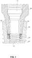
- FIG. 1showing a schematic illustration of a cross section of an implant and a prior art abutment.
- Implant 100is implanted into the patient's jaw bone.
- the implantmay or may not exceed the bone level.
- Implant 100has an opening 108, wherein the external part of the opening is shaped as a truncated cone 108.
- the lower part of the openingis a screw anchor or dowel 100'.
- a conical abutmentcomprising an abutment body 104 (for convenience referred to as “abutment”) may then be inserted into the implant, after which a screw 112 or another connecting member can be inserted and screwed into screw anchor 100' of the implant.
- the crown of one or more teethcan be inserted into the main column area 112' of the screw.
- Conical abutment 104may be designed with a slope shaped to fit opening 108 of implant 100.
- the implant external surfaceis often made rough, so as to assist the bone healing and intertwining with the implant
- the rough surfacemay also prove as an ideal platform for bacterial growth. Combined with a potential gap between the abutment and the implant, this may cause serious problems down the road.
- the conical contact area between the implant and the abutmentgives the physician control over how deep to insert the abutment into the implant.
- the physiciancan make sure that the abutment is inserted to the required depth into the implant. Correctly fitting the abutment into the implant provides for tight contact, thus eliminating undesired gaps between the abutment and the implant.
- the screwing devicemay not be calibrated precisely enough and may not show the actual torque applied, resulting in under screwing the abutment and thus weakening the contact between the implant and the abutment and creating gaps.
- the abutmentmay be over screwed into the implant, thus activating excess forces and weakening the implant,
- the abutmentmay not be initially placed in a perfectly horizontal position and may thus be inserted at an angle to the required direction, which may also create undesired gaps.
- the physiciansince the process is performed inside the person's gums, the physician has no visual feedback of the insertion, and has no way of verifying that the abutment is inserted correctly, is at the correct depth, and is leveled.
- an abutment with a substantially horizontal radial mark on the external part of the abutmentmay be located such that when the abutment is inserted correctly, the mark is at the same level as the opening of the implant.
- the openingmay refer to the top rim of the implant when installing implants in the lower jaw and the bottom rim of the implant when installing implants in the upper jaw.
- the markis made such that it is visible in a frontal image of the patient's mouth area. For example, if the area is imaged with an X-ray imaging device, is made of another material attached to the abutment, wherein the other material seems different from the abutment material in an X-ray image.
- the markmay be engraved on the external part of the abutment.
- the markmay be shaped as a radial line or strip surrounding the abutment at the required height, a dashed line, a wave or zigzag shaped engraving, or the like. If the imaging equipment is color sensitive, the mark may be made to appear in different color, or in any other manner that will show the mark in the image.
- the markmay be radial and may wrap the abutment, while in other embodiments it may be marked only on parts of the perimeter of the abutment.
- the physiciancan be careful with the amount of force applied when screwing the screw connecting the abutment to the implant.
- the physicianmay then take an image, and check whether the mark is at the same level as the opening of the implant. If it is, then the abutment is inserted correctly. If the mark is higher than the external rim of the implant (in the case of lower jaw implant), the physician may tighten the screw so that the abutment penetrates deeper into the implant. If the mark appears deeper into the jaw than the implant, then the physician may release the screw so as to avoid breaking the implant
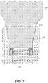
- Abutment 104provides for inserting a screw 112 having a main column 1 12' (not shown).
- Abutment 104has thereon a radial or substantially radial mark, such as band mark 200 made of a strip of a different material than abutment 104, continuous line mark 204 which may in non-claimed examples be implemented as engraving on abutment 104, zigzag line 208, dashed line 212, or the like.
- the markmay be made of any structure or material, as long as it is visible in an image taken by available imaging equipment, such as an x-ray image. It will be appreciated that if the mark is made of different material, it should be adjusted into the abutment so that no gaps are formed therebetween.
- Such materialsmay include any radio-opaque material which can be applied to titanium.
- FIG. 3showing a schematic illustration of a frontal view of an implant and a properly inserted abutment
- Fig. 3shows implant 100, abutment 104 and screw 112, wherein abutment 104 comprises radial mark 212.
- the physicianmay then take a frontal image of the relevant teeth, for example using an imaging device. If the abutment is inserted as required, the mark will appear at the correct level, for example it may be on the same level as the opening of the implant.
- the crownmay be positioned on the screw.
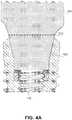
- FIG. 4Ashowing a schematic illustration of a frontal image of an implant and an improperly inserted abutment.
- abutment 104 and screw 112are inserted into implant 100.
- the abutmentwas not inserted deep enough or screw 112 was not screwed enough, such that mark 212 is external to the opening of the implant.
- the installing physicianmay further screw in screw 112, such that the abutment is inserted deeper, until mark 212 is aligned with the opening of the implant.
- FIG. 4Bshows another schematic illustration of a frontal image of an implant and an improperly inserted abutment.
- abutment 100 and screw 104is inserted into implant 100, but rather in an angle and not at the required perpendicular position.
- the installing physicianmay unscrew screw 104, remove the abutment, re-insert it and screw in screw 104 properly.
- FIG. 5showing a flowchart of steps in a method for installing an abutment
- a physician or anther dental caregivermay install an abutment into an implant placed in a patient's jaw and screw in a screw 112 to connect abutment 104 to implant 100.
- the abutmenthas thereon a radial mark or a radial addition made of another pattern or material, such that it is distinguishable from the rest of the abutment.
- the physicianmay receive an image of the implant and the abutment.
- the imagemay be an X-ray or another image.
- the imageshould be a frontal image, showing the external part of the abutment.
- step 508it is determined whether the radial mark is aligned with a predetermined level on the implant, such as the opening of the implant, or a line, a mark or an addition located on the external part of the implant.
- step 512the abutment position is accepted and the caregiver may proceed. Otherwise, on step 516 the caregiver may unscrew the screw, optionally remove the abutment, and restart inserting again on step 500, whether with the same abutment or screw or with different ones.
- the implantmay also comprise one or more substantially horizontal marks, and the abutment should be inserted such that the mark on the abutment's wrapping member 104 is aligned with the mark on the implant, rather than with the external part of the opening of the implant.
- the mark on the implantmay be radial, or may be only on the side of the implant which faces forward when installed in the patient's jaw.
Landscapes
- Health & Medical Sciences (AREA)
- Life Sciences & Earth Sciences (AREA)
- Oral & Maxillofacial Surgery (AREA)
- Dentistry (AREA)
- Animal Behavior & Ethology (AREA)
- General Health & Medical Sciences (AREA)
- Public Health (AREA)
- Veterinary Medicine (AREA)
- Orthopedic Medicine & Surgery (AREA)
- Epidemiology (AREA)
- Medical Informatics (AREA)
- Engineering & Computer Science (AREA)
- Biophysics (AREA)
- High Energy & Nuclear Physics (AREA)
- Physics & Mathematics (AREA)
- Nuclear Medicine, Radiotherapy & Molecular Imaging (AREA)
- Optics & Photonics (AREA)
- Pathology (AREA)
- Radiology & Medical Imaging (AREA)
- Biomedical Technology (AREA)
- Heart & Thoracic Surgery (AREA)
- Molecular Biology (AREA)
- Surgery (AREA)
- Dental Prosthetics (AREA)
Description
- The present disclosure relates to dentistry in general, and to a dental device assembly.
- A dental implant is a device used in dentistry to support restorations, wherein the restorations resemble a tooth or group of teeth that replace missing teeth.
- Most dental implants used today are formed similarly to an actual tooth root, and are sometimes referred to as having a "root-form". An implant is placed within the bone of the jaw, which then undergoes osseointegration with the implant. Osseointegration refers to the fusion of the implant surface with the surrounding bone.
- Dental implants can be used to support one or more dental prostheses, including crowns, implant-supported bridges or dentures.
- Once the implant is fixed within the patient's jaw bone, the process may continue with placing an abutment within the implant, upon which the crown, which comprises the visible part of the tooth or multiple teeth, may be installed. Thus, the abutment connects the implant to the crown and provides stability for the dental prosthetic.
- The bottom part of the abutment is shaped so as to be inserted tightly into the implant, and its top part is shaped to receive the crown.
- In recent years, implants having conical openings and corresponding conical abutments have gained increased popularity. In such configurations, the abutment comprises a screw and the implant may comprise a dowel, for connecting to each other.
- A major factor in the quality of the prosthesis is the exact direction, strength and stability of the connection between the implant and the abutment. It is thus required to ensure that this connection is made in the correct angle and as strong and stable as possible, but not too strong to damage the implant.
- According to an aspect of the present invention, there is provided a dental device assembly as specified in claim 1.
- The disclosure herein comprises a device, comprising: an abutment body comprising a substantially radial mark on its external part, the abutment body adapted to be connected to an implant by a connecting member, wherein the substantially radial mark is distinguishable from the abutment body in an image taken by an imaging device when the implant and abutment are installed. Within the dental device, the radial mark comprises a band made of a different material than the wrapper member. Within the dental device, the line of the implant is a level of an opening in the implant. Within the dental device, the line of the implant is optionally a substantially horizontal mark on an external part of the implant. Within the dental device, the imaging device is optionally an X-ray imager. Within the dental device, the dental abutment is a conical dental abutment. Within the dental device, the connecting member is a screw.
- There is also disclosed a method for installing an abutment in a dental implant, comprising: placing an abutment comprising a substantially radial mark on its external part into an implant and connecting the abutment to the implant by a connecting member; receiving an image of the implant and abutment; determining whether the substantially radial mark is aligned with a line of the implant; and responsive to the substantially radial mark not being aligned with the line of the implant, removing the abutment. Within the method, the radial mark comprises a band made of a different material than the wrapper member. Within the method, the radial mark is aligned with a line of the implant when the dental abutment is inserted properly into the implant. Within the method, the line of the implant is a level of an opening in the implant. Within the method, the line of the implant is a level of an opening in the implant. Within the method, the line of the implant is optionally a substantially horizontal mark on an external part of the implant Within the method the imaging device is optionally an X-ray imager. Within the method the dental abutment is a conical dental abutment. Within the method, the connecting member is a screw.
- The present disclosed subject matter will be understood and appreciated more fully from the following detailed description taken in conjunction with the drawings in which corresponding or like numerals or characters indicate corresponding or like components. Unless indicated otherwise, the drawings provide exemplary embodiments or aspects of the disclosure and do not limit the scope of the disclosure. In the drawings:
Fig. 1 is a schematic illustration of a cross section of an implant and a prior art conical abutment;Fig. 2 is a schematic illustration of a frontal view of an abutment, in accordance with some exemplary embodiments of the disclosed subject matter;Fig. 3 is a schematic illustration of a frontal view of an implant and properly inserted abutment, in accordance with some exemplary embodiments of the disclosed subject matter;Figs. 4A and4B are schematic illustrations of a frontal image of an implant and improperly inserted abutment, in accordance with some exemplary embodiments of the disclosed subject matter; andFig. 5 is a flowchart of steps in a method for installing an abutment, in accordance with some exemplary embodiments of the disclosed subject matter.- One technical problem dealt with by the disclosed subject matter relates to the insertion of an abutment, and in particular a conical abutment into an implant. An abutments may be described as implant cap which functions as the base of the crown, and which comprises or receive a screw that connects it to the implant. The implant is usually located in the jaw bone, and the abutment is placed into the implant. A screw, which may be supplied with the implant or separately is then screwed through the abutment into a screw holder area of the implant, and the crown is then attached to the top part of the screw.
- Conical connections between the abutment and the implant usually provide better fitting and better control of the insertion of the abutment into the implant. By slowly turning the screw, the physician can control how deep the abutment is inserted into the implant. Better fitting provides for eliminating gaps which may cause infections.
- Referring now to
Fig. 1 showing a schematic illustration of a cross section of an implant and a prior art abutment. - An
implant 100 is implanted into the patient's jaw bone. The implant may or may not exceed the bone level.Implant 100 has anopening 108, wherein the external part of the opening is shaped as atruncated cone 108. The lower part of the opening is a screw anchor or dowel 100'. - A conical abutment comprising an abutment body 104 (for convenience referred to as "abutment") may then be inserted into the implant, after which a
screw 112 or another connecting member can be inserted and screwed into screw anchor 100' of the implant. The crown of one or more teeth can be inserted into the main column area 112' of the screw. Conical abutment 104 may be designed with a slope shaped to fit opening 108 ofimplant 100.- A
screw 112 having a screw area and a main column 112' to which the crown may connect, is inserted throughabutment 104 and fits into the screw anchor 100' ofimplant 100 and screw anchor 104' ofabutment 104. - The implant external surface is often made rough, so as to assist the bone healing and intertwining with the implant However, the rough surface may also prove as an ideal platform for bacterial growth. Combined with a potential gap between the abutment and the implant, this may cause serious problems down the road.
- It will be appreciated that the conical contact area between the implant and the abutment gives the physician control over how deep to insert the abutment into the implant.
- By applying the required torque when screwing
screw 112, the physician can make sure that the abutment is inserted to the required depth into the implant. Correctly fitting the abutment into the implant provides for tight contact, thus eliminating undesired gaps between the abutment and the implant. - However, even when the physician applies the correct torque according to a device he or she is using, the screwing device may not be calibrated precisely enough and may not show the actual torque applied, resulting in under screwing the abutment and thus weakening the contact between the implant and the abutment and creating gaps. In other situations the abutment may be over screwed into the implant, thus activating excess forces and weakening the implant, In yet other situations, the abutment may not be initially placed in a perfectly horizontal position and may thus be inserted at an angle to the required direction, which may also create undesired gaps.
- Currently, since the process is performed inside the person's gums, the physician has no visual feedback of the insertion, and has no way of verifying that the abutment is inserted correctly, is at the correct depth, and is leveled.
- Thus it is required to provide an abutment and a method for verifying that the abutment is well fitted to the implant, such that it is not required to apply further torque and risk breaking the implant on one hand, but ensuring that no gap is left between the conical connections of the implant and the abutment, on the other hand.
- Therefore, there is thus provided in accordance with some embodiments of the disclosure, an abutment with a substantially horizontal radial mark on the external part of the abutment. The mark may be located such that when the abutment is inserted correctly, the mark is at the same level as the opening of the implant. The opening may refer to the top rim of the implant when installing implants in the lower jaw and the bottom rim of the implant when installing implants in the upper jaw. The mark is made such that it is visible in a frontal image of the patient's mouth area. For example, if the area is imaged with an X-ray imaging device, is made of another material attached to the abutment, wherein the other material seems different from the abutment material in an X-ray image. In other examples not claimed the mark may be engraved on the external part of the abutment. The mark may be shaped as a radial line or strip surrounding the abutment at the required height, a dashed line, a wave or zigzag shaped engraving, or the like. If the imaging equipment is color sensitive, the mark may be made to appear in different color, or in any other manner that will show the mark in the image. In some embodiments the mark may be radial and may wrap the abutment, while in other embodiments it may be marked only on parts of the perimeter of the abutment.
- Thus, the physician can be careful with the amount of force applied when screwing the screw connecting the abutment to the implant. The physician may then take an image, and check whether the mark is at the same level as the opening of the implant. If it is, then the abutment is inserted correctly. If the mark is higher than the external rim of the implant (in the case of lower jaw implant), the physician may tighten the screw so that the abutment penetrates deeper into the implant. If the mark appears deeper into the jaw than the implant, then the physician may release the screw so as to avoid breaking the implant
- Referring now to
Fig. 2 , showing a schematic illustration of a frontal view of an abutment, in accordance with some exemplary embodiments of the disclosure.Abutment 104 provides for inserting ascrew 112 having a main column 1 12' (not shown).Abutment 104 has thereon a radial or substantially radial mark, such asband mark 200 made of a strip of a different material thanabutment 104,continuous line mark 204 which may in non-claimed examples be implemented as engraving onabutment 104,zigzag line 208, dashedline 212, or the like. Thus, the mark may be made of any structure or material, as long as it is visible in an image taken by available imaging equipment, such as an x-ray image. It will be appreciated that if the mark is made of different material, it should be adjusted into the abutment so that no gaps are formed therebetween. Such materials may include any radio-opaque material which can be applied to titanium. - Referring now to
Fig. 3 , showing a schematic illustration of a frontal view of an implant and a properly inserted abutmentFig. 3 showsimplant 100,abutment 104 and screw 112, whereinabutment 104 comprisesradial mark 212. After the physician inserted the abutment into the implant and screwedscrew 112 as required, the physician may then take a frontal image of the relevant teeth, for example using an imaging device. If the abutment is inserted as required, the mark will appear at the correct level, for example it may be on the same level as the opening of the implant. - Once the abutment is inserted and the screw is screwed properly, the crown may be positioned on the screw.
- Referring now to
Fig. 4A showing a schematic illustration of a frontal image of an implant and an improperly inserted abutment. InFig. 4 A ,abutment 104 and screw 112 are inserted intoimplant 100. However, the abutment was not inserted deep enough or screw 112 was not screwed enough, such thatmark 212 is external to the opening of the implant. In this case, the installing physician may further screw inscrew 112, such that the abutment is inserted deeper, untilmark 212 is aligned with the opening of the implant. Fig. 4B shows another schematic illustration of a frontal image of an implant and an improperly inserted abutment. InFig. 4B ,abutment 100 and screw 104 is inserted intoimplant 100, but rather in an angle and not at the required perpendicular position. In this case, the installing physician may unscrewscrew 104, remove the abutment, re-insert it and screw inscrew 104 properly.- Referring now to
Fig. 5 , showing a flowchart of steps in a method for installing an abutment - On step 500 A physician or anther dental caregiver may install an abutment into an implant placed in a patient's jaw and screw in a
screw 112 to connectabutment 104 toimplant 100. The abutment has thereon a radial mark or a radial addition made of another pattern or material, such that it is distinguishable from the rest of the abutment. - On step 504, the physician may receive an image of the implant and the abutment. The image may be an X-ray or another image. The image should be a frontal image, showing the external part of the abutment.
- On
step 508, it is determined whether the radial mark is aligned with a predetermined level on the implant, such as the opening of the implant, or a line, a mark or an addition located on the external part of the implant. - If the radial mark is aligned with the predetermined radial line on the implant, then on
step 512 the abutment position is accepted and the caregiver may proceed. Otherwise, on step 516 the caregiver may unscrew the screw, optionally remove the abutment, and restart inserting again on step 500, whether with the same abutment or screw or with different ones. - It will be appreciated that in other embodiments, not claimed, the implant may also comprise one or more substantially horizontal marks, and the abutment should be inserted such that the mark on the abutment's
wrapping member 104 is aligned with the mark on the implant, rather than with the external part of the opening of the implant. The mark on the implant may be radial, or may be only on the side of the implant which faces forward when installed in the patient's jaw. - The terminology used herein is for the purpose of describing particular embodiments only and is not intended to be limiting of the disclosure. As used herein, the singular forms "a", "an" and "the" are intended to include the plural forms as well, unless the context clearly indicates otherwise. It will be further understood that the terms "comprises" and/or "comprising," when used in this specification, specify the presence of stated features, integers, steps, operations, elements, and/or components, but do not preclude the presence or addition of one or more other features, integers, steps, operations, elements, components, and/or groups thereof.
- The description of the present disclosure has been presented for purposes of illustration and description, but is not intended to be exhaustive or limited to the disclosure in the form disclosed. Many modifications and variations will be apparent to those of ordinary skill in the art without departing from the scope of the claims. The embodiment was chosen and described in order to best explain the principles of the disclosure and the practical application, and to enable others of ordinary skill in the art to understand the disclosure for various embodiments with various modifications as are suited to the particular use contemplated.
Claims (4)
- A dental device assembly, comprising:an implant (100) having an opening (108),a conical abutment body (104) comprising a substantially radial mark (200) on its external part, the conical abutment body (104) adapted to be connected by a conical connection to the implant (100) by a screw (112),wherein the substantially radial mark (200) is in the form of a band (200) made of a different material from the conical abutment body (104) and is distinguishable from the conical abutment body (104) in an image taken by an imaging device when the implant (100) and abutment body (104) are installed, andwherein the band (200) is located at an outer surface of a slope-shaped portion of the abutment body (104) and such that the band (200) is at the same level as the opening (108) of the implant (100) when the conical abutment body (104) is inserted correctly,
wherein the band (200) indicates alignment of the abutment body (104) relative to the implant (100). - The dental device assembly of Claim 1, wherein the band (200) made of a different colour than the abutment body.
- The dental device assembly of Claim 1, wherein the band (200) is made of a radio-opaque material.
- An dental device assembly according to claim 1, including a screw (112) insertable through the abutment body (104).
Applications Claiming Priority (2)
| Application Number | Priority Date | Filing Date | Title |
|---|---|---|---|
| IL230438AIL230438A (en) | 2014-01-13 | 2014-01-13 | Conical connection abutment for a dental implant |
| PCT/IL2015/050042WO2015104714A1 (en) | 2014-01-13 | 2015-01-12 | A conical connection for a dental implant |
Publications (3)
| Publication Number | Publication Date |
|---|---|
| EP3094282A1 EP3094282A1 (en) | 2016-11-23 |
| EP3094282A4 EP3094282A4 (en) | 2017-09-13 |
| EP3094282B1true EP3094282B1 (en) | 2020-05-27 |
Family
ID=50436488
Family Applications (1)
| Application Number | Title | Priority Date | Filing Date |
|---|---|---|---|
| EP15734984.6AActiveEP3094282B1 (en) | 2014-01-13 | 2015-01-12 | A conical connection for a dental implant |
Country Status (4)
| Country | Link |
|---|---|
| US (1) | US10524884B2 (en) |
| EP (1) | EP3094282B1 (en) |
| IL (1) | IL230438A (en) |
| WO (1) | WO2015104714A1 (en) |
Families Citing this family (2)
| Publication number | Priority date | Publication date | Assignee | Title |
|---|---|---|---|---|
| EA026399B1 (en)* | 2016-08-04 | 2017-04-28 | Мехрибон Шамсиевич Султанов | Damping dental implant |
| WO2022246736A1 (en)* | 2021-05-27 | 2022-12-01 | 何志忠 | Locking taper type strut |
Citations (1)
| Publication number | Priority date | Publication date | Assignee | Title |
|---|---|---|---|---|
| WO2015090280A1 (en)* | 2013-12-17 | 2015-06-25 | Epiphanostics GmbH | Enossal single tooth implant |
Family Cites Families (30)
| Publication number | Priority date | Publication date | Assignee | Title |
|---|---|---|---|---|
| DE3602721A1 (en) | 1986-01-30 | 1987-08-20 | Feldmuehle Ag | IMPLANT |
| US5208845A (en) | 1992-02-04 | 1993-05-04 | Gelb David A | Radiographic depth gauge |
| US5538424A (en) | 1994-05-18 | 1996-07-23 | Gelb; David A. | Radiographic depth and prosthetic positioning guide |
| US5685714A (en)* | 1994-06-16 | 1997-11-11 | Implant Innovations, Inc. | Support post for use in dental implant system |
| US5927979A (en)* | 1994-12-15 | 1999-07-27 | Biohorizons Implants Systems, Inc. | Abutment-mount system for dental implants |
| US5622499A (en) | 1995-04-10 | 1997-04-22 | Simmons; William E. | Method of manufacturing a dental abutment |
| US6068480A (en) | 1996-07-18 | 2000-05-30 | Biohorizons Implant Systems, Inc. | Abutment-mount with square driving surface |
| US6790040B2 (en)* | 1999-11-10 | 2004-09-14 | Implant Innovations, Inc. | Healing components for use in taking impressions and methods for making the same |
| CA2353051A1 (en) | 2001-07-12 | 2003-01-12 | Innova Corp. | Implant for use in aesthetic regions of the mouth |
| US7204692B2 (en) | 2002-03-13 | 2007-04-17 | Lifecore Biomedical, Inc. | Impression cap |
| US7163398B2 (en) | 2002-03-13 | 2007-01-16 | Lifecore Biomedical, Inc. | Impression cap |
| ITFI20040013A1 (en)* | 2004-01-19 | 2004-04-19 | Leone Spa | DENTAL IMPLANT |
| EP1809201A1 (en)* | 2004-09-23 | 2007-07-25 | L P M Dental Development Ltd. | Temporary dental prosthesis |
| DE102005008273A1 (en)* | 2005-02-22 | 2006-08-24 | Mundorf, Sönke, Dr. | Tooth implant comprises a bone anchoring part having an outer surface for anchoring in the jawbone and formed as a tissue anchoring part and a tooth alignment part fixed to the bone anchoring part on which a crown is fixed |
| DK2119414T3 (en)* | 2005-06-03 | 2013-05-27 | Straumann Holding Ag | Connection to multiple implant dental implant system |
| US8277218B2 (en)* | 2005-10-20 | 2012-10-02 | D Alise David D | Screw-type dental implant |
| US7806692B2 (en) | 2006-12-22 | 2010-10-05 | Implant Ingenuity Inc. | Implant abutment clips |
| US8771285B2 (en) | 2006-09-15 | 2014-07-08 | Zimmer Dental, Inc. | Drive tool for orthopedic screws |
| EP2060240A3 (en) | 2007-11-16 | 2009-08-12 | Biomet 3i, LLC | Components for use with a surgical guide for dental implant placement |
| KR100995836B1 (en) | 2008-07-24 | 2010-11-23 | 박병활 | Implant device |
| EP2347729A1 (en)* | 2010-01-21 | 2011-07-27 | Camlog Biotechnologies AG | Dental implant, abutment for a dental implant, combination of the same and an implantation set |
| US20110229850A1 (en) | 2010-03-18 | 2011-09-22 | Bretton Joseph N | Dental coping and assembly with aligning anti-rotation feature |
| EP2436336B1 (en)* | 2010-09-29 | 2016-03-16 | Ivoclar Vivadent AG | Dental implant system |
| WO2012066524A1 (en) | 2010-11-18 | 2012-05-24 | Ilya Mushayev | Set of dental implant aligning tools |
| US9283057B2 (en)* | 2011-02-02 | 2016-03-15 | Mid Corp. | System, apparatus and method for implementing implants |
| US8858228B2 (en) | 2011-03-28 | 2014-10-14 | Howard Ian Katz | Method and kit for dental implant drilling guides |
| US8944816B2 (en)* | 2011-05-16 | 2015-02-03 | Biomet 3I, Llc | Temporary abutment with combination of scanning features and provisionalization features |
| EP2736446B1 (en) | 2011-07-27 | 2020-09-02 | Abracadabra Implants Ltd | Assembly for prosthodontic restoration |
| WO2013106542A1 (en)* | 2012-01-10 | 2013-07-18 | Blaisdell Mark H | Customizable sculptable anatomical healing caps, pontics, systems, and related methods |
| US9452032B2 (en)* | 2012-01-23 | 2016-09-27 | Biomet 3I, Llc | Soft tissue preservation temporary (shell) immediate-implant abutment with biological active surface |
- 2014
- 2014-01-13ILIL230438Apatent/IL230438A/enactiveIP Right Grant
- 2015
- 2015-01-12EPEP15734984.6Apatent/EP3094282B1/enactiveActive
- 2015-01-12WOPCT/IL2015/050042patent/WO2015104714A1/enactiveApplication Filing
- 2015-01-12USUS15/110,744patent/US10524884B2/ennot_activeExpired - Fee Related
Patent Citations (1)
| Publication number | Priority date | Publication date | Assignee | Title |
|---|---|---|---|---|
| WO2015090280A1 (en)* | 2013-12-17 | 2015-06-25 | Epiphanostics GmbH | Enossal single tooth implant |
Also Published As
| Publication number | Publication date |
|---|---|
| IL230438A0 (en) | 2014-03-31 |
| WO2015104714A1 (en) | 2015-07-16 |
| EP3094282A4 (en) | 2017-09-13 |
| US10524884B2 (en) | 2020-01-07 |
| EP3094282A1 (en) | 2016-11-23 |
| IL230438A (en) | 2015-07-30 |
| US20160317252A1 (en) | 2016-11-03 |
Similar Documents
| Publication | Publication Date | Title |
|---|---|---|
| EP3335667B1 (en) | Dental implant | |
| KR101638558B1 (en) | digital onebody abutment for dental implant using digital library | |
| US20030082499A1 (en) | Components and method for improved impression making | |
| KR101539089B1 (en) | Dental prosthesis method using 3d printer | |
| US20090317769A1 (en) | Resilient coping for immediate loading of dental implants | |
| US5897320A (en) | Hydrostatic pressure relieved abutment post | |
| NZ554216A (en) | Temporary dental prosthesis | |
| JP2008541858A (en) | Locking cap for dental implant | |
| JPH0457344B2 (en) | ||
| EP3021784B1 (en) | Connection device for dental implants | |
| US20240148476A1 (en) | Dental Prosthesis | |
| EP3094282B1 (en) | A conical connection for a dental implant | |
| KR101673379B1 (en) | Dental implant | |
| JP5553293B1 (en) | Dental implant | |
| CA2887429A1 (en) | A cradle for positioning a final dental prosthesis, a system incorporating the cradle and a method of using the same | |
| KR20070104661A (en) | Dental prosthesis and method of provision | |
| KR102125419B1 (en) | customized dental implant for immediate implanting after extraction of tooth | |
| KR102080243B1 (en) | general purpose splint for measuring occlusal vertical dimention | |
| CN110099650B (en) | Artificial tooth | |
| KR101592395B1 (en) | Method for making custom abutment | |
| KR20140113895A (en) | Dental implant system | |
| KR101296740B1 (en) | Non-submerged typed abutment for implant | |
| KR101928738B1 (en) | Protective instrument for stability of individualized tooth replicated implant | |
| KR101435551B1 (en) | Separated type healing abutment | |
| KR20160041606A (en) | Implant |
Legal Events
| Date | Code | Title | Description |
|---|---|---|---|
| PUAI | Public reference made under article 153(3) epc to a published international application that has entered the european phase | Free format text:ORIGINAL CODE: 0009012 | |
| 17P | Request for examination filed | Effective date:20160711 | |
| AK | Designated contracting states | Kind code of ref document:A1 Designated state(s):AL AT BE BG CH CY CZ DE DK EE ES FI FR GB GR HR HU IE IS IT LI LT LU LV MC MK MT NL NO PL PT RO RS SE SI SK SM TR | |
| AX | Request for extension of the european patent | Extension state:BA ME | |
| DAX | Request for extension of the european patent (deleted) | ||
| A4 | Supplementary search report drawn up and despatched | Effective date:20170810 | |
| RIC1 | Information provided on ipc code assigned before grant | Ipc:A61C 8/00 20060101AFI20170804BHEP Ipc:A61C 9/00 20060101ALI20170804BHEP | |
| STAA | Information on the status of an ep patent application or granted ep patent | Free format text:STATUS: EXAMINATION IS IN PROGRESS | |
| 17Q | First examination report despatched | Effective date:20180614 | |
| GRAP | Despatch of communication of intention to grant a patent | Free format text:ORIGINAL CODE: EPIDOSNIGR1 | |
| STAA | Information on the status of an ep patent application or granted ep patent | Free format text:STATUS: GRANT OF PATENT IS INTENDED | |
| INTG | Intention to grant announced | Effective date:20191219 | |
| GRAS | Grant fee paid | Free format text:ORIGINAL CODE: EPIDOSNIGR3 | |
| GRAA | (expected) grant | Free format text:ORIGINAL CODE: 0009210 | |
| STAA | Information on the status of an ep patent application or granted ep patent | Free format text:STATUS: THE PATENT HAS BEEN GRANTED | |
| AK | Designated contracting states | Kind code of ref document:B1 Designated state(s):AL AT BE BG CH CY CZ DE DK EE ES FI FR GB GR HR HU IE IS IT LI LT LU LV MC MK MT NL NO PL PT RO RS SE SI SK SM TR | |
| REG | Reference to a national code | Ref country code:GB Ref legal event code:FG4D | |
| REG | Reference to a national code | Ref country code:CH Ref legal event code:EP | |
| REG | Reference to a national code | Ref country code:AT Ref legal event code:REF Ref document number:1273729 Country of ref document:AT Kind code of ref document:T Effective date:20200615 | |
| REG | Reference to a national code | Ref country code:DE Ref legal event code:R096 Ref document number:602015053340 Country of ref document:DE | |
| REG | Reference to a national code | Ref country code:LT Ref legal event code:MG4D | |
| PG25 | Lapsed in a contracting state [announced via postgrant information from national office to epo] | Ref country code:LT Free format text:LAPSE BECAUSE OF FAILURE TO SUBMIT A TRANSLATION OF THE DESCRIPTION OR TO PAY THE FEE WITHIN THE PRESCRIBED TIME-LIMIT Effective date:20200527 Ref country code:SE Free format text:LAPSE BECAUSE OF FAILURE TO SUBMIT A TRANSLATION OF THE DESCRIPTION OR TO PAY THE FEE WITHIN THE PRESCRIBED TIME-LIMIT Effective date:20200527 Ref country code:PT Free format text:LAPSE BECAUSE OF FAILURE TO SUBMIT A TRANSLATION OF THE DESCRIPTION OR TO PAY THE FEE WITHIN THE PRESCRIBED TIME-LIMIT Effective date:20200928 Ref country code:IS Free format text:LAPSE BECAUSE OF FAILURE TO SUBMIT A TRANSLATION OF THE DESCRIPTION OR TO PAY THE FEE WITHIN THE PRESCRIBED TIME-LIMIT Effective date:20200927 Ref country code:GR Free format text:LAPSE BECAUSE OF FAILURE TO SUBMIT A TRANSLATION OF THE DESCRIPTION OR TO PAY THE FEE WITHIN THE PRESCRIBED TIME-LIMIT Effective date:20200828 Ref country code:NO Free format text:LAPSE BECAUSE OF FAILURE TO SUBMIT A TRANSLATION OF THE DESCRIPTION OR TO PAY THE FEE WITHIN THE PRESCRIBED TIME-LIMIT Effective date:20200827 Ref country code:FI Free format text:LAPSE BECAUSE OF FAILURE TO SUBMIT A TRANSLATION OF THE DESCRIPTION OR TO PAY THE FEE WITHIN THE PRESCRIBED TIME-LIMIT Effective date:20200527 | |
| REG | Reference to a national code | Ref country code:NL Ref legal event code:MP Effective date:20200527 | |
| PG25 | Lapsed in a contracting state [announced via postgrant information from national office to epo] | Ref country code:HR Free format text:LAPSE BECAUSE OF FAILURE TO SUBMIT A TRANSLATION OF THE DESCRIPTION OR TO PAY THE FEE WITHIN THE PRESCRIBED TIME-LIMIT Effective date:20200527 Ref country code:LV Free format text:LAPSE BECAUSE OF FAILURE TO SUBMIT A TRANSLATION OF THE DESCRIPTION OR TO PAY THE FEE WITHIN THE PRESCRIBED TIME-LIMIT Effective date:20200527 Ref country code:BG Free format text:LAPSE BECAUSE OF FAILURE TO SUBMIT A TRANSLATION OF THE DESCRIPTION OR TO PAY THE FEE WITHIN THE PRESCRIBED TIME-LIMIT Effective date:20200827 Ref country code:RS Free format text:LAPSE BECAUSE OF FAILURE TO SUBMIT A TRANSLATION OF THE DESCRIPTION OR TO PAY THE FEE WITHIN THE PRESCRIBED TIME-LIMIT Effective date:20200527 | |
| REG | Reference to a national code | Ref country code:AT Ref legal event code:MK05 Ref document number:1273729 Country of ref document:AT Kind code of ref document:T Effective date:20200527 | |
| PG25 | Lapsed in a contracting state [announced via postgrant information from national office to epo] | Ref country code:NL Free format text:LAPSE BECAUSE OF FAILURE TO SUBMIT A TRANSLATION OF THE DESCRIPTION OR TO PAY THE FEE WITHIN THE PRESCRIBED TIME-LIMIT Effective date:20200527 Ref country code:AL Free format text:LAPSE BECAUSE OF FAILURE TO SUBMIT A TRANSLATION OF THE DESCRIPTION OR TO PAY THE FEE WITHIN THE PRESCRIBED TIME-LIMIT Effective date:20200527 | |
| PG25 | Lapsed in a contracting state [announced via postgrant information from national office to epo] | Ref country code:CZ Free format text:LAPSE BECAUSE OF FAILURE TO SUBMIT A TRANSLATION OF THE DESCRIPTION OR TO PAY THE FEE WITHIN THE PRESCRIBED TIME-LIMIT Effective date:20200527 Ref country code:RO Free format text:LAPSE BECAUSE OF FAILURE TO SUBMIT A TRANSLATION OF THE DESCRIPTION OR TO PAY THE FEE WITHIN THE PRESCRIBED TIME-LIMIT Effective date:20200527 Ref country code:EE Free format text:LAPSE BECAUSE OF FAILURE TO SUBMIT A TRANSLATION OF THE DESCRIPTION OR TO PAY THE FEE WITHIN THE PRESCRIBED TIME-LIMIT Effective date:20200527 Ref country code:SM Free format text:LAPSE BECAUSE OF FAILURE TO SUBMIT A TRANSLATION OF THE DESCRIPTION OR TO PAY THE FEE WITHIN THE PRESCRIBED TIME-LIMIT Effective date:20200527 Ref country code:IT Free format text:LAPSE BECAUSE OF FAILURE TO SUBMIT A TRANSLATION OF THE DESCRIPTION OR TO PAY THE FEE WITHIN THE PRESCRIBED TIME-LIMIT Effective date:20200527 Ref country code:AT Free format text:LAPSE BECAUSE OF FAILURE TO SUBMIT A TRANSLATION OF THE DESCRIPTION OR TO PAY THE FEE WITHIN THE PRESCRIBED TIME-LIMIT Effective date:20200527 Ref country code:ES Free format text:LAPSE BECAUSE OF FAILURE TO SUBMIT A TRANSLATION OF THE DESCRIPTION OR TO PAY THE FEE WITHIN THE PRESCRIBED TIME-LIMIT Effective date:20200527 Ref country code:DK Free format text:LAPSE BECAUSE OF FAILURE TO SUBMIT A TRANSLATION OF THE DESCRIPTION OR TO PAY THE FEE WITHIN THE PRESCRIBED TIME-LIMIT Effective date:20200527 | |
| PG25 | Lapsed in a contracting state [announced via postgrant information from national office to epo] | Ref country code:PL Free format text:LAPSE BECAUSE OF FAILURE TO SUBMIT A TRANSLATION OF THE DESCRIPTION OR TO PAY THE FEE WITHIN THE PRESCRIBED TIME-LIMIT Effective date:20200527 Ref country code:SK Free format text:LAPSE BECAUSE OF FAILURE TO SUBMIT A TRANSLATION OF THE DESCRIPTION OR TO PAY THE FEE WITHIN THE PRESCRIBED TIME-LIMIT Effective date:20200527 | |
| REG | Reference to a national code | Ref country code:DE Ref legal event code:R097 Ref document number:602015053340 Country of ref document:DE | |
| PLBE | No opposition filed within time limit | Free format text:ORIGINAL CODE: 0009261 | |
| STAA | Information on the status of an ep patent application or granted ep patent | Free format text:STATUS: NO OPPOSITION FILED WITHIN TIME LIMIT | |
| 26N | No opposition filed | Effective date:20210302 | |
| PG25 | Lapsed in a contracting state [announced via postgrant information from national office to epo] | Ref country code:SI Free format text:LAPSE BECAUSE OF FAILURE TO SUBMIT A TRANSLATION OF THE DESCRIPTION OR TO PAY THE FEE WITHIN THE PRESCRIBED TIME-LIMIT Effective date:20200527 | |
| PG25 | Lapsed in a contracting state [announced via postgrant information from national office to epo] | Ref country code:MC Free format text:LAPSE BECAUSE OF FAILURE TO SUBMIT A TRANSLATION OF THE DESCRIPTION OR TO PAY THE FEE WITHIN THE PRESCRIBED TIME-LIMIT Effective date:20200527 | |
| REG | Reference to a national code | Ref country code:CH Ref legal event code:PL | |
| GBPC | Gb: european patent ceased through non-payment of renewal fee | Effective date:20210112 | |
| PG25 | Lapsed in a contracting state [announced via postgrant information from national office to epo] | Ref country code:LU Free format text:LAPSE BECAUSE OF NON-PAYMENT OF DUE FEES Effective date:20210112 | |
| REG | Reference to a national code | Ref country code:BE Ref legal event code:MM Effective date:20210131 | |
| PG25 | Lapsed in a contracting state [announced via postgrant information from national office to epo] | Ref country code:FR Free format text:LAPSE BECAUSE OF NON-PAYMENT OF DUE FEES Effective date:20210131 | |
| PG25 | Lapsed in a contracting state [announced via postgrant information from national office to epo] | Ref country code:GB Free format text:LAPSE BECAUSE OF NON-PAYMENT OF DUE FEES Effective date:20210112 Ref country code:LI Free format text:LAPSE BECAUSE OF NON-PAYMENT OF DUE FEES Effective date:20210131 Ref country code:CH Free format text:LAPSE BECAUSE OF NON-PAYMENT OF DUE FEES Effective date:20210131 | |
| PG25 | Lapsed in a contracting state [announced via postgrant information from national office to epo] | Ref country code:IE Free format text:LAPSE BECAUSE OF NON-PAYMENT OF DUE FEES Effective date:20210112 | |
| PGFP | Annual fee paid to national office [announced via postgrant information from national office to epo] | Ref country code:DE Payment date:20220120 Year of fee payment:8 | |
| PG25 | Lapsed in a contracting state [announced via postgrant information from national office to epo] | Ref country code:BE Free format text:LAPSE BECAUSE OF NON-PAYMENT OF DUE FEES Effective date:20210131 | |
| PG25 | Lapsed in a contracting state [announced via postgrant information from national office to epo] | Ref country code:HU Free format text:LAPSE BECAUSE OF FAILURE TO SUBMIT A TRANSLATION OF THE DESCRIPTION OR TO PAY THE FEE WITHIN THE PRESCRIBED TIME-LIMIT; INVALID AB INITIO Effective date:20150112 | |
| PG25 | Lapsed in a contracting state [announced via postgrant information from national office to epo] | Ref country code:CY Free format text:LAPSE BECAUSE OF FAILURE TO SUBMIT A TRANSLATION OF THE DESCRIPTION OR TO PAY THE FEE WITHIN THE PRESCRIBED TIME-LIMIT Effective date:20200527 | |
| REG | Reference to a national code | Ref country code:DE Ref legal event code:R119 Ref document number:602015053340 Country of ref document:DE | |
| PG25 | Lapsed in a contracting state [announced via postgrant information from national office to epo] | Ref country code:DE Free format text:LAPSE BECAUSE OF NON-PAYMENT OF DUE FEES Effective date:20230801 | |
| PG25 | Lapsed in a contracting state [announced via postgrant information from national office to epo] | Ref country code:MK Free format text:LAPSE BECAUSE OF FAILURE TO SUBMIT A TRANSLATION OF THE DESCRIPTION OR TO PAY THE FEE WITHIN THE PRESCRIBED TIME-LIMIT Effective date:20200527 | |
| PG25 | Lapsed in a contracting state [announced via postgrant information from national office to epo] | Ref country code:MT Free format text:LAPSE BECAUSE OF FAILURE TO SUBMIT A TRANSLATION OF THE DESCRIPTION OR TO PAY THE FEE WITHIN THE PRESCRIBED TIME-LIMIT Effective date:20200527 |