EP3094241B1 - Systems and methods for evaluating hemodialysis arteriovenous fistula maturation - Google Patents
Systems and methods for evaluating hemodialysis arteriovenous fistula maturationDownload PDFInfo
- Publication number
- EP3094241B1 EP3094241B1EP15704866.1AEP15704866AEP3094241B1EP 3094241 B1EP3094241 B1EP 3094241B1EP 15704866 AEP15704866 AEP 15704866AEP 3094241 B1EP3094241 B1EP 3094241B1
- Authority
- EP
- European Patent Office
- Prior art keywords
- guidewire
- fistula
- sensor
- flow
- computer
- Prior art date
- Legal status (The legal status is an assumption and is not a legal conclusion. Google has not performed a legal analysis and makes no representation as to the accuracy of the status listed.)
- Active
Links
Images


Classifications
- A—HUMAN NECESSITIES
- A61—MEDICAL OR VETERINARY SCIENCE; HYGIENE
- A61B—DIAGNOSIS; SURGERY; IDENTIFICATION
- A61B5/00—Measuring for diagnostic purposes; Identification of persons
- A61B5/68—Arrangements of detecting, measuring or recording means, e.g. sensors, in relation to patient
- A61B5/6846—Arrangements of detecting, measuring or recording means, e.g. sensors, in relation to patient specially adapted to be brought in contact with an internal body part, i.e. invasive
- A61B5/6847—Arrangements of detecting, measuring or recording means, e.g. sensors, in relation to patient specially adapted to be brought in contact with an internal body part, i.e. invasive mounted on an invasive device
- A61B5/6851—Guide wires
- A—HUMAN NECESSITIES
- A61—MEDICAL OR VETERINARY SCIENCE; HYGIENE
- A61B—DIAGNOSIS; SURGERY; IDENTIFICATION
- A61B5/00—Measuring for diagnostic purposes; Identification of persons
- A61B5/02—Detecting, measuring or recording for evaluating the cardiovascular system, e.g. pulse, heart rate, blood pressure or blood flow
- A61B5/021—Measuring pressure in heart or blood vessels
- A61B5/0215—Measuring pressure in heart or blood vessels by means inserted into the body
- A61B5/02158—Measuring pressure in heart or blood vessels by means inserted into the body provided with two or more sensor elements
- A—HUMAN NECESSITIES
- A61—MEDICAL OR VETERINARY SCIENCE; HYGIENE
- A61B—DIAGNOSIS; SURGERY; IDENTIFICATION
- A61B5/00—Measuring for diagnostic purposes; Identification of persons
- A61B5/02—Detecting, measuring or recording for evaluating the cardiovascular system, e.g. pulse, heart rate, blood pressure or blood flow
- A61B5/026—Measuring blood flow
- A61B5/0265—Measuring blood flow using electromagnetic means, e.g. electromagnetic flowmeter
- A—HUMAN NECESSITIES
- A61—MEDICAL OR VETERINARY SCIENCE; HYGIENE
- A61B—DIAGNOSIS; SURGERY; IDENTIFICATION
- A61B8/00—Diagnosis using ultrasonic, sonic or infrasonic waves
- A61B8/06—Measuring blood flow
- A—HUMAN NECESSITIES
- A61—MEDICAL OR VETERINARY SCIENCE; HYGIENE
- A61B—DIAGNOSIS; SURGERY; IDENTIFICATION
- A61B8/00—Diagnosis using ultrasonic, sonic or infrasonic waves
- A61B8/08—Clinical applications
- A61B8/0891—Clinical applications for diagnosis of blood vessels
- A—HUMAN NECESSITIES
- A61—MEDICAL OR VETERINARY SCIENCE; HYGIENE
- A61B—DIAGNOSIS; SURGERY; IDENTIFICATION
- A61B8/00—Diagnosis using ultrasonic, sonic or infrasonic waves
- A61B8/12—Diagnosis using ultrasonic, sonic or infrasonic waves in body cavities or body tracts, e.g. by using catheters
- A—HUMAN NECESSITIES
- A61—MEDICAL OR VETERINARY SCIENCE; HYGIENE
- A61B—DIAGNOSIS; SURGERY; IDENTIFICATION
- A61B8/00—Diagnosis using ultrasonic, sonic or infrasonic waves
- A61B8/44—Constructional features of the ultrasonic, sonic or infrasonic diagnostic device
- A61B8/4444—Constructional features of the ultrasonic, sonic or infrasonic diagnostic device related to the probe
- A61B8/445—Details of catheter construction
- A—HUMAN NECESSITIES
- A61—MEDICAL OR VETERINARY SCIENCE; HYGIENE
- A61B—DIAGNOSIS; SURGERY; IDENTIFICATION
- A61B8/00—Diagnosis using ultrasonic, sonic or infrasonic waves
- A61B8/48—Diagnostic techniques
- A61B8/488—Diagnostic techniques involving Doppler signals
- A—HUMAN NECESSITIES
- A61—MEDICAL OR VETERINARY SCIENCE; HYGIENE
- A61M—DEVICES FOR INTRODUCING MEDIA INTO, OR ONTO, THE BODY; DEVICES FOR TRANSDUCING BODY MEDIA OR FOR TAKING MEDIA FROM THE BODY; DEVICES FOR PRODUCING OR ENDING SLEEP OR STUPOR
- A61M1/00—Suction or pumping devices for medical purposes; Devices for carrying-off, for treatment of, or for carrying-over, body-liquids; Drainage systems
- A61M1/36—Other treatment of blood in a by-pass of the natural circulatory system, e.g. temperature adaptation, irradiation ; Extra-corporeal blood circuits
- A61M1/3621—Extra-corporeal blood circuits
- A61M1/3653—Interfaces between patient blood circulation and extra-corporal blood circuit
- A61M1/3655—Arterio-venous shunts or fistulae
- A—HUMAN NECESSITIES
- A61—MEDICAL OR VETERINARY SCIENCE; HYGIENE
- A61M—DEVICES FOR INTRODUCING MEDIA INTO, OR ONTO, THE BODY; DEVICES FOR TRANSDUCING BODY MEDIA OR FOR TAKING MEDIA FROM THE BODY; DEVICES FOR PRODUCING OR ENDING SLEEP OR STUPOR
- A61M25/00—Catheters; Hollow probes
- A61M25/01—Introducing, guiding, advancing, emplacing or holding catheters
- A61M25/09—Guide wires
- A—HUMAN NECESSITIES
- A61—MEDICAL OR VETERINARY SCIENCE; HYGIENE
- A61B—DIAGNOSIS; SURGERY; IDENTIFICATION
- A61B2560/00—Constructional details of operational features of apparatus; Accessories for medical measuring apparatus
- A61B2560/04—Constructional details of apparatus
- A61B2560/0475—Special features of memory means, e.g. removable memory cards
- A—HUMAN NECESSITIES
- A61—MEDICAL OR VETERINARY SCIENCE; HYGIENE
- A61B—DIAGNOSIS; SURGERY; IDENTIFICATION
- A61B2562/00—Details of sensors; Constructional details of sensor housings or probes; Accessories for sensors
- A61B2562/02—Details of sensors specially adapted for in-vivo measurements
- A61B2562/0247—Pressure sensors
- A—HUMAN NECESSITIES
- A61—MEDICAL OR VETERINARY SCIENCE; HYGIENE
- A61M—DEVICES FOR INTRODUCING MEDIA INTO, OR ONTO, THE BODY; DEVICES FOR TRANSDUCING BODY MEDIA OR FOR TAKING MEDIA FROM THE BODY; DEVICES FOR PRODUCING OR ENDING SLEEP OR STUPOR
- A61M25/00—Catheters; Hollow probes
- A61M25/01—Introducing, guiding, advancing, emplacing or holding catheters
- A61M25/09—Guide wires
- A61M2025/09058—Basic structures of guide wires
- A61M2025/09083—Basic structures of guide wires having a coil around a core
- A—HUMAN NECESSITIES
- A61—MEDICAL OR VETERINARY SCIENCE; HYGIENE
- A61M—DEVICES FOR INTRODUCING MEDIA INTO, OR ONTO, THE BODY; DEVICES FOR TRANSDUCING BODY MEDIA OR FOR TAKING MEDIA FROM THE BODY; DEVICES FOR PRODUCING OR ENDING SLEEP OR STUPOR
- A61M25/00—Catheters; Hollow probes
- A61M25/01—Introducing, guiding, advancing, emplacing or holding catheters
- A61M25/09—Guide wires
- A61M2025/09116—Design of handles or shafts or gripping surfaces thereof for manipulating guide wires
- A—HUMAN NECESSITIES
- A61—MEDICAL OR VETERINARY SCIENCE; HYGIENE
- A61M—DEVICES FOR INTRODUCING MEDIA INTO, OR ONTO, THE BODY; DEVICES FOR TRANSDUCING BODY MEDIA OR FOR TAKING MEDIA FROM THE BODY; DEVICES FOR PRODUCING OR ENDING SLEEP OR STUPOR
- A61M25/00—Catheters; Hollow probes
- A61M25/01—Introducing, guiding, advancing, emplacing or holding catheters
- A61M25/09—Guide wires
- A61M2025/0915—Guide wires having features for changing the stiffness
- A—HUMAN NECESSITIES
- A61—MEDICAL OR VETERINARY SCIENCE; HYGIENE
- A61M—DEVICES FOR INTRODUCING MEDIA INTO, OR ONTO, THE BODY; DEVICES FOR TRANSDUCING BODY MEDIA OR FOR TAKING MEDIA FROM THE BODY; DEVICES FOR PRODUCING OR ENDING SLEEP OR STUPOR
- A61M25/00—Catheters; Hollow probes
- A61M25/01—Introducing, guiding, advancing, emplacing or holding catheters
- A61M25/09—Guide wires
- A61M2025/09175—Guide wires having specific characteristics at the distal tip
- A61M2025/09183—Guide wires having specific characteristics at the distal tip having tools at the distal tip
Definitions
- the inventionrelates to evaluation of maturity of arteriovenous (AV) fistula using guidewires that measure intravascular blood flow and/or pressure.
- AVarteriovenous
- Hemodialysisis a common method for treating kidney failures and involves flowing blood through a filter to remove wastes.
- a fistulais created that connects an artery to a vein, or optionally an AV graft is created by using a tube to connect the artery to the vein.
- a fistulaAfter creation, a fistula can take several weeks to develop enough to be used, i.e., to reach fistula maturation. Hemodialysis can be unsuccessful or lead to complications if performed before, or too long after, fistula maturation.
- the evaluation of maturation by color-flow Doppler ultrasoundhas been proposed. See, e.g., Toregeani, et al., 2008, Evaluation of hemodialysis arteriovenous fistula maturation by color-flow Doppler ultrasound, J Vasc Bras 7(3):203-213 or Ferring, et al., 2008, Vascular ultrasound for the pre-operative evaluation prior to arteriovenous fistula formation for haemodialysis: review of the evidence, Nephrol. Dial. Transplant. 23(6):1809-1815 .
- the cathetermust be swapped for a catheter that can perform the intervention (e.g., thrombectomy). Every removal and insertion of a new catheter raises risk of complications.
- the ultrasound catheteritself provides some guidance to a treatment location, it does not provide direct navigational guidance for treatment after having been removed from the body.
- medical organizationsrecommend fistula access, evaluating maturation is imperfect due to the fact that the ultrasound catheter being used to measure flow also partially impedes that flow. That is, the catheter itself partially occludes flow and interferes with obtaining an actual measurement of flow through an AV fistula.
- US 2010/0130864 A1discloses methods and systems for detecting a maturing arteriovenous fistula.
- a circumferential vessel wall stressis determined from the measured blood pressure, the wall thickness of the fistula and a determined radius of the measured diameter of the fistula.
- the determined circumferential vessel stressis compared to a predetermined threshold stress to determine if the fistula is mature.
- US 2011/0060229 A1discloses methods and structures for detecting a physiologic parameter of a target anatomical sites for stenotic lesions in grafts and fistulas created for dialysis.
- a detection devicecan be used to invasively measure the pressure in these grafts of fistulas (in order to assess their patency and determine whether more expensive tests (e.g. angiography) or procedures (e.g. angioplasty) are warranted.
- the inventionprovides systems for evaluating AV fistula maturation using an instrumented guidewire to measure intravascular blood flow and/or pressure.
- an accurate measurementcan be made that is useful for identifying when a fistula is mature and therefore ready to be used for hemodialysis.
- the guidewirecan be instrumented to measure flow velocity, pressure, other properties, or a combination thereof.
- the guidewirecan be operated with a system computer that uses the measurement to provide information that aids in evaluating maturity. Fistula maturation is correctly identified, allowing hemodialysis to be initiated at a suitable time, avoiding complications. This lowers cost of hemodialysis while improving results, leading to greater patient health.
- the same guidewirecan be used to guide a catheter to a location proximal to where the measurement is made.
- the guidewirecan be used to guide delivery of the therapy via a catheter, without the need for a catheter exchange, thus decreasing complications associated with catheter exchanges.
- Assessing maturation of a fistulaincludes inserting an instrumented guidewire into a vessel of a patent, according to the disclosure.
- the vesselis in communication with a fistula, which provides fluid communication between the vessel and an adjacent vessel.
- a fistulawhich provides fluid communication between the vessel and an adjacent vessel.
- an arteriovenous fistula for hemodialysismay be assessed.
- the flow of blood through the fistulais measured using the guidewire and the measured flow of blood is used to determine if the fistula is mature.
- Measuring the flow of bloodmay include collecting data with a sensing device on the guidewire while the guidewire is within the vessel and relaying the data to a computer.
- the computerdetermines an observed rate of the flow of blood.
- a computer programis used to provide information about the maturity of the fistula based on the observed rate of blood flow. Determining maturation may be done by comparing the observed rate to a standard. For example, an observed rate of 600 mL/ min or greater may indicate that the fistula is mature.
- the instrumented guidewiremay include an ultrasonic transducer (e.g., for Doppler velocity), a pressure sensor, other sensors, or a combination thereof.
- the guidewiremay be specially designed for arteriovenous hemodialysis fistula.
- the guidewiremay be shorter than other intravascular guidewires, stiffer, or both.
- the guidewiremay have a diameter of about 0.035 inches or less.
- the guidewireis less than about 110 cm long, and preferably less than about 80 cm long (e.g., about 50 to 60 cm long).
- the guidewirecan include a stiffening material to give it a desires flexural modulus (e.g., at least about 15 GPa, or at least about 50 GPa).
- the guidewirewill have a stiffness of 100 GPa flexural modulus or greater.
- the method according to the disclosurefurther includes sliding a catheter over the guidewire and using the catheter over the guidewire to deliver therapy to the fistula.
- the systemincludes a sensing guidewire comprising a sensor and configured to be inserted into a vessel of a patient, wherein the vessel comprises a fistula providing fluid communication between the vessel and an adjacent vessel, and a computer communicatively linked with the sensing guidewire.
- the computerreceives a measurement from the sensor, uses the measurement to determine an observed rate of blood flow through a fistula, and uses the determined observed rate of blood flow for determining if the fistula is mature.
- the systemoptionally can include a catheter to deliver therapy to the fistula.
- the computerincludes a program in memory that causes the computer to provide information about the maturity of the fistula based on the observed rate of blood flow.
- a guidewire of the inventioncan include a pressure sensor, a flow sensor, a temperature sensor or combinations thereof.
- the guidewireis a combination guidewire that includes both a pressure sensor and a flow sensor.
- Pressure sensorscan be used to measure pressure within the lumen and flow sensors can be used to measure the velocity of blood flow.
- Temperature sensorscan measure the temperature of a lumen.
- a guidewire with both a pressure sensor and a flow sensorprovides a desirable environment in which to calculate fractional flow reserve (FFR) using pressure readings, and coronary flow reserve (CFR), or non-coronary vessel flow reserve, using flow readings.
- FFRfractional flow reserve
- CFRcoronary flow reserve
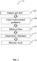
- FIG. 1diagrams a method 101 of using a functional management wire (FM wire) to assess maturation of AV fistulas or grafts.
- FM wirefunctional management wire
- Use of a wireresults in less vessel obstruction than a catheter and offers the ability to intervene over the FM wire at the time of the procedure.
- An FM wirecould provide flow measurements, pressure measurements, others, or a combination thereof.
- Functional managementis a guide wire based technology that analyzes pressure, flow, or both from the inside of a vessel.
- the wireprovides a simple, reproducible measurement, and may be used in conjunction with angiography.
- Method 101starts 105 with a patient with an AV fistula.
- An instrumented guidewireis inserted 109 into the appropriate vessel to make measurements proximal (e.g., at or near) the AV fistula.
- the guidewireis inserted 109 into the vein immediately downstream of the fistula.
- measurementsare made where flow is laminar. Measurements may be made following generally procedure described in Robbin, et al., 2002, Hemodialysis arteriovenous fistula maturity: US evaluation, Radiology 225(1):59-64 .
- the flow of blood through the fistula or graftis measured 117.
- the observed flow is bloodis compared 121 to a standard (e.g., for a binary yes/no call, or to stratify). This can be done using a computer that receives data from the guidewire.
- the computercan further provide 127 a result supporting a determination of whether the fistula is mature.
- Any suitable instrumented guidewirecan be used to measure 117 the blood flow.
- a functional management guidewirecan be used.
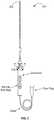
- FIG. 2illustrates a guidewire 201 with a pressure sensor 204.
- Guidewire 201generally defines an elongated body extending from a proximal end 210 to a distal end 202.
- Proximal end 210connects to connector housing 215, which offers a modular plug 221 for connection to a computing device in systems of the invention.
- a pressure sensorallows one to obtain pressure measurements within a body lumen.
- pressure sensorsallow one to measure of fractional flow reserve (FFR) in vessel, which is a comparison of the pressure within a vessel at positions prior to the fistula and after the fistula.
- FFRfractional flow reserve
- the level of FFRdetermines the patency of the fistula, which allows physicians to more accurately identify fistula maturation. For example, an FFR measurement above 0.80 may indicate maturation.
- FFRfractional flow reserve
- Another benefitis that a physician can measure the pressure before and after an intraluminal intervention procedure to determine the impact of the procedure.
- Pressure sensor 204can be mounted on the distal portion of a flexible elongate member.
- the pressure sensoris positioned distal to the compressible and bendable coil segment of the elongate member. This allows the pressure sensor to move away from the longitudinal axis and coil segment as bended.
- the pressure sensorcan be formed of a crystal semiconductor material having a recess therein and forming a diaphragm bordered by a rim.
- a reinforcing memberis bonded to the crystal and reinforces the rim of the crystal and has a cavity therein underlying the diaphragm and exposed to the diaphragm.
- a resistor having opposite endsis carried by the crystal and has a portion thereof overlying a portion of the diaphragm.
- a guidewirecan include a flow sensor.
- a guidewireis used that includes a flow sensor.
- a suitable product for guidewire 201is the PrimeWire PRESTIGE from Volcano Corporation.
- the guide wire of the present inventionis comprised of a flexible elongate element having proximal and distal ends and a diameter of 0.018" and less as disclosed in U.S. Pat. No. 5,125,137 , U.S. Pat. No. 5,163,445 , U.S. Pat. No. 5,174,295 , U.S. Pat. No. 5,178,159 , U.S. Pat. No. 5,226,421 , U.S. Pat. No. 5,240,437 and U.S. Pat. No. 6,106,476 .
- a guidewire of the inventionmay include a flexible elongate element having proximal and distal extremities, and can be formed of a suitable material such as stainless steel, Nitinol, polyimide, PEEK or other metallic or polymeric materials having an outside diameter for example of 0.018" or less and having a suitable wall thickness, such as, e.g., 0.001" to 0.002".
- This flexible elongate elementis conventionally called a hypotube.
- the hypotubemay have a length of less than 120 cm, preferably about 50, 60, 70, or 80 cm.
- such a guide wiremay further include a stainless steel core wire extending from the proximal extremity to the distal extremity of the flexible elongate element to provide the desired torsional properties to facilitate steering of the guide wire in the vessel and to provide strength to the guidewire and prevent kinking.
- the guidewirecan include a stiffening material such as a stainless steel core or a less pliable plastic (e.g., less pliable than Nitinol, polyimide, or PEEK).
- the guidewirehas a flexural modulus of at least 15 GPa.
- the guidewirehas a flexural modulus of at least 50 GPa (e.g., as measured and described in Harrison et al., 2011, What's in a name?, J Endo Ther 18(6):797-801 ).
- the guidewiremay be made with the stiffness of an Amplatz type super-stiff or ultra-stiff guidewire.
- the guidewirecan have a diameter of about 0.014" (0.35 mm) and can include the functional instrumentation of the Doppler guide wire sold under the name FLOWIRE by Volcano Corporation, the pressure guidewire sold under the name PRIMEWIRE PRESTIGE by Volcano Corporation, or both.
- FIG. 3illustrates a guidewire 201 with a flow sensor 305.
- the flow sensorcan be used to measure blood flow velocity within the vessel, which can be used to assess coronary flow reserve (CFR), or similar.
- the flow sensorcan be, for example, an ultrasound transducer, a Doppler flow sensor or any other suitable flow sensor, disposed at or in close proximity to the distal tip of the guidewire.
- the ultrasound transducermay be any suitable transducer, and may be mounted in the distal end using any conventional method, including the manner described in U.S. Pat. No. 5,125,137 , 6,551,250 and 5,873,835 .
- a suitable product for guidewire 201 with a flow sensor 305is the FLOWIRE from Volcano Corporation.
- methods according to the disclosureemploy a guidewire that includes a device for measuring pressure and a device for measuring flow.
- the guidewiremay be advanced to a fistula. The pressure and flow velocity may then be measured.
- the ability to take the pressure and flow measurements at the same location and same time with the combination tip sensorimproves the accuracy of the diagnostic information.
- FIG. 4shows a combination sensor tip 400 of a guidewire 201 according to embodiments of the present invention.
- the combination sensor tip 400includes a pressure sensor 404 within sensor housing 403, and optionally includes a radiopaque tip coil 405 distal to proximal coil 406.
- FIG. 5gives a cross-sectional view through combination sensor tip 400, showing ultrasound transducer 501 disposed therein.
- the ultrasound transducer 501may be any suitable transducer, and may be mounted in the distal end using any conventional method, including the manner described in U.S. Pat. No. 5,125,137 .
- Conductors(not shown) may be secured to the front and rear sides of the ultrasound transducer 501, and the conductors may extend interiorly to the proximal extremity of a guide wire.
- the combination sensor tip 400also includes a pressure sensor 404 also disposed at or in close proximity to the distal end 202 of the combination sensor tip 400.
- the pressure sensor 404may be of the type described in U.S. Pat. No. 6,106,476 .
- the pressure sensor 404may be comprised of a crystal semiconductor material having a recess therein and forming a diaphragm bordered by a rim.
- a reinforcing membermay be bonded to the crystal to reinforce the rim of the crystal, and may have a cavity therein underlying the diaphragm and exposed to the diaphragm.
- a resistor having opposite endsmay be carried by the crystal and may have a portion thereof overlying a portion of the diaphragm.
- the pressure sensor 404is oriented in a cantilevered position within a sensor housing 403.
- the sensor housing 403preferably includes a lumen surrounded by housing walls. When in a cantilevered position, the pressure sensor 404 projects into the lumen of the sensor housing 403 without contacting the walls of the sensor housing 403.
- ultrasound transducer 501is illustrated as disposed near distal end 202.
- One advantage of the sensor housing 403is that because the sensor housing 403 encloses both the ultrasound transducer 501 and the pressure sensor 404, the need for two separate housings, i.e., one for an ultrasound transducer and one for a pressure sensor, is eliminated. Accordingly, the use of a common sensor housing 403 for the ultrasound transducer 501 and the pressure sensor 404 makes the combination sensor tip 400 easier to manufacture than current designs.
- the combination sensor tip 400 of the present inventionprovides for both the ultrasound transducer 501 and the pressure sensor 404 to be disposed near the distal end of the combination sensor tip 400.
- the combination sensor tip 400 of the present inventionis advantageous because by having both the ultrasound transducer 501 and the pressure sensor 404 near its distal end, the combination sensor tip 400 is capable of being positioned distally beyond the fistula.
- the combination sensor tip 400 of the present inventionunlike the prior art, is also able to take measurements from the ultrasound transducer 501 and the pressure 104 at approximately the same location and approximately the same time, thereby resulting in greater consistency of measurements, greater accuracy of measurements, and greater accuracy of placement within the body.
- both the ultrasound transducer 501 and the pressure sensor 404near the distal end of the combination sensor tip 400 increases overall flexibility in a guide wire that incorporates the combination sensor tip 400.
- a prior art guide wire that includes separate sensorswith the pressure sensor being located substantially proximal from the ultrasound transducer, has a longer relatively rigid area that must be devoted to the pressure and flow sensors, i.e., the distance from the ultrasound transducer to the pressure sensor.
- the present inventionin contrast, substantially reduces or entirely eliminates the distance between the ultrasound transducer and the pressure sensor, thereby allowing for increased flexibility across this length.
- both the ultrasound transducer 501 and the pressure sensor 404may be offset from the distal end of the combination sensor tip 400, such as, e.g., 1.5 cm to 3.0 cm from the distal end, but still located in close proximity to each other relative to prior art designs.
- the aforementioned advantages over the prior art designare still achieved.
- the pressure sensor housingincludes a tubular member having an opening on the outer wall in communication with the lumen and a tip.
- the tipis constructed of a solder ball.
- a weld, braze, epoxy or adhesivecan be used.
- the lumen of the housingis counter-bored so that the lumen has a smaller inner diameter at the proximal end of the tubular member.
- the housingmay be constructed in the counter-bore fashion with a 0.010" inner diameter at the proximal end and a 0.012" inner diameter at the distal end, with the pressure transducer coaxially housed in the lumen.
- a flow sensormay be placed in the sensor tip instead of the weld, braze, epoxy or adhesive to provide a combo sensor tip.
- the advantage of the counter boreis that the housing is easier to make.
- the transduceris simply slid into place in the lumen and bonded (adhesive or epoxy) where the sides meet the proximal 0.010" inner diameter 314.
- the distal 0.012" inner diameterallows enough room for the pressure sensitive section of the transducer to be free from any contact with the housing. Because of the counter-bored lumen, there is no ledge that has to be made on the outer wall of the lumen, rather the pressure transducer communicates with the outside via an opening in the outer wall of lumen. Constructions suitable for use with a guidewire of the invention are discussed in U.S. Pub. 2013/0030303 A1 .
- a radiopaque tip coil 405may be provided at the proximal end of the combination sensor tip 400.
- the radiopaque tip coil 405is coupled to a proximal coil 106, and the proximal coil 106 may be coupled to the elongate tubular member.
- Another improvement of the present invention over current designs that use separate pressure sensor and ultrasound transducer housingsis that the present invention provides a smoother transition from the elongate tubular member to the combination sensor tip 400, i.e., the connection between the radiopaque tip coil 405, the proximal coil 106, and the rest of the guide wire is optimized relative to current designs.
- the transitionis smoother and more flexible because of the absence of the housing between the radiopaque tip coil 405 and the proximal coil 106.
- Current designsgenerally have a tip coil 5 attached to a pressure sensor housing 3, which in turn is connected to a proximal coil 6.
- the present inventioneliminates or greatly reduces the separation between the tip coil and the proximal coil that is required in current devices. Suitable coils for use with the present invention are described in U.S. Pat. No. 6,106,476 .
- FIG. 6shows fine wire conductors 607 passing through the guide wire to conductive bands 608 near the proximal end 210 of the guide wire.
- Signals from the ultrasound transducer 501 and the pressure sensor 404may be carried by conductors 607.
- a guide wire incorporating the combination sensor tip 400 of the present inventionincludes five electrical conductors 607 extending through the lumen of the guidewire and five conductive bands 608 on the proximal end 610 of the guidewire.
- the conductive bands 608may be electrically isolated from each other by means of epoxy 609. Alternatively, polyimide tubes may be used to isolate conductors from the conductive bands.
- the electrical connection wirescan include a conductive core made from a conductive material, such as copper, and an insulating coating, such as a polyimide, Fluoro-polymer, or other insulating material.
- the electrical connection wiresextend from one or more sensors located on the distal end of the guidewire, run down the length of the guidewire, and connect to a connector housing at a proximal end.
- any suitable arrangement of the electrical connection wires through the length of the elongate membercan be used.
- the arrangement of electrical connection wiresmust provide for a stable connection from the proximal end of the guidewire to the distal end of the guidewires.
- the electrical connection wiresmust be flexible and/or have enough slack to bend and/or move with the adjustable distal portion without disrupting the sensor connection.
- the electrical connectionsrun next the core member within the lumen of the elongate member.
- the electrical connector wires 707are wrapped around a core member of the guidewire and then covered with a polyimide layer. At a distal end of the core member near the sensors, the polyimide layer can be dissected away, which frees the wires to extend and connect to their respective sensors.
- the length of the electrical connector wire running free from the core member and connected to the sensorshould have enough slack/flexibility to remain connected to the sensor during bending of the guidewire.
- proximal end 610connects to connector housing 215 as shown in FIG. 2 .
- the electrical connector wiresare joined together to form a male connector at a proximal end.
- the male connectormates with a female connector of the connector housing.
- the termination of the male connectorcan be performed by a metal deposition process as described in U.S. Pat. No. 6,210,339 .
- the deposited metalor any conductive material
- a male connectoris made that is short in length, yet very reliable, in mating with a female connector and cable.
- conductive bandsmay be coupled to the exposed ends of the electric wires instead of the metallizing process.
- the connector housingcan be connected to an instrument, such as a computing device (e.g. a laptop, desktop, or tablet computer) or a physiology monitor that converts the signals received by the sensors into pressure and velocity readings in systems of the invention.
- a computing devicee.g. a laptop, desktop, or tablet computer
- a physiology monitorthat converts the signals received by the sensors into pressure and velocity readings in systems of the invention.
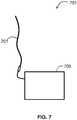
- FIG. 7illustrates a system 701 of the invention.
- System 701includes an instrumented guidewire 201 operably coupled to a computer device 705.
- Guidewire 201includes at least one sensor such as a pressure sensor or flow sensor as discussed above.
- Guidewire 201may include a plurality of sensor such as a pressure sensor and a flow sensor as discussed above.
- Computer 705can be a dedicated medical imaging instrument, a standard desktop, laptop, or tablet computer, or a combination thereof (e.g., a medical imaging instrument with a base station and a laptop or desktop computer attached to provide a workstation and interface for a physician.
- Computer 705can receive a measurement from the sensor on guidewire 201 and use the measurement to determine an observed rate of blood flow through a fistula.
- computer 705compares the observed rate of a blood flow to a standard or an expected rate of blood flow to provide an aid in assessing fistula maturation.
- computer 705may have a software program in memory that stores a standard (e.g., 600 mL/min) flow rate. By making a comparison, if a flow rate is sub-standard, the fistula can be deemed to be not mature. If the flow rate meets the standard, the fistula may be deemed mature.
- the instrumentcan further calculate Coronary Flow Reserve (CFR) - or similar - and Fractional Flow Reserve (FFR) and provide the readings and calculations to a user via a user interface.
- CFRCoronary Flow Reserve
- FFRFractional Flow Reserve
- a userinteracts with a visual interface to view images from the imaging system.
- Input from a usere.g., parameters or a selection
- a computer device or processing instrumentreceives input from a user (e.g., parameters or a selection) from a computer device or processing instrument.
- Electrical signalsare relayed from the conductors via a mating connector (or contact housing as described herein with respect to a connector of the present invention) to an instrument, such as, e.g., a physiology monitor, that converts the signals into pressure and velocity readings that are displayed to the user.
- an instrumentsuch as, e.g., a physiology monitor, that converts the signals into pressure and velocity readings that are displayed to the user.
- algorithmssuch as Coronary Flow Reserve (CFR) - or similar - and Fractional Flow Reserve (FFR) are calculated.
- CFRCoronary Flow Reserve
- FFRFractional Flow Reserve
- System 701may include one or a plurality of computer.
- system 701may include computer 705 as a bed-side workstation or in a control room and system 701 may additionally include a server computer for processing measurements or for receiving measurements from a plurality of cath labs.
- a computer in system 701such as computer 705 generally includes a processor coupled to memory and one or more input/output devices.
- Computer 705may be provided by a desktop computer, laptop, tablet, mobile device, or purpose-built machine (such as a bed-side control station for a medical imaging system).
- a processorgenerally refers to a computer microchip such as the processor sold under the trademark CORE I7 by Intel (Santa Clara, CA).
- Memorygenerally includes one or more devices for random access, storage, or both.
- memoryincludes a tangible, non-transitory computer readable medium, and may be provided by one or more of a solid state drive (SSD), a magnetic disc drive (aka, "a hard drive”), flash memory, an optical drive, others, or a combination thereof.
- SSDsolid state drive
- magnetic disc driveaka, "a hard drive”
- flash memoryan optical drive, others, or a combination thereof.
- An I/O devicemay include one or more of a monitor, keyboard, mouse, touchscreen, Wi-Fi card, cell antenna, Ethernet port, USB port, light, accelerometer, speaker, microphone, drive for removable disc, others, or a combination thereof.
- any combination of computer in system 701may communicate through the use of a network, which may include communication devices for internet communication, telephonic communication, others, or a combination thereof.
- the inventionprovides systems for evaluating the maturation of arteriovenous (AV) fistula using an instrumented guidewire that measures intravascular flow and/or pressure (an FM wire).
- an instrumented guidewirethat measures intravascular flow and/or pressure
- an FM wiremeasures intravascular flow and/or pressure
- an accurate measurementcan be made that is useful for identifying when a fistula is mature and therefore ready to be used for hemodialysis.
- the flow of blood through the fistulais measured using the guidewire and the measured flow of blood is used to determine if the fistula is mature.
- the guidewirehas a flexural modulus of at least 15 GPa and preferably at least 50 GPa.
- the guidewiremay be made with the stiffness of an Amplatz type super-stiff or ultra-stiff guidewire.
- the guidewirecan have a diameter of about 0.014" (0.35 mm) to 0.035" (0.89 mm).
- the guidewiremay have length of less than 120 cm (e.g., about 80 cm).
- the guidewiresmay be provided in a system that includes a computer (that includes a processor coupled to a tangible, non-transitory memory) that analyzes flow measurements to evaluate fistula maturation (e.g., comparing the measured flow to a standard).
- the standardmay be 600 mL/min and the computer can aid the determination that flow that meets or exceeds the standard indicates fistula maturation.
Landscapes
- Health & Medical Sciences (AREA)
- Life Sciences & Earth Sciences (AREA)
- Heart & Thoracic Surgery (AREA)
- Veterinary Medicine (AREA)
- General Health & Medical Sciences (AREA)
- Engineering & Computer Science (AREA)
- Biomedical Technology (AREA)
- Public Health (AREA)
- Animal Behavior & Ethology (AREA)
- Biophysics (AREA)
- Physics & Mathematics (AREA)
- Pathology (AREA)
- Surgery (AREA)
- Molecular Biology (AREA)
- Medical Informatics (AREA)
- Cardiology (AREA)
- Nuclear Medicine, Radiotherapy & Molecular Imaging (AREA)
- Radiology & Medical Imaging (AREA)
- Hematology (AREA)
- Vascular Medicine (AREA)
- Physiology (AREA)
- Anesthesiology (AREA)
- Pulmonology (AREA)
- Electromagnetism (AREA)
- Measuring Pulse, Heart Rate, Blood Pressure Or Blood Flow (AREA)
- Ultra Sonic Daignosis Equipment (AREA)
- External Artificial Organs (AREA)
Description
- The present application claims the benefit of and priority to
U.S. provisional application serial number 61/927,016, filed January 14, 2014 - The invention relates to evaluation of maturity of arteriovenous (AV) fistula using guidewires that measure intravascular blood flow and/or pressure.
- Healthy kidneys remove waste and minerals from the blood. When kidneys fail, harmful waste builds up in the body, blood pressure may rise, and the body may retain excess fluid and not make enough red blood cells due to insufficient erythropoietin production. Hemodialysis is a common method for treating kidney failures and involves flowing blood through a filter to remove wastes. For hemodialysis, a fistula is created that connects an artery to a vein, or optionally an AV graft is created by using a tube to connect the artery to the vein. The National Kidney Foundation (NKF), Centers for Medicare and Medicaid Services (CMS), DaVita Patient Citizens (DPC) and other organizations and experts generally agree that fistulas are the best type of vascular access. After creation, a fistula can take several weeks to develop enough to be used, i.e., to reach fistula maturation. Hemodialysis can be unsuccessful or lead to complications if performed before, or too long after, fistula maturation. The evaluation of maturation by color-flow Doppler ultrasound has been proposed. See, e.g., Toregeani, et al., 2008, Evaluation of hemodialysis arteriovenous fistula maturation by color-flow Doppler ultrasound, J Vasc Bras 7(3):203-213 orFerring, et al., 2008, Vascular ultrasound for the pre-operative evaluation prior to arteriovenous fistula formation for haemodialysis: review of the evidence, Nephrol. Dial. Transplant. 23(6):1809-1815.
- Unfortunately, there are drawbacks associated with those procedures. For example, where the ultrasound catheter reveals that intravascular intervention is called for, the catheter must be swapped for a catheter that can perform the intervention (e.g., thrombectomy). Every removal and insertion of a new catheter raises risk of complications. Additionally, even though the ultrasound catheter itself provides some guidance to a treatment location, it does not provide direct navigational guidance for treatment after having been removed from the body. Further, even though medical organizations recommend fistula access, evaluating maturation is imperfect due to the fact that the ultrasound catheter being used to measure flow also partially impedes that flow. That is, the catheter itself partially occludes flow and interferes with obtaining an actual measurement of flow through an AV fistula.
US 2010/0130864 A1 discloses methods and systems for detecting a maturing arteriovenous fistula. A circumferential vessel wall stress is determined from the measured blood pressure, the wall thickness of the fistula and a determined radius of the measured diameter of the fistula. The determined circumferential vessel stress is compared to a predetermined threshold stress to determine if the fistula is mature.US 2011/0060229 A1 discloses methods and structures for detecting a physiologic parameter of a target anatomical sites for stenotic lesions in grafts and fistulas created for dialysis. A detection device can be used to invasively measure the pressure in these grafts of fistulas (in order to assess their patency and determine whether more expensive tests (e.g. angiography) or procedures (e.g. angioplasty) are warranted.- The invention provides systems for evaluating AV fistula maturation using an instrumented guidewire to measure intravascular blood flow and/or pressure. By using a small diameter guidewire that does not interfere substantially with the flow, an accurate measurement can be made that is useful for identifying when a fistula is mature and therefore ready to be used for hemodialysis. The guidewire can be instrumented to measure flow velocity, pressure, other properties, or a combination thereof. The guidewire can be operated with a system computer that uses the measurement to provide information that aids in evaluating maturity. Fistula maturation is correctly identified, allowing hemodialysis to be initiated at a suitable time, avoiding complications. This lowers cost of hemodialysis while improving results, leading to greater patient health. Additionally, since the quality of the fistula is evaluated by a guidewire, the same guidewire can be used to guide a catheter to a location proximal to where the measurement is made. Thus, where the guidewire detects or reveals a need for therapy, the guidewire can be used to guide delivery of the therapy via a catheter, without the need for a catheter exchange, thus decreasing complications associated with catheter exchanges.
- Assessing maturation of a fistula includes inserting an instrumented guidewire into a vessel of a patent, according to the disclosure. The vessel is in communication with a fistula, which provides fluid communication between the vessel and an adjacent vessel. For example, an arteriovenous fistula for hemodialysis may be assessed. The flow of blood through the fistula is measured using the guidewire and the measured flow of blood is used to determine if the fistula is mature. Measuring the flow of blood may include collecting data with a sensing device on the guidewire while the guidewire is within the vessel and relaying the data to a computer. The computer determines an observed rate of the flow of blood. Preferably a computer program is used to provide information about the maturity of the fistula based on the observed rate of blood flow. Determining maturation may be done by comparing the observed rate to a standard. For example, an observed rate of 600 mL/ min or greater may indicate that the fistula is mature. The instrumented guidewire may include an ultrasonic transducer (e.g., for Doppler velocity), a pressure sensor, other sensors, or a combination thereof.
- The guidewire may be specially designed for arteriovenous hemodialysis fistula. For example, the guidewire may be shorter than other intravascular guidewires, stiffer, or both. The guidewire may have a diameter of about 0.035 inches or less. In some embodiments, the guidewire is less than about 110 cm long, and preferably less than about 80 cm long (e.g., about 50 to 60 cm long). The guidewire can include a stiffening material to give it a desires flexural modulus (e.g., at least about 15 GPa, or at least about 50 GPa). In some embodiments, the guidewire will have a stiffness of 100 GPa flexural modulus or greater.
- The method according to the disclosure further includes sliding a catheter over the guidewire and using the catheter over the guidewire to deliver therapy to the fistula.
- Aspects of the invention provide a system for assessing maturation of a fistula. The system includes a sensing guidewire comprising a sensor and configured to be inserted into a vessel of a patient, wherein the vessel comprises a fistula providing fluid communication between the vessel and an adjacent vessel, and a computer communicatively linked with the sensing guidewire. The computer receives a measurement from the sensor, uses the measurement to determine an observed rate of blood flow through a fistula, and uses the determined observed rate of blood flow for determining if the fistula is mature. The system optionally can include a catheter to deliver therapy to the fistula. Preferably, the computer includes a program in memory that causes the computer to provide information about the maturity of the fistula based on the observed rate of blood flow.
FIG. 1 diagrams a method of using a guidewire to assess fistula maturation.FIG. 2 illustrates a guidewire with a pressure sensor.FIG. 3 illustrates a guidewire with a flow sensor.FIG. 4 shows a guidewire tip with a flow sensor and a pressure sensor.FIG. 5 gives a cross-sectional view through a guidewire tip.FIG. 6 shows conductors passing through a guide wire.FIG. 7 illustrates a system of the invention.- Methods according to the disclosure use a guidewire with one or more sensor to obtain intraluminal measurements within a body lumen. The sensors are preferably coupled to signal wires such as electrical conductors, which relay signals between the sensors and a workstation. A guidewire of the invention can include a pressure sensor, a flow sensor, a temperature sensor or combinations thereof. Preferably, the guidewire is a combination guidewire that includes both a pressure sensor and a flow sensor. Pressure sensors can be used to measure pressure within the lumen and flow sensors can be used to measure the velocity of blood flow. Temperature sensors can measure the temperature of a lumen. A guidewire with both a pressure sensor and a flow sensor provides a desirable environment in which to calculate fractional flow reserve (FFR) using pressure readings, and coronary flow reserve (CFR), or non-coronary vessel flow reserve, using flow readings.
FIG. 1 diagrams amethod 101 of using a functional management wire (FM wire) to assess maturation of AV fistulas or grafts. Use of a wire results in less vessel obstruction than a catheter and offers the ability to intervene over the FM wire at the time of the procedure. An FM wire could provide flow measurements, pressure measurements, others, or a combination thereof.- Functional management is a guide wire based technology that analyzes pressure, flow, or both from the inside of a vessel. The wire provides a simple, reproducible measurement, and may be used in conjunction with angiography.
Method 101 starts 105 with a patient with an AV fistula. An instrumented guidewire is inserted 109 into the appropriate vessel to make measurements proximal (e.g., at or near) the AV fistula. In some embodiments, the guidewire is inserted 109 into the vein immediately downstream of the fistula. Preferably, measurements are made where flow is laminar. Measurements may be made following generally procedure described inRobbin, et al., 2002, Hemodialysis arteriovenous fistula maturity: US evaluation, Radiology 225(1):59-64. The flow of blood through the fistula or graft is measured 117.- The observed flow is blood is compared 121 to a standard (e.g., for a binary yes/no call, or to stratify). This can be done using a computer that receives data from the guidewire. The computer can further provide 127 a result supporting a determination of whether the fistula is mature. Any suitable instrumented guidewire can be used to measure 117 the blood flow. For example, a functional management guidewire can be used.
FIG. 2 illustrates aguidewire 201 with apressure sensor 204.Guidewire 201 generally defines an elongated body extending from aproximal end 210 to adistal end 202.Proximal end 210 connects toconnector housing 215, which offers amodular plug 221 for connection to a computing device in systems of the invention.- A pressure sensor allows one to obtain pressure measurements within a body lumen. A particular benefit of pressure sensors is that pressure sensors allow one to measure of fractional flow reserve (FFR) in vessel, which is a comparison of the pressure within a vessel at positions prior to the fistula and after the fistula. The level of FFR determines the patency of the fistula, which allows physicians to more accurately identify fistula maturation. For example, an FFR measurement above 0.80 may indicate maturation. Another benefit is that a physician can measure the pressure before and after an intraluminal intervention procedure to determine the impact of the procedure.
Pressure sensor 204 can be mounted on the distal portion of a flexible elongate member. In certain embodiments, the pressure sensor is positioned distal to the compressible and bendable coil segment of the elongate member. This allows the pressure sensor to move away from the longitudinal axis and coil segment as bended. The pressure sensor can be formed of a crystal semiconductor material having a recess therein and forming a diaphragm bordered by a rim. A reinforcing member is bonded to the crystal and reinforces the rim of the crystal and has a cavity therein underlying the diaphragm and exposed to the diaphragm. A resistor having opposite ends is carried by the crystal and has a portion thereof overlying a portion of the diaphragm. Electrical conductor wires can be connected to opposite ends of the resistor and extend within the flexible elongate member to the proximal portion of the flexible elongate member. Additional details of suitable pressure sensors that may be used with devices of the invention are described inU.S. Pat. No. 6,106,476 .U.S. Pat. No. 6,106,476 also describes suitable methods for mounting thepressure sensor 404 within a sensor housing. As discussed above, additionally or alternatively, a guidewire can include a flow sensor. In some embodiments, a guidewire is used that includes a flow sensor. A suitable product forguidewire 201 is the PrimeWire PRESTIGE from Volcano Corporation.- In general, the guide wire of the present invention is comprised of a flexible elongate element having proximal and distal ends and a diameter of 0.018" and less as disclosed in
U.S. Pat. No. 5,125,137 ,U.S. Pat. No. 5,163,445 ,U.S. Pat. No. 5,174,295 ,U.S. Pat. No. 5,178,159 ,U.S. Pat. No. 5,226,421 ,U.S. Pat. No. 5,240,437 andU.S. Pat. No. 6,106,476 . - A guidewire of the invention may include a flexible elongate element having proximal and distal extremities, and can be formed of a suitable material such as stainless steel, Nitinol, polyimide, PEEK or other metallic or polymeric materials having an outside diameter for example of 0.018" or less and having a suitable wall thickness, such as, e.g., 0.001" to 0.002". This flexible elongate element is conventionally called a hypotube. In one embodiment, the hypotube may have a length of less than 120 cm, preferably about 50, 60, 70, or 80 cm. Typically, such a guide wire may further include a stainless steel core wire extending from the proximal extremity to the distal extremity of the flexible elongate element to provide the desired torsional properties to facilitate steering of the guide wire in the vessel and to provide strength to the guidewire and prevent kinking.
- In a preferred embodiment, methods according to the disclosure employ a guidewire with improved stiffness, relative to prior art guidewires. For example, the guidewire can include a stiffening material such as a stainless steel core or a less pliable plastic (e.g., less pliable than Nitinol, polyimide, or PEEK). Preferably, the guidewire has a flexural modulus of at least 15 GPa. In some embodiments, the guidewire has a flexural modulus of at least 50 GPa (e.g., as measured and described inHarrison et al., 2011, What's in a name?, J Endo Ther 18(6):797-801). For example, the guidewire may be made with the stiffness of an Amplatz type super-stiff or ultra-stiff guidewire. The guidewire can have a diameter of about 0.014" (0.35 mm) and can include the functional instrumentation of the Doppler guide wire sold under the name FLOWIRE by Volcano Corporation, the pressure guidewire sold under the name PRIMEWIRE PRESTIGE by Volcano Corporation, or both.
FIG. 3 illustrates aguidewire 201 with aflow sensor 305. The flow sensor can be used to measure blood flow velocity within the vessel, which can be used to assess coronary flow reserve (CFR), or similar. The flow sensor can be, for example, an ultrasound transducer, a Doppler flow sensor or any other suitable flow sensor, disposed at or in close proximity to the distal tip of the guidewire. The ultrasound transducer may be any suitable transducer, and may be mounted in the distal end using any conventional method, including the manner described inU.S. Pat. No. 5,125,137 ,6,551,250 and5,873,835 . A suitable product forguidewire 201 with aflow sensor 305 is the FLOWIRE from Volcano Corporation.- In a preferred embodiment, methods according to the disclosure employ a guidewire that includes a device for measuring pressure and a device for measuring flow. For example, in use, the guidewire may be advanced to a fistula. The pressure and flow velocity may then be measured.
- The ability to take the pressure and flow measurements at the same location and same time with the combination tip sensor, improves the accuracy of the diagnostic information.
FIG. 4 shows acombination sensor tip 400 of aguidewire 201 according to embodiments of the present invention. Thecombination sensor tip 400 includes apressure sensor 404 withinsensor housing 403, and optionally includes aradiopaque tip coil 405 distal toproximal coil 406.FIG. 5 gives a cross-sectional view throughcombination sensor tip 400, showingultrasound transducer 501 disposed therein. Theultrasound transducer 501 may be any suitable transducer, and may be mounted in the distal end using any conventional method, including the manner described inU.S. Pat. No. 5,125,137 . Conductors (not shown) may be secured to the front and rear sides of theultrasound transducer 501, and the conductors may extend interiorly to the proximal extremity of a guide wire.- The
combination sensor tip 400 also includes apressure sensor 404 also disposed at or in close proximity to thedistal end 202 of thecombination sensor tip 400. Thepressure sensor 404 may be of the type described inU.S. Pat. No. 6,106,476 . For example, thepressure sensor 404 may be comprised of a crystal semiconductor material having a recess therein and forming a diaphragm bordered by a rim. A reinforcing member may be bonded to the crystal to reinforce the rim of the crystal, and may have a cavity therein underlying the diaphragm and exposed to the diaphragm. A resistor having opposite ends may be carried by the crystal and may have a portion thereof overlying a portion of the diaphragm. Leads may be connected to opposite ends of the resistor and extend proximally within the guide wire. Additional details of suitable pressure sensors that may be used as thepressure sensor 404 are described inU.S. Pat. No. 6,106,476 .U.S. Pat. No. 6,106,476 also describes suitable methods for mounting thepressure sensor 404 within thecombination sensor tip 400. In one embodiment, thepressure sensor 404 is oriented in a cantilevered position within asensor housing 403. For example, thesensor housing 403 preferably includes a lumen surrounded by housing walls. When in a cantilevered position, thepressure sensor 404 projects into the lumen of thesensor housing 403 without contacting the walls of thesensor housing 403. - In
FIG. 5 ,ultrasound transducer 501 is illustrated as disposed neardistal end 202. One advantage of thesensor housing 403 is that because thesensor housing 403 encloses both theultrasound transducer 501 and thepressure sensor 404, the need for two separate housings, i.e., one for an ultrasound transducer and one for a pressure sensor, is eliminated. Accordingly, the use of acommon sensor housing 403 for theultrasound transducer 501 and thepressure sensor 404 makes thecombination sensor tip 400 easier to manufacture than current designs. - Additionally, the
combination sensor tip 400 of the present invention provides for both theultrasound transducer 501 and thepressure sensor 404 to be disposed near the distal end of thecombination sensor tip 400. Thecombination sensor tip 400 of the present invention is advantageous because by having both theultrasound transducer 501 and thepressure sensor 404 near its distal end, thecombination sensor tip 400 is capable of being positioned distally beyond the fistula. Additionally, thecombination sensor tip 400 of the present invention, unlike the prior art, is also able to take measurements from theultrasound transducer 501 and the pressure 104 at approximately the same location and approximately the same time, thereby resulting in greater consistency of measurements, greater accuracy of measurements, and greater accuracy of placement within the body. Furthermore, placement of both theultrasound transducer 501 and thepressure sensor 404 near the distal end of thecombination sensor tip 400 increases overall flexibility in a guide wire that incorporates thecombination sensor tip 400. For example, a prior art guide wire that includes separate sensors, with the pressure sensor being located substantially proximal from the ultrasound transducer, has a longer relatively rigid area that must be devoted to the pressure and flow sensors, i.e., the distance from the ultrasound transducer to the pressure sensor. The present invention, in contrast, substantially reduces or entirely eliminates the distance between the ultrasound transducer and the pressure sensor, thereby allowing for increased flexibility across this length. - It should be noted that in an alternative embodiment of the combination sensor tip 400 (not shown) both the
ultrasound transducer 501 and thepressure sensor 404 may be offset from the distal end of thecombination sensor tip 400, such as, e.g., 1.5 cm to 3.0 cm from the distal end, but still located in close proximity to each other relative to prior art designs. Thus, the aforementioned advantages over the prior art design are still achieved. - In an alternative embodiment, the pressure sensor housing includes a tubular member having an opening on the outer wall in communication with the lumen and a tip. The tip is constructed of a solder ball. Alternatively a weld, braze, epoxy or adhesive can be used. The lumen of the housing is counter-bored so that the lumen has a smaller inner diameter at the proximal end of the tubular member. For example, the housing may be constructed in the counter-bore fashion with a 0.010" inner diameter at the proximal end and a 0.012" inner diameter at the distal end, with the pressure transducer coaxially housed in the lumen. In addition, a flow sensor may be placed in the sensor tip instead of the weld, braze, epoxy or adhesive to provide a combo sensor tip. The advantage of the counter bore is that the housing is easier to make. The transducer is simply slid into place in the lumen and bonded (adhesive or epoxy) where the sides meet the proximal 0.010" inner diameter 314. The distal 0.012" inner diameter allows enough room for the pressure sensitive section of the transducer to be free from any contact with the housing. Because of the counter-bored lumen, there is no ledge that has to be made on the outer wall of the lumen, rather the pressure transducer communicates with the outside via an opening in the outer wall of lumen. Constructions suitable for use with a guidewire of the invention are discussed in
U.S. Pub. 2013/0030303 A1 . - A
radiopaque tip coil 405 may be provided at the proximal end of thecombination sensor tip 400. Theradiopaque tip coil 405 is coupled to a proximal coil 106, and the proximal coil 106 may be coupled to the elongate tubular member. Another improvement of the present invention over current designs that use separate pressure sensor and ultrasound transducer housings is that the present invention provides a smoother transition from the elongate tubular member to thecombination sensor tip 400, i.e., the connection between theradiopaque tip coil 405, the proximal coil 106, and the rest of the guide wire is optimized relative to current designs. Specifically, the transition is smoother and more flexible because of the absence of the housing between theradiopaque tip coil 405 and the proximal coil 106. Current designs generally have a tip coil 5 attached to a pressure sensor housing 3, which in turn is connected to a proximal coil 6. The present invention eliminates or greatly reduces the separation between the tip coil and the proximal coil that is required in current devices. Suitable coils for use with the present invention are described inU.S. Pat. No. 6,106,476 . FIG. 6 showsfine wire conductors 607 passing through the guide wire toconductive bands 608 near theproximal end 210 of the guide wire. Signals from theultrasound transducer 501 and thepressure sensor 404 may be carried byconductors 607. Usually three electrical connectors are necessary for a stand-alone pressure measurement guidewire and two electrical connectors are necessary for a stand-alone flow measurement guidewire. Thus, a guide wire incorporating thecombination sensor tip 400 of the present invention includes fiveelectrical conductors 607 extending through the lumen of the guidewire and fiveconductive bands 608 on the proximal end 610 of the guidewire. Theconductive bands 608 may be electrically isolated from each other by means ofepoxy 609. Alternatively, polyimide tubes may be used to isolate conductors from the conductive bands.- The electrical connection wires can include a conductive core made from a conductive material, such as copper, and an insulating coating, such as a polyimide, Fluoro-polymer, or other insulating material. The electrical connection wires extend from one or more sensors located on the distal end of the guidewire, run down the length of the guidewire, and connect to a connector housing at a proximal end.
- Any suitable arrangement of the electrical connection wires through the length of the elongate member can be used. The arrangement of electrical connection wires must provide for a stable connection from the proximal end of the guidewire to the distal end of the guidewires. In addition, the electrical connection wires must be flexible and/or have enough slack to bend and/or move with the adjustable distal portion without disrupting the sensor connection. In one embodiment, the electrical connections run next the core member within the lumen of the elongate member.
- In yet another embodiment, the electrical connector wires 707 are wrapped around a core member of the guidewire and then covered with a polyimide layer. At a distal end of the core member near the sensors, the polyimide layer can be dissected away, which frees the wires to extend and connect to their respective sensors. The length of the electrical connector wire running free from the core member and connected to the sensor should have enough slack/flexibility to remain connected to the sensor during bending of the guidewire.
- Preferably, proximal end 610 connects to
connector housing 215 as shown inFIG. 2 . In certain embodiments, the electrical connector wires are joined together to form a male connector at a proximal end. The male connector mates with a female connector of the connector housing. The termination of the male connector can be performed by a metal deposition process as described inU.S. Pat. No. 6,210,339 . The deposited metal (or any conductive material) permanently adheres or couples to the exposed conductive wires at points where the polyimide layers were removed. After the masking material is removed, there are independent conductive stripes, each connected to a different respective electric wire. Because of the precision nature of the winding process as well as the masking and metal deposition processes, a male connector is made that is short in length, yet very reliable, in mating with a female connector and cable. Alternatively, conductive bands may be coupled to the exposed ends of the electric wires instead of the metallizing process. - The connector housing can be connected to an instrument, such as a computing device (e.g. a laptop, desktop, or tablet computer) or a physiology monitor that converts the signals received by the sensors into pressure and velocity readings in systems of the invention.
- In advanced embodiments, the systems of the invention incorporate focused acoustic computed tomography (FACT), which is described in
WO2014/109879 .FIG. 7 illustrates asystem 701 of the invention.System 701 includes an instrumentedguidewire 201 operably coupled to acomputer device 705.Guidewire 201 includes at least one sensor such as a pressure sensor or flow sensor as discussed above.Guidewire 201 may include a plurality of sensor such as a pressure sensor and a flow sensor as discussed above.Computer 705 can be a dedicated medical imaging instrument, a standard desktop, laptop, or tablet computer, or a combination thereof (e.g., a medical imaging instrument with a base station and a laptop or desktop computer attached to provide a workstation and interface for a physician.Computer 705 can receive a measurement from the sensor onguidewire 201 and use the measurement to determine an observed rate of blood flow through a fistula. In some embodiments,computer 705 compares the observed rate of a blood flow to a standard or an expected rate of blood flow to provide an aid in assessing fistula maturation. For example,computer 705 may have a software program in memory that stores a standard (e.g., 600 mL/min) flow rate. By making a comparison, if a flow rate is sub-standard, the fistula can be deemed to be not mature. If the flow rate meets the standard, the fistula may be deemed mature. The instrument can further calculate Coronary Flow Reserve (CFR) - or similar - and Fractional Flow Reserve (FFR) and provide the readings and calculations to a user via a user interface. - In some embodiments, a user interacts with a visual interface to view images from the imaging system. Input from a user (e.g., parameters or a selection) are received by a computer device or processing instrument. Electrical signals are relayed from the conductors via a mating connector (or contact housing as described herein with respect to a connector of the present invention) to an instrument, such as, e.g., a physiology monitor, that converts the signals into pressure and velocity readings that are displayed to the user. In addition algorithms such as Coronary Flow Reserve (CFR) - or similar - and Fractional Flow Reserve (FFR) are calculated.
System 701 may include one or a plurality of computer. For example,system 701 may includecomputer 705 as a bed-side workstation or in a control room andsystem 701 may additionally include a server computer for processing measurements or for receiving measurements from a plurality of cath labs. A computer insystem 701 such ascomputer 705 generally includes a processor coupled to memory and one or more input/output devices.Computer 705 may be provided by a desktop computer, laptop, tablet, mobile device, or purpose-built machine (such as a bed-side control station for a medical imaging system).- A processor generally refers to a computer microchip such as the processor sold under the trademark CORE I7 by Intel (Santa Clara, CA).
- Memory generally includes one or more devices for random access, storage, or both. Preferably, memory includes a tangible, non-transitory computer readable medium, and may be provided by one or more of a solid state drive (SSD), a magnetic disc drive (aka, "a hard drive"), flash memory, an optical drive, others, or a combination thereof.
- An I/O device may include one or more of a monitor, keyboard, mouse, touchscreen, Wi-Fi card, cell antenna, Ethernet port, USB port, light, accelerometer, speaker, microphone, drive for removable disc, others, or a combination thereof. Preferably, any combination of computer in
system 701 may communicate through the use of a network, which may include communication devices for internet communication, telephonic communication, others, or a combination thereof. - As will be appreciated from the above, the invention provides systems for evaluating the maturation of arteriovenous (AV) fistula using an instrumented guidewire that measures intravascular flow and/or pressure (an FM wire). By using a small diameter guidewire that does not interfere substantially with the flow, an accurate measurement can be made that is useful for identifying when a fistula is mature and therefore ready to be used for hemodialysis. The flow of blood through the fistula is measured using the guidewire and the measured flow of blood is used to determine if the fistula is mature. Preferably, the guidewire has a flexural modulus of at least 15 GPa and preferably at least 50 GPa. The guidewire may be made with the stiffness of an Amplatz type super-stiff or ultra-stiff guidewire. The guidewire can have a diameter of about 0.014" (0.35 mm) to 0.035" (0.89 mm). The guidewire may have length of less than 120 cm (e.g., about 80 cm). The guidewires may be provided in a system that includes a computer (that includes a processor coupled to a tangible, non-transitory memory) that analyzes flow measurements to evaluate fistula maturation (e.g., comparing the measured flow to a standard). The standard may be 600 mL/min and the computer can aid the determination that flow that meets or exceeds the standard indicates fistula maturation.
- Various modifications of the invention and many further embodiments thereof, in addition to those shown and described herein, will become apparent to those skilled in the art from the full contents of this document, including references to the scientific and patent literature cited herein. The subject matter herein contains important information, exemplification and guidance that can be adapted to the practice of this invention in its various embodiments and equivalents thereof.
Claims (11)
- A system for assessing maturation of a fistula, the system comprising:a sensing guidewire comprising a sensor and configured to be inserted into a vessel of a patient, the vessel comprising a fistula providing fluid communication between the vessel and an adjacent vessel; anda computer communicatively linked with the sensing guidewire, the computer operable to receive a measurement from the sensor, use the measurement to determine an observed rate of blood flow through the fistula and use the determined observed rate of blood flow for determining if the fistula is mature.
- The system of claim 1, further comprising a catheter slidably disposed over the guidewire configured to deliver therapy to the fistula.
- The system of claim 1, wherein the sensing guidewire comprises an ultrasonic transducer and a modular connection plug.
- The system of claim 1, wherein the guidewire has a diameter of 0.035 inches or less.
- The system of claim 1, wherein determining if the fistula is mature comprises comparing the observed rate to a standard.
- The system of claim 1, wherein an observed rate of 600 mL/ min or greater indicates that the fistula is mature.
- The system of claim 1, wherein the sensor comprises a pressure sensor.
- The system of claim 1, wherein the computer comprises a program in memory, the program comprising instructions executable to cause the computer to provide information about the maturity of the fistula based on the observed rate of blood flow.
- The system of claim 1, wherein the guidewire is less than 110 cm long and comprises a stiffening material.
- The system of claim 9, wherein the guidewire has a flexural modulus of at least 15 GPa.
- The system of claim 9, wherein the guidewire has a flexural modulus of at least 50 GPa.
Applications Claiming Priority (2)
| Application Number | Priority Date | Filing Date | Title |
|---|---|---|---|
| US201461927016P | 2014-01-14 | 2014-01-14 | |
| PCT/US2015/011337WO2015108928A1 (en) | 2014-01-14 | 2015-01-14 | Systems and methods for evaluating hemodialysis arteriovenous fistula maturation |
Publications (2)
| Publication Number | Publication Date |
|---|---|
| EP3094241A1 EP3094241A1 (en) | 2016-11-23 |
| EP3094241B1true EP3094241B1 (en) | 2018-07-04 |
Family
ID=52474066
Family Applications (1)
| Application Number | Title | Priority Date | Filing Date |
|---|---|---|---|
| EP15704866.1AActiveEP3094241B1 (en) | 2014-01-14 | 2015-01-14 | Systems and methods for evaluating hemodialysis arteriovenous fistula maturation |
Country Status (5)
| Country | Link |
|---|---|
| US (2) | US10251606B2 (en) |
| EP (1) | EP3094241B1 (en) |
| JP (1) | JP6389526B2 (en) |
| CN (1) | CN106163386B (en) |
| WO (1) | WO2015108928A1 (en) |
Families Citing this family (20)
| Publication number | Priority date | Publication date | Assignee | Title |
|---|---|---|---|---|
| US10780298B2 (en) | 2013-08-22 | 2020-09-22 | The Regents Of The University Of Michigan | Histotripsy using very short monopolar ultrasound pulses |
| EP3094241B1 (en)* | 2014-01-14 | 2018-07-04 | Volcano Corporation | Systems and methods for evaluating hemodialysis arteriovenous fistula maturation |
| JP6979882B2 (en) | 2015-06-24 | 2021-12-15 | ザ リージェンツ オブ ザ ユニヴァシティ オブ ミシガン | Tissue disruption therapy systems and methods for the treatment of brain tissue |
| US11786140B2 (en) | 2019-08-21 | 2023-10-17 | Corflow Therapeutics Ag | Controlled-flow infusion catheter and method |
| US11607174B2 (en) | 2016-11-28 | 2023-03-21 | Sensome SAS | Insertable device for in vivo sensing |
| CN106669109B (en)* | 2017-01-25 | 2022-03-22 | 湖州市中心医院 | An arteriovenous fistula promoting maturation exerciser |
| WO2018175485A1 (en)* | 2017-03-20 | 2018-09-27 | Corflow Therapeutics Ag | Combined stent reperfusion system |
| CN111655121B (en) | 2017-09-19 | 2024-05-24 | 康福乐医疗公司 | Intracoronary characterization of microvascular occlusion (MVO) and myocardial infarction |
| WO2019232452A1 (en) | 2018-05-31 | 2019-12-05 | Bernard Andre | Microfluidic coronary circulatory model |
| AU2019343998B2 (en) | 2018-09-21 | 2025-05-01 | Corflow Therapeutics Ag | Apparatus for assessment of microvascular dysfunction |
| AU2019389001B2 (en) | 2018-11-28 | 2025-08-14 | Histosonics, Inc. | Histotripsy systems and methods |
| US11426503B2 (en)* | 2019-01-16 | 2022-08-30 | Fresenius Medical Care Holdings, Inc. | Arteriovenus fistula maturation monitoring systems and methods |
| US11813485B2 (en) | 2020-01-28 | 2023-11-14 | The Regents Of The University Of Michigan | Systems and methods for histotripsy immunosensitization |
| CN114052673B (en)* | 2020-07-30 | 2024-07-12 | 深圳市理邦精密仪器股份有限公司 | Fistula maturity assessment method, fistula maturity assessment device and fistula maturity assessment storage medium |
| JP2023540482A (en) | 2020-08-27 | 2023-09-25 | ザ リージェンツ オブ ザ ユニバーシティー オブ ミシガン | Ultrasonic transducer with transmitting and receiving functions for histotripsy |
| CN118871039A (en) | 2022-01-12 | 2024-10-29 | 皇家飞利浦有限公司 | Intravascular Doppler blood flow measurement from an intravascular guidewire for vascular assessment |
| CN114515144A (en)* | 2022-02-21 | 2022-05-20 | 复旦大学附属中山医院 | System for detecting flow rate and pressure of thoracic aortic dissection false cavity and in-vivo measurement method |
| EP4472718A2 (en)* | 2022-03-21 | 2024-12-11 | Becton, Dickinson and Company | Closed system flexible vascular access device sensor deployment system |
| CN115282465B (en)* | 2022-08-16 | 2023-10-10 | 心擎医疗(苏州)股份有限公司 | In-vitro blood pump system based on-line instant feedback control of blood pressure |
| EP4608504A1 (en) | 2022-10-28 | 2025-09-03 | Histosonics, Inc. | Histotripsy systems and methods |
Family Cites Families (103)
| Publication number | Priority date | Publication date | Assignee | Title |
|---|---|---|---|---|
| US4794931A (en) | 1986-02-28 | 1989-01-03 | Cardiovascular Imaging Systems, Inc. | Catheter apparatus, system and method for intravascular two-dimensional ultrasonography |
| US5000185A (en) | 1986-02-28 | 1991-03-19 | Cardiovascular Imaging Systems, Inc. | Method for intravascular two-dimensional ultrasonography and recanalization |
| US5163445A (en) | 1987-04-10 | 1992-11-17 | Cardiometrics, Inc. | Apparatus, system and method for measuring spatial average velocity and/or volumetric flow of blood in a vessel and screw joint for use therewith |
| US5174295A (en) | 1987-04-10 | 1992-12-29 | Cardiometrics, Inc. | Apparatus, system and method for measuring spatial average velocity and/or volumetric flow of blood in a vessel and screw joint for use therewith |
| US4841977A (en) | 1987-05-26 | 1989-06-27 | Inter Therapy, Inc. | Ultra-thin acoustic transducer and balloon catheter using same in imaging array subassembly |
| US4917097A (en) | 1987-10-27 | 1990-04-17 | Endosonics Corporation | Apparatus and method for imaging small cavities |
| US4951677A (en) | 1988-03-21 | 1990-08-28 | Prutech Research And Development Partnership Ii | Acoustic imaging catheter and the like |
| US5372138A (en) | 1988-03-21 | 1994-12-13 | Boston Scientific Corporation | Acousting imaging catheters and the like |
| US5240437A (en) | 1988-11-02 | 1993-08-31 | Cardiometrics, Inc. | Torqueable guide wire assembly with electrical functions, male and female connectors for use therewith and system and apparatus for utilizing the same |
| US5178159A (en) | 1988-11-02 | 1993-01-12 | Cardiometrics, Inc. | Torqueable guide wire assembly with electrical functions, male and female connectors rotatable with respect to one another |
| US5240003A (en) | 1989-10-16 | 1993-08-31 | Du-Med B.V. | Ultrasonic instrument with a micro motor having stator coils on a flexible circuit board |
| NL8902559A (en) | 1989-10-16 | 1991-05-16 | Du Med Bv | INTRA-LUMINAL DEVICE. |
| US5095911A (en) | 1990-05-18 | 1992-03-17 | Cardiovascular Imaging Systems, Inc. | Guidewire with imaging capability |
| US5135486A (en) | 1990-08-31 | 1992-08-04 | Endosonics Corporation | Self-venting balloon dilitation catheter |
| US5125137A (en) | 1990-09-06 | 1992-06-30 | Cardiometrics, Inc. | Method for providing a miniature ultrasound high efficiency transducer assembly |
| US5167233A (en) | 1991-01-07 | 1992-12-01 | Endosonics Corporation | Dilating and imaging apparatus |
| US5304115A (en) | 1991-01-11 | 1994-04-19 | Baxter International Inc. | Ultrasonic angioplasty device incorporating improved transmission member and ablation probe |
| US5243988A (en) | 1991-03-13 | 1993-09-14 | Scimed Life Systems, Inc. | Intravascular imaging apparatus and methods for use and manufacture |
| US5353798A (en) | 1991-03-13 | 1994-10-11 | Scimed Life Systems, Incorporated | Intravascular imaging apparatus and methods for use and manufacture |
| US6111645A (en) | 1991-04-29 | 2000-08-29 | Massachusetts Institute Of Technology | Grating based phase control optical delay line |
| JP3479069B2 (en) | 1991-04-29 | 2003-12-15 | マサチューセッツ・インステチュート・オブ・テクノロジー | Method and apparatus for optical imaging and measurement |
| US6134003A (en) | 1991-04-29 | 2000-10-17 | Massachusetts Institute Of Technology | Method and apparatus for performing optical measurements using a fiber optic imaging guidewire, catheter or endoscope |
| US5183048A (en) | 1991-06-24 | 1993-02-02 | Endosonics Corporation | Method and apparatus for removing artifacts from an ultrasonically generated image of a small cavity |
| JP2894390B2 (en) | 1992-01-10 | 1999-05-24 | 三菱電機株式会社 | Scroll compressor |
| US5226421A (en) | 1992-03-06 | 1993-07-13 | Cardiometrics, Inc. | Doppler elongate flexible member having an inflatable balloon mounted thereon |
| US5373845A (en) | 1992-05-22 | 1994-12-20 | Echo Cath, Ltd. | Apparatus and method for forward looking volume imaging |
| US5348017A (en) | 1993-01-19 | 1994-09-20 | Cardiovascular Imaging Systems, Inc. | Drive shaft for an intravascular catheter system |
| US5373849A (en) | 1993-01-19 | 1994-12-20 | Cardiovascular Imaging Systems, Inc. | Forward viewing imaging catheter |
| US5453575A (en) | 1993-02-01 | 1995-09-26 | Endosonics Corporation | Apparatus and method for detecting blood flow in intravascular ultrasonic imaging |
| US5368037A (en) | 1993-02-01 | 1994-11-29 | Endosonics Corporation | Ultrasound catheter |
| US5873835A (en) | 1993-04-29 | 1999-02-23 | Scimed Life Systems, Inc. | Intravascular pressure and flow sensor |
| DE69534748T2 (en) | 1994-09-02 | 2006-11-02 | Volcano Corp. (n.d, Ges.d.Staates Delaware), Rancho Cordova | ULTRAMINIATUR PRESSURE SENSOR AND GUIDE WIRE THEREFORE |
| US6283951B1 (en) | 1996-10-11 | 2001-09-04 | Transvascular, Inc. | Systems and methods for delivering drugs to selected locations within the body |
| US6302875B1 (en) | 1996-10-11 | 2001-10-16 | Transvascular, Inc. | Catheters and related devices for forming passageways between blood vessels or other anatomical structures |
| ATE440559T1 (en) | 1995-10-13 | 2009-09-15 | Medtronic Vascular Inc | DEVICE FOR INTERSTITIAL TRANSVASCULAR PROCEDURES |
| US6375615B1 (en) | 1995-10-13 | 2002-04-23 | Transvascular, Inc. | Tissue penetrating catheters having integral imaging transducers and their methods of use |
| US6726677B1 (en) | 1995-10-13 | 2004-04-27 | Transvascular, Inc. | Stabilized tissue penetrating catheters |
| DE69633411T2 (en) | 1995-10-13 | 2005-10-20 | Transvascular, Inc., Menlo Park | METHOD AND DEVICE FOR PREVENTING ARTERIAL ATTRACTIONS AND / OR FOR CARRYING OUT OTHER TRANSVASCULAR INTERVENTIONS |
| AU733341B2 (en) | 1996-02-02 | 2001-05-10 | Transvascular, Inc. | A device, system and method for interstitial transvascular intervention |
| US6709444B1 (en) | 1996-02-02 | 2004-03-23 | Transvascular, Inc. | Methods for bypassing total or near-total obstructions in arteries or other anatomical conduits |
| US5771895A (en) | 1996-02-12 | 1998-06-30 | Slager; Cornelis J. | Catheter for obtaining three-dimensional reconstruction of a vascular lumen and wall |
| US5830224A (en) | 1996-03-15 | 1998-11-03 | Beth Israel Deaconess Medical Center | Catheter apparatus and methodology for generating a fistula on-demand between closely associated blood vessels at a pre-chosen anatomic site in-vivo |
| WO1999058059A1 (en) | 1998-03-05 | 1999-11-18 | Vardi Gil M | Optical-acoustic imaging device |
| AU762604B2 (en) | 1998-03-31 | 2003-06-26 | Transvascular, Inc. | Catheters, systems and methods for percutaneous in situ arterio-venous bypass |
| US6210339B1 (en) | 1999-03-03 | 2001-04-03 | Endosonics Corporation | Flexible elongate member having one or more electrical contacts |
| US6381350B1 (en) | 1999-07-02 | 2002-04-30 | The Cleveland Clinic Foundation | Intravascular ultrasonic analysis using active contour method and system |
| US6200268B1 (en) | 1999-09-10 | 2001-03-13 | The Cleveland Clinic Foundation | Vascular plaque characterization |
| US6457365B1 (en) | 2000-02-09 | 2002-10-01 | Endosonics Corporation | Method and apparatus for ultrasonic imaging |
| US6508824B1 (en) | 2000-02-18 | 2003-01-21 | Transvascular, Inc. | Catheter-based methods for enlarging blood vessels to facilitate the formation of penetration tracts, fistulas and/or blood flow channels |
| US20010031981A1 (en) | 2000-03-31 | 2001-10-18 | Evans Michael A. | Method and device for locating guidewire and treating chronic total occlusions |
| US6602241B2 (en) | 2001-01-17 | 2003-08-05 | Transvascular, Inc. | Methods and apparatus for acute or chronic delivery of substances or apparatus to extravascular treatment sites |
| US6551250B2 (en) | 2001-03-29 | 2003-04-22 | Hassan Khalil | Transit time thermodilution guidewire system for measuring coronary flow velocity |
| WO2003030744A1 (en) | 2001-10-09 | 2003-04-17 | Jomed Nv | Coronary bypass apparatus and method |
| US7359554B2 (en) | 2002-08-26 | 2008-04-15 | Cleveland Clinic Foundation | System and method for identifying a vascular border |
| US7074188B2 (en) | 2002-08-26 | 2006-07-11 | The Cleveland Clinic Foundation | System and method of characterizing vascular tissue |
| EP1542739B1 (en) | 2002-09-26 | 2008-12-10 | Angiotech International Ag | Perivascular wraps |
| US7245789B2 (en) | 2002-10-07 | 2007-07-17 | Vascular Imaging Corporation | Systems and methods for minimally-invasive optical-acoustic imaging |
| US7175597B2 (en) | 2003-02-03 | 2007-02-13 | Cleveland Clinic Foundation | Non-invasive tissue characterization system and method |
| EP1605987B1 (en) | 2003-03-13 | 2008-02-20 | Medtronic Vascular, Inc. | Optically guided penetration catheters and their methods of use |
| US6943881B2 (en) | 2003-06-04 | 2005-09-13 | Tomophase Corporation | Measurements of optical inhomogeneity and other properties in substances using propagation modes of light |
| US7215802B2 (en) | 2004-03-04 | 2007-05-08 | The Cleveland Clinic Foundation | System and method for vascular border detection |
| US7397935B2 (en) | 2004-05-10 | 2008-07-08 | Mediguide Ltd. | Method for segmentation of IVUS image sequences |
| US7122034B2 (en) | 2004-05-27 | 2006-10-17 | St. Jude Medical, Atrial Fibrillation Division, Inc. | Curved ablation catheter |
| US8277386B2 (en) | 2004-09-27 | 2012-10-02 | Volcano Corporation | Combination sensor guidewire and methods of use |
| US20060089637A1 (en) | 2004-10-14 | 2006-04-27 | Werneth Randell L | Ablation catheter |
| WO2006058049A1 (en) | 2004-11-24 | 2006-06-01 | The General Hospital Corporation | Common-path interferometer for endoscopic oct |
| US8007440B2 (en) | 2005-02-08 | 2011-08-30 | Volcano Corporation | Apparatus and methods for low-cost intravascular ultrasound imaging and for crossing severe vascular occlusions |
| CN101247753A (en) | 2005-06-06 | 2008-08-20 | 德州系统大学董事会 | Optical coherence tomography (OCT) using spectrally resolved bandwidth |
| WO2007002685A2 (en) | 2005-06-24 | 2007-01-04 | Volcano Corporation | Co-registration of graphical image data representing three-dimensional vascular features |
| US7569015B2 (en) | 2005-07-15 | 2009-08-04 | General Electric Company | Integrated physiology and imaging workstation |
| EP1912592A4 (en) | 2005-07-26 | 2016-01-06 | Rox Medical Inc | DEVICES, SYSTEMS AND METHODS FOR ARTERIOVINOUS FISTULA CREATION |
| WO2007047457A2 (en) | 2005-10-13 | 2007-04-26 | Volcano Corporation | Component-based catheter lab intravascular ultrasound system |
| AU2006304783A1 (en) | 2005-10-20 | 2007-04-26 | Board Of Regents, The University Of Texas System | Rotating optical catheter tip for optical coherence tomography |
| ATE502575T1 (en)* | 2006-06-02 | 2011-04-15 | St Michaels Hospital | ULTRASONIC EXAMINATION OF VENOUS STRUCTURES |
| US8125648B2 (en) | 2006-06-05 | 2012-02-28 | Board Of Regents, The University Of Texas System | Polarization-sensitive spectral interferometry |
| US9492192B2 (en) | 2006-06-30 | 2016-11-15 | Atheromed, Inc. | Atherectomy devices, systems, and methods |
| US8108030B2 (en) | 2006-10-20 | 2012-01-31 | Board Of Regents, The University Of Texas System | Method and apparatus to identify vulnerable plaques with thermal wave imaging of heated nanoparticles |
| US7929148B2 (en) | 2007-01-23 | 2011-04-19 | Volcano Corporation | Optical coherence tomography implementation apparatus and method of use |
| US8781193B2 (en) | 2007-03-08 | 2014-07-15 | Sync-Rx, Ltd. | Automatic quantitative vessel analysis |
| WO2009009802A1 (en) | 2007-07-12 | 2009-01-15 | Volcano Corporation | Oct-ivus catheter for concurrent luminal imaging |
| EP2178442B1 (en) | 2007-07-12 | 2017-09-06 | Volcano Corporation | Catheter for in vivo imaging |
| WO2009021179A1 (en) | 2007-08-09 | 2009-02-12 | Volcano Corporation | Controller user interface for a catheter lab intravascular ultrasound system |
| WO2009023635A1 (en) | 2007-08-10 | 2009-02-19 | Board Of Regents, The University Of Texas System | Forward-imaging optical coherence tomography (oct) systems and probe |
| US9289137B2 (en) | 2007-09-28 | 2016-03-22 | Volcano Corporation | Intravascular pressure devices incorporating sensors manufactured using deep reactive ion etching |
| US7787127B2 (en) | 2007-10-15 | 2010-08-31 | Michael Galle | System and method to determine chromatic dispersion in short lengths of waveguides using a common path interferometer |
| WO2009140534A2 (en) | 2008-05-15 | 2009-11-19 | Silicon Valley Medical Instruments, Inc. | Ivus system with rotary capacitive coupling |
| JP4567773B2 (en)* | 2008-07-18 | 2010-10-20 | 三菱電機株式会社 | Power semiconductor device |
| WO2010039950A1 (en) | 2008-10-02 | 2010-04-08 | Eberle Michael J | Optical ultrasound receiver |
| US9974509B2 (en) | 2008-11-18 | 2018-05-22 | Sync-Rx Ltd. | Image super enhancement |
| JP5310135B2 (en) | 2009-03-12 | 2013-10-09 | 富士通株式会社 | Digital PLL circuit |
| US9067332B2 (en)* | 2009-04-03 | 2015-06-30 | Scientia Vascular, Llc | Micro-fabricated catheter devices formed with hybrid materials |
| WO2011022073A1 (en) | 2009-08-19 | 2011-02-24 | Mirador Biomedical | Systems, methods, and devices for facilitating access to target anatomical sites or environments |
| US20110070398A1 (en)* | 2009-09-18 | 2011-03-24 | 3M Innovative Properties Company | Laser ablation tooling via distributed patterned masks |
| RU2538174C2 (en) | 2010-06-14 | 2015-01-10 | Ковидиен Лп | Device for material removal |
| US9295447B2 (en) | 2011-08-17 | 2016-03-29 | Volcano Corporation | Systems and methods for identifying vascular borders |
| EP2785252B1 (en) | 2011-11-28 | 2018-05-16 | Acist Medical Systems, Inc. | Catheters for imaging and ablating tissue |
| US9717475B2 (en)* | 2012-05-11 | 2017-08-01 | Volcano Corporation | Ultrasound catheter for imaging and blood flow measurement |
| CA2873391A1 (en) | 2012-05-11 | 2013-11-14 | Volcano Corporation | Device and system for imaging and blood flow velocity measurement |
| WO2014100226A1 (en) | 2012-12-21 | 2014-06-26 | Huennekens Scott | Tissue ablation catheter and methods of ablating tissue |
| JP6591895B2 (en) | 2013-01-08 | 2019-10-16 | ボルケーノ コーポレイション | Acoustic tomography method |
| WO2014150401A1 (en) | 2013-03-15 | 2014-09-25 | Huennekens Scott | Atherectomy methods using coregistered sets of data |
| WO2014143816A1 (en)* | 2013-03-15 | 2014-09-18 | Volcano Corporation | Devices, systems, and methods for preservation of arteriovenous access sites |
| EP3094241B1 (en)* | 2014-01-14 | 2018-07-04 | Volcano Corporation | Systems and methods for evaluating hemodialysis arteriovenous fistula maturation |
- 2015
- 2015-01-14EPEP15704866.1Apatent/EP3094241B1/enactiveActive
- 2015-01-14CNCN201580004424.8Apatent/CN106163386B/enactiveActive
- 2015-01-14USUS14/596,576patent/US10251606B2/enactiveActive
- 2015-01-14JPJP2016545987Apatent/JP6389526B2/enactiveActive
- 2015-01-14WOPCT/US2015/011337patent/WO2015108928A1/enactiveApplication Filing
- 2019
- 2019-03-05USUS16/293,496patent/US11234649B2/enactiveActive
Non-Patent Citations (1)
| Title |
|---|
| ANONYMOUS: "NKF KDOQI GUIDELINES", INTERNET CITATION, 31 May 2006 (2006-05-31), pages 1 - 10, XP002737939, Retrieved from the Internet <URL:http://www2.kidney.org/professionals/KDOQI/guideline_upHD_PD_VA/va_guide3.htm#table3> [retrieved on 20150330]* |
Also Published As
| Publication number | Publication date |
|---|---|
| JP2017510312A (en) | 2017-04-13 |
| JP6389526B2 (en) | 2018-09-12 |
| CN106163386B (en) | 2019-08-06 |
| CN106163386A (en) | 2016-11-23 |
| EP3094241A1 (en) | 2016-11-23 |
| US20150305679A1 (en) | 2015-10-29 |
| WO2015108928A1 (en) | 2015-07-23 |
| US20190261924A1 (en) | 2019-08-29 |
| US11234649B2 (en) | 2022-02-01 |
| US10251606B2 (en) | 2019-04-09 |
Similar Documents
| Publication | Publication Date | Title |
|---|---|---|
| US11234649B2 (en) | Systems and methods for evaluating hemodialysis arteriovenous fistula maturation | |
| US11260160B2 (en) | Systems and methods for improving an AV access site | |
| US12109009B2 (en) | Intravascular devices, systems, and methods having a core wire with embedded conductors | |
| US11224349B2 (en) | Devices, systems, and methods for assessing a vessel with automated drift correction | |
| EP3122240B1 (en) | Intravascular devices, systems, and methods having a core wire formed of multiple materials | |
| CN106456018B (en) | Pressure measurement catheter with reduced error from bending stress | |
| CN107920764A (en) | Devices, systems and methods for assessing vessels | |
| JP2014529442A (en) | Apparatus, system, and method for tube evaluation | |
| JP2017511178A (en) | Hybrid intravascular pressure measuring device and related system and method | |
| US20160121085A1 (en) | Intravascular devices, systems, and methods having a radiopaque patterned flexible tip | |
| WO2016038488A1 (en) | Intravascular devices, systems, and methods having a sensing element embedded in adhesive | |
| US20190069783A1 (en) | Automatic normalization of intravascular pressure devices |
Legal Events
| Date | Code | Title | Description |
|---|---|---|---|
| PUAI | Public reference made under article 153(3) epc to a published international application that has entered the european phase | Free format text:ORIGINAL CODE: 0009012 | |
| 17P | Request for examination filed | Effective date:20160816 | |
| AK | Designated contracting states | Kind code of ref document:A1 Designated state(s):AL AT BE BG CH CY CZ DE DK EE ES FI FR GB GR HR HU IE IS IT LI LT LU LV MC MK MT NL NO PL PT RO RS SE SI SK SM TR | |
| AX | Request for extension of the european patent | Extension state:BA ME | |
| DAX | Request for extension of the european patent (deleted) | ||
| STAA | Information on the status of an ep patent application or granted ep patent | Free format text:STATUS: EXAMINATION IS IN PROGRESS | |
| 17Q | First examination report despatched | Effective date:20170428 | |
| GRAP | Despatch of communication of intention to grant a patent | Free format text:ORIGINAL CODE: EPIDOSNIGR1 | |
| STAA | Information on the status of an ep patent application or granted ep patent | Free format text:STATUS: GRANT OF PATENT IS INTENDED | |
| INTG | Intention to grant announced | Effective date:20180117 | |
| GRAS | Grant fee paid | Free format text:ORIGINAL CODE: EPIDOSNIGR3 | |
| GRAA | (expected) grant | Free format text:ORIGINAL CODE: 0009210 | |
| STAA | Information on the status of an ep patent application or granted ep patent | Free format text:STATUS: THE PATENT HAS BEEN GRANTED | |
| AK | Designated contracting states | Kind code of ref document:B1 Designated state(s):AL AT BE BG CH CY CZ DE DK EE ES FI FR GB GR HR HU IE IS IT LI LT LU LV MC MK MT NL NO PL PT RO RS SE SI SK SM TR | |
| REG | Reference to a national code | Ref country code:GB Ref legal event code:FG4D | |
| REG | Reference to a national code | Ref country code:CH Ref legal event code:EP | |
| REG | Reference to a national code | Ref country code:AT Ref legal event code:REF Ref document number:1013628 Country of ref document:AT Kind code of ref document:T Effective date:20180715 | |
| REG | Reference to a national code | Ref country code:IE Ref legal event code:FG4D | |
| REG | Reference to a national code | Ref country code:DE Ref legal event code:R096 Ref document number:602015012995 Country of ref document:DE | |
| REG | Reference to a national code | Ref country code:NL Ref legal event code:MP Effective date:20180704 | |
| REG | Reference to a national code | Ref country code:LT Ref legal event code:MG4D | |
| REG | Reference to a national code | Ref country code:AT Ref legal event code:MK05 Ref document number:1013628 Country of ref document:AT Kind code of ref document:T Effective date:20180704 | |
| PG25 | Lapsed in a contracting state [announced via postgrant information from national office to epo] | Ref country code:NL Free format text:LAPSE BECAUSE OF FAILURE TO SUBMIT A TRANSLATION OF THE DESCRIPTION OR TO PAY THE FEE WITHIN THE PRESCRIBED TIME-LIMIT Effective date:20180704 | |
| PG25 | Lapsed in a contracting state [announced via postgrant information from national office to epo] | Ref country code:NO Free format text:LAPSE BECAUSE OF FAILURE TO SUBMIT A TRANSLATION OF THE DESCRIPTION OR TO PAY THE FEE WITHIN THE PRESCRIBED TIME-LIMIT Effective date:20181004 Ref country code:GR Free format text:LAPSE BECAUSE OF FAILURE TO SUBMIT A TRANSLATION OF THE DESCRIPTION OR TO PAY THE FEE WITHIN THE PRESCRIBED TIME-LIMIT Effective date:20181005 Ref country code:SE Free format text:LAPSE BECAUSE OF FAILURE TO SUBMIT A TRANSLATION OF THE DESCRIPTION OR TO PAY THE FEE WITHIN THE PRESCRIBED TIME-LIMIT Effective date:20180704 Ref country code:PL Free format text:LAPSE BECAUSE OF FAILURE TO SUBMIT A TRANSLATION OF THE DESCRIPTION OR TO PAY THE FEE WITHIN THE PRESCRIBED TIME-LIMIT Effective date:20180704 Ref country code:FI Free format text:LAPSE BECAUSE OF FAILURE TO SUBMIT A TRANSLATION OF THE DESCRIPTION OR TO PAY THE FEE WITHIN THE PRESCRIBED TIME-LIMIT Effective date:20180704 Ref country code:LT Free format text:LAPSE BECAUSE OF FAILURE TO SUBMIT A TRANSLATION OF THE DESCRIPTION OR TO PAY THE FEE WITHIN THE PRESCRIBED TIME-LIMIT Effective date:20180704 Ref country code:AT Free format text:LAPSE BECAUSE OF FAILURE TO SUBMIT A TRANSLATION OF THE DESCRIPTION OR TO PAY THE FEE WITHIN THE PRESCRIBED TIME-LIMIT Effective date:20180704 Ref country code:CZ Free format text:LAPSE BECAUSE OF FAILURE TO SUBMIT A TRANSLATION OF THE DESCRIPTION OR TO PAY THE FEE WITHIN THE PRESCRIBED TIME-LIMIT Effective date:20180704 Ref country code:RS Free format text:LAPSE BECAUSE OF FAILURE TO SUBMIT A TRANSLATION OF THE DESCRIPTION OR TO PAY THE FEE WITHIN THE PRESCRIBED TIME-LIMIT Effective date:20180704 Ref country code:IS Free format text:LAPSE BECAUSE OF FAILURE TO SUBMIT A TRANSLATION OF THE DESCRIPTION OR TO PAY THE FEE WITHIN THE PRESCRIBED TIME-LIMIT Effective date:20181104 Ref country code:BG Free format text:LAPSE BECAUSE OF FAILURE TO SUBMIT A TRANSLATION OF THE DESCRIPTION OR TO PAY THE FEE WITHIN THE PRESCRIBED TIME-LIMIT Effective date:20181004 | |
| PG25 | Lapsed in a contracting state [announced via postgrant information from national office to epo] | Ref country code:AL Free format text:LAPSE BECAUSE OF FAILURE TO SUBMIT A TRANSLATION OF THE DESCRIPTION OR TO PAY THE FEE WITHIN THE PRESCRIBED TIME-LIMIT Effective date:20180704 Ref country code:LV Free format text:LAPSE BECAUSE OF FAILURE TO SUBMIT A TRANSLATION OF THE DESCRIPTION OR TO PAY THE FEE WITHIN THE PRESCRIBED TIME-LIMIT Effective date:20180704 Ref country code:HR Free format text:LAPSE BECAUSE OF FAILURE TO SUBMIT A TRANSLATION OF THE DESCRIPTION OR TO PAY THE FEE WITHIN THE PRESCRIBED TIME-LIMIT Effective date:20180704 Ref country code:ES Free format text:LAPSE BECAUSE OF FAILURE TO SUBMIT A TRANSLATION OF THE DESCRIPTION OR TO PAY THE FEE WITHIN THE PRESCRIBED TIME-LIMIT Effective date:20180704 | |
| REG | Reference to a national code | Ref country code:DE Ref legal event code:R097 Ref document number:602015012995 Country of ref document:DE | |
| PG25 | Lapsed in a contracting state [announced via postgrant information from national office to epo] | Ref country code:EE Free format text:LAPSE BECAUSE OF FAILURE TO SUBMIT A TRANSLATION OF THE DESCRIPTION OR TO PAY THE FEE WITHIN THE PRESCRIBED TIME-LIMIT Effective date:20180704 Ref country code:RO Free format text:LAPSE BECAUSE OF FAILURE TO SUBMIT A TRANSLATION OF THE DESCRIPTION OR TO PAY THE FEE WITHIN THE PRESCRIBED TIME-LIMIT Effective date:20180704 Ref country code:IT Free format text:LAPSE BECAUSE OF FAILURE TO SUBMIT A TRANSLATION OF THE DESCRIPTION OR TO PAY THE FEE WITHIN THE PRESCRIBED TIME-LIMIT Effective date:20180704 | |
| PLBE | No opposition filed within time limit | Free format text:ORIGINAL CODE: 0009261 | |
| STAA | Information on the status of an ep patent application or granted ep patent | Free format text:STATUS: NO OPPOSITION FILED WITHIN TIME LIMIT | |
| PG25 | Lapsed in a contracting state [announced via postgrant information from national office to epo] | Ref country code:SK Free format text:LAPSE BECAUSE OF FAILURE TO SUBMIT A TRANSLATION OF THE DESCRIPTION OR TO PAY THE FEE WITHIN THE PRESCRIBED TIME-LIMIT Effective date:20180704 Ref country code:DK Free format text:LAPSE BECAUSE OF FAILURE TO SUBMIT A TRANSLATION OF THE DESCRIPTION OR TO PAY THE FEE WITHIN THE PRESCRIBED TIME-LIMIT Effective date:20180704 Ref country code:SM Free format text:LAPSE BECAUSE OF FAILURE TO SUBMIT A TRANSLATION OF THE DESCRIPTION OR TO PAY THE FEE WITHIN THE PRESCRIBED TIME-LIMIT Effective date:20180704 | |
| 26N | No opposition filed | Effective date:20190405 | |
| PG25 | Lapsed in a contracting state [announced via postgrant information from national office to epo] | Ref country code:SI Free format text:LAPSE BECAUSE OF FAILURE TO SUBMIT A TRANSLATION OF THE DESCRIPTION OR TO PAY THE FEE WITHIN THE PRESCRIBED TIME-LIMIT Effective date:20180704 Ref country code:MC Free format text:LAPSE BECAUSE OF FAILURE TO SUBMIT A TRANSLATION OF THE DESCRIPTION OR TO PAY THE FEE WITHIN THE PRESCRIBED TIME-LIMIT Effective date:20180704 | |
| REG | Reference to a national code | Ref country code:CH Ref legal event code:PL | |
| PG25 | Lapsed in a contracting state [announced via postgrant information from national office to epo] | Ref country code:LU Free format text:LAPSE BECAUSE OF NON-PAYMENT OF DUE FEES Effective date:20190114 | |
| REG | Reference to a national code | Ref country code:BE Ref legal event code:MM Effective date:20190131 | |
| REG | Reference to a national code | Ref country code:IE Ref legal event code:MM4A | |
| PG25 | Lapsed in a contracting state [announced via postgrant information from national office to epo] | Ref country code:BE Free format text:LAPSE BECAUSE OF NON-PAYMENT OF DUE FEES Effective date:20190131 | |
| PG25 | Lapsed in a contracting state [announced via postgrant information from national office to epo] | Ref country code:CH Free format text:LAPSE BECAUSE OF NON-PAYMENT OF DUE FEES Effective date:20190131 Ref country code:LI Free format text:LAPSE BECAUSE OF NON-PAYMENT OF DUE FEES Effective date:20190131 | |
| PG25 | Lapsed in a contracting state [announced via postgrant information from national office to epo] | Ref country code:IE Free format text:LAPSE BECAUSE OF NON-PAYMENT OF DUE FEES Effective date:20190114 | |
| PG25 | Lapsed in a contracting state [announced via postgrant information from national office to epo] | Ref country code:TR Free format text:LAPSE BECAUSE OF FAILURE TO SUBMIT A TRANSLATION OF THE DESCRIPTION OR TO PAY THE FEE WITHIN THE PRESCRIBED TIME-LIMIT Effective date:20180704 | |
| PG25 | Lapsed in a contracting state [announced via postgrant information from national office to epo] | Ref country code:PT Free format text:LAPSE BECAUSE OF FAILURE TO SUBMIT A TRANSLATION OF THE DESCRIPTION OR TO PAY THE FEE WITHIN THE PRESCRIBED TIME-LIMIT Effective date:20181104 Ref country code:MT Free format text:LAPSE BECAUSE OF NON-PAYMENT OF DUE FEES Effective date:20190114 | |
| PG25 | Lapsed in a contracting state [announced via postgrant information from national office to epo] | Ref country code:CY Free format text:LAPSE BECAUSE OF FAILURE TO SUBMIT A TRANSLATION OF THE DESCRIPTION OR TO PAY THE FEE WITHIN THE PRESCRIBED TIME-LIMIT Effective date:20180704 | |
| PG25 | Lapsed in a contracting state [announced via postgrant information from national office to epo] | Ref country code:HU Free format text:LAPSE BECAUSE OF FAILURE TO SUBMIT A TRANSLATION OF THE DESCRIPTION OR TO PAY THE FEE WITHIN THE PRESCRIBED TIME-LIMIT; INVALID AB INITIO Effective date:20150114 | |
| PGFP | Annual fee paid to national office [announced via postgrant information from national office to epo] | Ref country code:FR Payment date:20220126 Year of fee payment:8 | |
| PG25 | Lapsed in a contracting state [announced via postgrant information from national office to epo] | Ref country code:MK Free format text:LAPSE BECAUSE OF FAILURE TO SUBMIT A TRANSLATION OF THE DESCRIPTION OR TO PAY THE FEE WITHIN THE PRESCRIBED TIME-LIMIT Effective date:20180704 | |
| REG | Reference to a national code | Ref country code:DE Ref legal event code:R081 Ref document number:602015012995 Country of ref document:DE Owner name:PHILIPS IMAGE GUIDED THERAPY CORP., SAN DIEGO, US Free format text:FORMER OWNER: VOLCANO CORPORATION, SAN DIEGO, CA, US | |
| PG25 | Lapsed in a contracting state [announced via postgrant information from national office to epo] | Ref country code:FR Free format text:LAPSE BECAUSE OF NON-PAYMENT OF DUE FEES Effective date:20230131 | |
| PGFP | Annual fee paid to national office [announced via postgrant information from national office to epo] | Ref country code:GB Payment date:20240123 Year of fee payment:10 | |
| PGFP | Annual fee paid to national office [announced via postgrant information from national office to epo] | Ref country code:DE Payment date:20250129 Year of fee payment:11 | |
| GBPC | Gb: european patent ceased through non-payment of renewal fee | Effective date:20250114 |