EP3093178A1 - Tank system for a vehicle - Google Patents
Tank system for a vehicleDownload PDFInfo
- Publication number
- EP3093178A1 EP3093178A1EP15167128.6AEP15167128AEP3093178A1EP 3093178 A1EP3093178 A1EP 3093178A1EP 15167128 AEP15167128 AEP 15167128AEP 3093178 A1EP3093178 A1EP 3093178A1
- Authority
- EP
- European Patent Office
- Prior art keywords
- container
- tank system
- gusset
- fitting
- chassis
- Prior art date
- Legal status (The legal status is an assumption and is not a legal conclusion. Google has not performed a legal analysis and makes no representation as to the accuracy of the status listed.)
- Granted
Links
Images


Classifications
- B—PERFORMING OPERATIONS; TRANSPORTING
- B60—VEHICLES IN GENERAL
- B60K—ARRANGEMENT OR MOUNTING OF PROPULSION UNITS OR OF TRANSMISSIONS IN VEHICLES; ARRANGEMENT OR MOUNTING OF PLURAL DIVERSE PRIME-MOVERS IN VEHICLES; AUXILIARY DRIVES FOR VEHICLES; INSTRUMENTATION OR DASHBOARDS FOR VEHICLES; ARRANGEMENTS IN CONNECTION WITH COOLING, AIR INTAKE, GAS EXHAUST OR FUEL SUPPLY OF PROPULSION UNITS IN VEHICLES
- B60K15/00—Arrangement in connection with fuel supply of combustion engines or other fuel consuming energy converters, e.g. fuel cells; Mounting or construction of fuel tanks
- B60K15/03—Fuel tanks
- B60K15/063—Arrangement of tanks
- B60K15/067—Mounting of tanks
- B60K15/07—Mounting of tanks of gas tanks
- B—PERFORMING OPERATIONS; TRANSPORTING
- B60—VEHICLES IN GENERAL
- B60K—ARRANGEMENT OR MOUNTING OF PROPULSION UNITS OR OF TRANSMISSIONS IN VEHICLES; ARRANGEMENT OR MOUNTING OF PLURAL DIVERSE PRIME-MOVERS IN VEHICLES; AUXILIARY DRIVES FOR VEHICLES; INSTRUMENTATION OR DASHBOARDS FOR VEHICLES; ARRANGEMENTS IN CONNECTION WITH COOLING, AIR INTAKE, GAS EXHAUST OR FUEL SUPPLY OF PROPULSION UNITS IN VEHICLES
- B60K15/00—Arrangement in connection with fuel supply of combustion engines or other fuel consuming energy converters, e.g. fuel cells; Mounting or construction of fuel tanks
- B60K15/03—Fuel tanks
- B60K15/03006—Gas tanks
- B—PERFORMING OPERATIONS; TRANSPORTING
- B60—VEHICLES IN GENERAL
- B60K—ARRANGEMENT OR MOUNTING OF PROPULSION UNITS OR OF TRANSMISSIONS IN VEHICLES; ARRANGEMENT OR MOUNTING OF PLURAL DIVERSE PRIME-MOVERS IN VEHICLES; AUXILIARY DRIVES FOR VEHICLES; INSTRUMENTATION OR DASHBOARDS FOR VEHICLES; ARRANGEMENTS IN CONNECTION WITH COOLING, AIR INTAKE, GAS EXHAUST OR FUEL SUPPLY OF PROPULSION UNITS IN VEHICLES
- B60K15/00—Arrangement in connection with fuel supply of combustion engines or other fuel consuming energy converters, e.g. fuel cells; Mounting or construction of fuel tanks
- B60K15/03—Fuel tanks
- B60K2015/03118—Multiple tanks, i.e. two or more separate tanks
- B—PERFORMING OPERATIONS; TRANSPORTING
- B60—VEHICLES IN GENERAL
- B60K—ARRANGEMENT OR MOUNTING OF PROPULSION UNITS OR OF TRANSMISSIONS IN VEHICLES; ARRANGEMENT OR MOUNTING OF PLURAL DIVERSE PRIME-MOVERS IN VEHICLES; AUXILIARY DRIVES FOR VEHICLES; INSTRUMENTATION OR DASHBOARDS FOR VEHICLES; ARRANGEMENTS IN CONNECTION WITH COOLING, AIR INTAKE, GAS EXHAUST OR FUEL SUPPLY OF PROPULSION UNITS IN VEHICLES
- B60K15/00—Arrangement in connection with fuel supply of combustion engines or other fuel consuming energy converters, e.g. fuel cells; Mounting or construction of fuel tanks
- B60K15/03—Fuel tanks
- B60K15/063—Arrangement of tanks
- B60K2015/0636—Arrangement of tanks the fuel tank being part of the chassis or frame
- B—PERFORMING OPERATIONS; TRANSPORTING
- B60—VEHICLES IN GENERAL
- B60Y—INDEXING SCHEME RELATING TO ASPECTS CROSS-CUTTING VEHICLE TECHNOLOGY
- B60Y2200/00—Type of vehicle
- B60Y2200/10—Road Vehicles
- B60Y2200/14—Trucks; Load vehicles, Busses
Definitions
- the present inventionrelates to a tank system for a vehicle, comprising a first and a second pressure vessel, which are mountable at various locations of a chassis of the vehicle, in particular on opposite sides of the chassis, wherein at least one connecting line of the second container to that location of the chassis, at which the first container is located, is guided and opens into a fitting accessible there.
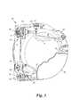
- a vehicle 1 with driver's cab 2 and chassis 3is shown in plan view.
- the vehicle 1carries a conventional tank system 4 with two LNG containers 5, 6; the second container 6 could also be a CNG container.
- the first container 5is mounted by means of support brackets 7 on the chassis 3 and has for refueling via fittings which are housed in a housing 8.
- one or more connecting line 9 of the second container 6are passed transversely through the chassis 3 and open in fittings that are installed in a second housing 10.
- the space in commercial vehiclesis very limited and the need of the second housing 10 reduces the space available for the first container 4 space considerably. Even if the two housings 8, 10 are mounted directly next to each other or combined to form a larger housing, this means only a small space saving.
- the inventionhas for its object to provide a tank system for a vehicle with double tank system, which makes better use of the existing space.
- a tank system of the aforementioned typewhich is characterized according to the invention in that the at least one armature of the second container is at least partially in a gusset which is between the first container and a smallest, the first Container circumscribed, imaginary cuboid is included.
- the inventionthus allows a much better utilization of the available space by fittings of the container, namely at least one of the fittings of the opposite container, in one of the interstices ("gusset"), which remain between the curves of a pressure vessels and a cuboid installation space , to be ordered.
- the elimination of the housing 10 in Fig. 1the container can be made longer, whereby the volume of entrained fuel can be significantly increased.
- connection line (s) of the fitting (s) of the second container in the region of the first containeris / are passed through said gusset, which further saves installation space.
- the connection line (s)can thereby e.g. follow the curvature of an end cap of the container.
- said gussetis that enclosed between the end cap and the parallelepiped ("cap wad"). Since containers for LNG are exposed to high pressures and CNG pressures, they often have a design with such dome-shaped end caps. According to the invention, this curved shape is utilized to accommodate the fittings of the second container at these bends.
- the first containeralso particularly preferably has one of the first opposing second dome-shaped end cap and at least one further fitting of at least one further connection line connected to the first container is located in the gusset which is enclosed between this second end cap and the parallelepiped.
- the fittingsare accessible at the two opposite end caps of the container, a particularly compact component is created, which can accommodate the fittings of both containers to save space.
- said gussetmay also be that enclosed between the jacket and the parallelepiped ( "coat gusset").
- the fitting (s)can / can be arranged along the container shell, without overhanging a cuboid installation space. Again, this allows the length of the first container to be increased without losing space elsewhere in the vehicle.
- At least one further fitting of at least one further connecting line connected to the first containermay preferably also be located in said jacket gusset.
- the fitting (s)may be carried by a separate carrier mountable on the chassis of the vehicle.
- the carriermay be fastened to the first container.
- the wearermay e.g. be designed as a housing that houses several valves at once.
- the supportmay be mounted on the end cap and equipped with a preferably D-shaped cover plate with side walls, which engages over the fitting (s).
- the fittingscan be accessible through an opening in a side wall.
- the cover plate with side wallsmay thus be attached as a cover module ("shroud") to the end cap.
- the straight side of the "D"is preferably on the side facing away from the vehicle chassis to align with a vehicle wall and so make the best use of the available space ,
- the supportmay be mounted on the jacket and provided with an L-shaped cover plate having side walls which engage over the fitting (s) passing through an opening in the cover plate can be accessible.
- the two containerscan be very close together or even be installed together under a single cover plate, which increases the refueling comfort.
- the tank system according to the inventionis suitable for all types of pressure tanks, be they LNG or CNG containers.
- the second containeris e.g. an LNG container and for him three connecting lines are provided, of which the first as a fitting a filling coupling, the second has a pressure gauge and the third a Ventan gleich with upstream manual valve.
- Thisallows all fittings necessary for an LNG container to be collectively accessible on the first container, e.g. in a common housing.
- the second containeris formed by one or preferably a bundle of CNG containers and for this purpose two connecting lines are provided, of which the first as a fitting has a filling coupling and the second one has a pressure indicator.
- a combined LNG and CNG tank systemcan be created when the first container is an LNG container.
- FIG. 1which shows the state of the art, reference is made to the introduction to the description, which in the description below the Fig. 2-5 same reference numerals to like components as in FIG Fig. 1 Respectively.
- the Fig. 2 and 3show a first embodiment according to the invention of the tank system 4 based on the first container 5 and the components installed thereon, wherein the second container 6 and the vehicle 1 are not shown for reasons of clarity.
- the first and second containers 5, 6are arranged at different locations, usually on opposite sides, of the chassis 3, for example on the driver's side and on the passenger's side.
- the second container 6could, for example, at the point or side, which is behind the driver's cab, be arranged transversely to the direction of travel, or at another location of the chassis.
- the first container 5is in this embodiment, an LNG container with a cylindrical shell 11 and two, for example, welded dome-shaped end caps 12, 13.
- the (in the Fig. 2 and 3 not shown) second container 6is, for example, also an LNG container and has (at least) a connecting line 9, which is at that point of the chassis 3, where the first container 5 is located, and there in a valve 14, for example, a refueling coupling, opens.
- the curvature of the end cap 12results in a gap or gusset 15a ("cap wrap") between the end cap 12 and a smallest possible, the first container 5 circumscribing, imaginary cuboid 16, which at the same time available to the vehicle 1 cuboid installation space for the Container 5 describes.
- the armature 14 of the second container 6is - at least partially - arranged in this gusset 15 a and is thus accessible from the vehicle side of the container 5 ago.
- the said connecting line 9 in the region of the first container 5can be passed through the gusset 15a, see Fig. 3 , By exploiting the cap wraps 15a for the - at least one - fitting 14 and its connecting line 9, a greater length and thus a larger volume of the first container 5 in comparison to Fig. 1 be achieved.
- the second container 6is an LNG container, this can in particular be a pressure indicator 17 on a connection line 18 and a vent connection 19 with an upstream manual valve 20 on a connecting line 21, in order to feed the second container 6 degas. If the second container 6 is a CNG container, a pressure indicator 17 is usually sufficient in addition to the refueling coupling 14.
- All fittings 14, 17, 19, 20can be positioned in the cap coiling 15a on a common (or a plurality of individual) mounted on the vehicle chassis 3 carrier (s) (in Fig. 3 not shown), or, as in Fig. 3 shown held by a support 22 which is mounted directly on the end cap 12.
- the carrier 22can be welded, screwed or glued to the end cap 12 or clamped onto it and / or the jacket 11 with a press fit.
- the carrier 22is - as in Fig. 3 shown in the form of approximately frame-like around the end cap 12 arranged side walls 23 formed with a removable or fixed cover plate 24, which together form a semi-open, the end cap 12 facing housing ("Shroud").
- openings 25, 26, 27, 28may be provided, via which the fittings 14, 17, 19, 20 are accessible for refueling.
- the openings 25, 26, 27, 28may be provided with removable closure lids (not shown).
- the cover plate 24 and the side walls 25 seen in the direction of the container longitudinal axis Lare approximately D-shaped. Alternatively, they could also be round or square, depending on the shape of the container 5 and the number or type of fittings 14, 17, 19, 20.
- the cover plate 24 and side walls 23can also be seen in the direction of the container longitudinal axis L aligned or . congruent be formed with the first container 5, for example, has a square container 5 with dome-shaped end caps 12, 13 a congruent square cover plate 24th
- the first container 5in turn has a set of fittings, such as a filling coupling 29, a pressure gauge (not shown) and a vent port 30 with manual valve 31 in the case of an LNG tank.
- the fittings 29, 30, 31 and their connecting linescan - mirror images of Fig. 3 - Are arranged in the opposite cap wraps 15 b between the other end cap 13 and the imaginary cuboid 16.
- the fittings 29, 30, 31 of the first container 5may be supported by another carrier 22 with optional side walls 32 and cover plate 33.
- the combination of container 5 with fittings 14, 17, 19, 20 of the second container 6 and its own fittings 29, 30, 31no greater length than the first container 5 itself, except for the thickness of the cover plates 24, 33rd ,
- the 4 and 5show an alternative embodiment in which some or all fittings 14, 17 (in the case of a CNG container 6) or 14, 17, 19, 20 (in the case of an LNG container 6) - at least partially - in one of the interspaces or Gussets 15c, 15d, 15e, 15f, which result between the (here: cylindrical) jacket 11 of the first container 5 and the imaginary cuboid 16 ("jacket gusset").
- gussets 15c-15eare distributed over the circumference of the jacket 11, and according to the 4 and 5 selected gusset 15c is located on the upper side facing away from the chassis of the shell 11, which allows a particularly easy access to the fittings 14, 17 (or optionally 19, 20).
- An accommodation of the fittings in one of the other three gussets 15d, 15e, 15fis also possible depending on the type and number of fittings.
- the valvescan also be distributed over two or more different jacket gussets.
- first container 5has a generally cylindrical, eg D-shaped, cross-section, there may also be less than four jacket gussets 15d-15f, eg only two jacket gussets on the round side of the "D". If the first container 5 has dome-shaped end caps 12, 13, said connecting line (s) 9, 18, 21 can also be passed from the jacket gusset 15c through the cap wraps 15a, 15b, as in FIG Fig. 5 shown to save even more space.
- the fittings 14, 17can be held again by a carrier (not shown) mounted on the vehicle chassis 3 or by a carrier 22 mounted on the casing 11.
- the carrier 22may be, for example, an L-shaped cover plate 34 with side walls 35, which engage over the fittings 14, 17 (or 19, 20) and form a semi-open, the shell 11 facing housing.
- the fittings 14, 17, 19, 20can be accessible again through openings in the cover plate 34.
- the first container 5in turn connecting lines 36, 37, 38, in said Faucets 29, 30, 31 and a pressure gauge 39 open.
- the fittings 29, 30, 31, 39 of the first container 5are arranged in the same jacket gusset 15c as the fittings 14, 17 (or 19, 20) of the second container 6, but can also be positioned in another of the jacket gussets 15d-15f , It is also possible that the fittings for the second container 6 in a jacket gussets 15c - 15f and the fittings for the first container 5 in a cap wraps 15a, 15b and vice versa.
- the fittings 29, 30, 31, 39 of the first container 5can be held again by a support 22 from an L-shaped cover plate 40 with side walls 41, or there is a common cover plate for all fittings 14, 17, 19, 20, 29, 30, 31, 39 used.
Landscapes
- Engineering & Computer Science (AREA)
- Life Sciences & Earth Sciences (AREA)
- Sustainable Development (AREA)
- Sustainable Energy (AREA)
- Chemical & Material Sciences (AREA)
- Combustion & Propulsion (AREA)
- Transportation (AREA)
- Mechanical Engineering (AREA)
- Cooling, Air Intake And Gas Exhaust, And Fuel Tank Arrangements In Propulsion Units (AREA)
Abstract
Translated fromGerman
Description
Translated fromGermanDie vorliegende Erfindung betrifft ein Tanksystem für ein Fahrzeug, umfassend einen ersten und einen zweiten Druckbehälter, die an verschiedenen Stellen eines Chassis des Fahrzeugs, insbesondere an gegenüberliegenden Seiten des Chassis, montierbar sind, wobei zumindest eine Anschlussleitung des zweiten Behälters zu jener Stelle des Chassis, an der sich der erste Behälter befindet, geführt ist und in einer dort zugänglichen Armatur mündet.The present invention relates to a tank system for a vehicle, comprising a first and a second pressure vessel, which are mountable at various locations of a chassis of the vehicle, in particular on opposite sides of the chassis, wherein at least one connecting line of the second container to that location of the chassis, at which the first container is located, is guided and opens into a fitting accessible there.
Aus dem Stand der Technik ist bekannt, erdgasbetriebene Nutzfahrzeuge mit Doppeltankanlagen auszustatten. Die beiden Tanks bzw. Behälter enthalten entweder verflüssigtes Erdgas (liquefied natural gas, LNG) bei Tiefsttemperaturen von etwa -160 °C bis -130 °C und vergleichsweise geringem Druck von etwa 1 bis 20 bar, oder stark komprimiertes Erdgas (compressed natural gas, CNG) unter hohem Druck von bis zu 200 bar. Auch Kombinationen von LNG- und CNG-Behältern sind im Einsatz. Zur Befüllung dieser Behälter sind eine Vielzahl aufwendiger und sperriger Armaturen notwendig: Für LNG-Behälter in der Regel zumindest eine Befüllkupplung, eine Druckanzeige und ein Ventanschluss mit Handventil zur Entgasung des Behälters, und für CNG-Behälter zumindest eine Befüllkupplung und eine Druckanzeige. Die Armaturen der Behälter werden nach dem Stand der Technik jeweils in Gehäusen untergebracht, welche jedoch viel Platz einnehmen.
In
Der Bauraum in Nutzfahrzeugen ist jedoch stark begrenzt und die Notwendigkeit des zweiten Gehäuses 10 verringert den für den ersten Behälter 4 zur Verfügung stehenden Bauraum beträchtlich. Selbst wenn die beiden Gehäuse 8, 10 direkt nebeneinander montiert bzw. zu einem größeren Gehäuse vereint werden, bedeutet dies nur eine geringe Bauraumeinsparung.However, the space in commercial vehicles is very limited and the need of the
Die Erfindung setzt sich zum Ziel, ein Tanksystem für ein Fahrzeug mit Doppeltankanlage zu schaffen, das den bestehenden Bauraum besser ausnutzt.The invention has for its object to provide a tank system for a vehicle with double tank system, which makes better use of the existing space.
Dieses Ziel wird mit einem Tanksystem der einleitend genannten Art erreicht, das sich gemäß der Erfindung dadurch auszeichnet, dass sich die zumindest eine Armatur des zweiten Behälters zumindest teilweise in einem Zwickel befindet, der zwischen dem ersten Behälter und einem kleinstmöglichen, den ersten Behälter umschreibenden, gedachten Quader eingeschlossen ist.This object is achieved with a tank system of the aforementioned type, which is characterized according to the invention in that the at least one armature of the second container is at least partially in a gusset which is between the first container and a smallest, the first Container circumscribed, imaginary cuboid is included.
Die Erfindung ermöglicht damit eine wesentlich bessere Ausnutzung des zur Verfügung stehenden Bauraums, indem Armaturen des Behälters, und zwar zumindest eine der Armaturen des gegenüberliegenden Behälters, in einem der Zwischenräume ("Zwickel"), die zwischen den Rundungen eines Druckbehältern und einem quaderförmigen Einbauraum verbleiben, angeordnet werden. Durch den solcherart eingesparten Platz, dem Wegfall des Gehäuses 10 in
Bevorzugt wird/werden auch die Anschlussleitung(en) der Armatur(en) des zweiten Behälters im Bereich des ersten Behälters durch den genannten Zwickel hindurchgeführt, was weiter Bauraum einspart. Die Anschlussleitung(en) kann/können dabei z.B. der Krümmung einer Endkappe des Behälters folgen.Preferably, the connecting line (s) of the fitting (s) of the second container in the region of the first container is / are passed through said gusset, which further saves installation space. The connection line (s) can thereby e.g. follow the curvature of an end cap of the container.
In einer ersten Ausführungsform der Erfindung, in welcher der erste Behälter eine erste kalottenförmige Endkappe hat, ist der genannte Zwickel jener, der zwischen der Endkappe und dem Quader eingeschlossen ist ("Kappenzwickel"). Da Behälter für LNG hohen und für CNG höchsten Drücken ausgesetzt sind, haben diese oft eine Bauform mit solch kalottenförmigen Endkappen. Erfindungsgemäß wird diese gekrümmte Form ausgenutzt, um die Armaturen des zweiten Behälters an diesen Krümmungen unterzubringen.In a first embodiment of the invention in which the first container has a first dome-shaped end cap, said gusset is that enclosed between the end cap and the parallelepiped ("cap wad"). Since containers for LNG are exposed to high pressures and CNG pressures, they often have a design with such dome-shaped end caps. According to the invention, this curved shape is utilized to accommodate the fittings of the second container at these bends.
Besonders bevorzugt hat der erste Behälter in dieser Ausführungsform auch eine der ersten gegenüberliegende zweite kalottenförmige Endkappe und zumindest eine weitere Armatur zumindest einer mit dem ersten Behälter verbundenen weiteren Anschlussleitung befindet sich in dem Zwickel, der zwischen dieser zweiten Endkappe und dem genannten Quader eingeschlossen ist. Indem die Armaturen an den beiden gegenüberliegenden Endkappen des Behälters zugänglich sind, wird ein besonders kompaktes Bauelement geschaffen, das die Armaturen beider Behälter platzsparend unterbringen kann.In this embodiment, the first container also particularly preferably has one of the first opposing second dome-shaped end cap and at least one further fitting of at least one further connection line connected to the first container is located in the gusset which is enclosed between this second end cap and the parallelepiped. By the fittings are accessible at the two opposite end caps of the container, a particularly compact component is created, which can accommodate the fittings of both containers to save space.
In einer zweiten Ausführungsform der Erfindung, in welcher der erste Behälter einen allgemein-zylindrischen, bevorzugt kreiszylindrischen, Mantel hat, wie es bei Druckbehältern häufig der Fall ist, kann der genannte Zwickel aber auch jener sein, der zwischen dem Mantel und dem Quader eingeschlossen ist ("Mantelzwickel"). Die Armatur(en) kann/können so auch entlang des Behältermantels angeordnet werden, ohne einen quaderförmigen Einbauraum zu überragen. Abermals kann damit die Länge des ersten Behälters vergrößert werden, ohne an einer anderen Stelle des Fahrzeugs an Platz zu verlieren.In a second embodiment of the invention, in which the first container has a generally cylindrical, preferably circular cylindrical, jacket, as is often the case with pressure vessels, said gusset may also be that enclosed between the jacket and the parallelepiped ( "coat gusset"). The fitting (s) can / can be arranged along the container shell, without overhanging a cuboid installation space. Again, this allows the length of the first container to be increased without losing space elsewhere in the vehicle.
Bevorzugt kann sich dabei auch zumindest eine weitere Armatur zumindest einer mit dem ersten Behälter verbundenen weiteren Anschlussleitung in dem genannten Mantelzwickel befinden. Dies schafft eine Lösung, bei der die Armaturen sowohl des ersten als auch des zweiten Behälters an dessen Längsseite angebracht sind, um die Länge des ersten Behälters zu maximieren. Dies ermöglicht zudem Ausführungsformen, bei denen alle Armaturen des ersten und zweiten Behälters in einem gemeinsamen Gehäuse untergebracht sind.In this case, at least one further fitting of at least one further connecting line connected to the first container may preferably also be located in said jacket gusset. This provides a solution in which the fittings of both the first and second containers are mounted on its longitudinal side to maximize the length of the first container. This also allows embodiments in which all fittings of the first and second containers are housed in a common housing.
Um die Armatur (en) unabhängig vom Tank zu fixieren, kann bzw. können diese von einem gesonderten, am Fahrzeugchassis montierbaren Träger getragen sein. Alternativ ist es jedoch auch möglich, den Träger am ersten Behälter zu befestigten. In beiden Fällen kann der Träger z.B. als Gehäuse ausgebildet sein, das gleich mehrere Armaturen beherbergt.In order to fix the fitting (s) independently of the tank, they may be carried by a separate carrier mountable on the chassis of the vehicle. Alternatively, however, it is also possible to fasten the carrier to the first container. In both cases the wearer may e.g. be designed as a housing that houses several valves at once.
Ist/sind die Armatur(en) an einer Endkappe des ersten Behälters zugänglich, kann der Träger an der Endkappe montiert und mit einer bevorzugt D-förmigen Abdeckplatte mit Seitenwänden ausgestattet sein, die die Armatur(en) übergreift. Die Armaturen können dabei durch eine Öffnung in einer Seitenwand zugänglich sein. Die Abdeckplatte mit Seitenwänden kann so als ein Abdeckmodul ("Shroud") an der Endkappe angebracht werden. Bei einer D-förmigen Abdeckplatte, die optimal an Behälter mit D-förmigem Querschnitt angepasst ist, liegt die gerade Seite des "D" bevorzugt an der dem Fahrzeugchassis abgewandten Seite, um mit einer Fahrzeugwand zu fluchten und so den zur Verfügung stehenden Bauraum bestmöglich auszunutzen.Is / are the fitting (s) accessible to an end cap of the first container, the support may be mounted on the end cap and equipped with a preferably D-shaped cover plate with side walls, which engages over the fitting (s). The fittings can be accessible through an opening in a side wall. The cover plate with side walls may thus be attached as a cover module ("shroud") to the end cap. In a D-shaped cover plate, which is optimally adapted to containers with a D-shaped cross section, the straight side of the "D" is preferably on the side facing away from the vehicle chassis to align with a vehicle wall and so make the best use of the available space ,
Ist/sind die Armatur(en) hingegen am Mantel des ersten Behälters zugänglich, kann der Träger am Mantel montiert und mit einer L-förmigen Abdeckplatte mit Seitenwänden ausgestattet sein, die die Armatur(en) übergreifen, welche dabei durch eine Öffnung in der Abdeckplatte zugänglich sein kann/können. Die beiden Behälter können dabei sehr eng nebeneinander oder sogar gemeinsam unter einer einzigen Abdeckplatte verbaut werden, was den Betankungskomfort erhöht.On the other hand, if the fitting (s) are accessible on the shell of the first container, the support may be mounted on the jacket and provided with an L-shaped cover plate having side walls which engage over the fitting (s) passing through an opening in the cover plate can be accessible. The two containers can be very close together or even be installed together under a single cover plate, which increases the refueling comfort.
Das erfindungsgemäße Tanksystem eignet sich für alle Arten von Drucktanks, seien sie LNG- oder CNG-Behälter. In einer Ausführungsform der Erfindung ist der zweite Behälter z.B. ein LNG-Behälter und für ihn sind drei Anschlussleitungen vorgesehen, von denen die erste als Armatur eine Befüllkupplung, die zweite eine Druckanzeige und die dritte einen Ventanschluss mit vorgeschaltetem Handventil hat. Dies ermöglicht, dass alle für einen LNG-Behälter notwendigen Armaturen gemeinsam am ersten Behälter zugänglich sind, z.B. in einem gemeinsamen Gehäuse. Weiters kann damit bevorzugt ein Doppel-LNG-Tanksystem geschaffen, wenn auch der erste Behälter als LNG-Behälter ausgebildet ist.The tank system according to the invention is suitable for all types of pressure tanks, be they LNG or CNG containers. In an embodiment of the invention, the second container is e.g. an LNG container and for him three connecting lines are provided, of which the first as a fitting a filling coupling, the second has a pressure gauge and the third a Ventanschluss with upstream manual valve. This allows all fittings necessary for an LNG container to be collectively accessible on the first container, e.g. in a common housing. Furthermore, it is thus possible to create a double-LNG tank system, although the first container is designed as an LNG container.
Alternativ ist der zweite Behälter durch einen oder bevorzugt ein Bündel von CNG-Behälter gebildet und dafür sind zwei Anschlussleitungen vorgesehen, von denen die erste als Armatur eine Befüllkupplung und die zweite eine Druckanzeige hat. Damit kann beispielsweise ein kombiniertes LNG- und CNG-Tanksystem geschaffen werden, wenn der erste Behälter ein LNG-Behälter ist.Alternatively, the second container is formed by one or preferably a bundle of CNG containers and for this purpose two connecting lines are provided, of which the first as a fitting has a filling coupling and the second one has a pressure indicator. Thus, for example, a combined LNG and CNG tank system can be created when the first container is an LNG container.
Die Erfindung wird nachfolgend anhand von in den beigeschlossenen Zeichnungen dargestellten Ausführungsbeispielen näher erläutert. In den Zeichnungen zeigen:
Fig. 1 ein Tanksystem für ein Fahrzeug gemäß dem Stand der Technik in einer Draufsicht;Fig. 2 eine erste Ausführungsform eines Tanksystems gemäß der Erfindung in einer schematischen Seitenansicht;Fig. 3 das Tanksystem vonFig. 2 in einer ausschnittsweisen und teilweise aufgebrochenen Perspektivansicht;Fig. 4 eine zweite Ausführungsform eines Tanksystems der Erfindung in einer schematischen Stirnansicht; undFig. 5 das Tanksystem vonFig. 4 in einer ausschnittsweisen Perspektivansicht.
Fig. 1 a tank system for a vehicle according to the prior art in a plan view;Fig. 2 a first embodiment of a tank system according to the invention in a schematic side view;Fig. 3 the tank system ofFig. 2 in a partial and partially broken perspective view;Fig. 4 a second embodiment of a tank system of the invention in a schematic end view; andFig. 5 the tank system ofFig. 4 in a fragmentary perspective view.
Bezüglich
Die
Der erste Behälter 5 ist in dieser Ausführungsform ein LNG-Behälter mit einem zylindrischen Mantel 11 und zwei z.B. angeschweißten kalottenförmigen Endkappen 12, 13. Der (in den
Durch die Krümmung der Endkappe 12 ergibt sich ein Zwischenraum bzw. Zwickel 15a ("Kappenzwickel") zwischen der Endkappe 12 und einem kleinstmöglichen, den ersten Behälter 5 umschreibenden, gedachten Quader 16, welcher gleichzeitig den am Fahrzeug 1 zur Verfügung stehenden quaderförmigen Einbauraum für den Behälter 5 beschreibt. Die Armatur 14 des zweiten Behälters 6 wird - zumindest teilweise - in diesem Zwickel 15a angeordnet und ist damit von der Fahrzeugseite des Behälters 5 her zugänglich. Weiters kann auch die genannte Anschlussleitung 9 im Bereich des ersten Behälters 5 durch den Zwickel 15a hindurchgeführt werden, siehe
Wie in
Alle Armaturen 14, 17, 19, 20 können im Kappenzwickel 15a an einem gemeinsamen (oder mehreren einzelnen) am Fahrzeugchassis 3 montierten Träger(n) positioniert werden (in
Bevorzugt ist der Träger 22 - wie in
In dem in
Wie in
Die
Bei einem kreiszylindrischen Mantel 11 ergeben sich vier Mantelzwickel 15c - 15e über den Umfang des Mantels 11 verteilt, und der gemäß den
Wenn der erste Behälter 5 einen allgemein-zylindrischen, z.B. D-förmigen Querschnitt hat, kann es auch weniger als vier Mantelzwickel 15d - 15f geben, z.B. nur zwei Mantelzwickel auf der runden Seite des "D". Hat der erste Behälter 5 kalottenförmige Endkappen 12, 13, können die genannte(n) Anschlussleitung(en) 9, 18, 21 vom Mantelzwickel 15c auch durch die Kappenzwickel 15a, 15b hindurchgeführt werden, wie in
Bei der Ausführungsform der
Wie in
Die Erfindung ist demgemäß nicht auf die dargestellten Ausführungsformen beschränkt, sondern umfasst alle Varianten, Modifikationen und Kombinationen, die in den Rahmen der angeschlossenen Ansprüche fallen.The invention is therefore not limited to the illustrated embodiments, but includes all variants, modifications, and combinations that fall within the scope of the appended claims.
Claims (12)
Translated fromGermandadurch gekennzeichnet,
dass sich die Armatur (14, 17, 19, 20) zumindest teilweise in einem Zwickel (15a - 15f) befindet, der zwischen dem ersten Behälter (5) und dem kleinstmöglichen, den ersten Behälter (5) umschreibenden, gedachten Quader (16) eingeschlossen ist.Tank system for a vehicle (1), comprising a first and a second pressure vessel (5, 6) which are mountable at various locations of a chassis (3) of the vehicle (1), in particular on opposite sides of the chassis (3) at least one connecting line (9, 18, 21) of the second container (6) to that point of the chassis (3) at which the first container (5) is located, and in an accessible there fitting (14, 17, 19 , 20),
characterized,
in that the fitting (14, 17, 19, 20) is located at least partially in a gusset (15a - 15f) which is arranged between the first container (5) and the smallest imaginary cuboid (16) circumscribing the first container (5). is included.
Priority Applications (2)
| Application Number | Priority Date | Filing Date | Title |
|---|---|---|---|
| EP15167128.6AEP3093178B1 (en) | 2015-05-11 | 2015-05-11 | Tank system for a vehicle |
| ES15167128.6TES2664099T3 (en) | 2015-05-11 | 2015-05-11 | Deposit system for a vehicle |
Applications Claiming Priority (1)
| Application Number | Priority Date | Filing Date | Title |
|---|---|---|---|
| EP15167128.6AEP3093178B1 (en) | 2015-05-11 | 2015-05-11 | Tank system for a vehicle |
Publications (2)
| Publication Number | Publication Date |
|---|---|
| EP3093178A1true EP3093178A1 (en) | 2016-11-16 |
| EP3093178B1 EP3093178B1 (en) | 2017-12-27 |
Family
ID=53054986
Family Applications (1)
| Application Number | Title | Priority Date | Filing Date |
|---|---|---|---|
| EP15167128.6AActiveEP3093178B1 (en) | 2015-05-11 | 2015-05-11 | Tank system for a vehicle |
Country Status (2)
| Country | Link |
|---|---|
| EP (1) | EP3093178B1 (en) |
| ES (1) | ES2664099T3 (en) |
Cited By (7)
| Publication number | Priority date | Publication date | Assignee | Title |
|---|---|---|---|---|
| WO2018170486A1 (en)* | 2017-03-17 | 2018-09-20 | Chart Inc. | Space conserving integrated cryogenic fluid delivery system |
| IT201700114588A1 (en)* | 2017-10-11 | 2019-04-11 | Iveco France Sas | GAS VEHICLE FOR PUBLIC TRANSPORT |
| EP3470252A1 (en)* | 2017-10-10 | 2019-04-17 | Salzburger Aluminium Aktiengesellschaft | Tank system for a vehicle |
| WO2021102489A1 (en)* | 2019-11-29 | 2021-06-03 | Cryoshelter Gmbh | System comprising at least two cryogenic vessels for providing a fluid |
| US20240051384A1 (en)* | 2021-04-01 | 2024-02-15 | Cryoshelter LH2 GmbH | Mounting system for fastening a cryogenic container onto a vehicle frame |
| US20240183499A1 (en)* | 2021-04-01 | 2024-06-06 | Cryoshelter Gmbh | A vehicle with a cryogenic container and efficient routing of the connection line |
| WO2024115894A3 (en)* | 2022-12-01 | 2024-07-11 | J.C. Bamford Excavators Limited | A storage system for a gaseous fuel |
Citations (4)
| Publication number | Priority date | Publication date | Assignee | Title |
|---|---|---|---|---|
| US5658013A (en)* | 1995-09-20 | 1997-08-19 | The Babcock & Wilcox Company | Fuel tank for vehicles for holding and dispensing both a liquid and gaseous fuel therein |
| EP2287458A2 (en)* | 2009-08-21 | 2011-02-23 | GM Global Technology Operations, Inc. | Method of detecting at least one malfunctioning high-pressure gas tank |
| US20140069972A1 (en)* | 2012-09-10 | 2014-03-13 | Alternative Fuel Containers, LLC (KSR Technologies Co.) | Method and apparatus for mounting cng/ang tanks to heavy trucks |
| US20140137953A1 (en)* | 2012-11-21 | 2014-05-22 | Trilogy Engineered Solutions, LLC | Methods and systems for compressed natural gas (cng) |
- 2015
- 2015-05-11EPEP15167128.6Apatent/EP3093178B1/enactiveActive
- 2015-05-11ESES15167128.6Tpatent/ES2664099T3/enactiveActive
Patent Citations (4)
| Publication number | Priority date | Publication date | Assignee | Title |
|---|---|---|---|---|
| US5658013A (en)* | 1995-09-20 | 1997-08-19 | The Babcock & Wilcox Company | Fuel tank for vehicles for holding and dispensing both a liquid and gaseous fuel therein |
| EP2287458A2 (en)* | 2009-08-21 | 2011-02-23 | GM Global Technology Operations, Inc. | Method of detecting at least one malfunctioning high-pressure gas tank |
| US20140069972A1 (en)* | 2012-09-10 | 2014-03-13 | Alternative Fuel Containers, LLC (KSR Technologies Co.) | Method and apparatus for mounting cng/ang tanks to heavy trucks |
| US20140137953A1 (en)* | 2012-11-21 | 2014-05-22 | Trilogy Engineered Solutions, LLC | Methods and systems for compressed natural gas (cng) |
Cited By (12)
| Publication number | Priority date | Publication date | Assignee | Title |
|---|---|---|---|---|
| WO2018170486A1 (en)* | 2017-03-17 | 2018-09-20 | Chart Inc. | Space conserving integrated cryogenic fluid delivery system |
| US20180266629A1 (en)* | 2017-03-17 | 2018-09-20 | Chart Inc. | Space Conserving Integrated Cryogenic Fluid Delivery System |
| EP3376013B1 (en)* | 2017-03-17 | 2021-05-05 | Chart Inc. | Space conserving integrated cryogenic fluid delivery system |
| US11118736B2 (en) | 2017-03-17 | 2021-09-14 | Chart Inc. | Space conserving integrated cryogenic fluid delivery system |
| EP3470252A1 (en)* | 2017-10-10 | 2019-04-17 | Salzburger Aluminium Aktiengesellschaft | Tank system for a vehicle |
| IT201700114588A1 (en)* | 2017-10-11 | 2019-04-11 | Iveco France Sas | GAS VEHICLE FOR PUBLIC TRANSPORT |
| WO2021102489A1 (en)* | 2019-11-29 | 2021-06-03 | Cryoshelter Gmbh | System comprising at least two cryogenic vessels for providing a fluid |
| US12331891B2 (en) | 2019-11-29 | 2025-06-17 | Cryoshelter LH2 GmbH | System having at least two cryogenic containers for providing a fluid |
| US20240051384A1 (en)* | 2021-04-01 | 2024-02-15 | Cryoshelter LH2 GmbH | Mounting system for fastening a cryogenic container onto a vehicle frame |
| US20240183499A1 (en)* | 2021-04-01 | 2024-06-06 | Cryoshelter Gmbh | A vehicle with a cryogenic container and efficient routing of the connection line |
| US12337678B2 (en)* | 2021-04-01 | 2025-06-24 | Cryoshelter LH2 GmbH | Mounting system for fastening a cryogenic container onto a vehicle frame |
| WO2024115894A3 (en)* | 2022-12-01 | 2024-07-11 | J.C. Bamford Excavators Limited | A storage system for a gaseous fuel |
Also Published As
| Publication number | Publication date |
|---|---|
| EP3093178B1 (en) | 2017-12-27 |
| ES2664099T3 (en) | 2018-04-18 |
Similar Documents
| Publication | Publication Date | Title |
|---|---|---|
| EP3093178B1 (en) | Tank system for a vehicle | |
| DE102018119087A1 (en) | Vehicle base structure | |
| DE102018000756A1 (en) | Compressed gas tank and compressed gas storage | |
| EP2148127A2 (en) | Storage device for compressed media and method for filling the tank of vehicles | |
| EP3121505A1 (en) | Device for holding a cryofluid | |
| EP3121051B1 (en) | Tank system for a vehicle | |
| WO2021156349A1 (en) | Pressure vessel assembly and pressure vessel system | |
| WO2014127935A1 (en) | Pressure vessel comprising a heat exchanger for a cryogenically stored medium | |
| DE102014206370A1 (en) | Pressure vessel with an inner and an outer container | |
| DE102009039079A1 (en) | Tank arrangement for motor vehicle, has compressed gas-operated fuel cell and electric motor, where multiple pressure containers are provided for receiving pressure gas | |
| DE102020108176A1 (en) | Fuel supply system and motor vehicle | |
| EP3121050A1 (en) | Tank system for a vehicle | |
| EP3470252B1 (en) | Tank system for a vehicle | |
| DE102007049458A1 (en) | Compressed gas installation for storing a gas comprises compressed gas containers for holding a pressurized gas within a gas volume, a liquid container for holding an equalization liquid and a pump unit connected to liquid openings | |
| DE202018105794U1 (en) | Gas powered vehicle for public transport | |
| DE102017208419A1 (en) | Refueling arrangement of a vehicle | |
| DE437155C (en) | Device for storing gas under pressure | |
| WO2021026582A1 (en) | Cryogenic vessel and secondary system for filling and venting the cryogenic vessel | |
| EP4025447B1 (en) | Fastening system for a cryogenic container having a connection protruding out of the container shell | |
| EP3121090B1 (en) | Pneumatic spring assembly for railway vehicle and railway vehicle with pneumatic spring assembly | |
| DE102022129587A1 (en) | Mounting device for holding tank bottles | |
| WO2022204744A1 (en) | Mounting system for fastening a cryogenic container to a vehicle frame | |
| DE102013106532A1 (en) | Gas container with several pressure vessels | |
| EP4313652B1 (en) | Vehicle with cryogenic container and efficient routing of the connection line | |
| DE102010050576B4 (en) | A collection unit for dispensing liquids from at least one tank and tanker |
Legal Events
| Date | Code | Title | Description |
|---|---|---|---|
| PUAI | Public reference made under article 153(3) epc to a published international application that has entered the european phase | Free format text:ORIGINAL CODE: 0009012 | |
| AK | Designated contracting states | Kind code of ref document:A1 Designated state(s):AL AT BE BG CH CY CZ DE DK EE ES FI FR GB GR HR HU IE IS IT LI LT LU LV MC MK MT NL NO PL PT RO RS SE SI SK SM TR | |
| AX | Request for extension of the european patent | Extension state:BA ME | |
| 17P | Request for examination filed | Effective date:20170421 | |
| RBV | Designated contracting states (corrected) | Designated state(s):AL AT BE BG CH CY CZ DE DK EE ES FI FR GB GR HR HU IE IS IT LI LT LU LV MC MK MT NL NO PL PT RO RS SE SI SK SM TR | |
| GRAP | Despatch of communication of intention to grant a patent | Free format text:ORIGINAL CODE: EPIDOSNIGR1 | |
| RIC1 | Information provided on ipc code assigned before grant | Ipc:B60K 15/063 20060101ALI20170707BHEP Ipc:B60K 15/07 20060101AFI20170707BHEP | |
| INTG | Intention to grant announced | Effective date:20170803 | |
| GRAA | (expected) grant | Free format text:ORIGINAL CODE: 0009210 | |
| GRAS | Grant fee paid | Free format text:ORIGINAL CODE: EPIDOSNIGR3 | |
| AK | Designated contracting states | Kind code of ref document:B1 Designated state(s):AL AT BE BG CH CY CZ DE DK EE ES FI FR GB GR HR HU IE IS IT LI LT LU LV MC MK MT NL NO PL PT RO RS SE SI SK SM TR | |
| REG | Reference to a national code | Ref country code:GB Ref legal event code:FG4D Free format text:NOT ENGLISH | |
| REG | Reference to a national code | Ref country code:CH Ref legal event code:EP | |
| REG | Reference to a national code | Ref country code:AT Ref legal event code:REF Ref document number:957970 Country of ref document:AT Kind code of ref document:T Effective date:20180115 | |
| REG | Reference to a national code | Ref country code:IE Ref legal event code:FG4D Free format text:LANGUAGE OF EP DOCUMENT: GERMAN | |
| REG | Reference to a national code | Ref country code:DE Ref legal event code:R096 Ref document number:502015002667 Country of ref document:DE | |
| REG | Reference to a national code | Ref country code:NL Ref legal event code:FP | |
| REG | Reference to a national code | Ref country code:CH Ref legal event code:NV Representative=s name:KAMINSKI HARMANN PATENTANWAELTE AG, LI | |
| REG | Reference to a national code | Ref country code:SE Ref legal event code:TRGR | |
| REG | Reference to a national code | Ref country code:CH Ref legal event code:NV Representative=s name:KAMINSKI HARMANN PATENTANWAELTE AG, CH Ref country code:CH Ref legal event code:PK Free format text:KORREKTUR DER VERTRETERADRESSE. | |
| REG | Reference to a national code | Ref country code:ES Ref legal event code:FG2A Ref document number:2664099 Country of ref document:ES Kind code of ref document:T3 Effective date:20180418 | |
| PG25 | Lapsed in a contracting state [announced via postgrant information from national office to epo] | Ref country code:NO Free format text:LAPSE BECAUSE OF FAILURE TO SUBMIT A TRANSLATION OF THE DESCRIPTION OR TO PAY THE FEE WITHIN THE PRESCRIBED TIME-LIMIT Effective date:20180327 Ref country code:FI Free format text:LAPSE BECAUSE OF FAILURE TO SUBMIT A TRANSLATION OF THE DESCRIPTION OR TO PAY THE FEE WITHIN THE PRESCRIBED TIME-LIMIT Effective date:20171227 Ref country code:LT Free format text:LAPSE BECAUSE OF FAILURE TO SUBMIT A TRANSLATION OF THE DESCRIPTION OR TO PAY THE FEE WITHIN THE PRESCRIBED TIME-LIMIT Effective date:20171227 | |
| REG | Reference to a national code | Ref country code:LT Ref legal event code:MG4D | |
| REG | Reference to a national code | Ref country code:FR Ref legal event code:PLFP Year of fee payment:4 | |
| PG25 | Lapsed in a contracting state [announced via postgrant information from national office to epo] | Ref country code:GR Free format text:LAPSE BECAUSE OF FAILURE TO SUBMIT A TRANSLATION OF THE DESCRIPTION OR TO PAY THE FEE WITHIN THE PRESCRIBED TIME-LIMIT Effective date:20180328 Ref country code:HR Free format text:LAPSE BECAUSE OF FAILURE TO SUBMIT A TRANSLATION OF THE DESCRIPTION OR TO PAY THE FEE WITHIN THE PRESCRIBED TIME-LIMIT Effective date:20171227 Ref country code:RS Free format text:LAPSE BECAUSE OF FAILURE TO SUBMIT A TRANSLATION OF THE DESCRIPTION OR TO PAY THE FEE WITHIN THE PRESCRIBED TIME-LIMIT Effective date:20171227 Ref country code:BG Free format text:LAPSE BECAUSE OF FAILURE TO SUBMIT A TRANSLATION OF THE DESCRIPTION OR TO PAY THE FEE WITHIN THE PRESCRIBED TIME-LIMIT Effective date:20180327 Ref country code:LV Free format text:LAPSE BECAUSE OF FAILURE TO SUBMIT A TRANSLATION OF THE DESCRIPTION OR TO PAY THE FEE WITHIN THE PRESCRIBED TIME-LIMIT Effective date:20171227 | |
| PG25 | Lapsed in a contracting state [announced via postgrant information from national office to epo] | Ref country code:CY Free format text:LAPSE BECAUSE OF FAILURE TO SUBMIT A TRANSLATION OF THE DESCRIPTION OR TO PAY THE FEE WITHIN THE PRESCRIBED TIME-LIMIT Effective date:20171227 Ref country code:EE Free format text:LAPSE BECAUSE OF FAILURE TO SUBMIT A TRANSLATION OF THE DESCRIPTION OR TO PAY THE FEE WITHIN THE PRESCRIBED TIME-LIMIT Effective date:20171227 Ref country code:CZ Free format text:LAPSE BECAUSE OF FAILURE TO SUBMIT A TRANSLATION OF THE DESCRIPTION OR TO PAY THE FEE WITHIN THE PRESCRIBED TIME-LIMIT Effective date:20171227 Ref country code:SK Free format text:LAPSE BECAUSE OF FAILURE TO SUBMIT A TRANSLATION OF THE DESCRIPTION OR TO PAY THE FEE WITHIN THE PRESCRIBED TIME-LIMIT Effective date:20171227 | |
| PG25 | Lapsed in a contracting state [announced via postgrant information from national office to epo] | Ref country code:PL Free format text:LAPSE BECAUSE OF FAILURE TO SUBMIT A TRANSLATION OF THE DESCRIPTION OR TO PAY THE FEE WITHIN THE PRESCRIBED TIME-LIMIT Effective date:20171227 Ref country code:SM Free format text:LAPSE BECAUSE OF FAILURE TO SUBMIT A TRANSLATION OF THE DESCRIPTION OR TO PAY THE FEE WITHIN THE PRESCRIBED TIME-LIMIT Effective date:20171227 Ref country code:IS Free format text:LAPSE BECAUSE OF FAILURE TO SUBMIT A TRANSLATION OF THE DESCRIPTION OR TO PAY THE FEE WITHIN THE PRESCRIBED TIME-LIMIT Effective date:20180427 | |
| PG25 | Lapsed in a contracting state [announced via postgrant information from national office to epo] | Ref country code:MT Free format text:LAPSE BECAUSE OF FAILURE TO SUBMIT A TRANSLATION OF THE DESCRIPTION OR TO PAY THE FEE WITHIN THE PRESCRIBED TIME-LIMIT Effective date:20171227 | |
| REG | Reference to a national code | Ref country code:DE Ref legal event code:R097 Ref document number:502015002667 Country of ref document:DE | |
| PLBE | No opposition filed within time limit | Free format text:ORIGINAL CODE: 0009261 | |
| STAA | Information on the status of an ep patent application or granted ep patent | Free format text:STATUS: NO OPPOSITION FILED WITHIN TIME LIMIT | |
| PG25 | Lapsed in a contracting state [announced via postgrant information from national office to epo] | Ref country code:DK Free format text:LAPSE BECAUSE OF FAILURE TO SUBMIT A TRANSLATION OF THE DESCRIPTION OR TO PAY THE FEE WITHIN THE PRESCRIBED TIME-LIMIT Effective date:20171227 | |
| 26N | No opposition filed | Effective date:20180928 | |
| PG25 | Lapsed in a contracting state [announced via postgrant information from national office to epo] | Ref country code:SI Free format text:LAPSE BECAUSE OF FAILURE TO SUBMIT A TRANSLATION OF THE DESCRIPTION OR TO PAY THE FEE WITHIN THE PRESCRIBED TIME-LIMIT Effective date:20171227 | |
| PGFP | Annual fee paid to national office [announced via postgrant information from national office to epo] | Ref country code:LU Payment date:20190521 Year of fee payment:5 | |
| PGFP | Annual fee paid to national office [announced via postgrant information from national office to epo] | Ref country code:DE Payment date:20190626 Year of fee payment:16 | |
| PGFP | Annual fee paid to national office [announced via postgrant information from national office to epo] | Ref country code:CH Payment date:20190523 Year of fee payment:5 | |
| PGFP | Annual fee paid to national office [announced via postgrant information from national office to epo] | Ref country code:GB Payment date:20190523 Year of fee payment:5 | |
| PG25 | Lapsed in a contracting state [announced via postgrant information from national office to epo] | Ref country code:TR Free format text:LAPSE BECAUSE OF FAILURE TO SUBMIT A TRANSLATION OF THE DESCRIPTION OR TO PAY THE FEE WITHIN THE PRESCRIBED TIME-LIMIT Effective date:20171227 | |
| PG25 | Lapsed in a contracting state [announced via postgrant information from national office to epo] | Ref country code:PT Free format text:LAPSE BECAUSE OF FAILURE TO SUBMIT A TRANSLATION OF THE DESCRIPTION OR TO PAY THE FEE WITHIN THE PRESCRIBED TIME-LIMIT Effective date:20171227 | |
| PG25 | Lapsed in a contracting state [announced via postgrant information from national office to epo] | Ref country code:RO Free format text:LAPSE BECAUSE OF FAILURE TO SUBMIT A TRANSLATION OF THE DESCRIPTION OR TO PAY THE FEE WITHIN THE PRESCRIBED TIME-LIMIT Effective date:20171227 Ref country code:HU Free format text:LAPSE BECAUSE OF FAILURE TO SUBMIT A TRANSLATION OF THE DESCRIPTION OR TO PAY THE FEE WITHIN THE PRESCRIBED TIME-LIMIT; INVALID AB INITIO Effective date:20150511 Ref country code:MK Free format text:LAPSE BECAUSE OF NON-PAYMENT OF DUE FEES Effective date:20171227 | |
| PG25 | Lapsed in a contracting state [announced via postgrant information from national office to epo] | Ref country code:AL Free format text:LAPSE BECAUSE OF FAILURE TO SUBMIT A TRANSLATION OF THE DESCRIPTION OR TO PAY THE FEE WITHIN THE PRESCRIBED TIME-LIMIT Effective date:20171227 | |
| PG25 | Lapsed in a contracting state [announced via postgrant information from national office to epo] | Ref country code:LI Free format text:LAPSE BECAUSE OF NON-PAYMENT OF DUE FEES Effective date:20200531 Ref country code:CH Free format text:LAPSE BECAUSE OF NON-PAYMENT OF DUE FEES Effective date:20200531 Ref country code:MC Free format text:LAPSE BECAUSE OF NON-PAYMENT OF DUE FEES Effective date:20200602 | |
| REG | Reference to a national code | Ref country code:BE Ref legal event code:MM Effective date:20200531 | |
| GBPC | Gb: european patent ceased through non-payment of renewal fee | Effective date:20200511 | |
| PG25 | Lapsed in a contracting state [announced via postgrant information from national office to epo] | Ref country code:LU Free format text:LAPSE BECAUSE OF NON-PAYMENT OF DUE FEES Effective date:20200511 | |
| PG25 | Lapsed in a contracting state [announced via postgrant information from national office to epo] | Ref country code:GB Free format text:LAPSE BECAUSE OF NON-PAYMENT OF DUE FEES Effective date:20200511 Ref country code:IE Free format text:LAPSE BECAUSE OF NON-PAYMENT OF DUE FEES Effective date:20200511 | |
| PG25 | Lapsed in a contracting state [announced via postgrant information from national office to epo] | Ref country code:BE Free format text:LAPSE BECAUSE OF NON-PAYMENT OF DUE FEES Effective date:20200531 | |
| P01 | Opt-out of the competence of the unified patent court (upc) registered | Effective date:20230517 | |
| REG | Reference to a national code | Ref country code:DE Ref legal event code:R081 Ref document number:502015002667 Country of ref document:DE Owner name:SAG GROUP B.V., NL Free format text:FORMER OWNER: SALZBURGER ALUMINIUM AKTIENGESELLSCHAFT, LEND, AT | |
| REG | Reference to a national code | Ref country code:DE Ref legal event code:R081 Ref document number:502015002667 Country of ref document:DE Owner name:SAG GROUP B.V., NL Free format text:FORMER OWNER: SALZBURGER ALUMINIUM GMBH, LEND, AT Ref country code:NL Ref legal event code:PD Owner name:SAG GROUP B.V; NL Free format text:DETAILS ASSIGNMENT: CHANGE OF OWNER(S), ASSIGNMENT; FORMER OWNER NAME: SALZBURGER ALUMINIUM GMBH Effective date:20241022 | |
| REG | Reference to a national code | Ref country code:ES Ref legal event code:PC2A Owner name:SAG GROUP B.V. Effective date:20241204 | |
| REG | Reference to a national code | Ref country code:AT Ref legal event code:PC Ref document number:957970 Country of ref document:AT Kind code of ref document:T Owner name:SAG GROUP B. V., NL Effective date:20241210 | |
| PGFP | Annual fee paid to national office [announced via postgrant information from national office to epo] | Ref country code:NL Payment date:20250522 Year of fee payment:11 | |
| PGFP | Annual fee paid to national office [announced via postgrant information from national office to epo] | Ref country code:ES Payment date:20250616 Year of fee payment:11 | |
| PGFP | Annual fee paid to national office [announced via postgrant information from national office to epo] | Ref country code:IT Payment date:20250530 Year of fee payment:11 | |
| PGFP | Annual fee paid to national office [announced via postgrant information from national office to epo] | Ref country code:FR Payment date:20250521 Year of fee payment:11 | |
| PGFP | Annual fee paid to national office [announced via postgrant information from national office to epo] | Ref country code:AT Payment date:20250425 Year of fee payment:11 | |
| PGFP | Annual fee paid to national office [announced via postgrant information from national office to epo] | Ref country code:SE Payment date:20250522 Year of fee payment:11 |