EP3092968B1 - System for hand presence detection in a minimally invasive surgical system - Google Patents
System for hand presence detection in a minimally invasive surgical systemDownload PDFInfo
- Publication number
- EP3092968B1 EP3092968B1EP16161257.7AEP16161257AEP3092968B1EP 3092968 B1EP3092968 B1EP 3092968B1EP 16161257 AEP16161257 AEP 16161257AEP 3092968 B1EP3092968 B1EP 3092968B1
- Authority
- EP
- European Patent Office
- Prior art keywords
- hand
- thumb
- tracking
- grip
- surgeon
- Prior art date
- Legal status (The legal status is an assumption and is not a legal conclusion. Google has not performed a legal analysis and makes no representation as to the accuracy of the status listed.)
- Active
Links
- 238000001514detection methodMethods0.000titledescription21
- 230000033001locomotionEffects0.000claimsdescription73
- 230000004044responseEffects0.000claimsdescription14
- 238000000034methodMethods0.000description205
- 230000008569processEffects0.000description185
- 210000003811fingerAnatomy0.000description157
- 210000003813thumbAnatomy0.000description119
- 239000013598vectorSubstances0.000description49
- 238000012546transferMethods0.000description35
- 238000012549trainingMethods0.000description24
- 230000000007visual effectEffects0.000description23
- 238000012545processingMethods0.000description22
- 210000005224forefingerAnatomy0.000description20
- 238000000926separation methodMethods0.000description20
- 239000004744fabricSubstances0.000description17
- 210000004247handAnatomy0.000description17
- 238000013507mappingMethods0.000description17
- VXPSARQTYDZXAO-CCHMMTNSSA-N(4s,4ar,5s,5ar,12ar)-4-(dimethylamino)-1,5,10,11,12a-pentahydroxy-6-methylidene-3,12-dioxo-4,4a,5,5a-tetrahydrotetracene-2-carboxamide;hydron;chlorideChemical compoundCl.C=C1C2=CC=CC(O)=C2C(O)=C2[C@@H]1[C@H](O)[C@H]1[C@H](N(C)C)C(=O)C(C(N)=O)=C(O)[C@@]1(O)C2=OVXPSARQTYDZXAO-CCHMMTNSSA-N0.000description15
- 230000008859changeEffects0.000description13
- 239000012636effectorSubstances0.000description13
- 238000013519translationMethods0.000description12
- 238000005516engineering processMethods0.000description11
- 239000011159matrix materialSubstances0.000description11
- 230000009471actionEffects0.000description10
- 238000010586diagramMethods0.000description10
- 210000000707wristAnatomy0.000description9
- 238000009826distributionMethods0.000description8
- 230000015654memoryEffects0.000description8
- 238000012360testing methodMethods0.000description7
- 239000006260foamSubstances0.000description6
- 230000007704transitionEffects0.000description6
- 238000005286illuminationMethods0.000description5
- 230000007935neutral effectEffects0.000description5
- 230000002123temporal effectEffects0.000description5
- 238000004590computer programMethods0.000description4
- 238000013459approachMethods0.000description3
- 238000011156evaluationMethods0.000description3
- 230000003993interactionEffects0.000description3
- 239000003550markerSubstances0.000description3
- 238000005259measurementMethods0.000description3
- 230000007246mechanismEffects0.000description3
- 238000013139quantizationMethods0.000description3
- NCGICGYLBXGBGN-UHFFFAOYSA-N3-morpholin-4-yl-1-oxa-3-azonia-2-azanidacyclopent-3-en-5-imine;hydrochlorideChemical compoundCl.[N-]1OC(=N)C=[N+]1N1CCOCC1NCGICGYLBXGBGN-UHFFFAOYSA-N0.000description2
- 239000004677NylonSubstances0.000description2
- 230000006835compressionEffects0.000description2
- 238000007906compressionMethods0.000description2
- 230000008030eliminationEffects0.000description2
- 238000003379elimination reactionMethods0.000description2
- 238000001914filtrationMethods0.000description2
- 238000003064k means clusteringMethods0.000description2
- 239000002184metalSubstances0.000description2
- 229910052751metalInorganic materials0.000description2
- 238000002324minimally invasive surgeryMethods0.000description2
- 229920001778nylonPolymers0.000description2
- 238000009987spinningMethods0.000description2
- 230000009466transformationEffects0.000description2
- 238000012935AveragingMethods0.000description1
- 101100228469Caenorhabditis elegans exp-1 geneProteins0.000description1
- 230000004913activationEffects0.000description1
- 230000008901benefitEffects0.000description1
- 230000004397blinkingEffects0.000description1
- 238000004891communicationMethods0.000description1
- 239000002131composite materialSubstances0.000description1
- 230000004069differentiationEffects0.000description1
- 230000000694effectsEffects0.000description1
- 238000002474experimental methodMethods0.000description1
- 239000000835fiberSubstances0.000description1
- 210000004905finger nailAnatomy0.000description1
- 210000000245forearmAnatomy0.000description1
- 230000006870functionEffects0.000description1
- 210000003128headAnatomy0.000description1
- 230000036039immunityEffects0.000description1
- 230000002452interceptive effectEffects0.000description1
- 210000004932little fingerAnatomy0.000description1
- 230000004807localizationEffects0.000description1
- 150000002739metalsChemical class0.000description1
- 230000003278mimic effectEffects0.000description1
- 230000003287optical effectEffects0.000description1
- 230000010355oscillationEffects0.000description1
- 238000012552reviewMethods0.000description1
- 238000002432robotic surgeryMethods0.000description1
- 238000005096rolling processMethods0.000description1
- 238000005070samplingMethods0.000description1
- 238000003860storageMethods0.000description1
- 230000008685targetingEffects0.000description1
- 230000001052transient effectEffects0.000description1
- 230000001960triggered effectEffects0.000description1
- 238000001429visible spectrumMethods0.000description1
- 230000031836visual learningEffects0.000description1
Images


Classifications
- A—HUMAN NECESSITIES
- A61—MEDICAL OR VETERINARY SCIENCE; HYGIENE
- A61B—DIAGNOSIS; SURGERY; IDENTIFICATION
- A61B34/00—Computer-aided surgery; Manipulators or robots specially adapted for use in surgery
- A61B34/30—Surgical robots
- A61B34/37—Leader-follower robots
- A—HUMAN NECESSITIES
- A61—MEDICAL OR VETERINARY SCIENCE; HYGIENE
- A61B—DIAGNOSIS; SURGERY; IDENTIFICATION
- A61B34/00—Computer-aided surgery; Manipulators or robots specially adapted for use in surgery
- A61B34/70—Manipulators specially adapted for use in surgery
- A61B34/76—Manipulators having means for providing feel, e.g. force or tactile feedback
- A—HUMAN NECESSITIES
- A61—MEDICAL OR VETERINARY SCIENCE; HYGIENE
- A61B—DIAGNOSIS; SURGERY; IDENTIFICATION
- A61B34/00—Computer-aided surgery; Manipulators or robots specially adapted for use in surgery
- A61B34/30—Surgical robots
- A—HUMAN NECESSITIES
- A61—MEDICAL OR VETERINARY SCIENCE; HYGIENE
- A61B—DIAGNOSIS; SURGERY; IDENTIFICATION
- A61B34/00—Computer-aided surgery; Manipulators or robots specially adapted for use in surgery
- A61B34/30—Surgical robots
- A61B34/35—Surgical robots for telesurgery
- A—HUMAN NECESSITIES
- A61—MEDICAL OR VETERINARY SCIENCE; HYGIENE
- A61B—DIAGNOSIS; SURGERY; IDENTIFICATION
- A61B34/00—Computer-aided surgery; Manipulators or robots specially adapted for use in surgery
- A61B34/70—Manipulators specially adapted for use in surgery
- A—HUMAN NECESSITIES
- A61—MEDICAL OR VETERINARY SCIENCE; HYGIENE
- A61B—DIAGNOSIS; SURGERY; IDENTIFICATION
- A61B90/00—Instruments, implements or accessories specially adapted for surgery or diagnosis and not covered by any of the groups A61B1/00 - A61B50/00, e.g. for luxation treatment or for protecting wound edges
- A61B90/60—Supports for surgeons, e.g. chairs or hand supports
- A—HUMAN NECESSITIES
- A61—MEDICAL OR VETERINARY SCIENCE; HYGIENE
- A61B—DIAGNOSIS; SURGERY; IDENTIFICATION
- A61B90/00—Instruments, implements or accessories specially adapted for surgery or diagnosis and not covered by any of the groups A61B1/00 - A61B50/00, e.g. for luxation treatment or for protecting wound edges
- A61B90/90—Identification means for patients or instruments, e.g. tags
- A61B90/98—Identification means for patients or instruments, e.g. tags using electromagnetic means, e.g. transponders
- A—HUMAN NECESSITIES
- A61—MEDICAL OR VETERINARY SCIENCE; HYGIENE
- A61B—DIAGNOSIS; SURGERY; IDENTIFICATION
- A61B17/00—Surgical instruments, devices or methods
- A61B2017/00017—Electrical control of surgical instruments
- A61B2017/00207—Electrical control of surgical instruments with hand gesture control or hand gesture recognition
- A—HUMAN NECESSITIES
- A61—MEDICAL OR VETERINARY SCIENCE; HYGIENE
- A61B—DIAGNOSIS; SURGERY; IDENTIFICATION
- A61B17/00—Surgical instruments, devices or methods
- A61B2017/00017—Electrical control of surgical instruments
- A61B2017/00221—Electrical control of surgical instruments with wireless transmission of data, e.g. by infrared radiation or radiowaves
- A—HUMAN NECESSITIES
- A61—MEDICAL OR VETERINARY SCIENCE; HYGIENE
- A61B—DIAGNOSIS; SURGERY; IDENTIFICATION
- A61B34/00—Computer-aided surgery; Manipulators or robots specially adapted for use in surgery
- A61B34/20—Surgical navigation systems; Devices for tracking or guiding surgical instruments, e.g. for frameless stereotaxis
- A61B2034/2046—Tracking techniques
- A61B2034/2051—Electromagnetic tracking systems
- A—HUMAN NECESSITIES
- A61—MEDICAL OR VETERINARY SCIENCE; HYGIENE
- A61B—DIAGNOSIS; SURGERY; IDENTIFICATION
- A61B34/00—Computer-aided surgery; Manipulators or robots specially adapted for use in surgery
- A61B34/20—Surgical navigation systems; Devices for tracking or guiding surgical instruments, e.g. for frameless stereotaxis
- A61B2034/2046—Tracking techniques
- A61B2034/2055—Optical tracking systems
- A—HUMAN NECESSITIES
- A61—MEDICAL OR VETERINARY SCIENCE; HYGIENE
- A61B—DIAGNOSIS; SURGERY; IDENTIFICATION
- A61B34/00—Computer-aided surgery; Manipulators or robots specially adapted for use in surgery
- A61B34/70—Manipulators specially adapted for use in surgery
- A61B34/74—Manipulators with manual electric input means
- A61B2034/741—Glove like input devices, e.g. "data gloves"
- A—HUMAN NECESSITIES
- A61—MEDICAL OR VETERINARY SCIENCE; HYGIENE
- A61B—DIAGNOSIS; SURGERY; IDENTIFICATION
- A61B90/00—Instruments, implements or accessories specially adapted for surgery or diagnosis and not covered by any of the groups A61B1/00 - A61B50/00, e.g. for luxation treatment or for protecting wound edges
- A61B90/39—Markers, e.g. radio-opaque or breast lesions markers
- A61B2090/3937—Visible markers
- A61B2090/3945—Active visible markers, e.g. light emitting diodes
- A—HUMAN NECESSITIES
- A61—MEDICAL OR VETERINARY SCIENCE; HYGIENE
- A61B—DIAGNOSIS; SURGERY; IDENTIFICATION
- A61B90/00—Instruments, implements or accessories specially adapted for surgery or diagnosis and not covered by any of the groups A61B1/00 - A61B50/00, e.g. for luxation treatment or for protecting wound edges
- A61B90/39—Markers, e.g. radio-opaque or breast lesions markers
- A61B2090/397—Markers, e.g. radio-opaque or breast lesions markers electromagnetic other than visible, e.g. microwave
- Y—GENERAL TAGGING OF NEW TECHNOLOGICAL DEVELOPMENTS; GENERAL TAGGING OF CROSS-SECTIONAL TECHNOLOGIES SPANNING OVER SEVERAL SECTIONS OF THE IPC; TECHNICAL SUBJECTS COVERED BY FORMER USPC CROSS-REFERENCE ART COLLECTIONS [XRACs] AND DIGESTS
- Y10—TECHNICAL SUBJECTS COVERED BY FORMER USPC
- Y10S—TECHNICAL SUBJECTS COVERED BY FORMER USPC CROSS-REFERENCE ART COLLECTIONS [XRACs] AND DIGESTS
- Y10S901/00—Robots
- Y10S901/02—Arm motion controller
- Y—GENERAL TAGGING OF NEW TECHNOLOGICAL DEVELOPMENTS; GENERAL TAGGING OF CROSS-SECTIONAL TECHNOLOGIES SPANNING OVER SEVERAL SECTIONS OF THE IPC; TECHNICAL SUBJECTS COVERED BY FORMER USPC CROSS-REFERENCE ART COLLECTIONS [XRACs] AND DIGESTS
- Y10—TECHNICAL SUBJECTS COVERED BY FORMER USPC
- Y10S—TECHNICAL SUBJECTS COVERED BY FORMER USPC CROSS-REFERENCE ART COLLECTIONS [XRACs] AND DIGESTS
- Y10S901/00—Robots
- Y10S901/46—Sensing device
Definitions
- aspects of this inventionare related to control of minimally invasive surgical systems, and are more particularly related to using hand movement of a surgeon in controlling a minimally invasive surgical system.
- Some video game controllersutilize hand tracking input.
- the Nintendo Wii® gaming platformsupports wireless position and orientation sensing remote controls. (Wii is a registered trademark of Nintendo of America Inc, Redmond Washington, U.S.A.)
- the use of gestures and other physical motions like swinging a bat or waving a magic wandprovide the fundamental gaming element for this platform.
- the Sony Playstation Movehas features similar to those of the Nintendo Wii® gaming platform.
- a wireless CyberGlove® motion capture data glove from CyberGlove Systemsincludes eighteen data sensors with two bend sensors on each finger, four abduction sensors and sensors measuring thumb crossover, palm arch, wrist flexion, and wrist abduction.
- CyberGlove®is a registered trademark of CyberGlove Systems LLC of San Jose, CA.
- x, y, z, yaw, pitch, roll position, and orientation information for the handare available.
- the motion capture system for the CyberGlove® motion capture data glovehas been used in digital prototype evaluation, virtual reality biomechanics, and animation.
- a ShapeHand data glove of Measurand Inc.Another data glove with forty sensors is the ShapeHand data glove of Measurand Inc.
- a ShapeClaw portable, lightweight hand motion capture system of Measurand Inc.includes a system of flexible ribbons that capture index finger and thumb motion along with position and orientation of the hand and forearm in space.
- Kim and Chienexplore the use of three-dimensional trajectory input with a Polhemus sensor for gesture recognition.
- Kim and Chienpropose this form of input because three-dimensional trajectories offer more discriminating power than two-dimensional gestures, which are predominantly used in video-based approaches.
- Kim and Chienmade use of a Polhemus magnetic position tracking sensor attached to the back of a Fakespace PinchGlove.
- the PinchGloveprovides a means for the user to signal the beginning and ending of a gesture while the Polhemus sensor captures the three-dimensional trajectory of the user's hand.
- US 20090138025 A1discloses robotic instrument systems, apparatus, and methods for controllably manipulating the rigidity of a distal portion of one or more sheath catheters advanced through an elongate sheath to controllably form a temporary, substantially rigid platform from which other robotically controlled instruments may be manipulated.
- the platformis formed by one or more multi-segment sheath catheters that can be controlled to be flexible during advancement and substantially rigid at the target site, thereby reducing the length of the operational lever arm of the instrument.
- a sheath catheterincludes a plurality segments that interlock and do not rotate when drawn together, and are connected by a control element, the tension of which may be manipulated by a robotic instrument system to transform the sheath catheter between a flexible state during advancement through the elongate sheath and a substantially rigid state when the sheath catheter is to serve as a platform or component.
- the present inventionprovides a teleoperated system comprising, a master tool grip of a master tool manipulator, the master tool manipulator being in a console of the teleoperated system, the teleoperated system being configured to move a teleoperated slave instrument in response to motion of the master tool grip, a hand tracking unit configured to track a position of at least a part of a human hand, and a controller coupled to receive a position of the master tool grip and to receive hand position data from the hand tracking unit, the controller being configured to generate a hand position using the hand position data, the controller being configured to permit movement of the teleoperated slave instrument in response to motion of the master tool grip if the controller determines the hand position is within a threshold distance from the position of the master tool grip, and the controller being configured to inhibit the movement of the teleoperatedslave instrument in response to motion of the master tool grip if the controller determines the hand position is not within the threshold distance from the position of the master tool grip.
- sensor elements mounted on part of a human handare tracked to obtain locations of the part of the human hand.
- a position and an orientation of a control pointare generated based on the location.
- Teleoperation of a device in a minimally invasive surgical systemis controlled based on the control point position and orientation.
- the deviceis a teleoperated slave surgical instrument.
- the deviceis a virtual proxy presented in a video image of a surgical site. Examples of a virtual proxy include a virtual slave surgical instrument, a virtual hand, and a virtual telestration device.
- a grip closure parameteris generated in addition to the position and orientation of the control point.
- the grip of an end effector of the teleoperated slave surgical instrumentis controlled based on the grip closure parameter
- system control parameteris a position and an orientation of a control point used for teleoperation of the slave surgical instrument.
- system control parameteris determined from two hands.
- the system control parameteris a position and an orientation of a control point for one of the two hands, and a position and an orientation of a control point for the other of the two hands.
- the control pointsare used for teleoperation of an endoscopic camera manipulator in the minimally invasive surgical system.
- sensor elements mounted on part of a second human handare tracked in addition to the sensor elements on the part of the human hand.
- a position and an orientation of a second control pointare generated based on the location of the part of the second human hand.
- both the control point and the second control pointare used in the teleoperation control.
- sensor elements mounted on digits of a human handare tracked.
- a motion between the digitsis determined, and orientation of a teleoperated slave surgical instrument in a minimally invasive surgical system is controlled based on the motion.
- the controllingincludes rolling a tip of a slave surgical instrument wrist about its pointing direction.
- the controllingincludes yaw motion of the slave surgical instrument wrist.
- a minimally invasive surgical systemincludes a hand tracking system and a controller coupled to the hand tracking system.
- the hand tracking systemtracks locations of a plurality of sensor elements mounted on part of a human hand.
- the controllertransforms the locations to a position and an orientation of a control point.
- the controllersends a command to move a device in the minimally invasive surgical system based on the control point.
- the deviceis a teleoperated slave surgical instrument, while in another aspect, the device is a virtual proxy presented in a video image of a surgical site.
- the systemalso includes a master finger tracking device including the plurality of tracking sensors.
- the master finger tracking devicefurther includes a compressible body, a first finger loop affixed to the compressible body, and a second finger loop affixed to the compressible body.
- a first tracking sensor in the plurality of tracking sensorsis attached to the first finger loop.
- a second tracking sensor in the plurality of tracking sensorsis attached to the second finger loop.
- a minimally invasive surgical systemincludes a master finger tracking device.
- the master finger tracking deviceincludes a compressible body, a first finger loop affixed to the compressible body, and a second finger loop affixed to the compressible body.
- a first tracking sensoris attached to the first finger loop.
- a second tracking sensoris attached to the second finger loop.
- the compressible bodyincludes a first end, a second end, and an outer exterior surface.
- the outer exterior surfaceincludes a first portion extending between the first and second ends, and a second portion, opposite and removed from the first portion, extending between the first and second ends.
- the compressible bodyalso has a length.
- the lengthis selected to limit a separation between a first digit and as second digit of the human hand.
- the first finger loopis affixed to the compressible body adjacent to the first end and extends about the first portion of the outer exterior surface. Upon placement of the first finger loop on a first digit of a human hand, a first part of the first portion of the outer exterior surface contacts the first digit.
- the second finger loopis affixed to the compressible body adjacent to the second end and extends about the first portion of the outer exterior surface.
- a second part of the first portion of the outer exterior surfacecontacts the second digit.
- the compressible bodyis positioned between the two digits so that the compressible body provides resistance to the movement.
- a thickness of the compressible bodyis selected so that upon a tip of the first digit just touching a tip of the second digit, the compressible body is less than fully compressed.
- the compressible bodyis configured to provide haptic feedback corresponding to a grip force of an end effector of a teleoperated slave surgical instrument.
- the first and second tracking sensorsare passive electromagnetic sensors.
- each passive electromagnetic tracking sensorhas six degrees of freedom.
- a method of using the master finger tracking deviceincludes tracking a first location of a sensor mounted on a first digit of a human hand and a second location of another sensor mounted on a second digit. Each location has N degrees of freedom, where N is an integer number greater than zero. The first location and the second location are mapped to a control point location. The control point location has six degrees of freedom. The six degrees of freedom are less than or equal to 2 ⁇ N degrees of freedom. The first location and the second location are also mapped to a parameter having a single degree of freedom. Teleoperation of a slave surgical instrument in a minimally invasive surgical system is controlled based on the control point location and the parameter.
- the parameteris a grip closure distance.
- the parametercomprises an orientation.
- Nis six, while in a different aspect, N is five.
- sensor elements mounted on part of a human handare tracked to obtain a plurality of locations of the part of the human hand.
- a hand gesture from a plurality of known hand gesturesis selected based on the plurality of locations.
- Operation of a minimally invasive surgical systemis controlled based on the hand gesture.
- the hand gesturecan be any one of a hand gesture pose, a hand gesture trajectory, or a combination of a hand gesture pose and a hand gesture trajectory.
- the hand gestureis a hand gesture pose and the plurality of known hand gestures includes a plurality of known hand gesture poses
- a user interface of the minimally invasive surgical systemis controlled based on the hand gesture pose.
- the hand gesture selectionincludes generating an observed feature set from the tracked plurality of locations.
- the observed feature setis compared with feature sets of the plurality of known hand gesture poses.
- One of the known hand gestureis selected as the hand gesture pose.
- the selected known hand gesture poseis mapped to a system command, and the system command is triggered in the minimally invasive surgical system.
- the user interface of the minimally invasive surgical systemis controlled based on the hand gesture trajectory.
- the controllertransforms the locations to a hand gesture.
- the controllersends a command to modify a mode of operation of the minimally invasive surgical system based on the hand gesture.
- a sensor element mounted on part of a humanis tracked to obtain a location of the part of the human hand. Based on the location, the method determines whether a position of the part of the human hand is within a threshold distance from a position of a master tool grip of a minimally invasive surgical system. Operation of the minimally invasive surgical system is controlled based on a result of the determining. In one aspect, teleoperation of a teleoperated slave surgical instrument coupled to the master tool grip is controlled based on a result of the determination. In another aspect, display of a user interface, or display of a proxy visual is controlled based on the result of the determination.
- the position of the part of the human handis specified by a control point position. In another aspect, the position of the part of the human hand is an index finger position.
- a minimally invasive surgical systemincludes a hand tracking system.
- the hand tracking systemtracks a location of part of a human hand.
- a controlleruses the location in determining whether a hand of a surgeon is close enough to a master tool grip to permit a particular operation of the minimally invasive surgical system.
- a minimally invasive surgical systemalso includes a controller coupled to the hand tracking system.
- the controllerconverts the location to a system control parameter, and injects into the minimally invasive surgical system a command based on the system control parameter.
- the first digit of a three digit reference numberindicates the figure number of the figure in which the element with that reference number first appeared and the first two digits of a four digit reference number indicate the figure number of the figure in which the element with that reference number first appeared.
- a locationincludes a position and an orientation.
- a hand gestureincludes a hand gesture pose, a hand gesture trajectory, and a combination of a hand gesture pose and a hand gesture trajectory.
- aspects of this inventionaugment the control capability of minimally invasive surgical systems, e.g., the da Vinci® minimally invasive teleoperated surgical system commercialized by Intuitive Surgical, Inc. of Sunnyvale, California, by utilizing hand location information in controlling the minimally invasive surgical system.
- a measured location of one or more digits of the handis used to determine a system control parameter that in turn is used to trigger a system command in the surgical system.
- the system commandsdepend on the location of the person whose hand location is being tracked, i.e., whether the person is at a surgeon's console.
- the system commandsinclude a command to change orientation of a part of a teleoperated slave surgical instrument based on a combination of hand orientation and relative motion of a two digits of a hand, and a command to move a tip of a teleoperated slave surgical instrument so that the motion of the tip follows motion of a part of the hand.
- the system commandsinclude commands permitting or preventing motion of a slave surgical instrument to continue to follow motion of a master tool grip.
- the system commandsinclude commanding the system, or a part of the system to take an action based on a hand gesture pose, and commanding the system or a part of the system to take an action based on a hand gesture trajectory.
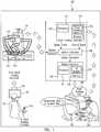
- Fig. 1is a high level diagrammatic view of a minimally invasive teleoperated surgical system 100, for example, the da Vinci® Surgical System, including a hand tracking system.
- a minimally invasive teleoperated surgical system 100for example, the da Vinci® Surgical System, including a hand tracking system.
- Further information regarding minimally invasive surgical systemsmay be found for example in U.S. Patent Application No. 11/762,165 (filed June 13, 2007 , disclosing "Minimally Invasive Surgical System"), and U.S. Patent No. 6,331,181 (issued on December 18, 2001 , disclosing "Surgical Robotic Tools, Data Architecture, And Use”). See also e.g., U.S. Patents No.
- system 100includes a cart 110 with a plurality of manipulators.
- Each manipulator and the teleoperated slave surgical instrument controlled by that manipulatorcan be coupled to and decoupled from master tool manipulators on surgeon's console 185, and in addition they can be coupled to and decoupled from mechanically ungrounded unpowered master finger tracking grip 170, sometimes called master finger tracking grip 170.
- a stereoscopic endoscope 112 mounted on manipulator 113provides an image of surgical site 103 within patient 111 that is displayed on display 187 and on the display in surgeon's console 185.
- the imageincludes images of any of the slave surgical devices in the field of view of stereoscopic endoscope 112.
- the interactions between the master tool manipulators on surgeon's console 185, the slave surgical devices and stereoscopic endoscope 112are the same as in a known system and so are known to those knowledgeable in the field.
- surgeon 181moves at least one digit of the surgeon's hand, which in turn causes a sensor in master finger tracking grip 170 to change location.
- Hand tracking transmitter 175provides a field so that the new position and orientation of the digit is sensed by master finger tracking grip 170. The new sensed position and orientation are provided to hand tracking controller 130.
- hand tracking controller 130maps the sensed position and orientation to a control point position and a control point orientation in an eye coordinate system of surgeon 181.
- Hand tracking controller 130sends this location information to system controller 140 that in turn sends a system command to the teleoperated slave surgical instrument coupled to master finger tracking grip 170.
- system controller 140that in turn sends a system command to the teleoperated slave surgical instrument coupled to master finger tracking grip 170.
- surgeon 181can control, for example, the grip of an end effector of the teleoperated slave surgical instrument, as well as the roll and yaw of a wrist coupled to the end effector.
- hand tracking of at least a part of the hand of surgeon 181 or of the hand of surgeon 180is used by hand tracking controller 130 to determine whether a hand gesture pose is made by the surgeon, or a combination of a hand gesture pose and a hand gesture trajectory is made by the surgeon.
- Each hand gesture pose and each trajectory combined with a hand gesture poseis mapped to a different system command.
- the system commandscontrol, for example, system mode changes and control other aspects of minimally invasive surgical system 100.
- a hand gestureis used (i) to initiate following between motions of the master tool grip and the associated teleoperated slave surgical instrument, (ii) for master clutch activation (which decouples master control of the slave instrument), (iii) for endoscopic camera control (which allows the master to control endoscope movement or features, such as focus or electronic zoom), (iv)for robotic arm swap (which swaps a particular master control between two slave instruments), and (v) for TILEPROTM swap, (which toggles the display of auxiliary video windows on the surgeon's display).
- TILEPROis a trademark of Intuitive Surgical, Inc. of Sunnyvale, CA, USA.
- surgeon 180When there are only two master tool grips in system 100 and surgeon 180 wants to control movement of a slave surgical instrument other than the two teleoperated slave surgical instruments coupled to the two master tool grips, the surgeon may lock one or both of the two teleoperated slave surgical instruments in place using a first hand gesture. The surgeon then associates one or both of the master tool grips with other slave surgical instruments held by other of the manipulator arms by using a different hand gesture that in this implementation provides swap association of the master tool grip to another teleoperated slave surgical instrument. Surgeon 181 performs an equivalent procedure when there are only two master finger tracking grips in system 100.
- a hand tracking unit 186 mounted in surgeon's console 185tracks at least a part of the hand of surgeon 180 and sends the sensed location information to hand tracking controller 130.
- Hand tracking controller 130determines when the surgeon's hand is close enough to the master tool grip to permit system following, e.g., the motion of the slave surgical instrument follows the motion of the master tool grip.
- hand tracking controller 130determines the position of the surgeon's hand and the position of the corresponding master tool grip. If the difference in the two positions is within a predetermined distance, e.g., less than a threshold separation, following is permitted, and otherwise following is inhibited.
- distanceis used as a measure of presence of the surgeon's hand with respect to the master tool grip on surgeon's console 185.
- display of a user interface on a displayis inhibited, e.g., turned off on a display device.
- the user interfaceis displayed on the display device, e.g., turned on.
- Presence detection of the surgeon's handhas been a long standing problem. Presence detection has been attempted many times using different contact sensing technologies, such as capacitive switches, pressure sensors, and mechanical switches. However, these approaches are inherently problematic because surgeons have different preferences in how and where they hold the master tool grip. Using distance as a measure of presence is advantageous because this type of presence detection allows the surgeon to touch the master tool grip lightly and then momentarily break physical contact to adjust the master tool grip, but it does not constrain how the surgeon holds the master tool grip with his/her fingers.
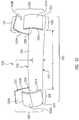
- Master finger tracking grip 270includes digit mounted sensors 211, 212, sometimes referred to as finger and thumb mounted sensors 211, 212, which independently track the location (position and orientation in one example) of each of a tip of index finger 292B and a tip of thumb 292A, i.e., track the location of two digits of the surgeon's hand.
- digit mounted sensors 211, 212sometimes referred to as finger and thumb mounted sensors 211, 212, which independently track the location (position and orientation in one example) of each of a tip of index finger 292B and a tip of thumb 292A, i.e., track the location of two digits of the surgeon's hand.
- the location of the hand itselfis tracked as opposed to tracking the location of master tool grips in a known minimally invasive surgical system.
- the sensorsprovide tracking of six degrees of freedom (three translation and three rotation) for each digit of the hand upon which a sensor is mounted. In another aspect, the sensors provide tracking of five degrees of freedom (three translation and two rotation) for each digit of the hand upon which a sensor is mounted.
- the sensorsprovide tracking of three degrees of freedom (three translation) for each digit of the hand upon which a sensor is mounted.
- the total six translational degrees of freedomare sufficient to control a slave surgical instrument that does not include a wrist mechanism.
- a padded foam connector 210is connected between finger and thumb mounted sensors 211, 212.
- Connector 210constrains thumb 292A and index finger 292B, i.e., the digits of hand 291R, to be within a fixed distance, i.e., there is a maximum separation distance between the digits of hand 291R upon which master finger tracking grip 270 is mounted.
- thumb 292A and forefinger 292Bare moved from the maximum separation ( Fig. 2A ) to a completely closed configuration ( Fig. 2D )
- the paddingprovides positive feedback to help surgeon 181 control the grip force of an end effector of a teleoperated slave surgical instrument coupled to master finger tracking grip 170.
- Figs. 2A and 2Drepresent positions that are mapped to intermediate grip forces.
- the locations (positions and orientations) of thumb 292A and forefinger 292B in Figs. 2A to 2Dare mapped to a grip closure parameter, e.g., a normalized grip closure value that is used to control the grip of the teleoperated slave surgical instrument coupled to master finger tracking grip 270.
- a grip closure parametere.g., a normalized grip closure value that is used to control the grip of the teleoperated slave surgical instrument coupled to master finger tracking grip 270.
- the sensed locations of thumb 292A and forefinger 292Bare mapped to the grip closure parameter by hand tracking controller 130.
- a location of a part of the hand of surgeon 181is tracked.
- a system control parameter of minimally invasive surgical system 100i.e., a grip closure parameter
- hand tracking controller 130i.e., a grip closure parameter
- system controller 140uses the grip closure parameter in generating a system command that is sent to the teleoperated slave surgical instrument.
- the system commandinstructs the teleoperated surgical instrument to configure an end effector to have a grip closure corresponding to the grip closure parameter.
- minimally invasive surgical system 100uses the grip closure parameter to control operation of the teleoperated slave surgical instrument of minimally invasive surgical system 100.
- the locations (position and orientation) of thumb 292A and forefinger 292B in Figs. 2A to 2Dare mapped to a control point position and a control point orientation by hand tracking controller 130.
- the control point position and control point orientationare mapped into an eye coordinate system for surgeon 181, and then provided to system controller 140 via a command signal.
- the control point position and control point orientation in the eye coordinate systemare used by system controller 140 for teleoperation of the slave surgical instrument coupled to master finger tracking grip 170.
- a location of a part of the hand of surgeon 181is tracked. Based on the tracked location, another system control parameter of minimally invasive surgical system 100, i.e., the control point position and orientation, is generated by hand tracking controller 130.
- Hand tracking controller 130transmits a command signal with the control point position and orientation to system controller 140.
- System controller 140uses the control point position and orientation in generating a system command that is sent to the teleoperated slave surgical instrument.
- the system commandinstructs the teleoperated surgical instrument to position the teleoperated surgical instrument based on the control point position and orientation.
- minimally invasive surgical system 100uses the control point position and orientation to control operation of the teleoperated slave surgical instrument of minimally invasive surgical system 100.
- the position of the control pointremains relatively stationary since the finger and thumb are each sliding in a symmetric manner along axis 295. While the motions of the finger and thumb are not completely symmetrical motions, the position still remains sufficiently stationary that the user can easily correct any perturbation that may occur.
- Hand tracking controller 130converts the relative motion into an orientation for the teleoperated slave surgical instrument coupled to master finger tracking grip 170. Hand tracking controller 130 sends a command signal with the orientation to system controller 140. While this orientation is an absolute orientation mapping, system controller 140, in one aspect, uses this input with ratcheting during teleoperation in the same matter as an orientation input from any other passive gimbal master tool grip.
- ratchetingis described in commonly assigned U.S. Patent Application No. 12/495,213 (filed on June 30, 2009 , disclosing "Ratcheting For Master Alignment Of A Teleoperated Surgical Instrument").
- System controller 140uses the orientation in generating a system command that is sent to the teleoperated slave surgical instrument.
- the system commandinstructs the teleoperated surgical instrument to rotate the teleoperated surgical instrument based on the orientation.
- minimally invasive surgical system 100uses the motion between the two digits to control of operation of the teleoperated slave surgical instrument of minimally invasive surgical system 100.
- the orientationis a roll
- the system commandresults in a tip roll of the slave surgical instrument wrist along its pointing direction.
- the motionis a second motion different from the first motion, e.g., sliding the index finger and thumb up and back lengthwise along each other ( Fig. 2F )
- the orientationis a yaw
- the system commandresults in a yaw motion of the slave surgical instrument wrist.
- both handsare tracked and control points and orientations for both hands are generated based on the sensed positions and orientations of the sensors mounted on the hands in one aspect. For example, as illustrated in Fig. 2G , the tips of the thumb and the forefinger of each hand are touched together to form a circular-like shape. The sensed position of each hand is mapped by hand tracking controller 130 to a pair of control point positions. The pair of control points is sent with a camera control system event to system controller 140.
- a location of a part of each hand of surgeon 181is tracked.
- Another system control parameter of minimally invasive surgical system 100i.e., the pair of control point positions, based on the tracked location is generated by hand tracking controller 130.
- Hand tracking controller 130sends the pair of control point positions with a camera control system event to system controller 140.
- system controller 140In response to the camera control system event, system controller 140 generates a camera control system command based on the pair of control point positions.
- the camera control system commandis sent to a teleoperated endoscopic camera manipulator in minimally invasive surgical system 100.
- minimally invasive surgical system 100uses the pair of control point positions to control operation of the teleoperated endoscopic camera manipulator of minimally invasive surgical system 100.
- hand tracking controller 130detects a hand gesture pose, or a hand gesture pose and a hand gesture trajectory. Controller 130 maps hand gesture poses to certain system mode control commands, and similarly controller 130 maps hand gesture trajectories to other system mode control commands. Note that the mapping of poses and trajectories is independent and so this is different from, for example, manual signal language tracking.
- the ability to generate system commands and to control system 100 using hand gesture poses and hand gesture trajectories, in place of manipulating switches, numerous foot pedals, etc. as in known minimally invasive surgical systems,provides greater ease of use of system 100 for the surgeon.
- control system 100When a surgeon is standing, the use of hand gesture poses and hand gesture trajectories to control system 100 makes it is unnecessary for the surgeon to take the surgeon's eyes off the patient and/or viewing screen and to search for a foot petal or a switch when the surgeon wants to change the system mode. Finally, the elimination of the various switches and foot pedals reduces the floor space required by the minimally invasive teleoperated surgical system.
- the particular set of hand gesture poses and hand gesture trajectories used to control minimally invasive surgical system 100are not critical so long as each hand gesture pose and each hand gesture trajectory is unambiguous.
- one hand gesture poseshould not be able to be interpreted by hand tracking controller 130 as one or more other hand gesture poses in the set of poses, and one hand gesture trajectory should not be interpreted as more than one hand gesture trajectory in the set of trajectories.
- the hand gesture poses and hand gesture trajectories discussed beloware illustrative only and are not intended to be limiting.
- Figs. 3A to 3Dare examples of hand gesture poses 300A to 300D, respectively.
- Figs. 4A to 4Care examples of hand gesture trajectories. Note, for example, that the configuration in Fig. 2A appears similar to that in Fig. 3A , but the operating mode of minimally invasive surgical system 100 is different when the two configurations are used.
- the teleoperated minimally invasive slave surgical instrumentis coupled to master finger tracking grip 170 and system 100 is in the following mode so that movement of the teleoperated minimally invasive slave surgical instrument follows the tracked movement of the surgeon's hand.
- the surgeonplaces system 100 in gesture recognition mode, and then makes one of the illustrated hand gesture poses or hand gesture trajectories.
- the hand gesture poses and hand gesture trajectoriesare used in control of the system modes and are not used in the following mode of operation.
- the system modes controlled with hand gesture posesare to enable, disable, and cycle between visuals displays, to clutch the visual display, and to draw/erase telestration.
- hand gesture pose 300A( Fig. 3A ) thumb 292A and index finger 292 are separated beyond a master clutch threshold, e.g., the spread between the two digits of hand 291R is greater than 115 mm.
- Hand gesture pose 300B( Fig. 3B ) with index finger 292B extended and thumb 292A curled is used to signal hand tracking controller 130 that the surgeon is tracing a hand gesture trajectory (See Figs. 4A and 4B ).
- Hand gesture pose 300C( Fig. 3C ) with thumb 292A up and index finger 292B curled is used to turn on a user interface and to cycle between modes in the user interface.
- Hand gesture pose 300D( Fig. 3D ) with thumb 292A down and index finger 292B curled is used to turn-off the user interface.
- Other hand gesture posescould include an "A-okay" hand gesture pose, an L-shaped hand gesture pose, etc.
- Hand tracking controller 130uses a multi-dimensional feature vector to recognize and identify a hand gesture pose. Initially, a plurality of hand gesture poses is specified. Next, a feature set that includes a plurality of features is specified. The feature set is designed to uniquely identify each hand gesture pose in the plurality of poses.
- a hand gesture pose recognition processis trained using a training database.
- the training databaseincludes a plurality of instances of each of the hand gesture poses.
- the plurality of instancesincludes feature vectors for the poses made by a number of different persons.
- a feature setis generated for each of the instances in the training database. These feature sets are used for training a multidimensional Bayesian classifier, as explained more completely below.
- Hand tracking unit 186sends signals representing the sensed positions and orientations of the thumb and index finger of the surgeon's hand or hands to hand tracking controller 130.
- hand tracking controller 130uses the trained multidimensional Bayesian classifier and a Mahalanobis distance to determine the likelihood, i.e., probability, that the observed feature set is a feature set of a hand gesture pose in the plurality of poses. This is done for each of the hand gesture poses in the plurality of poses.
- the hand gesture pose in the plurality of poses that is selected by hand tracking controller 130 as the observed hand gesture poseis the one having the smallest Mahalanobis distance if the Mahalanobis distance is less than the maximum Mahalanobis distance in the training database for that hand gesture pose.
- the selected hand gesture poseis mapped to a system event.
- Hand tracking controller 130injects the system event to system controller 140.
- System controller 140processes the system event and issues a system command. For example, if hand gesture pose 300C ( Fig. 3C ) is detected, system controller 140 sends a system command to display controller 150 to turn on the user interface. In response, display controller 150 executes at least a part of user interface module 155 on processor 151 to generate a user interface on the display of surgeon's console 185.
- minimally invasive surgical system 100tracks a location of part of a human hand. Based on the tracked location, a system control parameter is generated, e.g., a hand gesture pose is selected. The hand gesture pose is used to control the user interface of minimally invasive surgical system 100, e.g., display the user interface on the display of surgeon's console 185.
- a system control parameteris generated, e.g., a hand gesture pose is selected.
- the hand gesture poseis used to control the user interface of minimally invasive surgical system 100, e.g., display the user interface on the display of surgeon's console 185.
- User interface controlis illustrative only and is not intended to be limiting.
- a hand gesturecan be used to perform any of the mode changes in a known minimally invasive surgical system, e.g., master clutch, camera control, camera focus, manipulator arm swapping, etc.
- the hand gesture pose recognition processdetermines that the observed hand gesture pose is the hand gesture pose for a hand gesture trajectory, a system event is not injected by hand tracking controller 130 based on the recognition of the pose. Instead, a hand gesture trajectory recognition process is initiated.
- hand gesture pose 300B( Fig. 3B ) is the pose used to generate a hand gesture trajectory.
- Figs. 4A and 4Bare two-dimensional examples of hand gesture trajectories 400A and 400B that are made using hand gesture pose 300B.
- Fig. 4Cpresents other two-dimensional examples of hand gesture trajectories that may be used.
- the hand gesture trajectory recognition processuses a Hidden Markov Model ⁇ .
- a training databaseis needed.
- a set of hand gesture trajectoriesare specified.
- the sixteen hand gesture trajectories of Fig. 4Care selected.
- a number of test subjectsare selected to make each of the hand gesture trajectories.
- each test subjectperformed each trajectory a predetermined number of times.
- the position and orientation data for each of the subjects for each trajectory performedwas saved in the training database.
- the training databasewas used to train a discrete left-right Hidden Markov Model using an iterative Baum-Welch method.
- hand tracking controller 130determines which hand gesture trajectory corresponds to the observed symbol sequence.
- hand tracking controller 130uses the forward recursion algorithm with the Hidden Markov Model ⁇ to generate the total probability of the observed symbol sequence. The hand gesture trajectory with the highest probability is selected if that probability is greater than a threshold probability. If the highest probability is less than the threshold probability, no hand gesture trajectory is selected, and the processing ends.
- the selected hand gesture trajectoryis mapped to a system event.
- Hand tracking controller 130injects the system event to system controller 140.
- System controller 140processes the system event and issues a system command. For example, if the selected hand gesture trajectory mapped to an event to change the illumination level on the surgical site, system controller 140 sends a system event to a controller in an illuminator to change the illumination level.
- hand tracking controller 130tracks at least a part of a hand of surgeon 180B ( Fig. 6A ).
- Hand tracking controller 130generates a location of a master tool grip, e.g., master tool grip 621 ( Fig. 6B ), which represents master tool grips 621L, 621R ( Fig. 6A ), and a location of the part of the hand.
- Hand tracking controller 130maps the two locations into a common coordinate frame and then determines the distance between the two locations in the common coordinate frame. The distance is a system control parameter of a minimally invasive surgical system that is based on the tracked location of the part of the surgeon's hand.
- a safe thresholdi.e., less than a maximum permitted separation between the part of the hand and the master tool grip
- teleoperation of minimally invasive surgical system 100is permitted, and otherwise, teleoperation is inhibited.
- a safe thresholdi.e., less than a maximum permitted separation between the part of the hand and the master tool grip
- display of a user interface on a display of minimally invasive surgical system 100is inhibited, and otherwise the display of the user interface is permitted
- the distanceis used in controlling teleoperation of minimally invasive surgical system 100.
- hand tracking controller 130sends a system event to system controller 140 indicating whether teleoperation is permitted.
- system controller 140configures system 100 to either allow or inhibit teleoperation.
- pulsed DC electromagnetic trackingis used with sensors mounted on two digits of a hand, e.g., the thumb and forefinger, as illustrated in Figs. 2A to 2D and Fig. 7 .
- Each sensormeasures six degrees of freedom and in one aspect has a size of eight millimeters by two millimeters by one and one half millimeters (8 mm x 2 mm x 1.5 mm).
- the tracking systemhas a 0.8 m hemisphere dexterous workspace and a position sensing resolution of 0.5 mm and 0.1 degrees.
- the update rateis 160 Hertz and has a sensing latency of four milliseconds. When integrated into a system, additional latency may be incurred due to communication and additional filtering. Effective command latency up to 30 milliseconds has been found to be acceptable
- a tracking systemincludes an electromagnetic hand tracking controller, sensors for use in the master finger tracking grip, and a hand-tracking transmitter.
- a tracking system suitable for use in one embodiment of this inventionis available from Ascension Technology Corporation of Burlington, Vermont, USA as a 3D guidance trakSTARTM System with a Mid-Range Transmitter. (trakSTARTM is a trademark of Ascension Technology Corporation.)
- the transmittergenerates pulsed DC magnetic fields for high accuracy tracking over medium ranges, which is specified as 78 centimeters (31 inches).
- This systemprovides dynamic tracking with 240 to 420 updates/second for each sensor.
- the outputs of the miniaturized passive sensorsare unaffected by power line noise sources. A clear line-of-sight between the transmitter and the sensors is not required. There is all attitude tracking and no inertial drift or optical interference. There is high metal immunity and no distortion from nonmagnetic metals.
- a pen-like devicecould be held by the surgeon.
- the pen-like deviceis a finger piece with three or more non-colinear fiducial markers on the external surface of the device.
- more fiducial markersare used due to self occlusion.
- the fiducial markersare sufficient to determine six degrees of freedom (three translation and three rotation) motion of the finger piece and thus that of the hand holding the pen-like device.
- the pen-like devicealso senses gripping in one aspect.
- the pen-like deviceis viewed by two or more cameras of known parameters to localize the fiducial markers in three dimensions and to infer the three-dimensional pose of the finger piece.
- the fiducial markerscan be implemented, for example, as 1) retro-reflective spheres with illumination close to the camera; 2) concave or convex half spheres with illumination close to the camera; or 3) active markers such as a (blinking) LED.
- near infrared illumination of the finger pieceis used, and filters are used to block the visible spectrum at the camera to minimize the distraction from background clutter.
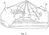
- a data glove 501( Fig. 5 ) or bare hand 502 is used, and fiducial markers 511 are attached to the thumb and index finger of glove 501 (and/or to other digits of the glove) that the surgeon is going to wear and/or directly to the skin of hand 502.
- fiducial markers 511are attached to the thumb and index finger of glove 501 (and/or to other digits of the glove) that the surgeon is going to wear and/or directly to the skin of hand 502.
- redundant markerscan be used to accommodate self-occlusion.
- Fiducial markersalso can be placed on other fingers to enable more user interface features through specifically defined hand gestures.
- the three-dimensional locations of the fiducial markersare computed by triangulation of multiple cameras having a common field of view.
- the three-dimensional locations of the fiducial markersare used to infer the three-dimensional pose (translation and orientation) of the hand and also the grip size.
- the marker locationsneed to be calibrated before use. For example, the surgeon can show the hand with markers in different poses to the camera. The different poses are then used in the calibration.
- marker-less hand trackingis used.
- Articulated hand motioncan be tracked by using images viewed from one or more cameras and processing these images via executing computer software.
- the executing computer softwaredoes not need to track all the degrees of freedom of the hand to be useful.
- the executing softwareonly needs to track the part related to the two digits of a hand to be useful for controlling a surgical tool as demonstrated herein.
- the accuracy of the measurementsdepends on the localization accuracy of the markers in the image; three-dimensional reconstruction accuracy due to camera geometry; and redundant data such as more than a minimal number, e.g., three, of fiducial markers, more than a minimal number (one or two) of cameras, and temporal averaging and filtering.
- the three-dimensional reconstruction accuracyrelies heavily on the accuracy of camera calibration.
- Some fiducial markers attached to known locations on the surgeon's consolecan be used to determine the extrinsic parameters (rotation and translation) of multiple cameras with respect to the surgeon's console. This process can be done automatically.
- Active fiducial markerscan be used for the calibration fiducial markers since such markers are only turned on during a calibration process and before the procedure. During the procedure, the calibration fiducial markers are turned off to avoid confusion with the fiducial markers used to localize the surgeon's hands.
- the relative extrinsic parameterscan also be computed by observing a moving marker in the common field of view of the cameras.
- tracking technologiesthat are suitable for use include, but are not limited to, inertial tracking, depth camera tracking, and fiber bend sensing.
- a sensor elementcan be a sensor for any of the hand tracking technologies described above, e.g., a passive electromagnetic sensor, a fiducial marker, or a sensor for any of the other technologies.
- surgeon's console 185Bis an example of surgeon's console 185.
- Surgeon's console 185Bincludes a three-dimensional viewer 610, sometimes referred to as viewer 610, master tool manipulators 620L, 620R with master tool grips 621L, 621R, and a base 630.
- Master tool grip 621( Fig. 6B ) is a more detailed diagram of master tool grips 621L, 621R.
- Master tool grips 621L, 621R of master tool manipulators 620L, 620Rare held by surgeon 180B using the forefinger and thumb, so that targeting and grasping involves intuitive pointing and pinching motions.
- Master tool manipulators 620L, 620R in combination with master tool grips 621L, 621Rare used to control teleoperated slave surgical instruments, teleoperated endoscopes, etc. in the same manner as known master tool manipulators in a known minimally invasive teleoperated surgical system.
- the position coordinates of master tool manipulators 620L, 620R and master tool grips 621L, 621Rare known from the kinematics used in controlling the slave surgical instruments.
- viewer 610displays three-dimensional images of surgical site 103 from stereoscopic endoscope 112.
- Viewer 610is positioned on console 185B ( Fig. 6B ) near the surgeon's hands so that the image of the surgical site seen in viewer 610 is oriented so that surgeon 180B feels that he or she is actually looking directly down onto surgical site 103.
- the surgical instruments in the imageappear to be located substantially where the surgeon's hands are located and oriented substantially as surgeon 180B would expect based on the position of his hands. However, surgeon 180B can see neither his or her hands, nor the position or orientation of master tool grips 621L, 621R, while viewing the displayed image of the surgical site in viewer 610.
- master tool manipulators 620L, 620Rare moved from directly in front of surgeon 180B and under viewer 610 so that they are positioned over base 630, and so that they are no longer positioned under viewer 610, i.e., the master tool manipulators are parked out of the way of the hand gesture. This provides an unobstructed volume under viewer 610 in which surgeon 180B can make hand gestures, either or both of hand gesture poses or hand gesture trajectories.
- a view coordinate system 660a view coordinate system 660
- a world coordinate system 670a tracker coordinate system 650.
- Note equivalent coordinate systemsare defined for surgeon 181 ( Fig. 1 ), so that the mapping described more completely below can be done for tracking data from master finger tracking grip 170 or from master tool grips 621L, 621R. See for example, U.S. Patent Application No. 12/617,937 , entitled "Patient-Side Surgeon Interface For a Minimally Invasive Teleoperated Surgical Instrument," filed on 13 November 2009.
- surgeon 180Bis looking down Z-axis Zview.
- Y-axis Yviewpoints upward in the display.
- X-axis Xviewpoints to the left in the display.
- Z-axis Zworldis a vertical axis.
- World X-axis Xworld and world Y-axis Yworldare in a plane perpendicular to Z-axis Zworld.
- Fig. 6Bis a more detailed illustration of master tool grip 621 and master tool manipulators 620. Coordinate systems 680, 690 are discussed more completely below with respect to method 1100 of Fig. 11 .
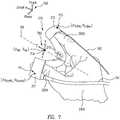
- Fig. 7is an illustration of sensor 212 mounted on forefinger 292B with a location 713 in tracking coordinate system 750, and a sensor 211 mounted on thumb 292A with a location 711 in tracking coordinate system 750.
- Sensors 211 and 212are part of the electromagnetic tracking system described above.
- Thumb 292A and index finger 292Bare examples of digits of right hand 291R.
- a part of a human handincludes at least one digit of the hand.
- the fingerssometimes called digits or phalanges, of the hand are the thumb (first digit), index finger (second digit; forefinger), middle finger (third digit), ring finger (fourth digit), and little finger (fifth digit).
- thumb and index fingerare used as examples of two digits of a human hand. This is illustrative only and is not intended to be limiting.
- the thumb and the middle fingercould be used in place of the thumb and index finger.
- the description hereinis directly applicable to the use of the middle finger also.
- the use of the right handis illustrative only.
- the description hereinis directly applicable to the left hand also.
- a cable 741, 742connects sensors 211, 212 of master finger tracking grip 270 to hand tracking controller 130.
- cable 741, 742carries position and orientation information from sensors 211, 212 to hand tracking controller 130.
- Cable 741, 742does not inhibit motion of master finger tracking grip 270. Since master finger tracking grip 270 is mechanically ungrounded, each master finger tracking grip is effectively unconstrained for both position and orientation motions within the surgeon's reachable workspace and the hand-tracking transmitter's workspace (e.g., left-right, up-down, in-out, roll, pitch, and yaw in a Cartesian coordinate system).
- each sensor 211, 212 on master finger tracking grip 270senses three degrees of translation and three degrees of rotation, i.e., six degrees of freedom. Thus, the sensed data from the two sensors represents twelve degrees of freedom. In another aspect, each sensor 211, 212 on master finger tracking grip 270 senses three degrees of translation and two degrees of rotation (yaw and pitch), i.e., five degrees of freedom. Thus, the sensed data from the two sensors represents ten degrees of freedom.
- sensors 211, 212provide redundant degrees of freedom. As described above and more completely below, the redundant degrees of freedom are mapped to parameters used to control teleoperated slave surgical instrument aspects other than position and orientation.
- each sensor 211, 212senses only three translation degrees of freedom and so together represent six degrees of freedom. This is sufficient to control three degrees of translation, roll, and grip closure of a slave surgical instrument that does not include a wrist mechanism.
- the following descriptionis used to generate the control point location using the six degrees of freedom.
- the control point orientationis taken as the orientation of the slave surgical instrument.
- the grip closure parameteris determined as described below using the control point location and the control point orientation.
- the rollis determined as described above using the relative motion of the thumb and index finger.
- index finger sensor 212In either the aspect where the sensors sense six degrees of freedom, or where the sensors sense five degrees of freedom, index finger sensor 212 generates a signal representing an index finger position p index and an index finger orientation R index in tracking coordinate frame 750. Thumb sensor 211 generates a signal representing a thumb position p thumb and a thumb orientation R thumb in tracking coordinate frame 750. In one aspect, positions p index and p thumb are taken as aligned with the center of the user's fingernail on index finger 292B and the center of the user's thumbnail on thumb 292A, respectively.
- positions p index and p thumbare each represented as a three-by-one vector in tracking coordinate frame 750. Positions p index and p thumb are in tracker coordinates.
- a control point position p cpis centered between index finger 292B and thumb 292A.
- Control point position p cpis in control point frame 790, but is specified in tracker coordinates.
- the Z-axis of control point frame 790extends through control point position p cp in the pointing direction, as described more completely below.
- index finger 292B and thumb 292Aare mapped to the jaws of a slave surgical instrument, but the two digits are more dexterous than the instrument jaws.
- the Y-axis of control point frame 790corresponds to the pin used for instrument jaw closure.
- the Y-axis of control point frame 790is perpendicular to a vector between index finger 292B and thumb 292A, as described below.
- Control point position p cpis represented as a three-by-one vector in tracker coordinates of tracking coordinate frame 750.
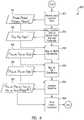
- Fig. 8is a process flow diagram for mapping a location of part of a hand to a grip closure parameter used to control the grip of a slave surgical instrument, e.g., one of the teleoperated slave surgical instruments in Fig. 1 .
- This mappingalso maps a temporal change in the location to a new grip closure parameter and a corresponding location of a slave instrument tip and the velocity in moving to that location.
- RECEIVE HAND LOCATION DATA process 810receives index finger position and orientation (p index , R index ) and thumb position and orientation (p thumb , R thumb ), which in this example are stored as data 811. Index finger position and orientation (p index , R index ) and thumb position and orientation (p thumb , R thumb ) are based on data from the tracking system. Process 810 transfers to MAP LOCATION DATA TO CONTROL POINT AND GRIP PARAMETER process 820.
- MAP LOCATION DATA TO CONTROL POINT AND GRIP PARAMETER process 820generates a control point position p cp , a control point orientation R cp , and a grip closure parameter g grip using index finger position and orientation (p index , R index ) and thumb position and orientation (p thumb , R thumb ).
- Control point position p cp , control point orientation R cp , and grip closure parameter g gripare stored as data 821.
- control point mapping performed in process 820is defined to emulate key properties of the known master tool manipulators control point placement.
- the response to thumb and index finger motionwill be familiar and intuitive to users of the known teleoperated minimally invasive surgical system with a surgeon's console similar to surgeon's console 180B ( Fig. 6A ).
- Fig. 9is a more detailed process flow diagram for one aspect of MAP LOCATION DATA TO CONTROL POINT AND GRIP PARAMETER process 820.
- Control point position p cpis the average of finger position p index and thumb position p thumb .
- MAP HAND POSITION DATA TO CONTROL POINT process 910transfers processing to GENERATE CONTROL POINT ORIENTATION process 920.
- the Z-axis of the control point orientationis aligned in the pointing direction.
- Vector ⁇is a vector perpendicular to index finger pointing direction vector ⁇ index and thumb pointing direction vector ⁇ thumb .
- Angle ⁇is the magnitude of the angle between index finger pointing direction vector ⁇ index and thumb pointing direction vector ⁇ thumb .
- process 910has generated control point position p cp and the initial part of process 920 has generated the approximate pointing direction of the Z-axis in control point frame 790.
- mappinguses the relative positions of the index finger and thumb to effectively roll and yaw the control point as if manipulating a small gimbal between the fingers.
- the remainder of process 920is performed as follows to generate a complete set of orthonormal control point unit vectors axes x ⁇ cp , ⁇ cp , and ⁇ cp .
- process 820has mapped index finger and thumb positions and orientations (p index , R index ), (p thumb , R thumb ) to control point position and orientation (p cp , R cp ).
- Process 820must still generate grip closure parameter g grip .
- GENERATE CONTROL POINT ORIENTATION process 920transfers processing to GENERATE GRIP CLOSURE PARAMETER process 930.
- grip closureis determined by the distances of index finger position p index and thumb position p thumb from the centerline axis defined by control point position p cp and Z-axis direction ⁇ cp . This allows grip closure to be invariant to sliding when the thumb and forefinger are touching.
- index finger position p index and thumb position p thumbare mapped onto the Z-axis in frame 790.
- Position p index_projis the projection of index finger position p index onto the Z-axis of frame 790
- position p thumb_projis the projection of thumb position p thumb onto the Z-axis of frame 790.
- p index _ projp cp + z ⁇ cp ⁇ p index ⁇ p cp ⁇ z ⁇ cp
- thumb _ projp cp + z ⁇ cp ⁇ p thumb ⁇ p cp ⁇ z ⁇ cp
- Evaluation grip closure distance d valis bounded by a maximum distance threshold d max and a minimum distance threshold d min .
- padded foam connector 210 between sensors 211, 212constrains the digits to be within a fixed separation, i.e., between a maximum distance threshold d max and a minimum distance threshold d min .
- a neutral distance d 0corresponds to the separation distance when the two digits are just touching.
- a maximum distance threshold d maxFor a particular set of sensors and a connector, a maximum distance threshold d max , a minimum distance threshold d min , and neutral distance d 0 are empirically determined.
- three different combinations of sensors and a connectorare provided for small, average, and large hands. Each combination has its own maximum distance threshold d max , minimum distance threshold d min , and neutral distance d 0 as the length of connector 210 is different in each of the combinations.
- Process 930compares distance d val to minimum distance threshold d min . If the comparison finds that distance d val is less than minimum distance threshold d min , grip closure distance d is set to minimum threshold distance d min . Otherwise, process 930 compares distance d val to maximum distance threshold d max . If the comparison finds that distance d val is greater than maximum distance threshold d max , grip closure distance d is set to maximum threshold distance dmax. Otherwise, grip closure distance d is set to distance d val .
- a grip closure distance d between maximum distance threshold d max and distance d 0is mapped to a value between zero and one.
- a grip closure distance d between minimum distance threshold d min and distance d 0is mapped to a value between minus one and zero.
- a value of one for grip closure parameter g gripis obtained when index finger 292B and thumb 292A are separated to the maximum extent permitted by connector 210 ( Fig. 2A ).
- a value of zero for grip closure parameter g gripis obtained when the tip of index finger 292B and the tip of thumb 292A are just touching ( Fig. 2C ). Values in a range between zero and one control the opening/closing of the jaws of the end effector of a slave surgical instrument.
- a value of minus one for grip closure parameter g gripis obtained when index finger 292B and thumb 292A are touching and connector 210 is fully compressed between index finger 292B and thumb 292A ( Fig. 2D ). Values in a range between zero and minus one control the jaw force of the closed jaws of the end effector.
- Connector 210provides a passive haptic cue for jaw closure.
- mapping grip closure distance d to a value in one of two rangesis illustrative only and is not intended to be limiting.
- the exampleis illustrative of mapping grip closure distance d to a value in a first range of grip closure parameter g grip to control the opening/closing of jaws of an end effector of a slave surgical instrument when grip closure distance d is greater than neutral distance d 0 .
- "opening/closing"means the opening and closing of the jaws.
- Grip closure distance dis mapped to a value in a second range of the grip closure parameter g grip to control jaw force of the closed jaws of the end effector when grip closure distance d is less than neutral distance d 0 .
- process 820has mapped index finger position and orientation (p index , R index ) and thumb position and orientation (p thumb , R thumb ) into a control point position and orientation (p cp , R cp ) and grip closure parameter g grip that is stored as data 821.
- Process 820transfers to MAP TO WORLD COORDINATES process 830 ( Fig. 8 ).
- MAP TO WORLD COORDINATES process 830receives data 821, and maps data 821 to a world coordinate system.
- a world coordinate systemSee world coordinate system 670 ( Fig. 6A ).
- grip closure parameter g gripis not changed by the mapping.
- the data in eye coordinatesis stored as data 841.
- Process 840transfers to GENERATE VELOCITIES process 850.
- the world coordinate mappingmay be eliminated.
- the control point datais mapped directly from the tracking coordinate system into the eye coordinate system without utilizing a world coordinate system.
- GENERATE VELOCITIES process 850For teleoperation, position, orientation, and velocity are needed. Thus, GENERATE VELOCITIES process 850 generates the needed velocities.
- the velocitiescan be generated in a number of ways. Some implementations, such as inertial and gyroscope sensors, can directly measure differential signals to produce a linear velocity and an angular velocity of the control point. If the velocities cannot be directly measured, process 850 estimates the velocities from the location measurements in the eye coordinate system in one aspect.
- the velocitiesmay be estimated using finite differences in the eye coordinate system over the sampling interval.
- control point linear velocity V cp_tc and control point angular velocity ⁇ cp_tcare sensed in tracker coordinates of tracker coordinate system 750 ( Fig. 7 ).
- directly sensed control point linear velocity V cp_tc and directly sensed control point angular velocity ⁇ cp_tcare rotated from tracker coordinate system 750 to eye coordinate system 660 using a rotation ec R tc .
- GENERATE VELOCITIES process 850transfers to SEND CONTROL COMMAND process 860.
- Process 860sends an appropriate system control command to the slave surgical instrument based upon the position, orientation, velocities, and grip closure parameter stored as data 851.
- processes 810 to 850are performed by hand tracking controller 130 ( Fig. 1 ). Controller 130 executes finger tracking module 135 on a processor 131 to perform processes 810 to 850. In this aspect, finger tracking module 135 is stored in memory 132. Process 850 sends a system event to system controller 140 that in turn performs process 860.
- hand tracking controller 130 and system controller 140may be implemented in practice by any combination of hardware, software that is executed on a processor, and firmware. Also, functions of these controllers, as described herein, may be performed by one unit, or divided up among different components, each of which may be implemented in turn by any combination of hardware, software that is executed on a processor, and firmware. When divided up among different components, the components may be centralized in one location or distributed across system 100 for distributed processing purposes.
- Fig. 10is a process flow diagram of one aspect of a process 1000 of hand gesture pose and hand gesture trajectory control of system 100.
- a hand gesture pose recognition process 1050uses a multi-dimensional Bayesian classifier and a hand gesture trajectory recognition process 1060 uses a discrete Hidden Markov Model ⁇ .
- Figs. 3A to 3Dare examples of hand gesture poses.
- To train hand gesture pose recognition process 1050a number of hand gesture poses are specified. The number of hand gesture poses utilized is limited by the ability to define unique poses that can unambiguously be identified by recognition process 1050, and by the ability of the surgeon to remember and reliably reproduce each of the different hand gesture poses.
- a feature set including a plurality of features f i , where i ranges from 1 to nis defined.
- Number nis the number of features used. The number of and type of features is selected so that each of the hand gesture poses in the set of permissible poses can be accurately identified. In one aspect, number n is six.
- Feature f 1is the dot product of pointing direction of ⁇ index index finger 292B and pointing direction ⁇ thumb of thumb 292A.
- Feature f 2is the distance between index finger 292B and thumb 292A.
- Feature f 3is the distance of thumb 292A projected on pointing direction ⁇ index of index finger 292B.
- Feature f 4is the distance of thumb 292A from the axis along pointing direction ⁇ index of index finger 292B.
- Feature f 5is the Z-component of pointing direction ⁇ thumb of thumb 292A.
- Feature f nis the dot product of thumb normal vector x ⁇ thumb of thumb 292A and pointing direction ⁇ index of index finger 292B.
- each hand gesture posePrior to using method 1000, it is necessary to develop a training database of hand gesture poses.
- a number of different usersproduce each hand gesture pose at least one, and the position and orientation data for each hand gesture pose for each user is measured using the tracking system. For example, each person in a group of people malces each of the permissible hand gesture poses. Index finger and thumb positions and orientations (p index , R index ), (p thumb , R thumb ) are saved for each of the hand gesture poses for each person in the group in the training database.
- ⁇ f i ⁇is generated for each hand gesture pose for each user.
- the set of training feature vectors for each hand gesture poseis then used to compute, a mean f i and a covariance ⁇ fi .
- the training databaseis used to obtain a feature vector mean and covariance for each trained gesture.
- a Mahalanobis distance d(f i )(See discussion below) is generated for each trainer and the maximum Mahalanobis distance d(f i ) for each hand gesture pose is saved as a threshold for that hand gesture pose.
- Hidden Markov Model ⁇A B ⁇
- Model parameter Nis the number of states in the model
- model parameter Mis the number of observation symbols per state.
- the three probability measuresare state transition probability distribution A , observation gesture probability distribution B, and initial state distribution ⁇ .
- transition probability distribution Ais an N X N matrix.
- Observation gesture probability distribution Bis an N X M matrix, and initial state distribution ⁇ is an N X 1 matrix.
- a training databaseis needed prior to obtaining the training database. Prior to obtaining the training database, a set of hand gesture trajectories are specified.
- test subjects jare selected to make each of the hand gesture trajectories. While in Fig. 4C , the sixteen hand gesture trajectories are presented in a two-dimensional projected form, the test subjects are unconstrained when performing the various hand gesture trajectories, which allows for some three-dimensional variations to arise. In one aspect, each subject performed each hand gesture trajectory k times, this produces j ⁇ k training sequences per hand gesture trajectory.
- Hidden Markov Model ⁇was chosen such that probability P(O
- the iterative methodwas stopped when the model converged within 0.1 percent for three successive iterations.
- Transition probability matrix Awas initialized with random entries, which were sorted in descending order on a row-by-row basis. To enforce the left-to-right structure, all entries in the lower-diagonal of transition probability matrix A were set to zero. Furthermore, transitions greater than two states were disallowed by setting entries to zero where (i - j) > 2 for all rows i and columns j . Transition probability matrix A was normalized at the end on a row-by-row basis.
- the initialization for the observation probability matrix Bpartitioned the observation sequence uniformly based on the desired number of states. Therefore, each state can initially observe one or more symbols with a probability based on a local frequency count.
- This matrixwas also normalized on a row-by-row basis. See for example, N. Liu, R.I.A. Davis, B.C. Lovell, P.J. Kootsookos, "Effect of Initial HMM Choices in Multiple Sequence Training for Gesture Recognition," International Conference on Information Technology, 5-7, Las Vegas, pgs 608-613 (April 2004 ), as a demonstration of initialization procedures for Hidden Markov Models known by those knowledgeable in the field. A Hidden Markov Model was developed for each of the hand gesture trajectories.
- GESTURE MODE ENABLED check process 1001determines whether the surgeon enabled the gesture recognition mode of operation of system 100. In one aspect, to enable gesture recognition mode, the surgeon depresses a foot pedal on surgeon's console 185 ( Fig. 1A ). If gesture recognition mode is enabled, check process 1001 transfers to RECEIVE HAND LOCATION DATA process 1010, and otherwise returns thru RETURN 1002.
- RECEIVE HAND LOCATION DATA process 1010receives index finger position and orientation (p index , R index ) and thumb position and orientation (p thumb , R thumb ) for the gesture being made by the surgeon. As noted above, index finger position and orientation (p index , R index ) and thumb position and orientation (p thumb , R thumb ) are based on data from the tracking system. Process 1010 transfers to GENERATE FEATURES PROCESS 1011.
- index finger position and orientation(p index , R index ) and thumb position and orientation (p thumb , R thumb ) are used to generate each of features f 1_o to f n_o in an observed feature vector f i_o .
- GENERATE FEATURES process 1011transfers to COMPARE FEATURE WITH KNOWN POSES process 1012.
- COMPARE FEATURE WITH KNOWN POSES process 1012compares observed feature vector f i_o with the trained feature set ⁇ f i ⁇ for each pose. This process determines the likelihood that the observed feature vector is included within a training dataset feature set ⁇ f i ⁇ for a particular hand gesture pose, i.e., corresponds to the training data set. This can be expressed as P f i _ o
- ⁇ )is: P f i _ o
- ⁇exp ⁇ 1 2 f i _ o ⁇ f ⁇ i T ⁇ fi ⁇ 1 f i _ o ⁇ f ⁇ i 2 ⁇ N / 2 ⁇ fi 1 / 2
- Nis the dimensionality of the feature vector, e.g., n in the above example.
- f ⁇ i_of i_o - f i .
- the Mahalanobis distanceis known to those knowledgeable in the field. See for example, Moghadam, Baback and Pentland, Alex, "Probabilistic Visual Learning for Object Representation," IEEE Transactions On Pattern Analysis and Machine Intelligence, Vol. 19, No. 7, pp. 696 to 710 (July 1997 ).
- thisis the expression that is evaluated to determine Mahalanobis distance d(f i_o ).
- process 1011generates a Mahalanobis distance d(f i_o ) .
- process 1012transfers to SELECT POSE process 1013.
- the hand gesture pose having the smallest Mahalanobis distance d(f i_o )is selected if Mahalanobis distance d(f i_o ) is less than the maximum Mahalanobis distance in the training database for that hand gesture pose. If Mahalanobis distance d(f i_o ) is greater than the maximum Mahalanobis distance in the training database for that hand gesture pose, no hand gesture pose is selected.
- SELECT POSE process 1012transfers to TEMORAL FILTER PROCESS 1014.
- TEMORAL FILTER process 1014determines whether the result of process 1013 has provided the same result consecutively a predetermined number of times. If process 1013 has provided the same result for the predetermined number of times, TEMPORAL FILTER process 1014 transfers to GESTURE POSE check process 1015, and otherwise returns. The predetermined number of times is selected so that TEMPORAL FILTER process 1014 prevents oscillations or transient detections when switching between hand gesture poses.
- GESTURE POSE check process 1015determines whether the selected hand gesture pose is the hand gesture pose used in a hand gesture trajectory. If the selected hand gesture pose is the hand gesture pose used in a hand gesture trajectory, GESTURE POSE check process 1015 transfers processing to GENERATE VELOCITY SEQUENCE process 1020, and otherwise transfers processing to POSE CHANGE check process 1016.
- POSE CHANGE check process 1016determines whether the hand gesture pose has changed from the last pass through method 1000. If the selected hand gesture pose is the same as the immediately previous temporal filtered gesture pose result, POSE CHANGE check process 1016 returns through RETURN 1003, and otherwise transfers to MAP TO SYSTEM EVENT process 1030.
- MAP TO SYSTEM EVENT process 1030maps the selected hand gesture pose to a system event, e.g., the system event assigned to the hand gesture pose is looked up. Upon finding the system event, MAP TO SYSTEM EVENT process 1030 transfers processing to INJECT SYSTEM EVENT process 1031.
- INJECT SYSTEM EVENT process 1031sends the system event to an event handler in system controller 140 ( Fig. 1 ).
- system controller 140sends an appropriate system command to controllers and/or other apparatus in system 100. For example, if the hand gesture pose is assigned to a turn-on user interface event, system controller 140 sends a command to display controller 150 to turn on the user interface. Display controller 150 executes the part of user interface module 155 on processor 151 needed to turn on the user interface.
- processing in method 1000transfers from GESTURE POSE check process 1015 to GENERATE VELOCITY SEQUENCE process 1020.
- the principal feature used for hand gesture trajectory recognitionis a unit velocity vector.
- the unit velocity vectoris invariant to the starting position of the gesture.
- a normalized velocity vectoraccounts for variations in size or speed of the gesture.
- the control point samplesare converted into a normalized control point velocity sequence, i.e., into a sequence of unit velocity vectors.
- process 1020transfers processing to CONVERT VELOCITY SEQUENCE INTO SYMBOL SEQUENCE process 1021.
- discrete Hidden Markov Model ⁇requires a sequence of discrete symbols as input.
- process 1021the discrete symbols are generated from the normalized control point velocity sequence through vector quantization.
- the vector quantizationwas performed using a modified K-means clustering with the condition that the process stops when the clustering assignments stop changing. While K-means clustering is used, the process leverages the fact that the features are unit vectors. In this case, vectors, which are similar in direction, are clustered. This is done using the dot-product between each unit feature vector and the normalized cluster center vectors as the similarity metric.
- the clusteringis initialized with random assignments of vectors to thirty-two clusters and the overall process is iterated multiple times, where the best clustering result is selected based on a maximum total "within” cluster cost metric. Note that in this case, the "within" cluster cost is based on a measure of similarity.
- Each of the resultant clustersis assigned a unique index, which serves as the symbol for the Hidden Markov Model.
- An input vectoris then mapped to its closest cluster mean and the corresponding index of that cluster is used as the symbol. In this way, a sequence of unit velocity vectors can be translated into a sequence of indices or symbols.
- the clustered vectorswere assigned a symbol based on a fixed eight-direction two-dimensional vector quantization codebook.
- process 1020generates an observed symbol sequence and transfers to GENERATE GESTURE PROBABILITY process 1023.
- GENERATE GESTURE PROBABILITY process 1023uses the forward recursion algorithm with the Hidden Markov Models to find a probability that each gesture matches the observed symbol sequence.
- the forward recursion algorithmis described in Rainer, " A tutorial on Hidden Markov Models and Selected Applications in Speech Recognition ,”.
- processingtransfers to SELECT TRAJECTORY process 1024.
- the hand gesture trajectory with the highest probabilityfrom among the permissible Hidden Markov Model trajectory gesture models. This probability must also be greater than a given threshold to be accepted. If the highest probability is not greater than the threshold, no hand gesture trajectory is selected. This threshold should be tuned to maximize recognition accuracy while avoiding false recognitions.
- SELECT TRAJECTORY process 1024transfers processing to TRAJECTORY FOUND check process 1025. If SELECT TRAJECTORY process 1024 selected a hand gesture trajectory, TRAJECTORY FOUND check process 1025 transfers processing to MAP TO SYSTEM EVENT process 1030, and otherwise returns through RETURN 1004.
- MAP TO SYSTEM EVENT process 1030maps the selected hand gesture trajectory to a system event, e.g., the system event assigned to the hand gesture trajectory is looked up. Upon finding the system event, MAP TO SYSTEM EVENT process 1030 transfers processing to INJECT SYSTEM EVENT process 1031.
- INJECT SYSTEM EVENT process 1031sends the system event to event handler in system controller 140 ( Fig. 1 ).
- system controller 140sends an appropriate system command to the appropriate controller(s) or apparatus. For example, if the system event is assigned to an action in the user interface, system controller 140 sends a command to display controller 150 to take that action in the user interface, e.g., change the viewing mode of the surgical site.
- Fig. 11is a process flow diagram of one aspect of a process 1100 of presence detection performed, in one aspect, by hand tracking controller 130 in system 100. Process 1100 is performed separately for each of the surgeon's hands in one aspect.
- GET JOINT ANGLES process 1110the joint angles of master tool manipulator 620 ( Fig. 6B ) are measured.
- GET JOINT ANGLES process 1110transfer processing to GENERATE FORWARD KINEMATICS process 1111.
- GENERATE FORWARD KINEMATICS process 1111Since the lengths of the various links in master tool manipulator 620 are known and the position of base 629 of master tool manipulator 620 is known, geometric relationships are used to generate the location of master tool grip 621 in master workspace coordinate system 680. Thus, GENERATE FORWARD KINEMATICS process 1111 generates position p mtm of master tool grip 621 in master workspace coordinate system 680 using the angles from process 1110. GENERATE FORWARD KINEMATICS process 1111 transfers processing to MAP TO WORLD COORDINATES process 1112.
- MAP TO WORLD COORDINATES process 1112transfers processing to GENERATE HAND TO END EFECTOR SEPARATION PROCESS 1130.
- RECEIVE HAND LOCATION DATA process 1120receives (retrieves) index finger position and orientation (p index , R index ) and thumb position and orientation (p thumb , R thumb ). Index finger position and orientation (p index , R index ) and thumb position and orientation (p thumb , R thumb ) are based on data from the tracking system. RECEIVE HAND LOCATION DATA process 1120 transfers processing to GENERATE HAND POSITION process 1121.
- GENERATE HAND POSITION process 1121maps index finger position and orientation (p index , R index ) and thumb position and orientation (p thumb , R thumb ) to a control point position and orientation in the tracking coordinate system as described above. Position P hand is the position of the control point in tracking coordinates.
- GENERATE HAND POSITION process 1121transfers processing to MAP TO WORLD COORDINATES process 1122.
- control point positionin the presence detection is illustrative only and is not intended to be limiting.
- the presence detectioncould be done for example, using the position of the tip of the index finger and using the position of the tip of the thumb, or using only one of these positions.
- the processes described beloware equivalent for each of these various positions associated with a part of a human hand.
- MAP TO WORLD COORDINATES process 1122transfers processing to GENERATE HAND TO END EFECTOR SEPARATION PROCESS 1130.
- GENERATE HAND TO END EFECTOR SEPARATION PROCESS 1130generates a separation distance d sep between position p mtm_wc in world coordinate system 670 and position p hand_wc in world coordinate system 670.
- GENERATE HAND TO END EFECTOR SEPARATION PROCESS 1130transfers processing to DISTANCE SAFE check process 1131.
- DISTANCE SAFE check process 1131compares separation distance d sep to a safe distance threshold. This threshold should be small enough to be conservative while still allowing the surgeon to change grasp or to manipulate the most distal end of the end-effector. If separation distance d sep is less than the safe distance threshold, DISTANCE SAFE check process 1131 transfers to HAND PRESENCE ON process 1140. Conversely, if separation distance d sep is greater than the safe distance threshold DISTANCE SAFE, check process 1131 transfers to HAND PRESENCE OFF process 1150.
- HAND PRESENCE ON process 1140determines whether system 100 is in teleoperation. If system 100 is in teleoperation, no action is required and teleoperation is permitted to continue, and so process 1140 transfers to start process 1100 over. If system 100 is not in teleoperation, HAND PRESENCE ON process 1140 sends a hand present event to INJECT SYSTEM EVENT process 1160 that in turn sends the hand present event to system controller 140.
- HAND PRESENCE OFF process 1150determines whether system 100 is in teleoperation. If system 100 is not in teleoperation, no action is required and so process 1150 transfers to start process 1100 over. If system 100 is in teleoperation, HAND PRESENCE OFF process 1150 sends a hand not present event to INJECT SYSTEM EVENT process 1160 that in turn sends the hand not present event to system controller 140.
- System controller 140determines whether the hand present event or the hand not present event requires any change to the system mode of operation and issues an appropriate command. In one aspect, system controller 140 enables teleoperation in response to a hand present event, e.g., permits teleoperation, and disables teleoperation in response to a hand not present event if a teleoperated minimally invasive surgical is coupled to the master tool grip. As is known to those knowledgeable in the field, a teleoperated minimally invasive surgical instrument is couplable to and decoupable from a master tool grip.
- the hand present event and hand not present eventare used by system controller 140 in combination with other events to determine whether to permit teleoperation.
- presence detection of the surgeon's headmay be combined with presence detection of the surgeon's hand or hands in determining whether to permit teleoperation.
- the hand present event and hand not present eventare used by system controller 140 to control the display of a user interface on a display of the minimally invasive surgical system.
- system controller 140receives the hand not present event, if the user interface is not turned on, system controller 140 sends a command to display controller 150 to turn on the user interface.
- Display controller 150executes the part of user interface module 155 on processor 151 needed to turn on the user interface.
- system controller 140receives the hand present event, if the user interface is turned on, system controller 140 sends a command to display controller 150 to turn off the user interface.
- Display controller 150executes the part of user interface module 155 on processor 151 needed to turn off the user interface.
- the hand present event and hand not present eventcan be used by system controller 140 in combination with other events to determine whether to display the user interface.
- the user interface display control and the teleoperation controlare examples of system mode control using presence detection and are not intended to be limiting to these two specific modes of system control.
- the presence detectioncould be used in control of a proxy visual such as those described more completely below.
- combinations of the various modese.g., teleoperation and proxy visual display, could be controlled by system controller 140 based upon the hand present event and hand not present event.
- the hand presence detectionis useful in eliminating double purposing of master tool grips 621L, 621R, e.g., pushing a foot petal and then using master tool grips 621L, 621R to control a user interface that is displayed in surgeon's console 185B.
- the master tool gripsare double purposed, e.g., used in control both of a surgical instrument and a user interface
- the surgeontypically has to press a foot pedal to switch into the user interface mode of operation. If for some reason, the surgeon fails to depress the foot petal, but believes the system has switched to the user interface mode of operation, movement of the master tool grip can result in unwanted motion of the surgical instrument.
- Presence detection process 1100is used to prevent this problem and to eliminate the double purposing of the master tool grips.
- system controller 140sends a system command to lock master tool manipulators 6201, 620R ( Fig. 6A ) in place, and sends a system command to display controller 150 to present the user interface on the display of surgeon's console 185B.
- the motion of the surgeon's handis tracked and is used to control elements in the user interface, e.g, move a slider switch, change the display, etc.
- the control pointis mapped into the eye coordinate frame and so can be associated with the location of an element in the user interface.
- the motion of the control pointis used to manipulate that element. This is accomplished without the surgeon having to activate a foot petal and is done so that the surgeon cannot inadvertently move a surgical instrument.
- thiseliminates the problems associated using the master tool grips to control both the surgical instrument and the user interface.
- the world coordinate frameis an example of a common coordinate frame.
- the use of the world coordinate frame as the common coordinate frameis illustrative only and is not intended to be limiting.
- Fig. 12is an illustration of one example of a master finger tracking grip 1270.
- Master finger tracking grip 1270is an example of master finger tracking grip 170, 270.
- Master finger tracking grip 1270includes a compressible body 1210 and two finger loops 1220, 1230.
- Compressible body 1210has a first end 1213 and a second end 1214.
- a body section 1215extends between first end 1213 and second end 1214.
- Compressible body 1210has an outer exterior surface.
- the outer exterior surfaceincludes a first portion 1216 and a second portion 1217.
- First portion 1216e.g., an upper portion, extends between first end 1213 and second end 1214.
- Second portion 1217e.g., a bottom portion, extends between first end 1213 and second end 1214. Second portion 1217 is opposite and removed from first portion 1216.
- the outer exterior surfaceis a surface of a fabric casing.
- the fabricis suitable for use in an operating room.
- the fabric casingencloses compressible foam.
- the foamis selected to provide resistance to compression, and expansion as the compression is released.
- several strips of foamwere included within the fabric casing.
- the foamalso must be capable of being bent so that first portion 1216 is positioned between first and second digits of a human hand as the tip of the first digit is moved towards the tip of the second digit.
- Body section 1215has a length L between finger loop 1220 and finger loop 1230. As explained above, length L is selected to limit the separation between a first digit in loop 1220 and a second digit in loop 1230. (See Fig. 2A .)
- body section 1215has a thickness T. As illustrated in Fig. 2C , thickness T is selected so that when master finger tracking grip 1270 is configured such that region 1236 on second portion 1217 of the outer exterior surface adjacent to end 1214 and region 1226 on second portion 1217 adjacent to end 1213 are just touching, second portion 1217 along length L is not in complete contact with itself.
- First finger loop 1220is affixed to compressible body 1210 adjacent to first end 1213. Loop 1220 extends about a region 1225 of first portion 1216 of the outer exterior surface of compressible body 1210. Upon placement of first finger loop 1220 on the first digit of the human hand, region 1225 contacts the first digit e.g., a first part of first portion 1216 of the outer exterior surface contacts the thumb.
- finger loop 1220has two ends, a first fabric end 1221A and a second fabric end 1221B.
- End 1221A and end 1221Bare ends of a fabric strip that is affixed in body 1210.
- a piece of loop fabric 1222Bis attached to an inner surface of end 1221B
- a piece of hook fabric 1222Ais attached to an outer surface of end 1221A.
- An example of hook fabric and loop fabricis a nylon fastening tape consisting of two strips of nylon fabric, one having tiny hooked threads and the other a coarse surface. The two strips form a strong bond when pressed together.
- VELCRO® fastening tapeis a registered trademark of Velcro Industries B. V.
- Second finger loop 1230is affixed to compressible body 1210 adjacent to second end 1214. Loop 1230 extends about a region 1235 of first portion 1216 of the outer exterior surface of compressible body 1210. Upon placement of second finger loop 1230 on the second digit of the human hand, region 1235 contacts the second digit, e.g., a second part of first portion 1216 of the outer exterior surface contacts the index finger. Second part 1235 of first portion is opposite and removed from fist part 1225 of the first portion.
- finger loop 1230also has two ends, a first fabric end 1231A and a second fabric end 1231B.
- End 1231A and end 1231Bare ends of a fabric strip that is affixed to body 1210.
- a piece of loop fabric 1232Bis attached to an inner surface of end 1231B, and a piece of hook fabric 1232A is attached to an outer surface of end 1231A.
- a first location tracking sensor 1211is affixed to first finger loop 1220.
- a second location tracking sensor 1212is affixed to second finger loop 1230.
- the location tracking sensorscan be any of the sensor elements described above.
- location tracking sensors 1211, 1212are passive electromagnetic sensors.
- the hand tracking control systemis used to control any one of a plurality of proxy visuals that can be used by a surgeon to proctor another surgeon. For example, when surgeon 180 ( Fig. 1A ) is being proctored by surgeon 181 using master finger tracking grip 170, surgeon 181 uses master finger tracking grip 170 to control a proxy visual of a surgical instrument, while surgeon 180 uses the master tool grip to control a teleoperated slave surgical instrument.
- surgeon 181can telestrate, or can control a virtual hand in the display. Also, surgeon 181 can demonstrate how to manipulate the master tool grip on the surgeon's console by manipulating a virtual image of master tool grip 621 that is presented in the display.
- proxy visualsare illustrative only and are not intended to be limiting.
- master finger tracking grip 170while not at a surgeon's console is also illustrative and is not intended to be limiting.
- a surgeon at a surgeon's consolecould move a hand from a master tool grip, and then use that hand to proctor another surgeon as the hand is tracked by the hand tracking system.
- a proxy visual module(not shown) is processed as part of a vision processing subsystem in one aspect.
- the executing modulereceives the position and orientation of the control point of the proctor's hand, and renders stereo images, which are composited with the endoscopic camera images in real time and displayed on any combination of surgeon console 185, the assistant display, and patient-side surgeon interface display 187.
- a proxy visual system loopis activated, e.g., the proxy visual module is executed on a processor module.
- the particular action, e.g., hand gesture pose, used as the predefined actionis not essential so long as system controller 140 ( Fig. 1 ) is configured to recognize that action.
- the proxy visualis a virtual ghost instrument 1311 ( Fig. 13 ) controlled by master finger tracking grip 170, while teleoperated slave surgical instrument 1310 is controlled by one of the master tool manipulators of surgeon's console 185.
- Surgeon 181sees both instruments 1310 and 1311 in display device 187, while surgeon 180 sees both instrument 1310 and 1311 in the stereoscopic display in surgeon's console 185.
- the use of virtual ghost instrument 1311 as a proxy visualis illustrative only and is not intended to be limiting to this particular image. In view of this disclosure, other images can be used for the proxy visual, which facilitate differentiation between the image representing the proxy visual and the image of the actual end effector of the teleoperated slave surgical instrument.
- Virtual ghost instrument 1311appears similar to actual instrument 1310, except virtual ghost instrument 1311 is displayed in a way that clearly distinguishes virtual ghost instrument 1311 from actual instrument 1310 (e.g., a transparent or translucent ghost-like image, a distinctly colored image, etc.).
- the control and operation of virtual ghost instrument 1311is the same as that described above for an actual teleoperated surgical instrument.
- surgeon 181can manipulate virtual ghost instrument 1311 using master finger tracking grip 170 to demonstrate the proper use of teleoperated slave surgical instrument 1310.
- Surgeon 180can mimic the motion of virtual ghost instrument 1311 with instrument 1310.
- the proxy visualis a pair of virtual hands 1410, 1411 ( Fig. 14 ) controlled by master finger tracking grip 170 and a second master finger tracking grip, which is not visible in Fig. 1 .
- Teleoperated slave surgical instruments 1420, 1421are controlled by the master tool manipulators of surgeon's console 185.
- Surgeon 181sees video image 1400 in display device 187, and surgeon 180 also sees video image 1400 in the stereoscopic display in surgeon's console 185.
- Virtual hands 1410, 1411are displayed in a way that clearly distinguishes them from the other objects in video image 1400.
- the opening and closing of the thumb and the forefinger of a virtual handis controlled using grip closure parameter g grip , which was described above.
- the position and orientation of the virtual handis controlled by the control point position and orientation, as described above, which are mapped into the eye coordinate space, also as described above also.
- virtual hand 1411follows the movement in video image 1400.
- Surgeon 181can roll virtual hand 1411 to indicate to surgeon 180 to roll teleoperated slave surgical instrument 1421.
- Surgeon 181can move virtual hand 1410 to a particular location and then use thumb and forefinger movement to instruct surgeon 180 to move teleoperated slave surgical instrument 1420 to that location and to grasp the tissue.
- surgeon 180grasps the tissue with instrument 1420
- surgeon 181can use virtual hand 1410 to instruct surgeon 180 how to move the tissue. This all occurs in real time and virtual hands 1410, 1411 are superimposed on the stereoscopic endoscope image.
- the proxy visualscan also be used in a monoscopic system.
- surgeon 181changes the display mode using a hand gesture pose so that the proxy visuals are a virtual ghost instrument 1510 and a virtual telestration device 1511, which are presented in video image 1500 ( Fig. 15 ).
- Telestration device 1511is controlled by master finger tracking grip 170, while a second master finger tracking grip, which is not visible in Fig. 1 , controls virtual ghost instrument 1511.
- Teleoperated slave surgical instruments 1520, 1521are controlled by the master tool manipulators of surgeon's console 185.
- Surgeon 181sees video image 1500 in display device 187, and surgeon 180 also sees video image 1500 in the stereoscopic display in surgeon's console 185.
- Virtual telestration device 1511 and virtual ghost instrument 1411are displayed in a way that clearly distinguishes them from the other objects in video image 1500.
- surgeon 181places the thumb and forefinger together as if grasping an imaginary pen or pencil and then moves the right hand with the thumb and forefinger in this position to telestrate in the displayed video image .
- video image 1500surgeon 181 has so positioned the thumb and forefinger and made mark 1512 to illustrate where the tissue is to be cut using surgical instrument 1521.
- surgeon 1810separated the thumb and forefinger and moved virtual telestration device 1511 to the position shown in video image 1500.
- the marking capability of virtual telestration device 1511is controlled using grip closure parameter g grip , which was described above.
- grip closure parameter g gripAs noted above, when the thumb and forefinger are just touching, the grip closure parameter g grip is mapped to an initial value in a second range, and so when grip closure parameter g grip is in the second range, telestration is enabled for telestration device 1511.
- the control point position and orientation after being mapped to the eye coordinate systemis used to control the motion of virtual telestration device 1511.
- spatially relative termssuch as “beneath”, “below”, “lower”, “above”, “upper”, “proximal”, “distal”, and the like may be used to describe one element's or feature's relationship to another element or feature as illustrated in the figures. These spatially relative terms are intended to encompass different positions (i.e., locations) and orientations (i.e., rotational placements) of the device in use or operation in addition to the position and orientation shown in the figures. For example, if the device in the figures is turned over, elements described as “below” or “beneath” other elements or features would then be “above” or “over” the other elements or features.
- the exemplary term “below”can encompass both positions and orientations of above and below.
- the devicemay be otherwise oriented (rotated 90 degrees or at other orientations) and the spatially relative descriptors used herein interpreted accordingly.
- descriptions of movement along and around various axesinclude various special device positions and orientations.
- Memoryrefers to a volatile memory, a non-volatile memory, or any combination of the two.
- a processoris coupled to a memory containing instructions executed by the processor. This could be accomplished within a computer system, or alternatively via a connection to another computer via modems and analog lines, or digital interfaces and a digital carrier line.
- a computer program productincludes a medium configured to store computer readable code needed for any one or any combination of the processes described with respect to hand tracking or in which computer readable code for any one or any combination of processes described with respect to hand tracking is stored.
- Some examples of computer program productsare CD-ROM discs, DVD discs, flash memory, ROM cards, floppy discs, magnetic tapes, computer hard drives, servers on a network and signals transmitted over a network representing computer readable program code.
- a non-transitory tangible computer program productincludes a non-transitory tangible medium configured to store computer readable instructions for any one of, or any combination of processes described with respect to various controllers or in which computer readable instructions for any one of, or any combination of processes described with respect to the various controllers are stored.
- Non-transitory tangible computer program productsare CD-ROM discs, DVD discs, flash memory, ROM cards, floppy discs, magnetic tapes, computer hard drives and other non-transitory physical storage mediums.
- instructions used in any one of, or any combination of processes described with respect to hand trackingcan be implemented in a wide variety of computer system configurations using an operating system and computer programming language of interest to the user.
- Fig. 1The use of different memories and processors in Fig. 1 is illustrative only and is not intended to be limiting. In some aspects, a single hardware processor could be used and other aspects multiple processors could be used.
- the various processeswere distributed between a hand tracking controller and a system controller. This also is illustrative and is not intended to be limiting. The various processes can be distributed across controllers or consolidated in a controller without changing the principles of operation in the hand tracking process.
Landscapes
- Health & Medical Sciences (AREA)
- Surgery (AREA)
- Engineering & Computer Science (AREA)
- Life Sciences & Earth Sciences (AREA)
- Animal Behavior & Ethology (AREA)
- Veterinary Medicine (AREA)
- Biomedical Technology (AREA)
- Heart & Thoracic Surgery (AREA)
- Medical Informatics (AREA)
- Molecular Biology (AREA)
- Robotics (AREA)
- General Health & Medical Sciences (AREA)
- Public Health (AREA)
- Nuclear Medicine, Radiotherapy & Molecular Imaging (AREA)
- Oral & Maxillofacial Surgery (AREA)
- Pathology (AREA)
- Physics & Mathematics (AREA)
- Electromagnetism (AREA)
- Dentistry (AREA)
- Manipulator (AREA)
- Endoscopes (AREA)
- Surgical Instruments (AREA)
- User Interface Of Digital Computer (AREA)
Description
- Aspects of this invention are related to control of minimally invasive surgical systems, and are more particularly related to using hand movement of a surgeon in controlling a minimally invasive surgical system.
- Method and techniques for tracking hand positions and gestures are known. For example, some video game controllers utilize hand tracking input. For example, the Nintendo Wii® gaming platform supports wireless position and orientation sensing remote controls. (Wii is a registered trademark of Nintendo of America Inc, Redmond Washington, U.S.A.) The use of gestures and other physical motions like swinging a bat or waving a magic wand provide the fundamental gaming element for this platform. The Sony Playstation Move has features similar to those of the Nintendo Wii® gaming platform.
- A wireless CyberGlove® motion capture data glove from CyberGlove Systems includes eighteen data sensors with two bend sensors on each finger, four abduction sensors and sensors measuring thumb crossover, palm arch, wrist flexion, and wrist abduction. (CyberGlove® is a registered trademark of CyberGlove Systems LLC of San Jose, CA.) When a three-dimensional tracking system is used with the CyberGlove® motion capture data glove, x, y, z, yaw, pitch, roll position, and orientation information for the hand are available. The motion capture system for the CyberGlove® motion capture data glove has been used in digital prototype evaluation, virtual reality biomechanics, and animation.
- Another data glove with forty sensors is the ShapeHand data glove of Measurand Inc. A ShapeClaw portable, lightweight hand motion capture system of Measurand Inc. includes a system of flexible ribbons that capture index finger and thumb motion along with position and orientation of the hand and forearm in space.
- InIn-Cheol Kim and Sung-Il Chien, "Analysis of 3D Hand Trajectory Gestures Using Stroke-Based Composite Hidden Markov Models", Applied Intelligence, Vol.15 No.2, p.131-143, September-October 2001, Kim and Chien explore the use of three-dimensional trajectory input with a Polhemus sensor for gesture recognition. Kim and Chien propose this form of input because three-dimensional trajectories offer more discriminating power than two-dimensional gestures, which are predominantly used in video-based approaches. For their experiments, Kim and Chien made use of a Polhemus magnetic position tracking sensor attached to the back of a Fakespace PinchGlove. The PinchGlove provides a means for the user to signal the beginning and ending of a gesture while the Polhemus sensor captures the three-dimensional trajectory of the user's hand.
- InElena Sanchez-Nielsen, et al., "Hand Gesture Recognition for Human-Machine Interaction," Journal of WSCG, Vol. 12, No. 1-3, ISSN 1213-6972, WSCG'2004, Febrnary 2-6 20003, Plzen Czech Republic, a real time vision system is proposed for application within visual interaction environments through hand gesture recognition using general purpose hardware and low cost sensors, like a personal computer and a web cam. InPragati Garg, et al., "Vision Based Hand Gesture Recognition," 49 World Academy of Science, Engineering and Technology, 972-977 (2009), a review of vision-based hand gesture recognition was presented. One conclusion presented was that most approaches rely on several underlying assumptions that may be suitable in a controlled lab setting but do not generalize to arbitrary settings. The authors stated "Computer Vision methods for hand gesture interfaces must surpass current performance in terms of robustness and speed to achieve interactivity and usability." In the medical area, gesture recognition has been considered for sterile browsing of radiology images. SeeJuan P. Wachs, et al., "A Gesture-based Tool for Sterile Browsing of Radiology Images", Journal of the American Medical Informatics Association (2008; 15:321-323, DOI 10.1197/jamia.M24).
US 20090138025 A1 discloses robotic instrument systems, apparatus, and methods for controllably manipulating the rigidity of a distal portion of one or more sheath catheters advanced through an elongate sheath to controllably form a temporary, substantially rigid platform from which other robotically controlled instruments may be manipulated. The platform is formed by one or more multi-segment sheath catheters that can be controlled to be flexible during advancement and substantially rigid at the target site, thereby reducing the length of the operational lever arm of the instrument. For this purpose, a sheath catheter includes a plurality segments that interlock and do not rotate when drawn together, and are connected by a control element, the tension of which may be manipulated by a robotic instrument system to transform the sheath catheter between a flexible state during advancement through the elongate sheath and a substantially rigid state when the sheath catheter is to serve as a platform or component.- The present invention provides a teleoperated system comprising, a master tool grip of a master tool manipulator, the master tool manipulator being in a console of the teleoperated system, the teleoperated system being configured to move a teleoperated slave instrument in response to motion of the master tool grip, a hand tracking unit configured to track a position of at least a part of a human hand, and a controller coupled to receive a position of the master tool grip and to receive hand position data from the hand tracking unit, the controller being configured to generate a hand position using the hand position data, the controller being configured to permit movement of the teleoperated slave instrument in response to motion of the master tool grip if the controller determines the hand position is within a threshold distance from the position of the master tool grip, and the controller being configured to inhibit the movement of the teleoperatedslave instrument in response to motion of the master tool grip if the controller determines the hand position is not within the threshold distance from the position of the master tool grip.
- In one aspect, sensor elements mounted on part of a human hand are tracked to obtain locations of the part of the human hand. A position and an orientation of a control point are generated based on the location. Teleoperation of a device in a minimally invasive surgical system is controlled based on the control point position and orientation. In one aspect, the device is a teleoperated slave surgical instrument. In another aspect, the device is a virtual proxy presented in a video image of a surgical site. Examples of a virtual proxy include a virtual slave surgical instrument, a virtual hand, and a virtual telestration device.
- In a further aspect, a grip closure parameter is generated in addition to the position and orientation of the control point. The grip of an end effector of the teleoperated slave surgical instrument is controlled based on the grip closure parameter
- In another aspect, the system control parameter is a position and an orientation of a control point used for teleoperation of the slave surgical instrument. In yet another aspect, the system control parameter is determined from two hands. The system control parameter is a position and an orientation of a control point for one of the two hands, and a position and an orientation of a control point for the other of the two hands. The control points are used for teleoperation of an endoscopic camera manipulator in the minimally invasive surgical system.
- In still another aspect, sensor elements mounted on part of a second human hand are tracked in addition to the sensor elements on the part of the human hand. A position and an orientation of a second control point are generated based on the location of the part of the second human hand. In this aspect, both the control point and the second control point are used in the teleoperation control.
- In yet another aspect, sensor elements mounted on digits of a human hand are tracked. A motion between the digits is determined, and orientation of a teleoperated slave surgical instrument in a minimally invasive surgical system is controlled based on the motion.
- When the motion is a first motion, the controlling includes rolling a tip of a slave surgical instrument wrist about its pointing direction. When the motion is a second motion different from the first motion, the controlling includes yaw motion of the slave surgical instrument wrist.
- A minimally invasive surgical system includes a hand tracking system and a controller coupled to the hand tracking system. The hand tracking system tracks locations of a plurality of sensor elements mounted on part of a human hand. The controller transforms the locations to a position and an orientation of a control point. The controller sends a command to move a device in the minimally invasive surgical system based on the control point. Again, in one aspect, the device is a teleoperated slave surgical instrument, while in another aspect, the device is a virtual proxy presented in a video image of a surgical site.
- In one aspect, the system also includes a master finger tracking device including the plurality of tracking sensors. The master finger tracking device further includes a compressible body, a first finger loop affixed to the compressible body, and a second finger loop affixed to the compressible body. A first tracking sensor in the plurality of tracking sensors is attached to the first finger loop. A second tracking sensor in the plurality of tracking sensors is attached to the second finger loop.
- Hence, in one aspect, a minimally invasive surgical system includes a master finger tracking device. The master finger tracking device includes a compressible body, a first finger loop affixed to the compressible body, and a second finger loop affixed to the compressible body. A first tracking sensor is attached to the first finger loop. A second tracking sensor is attached to the second finger loop.
- The compressible body includes a first end, a second end, and an outer exterior surface. The outer exterior surface includes a first portion extending between the first and second ends, and a second portion, opposite and removed from the first portion, extending between the first and second ends.
- The compressible body also has a length. The length is selected to limit a separation between a first digit and as second digit of the human hand.
- The first finger loop is affixed to the compressible body adjacent to the first end and extends about the first portion of the outer exterior surface. Upon placement of the first finger loop on a first digit of a human hand, a first part of the first portion of the outer exterior surface contacts the first digit.
- The second finger loop is affixed to the compressible body adjacent to the second end and extends about the first portion of the outer exterior surface. Upon placement of the second finger loop on a second digit of the human hand, a second part of the first portion of the outer exterior surface contacts the second digit. Upon movement of the first and second digits towards each other, the compressible body is positioned between the two digits so that the compressible body provides resistance to the movement.
- A thickness of the compressible body is selected so that upon a tip of the first digit just touching a tip of the second digit, the compressible body is less than fully compressed. The compressible body is configured to provide haptic feedback corresponding to a grip force of an end effector of a teleoperated slave surgical instrument.
- In one aspect, the first and second tracking sensors are passive electromagnetic sensors. In a further aspect, each passive electromagnetic tracking sensor has six degrees of freedom.
- A method of using the master finger tracking device includes tracking a first location of a sensor mounted on a first digit of a human hand and a second location of another sensor mounted on a second digit. Each location has N degrees of freedom, where N is an integer number greater than zero. The first location and the second location are mapped to a control point location. The control point location has six degrees of freedom. The six degrees of freedom are less than or equal to 2∗N degrees of freedom. The first location and the second location are also mapped to a parameter having a single degree of freedom. Teleoperation of a slave surgical instrument in a minimally invasive surgical system is controlled based on the control point location and the parameter.
- In a first aspect, the parameter is a grip closure distance. In a second aspect, the parameter comprises an orientation. In another aspect, N is six, while in a different aspect, N is five.
- In yet a further aspect, sensor elements mounted on part of a human hand are tracked to obtain a plurality of locations of the part of the human hand. A hand gesture from a plurality of known hand gestures is selected based on the plurality of locations. Operation of a minimally invasive surgical system is controlled based on the hand gesture.
- The hand gesture can be any one of a hand gesture pose, a hand gesture trajectory, or a combination of a hand gesture pose and a hand gesture trajectory. When the hand gesture is a hand gesture pose and the plurality of known hand gestures includes a plurality of known hand gesture poses, a user interface of the minimally invasive surgical system is controlled based on the hand gesture pose.
- Further, in one aspect, when the hand gesture is hand gesture pose, the hand gesture selection includes generating an observed feature set from the tracked plurality of locations. The observed feature set is compared with feature sets of the plurality of known hand gesture poses. One of the known hand gesture is selected as the hand gesture pose. The selected known hand gesture pose is mapped to a system command, and the system command is triggered in the minimally invasive surgical system.
- In yet a further aspect, when the hand gesture includes a hand gesture trajectory, the user interface of the minimally invasive surgical system is controlled based on the hand gesture trajectory.
- In the minimally invasive surgical system with the hand tracking systems and the controller, the controller transforms the locations to a hand gesture. The controller sends a command to modify a mode of operation of the minimally invasive surgical system based on the hand gesture.
- In still another aspect, a sensor element mounted on part of a human is tracked to obtain a location of the part of the human hand. Based on the location, the method determines whether a position of the part of the human hand is within a threshold distance from a position of a master tool grip of a minimally invasive surgical system. Operation of the minimally invasive surgical system is controlled based on a result of the determining. In one aspect, teleoperation of a teleoperated slave surgical instrument coupled to the master tool grip is controlled based on a result of the determination. In another aspect, display of a user interface, or display of a proxy visual is controlled based on the result of the determination.
- In one aspect, the position of the part of the human hand is specified by a control point position. In another aspect, the position of the part of the human hand is an index finger position.
- A minimally invasive surgical system includes a hand tracking system. The hand tracking system tracks a location of part of a human hand. A controller uses the location in determining whether a hand of a surgeon is close enough to a master tool grip to permit a particular operation of the minimally invasive surgical system.
- A minimally invasive surgical system also includes a controller coupled to the hand tracking system. The controller converts the location to a system control parameter, and injects into the minimally invasive surgical system a command based on the system control parameter.
Fig. 1 is a high level diagrammatic view of a minimally invasive teleoperated surgical system including a hand tracking system.Figs. 2A to 2G are examples of various configurations of a hand-tracked master tool grip used to control a teleoperated slave surgical instrument of the minimally invasive teleoperated surgical system ofFig. 1 .Figs. 3A to 3D are examples of hand gesture poses used to control system modes in the minimally invasive teleoperated surgical system ofFig. 1 .Figs. 4A to 4C are examples of hand gesture trajectories that also are used to control system modes in the minimally invasive teleoperated surgical system ofFig. 1 .Fig. 5 is an illustration of placement of fiducial markers for hand tracking in a camera-based tracking system.Figs. 6A and6B are more detailed diagrams of the surgeon's console ofFig. 1 , and include examples of coordinate systems utilized in hand tracking by the minimally invasive teleoperated surgical system ofFig. 1 .Fig. 7 is a more detailed illustration of a hand-worn master tool grip and the locations and coordinate systems used in hand tracking by the minimally invasive teleoperated surgical system ofFig. 1 .Fig. 8 is a process flow diagram of a process used in the tracking system to track digits of the hand and used to generate data for teleoperation of a slave surgical instrument in the minimally invasive teleoperated surgical system ofFig. 1 Fig. 9 is a more detailed process flow diagram of the MAP LOCATION DATA TO CONTROL POINT AND GRIP PARAMETER process ofFig. 8 .Fig. 10 is a process flow diagram of a process used in the tracking system to recognize hand gesture poses and hand gesture trajectories,Fig. 11 is a process flow diagram of a process used in the tracking system for hand presence detection.Fig 12 is an illustration of one example of a master finger tracking device.Fig. 13 is an illustration a video image, presented on a display device, including a proxy visual, which in this example includes a virtual ghost instrument, and a teleoperated slave surgical instrument.Fig. 14 is an illustration a video image, presented on a display device, including proxy visuals, which in this example includes a pair of virtual hands, and teleoperated slave surgical instruments.Fig. 15 is an illustration a video image, presented on a display device, including proxy visuals, which in this example includes a virtual telestration device and a virtual ghost instrument, and teleoperated slave surgical instruments.- In the drawings, the first digit of a three digit reference number indicates the figure number of the figure in which the element with that reference number first appeared and the first two digits of a four digit reference number indicate the figure number of the figure in which the element with that reference number first appeared.
- As used herein, a location includes a position and an orientation.
- As used herein, a hand gesture, sometimes called a gesture, includes a hand gesture pose, a hand gesture trajectory, and a combination of a hand gesture pose and a hand gesture trajectory.
- Aspects of this invention augment the control capability of minimally invasive surgical systems, e.g., the da Vinci® minimally invasive teleoperated surgical system commercialized by Intuitive Surgical, Inc. of Sunnyvale, California, by utilizing hand location information in controlling the minimally invasive surgical system. A measured location of one or more digits of the hand is used to determine a system control parameter that in turn is used to trigger a system command in the surgical system. The system commands depend on the location of the person whose hand location is being tracked, i.e., whether the person is at a surgeon's console.
- When the measured locations are for digits of a hand of a person not at a surgeon's console, the system commands include a command to change orientation of a part of a teleoperated slave surgical instrument based on a combination of hand orientation and relative motion of a two digits of a hand, and a command to move a tip of a teleoperated slave surgical instrument so that the motion of the tip follows motion of a part of the hand. When the measured locations are for digits of a hand of a person at a surgeon's console, the system commands include commands permitting or preventing motion of a slave surgical instrument to continue to follow motion of a master tool grip. When the measured locations are either for digits of a hand of a person not at a surgeon's console, or for digits of a hand of a person at a surgeon's console, the system commands include commanding the system, or a part of the system to take an action based on a hand gesture pose, and commanding the system or a part of the system to take an action based on a hand gesture trajectory.
Fig. 1 is a high level diagrammatic view of a minimally invasive teleoperatedsurgical system 100, for example, the da Vinci® Surgical System, including a hand tracking system. There are other parts, cables etc. associated with the da Vinci® Surgical System, but these are not illustrated inFig. 1 to avoid detracting from the disclosure. Further information regarding minimally invasive surgical systems may be found for example inU.S. Patent Application No. 11/762,165 (filed June 13, 2007 U.S. Patent No. 6,331,181 (issued on December 18, 2001 , disclosing "Surgical Robotic Tools, Data Architecture, And Use"). See also e.g.,U.S. Patents No. 7,155,315 (filed Dec. 12, 2005 ; disclosing "Camera Referenced Control In A Minimally Invasive Surgical Apparatus") and7,574,250 (filed Feb. 4, 2003 ; disclosing "Image Shifting Apparatus And Method For A Telerobotic System").- In this example,
system 100 includes acart 110 with a plurality of manipulators. Each manipulator and the teleoperated slave surgical instrument controlled by that manipulator can be coupled to and decoupled from master tool manipulators on surgeon'sconsole 185, and in addition they can be coupled to and decoupled from mechanically ungrounded unpowered masterfinger tracking grip 170, sometimes called masterfinger tracking grip 170. - A
stereoscopic endoscope 112 mounted onmanipulator 113 provides an image ofsurgical site 103 withinpatient 111 that is displayed ondisplay 187 and on the display in surgeon'sconsole 185. The image includes images of any of the slave surgical devices in the field of view ofstereoscopic endoscope 112. The interactions between the master tool manipulators on surgeon'sconsole 185, the slave surgical devices andstereoscopic endoscope 112 are the same as in a known system and so are known to those knowledgeable in the field. - In one aspect,
surgeon 181 moves at least one digit of the surgeon's hand, which in turn causes a sensor in masterfinger tracking grip 170 to change location.Hand tracking transmitter 175 provides a field so that the new position and orientation of the digit is sensed by masterfinger tracking grip 170. The new sensed position and orientation are provided to hand trackingcontroller 130. - In one aspect, as explained more completely below,
hand tracking controller 130 maps the sensed position and orientation to a control point position and a control point orientation in an eye coordinate system ofsurgeon 181.Hand tracking controller 130 sends this location information tosystem controller 140 that in turn sends a system command to the teleoperated slave surgical instrument coupled to masterfinger tracking grip 170. As explained more completely below, using masterfinger tracking grip 170,surgeon 181 can control, for example, the grip of an end effector of the teleoperated slave surgical instrument, as well as the roll and yaw of a wrist coupled to the end effector. - In another aspect, hand tracking of at least a part of the hand of
surgeon 181 or of the hand ofsurgeon 180 is used byhand tracking controller 130 to determine whether a hand gesture pose is made by the surgeon, or a combination of a hand gesture pose and a hand gesture trajectory is made by the surgeon. Each hand gesture pose and each trajectory combined with a hand gesture pose is mapped to a different system command. The system commands control, for example, system mode changes and control other aspects of minimally invasivesurgical system 100. - For example in place of using foot pedals and switches as in a known minimally invasive surgical system, a hand gesture, either a hand gesture pose or a hand gesture trajectory, is used (i) to initiate following between motions of the master tool grip and the associated teleoperated slave surgical instrument, (ii) for master clutch activation (which decouples master control of the slave instrument), (iii) for endoscopic camera control (which allows the master to control endoscope movement or features, such as focus or electronic zoom), (iv)for robotic arm swap (which swaps a particular master control between two slave instruments), and (v) for TILEPRO™ swap, (which toggles the display of auxiliary video windows on the surgeon's display). (TILEPRO is a trademark of Intuitive Surgical, Inc. of Sunnyvale, CA, USA.)
- When there are only two master tool grips in
system 100 andsurgeon 180 wants to control movement of a slave surgical instrument other than the two teleoperated slave surgical instruments coupled to the two master tool grips, the surgeon may lock one or both of the two teleoperated slave surgical instruments in place using a first hand gesture. The surgeon then associates one or both of the master tool grips with other slave surgical instruments held by other of the manipulator arms by using a different hand gesture that in this implementation provides swap association of the master tool grip to another teleoperated slave surgical instrument.Surgeon 181 performs an equivalent procedure when there are only two master finger tracking grips insystem 100. - In yet another aspect, a
hand tracking unit 186 mounted in surgeon'sconsole 185 tracks at least a part of the hand ofsurgeon 180 and sends the sensed location information to hand trackingcontroller 130.Hand tracking controller 130 determines when the surgeon's hand is close enough to the master tool grip to permit system following, e.g., the motion of the slave surgical instrument follows the motion of the master tool grip. As explained more completely below, in one aspect,hand tracking controller 130 determines the position of the surgeon's hand and the position of the corresponding master tool grip. If the difference in the two positions is within a predetermined distance, e.g., less than a threshold separation, following is permitted, and otherwise following is inhibited. Thus, distance is used as a measure of presence of the surgeon's hand with respect to the master tool grip on surgeon'sconsole 185. In another aspect, when the position of the surgeon's hand relative to the position of the master tool grip is less than the threshold separation, display of a user interface on a display is inhibited, e.g., turned off on a display device. Conversely, when the position of the surgeon's hand relative to the position of the master tool grip is greater than the threshold separation, the user interface is displayed on the display device, e.g., turned on. - Presence detection of the surgeon's hand has been a long standing problem. Presence detection has been attempted many times using different contact sensing technologies, such as capacitive switches, pressure sensors, and mechanical switches. However, these approaches are inherently problematic because surgeons have different preferences in how and where they hold the master tool grip. Using distance as a measure of presence is advantageous because this type of presence detection allows the surgeon to touch the master tool grip lightly and then momentarily break physical contact to adjust the master tool grip, but it does not constrain how the surgeon holds the master tool grip with his/her fingers.
- One example of a mechanically ungrounded unpowered master
finger tracking grip 270, sometimes called masterfinger tracking grip 270, is illustrated inFigs. 2A to 2D in different configurations that are described more completely below. Masterfinger tracking grip 270 includes digit mountedsensors sensors index finger 292B and a tip ofthumb 292A, i.e., track the location of two digits of the surgeon's hand. Thus, the location of the hand itself is tracked as opposed to tracking the location of master tool grips in a known minimally invasive surgical system. - In one aspect, the sensors provide tracking of six degrees of freedom (three translation and three rotation) for each digit of the hand upon which a sensor is mounted. In another aspect, the sensors provide tracking of five degrees of freedom (three translation and two rotation) for each digit of the hand upon which a sensor is mounted.
- In still yet another aspect, the sensors provide tracking of three degrees of freedom (three translation) for each digit of the hand upon which a sensor is mounted. When two digits are each tracked with three degrees of freedom, the total six translational degrees of freedom are sufficient to control a slave surgical instrument that does not include a wrist mechanism.
- A padded
foam connector 210 is connected between finger and thumb mountedsensors Connector 210 constrainsthumb 292A andindex finger 292B, i.e., the digits ofhand 291R, to be within a fixed distance, i.e., there is a maximum separation distance between the digits ofhand 291R upon which masterfinger tracking grip 270 is mounted. Asthumb 292A andforefinger 292B are moved from the maximum separation (Fig. 2A ) to a completely closed configuration (Fig. 2D ), the padding provides positive feedback to helpsurgeon 181 control the grip force of an end effector of a teleoperated slave surgical instrument coupled to masterfinger tracking grip 170. - For the position illustrated in
Fig. 2A withthumb 292A andforefinger 292B separated by the maximum distance permitted by masterfinger tracking grip 270, the grip force is a minimum. Conversely, in the position illustrated inFig. 2D wherethumb 292A and forefinger 292 are as close as permitted byconnector 210, i.e., separated by a minimum distance permitted by masterfinger tracking grip 270, the grip force is a maximum.Figs. 2B and 2C represent positions that are mapped to intermediate grip forces. - As explained more completely below, the locations (positions and orientations) of
thumb 292A andforefinger 292B inFigs. 2A to 2D are mapped to a grip closure parameter, e.g., a normalized grip closure value that is used to control the grip of the teleoperated slave surgical instrument coupled to masterfinger tracking grip 270. Specifically, the sensed locations ofthumb 292A andforefinger 292B are mapped to the grip closure parameter byhand tracking controller 130. - Thus, a location of a part of the hand of
surgeon 181 is tracked. Based on the tracked location, a system control parameter of minimally invasivesurgical system 100, i.e., a grip closure parameter, is generated byhand tracking controller 130, and supplied tosystem controller 140.System controller 140 uses the grip closure parameter in generating a system command that is sent to the teleoperated slave surgical instrument. The system command instructs the teleoperated surgical instrument to configure an end effector to have a grip closure corresponding to the grip closure parameter. Hence, minimally invasivesurgical system 100 uses the grip closure parameter to control operation of the teleoperated slave surgical instrument of minimally invasivesurgical system 100. - Also, the locations (position and orientation) of
thumb 292A andforefinger 292B inFigs. 2A to 2D are mapped to a control point position and a control point orientation byhand tracking controller 130. The control point position and control point orientation are mapped into an eye coordinate system forsurgeon 181, and then provided tosystem controller 140 via a command signal. The control point position and control point orientation in the eye coordinate system are used bysystem controller 140 for teleoperation of the slave surgical instrument coupled to masterfinger tracking grip 170. - Again, a location of a part of the hand of
surgeon 181 is tracked. Based on the tracked location, another system control parameter of minimally invasivesurgical system 100, i.e., the control point position and orientation, is generated byhand tracking controller 130.Hand tracking controller 130 transmits a command signal with the control point position and orientation tosystem controller 140.System controller 140 uses the control point position and orientation in generating a system command that is sent to the teleoperated slave surgical instrument. The system command instructs the teleoperated surgical instrument to position the teleoperated surgical instrument based on the control point position and orientation. Hence, minimally invasivesurgical system 100 uses the control point position and orientation to control operation of the teleoperated slave surgical instrument of minimally invasivesurgical system 100. - In addition to determining grip closure based on the positions of
sensors forefinger 292B andthumb 292A is used to control the yaw motion and the roll motion of the slave surgical instrument. Rubbing together crosswise offinger 292B andthumb 292A as if spinning a spindle, which is represented by the arrows in (Fig. 2E ) about animaginary spindle 293, produces roll of the slave surgical instrument tip, while sliding the index finger and thumb up and back lengthwise along each other, which is represented by the arrows in (Fig. 2F ) along an axis in the pointing direction represented byarrow 295, produces yaw motion along the X-axis of the slave surgical instrument. This is achieved by mapping the vector between the index finger tip and thumb tip positions to define the X-axis of the control point orientation. The position of the control point remains relatively stationary since the finger and thumb are each sliding in a symmetric manner alongaxis 295. While the motions of the finger and thumb are not completely symmetrical motions, the position still remains sufficiently stationary that the user can easily correct any perturbation that may occur. - Again, locations of a part of the hand of
surgeon 181 are tracked. Based on the tracked locations, yet another system control parameter, i.e., the relative motion between two digits of surgeon'shand 291R, is generated byhand tracking controller 130. Hand tracking controller 130 converts the relative motion into an orientation for the teleoperated slave surgical instrument coupled to masterfinger tracking grip 170.Hand tracking controller 130 sends a command signal with the orientation tosystem controller 140. While this orientation is an absolute orientation mapping,system controller 140, in one aspect, uses this input with ratcheting during teleoperation in the same matter as an orientation input from any other passive gimbal master tool grip. One example of ratcheting is described in commonly assignedU.S. Patent Application No. 12/495,213 (filed on June 30, 2009 System controller 140 uses the orientation in generating a system command that is sent to the teleoperated slave surgical instrument. The system command instructs the teleoperated surgical instrument to rotate the teleoperated surgical instrument based on the orientation. Hence, minimally invasivesurgical system 100 uses the motion between the two digits to control of operation of the teleoperated slave surgical instrument of minimally invasivesurgical system 100.- When the motion is a first motion, e.g., crosswise rubbing of
finger 292B andthumb 292A as if spinning a spindle, the orientation is a roll, and the system command results in a tip roll of the slave surgical instrument wrist along its pointing direction. When the motion is a second motion different from the first motion, e.g., sliding the index finger and thumb up and back lengthwise along each other (Fig. 2F ), the orientation is a yaw, and the system command results in a yaw motion of the slave surgical instrument wrist. - In yet another aspect, when the surgeon changes the system operation mode to a gesture recognition mode, both hands are tracked and control points and orientations for both hands are generated based on the sensed positions and orientations of the sensors mounted on the hands in one aspect. For example, as illustrated in
Fig. 2G , the tips of the thumb and the forefinger of each hand are touched together to form a circular-like shape. The sensed position of each hand is mapped byhand tracking controller 130 to a pair of control point positions. The pair of control points is sent with a camera control system event tosystem controller 140. - Thus, in this aspect, a location of a part of each hand of
surgeon 181 is tracked. Another system control parameter of minimally invasivesurgical system 100, i.e., the pair of control point positions, based on the tracked location is generated byhand tracking controller 130.Hand tracking controller 130 sends the pair of control point positions with a camera control system event tosystem controller 140. - In response to the camera control system event,
system controller 140 generates a camera control system command based on the pair of control point positions. The camera control system command is sent to a teleoperated endoscopic camera manipulator in minimally invasivesurgical system 100. Hence, minimally invasivesurgical system 100 uses the pair of control point positions to control operation of the teleoperated endoscopic camera manipulator of minimally invasivesurgical system 100. - In this aspect, after being placed in a gesture detection mode of operation,
hand tracking controller 130 detects a hand gesture pose, or a hand gesture pose and a hand gesture trajectory.Controller 130 maps hand gesture poses to certain system mode control commands, and similarlycontroller 130 maps hand gesture trajectories to other system mode control commands. Note that the mapping of poses and trajectories is independent and so this is different from, for example, manual signal language tracking. The ability to generate system commands and to controlsystem 100 using hand gesture poses and hand gesture trajectories, in place of manipulating switches, numerous foot pedals, etc. as in known minimally invasive surgical systems, provides greater ease of use ofsystem 100 for the surgeon. - When a surgeon is standing, the use of hand gesture poses and hand gesture trajectories to control
system 100 makes it is unnecessary for the surgeon to take the surgeon's eyes off the patient and/or viewing screen and to search for a foot petal or a switch when the surgeon wants to change the system mode. Finally, the elimination of the various switches and foot pedals reduces the floor space required by the minimally invasive teleoperated surgical system. - The particular set of hand gesture poses and hand gesture trajectories used to control minimally invasive
surgical system 100 are not critical so long as each hand gesture pose and each hand gesture trajectory is unambiguous. Specifically, one hand gesture pose should not be able to be interpreted byhand tracking controller 130 as one or more other hand gesture poses in the set of poses, and one hand gesture trajectory should not be interpreted as more than one hand gesture trajectory in the set of trajectories. Thus, the hand gesture poses and hand gesture trajectories discussed below are illustrative only and are not intended to be limiting. Figs. 3A to 3D are examples of hand gesture poses 300A to 300D, respectively.Figs. 4A to 4C are examples of hand gesture trajectories. Note, for example, that the configuration inFig. 2A appears similar to that inFig. 3A , but the operating mode of minimally invasivesurgical system 100 is different when the two configurations are used.- In
Fig. 2A , the teleoperated minimally invasive slave surgical instrument is coupled to masterfinger tracking grip 170 andsystem 100 is in the following mode so that movement of the teleoperated minimally invasive slave surgical instrument follows the tracked movement of the surgeon's hand. InFigs. 3A to 3D and4A to 4C , the surgeon placessystem 100 in gesture recognition mode, and then makes one of the illustrated hand gesture poses or hand gesture trajectories. The hand gesture poses and hand gesture trajectories are used in control of the system modes and are not used in the following mode of operation. For example, the system modes controlled with hand gesture poses are to enable, disable, and cycle between visuals displays, to clutch the visual display, and to draw/erase telestration. - In hand gesture pose 300A (
Fig. 3A ),thumb 292A and index finger 292 are separated beyond a master clutch threshold, e.g., the spread between the two digits ofhand 291R is greater than 115 mm. Hand gesture pose 300B (Fig. 3B ) withindex finger 292B extended andthumb 292A curled is used to signalhand tracking controller 130 that the surgeon is tracing a hand gesture trajectory (SeeFigs. 4A and 4B ). Hand gesture pose 300C (Fig. 3C ) withthumb 292A up andindex finger 292B curled is used to turn on a user interface and to cycle between modes in the user interface. Hand gesture pose 300D (Fig. 3D ) withthumb 292A down andindex finger 292B curled is used to turn-off the user interface. Other hand gesture poses could include an "A-okay" hand gesture pose, an L-shaped hand gesture pose, etc. Hand tracking controller 130, in one aspect, uses a multi-dimensional feature vector to recognize and identify a hand gesture pose. Initially, a plurality of hand gesture poses is specified. Next, a feature set that includes a plurality of features is specified. The feature set is designed to uniquely identify each hand gesture pose in the plurality of poses.- A hand gesture pose recognition process is trained using a training database. The training database includes a plurality of instances of each of the hand gesture poses. The plurality of instances includes feature vectors for the poses made by a number of different persons. A feature set is generated for each of the instances in the training database. These feature sets are used for training a multidimensional Bayesian classifier, as explained more completely below.
- When
surgeon 180 wants to enter the hand gesture mode of operation, the surgeon activates a switch, e.g., depresses a foot pedal, and then makes a hand gesture pose with at least one hand. Note that while this example requires a single foot petal, it allows the elimination of the other foot petals in the foot tray of the known minimally invasive surgical system and so still has the advantages described above.Hand tracking unit 186 sends signals representing the sensed positions and orientations of the thumb and index finger of the surgeon's hand or hands to hand trackingcontroller 130. - Using the tracking data for the digits of the surgeon's hand,
hand tracking controller 130 generates an observed feature set.Hand tracking controller 130 then uses the trained multidimensional Bayesian classifier and a Mahalanobis distance to determine the likelihood, i.e., probability, that the observed feature set is a feature set of a hand gesture pose in the plurality of poses. This is done for each of the hand gesture poses in the plurality of poses. - The hand gesture pose in the plurality of poses that is selected by
hand tracking controller 130 as the observed hand gesture pose is the one having the smallest Mahalanobis distance if the Mahalanobis distance is less than the maximum Mahalanobis distance in the training database for that hand gesture pose. The selected hand gesture pose is mapped to a system event.Hand tracking controller 130 injects the system event tosystem controller 140. System controller 140 processes the system event and issues a system command. For example, if hand gesture pose 300C (Fig. 3C ) is detected,system controller 140 sends a system command to displaycontroller 150 to turn on the user interface. In response,display controller 150 executes at least a part ofuser interface module 155 onprocessor 151 to generate a user interface on the display of surgeon'sconsole 185.- Thus, in this aspect, minimally invasive
surgical system 100 tracks a location of part of a human hand. Based on the tracked location, a system control parameter is generated, e.g., a hand gesture pose is selected. The hand gesture pose is used to control the user interface of minimally invasivesurgical system 100, e.g., display the user interface on the display of surgeon'sconsole 185. - User interface control is illustrative only and is not intended to be limiting. A hand gesture can be used to perform any of the mode changes in a known minimally invasive surgical system, e.g., master clutch, camera control, camera focus, manipulator arm swapping, etc.
- If the hand gesture pose recognition process determines that the observed hand gesture pose is the hand gesture pose for a hand gesture trajectory, a system event is not injected by
hand tracking controller 130 based on the recognition of the pose. Instead, a hand gesture trajectory recognition process is initiated. - In this example, hand gesture pose 300B (
Fig. 3B ) is the pose used to generate a hand gesture trajectory.Figs. 4A and 4B are two-dimensional examples ofhand gesture trajectories Fig. 4C presents other two-dimensional examples of hand gesture trajectories that may be used. - In one aspect, the hand gesture trajectory recognition process uses a Hidden Markov ModelΛ. To generate the probability distributions for Hidden Markov ModelΛ, a training database is needed. Prior to obtaining the training database, a set of hand gesture trajectories are specified. In one aspect, the sixteen hand gesture trajectories of
Fig. 4C are selected. - In one aspect, a number of test subjects are selected to make each of the hand gesture trajectories. In one example, each test subject performed each trajectory a predetermined number of times. The position and orientation data for each of the subjects for each trajectory performed was saved in the training database. In one aspect, as explained more completely below, the training database was used to train a discrete left-right Hidden Markov Model using an iterative Baum-Welch method.
- When a surgeon makes a trajectory, the data is converted into an observation sequenceO by
hand tracking controller 130. With observation sequenceO and Hidden Markov ModelΛ,hand tracking controller 130 determines which hand gesture trajectory corresponds to the observed symbol sequence. In one aspect,hand tracking controller 130 uses the forward recursion algorithm with the Hidden Markov ModelΛ to generate the total probability of the observed symbol sequence. The hand gesture trajectory with the highest probability is selected if that probability is greater than a threshold probability. If the highest probability is less than the threshold probability, no hand gesture trajectory is selected, and the processing ends. - The selected hand gesture trajectory is mapped to a system event.
Hand tracking controller 130 injects the system event tosystem controller 140. System controller 140 processes the system event and issues a system command. For example, if the selected hand gesture trajectory mapped to an event to change the illumination level on the surgical site,system controller 140 sends a system event to a controller in an illuminator to change the illumination level.- In one aspect, as indicated above, the positions of surgeon's
hands Fig. 6A ) are tracked to determine whether teleoperation of minimally invasivesurgical system 100 is permitted and in some aspects whether to display a user interface to the surgeon. Again,hand tracking controller 130 tracks at least a part of a hand ofsurgeon 180B (Fig. 6A ).Hand tracking controller 130 generates a location of a master tool grip, e.g., master tool grip 621 (Fig. 6B ), which represents master tool grips 621L, 621R (Fig. 6A ), and a location of the part of the hand.Hand tracking controller 130 maps the two locations into a common coordinate frame and then determines the distance between the two locations in the common coordinate frame. The distance is a system control parameter of a minimally invasive surgical system that is based on the tracked location of the part of the surgeon's hand. - If the distance is less than a safe threshold, i.e., less than a maximum permitted separation between the part of the hand and the master tool grip, teleoperation of minimally invasive
surgical system 100 is permitted, and otherwise, teleoperation is inhibited. Similarly, in the aspect that uses presence detection to control display of a user interface, if the distance is less than a safe threshold, i.e., less than a maximum permitted separation between the part of the hand and the master tool grip, display of a user interface on a display of minimally invasivesurgical system 100 is inhibited, and otherwise the display of the user interface is permitted - Thus, the distance is used in controlling teleoperation of minimally invasive
surgical system 100. Specifically,hand tracking controller 130 sends a system event tosystem controller 140 indicating whether teleoperation is permitted. In response to the system event,system controller 140 configuressystem 100 to either allow or inhibit teleoperation. - Prior to considering the various aspects of hand tracking described above in further detail, one example of a tracking technology is described. This example is illustrative only and in view of the following description, any tracking technology that provides the necessary hand or finger location information can be utilized.
- In one aspect, pulsed DC electromagnetic tracking is used with sensors mounted on two digits of a hand, e.g., the thumb and forefinger, as illustrated in
Figs. 2A to 2D andFig. 7 . Each sensor measures six degrees of freedom and in one aspect has a size of eight millimeters by two millimeters by one and one half millimeters (8 mm x 2 mm x 1.5 mm). The tracking system has a 0.8 m hemisphere dexterous workspace and a position sensing resolution of 0.5 mm and 0.1 degrees. The update rate is 160 Hertz and has a sensing latency of four milliseconds. When integrated into a system, additional latency may be incurred due to communication and additional filtering. Effective command latency up to 30 milliseconds has been found to be acceptable - In this aspect, a tracking system includes an electromagnetic hand tracking controller, sensors for use in the master finger tracking grip, and a hand-tracking transmitter. A tracking system suitable for use in one embodiment of this invention is available from Ascension Technology Corporation of Burlington, Vermont, USA as a 3D guidance trakSTAR™ System with a Mid-Range Transmitter. (trakSTAR™ is a trademark of Ascension Technology Corporation.) The transmitter generates pulsed DC magnetic fields for high accuracy tracking over medium ranges, which is specified as 78 centimeters (31 inches). This system provides dynamic tracking with 240 to 420 updates/second for each sensor. The outputs of the miniaturized passive sensors are unaffected by power line noise sources. A clear line-of-sight between the transmitter and the sensors is not required. There is all attitude tracking and no inertial drift or optical interference. There is high metal immunity and no distortion from nonmagnetic metals.
- While an electromagnetic tracking system with finger covers is used herein, this is illustrative only and is not intended to be limiting. For example, a pen-like device could be held by the surgeon. The pen-like device is a finger piece with three or more non-colinear fiducial markers on the external surface of the device. Typically, to make at least three fiducial markers visible at any viewpoint, more fiducial markers are used due to self occlusion. The fiducial markers are sufficient to determine six degrees of freedom (three translation and three rotation) motion of the finger piece and thus that of the hand holding the pen-like device. The pen-like device also senses gripping in one aspect.
- The pen-like device is viewed by two or more cameras of known parameters to localize the fiducial markers in three dimensions and to infer the three-dimensional pose of the finger piece. The fiducial markers can be implemented, for example, as 1) retro-reflective spheres with illumination close to the camera; 2) concave or convex half spheres with illumination close to the camera; or 3) active markers such as a (blinking) LED. In one aspect, near infrared illumination of the finger piece is used, and filters are used to block the visible spectrum at the camera to minimize the distraction from background clutter.
- In another aspect, a data glove 501 (
Fig. 5 ) orbare hand 502 is used, andfiducial markers 511 are attached to the thumb and index finger of glove 501 (and/or to other digits of the glove) that the surgeon is going to wear and/or directly to the skin ofhand 502. Again, redundant markers can be used to accommodate self-occlusion. Fiducial markers also can be placed on other fingers to enable more user interface features through specifically defined hand gestures. - The three-dimensional locations of the fiducial markers are computed by triangulation of multiple cameras having a common field of view. The three-dimensional locations of the fiducial markers are used to infer the three-dimensional pose (translation and orientation) of the hand and also the grip size.
- The marker locations need to be calibrated before use. For example, the surgeon can show the hand with markers in different poses to the camera. The different poses are then used in the calibration.
- In yet another aspect, marker-less hand tracking is used. Articulated hand motion can be tracked by using images viewed from one or more cameras and processing these images via executing computer software. The executing computer software does not need to track all the degrees of freedom of the hand to be useful. The executing software only needs to track the part related to the two digits of a hand to be useful for controlling a surgical tool as demonstrated herein.
- In camera based tracking, the accuracy of the measurements depends on the localization accuracy of the markers in the image; three-dimensional reconstruction accuracy due to camera geometry; and redundant data such as more than a minimal number, e.g., three, of fiducial markers, more than a minimal number (one or two) of cameras, and temporal averaging and filtering.
- The three-dimensional reconstruction accuracy relies heavily on the accuracy of camera calibration. Some fiducial markers attached to known locations on the surgeon's console can be used to determine the extrinsic parameters (rotation and translation) of multiple cameras with respect to the surgeon's console. This process can be done automatically. Active fiducial markers can be used for the calibration fiducial markers since such markers are only turned on during a calibration process and before the procedure. During the procedure, the calibration fiducial markers are turned off to avoid confusion with the fiducial markers used to localize the surgeon's hands. The relative extrinsic parameters can also be computed by observing a moving marker in the common field of view of the cameras.
- Other tracking technologies that are suitable for use include, but are not limited to, inertial tracking, depth camera tracking, and fiber bend sensing.
- As used herein, a sensor element, sometimes called a tracking sensor, can be a sensor for any of the hand tracking technologies described above, e.g., a passive electromagnetic sensor, a fiducial marker, or a sensor for any of the other technologies.
- Prior to considering the various processes described above in further detail, one example of a surgeon's
console 185B (Fig. 6A ) is considered, and various coordinate systems are defined for use in the following examples. Surgeon'sconsole 185B is an example of surgeon'sconsole 185. Surgeon'sconsole 185B includes a three-dimensional viewer 610, sometimes referred to asviewer 610,master tool manipulators base 630. Master tool grip 621 (Fig. 6B ) is a more detailed diagram of master tool grips 621L, 621R. - Master tool grips 621L, 621R of
master tool manipulators surgeon 180B using the forefinger and thumb, so that targeting and grasping involves intuitive pointing and pinching motions.Master tool manipulators master tool manipulators - In the normal viewing mode of operation,
viewer 610 displays three-dimensional images ofsurgical site 103 fromstereoscopic endoscope 112.Viewer 610 is positioned onconsole 185B (Fig. 6B ) near the surgeon's hands so that the image of the surgical site seen inviewer 610 is oriented so thatsurgeon 180B feels that he or she is actually looking directly down ontosurgical site 103. The surgical instruments in the image appear to be located substantially where the surgeon's hands are located and oriented substantially assurgeon 180B would expect based on the position of his hands. However,surgeon 180B can see neither his or her hands, nor the position or orientation of master tool grips 621L, 621R, while viewing the displayed image of the surgical site inviewer 610. - In one aspect,
master tool manipulators surgeon 180B and underviewer 610 so that they are positioned overbase 630, and so that they are no longer positioned underviewer 610, i.e., the master tool manipulators are parked out of the way of the hand gesture. This provides an unobstructed volume underviewer 610 in whichsurgeon 180B can make hand gestures, either or both of hand gesture poses or hand gesture trajectories. - In the aspect of
Fig. 6A , three coordinate systems are defined with respect to surgeon'sconsole 185B: a view coordinatesystem 660, a world coordinatesystem 670, and a tracker coordinatesystem 650. Note equivalent coordinate systems are defined for surgeon 181 (Fig. 1 ), so that the mapping described more completely below can be done for tracking data from masterfinger tracking grip 170 or from master tool grips 621L, 621R. See for example,U.S. Patent Application No. 12/617,937 - In view coordinate
system 660,surgeon 180B is looking down Z-axisZview. Y-axisYview points upward in the display. X-axisXview points to the left in the display. In world coordinatesystem 670, Z-axisZworld is a vertical axis. World X-axisXworld and world Y-axisYworld are in a plane perpendicular to Z-axisZworld. Fig. 6B is a more detailed illustration ofmaster tool grip 621 and master tool manipulators 620. Coordinatesystems method 1100 ofFig. 11 .Fig. 7 is an illustration ofsensor 212 mounted onforefinger 292B with alocation 713 in tracking coordinatesystem 750, and asensor 211 mounted onthumb 292A with alocation 711 in tracking coordinatesystem 750.Sensors Thumb 292A andindex finger 292B are examples of digits ofright hand 291R. As noted previously, a part of a human hand includes at least one digit of the hand. As is known to those knowledgeable in the field, the fingers, sometimes called digits or phalanges, of the hand are the thumb (first digit), index finger (second digit; forefinger), middle finger (third digit), ring finger (fourth digit), and little finger (fifth digit).- Herein, the thumb and index finger are used as examples of two digits of a human hand. This is illustrative only and is not intended to be limiting. For example, the thumb and the middle finger could be used in place of the thumb and index finger. The description herein is directly applicable to the use of the middle finger also. Also, the use of the right hand is illustrative only. When similar sensors are worn on the left hand, the description herein is directly applicable to the left hand also.
- A
cable 741, 742 connectssensors finger tracking grip 270 to hand trackingcontroller 130. In one aspect,cable 741, 742 carries position and orientation information fromsensors controller 130. - Use of a cable to transmit sensed position and orientation data to hand tracking
controller 130 is illustrative only and is not intended to be limiting to this specific aspect. In view of this disclosure one knowledgeable in the field can select a mechanism to transmit sensed position and orientation data from the master finger tracking grip or master finger tracking grips to hand tracking controller 130 (e.g., by use of wireless connection). Cable 741, 742 does not inhibit motion of masterfinger tracking grip 270. Since masterfinger tracking grip 270 is mechanically ungrounded, each master finger tracking grip is effectively unconstrained for both position and orientation motions within the surgeon's reachable workspace and the hand-tracking transmitter's workspace (e.g., left-right, up-down, in-out, roll, pitch, and yaw in a Cartesian coordinate system).- In one aspect, as described above, each
sensor finger tracking grip 270 senses three degrees of translation and three degrees of rotation, i.e., six degrees of freedom. Thus, the sensed data from the two sensors represents twelve degrees of freedom. In another aspect, eachsensor finger tracking grip 270 senses three degrees of translation and two degrees of rotation (yaw and pitch), i.e., five degrees of freedom. Thus, the sensed data from the two sensors represents ten degrees of freedom. - Using a control point position and control point orientation based on the tracked locations to control a teleoperated slave surgical instrument requires six degrees of freedom (three translation and three orientation), as described more completely below. Thus, in the aspects where each sensor has five or six degrees of freedom,
sensors - In yet a further aspect, each
sensor - In either the aspect where the sensors sense six degrees of freedom, or where the sensors sense five degrees of freedom,
index finger sensor 212 generates a signal representing an index finger positionpindex and an index finger orientationRindex in tracking coordinateframe 750.Thumb sensor 211 generates a signal representing a thumb positionpthumb and a thumb orientationRthumb in tracking coordinateframe 750. In one aspect, positionspindex andpthumb are taken as aligned with the center of the user's fingernail onindex finger 292B and the center of the user's thumbnail onthumb 292A, respectively. - In this example, positionspindex andpthumb are each represented as a three-by-one vector in tracking coordinate
frame 750. Positionspindex andpthumb are in tracker coordinates. - OrientationsRindex andRthumb are each represented as a three-by-three matrix in tracking coordinate
frame 750, i.e.,

- A control point positionpcp is centered between
index finger 292B andthumb 292A. Control point positionpcp is incontrol point frame 790, but is specified in tracker coordinates. The Z-axis ofcontrol point frame 790 extends through control point positionpcp in the pointing direction, as described more completely below. - Also, as explained below,
index finger 292B andthumb 292A are mapped to the jaws of a slave surgical instrument, but the two digits are more dexterous than the instrument jaws. The Y-axis ofcontrol point frame 790 corresponds to the pin used for instrument jaw closure. Thus, the Y-axis ofcontrol point frame 790 is perpendicular to a vector betweenindex finger 292B andthumb 292A, as described below. - Control point positionpcp is represented as a three-by-one vector in tracker coordinates of tracking coordinate
frame 750. Control point orientationRcp is represented as a three-by-three matrix in tracker coordinates, i.e.,
Fig. 8 is a process flow diagram for mapping a location of part of a hand to a grip closure parameter used to control the grip of a slave surgical instrument, e.g., one of the teleoperated slave surgical instruments inFig. 1 . This mapping also maps a temporal change in the location to a new grip closure parameter and a corresponding location of a slave instrument tip and the velocity in moving to that location.- Initially, upon entry to process 800, RECEIVE HAND
LOCATION DATA process 810 receives index finger position and orientation(pindex, Rindex) and thumb position and orientation(pthumb, Rthumb), which in this example are stored asdata 811. Index finger position and orientation(pindex, Rindex) and thumb position and orientation(pthumb, Rthumb) are based on data from the tracking system.Process 810 transfers to MAP LOCATION DATA TO CONTROL POINT ANDGRIP PARAMETER process 820. - MAP LOCATION DATA TO CONTROL POINT AND
GRIP PARAMETER process 820 generates a control point positionpcp, a control point orientationRcp, and a grip closure parameterggrip using index finger position and orientation(pindex, Rindex) and thumb position and orientation(pthumb, Rthumb). Control point positionpcp, control point orientationRcp, and grip closure parameterggrip are stored asdata 821. - In one aspect, the control point mapping performed in
process 820 is defined to emulate key properties of the known master tool manipulators control point placement. Thus, the response to thumb and index finger motion will be familiar and intuitive to users of the known teleoperated minimally invasive surgical system with a surgeon's console similar to surgeon'sconsole 180B (Fig. 6A ). Fig. 9 is a more detailed process flow diagram for one aspect of MAP LOCATION DATA TO CONTROL POINT ANDGRIP PARAMETER process 820. First, inprocess 820, MAP HAND POSITION DATA TO CONTROLPOINT process 910 generates a location of control point positionpcp from index finger positionpindex and thumb positionpthumb, i.e.,
POINT process 910 transfers processing to GENERATE CONTROLPOINT ORIENTATION process 920.- As indicated above, the Z-axis of the control point orientation is aligned in the pointing direction. In this aspect of GENERATE CONTROL
POINT ORIENTATION process 920, the Rodriquez axis/angle formula is used to define the Z-axis pointing direction vectorẑhalf for the control point orientation as a half rotation between index finger pointing direction vectorẑindex and thumb pointing direction vectorẑthumb. From thumb orientationRthumb, thumb pointing direction vectorẑthumb is:
- Similarly, from index finger orientationRindex, index finger pointing direction vectorẑindex is:

- Vectorω is a vector perpendicular to index finger pointing direction vectorẑindex and thumb pointing direction vectorẑthumb. Vectorω is defined as the cross product of index finger pointing direction vectorẑindex and thumb pointing direction vectorẑthumb, i.e.,

- Angleθ is the magnitude of the angle between index finger pointing direction vectorẑindex and thumb pointing direction vectorẑthumb. Angleθ is defined as,

- With axisω and angleθ, Z-axis pointing direction vectorẑhalf is:

- Thus,
process 910 has generated control point positionpcp and the initial part ofprocess 920 has generated the approximate pointing direction of the Z-axis incontrol point frame 790. One could proceed to interpolate index finger and thumb orientation vectors to generate control point unit vector axesx̂cp andŷcp in a similar manner and then re-orthogonalize them to produce a control point orientation matrix. - However, greater teleoperation dexterity can be achieved from the tracked locations of the digits by using the following mapping. This mapping uses the relative positions of the index finger and thumb to effectively roll and yaw the control point as if manipulating a small gimbal between the fingers. The remainder of
process 920 is performed as follows to generate a complete set of orthonormal control point unit vectors axesx̂cp,ŷcp, andẑcp.


- With these vectors, control point orientationRcp is:

- Now with
processes process 820 has mapped index finger and thumb positions and orientations(pindex, Rindex), (pthumb, Rthumb) to control point position and orientation(pcp, Rcp).Process 820 must still generate grip closure parameterggrip. Thus, GENERATE CONTROLPOINT ORIENTATION process 920 transfers processing to GENERATE GRIPCLOSURE PARAMETER process 930. - In
process 930, grip closure is determined by the distances of index finger positionpindex and thumb positionpthumb from the centerline axis defined by control point positionpcp and Z-axis directionẑcp. This allows grip closure to be invariant to sliding when the thumb and forefinger are touching. - Thus, index finger positionpindex and thumb positionpthumb are mapped onto the Z-axis in
frame 790. Positionpindex_proj is the projection of index finger positionpindex onto the Z-axis offrame 790, and positionpthumb_proj is the projection of thumb positionpthumb onto the Z-axis offrame 790.

- Positionpindex_proj and positionpthumb_proj are used to evaluate an evaluation grip closure distancedval, i.e.,

- Herein, the double parallel lines are the known representative of the two-norm Euclidean distance. Evaluation grip closure distancedval is bounded by a maximum distance thresholddmax and a minimum distance thresholddmin. As illustrated in
Fig. 7 , paddedfoam connector 210 betweensensors - For a particular set of sensors and a connector, a maximum distance thresholddmax, a minimum distance thresholddmin, and neutral distanced0 are empirically determined. In one aspect, three different combinations of sensors and a connector are provided for small, average, and large hands. Each combination has its own maximum distance thresholddmax, minimum distance thresholddmin, and neutral distanced0 as the length of
connector 210 is different in each of the combinations. Process 930 compares distancedval to minimum distance thresholddmin. If the comparison finds that distancedval is less than minimum distance thresholddmin, grip closure distanced is set to minimum threshold distancedmin. Otherwise,process 930 compares distancedval to maximum distance thresholddmax. If the comparison finds that distancedval is greater than maximum distance thresholddmax, grip closure distanced is set to maximum threshold distancedmax. Otherwise, grip closure distanced is set to distancedval.- The testing performed on distancedval to determine grip closure distanced is summarized as:

- Next in
process 930, grip closure parameterggrip is generated:
- Thus, a grip closure distanced between maximum distance thresholddmax and distanced0 is mapped to a value between zero and one. A grip closure distanced between minimum distance thresholddmin and distanced0 is mapped to a value between minus one and zero.
- A value of one for grip closure parameterggrip is obtained when
index finger 292B andthumb 292A are separated to the maximum extent permitted by connector 210 (Fig. 2A ). A value of zero for grip closure parameterggrip is obtained when the tip ofindex finger 292B and the tip ofthumb 292A are just touching (Fig. 2C ). Values in a range between zero and one control the opening/closing of the jaws of the end effector of a slave surgical instrument. A value of minus one for grip closure parameterggrip is obtained whenindex finger 292B andthumb 292A are touching andconnector 210 is fully compressed betweenindex finger 292B andthumb 292A (Fig. 2D ). Values in a range between zero and minus one control the jaw force of the closed jaws of the end effector.Connector 210 provides a passive haptic cue for jaw closure. - This example of mapping grip closure distanced to a value in one of two ranges is illustrative only and is not intended to be limiting. The example is illustrative of mapping grip closure distanced to a value in a first range of grip closure parameterggrip to control the opening/closing of jaws of an end effector of a slave surgical instrument when grip closure distanced is greater than neutral distanced0. Here "opening/closing" means the opening and closing of the jaws. Grip closure distanced is mapped to a value in a second range of the grip closure parameterggrip to control jaw force of the closed jaws of the end effector when grip closure distanced is less than neutral distanced0.
- Thus,
process 820 has mapped index finger position and orientation(pindex, Rindex) and thumb position and orientation(pthumb, Rthumb) into a control point position and orientation(pcp, Rcp) and grip closure parameterggrip that is stored asdata 821.Process 820 transfers to MAP TO WORLD COORDINATES process 830 (Fig. 8 ). - MAP TO WORLD COORDINATES process 830 receives
data 821, andmaps data 821 to a world coordinate system. (See world coordinate system 670 (Fig. 6A ). Specifically, control point position and orientation(pcp, Rcp) and grip closure parameterggrip are mapped to world coordinates control point position and orientation(pcp_wc, Rcp_wc) using a four by four homogeneous transformwcTtc that maps coordinates in tracker coordinate system 750 (Fig. 7B ) to coordinates in world coordinatesystem 670, e.g.,
- wcRtc
- maps an orientation in tracker coordinatestc to an orientation in world coordinateswc, and
- wcttc
- translates a position in tracker coordinatestc to a position in world coordinateswc.
- MAP TO EYE COORDINATES process 840 receives
data 831 in world coordinateswc andmaps data 831 to an eye coordinate system (See eye coordinate system 660 (Fig. 6A ). Specifically, world coordinates control point position and orientation (pcp_wc,Rcp_wc) and grip closure parameterggrip are mapped to eye coordinates control point position and orientation (pcp_ec, Rcp_ec) using a four by four homogeneous transformecTwc that maps coordinates in world coordinate system 670 (Fig. 6A ) to coordinates in eye coordinatesystem 660, e.g.,
- ecRwc
- maps an orientation in world coordinatesWC to an orientation in eye coordinatesec, and
- ectwc
- is a translation of a position in world coordinateswc to a position in eye coordinatesec.
- Again, grip closure parameterggrip is not changed by the mapping. The data in eye coordinates is stored as
data 841.Process 840 transfers to GENERATEVELOCITIES process 850. - In
process 800, mapping processes 830 and 840 are described as two different processes for ease of illustration only. In one aspect, mapping processes 830 and 840 are combined so that the control point data in tracker coordinatestc is mapped directly to data in eye coordinatesec using a four by four homogeneous transformecTtc that maps coordinates in tracker coordinate system 650 (Fig. 6A ) to coordinates in eye coordinatesystem 660, e.g.,
- In this aspect, the position of the control point in eye coordinatespcp_ec is:


- In some aspects, the world coordinate mapping may be eliminated. In this case, the control point data is mapped directly from the tracking coordinate system into the eye coordinate system without utilizing a world coordinate system.
- For teleoperation, position, orientation, and velocity are needed. Thus, GENERATE
VELOCITIES process 850 generates the needed velocities. The velocities can be generated in a number of ways. Some implementations, such as inertial and gyroscope sensors, can directly measure differential signals to produce a linear velocity and an angular velocity of the control point. If the velocities cannot be directly measured,process 850 estimates the velocities from the location measurements in the eye coordinate system in one aspect. - The velocities may be estimated using finite differences in the eye coordinate system over the sampling interval. For example, linear velocityVcp_ec is estimated as:


- In another aspect of GENERATE
VELOCITIES process 850, control point linear velocityVcp_tc and control point angular velocityωcp_tc are sensed in tracker coordinates of tracker coordinate system 750 (Fig. 7 ). In this aspect, directly sensed control point linear velocityVcp_tc and directly sensed control point angular velocityωcp_tc are rotated from tracker coordinatesystem 750 to eye coordinatesystem 660 using a rotationecRtc. Specifically, using the rotation mappings as defined above,


- GENERATE
VELOCITIES process 850 transfers to SENDCONTROL COMMAND process 860.Process 860 sends an appropriate system control command to the slave surgical instrument based upon the position, orientation, velocities, and grip closure parameter stored asdata 851. - In one aspect, processes 810 to 850 are performed by hand tracking controller 130 (
Fig. 1 ).Controller 130 executesfinger tracking module 135 on aprocessor 131 to performprocesses 810 to 850. In this aspect,finger tracking module 135 is stored inmemory 132.Process 850 sends a system event tosystem controller 140 that in turn performsprocess 860. - It is to be appreciated that
hand tracking controller 130 andsystem controller 140 may be implemented in practice by any combination of hardware, software that is executed on a processor, and firmware. Also, functions of these controllers, as described herein, may be performed by one unit, or divided up among different components, each of which may be implemented in turn by any combination of hardware, software that is executed on a processor, and firmware. When divided up among different components, the components may be centralized in one location or distributed acrosssystem 100 for distributed processing purposes. Fig. 10 is a process flow diagram of one aspect of aprocess 1000 of hand gesture pose and hand gesture trajectory control ofsystem 100. In one aspect as described above, a hand gesture poserecognition process 1050 uses a multi-dimensional Bayesian classifier and a hand gesturetrajectory recognition process 1060 uses a discrete Hidden Markov ModelΛ.- As described above,
Figs. 3A to 3D are examples of hand gesture poses. To train hand gesture poserecognition process 1050, a number of hand gesture poses are specified. The number of hand gesture poses utilized is limited by the ability to define unique poses that can unambiguously be identified byrecognition process 1050, and by the ability of the surgeon to remember and reliably reproduce each of the different hand gesture poses. - In addition to defining the hand gesture poses, a feature set including a plurality of featuresfi, wherei ranges from 1 ton, is defined. Numbern is the number of features used. The number of and type of features is selected so that each of the hand gesture poses in the set of permissible poses can be accurately identified. In one aspect, numbern is six.
- The following is an example of one feature set withn features.

- Featuref1 is the dot product of pointing direction ofẑindex index finger 292B and pointing directionẑthumb of
thumb 292A. Featuref2 is the distance betweenindex finger 292B andthumb 292A. Featuref3 is the distance ofthumb 292A projected on pointing directionẑindex ofindex finger 292B. Featuref4 is the distance ofthumb 292A from the axis along pointing directionẑindex ofindex finger 292B. Featuref5 is the Z-component of pointing directionẑthumb ofthumb 292A. Featurefn is the dot product of thumb normal vectorx̂thumb ofthumb 292A and pointing directionẑindex ofindex finger 292B. - Prior to using
method 1000, it is necessary to develop a training database of hand gesture poses. A number of different users produce each hand gesture pose at least one, and the position and orientation data for each hand gesture pose for each user is measured using the tracking system. For example, each person in a group of people malces each of the permissible hand gesture poses. Index finger and thumb positions and orientations(pindex, Rindex),(pthumb, Rthumb) are saved for each of the hand gesture poses for each person in the group in the training database. - Using the training database, a set of features{fi} is generated for each hand gesture pose for each user. The set of training feature vectors for each hand gesture pose is then used to compute, a mean
f i and a covariance∑fi. - Thus, the training database is used to obtain a feature vector mean and covariance for each trained gesture. In addition, for each hand gesture pose, a Mahalanobis distanced(fi) (See discussion below) is generated for each trainer and the maximum Mahalanobis distanced(fi) for each hand gesture pose is saved as a threshold for that hand gesture pose.
- One can also use the Mahalanobis distance measure to verify that all trained gestures are sufficiently different and unambiguous for the given set of features used. This can be accomplished by testing the Mahalanobis distance of a given gesture's feature vector mean
f i and the feature vector means of all other permissible gesture poses. This test distance should be much larger than the maximum training distance threshold used for that given gesture. - As is known to those knowledgeable in the field, a specification of a Hidden Markov Model requires specification of two model parametersN, M and three probability measuresA,B,π. Hidden Markov ModelΛ is represented as:

- Model parameterN is the number of states in the model, and model parameterM is the number of observation symbols per state. The three probability measures are state transition probability distributionA, observation gesture probability distributionB, and initial state distributionπ.
- In one aspect for a discrete Hidden Markov Model, transition probability distributionA is anN XN matrix. Observation gesture probability distributionB is anN XM matrix, and initial state distributionπ is an
N X 1 matrix. - Given an observation sequenceO and Hidden Markov ModelΛ, the probability of observation sequenceO given Hidden Markov ModelΛ, i.e.,P(O|Λ) is evaluated in
process 1000, as described more completely below. - To generate the probability distributions for Hidden Markov ModelA, a training database is needed. Prior to obtaining the training database, a set of hand gesture trajectories are specified.
- A number of test subjectsj are selected to make each of the hand gesture trajectories. While in
Fig. 4C , the sixteen hand gesture trajectories are presented in a two-dimensional projected form, the test subjects are unconstrained when performing the various hand gesture trajectories, which allows for some three-dimensional variations to arise. In one aspect, each subject performed each hand gesture trajectoryk times, this producesj∗k training sequences per hand gesture trajectory. - In one aspect, a discrete left-right Hidden Markov Model was used. Hidden Markov ModelΛ was chosen such that probabilityP(O|Λ) is locally maximized using an iterative Baum-Welch method. See for example,Lawrence R. Rabiner, "A Tutorial on Hidden Markov Models and Selected Applications in Speech Recognition," Proceedings of the IEEE, Vol. 77, No. 2, pp. 257-286 (Feb. 1989), as a demonstration of knowledge of Hidden Markov Models of those knowledgeable in the models. In one aspect, the iterative method was stopped when the model converged within 0.1 percent for three successive iterations.
- The initial state probabilityπ was set so that the model always starts with state one. Transition probability matrixA was initialized with random entries, which were sorted in descending order on a row-by-row basis. To enforce the left-to-right structure, all entries in the lower-diagonal of transition probability matrixA were set to zero. Furthermore, transitions greater than two states were disallowed by setting entries to zero where(i -j) >2 for all rowsi and columnsj. Transition probability matrixA was normalized at the end on a row-by-row basis.
- The initialization for the observation probability matrixB partitioned the observation sequence uniformly based on the desired number of states. Therefore, each state can initially observe one or more symbols with a probability based on a local frequency count. This matrix was also normalized on a row-by-row basis. See for example,N. Liu, R.I.A. Davis, B.C. Lovell, P.J. Kootsookos, "Effect of Initial HMM Choices in Multiple Sequence Training for Gesture Recognition," International Conference on Information Technology, 5-7, Las Vegas, pgs 608-613 (April 2004), as a demonstration of initialization procedures for Hidden Markov Models known by those knowledgeable in the field. A Hidden Markov Model was developed for each of the hand gesture trajectories.
- Returning to
method 1000, GESTURE MODE ENABLEDcheck process 1001 determines whether the surgeon enabled the gesture recognition mode of operation ofsystem 100. In one aspect, to enable gesture recognition mode, the surgeon depresses a foot pedal on surgeon's console 185 (Fig. 1A ). If gesture recognition mode is enabled,check process 1001 transfers to RECEIVE HANDLOCATION DATA process 1010, and otherwise returns thruRETURN 1002. - RECEIVE HAND
LOCATION DATA process 1010 receives index finger position and orientation(pindex, Rindex) and thumb position and orientation(pthumb, Rthumb) for the gesture being made by the surgeon. As noted above, index finger position and orientation(pindex, Rindex) and thumb position and orientation(pthumb, Rthumb) are based on data from the tracking system.Process 1010 transfers to GENERATEFEATURES PROCESS 1011. - In GENERATE
FEATURES process 1011, index finger position and orientation(pindex, Rindex) and thumb position and orientation(pthumb, Rthumb) are used to generate each of featuresf1_o tofn_o in an observed feature vectorfi_o. GENERATEFEATURES process 1011 transfers to COMPARE FEATURE WITHKNOWN POSES process 1012. - COMPARE FEATURE WITH
KNOWN POSES process 1012 compares observed feature vectorfi_o with the trained feature set{fi} for each pose. This process determines the likelihood that the observed feature vector is included within a training dataset feature set{fi} for a particular hand gesture pose, i.e., corresponds to the training data set. This can be expressed as
- In this example, probabilityP(fi_o|Ω) is:

- A statistic used to characterize this likelihood is the Mahalanobis distanced(fi_o), which is defined as:

f i. The Mahalanobis distance is known to those knowledgeable in the field. See for example,Moghadam, Baback and Pentland, Alex, "Probabilistic Visual Learning for Object Representation," IEEE Transactions On Pattern Analysis and Machine Intelligence, Vol. 19, No. 7, pp. 696 to 710 (July 1997). - Using the eigenvectorsΦ and eigenvaluesΛ of covariance∑fi,


- In this example, this is the expression that is evaluated to determine Mahalanobis distanced(fi_o). Hence,
process 1011 generates a Mahalanobis distanced(fi_o). Upon completion,process 1012 transfers to SELECTPOSE process 1013. - In
SELECT POSE process 1013, the hand gesture pose having the smallest Mahalanobis distanced(fi_o) is selected if Mahalanobis distanced(fi_o) is less than the maximum Mahalanobis distance in the training database for that hand gesture pose. If Mahalanobis distanced(fi_o) is greater than the maximum Mahalanobis distance in the training database for that hand gesture pose, no hand gesture pose is selected.SELECT POSE process 1012 transfers toTEMORAL FILTER PROCESS 1014. TEMORAL FILTER process 1014 determines whether the result ofprocess 1013 has provided the same result consecutively a predetermined number of times. Ifprocess 1013 has provided the same result for the predetermined number of times,TEMPORAL FILTER process 1014 transfers to GESTUREPOSE check process 1015, and otherwise returns. The predetermined number of times is selected so thatTEMPORAL FILTER process 1014 prevents oscillations or transient detections when switching between hand gesture poses.- GESTURE
POSE check process 1015 determines whether the selected hand gesture pose is the hand gesture pose used in a hand gesture trajectory. If the selected hand gesture pose is the hand gesture pose used in a hand gesture trajectory, GESTUREPOSE check process 1015 transfers processing to GENERATEVELOCITY SEQUENCE process 1020, and otherwise transfers processing to POSECHANGE check process 1016. - POSE
CHANGE check process 1016 determines whether the hand gesture pose has changed from the last pass throughmethod 1000. If the selected hand gesture pose is the same as the immediately previous temporal filtered gesture pose result, POSECHANGE check process 1016 returns through RETURN 1003, and otherwise transfers to MAP TOSYSTEM EVENT process 1030. - MAP TO
SYSTEM EVENT process 1030 maps the selected hand gesture pose to a system event, e.g., the system event assigned to the hand gesture pose is looked up. Upon finding the system event, MAP TOSYSTEM EVENT process 1030 transfers processing to INJECTSYSTEM EVENT process 1031. - In one aspect, INJECT
SYSTEM EVENT process 1031 sends the system event to an event handler in system controller 140 (Fig. 1 ). In response to the system event,system controller 140 sends an appropriate system command to controllers and/or other apparatus insystem 100. For example, if the hand gesture pose is assigned to a turn-on user interface event,system controller 140 sends a command to displaycontroller 150 to turn on the user interface.Display controller 150 executes the part ofuser interface module 155 onprocessor 151 needed to turn on the user interface. - When the hand gesture pose is the hand gesture pose used in making a trajectory, processing in
method 1000 transfers from GESTUREPOSE check process 1015 to GENERATEVELOCITY SEQUENCE process 1020. In one aspect, the principal feature used for hand gesture trajectory recognition is a unit velocity vector. The unit velocity vector is invariant to the starting position of the gesture. In addition, a normalized velocity vector accounts for variations in size or speed of the gesture. Thus, inprocess 1020, the control point samples are converted into a normalized control point velocity sequence, i.e., into a sequence of unit velocity vectors.

- Upon completion of GENERATE
VELOCITY SEQUENCE process 1020,process 1020 transfers processing to CONVERT VELOCITY SEQUENCE INTOSYMBOL SEQUENCE process 1021. As noted above discrete Hidden Markov ModelΛ requires a sequence of discrete symbols as input. Inprocess 1021, the discrete symbols are generated from the normalized control point velocity sequence through vector quantization. - In one aspect, the vector quantization was performed using a modified K-means clustering with the condition that the process stops when the clustering assignments stop changing. While K-means clustering is used, the process leverages the fact that the features are unit vectors. In this case, vectors, which are similar in direction, are clustered. This is done using the dot-product between each unit feature vector and the normalized cluster center vectors as the similarity metric.
- The clustering is initialized with random assignments of vectors to thirty-two clusters and the overall process is iterated multiple times, where the best clustering result is selected based on a maximum total "within" cluster cost metric. Note that in this case, the "within" cluster cost is based on a measure of similarity. Each of the resultant clusters is assigned a unique index, which serves as the symbol for the Hidden Markov Model. An input vector is then mapped to its closest cluster mean and the corresponding index of that cluster is used as the symbol. In this way, a sequence of unit velocity vectors can be translated into a sequence of indices or symbols.
- In one aspect, the clustered vectors were assigned a symbol based on a fixed eight-direction two-dimensional vector quantization codebook. Thus,
process 1020 generates an observed symbol sequence and transfers to GENERATEGESTURE PROBABILITY process 1023. - In one aspect, to determine which gesture corresponds to the observed symbol sequence, GENERATE
GESTURE PROBABILITY process 1023 uses the forward recursion algorithm with the Hidden Markov Models to find a probability that each gesture matches the observed symbol sequence. The forward recursion algorithm is described in Rainer, "A Tutorial on Hidden Markov Models and Selected Applications in Speech Recognition,". Upon completion of GENERATEGESTURE PROBABILITY process 1023, processing transfers to SELECTTRAJECTORY process 1024. - In
SELECT TRAJECTORY process 1024, the hand gesture trajectory with the highest probability from among the permissible Hidden Markov Model trajectory gesture models. This probability must also be greater than a given threshold to be accepted. If the highest probability is not greater than the threshold, no hand gesture trajectory is selected. This threshold should be tuned to maximize recognition accuracy while avoiding false recognitions. - Upon completion, SELECT
TRAJECTORY process 1024 transfers processing to TRAJECTORY FOUNDcheck process 1025. IfSELECT TRAJECTORY process 1024 selected a hand gesture trajectory, TRAJECTORY FOUNDcheck process 1025 transfers processing to MAP TOSYSTEM EVENT process 1030, and otherwise returns throughRETURN 1004. - MAP TO
SYSTEM EVENT process 1030 maps the selected hand gesture trajectory to a system event, e.g., the system event assigned to the hand gesture trajectory is looked up. Upon finding the system event, MAP TOSYSTEM EVENT process 1030 transfers processing to INJECTSYSTEM EVENT process 1031. - In one aspect, INJECT
SYSTEM EVENT process 1031 sends the system event to event handler in system controller 140 (Fig. 1 ). In response to the system event,system controller 140 sends an appropriate system command to the appropriate controller(s) or apparatus. For example, if the system event is assigned to an action in the user interface,system controller 140 sends a command to displaycontroller 150 to take that action in the user interface, e.g., change the viewing mode of the surgical site. - In yet another aspect, as described above, the tracked position of at least a part of the hand of
surgeon 180B is used to determine whether the hand is present on a master manipulator end-effector 621.Fig. 11 is a process flow diagram of one aspect of aprocess 1100 of presence detection performed, in one aspect, byhand tracking controller 130 insystem 100.Process 1100 is performed separately for each of the surgeon's hands in one aspect. - In GET
JOINT ANGLES process 1110, the joint angles of master tool manipulator 620 (Fig. 6B ) are measured. GETJOINT ANGLES process 1110 transfer processing to GENERATEFORWARD KINEMATICS process 1111. - Since the lengths of the various links in
master tool manipulator 620 are known and the position ofbase 629 ofmaster tool manipulator 620 is known, geometric relationships are used to generate the location ofmaster tool grip 621 in master workspace coordinatesystem 680. Thus, GENERATEFORWARD KINEMATICS process 1111 generates positionpmtm ofmaster tool grip 621 in master workspace coordinatesystem 680 using the angles fromprocess 1110. GENERATEFORWARD KINEMATICS process 1111 transfers processing to MAP TOWORLD COORDINATES process 1112. - MAP TO WORLD COORDINATES process 1112 maps positionpmtm in master workspace coordinate
system 680 to a positionpmtm_wc in world coordinate system 670 (Fig 6A ). Specfically,
system 680 to coordinates in world coordinatesystem 670.
Upon completion, MAP TO WORLD COORDINATES process 1112 transfers processing to GENERATE HAND TO ENDEFECTOR SEPARATION PROCESS 1130. - Returning to RECEIVE HAND
LOCATION DATA process 1120, RECEIVE HANDLOCATION DATA process 1120 receives (retrieves) index finger position and orientation(pindex, Rindex) and thumb position and orientation(pthumb, Rthumb). Index finger position and orientation(pindex, Rindex) and thumb position and orientation(pthumb, Rthumb) are based on data from the tracking system. RECEIVE HANDLOCATION DATA process 1120 transfers processing to GENERATEHAND POSITION process 1121. - GENERATE
HAND POSITION process 1121 maps index finger position and orientation(pindex, Rindex) and thumb position and orientation(pthumb, Rthumb) to a control point position and orientation in the tracking coordinate system as described above. PositionPhand is the position of the control point in tracking coordinates. GENERATEHAND POSITION process 1121 transfers processing to MAP TOWORLD COORDINATES process 1122. - The use of the control point position in the presence detection is illustrative only and is not intended to be limiting. In view of this disclosure, the presence detection could be done for example, using the position of the tip of the index finger and using the position of the tip of the thumb, or using only one of these positions. The processes described below are equivalent for each of these various positions associated with a part of a human hand.
- MAP TO WORLD COORDINATES process 1122 maps positionphand in tracking coordinates to a positionphand_wc in world coordinate system 670 (
Fig 6A ). Specifically,
system 650 to coordinates in world coordinatesystem 670.
Upon completion, MAP TO WORLD COORDINATES process 1122 transfers processing to GENERATE HAND TO ENDEFECTOR SEPARATION PROCESS 1130. - GENERATE HAND TO END
EFECTOR SEPARATION PROCESS 1130 generates a separation distancedsep between positionpmtm_wc in world coordinatesystem 670 and positionphand_wc in world coordinatesystem 670. In one aspect separation distancedsep is:
EFECTOR SEPARATION PROCESS 1130 transfers processing to DISTANCESAFE check process 1131. - DISTANCE
SAFE check process 1131 compares separation distancedsep to a safe distance threshold. This threshold should be small enough to be conservative while still allowing the surgeon to change grasp or to manipulate the most distal end of the end-effector. If separation distancedsep is less than the safe distance threshold, DISTANCESAFE check process 1131 transfers to HANDPRESENCE ON process 1140. Conversely, if separation distancedsep is greater than the safe distance threshold DISTANCE SAFE,check process 1131 transfers to HANDPRESENCE OFF process 1150. - HAND
PRESENCE ON process 1140 determines whethersystem 100 is in teleoperation. Ifsystem 100 is in teleoperation, no action is required and teleoperation is permitted to continue, and so process 1140 transfers to startprocess 1100 over. Ifsystem 100 is not in teleoperation, HANDPRESENCE ON process 1140 sends a hand present event to INJECTSYSTEM EVENT process 1160 that in turn sends the hand present event tosystem controller 140. - HAND
PRESENCE OFF process 1150 determines whethersystem 100 is in teleoperation. Ifsystem 100 is not in teleoperation, no action is required and so process 1150 transfers to startprocess 1100 over. Ifsystem 100 is in teleoperation, HANDPRESENCE OFF process 1150 sends a hand not present event to INJECTSYSTEM EVENT process 1160 that in turn sends the hand not present event tosystem controller 140. System controller 140 determines whether the hand present event or the hand not present event requires any change to the system mode of operation and issues an appropriate command. In one aspect,system controller 140 enables teleoperation in response to a hand present event, e.g., permits teleoperation, and disables teleoperation in response to a hand not present event if a teleoperated minimally invasive surgical is coupled to the master tool grip. As is known to those knowledgeable in the field, a teleoperated minimally invasive surgical instrument is couplable to and decoupable from a master tool grip.- In other aspects, the hand present event and hand not present event are used by
system controller 140 in combination with other events to determine whether to permit teleoperation. For example, presence detection of the surgeon's head may be combined with presence detection of the surgeon's hand or hands in determining whether to permit teleoperation. - Similarly, as described above, the hand present event and hand not present event are used by
system controller 140 to control the display of a user interface on a display of the minimally invasive surgical system. Whensystem controller 140 receives the hand not present event, if the user interface is not turned on,system controller 140 sends a command to displaycontroller 150 to turn on the user interface.Display controller 150 executes the part ofuser interface module 155 onprocessor 151 needed to turn on the user interface. Whensystem controller 140 receives the hand present event, if the user interface is turned on,system controller 140 sends a command to displaycontroller 150 to turn off the user interface.Display controller 150 executes the part ofuser interface module 155 onprocessor 151 needed to turn off the user interface. - The hand present event and hand not present event can be used by
system controller 140 in combination with other events to determine whether to display the user interface. Thus, the user interface display control and the teleoperation control are examples of system mode control using presence detection and are not intended to be limiting to these two specific modes of system control. - For example, the presence detection could be used in control of a proxy visual such as those described more completely below. Also combinations of the various modes, e.g., teleoperation and proxy visual display, could be controlled by
system controller 140 based upon the hand present event and hand not present event. - Also, the hand presence detection is useful in eliminating double purposing of master tool grips 621L, 621R, e.g., pushing a foot petal and then using master tool grips 621L, 621R to control a user interface that is displayed in surgeon's
console 185B. When the master tool grips are double purposed, e.g., used in control both of a surgical instrument and a user interface, the surgeon typically has to press a foot pedal to switch into the user interface mode of operation. If for some reason, the surgeon fails to depress the foot petal, but believes the system has switched to the user interface mode of operation, movement of the master tool grip can result in unwanted motion of the surgical instrument.Presence detection process 1100 is used to prevent this problem and to eliminate the double purposing of the master tool grips. - With
presence detection process 1100, in one example, when the hands presence off event is received bysystem controller 140,system controller 140 sends a system command to lockmaster tool manipulators 6201, 620R (Fig. 6A ) in place, and sends a system command to displaycontroller 150 to present the user interface on the display of surgeon'sconsole 185B. The motion of the surgeon's hand is tracked and is used to control elements in the user interface, e.g, move a slider switch, change the display, etc. As noted above the control point is mapped into the eye coordinate frame and so can be associated with the location of an element in the user interface. The motion of the control point is used to manipulate that element. This is accomplished without the surgeon having to activate a foot petal and is done so that the surgeon cannot inadvertently move a surgical instrument. Thus, this eliminates the problems associated using the master tool grips to control both the surgical instrument and the user interface. - In the above example, the world coordinate frame is an example of a common coordinate frame. The use of the world coordinate frame as the common coordinate frame is illustrative only and is not intended to be limiting.
Fig. 12 is an illustration of one example of a masterfinger tracking grip 1270. Masterfinger tracking grip 1270 is an example of masterfinger tracking grip - Master
finger tracking grip 1270 includes acompressible body 1210 and twofinger loops Compressible body 1210 has afirst end 1213 and asecond end 1214. Abody section 1215 extends betweenfirst end 1213 andsecond end 1214. Compressible body 1210 has an outer exterior surface. The outer exterior surface includes afirst portion 1216 and asecond portion 1217.First portion 1216, e.g., an upper portion, extends betweenfirst end 1213 andsecond end 1214.Second portion 1217, e.g., a bottom portion, extends betweenfirst end 1213 andsecond end 1214.Second portion 1217 is opposite and removed fromfirst portion 1216.- In one aspect, the outer exterior surface is a surface of a fabric casing. The fabric is suitable for use in an operating room. The fabric casing encloses compressible foam. The foam is selected to provide resistance to compression, and expansion as the compression is released. In one aspect, several strips of foam were included within the fabric casing. The foam also must be capable of being bent so that
first portion 1216 is positioned between first and second digits of a human hand as the tip of the first digit is moved towards the tip of the second digit. Body section 1215 has a lengthL betweenfinger loop 1220 andfinger loop 1230. As explained above, lengthL is selected to limit the separation between a first digit inloop 1220 and a second digit inloop 1230. (SeeFig. 2A .)- In one aspect,
body section 1215 has a thicknessT. As illustrated inFig. 2C , thicknessT is selected so that when masterfinger tracking grip 1270 is configured such thatregion 1236 onsecond portion 1217 of the outer exterior surface adjacent to end 1214 andregion 1226 onsecond portion 1217 adjacent to end 1213 are just touching,second portion 1217 along lengthL is not in complete contact with itself. First finger loop 1220 is affixed tocompressible body 1210 adjacent tofirst end 1213.Loop 1220 extends about aregion 1225 offirst portion 1216 of the outer exterior surface ofcompressible body 1210. Upon placement offirst finger loop 1220 on the first digit of the human hand,region 1225 contacts the first digit e.g., a first part offirst portion 1216 of the outer exterior surface contacts the thumb.- In this example,
finger loop 1220 has two ends, afirst fabric end 1221A and asecond fabric end 1221B.End 1221A and end 1221B are ends of a fabric strip that is affixed inbody 1210. A piece ofloop fabric 1222B is attached to an inner surface ofend 1221B, and a piece ofhook fabric 1222A is attached to an outer surface ofend 1221A. An example of hook fabric and loop fabric is a nylon fastening tape consisting of two strips of nylon fabric, one having tiny hooked threads and the other a coarse surface. The two strips form a strong bond when pressed together. On example of a commercially available fastening tape is VELCRO® fastening tape. (VELCRO® is a registered trademark of Velcro Industries B. V.) Second finger loop 1230 is affixed tocompressible body 1210 adjacent tosecond end 1214.Loop 1230 extends about aregion 1235 offirst portion 1216 of the outer exterior surface ofcompressible body 1210. Upon placement ofsecond finger loop 1230 on the second digit of the human hand,region 1235 contacts the second digit, e.g., a second part offirst portion 1216 of the outer exterior surface contacts the index finger.Second part 1235 of first portion is opposite and removed fromfist part 1225 of the first portion.- In this example,
finger loop 1230 also has two ends, afirst fabric end 1231A and asecond fabric end 1231B.End 1231A and end 1231B are ends of a fabric strip that is affixed tobody 1210. A piece ofloop fabric 1232B is attached to an inner surface ofend 1231B, and a piece ofhook fabric 1232A is attached to an outer surface ofend 1231A. - A first
location tracking sensor 1211 is affixed tofirst finger loop 1220. A secondlocation tracking sensor 1212 is affixed tosecond finger loop 1230. The location tracking sensors can be any of the sensor elements described above. In one example,location tracking sensors - In one aspect, the hand tracking control system is used to control any one of a plurality of proxy visuals that can be used by a surgeon to proctor another surgeon. For example, when surgeon 180 (
Fig. 1A ) is being proctored bysurgeon 181 using masterfinger tracking grip 170,surgeon 181 uses masterfinger tracking grip 170 to control a proxy visual of a surgical instrument, whilesurgeon 180 uses the master tool grip to control a teleoperated slave surgical instrument. - Alternatively,
surgeon 181 can telestrate, or can control a virtual hand in the display. Also,surgeon 181 can demonstrate how to manipulate the master tool grip on the surgeon's console by manipulating a virtual image ofmaster tool grip 621 that is presented in the display. These examples of proxy visuals are illustrative only and are not intended to be limiting. - Further, the use of master
finger tracking grip 170 while not at a surgeon's console is also illustrative and is not intended to be limiting. For example, with the presence detection system described above, a surgeon at a surgeon's console could move a hand from a master tool grip, and then use that hand to proctor another surgeon as the hand is tracked by the hand tracking system. - To facilitate proctoring, a proxy visual module (not shown) is processed as part of a vision processing subsystem in one aspect. In this aspect, the executing module receives the position and orientation of the control point of the proctor's hand, and renders stereo images, which are composited with the endoscopic camera images in real time and displayed on any combination of
surgeon console 185, the assistant display, and patient-sidesurgeon interface display 187. - When
surgeon 181 initiates proctoring by taking a predefined action, e.g., a hand gesture pose, a proxy visual system loop is activated, e.g., the proxy visual module is executed on a processor module. The particular action, e.g., hand gesture pose, used as the predefined action is not essential so long as system controller 140 (Fig. 1 ) is configured to recognize that action. - In one aspect, the proxy visual is a virtual ghost instrument 1311 (
Fig. 13 ) controlled by masterfinger tracking grip 170, while teleoperated slavesurgical instrument 1310 is controlled by one of the master tool manipulators of surgeon'sconsole 185.Surgeon 181 sees bothinstruments display device 187, whilesurgeon 180 sees bothinstrument console 185. The use ofvirtual ghost instrument 1311 as a proxy visual is illustrative only and is not intended to be limiting to this particular image. In view of this disclosure, other images can be used for the proxy visual, which facilitate differentiation between the image representing the proxy visual and the image of the actual end effector of the teleoperated slave surgical instrument. Virtual ghost instrument 1311 appears similar toactual instrument 1310, exceptvirtual ghost instrument 1311 is displayed in a way that clearly distinguishesvirtual ghost instrument 1311 from actual instrument 1310 (e.g., a transparent or translucent ghost-like image, a distinctly colored image, etc.). The control and operation ofvirtual ghost instrument 1311 is the same as that described above for an actual teleoperated surgical instrument. Thus,surgeon 181 can manipulatevirtual ghost instrument 1311 using masterfinger tracking grip 170 to demonstrate the proper use of teleoperated slavesurgical instrument 1310.Surgeon 180 can mimic the motion ofvirtual ghost instrument 1311 withinstrument 1310.- Virtual ghost instruments are described more completely in commonly assigned U.S. Patent Application Publication No.
US 2009/0192523 A1 (filed Mar. 31, 2009 ; disclosing "Synthetic Representation of a Surgical Instrument"). See also,U.S. Patent Application No. 12/485,503 (filed June 16, 2009 U.S. Patent Application No. 12/485,545 (filed June 16, 2009 US 2009/0036902 A1 (filed Aug. 11, 2008 ; disclosing "Interactive User Interfaces for Robotic Minimally Invasive Surgical Systems"); U.S. Patent Application Publication No.US 2007/0167702 A1 (filed Dec. 30, 2005 ; disclosing "Medical Robotic System Providing Three-Dimensional Telestration"); U.S. Patent Application Publication No.US 2007/0156017 A1 (filed Dec. 30, 2005 ; disclosing "Stereo Telestration for Robotic Surgery")and U.S. Patent Application Publication No.US 2010/0164950 A1 (filed May 13, 2009 ; disclosing "Efficient 3-D Telestration for Local Robotic Proctoring"). - In another aspect, the proxy visual is a pair of
virtual hands 1410, 1411 (Fig. 14 ) controlled by masterfinger tracking grip 170 and a second master finger tracking grip, which is not visible inFig. 1 . Teleoperated slavesurgical instruments console 185.Surgeon 181 seesvideo image 1400 indisplay device 187, andsurgeon 180 also seesvideo image 1400 in the stereoscopic display in surgeon'sconsole 185.Virtual hands video image 1400. - The opening and closing of the thumb and the forefinger of a virtual hand is controlled using grip closure parameterggrip, which was described above. The position and orientation of the virtual hand is controlled by the control point position and orientation, as described above, which are mapped into the eye coordinate space, also as described above also.
- Thus, as
surgeon 181 moves the surgeon's right hand in three dimensions,virtual hand 1411 follows the movement invideo image 1400.Surgeon 181 can rollvirtual hand 1411 to indicate tosurgeon 180 to roll teleoperated slavesurgical instrument 1421.Surgeon 181 can movevirtual hand 1410 to a particular location and then use thumb and forefinger movement to instructsurgeon 180 to move teleoperated slavesurgical instrument 1420 to that location and to grasp the tissue. Whensurgeon 180 grasps the tissue withinstrument 1420,surgeon 181 can usevirtual hand 1410 to instructsurgeon 180 how to move the tissue. This all occurs in real time andvirtual hands - In another aspect,
surgeon 181 changes the display mode using a hand gesture pose so that the proxy visuals are avirtual ghost instrument 1510 and avirtual telestration device 1511, which are presented in video image 1500 (Fig. 15 ).Telestration device 1511 is controlled by masterfinger tracking grip 170, while a second master finger tracking grip, which is not visible inFig. 1 , controlsvirtual ghost instrument 1511. - Teleoperated slave
surgical instruments console 185.Surgeon 181 seesvideo image 1500 indisplay device 187, andsurgeon 180 also seesvideo image 1500 in the stereoscopic display in surgeon'sconsole 185.Virtual telestration device 1511 andvirtual ghost instrument 1411 are displayed in a way that clearly distinguishes them from the other objects invideo image 1500. - To telestrate with
virtual telestration device 1511,surgeon 181 places the thumb and forefinger together as if grasping an imaginary pen or pencil and then moves the right hand with the thumb and forefinger in this position to telestrate in the displayed video image . Invideo image 1500,surgeon 181 has so positioned the thumb and forefinger and mademark 1512 to illustrate where the tissue is to be cut usingsurgical instrument 1521. Aftermark 1512 was made, surgeon 1810 separated the thumb and forefinger and movedvirtual telestration device 1511 to the position shown invideo image 1500. - The marking capability of
virtual telestration device 1511 is controlled using grip closure parameterggrip, which was described above. As noted above, when the thumb and forefinger are just touching, the grip closure parameterggrip is mapped to an initial value in a second range, and so when grip closure parameterggrip is in the second range, telestration is enabled fortelestration device 1511. The control point position and orientation after being mapped to the eye coordinate system is used to control the motion ofvirtual telestration device 1511. - The above description and the accompanying drawings that illustrate aspects and embodiments of the present inventions should not be taken as limiting the claims define the protected inventions. Various mechanical, compositional, structural, electrical, and operational changes may be made without departing from the scope of this description and the claims. In some instances, well-known circuits, structures, and techniques have not been shown or described in detail to avoid obscuring the invention.
- Further, this description's terminology is not intended to limit the invention. For example, spatially relative terms such as "beneath", "below", "lower", "above", "upper", "proximal", "distal", and the like may be used to describe one element's or feature's relationship to another element or feature as illustrated in the figures. These spatially relative terms are intended to encompass different positions (i.e., locations) and orientations (i.e., rotational placements) of the device in use or operation in addition to the position and orientation shown in the figures. For example, if the device in the figures is turned over, elements described as "below" or "beneath" other elements or features would then be "above" or "over" the other elements or features. Thus, the exemplary term "below" can encompass both positions and orientations of above and below. The device may be otherwise oriented (rotated 90 degrees or at other orientations) and the spatially relative descriptors used herein interpreted accordingly. Likewise, descriptions of movement along and around various axes include various special device positions and orientations.
- The singular forms "a", "an", and "the" are intended to include the plural forms as well, unless the context indicates otherwise. The terms "comprises", "comprising", "includes", and the like specify the presence of stated features, steps, operations, processes elements, and/or components but do not preclude the presence or addition of one or more other features, steps, operations, processes elements, components, and/or groups. Components described as coupled may be electrically or mechanically directly coupled, or they may be indirectly coupled via one or more intermediate components.
- Memory refers to a volatile memory, a non-volatile memory, or any combination of the two. A processor is coupled to a memory containing instructions executed by the processor. This could be accomplished within a computer system, or alternatively via a connection to another computer via modems and analog lines, or digital interfaces and a digital carrier line.
- Herein, a computer program product includes a medium configured to store computer readable code needed for any one or any combination of the processes described with respect to hand tracking or in which computer readable code for any one or any combination of processes described with respect to hand tracking is stored. Some examples of computer program products are CD-ROM discs, DVD discs, flash memory, ROM cards, floppy discs, magnetic tapes, computer hard drives, servers on a network and signals transmitted over a network representing computer readable program code. A non-transitory tangible computer program product includes a non-transitory tangible medium configured to store computer readable instructions for any one of, or any combination of processes described with respect to various controllers or in which computer readable instructions for any one of, or any combination of processes described with respect to the various controllers are stored. Non-transitory tangible computer program products are CD-ROM discs, DVD discs, flash memory, ROM cards, floppy discs, magnetic tapes, computer hard drives and other non-transitory physical storage mediums.
- In view of this disclosure, instructions used in any one of, or any combination of processes described with respect to hand tracking can be implemented in a wide variety of computer system configurations using an operating system and computer programming language of interest to the user.
- The use of different memories and processors in
Fig. 1 is illustrative only and is not intended to be limiting. In some aspects, a single hardware processor could be used and other aspects multiple processors could be used. - Also, for each of illustration, the various processes were distributed between a hand tracking controller and a system controller. This also is illustrative and is not intended to be limiting. The various processes can be distributed across controllers or consolidated in a controller without changing the principles of operation in the hand tracking process.
- All examples and illustrative references are non-limiting and should not be used to limit the claims to specific implementations and embodiments described herein and their equivalents. The headings are solely for formatting and should not be used to limit the subject matter in any way, because text under one heading may cross reference or apply to text under one or more headings. Finally, in view of this disclosure, particular features described in relation to one aspect or embodiment may be applied to other disclosed aspects or embodiments of the invention, even though not specifically shown in the drawings or described in the text.


Claims (6)
- A teleoperated system (100) comprising:a master tool grip (621) of a master tool manipulator, the master tool manipulator being in a console (185, 185B) of the teleoperated system (100), the teleoperated system (100) being configured to move a teleoperated slave instrument in response to motion of the master tool grip (621);a hand tracking unit (186) configured to track a position of at least a part of a human hand; anda controller coupled to receive a position of the master tool grip (621) and to receive hand position data from the hand tracking unit (186);the controller being configured to generate a hand position using the hand position data;the controller being configured to permit movement of the teleoperated slave instrument in response to motion of the master tool grip (621) if the controller determines the hand position is within a threshold distance from the position of the master tool grip (621); andthe controller being configured to inhibit the movement of the teleoperated slave instrument in response to motion of the master tool grip (621) if the controller determines the hand position is not within the threshold distance from the position of the master tool grip (621).
- The teleoperated system (100) of Claim 1, wherein the hand position comprises an index finger position.
- The teleoperated system (100) of Claim 1:the controller further comprising a first controller (130) coupled to receive the position of the master tool grip (621) and the hand position data;the first controller (130) being configured to determine if the hand position is within the threshold distance from the position of the master tool grip (621) by determining a distance between the position of the master tool grip (621) and the hand position; andthe first controller (130) being configured to inject a system event in the teleoperated system (100), the system event being based on whether the hand position is within the threshold distance from the position of the master tool grip (621).
- The teleoperated system (100) of Claim 3, wherein the system event comprises a hand not present event if the hand position is not within the threshold distance from the position of the master tool grip (621).
- The teleoperated system (100) of Claim 3, wherein the system event comprises a hand present event if the hand position is within the threshold distance from the position of the master tool grip (621).
- The teleoperated system (100) of Claim 3:the controller further comprising a second controller (140) configured to receive the system event;wherein if the system event comprises a hand present event, the second controller allows the movement of the teleoperated slave instrument; andwherein if the system event comprises a hand not present event, the second controller does not allow the movement of the teleoperated slave instrument.
Priority Applications (1)
| Application Number | Priority Date | Filing Date | Title |
|---|---|---|---|
| EP19186083.2AEP3574860B1 (en) | 2009-11-13 | 2010-11-11 | System for hand presence detection in a minimally invasive surgical system |
Applications Claiming Priority (4)
| Application Number | Priority Date | Filing Date | Title |
|---|---|---|---|
| US12/617,937US8521331B2 (en) | 2009-11-13 | 2009-11-13 | Patient-side surgeon interface for a minimally invasive, teleoperated surgical instrument |
| US12/887,160US8935003B2 (en) | 2010-09-21 | 2010-09-21 | Method and system for hand presence detection in a minimally invasive surgical system |
| EP10801733.6AEP2480158B1 (en) | 2009-11-13 | 2010-11-11 | Method and system for hand presence detection in a minimally invasive surgical system |
| PCT/US2010/056405WO2011060185A1 (en) | 2009-11-13 | 2010-11-11 | Method and system for hand presence detection in a minimally invasive surgical system |
Related Parent Applications (2)
| Application Number | Title | Priority Date | Filing Date |
|---|---|---|---|
| EP10801733.6ADivision-IntoEP2480158B1 (en) | 2009-11-13 | 2010-11-11 | Method and system for hand presence detection in a minimally invasive surgical system |
| EP10801733.6ADivisionEP2480158B1 (en) | 2009-11-13 | 2010-11-11 | Method and system for hand presence detection in a minimally invasive surgical system |
Related Child Applications (1)
| Application Number | Title | Priority Date | Filing Date |
|---|---|---|---|
| EP19186083.2ADivisionEP3574860B1 (en) | 2009-11-13 | 2010-11-11 | System for hand presence detection in a minimally invasive surgical system |
Publications (3)
| Publication Number | Publication Date |
|---|---|
| EP3092968A2 EP3092968A2 (en) | 2016-11-16 |
| EP3092968A3 EP3092968A3 (en) | 2017-02-22 |
| EP3092968B1true EP3092968B1 (en) | 2019-07-24 |
Family
ID=43479448
Family Applications (3)
| Application Number | Title | Priority Date | Filing Date |
|---|---|---|---|
| EP16161257.7AActiveEP3092968B1 (en) | 2009-11-13 | 2010-11-11 | System for hand presence detection in a minimally invasive surgical system |
| EP19186083.2AActiveEP3574860B1 (en) | 2009-11-13 | 2010-11-11 | System for hand presence detection in a minimally invasive surgical system |
| EP10779636.9AActiveEP2467082B1 (en) | 2009-11-13 | 2010-11-11 | Patient-side surgeon interface for a minimally invasive, teleoperated surgical instrument |
Family Applications After (2)
| Application Number | Title | Priority Date | Filing Date |
|---|---|---|---|
| EP19186083.2AActiveEP3574860B1 (en) | 2009-11-13 | 2010-11-11 | System for hand presence detection in a minimally invasive surgical system |
| EP10779636.9AActiveEP2467082B1 (en) | 2009-11-13 | 2010-11-11 | Patient-side surgeon interface for a minimally invasive, teleoperated surgical instrument |
Country Status (7)
| Country | Link |
|---|---|
| US (2) | US8521331B2 (en) |
| EP (3) | EP3092968B1 (en) |
| JP (3) | JP5757955B2 (en) |
| KR (2) | KR101772958B1 (en) |
| CN (1) | CN102665589B (en) |
| BR (1) | BR112012011324B1 (en) |
| WO (1) | WO2011060139A2 (en) |
Families Citing this family (699)
| Publication number | Priority date | Publication date | Assignee | Title |
|---|---|---|---|---|
| US8527094B2 (en) | 1998-11-20 | 2013-09-03 | Intuitive Surgical Operations, Inc. | Multi-user medical robotic system for collaboration or training in minimally invasive surgical procedures |
| US6852107B2 (en) | 2002-01-16 | 2005-02-08 | Computer Motion, Inc. | Minimally invasive surgical training using robotics and tele-collaboration |
| US11229472B2 (en) | 2001-06-12 | 2022-01-25 | Cilag Gmbh International | Modular battery powered handheld surgical instrument with multiple magnetic position sensors |
| US9943372B2 (en) | 2005-04-18 | 2018-04-17 | M.S.T. Medical Surgery Technologies Ltd. | Device having a wearable interface for improving laparoscopic surgery and methods for use thereof |
| US8219178B2 (en) | 2007-02-16 | 2012-07-10 | Catholic Healthcare West | Method and system for performing invasive medical procedures using a surgical robot |
| US10653497B2 (en) | 2006-02-16 | 2020-05-19 | Globus Medical, Inc. | Surgical tool systems and methods |
| US10357184B2 (en) | 2012-06-21 | 2019-07-23 | Globus Medical, Inc. | Surgical tool systems and method |
| US10893912B2 (en) | 2006-02-16 | 2021-01-19 | Globus Medical Inc. | Surgical tool systems and methods |
| US20090173846A1 (en)* | 2008-01-09 | 2009-07-09 | Allan Katz | Medical boom |
| US10875182B2 (en) | 2008-03-20 | 2020-12-29 | Teladoc Health, Inc. | Remote presence system mounted to operating room hardware |
| US9089360B2 (en) | 2008-08-06 | 2015-07-28 | Ethicon Endo-Surgery, Inc. | Devices and techniques for cutting and coagulating tissue |
| US8332072B1 (en) | 2008-08-22 | 2012-12-11 | Titan Medical Inc. | Robotic hand controller |
| US9679499B2 (en)* | 2008-09-15 | 2017-06-13 | Immersion Medical, Inc. | Systems and methods for sensing hand motion by measuring remote displacement |
| FR2937854B1 (en)* | 2008-10-31 | 2010-12-03 | Aripa Services Innovations Ind | DEVICE FOR POSITIONING A PATIENT IN RELATION TO RADIATION. |
| US8423182B2 (en) | 2009-03-09 | 2013-04-16 | Intuitive Surgical Operations, Inc. | Adaptable integrated energy control system for electrosurgical tools in robotic surgical systems |
| US8423186B2 (en)* | 2009-06-30 | 2013-04-16 | Intuitive Surgical Operations, Inc. | Ratcheting for master alignment of a teleoperated minimally-invasive surgical instrument |
| US8663220B2 (en) | 2009-07-15 | 2014-03-04 | Ethicon Endo-Surgery, Inc. | Ultrasonic surgical instruments |
| US9439736B2 (en)* | 2009-07-22 | 2016-09-13 | St. Jude Medical, Atrial Fibrillation Division, Inc. | System and method for controlling a remote medical device guidance system in three-dimensions using gestures |
| US8384755B2 (en) | 2009-08-26 | 2013-02-26 | Intouch Technologies, Inc. | Portable remote presence robot |
| US10441345B2 (en) | 2009-10-09 | 2019-10-15 | Ethicon Llc | Surgical generator for ultrasonic and electrosurgical devices |
| US9050093B2 (en) | 2009-10-09 | 2015-06-09 | Ethicon Endo-Surgery, Inc. | Surgical generator for ultrasonic and electrosurgical devices |
| US11090104B2 (en) | 2009-10-09 | 2021-08-17 | Cilag Gmbh International | Surgical generator for ultrasonic and electrosurgical devices |
| US8996173B2 (en) | 2010-09-21 | 2015-03-31 | Intuitive Surgical Operations, Inc. | Method and apparatus for hand gesture control in a minimally invasive surgical system |
| US8935003B2 (en) | 2010-09-21 | 2015-01-13 | Intuitive Surgical Operations | Method and system for hand presence detection in a minimally invasive surgical system |
| US8521331B2 (en) | 2009-11-13 | 2013-08-27 | Intuitive Surgical Operations, Inc. | Patient-side surgeon interface for a minimally invasive, teleoperated surgical instrument |
| KR101313106B1 (en)* | 2009-12-17 | 2013-09-30 | 한국전자통신연구원 | Thimble-type mediated device and method for recognizing thimble gesture using the device |
| US8469981B2 (en) | 2010-02-11 | 2013-06-25 | Ethicon Endo-Surgery, Inc. | Rotatable cutting implement arrangements for ultrasonic surgical instruments |
| US8670017B2 (en) | 2010-03-04 | 2014-03-11 | Intouch Technologies, Inc. | Remote presence system including a cart that supports a robot face and an overhead camera |
| IT1401669B1 (en)* | 2010-04-07 | 2013-08-02 | Sofar Spa | ROBOTIC SURGERY SYSTEM WITH PERFECT CONTROL. |
| FR2962063B1 (en)* | 2010-07-02 | 2012-07-20 | Commissariat Energie Atomique | ROBOTIC HANDLING ASSISTANCE DEVICE WITH VARIABLE EFFORT INCREASE RATIO |
| US20120010475A1 (en)* | 2010-07-06 | 2012-01-12 | Markus Rossmeier | Integrated display and control for multiple modalities |
| US8795327B2 (en) | 2010-07-22 | 2014-08-05 | Ethicon Endo-Surgery, Inc. | Electrosurgical instrument with separate closure and cutting members |
| US9192431B2 (en) | 2010-07-23 | 2015-11-24 | Ethicon Endo-Surgery, Inc. | Electrosurgical cutting and sealing instrument |
| US12402960B2 (en) | 2010-10-11 | 2025-09-02 | Ecole Polytechnique Federale De Lausanne (Epfl) | Mechanical manipulator for surgical instruments |
| WO2013014621A2 (en) | 2011-07-27 | 2013-01-31 | Ecole Polytechnique Federale De Lausanne (Epfl) | Mechanical teleoperated device for remote manipulation |
| EP2627278B1 (en) | 2010-10-11 | 2015-03-25 | Ecole Polytechnique Fédérale de Lausanne (EPFL) | Mechanical manipulator for surgical instruments |
| US10456209B2 (en) | 2010-10-13 | 2019-10-29 | Gholam A. Peyman | Remote laser treatment system with dynamic imaging |
| US9931171B1 (en)* | 2010-10-13 | 2018-04-03 | Gholam A. Peyman | Laser treatment of an eye structure or a body surface from a remote location |
| US11309081B2 (en) | 2010-10-13 | 2022-04-19 | Gholam A. Peyman | Telemedicine system with dynamic imaging |
| JP6106594B2 (en) | 2010-11-11 | 2017-04-05 | ザ・ジョンズ・ホプキンス・ユニバーシティ | Human-machine linkage robot system |
| US8965579B2 (en) | 2011-01-28 | 2015-02-24 | Intouch Technologies | Interfacing with a mobile telepresence robot |
| US11482326B2 (en) | 2011-02-16 | 2022-10-25 | Teladog Health, Inc. | Systems and methods for network-based counseling |
| US9308050B2 (en) | 2011-04-01 | 2016-04-12 | Ecole Polytechnique Federale De Lausanne (Epfl) | Robotic system and method for spinal and other surgeries |
| JP6433293B2 (en)* | 2011-06-02 | 2018-12-05 | メドロボティクス コーポレイション | Robot system |
| JP5800616B2 (en)* | 2011-07-15 | 2015-10-28 | オリンパス株式会社 | Manipulator system |
| US9259265B2 (en) | 2011-07-22 | 2016-02-16 | Ethicon Endo-Surgery, Llc | Surgical instruments for tensioning tissue |
| WO2013018908A1 (en) | 2011-08-04 | 2013-02-07 | オリンパス株式会社 | Manipulator for medical use and surgery support device |
| JP5931497B2 (en) | 2011-08-04 | 2016-06-08 | オリンパス株式会社 | Surgery support apparatus and assembly method thereof |
| JP6009840B2 (en) | 2011-08-04 | 2016-10-19 | オリンパス株式会社 | Medical equipment |
| JP6021353B2 (en) | 2011-08-04 | 2016-11-09 | オリンパス株式会社 | Surgery support device |
| JP5953058B2 (en) | 2011-08-04 | 2016-07-13 | オリンパス株式会社 | Surgery support device and method for attaching and detaching the same |
| JP5841451B2 (en) | 2011-08-04 | 2016-01-13 | オリンパス株式会社 | Surgical instrument and control method thereof |
| WO2013018861A1 (en)* | 2011-08-04 | 2013-02-07 | オリンパス株式会社 | Medical manipulator and method for controlling same |
| US9161772B2 (en) | 2011-08-04 | 2015-10-20 | Olympus Corporation | Surgical instrument and medical manipulator |
| JP6081061B2 (en) | 2011-08-04 | 2017-02-15 | オリンパス株式会社 | Surgery support device |
| JP6021484B2 (en) | 2011-08-04 | 2016-11-09 | オリンパス株式会社 | Medical manipulator |
| JP6005950B2 (en) | 2011-08-04 | 2016-10-12 | オリンパス株式会社 | Surgery support apparatus and control method thereof |
| JP6000641B2 (en)* | 2011-08-04 | 2016-10-05 | オリンパス株式会社 | Manipulator system |
| JP5936914B2 (en) | 2011-08-04 | 2016-06-22 | オリンパス株式会社 | Operation input device and manipulator system including the same |
| US10866783B2 (en) | 2011-08-21 | 2020-12-15 | Transenterix Europe S.A.R.L. | Vocally activated surgical control system |
| US9204939B2 (en) | 2011-08-21 | 2015-12-08 | M.S.T. Medical Surgery Technologies Ltd. | Device and method for assisting laparoscopic surgery—rule based approach |
| US9757206B2 (en) | 2011-08-21 | 2017-09-12 | M.S.T. Medical Surgery Technologies Ltd | Device and method for assisting laparoscopic surgery—rule based approach |
| US11561762B2 (en)* | 2011-08-21 | 2023-01-24 | Asensus Surgical Europe S.A.R.L. | Vocally actuated surgical control system |
| CN204618170U (en)* | 2011-08-21 | 2015-09-09 | M.S.T.医学外科技术有限公司 | Manipulator can be worn |
| US9795282B2 (en) | 2011-09-20 | 2017-10-24 | M.S.T. Medical Surgery Technologies Ltd | Device and method for maneuvering endoscope |
| US9241770B2 (en) | 2011-09-30 | 2016-01-26 | Ethicon Endo-Surgery, Inc. | Methods and devices for remotely controlling movement of surgical tools |
| WO2013059643A1 (en)* | 2011-10-21 | 2013-04-25 | Intuitive Surgical Operations, Inc. | Grip force control for robotic surgical instrument end effector |
| US8836751B2 (en) | 2011-11-08 | 2014-09-16 | Intouch Technologies, Inc. | Tele-presence system with a user interface that displays different communication links |
| DE102011119608B4 (en)* | 2011-11-29 | 2021-07-29 | Karl Storz Se & Co. Kg | Device and method for endoscopic 3D data acquisition |
| KR101828452B1 (en)* | 2012-01-05 | 2018-02-12 | 삼성전자주식회사 | Servo control apparatus and method for controlling the same |
| WO2013119545A1 (en) | 2012-02-10 | 2013-08-15 | Ethicon-Endo Surgery, Inc. | Robotically controlled surgical instrument |
| WO2013123310A1 (en) | 2012-02-15 | 2013-08-22 | Intuitive Surgical Operations, Inc. | User selection of robotic system operating modes using mode distinguishing operator actions |
| TR201202175A2 (en)* | 2012-02-27 | 2012-09-21 | Tam�� Otogaz Sanay� T�C. Ve M�H. H�Z. �Th. �Hr. Ltd. �T�. | A fixing robot for bone fractures. |
| EP2819609B1 (en)* | 2012-02-29 | 2020-10-21 | TransEnterix Europe Sàrl | Manual control system for maneuvering an endoscope |
| WO2013132501A1 (en)* | 2012-03-07 | 2013-09-12 | M.S.T. Medical Surgery Technologies Ltd. | Overall endoscopic control system |
| US9439668B2 (en) | 2012-04-09 | 2016-09-13 | Ethicon Endo-Surgery, Llc | Switch arrangements for ultrasonic surgical instruments |
| US11871901B2 (en) | 2012-05-20 | 2024-01-16 | Cilag Gmbh International | Method for situational awareness for surgical network or surgical network connected device capable of adjusting function based on a sensed situation or usage |
| US11857149B2 (en) | 2012-06-21 | 2024-01-02 | Globus Medical, Inc. | Surgical robotic systems with target trajectory deviation monitoring and related methods |
| EP2863827B1 (en) | 2012-06-21 | 2022-11-16 | Globus Medical, Inc. | Surgical robot platform |
| US11864745B2 (en) | 2012-06-21 | 2024-01-09 | Globus Medical, Inc. | Surgical robotic system with retractor |
| US10231791B2 (en) | 2012-06-21 | 2019-03-19 | Globus Medical, Inc. | Infrared signal based position recognition system for use with a robot-assisted surgery |
| US10758315B2 (en) | 2012-06-21 | 2020-09-01 | Globus Medical Inc. | Method and system for improving 2D-3D registration convergence |
| US11253327B2 (en) | 2012-06-21 | 2022-02-22 | Globus Medical, Inc. | Systems and methods for automatically changing an end-effector on a surgical robot |
| US11116576B2 (en) | 2012-06-21 | 2021-09-14 | Globus Medical Inc. | Dynamic reference arrays and methods of use |
| US11317971B2 (en) | 2012-06-21 | 2022-05-03 | Globus Medical, Inc. | Systems and methods related to robotic guidance in surgery |
| US12004905B2 (en) | 2012-06-21 | 2024-06-11 | Globus Medical, Inc. | Medical imaging systems using robotic actuators and related methods |
| US11395706B2 (en) | 2012-06-21 | 2022-07-26 | Globus Medical Inc. | Surgical robot platform |
| US11399900B2 (en) | 2012-06-21 | 2022-08-02 | Globus Medical, Inc. | Robotic systems providing co-registration using natural fiducials and related methods |
| US11857266B2 (en) | 2012-06-21 | 2024-01-02 | Globus Medical, Inc. | System for a surveillance marker in robotic-assisted surgery |
| US12329593B2 (en) | 2012-06-21 | 2025-06-17 | Globus Medical, Inc. | Surgical robotic automation with tracking markers |
| US11298196B2 (en) | 2012-06-21 | 2022-04-12 | Globus Medical Inc. | Surgical robotic automation with tracking markers and controlled tool advancement |
| US11607149B2 (en) | 2012-06-21 | 2023-03-21 | Globus Medical Inc. | Surgical tool systems and method |
| US11864839B2 (en) | 2012-06-21 | 2024-01-09 | Globus Medical Inc. | Methods of adjusting a virtual implant and related surgical navigation systems |
| US20150032164A1 (en) | 2012-06-21 | 2015-01-29 | Globus Medical, Inc. | Methods for Performing Invasive Medical Procedures Using a Surgical Robot |
| US10136954B2 (en) | 2012-06-21 | 2018-11-27 | Globus Medical, Inc. | Surgical tool systems and method |
| US12310683B2 (en) | 2012-06-21 | 2025-05-27 | Globus Medical, Inc. | Surgical tool systems and method |
| US12220120B2 (en) | 2012-06-21 | 2025-02-11 | Globus Medical, Inc. | Surgical robotic system with retractor |
| US11793570B2 (en) | 2012-06-21 | 2023-10-24 | Globus Medical Inc. | Surgical robotic automation with tracking markers |
| US11974822B2 (en) | 2012-06-21 | 2024-05-07 | Globus Medical Inc. | Method for a surveillance marker in robotic-assisted surgery |
| US12262954B2 (en) | 2012-06-21 | 2025-04-01 | Globus Medical, Inc. | Surgical robotic automation with tracking markers |
| US11045267B2 (en) | 2012-06-21 | 2021-06-29 | Globus Medical, Inc. | Surgical robotic automation with tracking markers |
| US10624710B2 (en) | 2012-06-21 | 2020-04-21 | Globus Medical, Inc. | System and method for measuring depth of instrumentation |
| US10350013B2 (en) | 2012-06-21 | 2019-07-16 | Globus Medical, Inc. | Surgical tool systems and methods |
| US9615728B2 (en) | 2012-06-27 | 2017-04-11 | Camplex, Inc. | Surgical visualization system with camera tracking |
| US9642606B2 (en) | 2012-06-27 | 2017-05-09 | Camplex, Inc. | Surgical visualization system |
| US20140005705A1 (en) | 2012-06-29 | 2014-01-02 | Ethicon Endo-Surgery, Inc. | Surgical instruments with articulating shafts |
| US9393037B2 (en) | 2012-06-29 | 2016-07-19 | Ethicon Endo-Surgery, Llc | Surgical instruments with articulating shafts |
| US9408622B2 (en) | 2012-06-29 | 2016-08-09 | Ethicon Endo-Surgery, Llc | Surgical instruments with articulating shafts |
| US9351754B2 (en) | 2012-06-29 | 2016-05-31 | Ethicon Endo-Surgery, Llc | Ultrasonic surgical instruments with distally positioned jaw assemblies |
| US9226767B2 (en) | 2012-06-29 | 2016-01-05 | Ethicon Endo-Surgery, Inc. | Closed feedback control for electrosurgical device |
| US20140005702A1 (en) | 2012-06-29 | 2014-01-02 | Ethicon Endo-Surgery, Inc. | Ultrasonic surgical instruments with distally positioned transducers |
| US9198714B2 (en) | 2012-06-29 | 2015-12-01 | Ethicon Endo-Surgery, Inc. | Haptic feedback devices for surgical robot |
| US9326788B2 (en) | 2012-06-29 | 2016-05-03 | Ethicon Endo-Surgery, Llc | Lockout mechanism for use with robotic electrosurgical device |
| US9566173B2 (en)* | 2012-08-02 | 2017-02-14 | Korea University Of Technology And Education Industry-University Cooperation Foundation | Motion control device based on winding string |
| JP6110636B2 (en)* | 2012-08-09 | 2017-04-05 | 日本電産サンキョー株式会社 | Industrial robot |
| CN104640514B (en) | 2012-09-17 | 2019-05-07 | 直观外科手术操作公司 | Method and system for assigning input devices to teleoperated surgical instrument functionality |
| EP2900158B1 (en) | 2012-09-28 | 2020-04-15 | Ethicon LLC | Multi-function bi-polar forceps |
| DE102012218213B4 (en)* | 2012-10-05 | 2016-03-03 | Deutsches Zentrum für Luft- und Raumfahrt e.V. | Method for controlling a telemanipulation robot |
| US9095367B2 (en) | 2012-10-22 | 2015-08-04 | Ethicon Endo-Surgery, Inc. | Flexible harmonic waveguides/blades for surgical instruments |
| US10201365B2 (en) | 2012-10-22 | 2019-02-12 | Ethicon Llc | Surgeon feedback sensing and display methods |
| US10631939B2 (en) | 2012-11-02 | 2020-04-28 | Intuitive Surgical Operations, Inc. | Systems and methods for mapping flux supply paths |
| US10864048B2 (en) | 2012-11-02 | 2020-12-15 | Intuitive Surgical Operations, Inc. | Flux disambiguation for teleoperated surgical systems |
| EP2919674B1 (en) | 2012-11-14 | 2023-06-14 | Intuitive Surgical Operations, Inc. | Systems for a dual-control surgical instrument |
| US20140135804A1 (en) | 2012-11-15 | 2014-05-15 | Ethicon Endo-Surgery, Inc. | Ultrasonic and electrosurgical devices |
| US9782159B2 (en) | 2013-03-13 | 2017-10-10 | Camplex, Inc. | Surgical visualization systems |
| US9566414B2 (en) | 2013-03-13 | 2017-02-14 | Hansen Medical, Inc. | Integrated catheter and guide wire controller |
| EP2967623B1 (en) | 2013-03-14 | 2021-07-21 | SRI International | Compact robotic wrist |
| US9283046B2 (en) | 2013-03-15 | 2016-03-15 | Hansen Medical, Inc. | User interface for active drive apparatus with finite range of motion |
| JP6530368B2 (en)* | 2013-03-15 | 2019-06-12 | インテュイティブ サージカル オペレーションズ, インコーポレイテッド | Surgical patient side cart with sterilization interface |
| CN108143497B (en)* | 2013-03-15 | 2020-06-26 | 直观外科手术操作公司 | System and method for tracking a path using null space |
| JP6396987B2 (en) | 2013-03-15 | 2018-09-26 | エスアールアイ インターナショナルSRI International | Super elaborate surgical system |
| US10849702B2 (en) | 2013-03-15 | 2020-12-01 | Auris Health, Inc. | User input devices for controlling manipulation of guidewires and catheters |
| KR20140121581A (en)* | 2013-04-08 | 2014-10-16 | 삼성전자주식회사 | Surgical robot system |
| US9265581B2 (en) | 2013-04-21 | 2016-02-23 | Gyrus Acmi, Inc. | Relay based tool control |
| CN104139389B (en)* | 2013-05-06 | 2016-04-27 | 鸿富锦精密工业(深圳)有限公司 | Driving mechanism |
| US11020016B2 (en) | 2013-05-30 | 2021-06-01 | Auris Health, Inc. | System and method for displaying anatomy and devices on a movable display |
| JP6010225B2 (en)* | 2013-06-13 | 2016-10-19 | テルモ株式会社 | Medical manipulator |
| ES2715393T3 (en)* | 2013-09-01 | 2019-06-04 | Human Extensions Ltd | Control unit for a medical device |
| US9814514B2 (en) | 2013-09-13 | 2017-11-14 | Ethicon Llc | Electrosurgical (RF) medical instruments for cutting and coagulating tissue |
| EP3046458B1 (en) | 2013-09-20 | 2020-10-21 | Camplex, Inc. | Surgical visualization systems |
| US10028651B2 (en) | 2013-09-20 | 2018-07-24 | Camplex, Inc. | Surgical visualization systems and displays |
| CN105592818B (en)* | 2013-10-04 | 2017-11-03 | 史赛克公司 | system for interacting with objects |
| US9283048B2 (en) | 2013-10-04 | 2016-03-15 | KB Medical SA | Apparatus and systems for precise guidance of surgical tools |
| TWI515643B (en)* | 2013-10-15 | 2016-01-01 | 緯創資通股份有限公司 | Operation method for electronic apparatus |
| US9265926B2 (en) | 2013-11-08 | 2016-02-23 | Ethicon Endo-Surgery, Llc | Electrosurgical devices |
| US9505133B2 (en)* | 2013-12-13 | 2016-11-29 | Canon Kabushiki Kaisha | Robot apparatus, robot controlling method, program and recording medium |
| GB2521228A (en) | 2013-12-16 | 2015-06-17 | Ethicon Endo Surgery Inc | Medical device |
| US9795436B2 (en) | 2014-01-07 | 2017-10-24 | Ethicon Llc | Harvesting energy from a surgical generator |
| US9241771B2 (en) | 2014-01-15 | 2016-01-26 | KB Medical SA | Notched apparatus for guidance of an insertable instrument along an axis during spinal surgery |
| CN106659540B (en) | 2014-02-03 | 2019-03-05 | 迪斯塔莫申股份公司 | Mechanical teleoperated devices including interchangeable distal instruments |
| WO2015121311A1 (en) | 2014-02-11 | 2015-08-20 | KB Medical SA | Sterile handle for controlling a robotic surgical system from a sterile field |
| US9259844B2 (en) | 2014-02-12 | 2016-02-16 | General Electric Company | Vision-guided electromagnetic robotic system |
| US10166061B2 (en) | 2014-03-17 | 2019-01-01 | Intuitive Surgical Operations, Inc. | Teleoperated surgical system equipment with user interface |
| KR102360482B1 (en) | 2014-03-17 | 2022-02-10 | 인튜어티브 서지컬 오퍼레이션즈 인코포레이티드 | Methods and devices for tele-surgical table registration |
| USD760387S1 (en)* | 2014-03-17 | 2016-06-28 | Intuitive Surgical Operations, Inc. | Surgical instrument end portion |
| USD767130S1 (en)* | 2014-03-17 | 2016-09-20 | Intuitive Surgical Operations, Inc. | Surgical instrument end portion |
| WO2015142953A1 (en)* | 2014-03-17 | 2015-09-24 | Intuitive Surgical Operations, Inc. | System and method for recentering imaging devices and input controls |
| CN106102632B (en)* | 2014-03-17 | 2019-06-14 | 直观外科手术操作公司 | Fix instrument control input bearing/orientation during in-program restart |
| USD767129S1 (en)* | 2014-03-17 | 2016-09-20 | Intuitive Surgical Operations, Inc. | Surgical instrument end portion |
| US10182873B2 (en)* | 2014-03-17 | 2019-01-22 | Intuitive Surgical Operations, Inc. | Structural adjustment systems and methods for a teleoperational medical system |
| USD768295S1 (en)* | 2014-03-17 | 2016-10-04 | Intuitive Surgical Operations, Inc. | Surgical instrument end portion |
| US9554854B2 (en) | 2014-03-18 | 2017-01-31 | Ethicon Endo-Surgery, Llc | Detecting short circuits in electrosurgical medical devices |
| WO2015143067A1 (en) | 2014-03-19 | 2015-09-24 | Intuitive Surgical Operations, Inc. | Medical devices, systems, and methods using eye gaze tracking |
| EP3119343A4 (en) | 2014-03-19 | 2017-12-20 | Intuitive Surgical Operations, Inc. | Medical devices, systems, and methods integrating eye gaze tracking for stereo viewer |
| EP3243476B1 (en) | 2014-03-24 | 2019-11-06 | Auris Health, Inc. | Systems and devices for catheter driving instinctiveness |
| US10092310B2 (en) | 2014-03-27 | 2018-10-09 | Ethicon Llc | Electrosurgical devices |
| US10463421B2 (en) | 2014-03-27 | 2019-11-05 | Ethicon Llc | Two stage trigger, clamp and cut bipolar vessel sealer |
| US9737355B2 (en) | 2014-03-31 | 2017-08-22 | Ethicon Llc | Controlling impedance rise in electrosurgical medical devices |
| US9913680B2 (en) | 2014-04-15 | 2018-03-13 | Ethicon Llc | Software algorithms for electrosurgical instruments |
| EP3134022B1 (en) | 2014-04-24 | 2018-01-10 | KB Medical SA | Surgical instrument holder for use with a robotic surgical system |
| US10660717B2 (en)* | 2014-04-24 | 2020-05-26 | Covidien Lp | Robotic interface positioning determination systems and methods |
| US10357257B2 (en) | 2014-07-14 | 2019-07-23 | KB Medical SA | Anti-skid surgical instrument for use in preparing holes in bone tissue |
| US10285724B2 (en) | 2014-07-31 | 2019-05-14 | Ethicon Llc | Actuation mechanisms and load adjustment assemblies for surgical instruments |
| CN104127209B (en)* | 2014-08-12 | 2016-03-23 | 梁迪 | Chamber mirror holographic imaging surgery systems |
| KR102652836B1 (en) | 2014-08-12 | 2024-04-01 | 인튜어티브 서지컬 오퍼레이션즈 인코포레이티드 | Detecting uncontrolled movement |
| ES2848100T3 (en) | 2014-09-04 | 2021-08-05 | Memic Innovative Surgery Ltd | Device control including mechanical arms |
| US9815206B2 (en)* | 2014-09-25 | 2017-11-14 | The Johns Hopkins University | Surgical system user interface using cooperatively-controlled robot |
| CN110236853B (en) | 2014-10-27 | 2021-06-04 | 直观外科手术操作公司 | System and method for registration to an operating table |
| EP4082466B1 (en) | 2014-10-27 | 2025-07-30 | Intuitive Surgical Operations, Inc. | System for instrument disturbance compensation |
| WO2016069663A1 (en) | 2014-10-27 | 2016-05-06 | Intuitive Surgical Operations, Inc. | System and method for integrated surgical table motion |
| KR102545930B1 (en) | 2014-10-27 | 2023-06-22 | 인튜어티브 서지컬 오퍼레이션즈 인코포레이티드 | System and method for integrated surgical table |
| KR102479287B1 (en) | 2014-10-27 | 2022-12-20 | 인튜어티브 서지컬 오퍼레이션즈 인코포레이티드 | System and method for monitoring control points during reactive motion |
| EP3212107B1 (en) | 2014-10-27 | 2025-04-09 | Intuitive Surgical Operations, Inc. | Medical device with active brake release control |
| US11504192B2 (en) | 2014-10-30 | 2022-11-22 | Cilag Gmbh International | Method of hub communication with surgical instrument systems |
| EP3226781B1 (en) | 2014-12-02 | 2018-08-01 | KB Medical SA | Robot assisted volume removal during surgery |
| EP3226799A4 (en) | 2014-12-05 | 2018-07-25 | Camplex, Inc. | Surgical visualization systems and displays |
| US10639092B2 (en) | 2014-12-08 | 2020-05-05 | Ethicon Llc | Electrode configurations for surgical instruments |
| WO2016097871A1 (en) | 2014-12-19 | 2016-06-23 | Distalmotion Sa | Docking system for mechanical telemanipulator |
| EP3653145B1 (en) | 2014-12-19 | 2024-01-24 | DistalMotion SA | Reusable surgical instrument for minimally invasive procedures |
| WO2016097861A1 (en) | 2014-12-19 | 2016-06-23 | Distalmotion Sa | Sterile interface for articulated surgical instruments |
| EP3232951B1 (en) | 2014-12-19 | 2023-10-25 | DistalMotion SA | Surgical instrument with articulated end-effector |
| US9739674B2 (en) | 2015-01-09 | 2017-08-22 | Stryker Corporation | Isolated force/torque sensor assembly for force controlled robot |
| US9541998B2 (en)* | 2015-01-29 | 2017-01-10 | Samsung Electronics Co., Ltd. | Electronic system with gaze alignment mechanism and method of operation thereof |
| US10013808B2 (en) | 2015-02-03 | 2018-07-03 | Globus Medical, Inc. | Surgeon head-mounted display apparatuses |
| US10245095B2 (en) | 2015-02-06 | 2019-04-02 | Ethicon Llc | Electrosurgical instrument with rotation and articulation mechanisms |
| WO2016131903A1 (en) | 2015-02-18 | 2016-08-25 | KB Medical SA | Systems and methods for performing minimally invasive spinal surgery with a robotic surgical system using a percutaneous technique |
| US10842577B2 (en) | 2015-02-24 | 2020-11-24 | Sri International | Hyperdexterous system user interface |
| EP3263290A4 (en)* | 2015-02-25 | 2018-11-21 | Olympus Corporation | Manipulator system and medical system |
| JP6766062B2 (en) | 2015-03-17 | 2020-10-07 | インテュイティブ サージカル オペレーションズ, インコーポレイテッド | Systems and methods for on-screen identification of instruments in remote-controlled medical systems |
| US10321950B2 (en) | 2015-03-17 | 2019-06-18 | Ethicon Llc | Managing tissue treatment |
| US10342602B2 (en) | 2015-03-17 | 2019-07-09 | Ethicon Llc | Managing tissue treatment |
| US10595929B2 (en) | 2015-03-24 | 2020-03-24 | Ethicon Llc | Surgical instruments with firing system overload protection mechanisms |
| WO2016154589A1 (en) | 2015-03-25 | 2016-09-29 | Camplex, Inc. | Surgical visualization systems and displays |
| WO2016164824A1 (en)* | 2015-04-09 | 2016-10-13 | Auris Surgical Robotics, Inc. | Surgical system with configurable rail-mounted mechanical arms |
| TWI610250B (en)* | 2015-06-02 | 2018-01-01 | 鈺立微電子股份有限公司 | Monitor system and operation method thereof |
| CN114376733B (en)* | 2015-06-09 | 2025-01-10 | 直观外科手术操作公司 | Configuring surgical systems using surgical procedure atlases |
| KR102653344B1 (en)* | 2015-06-10 | 2024-04-02 | 인튜어티브 서지컬 오퍼레이션즈 인코포레이티드 | Master-to-slave orientation mapping when misaligned |
| CN107847284B (en) | 2015-06-16 | 2021-03-23 | 提坦医疗公司 | Handle apparatus for receiving operator input in a robotic surgical system |
| US11129669B2 (en) | 2015-06-30 | 2021-09-28 | Cilag Gmbh International | Surgical system with user adaptable techniques based on tissue type |
| US10898256B2 (en) | 2015-06-30 | 2021-01-26 | Ethicon Llc | Surgical system with user adaptable techniques based on tissue impedance |
| US11141213B2 (en) | 2015-06-30 | 2021-10-12 | Cilag Gmbh International | Surgical instrument with user adaptable techniques |
| US11051873B2 (en) | 2015-06-30 | 2021-07-06 | Cilag Gmbh International | Surgical system with user adaptable techniques employing multiple energy modalities based on tissue parameters |
| US10034704B2 (en) | 2015-06-30 | 2018-07-31 | Ethicon Llc | Surgical instrument with user adaptable algorithms |
| US10376325B2 (en) | 2015-07-07 | 2019-08-13 | Intuitive Surgical Operations, Inc. | Control of multiple devices |
| CN108025445A (en) | 2015-07-23 | 2018-05-11 | 斯里国际 | Robots arm and robotic surgical system |
| US10646298B2 (en) | 2015-07-31 | 2020-05-12 | Globus Medical, Inc. | Robot arm and methods of use |
| US10058394B2 (en) | 2015-07-31 | 2018-08-28 | Globus Medical, Inc. | Robot arm and methods of use |
| US10080615B2 (en) | 2015-08-12 | 2018-09-25 | Globus Medical, Inc. | Devices and methods for temporary mounting of parts to bone |
| US11351001B2 (en) | 2015-08-17 | 2022-06-07 | Intuitive Surgical Operations, Inc. | Ungrounded master control devices and methods of use |
| US10136949B2 (en) | 2015-08-17 | 2018-11-27 | Ethicon Llc | Gathering and analyzing data for robotic surgical systems |
| WO2017033365A1 (en)* | 2015-08-25 | 2017-03-02 | 川崎重工業株式会社 | Remote control robot system |
| WO2017037532A1 (en) | 2015-08-28 | 2017-03-09 | Distalmotion Sa | Surgical instrument with increased actuation force |
| JP6894431B2 (en) | 2015-08-31 | 2021-06-30 | ケービー メディカル エスアー | Robotic surgical system and method |
| SI3190942T1 (en) | 2015-09-04 | 2020-10-30 | Memic Innovative Surgery Ltd. | Actuation of a device comprising mechanical arms |
| US10034716B2 (en) | 2015-09-14 | 2018-07-31 | Globus Medical, Inc. | Surgical robotic systems and methods thereof |
| JP6652292B2 (en)* | 2015-09-24 | 2020-02-19 | キヤノン株式会社 | Control method, control program, robot system, control method of rotary drive device, and robot device |
| US10111721B2 (en) | 2015-09-25 | 2018-10-30 | Ethicon Llc | Hybrid robotic surgery with mirrored and mimicked motion |
| US10130432B2 (en) | 2015-09-25 | 2018-11-20 | Ethicon Llc | Hybrid robotic surgery with locking mode |
| US10485616B2 (en) | 2015-09-25 | 2019-11-26 | Ethicon Llc | Hybrid robotic surgery with power assisted motion |
| US10258419B2 (en) | 2015-09-25 | 2019-04-16 | Ethicon Llc | Methods for hybrid robotic laparoscopic surgery |
| US10194906B2 (en) | 2015-09-25 | 2019-02-05 | Ethicon Llc | Hybrid robotic surgery with manual and robotic modes |
| US10194973B2 (en) | 2015-09-30 | 2019-02-05 | Ethicon Llc | Generator for digitally generating electrical signal waveforms for electrosurgical and ultrasonic surgical instruments |
| US9771092B2 (en) | 2015-10-13 | 2017-09-26 | Globus Medical, Inc. | Stabilizer wheel assembly and methods of use |
| US10595930B2 (en) | 2015-10-16 | 2020-03-24 | Ethicon Llc | Electrode wiping surgical device |
| ITUB20154977A1 (en) | 2015-10-16 | 2017-04-16 | Medical Microinstruments S R L | Medical instrument and method of manufacture of said medical instrument |
| ITUB20155057A1 (en) | 2015-10-16 | 2017-04-16 | Medical Microinstruments S R L | Robotic surgery set |
| US12390287B2 (en) | 2015-10-16 | 2025-08-19 | Medical Microinstruments, Inc. | Surgical tool for robotic surgery and robotic surgical assembly |
| EP3364904A4 (en)* | 2015-10-22 | 2019-06-19 | Covidien LP | VARIABLE SCAN FOR INPUT DEVICES |
| AU2016354489A1 (en)* | 2015-11-11 | 2018-06-07 | Johnson & Johnson Surgical Vision, Inc. | Systems and methods for providing virtual access to a surgical console |
| EP3373834A4 (en) | 2015-11-12 | 2019-07-31 | Intuitive Surgical Operations Inc. | Surgical system with training or assist functions |
| US10500739B2 (en) | 2015-11-13 | 2019-12-10 | Ethicon Llc | Robotic surgical system |
| WO2017091704A1 (en) | 2015-11-25 | 2017-06-01 | Camplex, Inc. | Surgical visualization systems and displays |
| US9888975B2 (en) | 2015-12-04 | 2018-02-13 | Ethicon Endo-Surgery, Llc | Methods, systems, and devices for control of surgical tools in a robotic surgical system |
| US10179022B2 (en) | 2015-12-30 | 2019-01-15 | Ethicon Llc | Jaw position impedance limiter for electrosurgical instrument |
| US10575892B2 (en) | 2015-12-31 | 2020-03-03 | Ethicon Llc | Adapter for electrical surgical instruments |
| US10219868B2 (en) | 2016-01-06 | 2019-03-05 | Ethicon Llc | Methods, systems, and devices for controlling movement of a robotic surgical system |
| US9872738B2 (en) | 2016-01-06 | 2018-01-23 | Ethicon Endo-Surgery, Llc | Methods, systems, and devices for control of surgical tools in a robotic surgical system |
| US10130429B1 (en) | 2016-01-06 | 2018-11-20 | Ethicon Llc | Methods, systems, and devices for controlling movement of a robotic surgical system |
| US9931170B2 (en) | 2016-01-06 | 2018-04-03 | Ethicon Endo-Surgery, Llc | Methods, systems, and devices for moving a surgical instrument coupled to a robotic surgical system |
| US10154886B2 (en) | 2016-01-06 | 2018-12-18 | Ethicon Llc | Methods, systems, and devices for controlling movement of a robotic surgical system |
| US9949798B2 (en) | 2016-01-06 | 2018-04-24 | Ethicon Endo-Surgery, Llc | Methods, systems, and devices for controlling movement of a robotic surgical system |
| US11376087B2 (en) | 2016-01-12 | 2022-07-05 | Intuitive Surgical Operations, Inc. | Uniform scaling of haptic actuators |
| US10716615B2 (en) | 2016-01-15 | 2020-07-21 | Ethicon Llc | Modular battery powered handheld surgical instrument with curved end effectors having asymmetric engagement between jaw and blade |
| US11229471B2 (en) | 2016-01-15 | 2022-01-25 | Cilag Gmbh International | Modular battery powered handheld surgical instrument with selective application of energy based on tissue characterization |
| US12193698B2 (en) | 2016-01-15 | 2025-01-14 | Cilag Gmbh International | Method for self-diagnosing operation of a control switch in a surgical instrument system |
| US11129670B2 (en) | 2016-01-15 | 2021-09-28 | Cilag Gmbh International | Modular battery powered handheld surgical instrument with selective application of energy based on button displacement, intensity, or local tissue characterization |
| US11051840B2 (en) | 2016-01-15 | 2021-07-06 | Ethicon Llc | Modular battery powered handheld surgical instrument with reusable asymmetric handle housing |
| US11058378B2 (en) | 2016-02-03 | 2021-07-13 | Globus Medical, Inc. | Portable medical imaging system |
| US10842453B2 (en) | 2016-02-03 | 2020-11-24 | Globus Medical, Inc. | Portable medical imaging system |
| US10448910B2 (en) | 2016-02-03 | 2019-10-22 | Globus Medical, Inc. | Portable medical imaging system |
| US10117632B2 (en) | 2016-02-03 | 2018-11-06 | Globus Medical, Inc. | Portable medical imaging system with beam scanning collimator |
| US11883217B2 (en) | 2016-02-03 | 2024-01-30 | Globus Medical, Inc. | Portable medical imaging system and method |
| US10555769B2 (en) | 2016-02-22 | 2020-02-11 | Ethicon Llc | Flexible circuits for electrosurgical instrument |
| US10463438B2 (en) | 2016-03-09 | 2019-11-05 | Memic Innovative Surgery Ltd. | Modular device comprising mechanical arms |
| BR112018068122A2 (en)* | 2016-03-10 | 2019-01-15 | Human Extensions Ltd | medical instrument and medical device control unit |
| US10866119B2 (en) | 2016-03-14 | 2020-12-15 | Globus Medical, Inc. | Metal detector for detecting insertion of a surgical device into a hollow tube |
| JP7010838B2 (en) | 2016-04-01 | 2022-01-26 | エシコン エルエルシー | Surgical staple fasteners |
| US10420552B2 (en)* | 2016-04-01 | 2019-09-24 | Ethicon Llc | Surgical stapling system configured to provide selective cutting of tissue |
| EP3241518B1 (en) | 2016-04-11 | 2024-10-23 | Globus Medical, Inc | Surgical tool systems |
| US10485607B2 (en) | 2016-04-29 | 2019-11-26 | Ethicon Llc | Jaw structure with distal closure for electrosurgical instruments |
| US10702329B2 (en) | 2016-04-29 | 2020-07-07 | Ethicon Llc | Jaw structure with distal post for electrosurgical instruments |
| US10646269B2 (en) | 2016-04-29 | 2020-05-12 | Ethicon Llc | Non-linear jaw gap for electrosurgical instruments |
| US10456193B2 (en) | 2016-05-03 | 2019-10-29 | Ethicon Llc | Medical device with a bilateral jaw configuration for nerve stimulation |
| CN107708594B (en)* | 2016-06-03 | 2021-03-05 | 柯惠Lp公司 | Control arm assembly for robotic surgical system |
| US10149726B2 (en) | 2016-07-01 | 2018-12-11 | Ethicon Endo-Surgery, Llc | Methods, systems, and devices for initializing a surgical tool |
| KR102764208B1 (en)* | 2016-07-14 | 2025-02-07 | 인튜어티브 서지컬 오퍼레이션즈 인코포레이티드 | Secondary instrument control in a computer-assisted teleoperated system |
| JP6918844B2 (en) | 2016-07-14 | 2021-08-11 | インテュイティブ サージカル オペレーションズ, インコーポレイテッド | Systems and methods for on-screen menus in remote-controlled medical systems |
| USD865164S1 (en) | 2016-07-14 | 2019-10-29 | Intuitive Surgical Operations, Inc. | Surgical instrument actuator end portion |
| USD865163S1 (en) | 2016-07-14 | 2019-10-29 | Intuitive Surgical Operations, Inc. | Surgical instrument actuator end portion |
| USD864386S1 (en) | 2016-07-14 | 2019-10-22 | Intuitive Surgical Operations, Inc. | Surgical instrument actuator end portion |
| US11037464B2 (en)* | 2016-07-21 | 2021-06-15 | Auris Health, Inc. | System with emulator movement tracking for controlling medical devices |
| US10376305B2 (en) | 2016-08-05 | 2019-08-13 | Ethicon Llc | Methods and systems for advanced harmonic energy |
| GB201615438D0 (en)* | 2016-09-12 | 2016-10-26 | Imp Innovations Ltd | Apparatus and method for assisting tool use |
| US11389360B2 (en) | 2016-09-16 | 2022-07-19 | Verb Surgical Inc. | Linkage mechanisms for mounting robotic arms to a surgical table |
| WO2018053281A1 (en) | 2016-09-16 | 2018-03-22 | Verb Surgical Inc. | Table adapters for mounting robotic arms to a surgical table |
| US10568703B2 (en) | 2016-09-21 | 2020-02-25 | Verb Surgical Inc. | User arm support for use in a robotic surgical system |
| KR102265060B1 (en)* | 2016-10-03 | 2021-06-16 | 버브 서지컬 인크. | Immersive 3D display for robotic surgery |
| CN110114046B (en) | 2016-11-28 | 2021-07-13 | 威博外科公司 | Robotic surgical system that reduces undesired vibrations |
| US11266430B2 (en) | 2016-11-29 | 2022-03-08 | Cilag Gmbh International | End effector control and calibration |
| US10743948B2 (en) | 2016-12-07 | 2020-08-18 | Ethicon Llc | Surgical tool wrists |
| US11559364B2 (en) | 2016-12-15 | 2023-01-24 | Intuitive Surgical Operations, Inc. | Detection of user touch on controller handle |
| US11633246B2 (en) | 2016-12-15 | 2023-04-25 | Intuitive Surgical Operations, Inc. | Actuated grips for controller |
| US10813713B2 (en) | 2016-12-16 | 2020-10-27 | Ethicon Llc | Methods and systems for coupling a surgical tool to a tool driver of a robotic surgical system |
| US10143524B2 (en) | 2016-12-16 | 2018-12-04 | Ethicon Llc | Methods and systems for coupling a surgical tool to a tool driver of a robotic surgical system |
| JP7233841B2 (en) | 2017-01-18 | 2023-03-07 | ケービー メディカル エスアー | Robotic Navigation for Robotic Surgical Systems |
| KR20190113988A (en) | 2017-02-23 | 2019-10-08 | 휴먼 엑스텐션스 리미티드 | Controller for Surgical Instruments |
| US10973592B2 (en) | 2017-03-09 | 2021-04-13 | Memie Innovative Surgery Ltd. | Control console for surgical device with mechanical arms |
| US11779410B2 (en) | 2017-03-09 | 2023-10-10 | Momentis Surgical Ltd | Control console including an input arm for control of a surgical mechanical arm |
| US11071594B2 (en) | 2017-03-16 | 2021-07-27 | KB Medical SA | Robotic navigation of robotic surgical systems |
| CN116035699A (en)* | 2017-04-20 | 2023-05-02 | 直观外科手术操作公司 | System and method for constraining a virtual reality surgical system |
| US11862302B2 (en) | 2017-04-24 | 2024-01-02 | Teladoc Health, Inc. | Automated transcription and documentation of tele-health encounters |
| WO2018208691A1 (en) | 2017-05-08 | 2018-11-15 | Camplex, Inc. | Variable light source |
| US11058503B2 (en) | 2017-05-11 | 2021-07-13 | Distalmotion Sa | Translational instrument interface for surgical robot and surgical robot systems comprising the same |
| US10792119B2 (en) | 2017-05-22 | 2020-10-06 | Ethicon Llc | Robotic arm cart and uses therefor |
| US10856948B2 (en) | 2017-05-31 | 2020-12-08 | Verb Surgical Inc. | Cart for robotic arms and method and apparatus for registering cart to surgical table |
| US10485623B2 (en) | 2017-06-01 | 2019-11-26 | Verb Surgical Inc. | Robotic arm cart with fine position adjustment features and uses therefor |
| JP6792074B2 (en)* | 2017-06-08 | 2020-11-25 | 株式会社メディカロイド | Remote control device and remote control system |
| WO2018225818A1 (en)* | 2017-06-08 | 2018-12-13 | 株式会社メディカロイド | Remote operation device, display device, remote operation system, surgery assistance system, and method for exchanging display device of remote operation device |
| JP2018202032A (en) | 2017-06-08 | 2018-12-27 | 株式会社メディカロイド | Remote control apparatus for medical equipment |
| US20200100856A1 (en)* | 2017-06-15 | 2020-04-02 | Sony Corporation | Information input apparatus and medical system |
| US10913145B2 (en) | 2017-06-20 | 2021-02-09 | Verb Surgical Inc. | Cart for robotic arms and method and apparatus for cartridge or magazine loading of arms |
| US11270601B2 (en) | 2017-06-29 | 2022-03-08 | Verb Surgical Inc. | Virtual reality system for simulating a robotic surgical environment |
| US11284955B2 (en) | 2017-06-29 | 2022-03-29 | Verb Surgical Inc. | Emulation of robotic arms and control thereof in a virtual reality environment |
| US11011077B2 (en) | 2017-06-29 | 2021-05-18 | Verb Surgical Inc. | Virtual reality training, simulation, and collaboration in a robotic surgical system |
| US10610303B2 (en)* | 2017-06-29 | 2020-04-07 | Verb Surgical Inc. | Virtual reality laparoscopic tools |
| CN110996825B (en)* | 2017-07-13 | 2023-12-05 | 直观外科手术操作公司 | Systems and methods for switching control between multiple instrument arms |
| US11135015B2 (en) | 2017-07-21 | 2021-10-05 | Globus Medical, Inc. | Robot surgical platform |
| US10483007B2 (en) | 2017-07-25 | 2019-11-19 | Intouch Technologies, Inc. | Modular telehealth cart with thermal imaging and touch screen user interface |
| WO2019026654A1 (en)* | 2017-07-31 | 2019-02-07 | 株式会社メディカロイド | Master operation input device and master-slave manipulator |
| CN107334531A (en)* | 2017-07-31 | 2017-11-10 | 成都中科博恩思医学机器人有限公司 | A kind of robotic surgery equipment and robotic surgery equipment safety control method |
| US11636944B2 (en) | 2017-08-25 | 2023-04-25 | Teladoc Health, Inc. | Connectivity infrastructure for a telehealth platform |
| US11717363B2 (en)* | 2017-09-08 | 2023-08-08 | Covidien Lp | High precision instrument control mode for robotic surgical systems |
| US10973600B2 (en) | 2017-09-29 | 2021-04-13 | Ethicon Llc | Power axle wrist for robotic surgical tool |
| CN111386085B (en)* | 2017-10-02 | 2023-12-26 | 直观外科手术操作公司 | End effector force feedback to master controller |
| US10820898B2 (en) | 2017-10-05 | 2020-11-03 | Ethicon Llc | Surgical tools with occluded blade |
| US10639116B2 (en) | 2017-10-23 | 2020-05-05 | Ethicon Llc | Distally replaceable cable systems in surgical tools |
| WO2019083886A1 (en) | 2017-10-25 | 2019-05-02 | Intuitive Surgical Operations, Inc. | System and method for repositioning input control devices |
| US10624708B2 (en) | 2017-10-26 | 2020-04-21 | Ethicon Llc | Auto cable tensioning system |
| US10704624B2 (en) | 2017-10-26 | 2020-07-07 | Ethicon Llc | Drive cable brake assembly for robotic surgical tool |
| US10881476B2 (en) | 2017-10-26 | 2021-01-05 | Ethicon Llc | Drive cable capstans for robotic surgical tools |
| US10624709B2 (en) | 2017-10-26 | 2020-04-21 | Ethicon Llc | Robotic surgical tool with manual release lever |
| US10786320B2 (en) | 2017-10-26 | 2020-09-29 | Ethicon Llc | Cable driven motion systems for robotic surgical tools |
| US10828117B2 (en) | 2017-10-26 | 2020-11-10 | Ethicon Llc | Constant force spring assemblies for robotic surgical tools |
| US11446104B2 (en) | 2017-10-26 | 2022-09-20 | Cilag Gmbh International | Manual release assembly for robotic surgical tool |
| US11317919B2 (en) | 2017-10-30 | 2022-05-03 | Cilag Gmbh International | Clip applier comprising a clip crimping system |
| US11564756B2 (en) | 2017-10-30 | 2023-01-31 | Cilag Gmbh International | Method of hub communication with surgical instrument systems |
| US11925373B2 (en) | 2017-10-30 | 2024-03-12 | Cilag Gmbh International | Surgical suturing instrument comprising a non-circular needle |
| US11801098B2 (en) | 2017-10-30 | 2023-10-31 | Cilag Gmbh International | Method of hub communication with surgical instrument systems |
| US11311342B2 (en) | 2017-10-30 | 2022-04-26 | Cilag Gmbh International | Method for communicating with surgical instrument systems |
| US11229436B2 (en) | 2017-10-30 | 2022-01-25 | Cilag Gmbh International | Surgical system comprising a surgical tool and a surgical hub |
| US11510741B2 (en) | 2017-10-30 | 2022-11-29 | Cilag Gmbh International | Method for producing a surgical instrument comprising a smart electrical system |
| US11911045B2 (en) | 2017-10-30 | 2024-02-27 | Cllag GmbH International | Method for operating a powered articulating multi-clip applier |
| US11026687B2 (en) | 2017-10-30 | 2021-06-08 | Cilag Gmbh International | Clip applier comprising clip advancing systems |
| US11291510B2 (en) | 2017-10-30 | 2022-04-05 | Cilag Gmbh International | Method of hub communication with surgical instrument systems |
| JP6780882B2 (en)* | 2017-11-07 | 2020-11-04 | リバーフィールド株式会社 | Medical operation unit |
| EP3492032B1 (en) | 2017-11-09 | 2023-01-04 | Globus Medical, Inc. | Surgical robotic systems for bending surgical rods |
| US11794338B2 (en) | 2017-11-09 | 2023-10-24 | Globus Medical Inc. | Robotic rod benders and related mechanical and motor housings |
| US11357548B2 (en) | 2017-11-09 | 2022-06-14 | Globus Medical, Inc. | Robotic rod benders and related mechanical and motor housings |
| US11134862B2 (en) | 2017-11-10 | 2021-10-05 | Globus Medical, Inc. | Methods of selecting surgical implants and related devices |
| US11191596B2 (en)* | 2017-11-15 | 2021-12-07 | Intuitive Surgical Operations, Inc. | Foot controller |
| US12419715B2 (en)* | 2017-11-15 | 2025-09-23 | Intuitive Surgical Operations, Inc. | Master control device with multi-finger grip and methods therefor |
| WO2019099584A1 (en) | 2017-11-15 | 2019-05-23 | Intuitive Surgical Operations, Inc. | Master control device and methods therefor |
| CN107874834A (en)* | 2017-11-23 | 2018-04-06 | 苏州康多机器人有限公司 | A kind of open surgeon consoles of 3D applied to laparoscope robotic surgical system |
| US10786316B2 (en) | 2017-11-28 | 2020-09-29 | Ethicon Llc | Robotic surgical tools with latching mechanism |
| WO2019113391A1 (en) | 2017-12-08 | 2019-06-13 | Auris Health, Inc. | System and method for medical instrument navigation and targeting |
| US11266468B2 (en) | 2017-12-28 | 2022-03-08 | Cilag Gmbh International | Cooperative utilization of data derived from secondary sources by intelligent surgical hubs |
| US11160605B2 (en) | 2017-12-28 | 2021-11-02 | Cilag Gmbh International | Surgical evacuation sensing and motor control |
| US11304763B2 (en) | 2017-12-28 | 2022-04-19 | Cilag Gmbh International | Image capturing of the areas outside the abdomen to improve placement and control of a surgical device in use |
| US11410259B2 (en) | 2017-12-28 | 2022-08-09 | Cilag Gmbh International | Adaptive control program updates for surgical devices |
| US11424027B2 (en) | 2017-12-28 | 2022-08-23 | Cilag Gmbh International | Method for operating surgical instrument systems |
| US10987178B2 (en) | 2017-12-28 | 2021-04-27 | Ethicon Llc | Surgical hub control arrangements |
| US11937769B2 (en) | 2017-12-28 | 2024-03-26 | Cilag Gmbh International | Method of hub communication, processing, storage and display |
| US11786245B2 (en) | 2017-12-28 | 2023-10-17 | Cilag Gmbh International | Surgical systems with prioritized data transmission capabilities |
| US20190201142A1 (en) | 2017-12-28 | 2019-07-04 | Ethicon Llc | Automatic tool adjustments for robot-assisted surgical platforms |
| US11696760B2 (en) | 2017-12-28 | 2023-07-11 | Cilag Gmbh International | Safety systems for smart powered surgical stapling |
| US11464535B2 (en) | 2017-12-28 | 2022-10-11 | Cilag Gmbh International | Detection of end effector emersion in liquid |
| US10943454B2 (en) | 2017-12-28 | 2021-03-09 | Ethicon Llc | Detection and escalation of security responses of surgical instruments to increasing severity threats |
| US11419630B2 (en) | 2017-12-28 | 2022-08-23 | Cilag Gmbh International | Surgical system distributed processing |
| US11291495B2 (en) | 2017-12-28 | 2022-04-05 | Cilag Gmbh International | Interruption of energy due to inadvertent capacitive coupling |
| US11446052B2 (en) | 2017-12-28 | 2022-09-20 | Cilag Gmbh International | Variation of radio frequency and ultrasonic power level in cooperation with varying clamp arm pressure to achieve predefined heat flux or power applied to tissue |
| US11179175B2 (en) | 2017-12-28 | 2021-11-23 | Cilag Gmbh International | Controlling an ultrasonic surgical instrument according to tissue location |
| US10892995B2 (en) | 2017-12-28 | 2021-01-12 | Ethicon Llc | Surgical network determination of prioritization of communication, interaction, or processing based on system or device needs |
| US12127729B2 (en) | 2017-12-28 | 2024-10-29 | Cilag Gmbh International | Method for smoke evacuation for surgical hub |
| US12062442B2 (en) | 2017-12-28 | 2024-08-13 | Cilag Gmbh International | Method for operating surgical instrument systems |
| US11419667B2 (en) | 2017-12-28 | 2022-08-23 | Cilag Gmbh International | Ultrasonic energy device which varies pressure applied by clamp arm to provide threshold control pressure at a cut progression location |
| US11304745B2 (en) | 2017-12-28 | 2022-04-19 | Cilag Gmbh International | Surgical evacuation sensing and display |
| US11132462B2 (en) | 2017-12-28 | 2021-09-28 | Cilag Gmbh International | Data stripping method to interrogate patient records and create anonymized record |
| US11257589B2 (en) | 2017-12-28 | 2022-02-22 | Cilag Gmbh International | Real-time analysis of comprehensive cost of all instrumentation used in surgery utilizing data fluidity to track instruments through stocking and in-house processes |
| US11896322B2 (en) | 2017-12-28 | 2024-02-13 | Cilag Gmbh International | Sensing the patient position and contact utilizing the mono-polar return pad electrode to provide situational awareness to the hub |
| US11069012B2 (en) | 2017-12-28 | 2021-07-20 | Cilag Gmbh International | Interactive surgical systems with condition handling of devices and data capabilities |
| US11998193B2 (en) | 2017-12-28 | 2024-06-04 | Cilag Gmbh International | Method for usage of the shroud as an aspect of sensing or controlling a powered surgical device, and a control algorithm to adjust its default operation |
| US11304720B2 (en) | 2017-12-28 | 2022-04-19 | Cilag Gmbh International | Activation of energy devices |
| US11818052B2 (en) | 2017-12-28 | 2023-11-14 | Cilag Gmbh International | Surgical network determination of prioritization of communication, interaction, or processing based on system or device needs |
| US11284936B2 (en) | 2017-12-28 | 2022-03-29 | Cilag Gmbh International | Surgical instrument having a flexible electrode |
| US11376002B2 (en) | 2017-12-28 | 2022-07-05 | Cilag Gmbh International | Surgical instrument cartridge sensor assemblies |
| US10898622B2 (en) | 2017-12-28 | 2021-01-26 | Ethicon Llc | Surgical evacuation system with a communication circuit for communication between a filter and a smoke evacuation device |
| US11786251B2 (en) | 2017-12-28 | 2023-10-17 | Cilag Gmbh International | Method for adaptive control schemes for surgical network control and interaction |
| US11864728B2 (en) | 2017-12-28 | 2024-01-09 | Cilag Gmbh International | Characterization of tissue irregularities through the use of mono-chromatic light refractivity |
| US12376855B2 (en) | 2017-12-28 | 2025-08-05 | Cilag Gmbh International | Safety systems for smart powered surgical stapling |
| US10918310B2 (en) | 2018-01-03 | 2021-02-16 | Biosense Webster (Israel) Ltd. | Fast anatomical mapping (FAM) using volume filling |
| US11273001B2 (en) | 2017-12-28 | 2022-03-15 | Cilag Gmbh International | Surgical hub and modular device response adjustment based on situational awareness |
| US11666331B2 (en) | 2017-12-28 | 2023-06-06 | Cilag Gmbh International | Systems for detecting proximity of surgical end effector to cancerous tissue |
| US11234756B2 (en) | 2017-12-28 | 2022-02-01 | Cilag Gmbh International | Powered surgical tool with predefined adjustable control algorithm for controlling end effector parameter |
| US11202570B2 (en) | 2017-12-28 | 2021-12-21 | Cilag Gmbh International | Communication hub and storage device for storing parameters and status of a surgical device to be shared with cloud based analytics systems |
| US11857152B2 (en) | 2017-12-28 | 2024-01-02 | Cilag Gmbh International | Surgical hub spatial awareness to determine devices in operating theater |
| US11559307B2 (en) | 2017-12-28 | 2023-01-24 | Cilag Gmbh International | Method of robotic hub communication, detection, and control |
| US11147607B2 (en) | 2017-12-28 | 2021-10-19 | Cilag Gmbh International | Bipolar combination device that automatically adjusts pressure based on energy modality |
| US11253315B2 (en) | 2017-12-28 | 2022-02-22 | Cilag Gmbh International | Increasing radio frequency to create pad-less monopolar loop |
| US11317937B2 (en) | 2018-03-08 | 2022-05-03 | Cilag Gmbh International | Determining the state of an ultrasonic end effector |
| US11308075B2 (en) | 2017-12-28 | 2022-04-19 | Cilag Gmbh International | Surgical network, instrument, and cloud responses based on validation of received dataset and authentication of its source and integrity |
| US20190201090A1 (en) | 2017-12-28 | 2019-07-04 | Ethicon Llc | Capacitive coupled return path pad with separable array elements |
| US12096916B2 (en) | 2017-12-28 | 2024-09-24 | Cilag Gmbh International | Method of sensing particulate from smoke evacuated from a patient, adjusting the pump speed based on the sensed information, and communicating the functional parameters of the system to the hub |
| US11969142B2 (en) | 2017-12-28 | 2024-04-30 | Cilag Gmbh International | Method of compressing tissue within a stapling device and simultaneously displaying the location of the tissue within the jaws |
| US11013563B2 (en) | 2017-12-28 | 2021-05-25 | Ethicon Llc | Drive arrangements for robot-assisted surgical platforms |
| US11056244B2 (en) | 2017-12-28 | 2021-07-06 | Cilag Gmbh International | Automated data scaling, alignment, and organizing based on predefined parameters within surgical networks |
| US11179208B2 (en) | 2017-12-28 | 2021-11-23 | Cilag Gmbh International | Cloud-based medical analytics for security and authentication trends and reactive measures |
| US11051876B2 (en) | 2017-12-28 | 2021-07-06 | Cilag Gmbh International | Surgical evacuation flow paths |
| US11304699B2 (en) | 2017-12-28 | 2022-04-19 | Cilag Gmbh International | Method for adaptive control schemes for surgical network control and interaction |
| US10932872B2 (en) | 2017-12-28 | 2021-03-02 | Ethicon Llc | Cloud-based medical analytics for linking of local usage trends with the resource acquisition behaviors of larger data set |
| US11571234B2 (en) | 2017-12-28 | 2023-02-07 | Cilag Gmbh International | Temperature control of ultrasonic end effector and control system therefor |
| US11576677B2 (en) | 2017-12-28 | 2023-02-14 | Cilag Gmbh International | Method of hub communication, processing, display, and cloud analytics |
| US11096693B2 (en) | 2017-12-28 | 2021-08-24 | Cilag Gmbh International | Adjustment of staple height of at least one row of staples based on the sensed tissue thickness or force in closing |
| US10758310B2 (en) | 2017-12-28 | 2020-09-01 | Ethicon Llc | Wireless pairing of a surgical device with another device within a sterile surgical field based on the usage and situational awareness of devices |
| US11633237B2 (en) | 2017-12-28 | 2023-04-25 | Cilag Gmbh International | Usage and technique analysis of surgeon / staff performance against a baseline to optimize device utilization and performance for both current and future procedures |
| US11464559B2 (en) | 2017-12-28 | 2022-10-11 | Cilag Gmbh International | Estimating state of ultrasonic end effector and control system therefor |
| US11076921B2 (en) | 2017-12-28 | 2021-08-03 | Cilag Gmbh International | Adaptive control program updates for surgical hubs |
| US11026751B2 (en) | 2017-12-28 | 2021-06-08 | Cilag Gmbh International | Display of alignment of staple cartridge to prior linear staple line |
| WO2019133144A1 (en) | 2017-12-28 | 2019-07-04 | Ethicon Llc | Detection and escalation of security responses of surgical instruments to increasing severity threats |
| US11612444B2 (en) | 2017-12-28 | 2023-03-28 | Cilag Gmbh International | Adjustment of a surgical device function based on situational awareness |
| US11100631B2 (en) | 2017-12-28 | 2021-08-24 | Cilag Gmbh International | Use of laser light and red-green-blue coloration to determine properties of back scattered light |
| US11832840B2 (en) | 2017-12-28 | 2023-12-05 | Cilag Gmbh International | Surgical instrument having a flexible circuit |
| US10966791B2 (en) | 2017-12-28 | 2021-04-06 | Ethicon Llc | Cloud-based medical analytics for medical facility segmented individualization of instrument function |
| US20190201039A1 (en) | 2017-12-28 | 2019-07-04 | Ethicon Llc | Situational awareness of electrosurgical systems |
| US11969216B2 (en) | 2017-12-28 | 2024-04-30 | Cilag Gmbh International | Surgical network recommendations from real time analysis of procedure variables against a baseline highlighting differences from the optimal solution |
| US11896443B2 (en) | 2017-12-28 | 2024-02-13 | Cilag Gmbh International | Control of a surgical system through a surgical barrier |
| US12396806B2 (en) | 2017-12-28 | 2025-08-26 | Cilag Gmbh International | Adjustment of a surgical device function based on situational awareness |
| US11109866B2 (en) | 2017-12-28 | 2021-09-07 | Cilag Gmbh International | Method for circular stapler control algorithm adjustment based on situational awareness |
| US11423007B2 (en) | 2017-12-28 | 2022-08-23 | Cilag Gmbh International | Adjustment of device control programs based on stratified contextual data in addition to the data |
| US11278281B2 (en) | 2017-12-28 | 2022-03-22 | Cilag Gmbh International | Interactive surgical system |
| US11324557B2 (en) | 2017-12-28 | 2022-05-10 | Cilag Gmbh International | Surgical instrument with a sensing array |
| US11659023B2 (en)* | 2017-12-28 | 2023-05-23 | Cilag Gmbh International | Method of hub communication |
| US20190206569A1 (en) | 2017-12-28 | 2019-07-04 | Ethicon Llc | Method of cloud based data analytics for use with the hub |
| US11589888B2 (en) | 2017-12-28 | 2023-02-28 | Cilag Gmbh International | Method for controlling smart energy devices |
| US11540855B2 (en) | 2017-12-28 | 2023-01-03 | Cilag Gmbh International | Controlling activation of an ultrasonic surgical instrument according to the presence of tissue |
| US11559308B2 (en) | 2017-12-28 | 2023-01-24 | Cilag Gmbh International | Method for smart energy device infrastructure |
| US11832899B2 (en) | 2017-12-28 | 2023-12-05 | Cilag Gmbh International | Surgical systems with autonomously adjustable control programs |
| US11311306B2 (en) | 2017-12-28 | 2022-04-26 | Cilag Gmbh International | Surgical systems for detecting end effector tissue distribution irregularities |
| US11602393B2 (en) | 2017-12-28 | 2023-03-14 | Cilag Gmbh International | Surgical evacuation sensing and generator control |
| US11166772B2 (en) | 2017-12-28 | 2021-11-09 | Cilag Gmbh International | Surgical hub coordination of control and communication of operating room devices |
| US20190201112A1 (en) | 2017-12-28 | 2019-07-04 | Ethicon Llc | Computer implemented interactive surgical systems |
| US10944728B2 (en) | 2017-12-28 | 2021-03-09 | Ethicon Llc | Interactive surgical systems with encrypted communication capabilities |
| US11432885B2 (en) | 2017-12-28 | 2022-09-06 | Cilag Gmbh International | Sensing arrangements for robot-assisted surgical platforms |
| US11678881B2 (en) | 2017-12-28 | 2023-06-20 | Cilag Gmbh International | Spatial awareness of surgical hubs in operating rooms |
| US11529187B2 (en) | 2017-12-28 | 2022-12-20 | Cilag Gmbh International | Surgical evacuation sensor arrangements |
| US11364075B2 (en) | 2017-12-28 | 2022-06-21 | Cilag Gmbh International | Radio frequency energy device for delivering combined electrical signals |
| US11389164B2 (en) | 2017-12-28 | 2022-07-19 | Cilag Gmbh International | Method of using reinforced flexible circuits with multiple sensors to optimize performance of radio frequency devices |
| US11903601B2 (en) | 2017-12-28 | 2024-02-20 | Cilag Gmbh International | Surgical instrument comprising a plurality of drive systems |
| US11744604B2 (en) | 2017-12-28 | 2023-09-05 | Cilag Gmbh International | Surgical instrument with a hardware-only control circuit |
| KR102264368B1 (en) | 2018-01-17 | 2021-06-17 | 아우리스 헬스, 인코포레이티드 | Surgical platform with adjustable arm support |
| JP6757340B2 (en)* | 2018-01-25 | 2020-09-16 | 株式会社メディカロイド | Remote control device for medical equipment |
| US11998291B2 (en)* | 2018-02-02 | 2024-06-04 | Covidien Lp | Robotic surgical systems with user engagement monitoring |
| AU2019218707B2 (en) | 2018-02-07 | 2024-10-24 | Distalmotion Sa | Surgical robot systems comprising robotic telemanipulators and integrated laparoscopy |
| WO2020141487A2 (en)* | 2019-01-05 | 2020-07-09 | Distalmotion Sa | Surgical robot systems comprising robotic telemanipulators and integrated laparoscopy |
| US12376927B2 (en) | 2018-02-07 | 2025-08-05 | Distalmotion Sa | Surgical robot systems comprising robotic telemanipulators and integrated laparoscopy |
| US20190254753A1 (en) | 2018-02-19 | 2019-08-22 | Globus Medical, Inc. | Augmented reality navigation systems for use with robotic surgical systems and methods of their use |
| GB2571319B (en)* | 2018-02-23 | 2022-11-23 | Cmr Surgical Ltd | Concurrent control of an end effector in a master-slave robotic system using multiple input devices |
| US10856942B2 (en) | 2018-03-02 | 2020-12-08 | Ethicon Llc | System and method for closed-loop surgical tool homing |
| US12303159B2 (en) | 2018-03-08 | 2025-05-20 | Cilag Gmbh International | Methods for estimating and controlling state of ultrasonic end effector |
| US11259830B2 (en) | 2018-03-08 | 2022-03-01 | Cilag Gmbh International | Methods for controlling temperature in ultrasonic device |
| US11534196B2 (en) | 2018-03-08 | 2022-12-27 | Cilag Gmbh International | Using spectroscopy to determine device use state in combo instrument |
| US11986233B2 (en) | 2018-03-08 | 2024-05-21 | Cilag Gmbh International | Adjustment of complex impedance to compensate for lost power in an articulating ultrasonic device |
| US11207067B2 (en) | 2018-03-28 | 2021-12-28 | Cilag Gmbh International | Surgical stapling device with separate rotary driven closure and firing systems and firing member that engages both jaws while firing |
| US11589865B2 (en) | 2018-03-28 | 2023-02-28 | Cilag Gmbh International | Methods for controlling a powered surgical stapler that has separate rotary closure and firing systems |
| US11471156B2 (en) | 2018-03-28 | 2022-10-18 | Cilag Gmbh International | Surgical stapling devices with improved rotary driven closure systems |
| US11219453B2 (en) | 2018-03-28 | 2022-01-11 | Cilag Gmbh International | Surgical stapling devices with cartridge compatible closure and firing lockout arrangements |
| US11096688B2 (en) | 2018-03-28 | 2021-08-24 | Cilag Gmbh International | Rotary driven firing members with different anvil and channel engagement features |
| US11090047B2 (en) | 2018-03-28 | 2021-08-17 | Cilag Gmbh International | Surgical instrument comprising an adaptive control system |
| US11213294B2 (en) | 2018-03-28 | 2022-01-04 | Cilag Gmbh International | Surgical instrument comprising co-operating lockout features |
| US10973520B2 (en) | 2018-03-28 | 2021-04-13 | Ethicon Llc | Surgical staple cartridge with firing member driven camming assembly that has an onboard tissue cutting feature |
| US11278280B2 (en) | 2018-03-28 | 2022-03-22 | Cilag Gmbh International | Surgical instrument comprising a jaw closure lockout |
| CA3094797A1 (en) | 2018-03-29 | 2019-10-03 | Human Xtensions Ltd. | Control unit for a medical device |
| US10573023B2 (en) | 2018-04-09 | 2020-02-25 | Globus Medical, Inc. | Predictive visualization of medical imaging scanner component movement |
| USD884892S1 (en) | 2018-04-20 | 2020-05-19 | Intuitive Surgical Operations, Inc. | Surgical instrument backend housing |
| US10617299B2 (en) | 2018-04-27 | 2020-04-14 | Intouch Technologies, Inc. | Telehealth cart that supports a removable tablet with seamless audio/video switching |
| US12329487B2 (en) | 2018-05-11 | 2025-06-17 | Intuitive Surgical Operations, Inc. | Master control device with finger grip sensing and methods therefor |
| WO2019220407A1 (en)* | 2018-05-17 | 2019-11-21 | Medical Microinstruments S.p.A. | Master controller assembly for a robotic surgery system, particularly for microsurgery |
| IT201800005471A1 (en) | 2018-05-17 | 2019-11-17 | Robotic system for surgery, particularly microsurgery | |
| IT201800005468A1 (en)* | 2018-05-17 | 2019-11-17 | Robotic system for surgery, particularly microsurgery | |
| US11179213B2 (en) | 2018-05-18 | 2021-11-23 | Auris Health, Inc. | Controllers for robotically-enabled teleoperated systems |
| CN112218672B (en)* | 2018-06-06 | 2022-12-06 | 泰尔茂株式会社 | piercing system |
| US11135030B2 (en)* | 2018-06-15 | 2021-10-05 | Verb Surgical Inc. | User interface device having finger clutch |
| US11534246B2 (en) | 2018-06-15 | 2022-12-27 | Verb Surgical Inc. | User input device for use in robotic surgery |
| JP2021529014A (en)* | 2018-06-15 | 2021-10-28 | バーブ サージカル インコーポレイテッドVerb Surgical Inc. | User interface device with grip link |
| US11135031B2 (en) | 2018-06-15 | 2021-10-05 | Verb Surgical Inc. | User interface device having grip linkages |
| EP3787853B1 (en)* | 2018-06-15 | 2025-01-01 | Verb Surgical Inc. | User interface device having finger clutch |
| US12053254B2 (en)* | 2018-07-26 | 2024-08-06 | Sony Corporation | Information processing apparatus and information processing method |
| CN119157637A (en)* | 2018-08-22 | 2024-12-20 | 直观外科手术操作公司 | Control switch position sensing across a rotary joint |
| KR102202030B1 (en)* | 2018-09-12 | 2021-01-12 | (주)미래컴퍼니 | Handling device of surgical robot system |
| US12324711B2 (en) | 2018-09-17 | 2025-06-10 | Surgibox Inc. | Data analytics and interface platform for portable surgical enclosure |
| CN111096806A (en)* | 2018-10-09 | 2020-05-05 | 成都博恩思医学机器人有限公司 | Surgical instrument control method of laparoscopic surgery robot |
| EP3871143A4 (en) | 2018-10-25 | 2022-08-31 | Beyeonics Surgical Ltd. | USER INTERFACE FOR HEAD MOUNTED DISPLAY SYSTEM |
| US10758311B2 (en) | 2018-10-30 | 2020-09-01 | Titan Medical Inc. | Hand controller apparatus for gesture control and shared input control in a robotic surgery system |
| US11116591B2 (en) | 2018-10-30 | 2021-09-14 | Titan Medical Inc. | Hand controller apparatus including ergonomic features for a robotic surgery system |
| US10426561B1 (en) | 2018-10-30 | 2019-10-01 | Titan Medical Inc. | Hand controller apparatus for detecting input position in a robotic surgery system |
| US11166769B2 (en) | 2018-10-30 | 2021-11-09 | Titan Medical Inc. | Hand controller apparatus with feedback responsive to function change in a robotic surgery system |
| USD963596S1 (en) | 2018-10-30 | 2022-09-13 | Titan Medical Inc. | Hand controller apparatus for medical device |
| CN111134849B (en) | 2018-11-02 | 2024-05-31 | 威博外科公司 | Surgical robot system |
| US11337742B2 (en) | 2018-11-05 | 2022-05-24 | Globus Medical Inc | Compliant orthopedic driver |
| US11278360B2 (en) | 2018-11-16 | 2022-03-22 | Globus Medical, Inc. | End-effectors for surgical robotic systems having sealed optical components |
| US11602402B2 (en) | 2018-12-04 | 2023-03-14 | Globus Medical, Inc. | Drill guide fixtures, cranial insertion fixtures, and related methods and robotic systems |
| US11744655B2 (en) | 2018-12-04 | 2023-09-05 | Globus Medical, Inc. | Drill guide fixtures, cranial insertion fixtures, and related methods and robotic systems |
| EP3671305A1 (en)* | 2018-12-18 | 2020-06-24 | Eberhard Karls Universität Tübingen | Exoscope system and use of such an exoscope system |
| CN109498163B (en)* | 2018-12-20 | 2023-07-14 | 深圳市精锋医疗科技股份有限公司 | Main operation table and surgical robot |
| US11478318B2 (en)* | 2018-12-28 | 2022-10-25 | Verb Surgical Inc. | Methods for actively engaging and disengaging teleoperation of a surgical robotic system |
| US20230270510A1 (en)* | 2019-01-10 | 2023-08-31 | Intuitive Surgical Operations, Inc. | Secondary instrument control in a computer-assisted teleoperated system |
| US11504200B2 (en)* | 2019-01-24 | 2022-11-22 | Verb Surgical Inc. | Wearable user interface device |
| CN109758234B (en)* | 2019-02-15 | 2020-07-31 | 哈尔滨工业大学 | Automatic control system and control method for mobile laparoscope for minimally invasive surgery |
| US11464511B2 (en) | 2019-02-19 | 2022-10-11 | Cilag Gmbh International | Surgical staple cartridges with movable authentication key arrangements |
| US11357503B2 (en) | 2019-02-19 | 2022-06-14 | Cilag Gmbh International | Staple cartridge retainers with frangible retention features and methods of using same |
| US11331100B2 (en) | 2019-02-19 | 2022-05-17 | Cilag Gmbh International | Staple cartridge retainer system with authentication keys |
| US11317915B2 (en) | 2019-02-19 | 2022-05-03 | Cilag Gmbh International | Universal cartridge based key feature that unlocks multiple lockout arrangements in different surgical staplers |
| US11369377B2 (en) | 2019-02-19 | 2022-06-28 | Cilag Gmbh International | Surgical stapling assembly with cartridge based retainer configured to unlock a firing lockout |
| US11918313B2 (en) | 2019-03-15 | 2024-03-05 | Globus Medical Inc. | Active end effectors for surgical robots |
| US11317978B2 (en) | 2019-03-22 | 2022-05-03 | Globus Medical, Inc. | System for neuronavigation registration and robotic trajectory guidance, robotic surgery, and related methods and devices |
| US20200297357A1 (en) | 2019-03-22 | 2020-09-24 | Globus Medical, Inc. | System for neuronavigation registration and robotic trajectory guidance, robotic surgery, and related methods and devices |
| US11382549B2 (en) | 2019-03-22 | 2022-07-12 | Globus Medical, Inc. | System for neuronavigation registration and robotic trajectory guidance, and related methods and devices |
| US11806084B2 (en) | 2019-03-22 | 2023-11-07 | Globus Medical, Inc. | System for neuronavigation registration and robotic trajectory guidance, and related methods and devices |
| US11571265B2 (en) | 2019-03-22 | 2023-02-07 | Globus Medical Inc. | System for neuronavigation registration and robotic trajectory guidance, robotic surgery, and related methods and devices |
| US11419616B2 (en) | 2019-03-22 | 2022-08-23 | Globus Medical, Inc. | System for neuronavigation registration and robotic trajectory guidance, robotic surgery, and related methods and devices |
| JP2020162916A (en)* | 2019-03-29 | 2020-10-08 | ソニー株式会社 | Control device and master-slave system |
| US11204640B2 (en) | 2019-05-17 | 2021-12-21 | Verb Surgical Inc. | Methods for determining if teleoperation should be disengaged based on the user's gaze |
| US11337767B2 (en) | 2019-05-17 | 2022-05-24 | Verb Surgical Inc. | Interlock mechanisms to disengage and engage a teleoperation mode |
| US11045179B2 (en) | 2019-05-20 | 2021-06-29 | Global Medical Inc | Robot-mounted retractor system |
| USD952144S1 (en) | 2019-06-25 | 2022-05-17 | Cilag Gmbh International | Surgical staple cartridge retainer with firing system authentication key |
| USD950728S1 (en) | 2019-06-25 | 2022-05-03 | Cilag Gmbh International | Surgical staple cartridge |
| USD964564S1 (en) | 2019-06-25 | 2022-09-20 | Cilag Gmbh International | Surgical staple cartridge retainer with a closure system authentication key |
| CN112137722B (en)* | 2019-06-26 | 2024-06-07 | 格罗伯斯医疗有限公司 | Surgical robotic systems, methods, and devices |
| WO2020264418A1 (en) | 2019-06-28 | 2020-12-30 | Auris Health, Inc. | Console overlay and methods of using same |
| CN114072258A (en)* | 2019-07-01 | 2022-02-18 | 瓦斯菲·阿希达法特 | Medical artificial intelligent robot arrangement for robot doctor |
| US11628023B2 (en) | 2019-07-10 | 2023-04-18 | Globus Medical, Inc. | Robotic navigational system for interbody implants |
| KR20220054617A (en) | 2019-08-23 | 2022-05-03 | 인튜어티브 서지컬 오퍼레이션즈 인코포레이티드 | Movable Display System |
| CN114270089B (en) | 2019-08-23 | 2025-02-11 | 直观外科手术操作公司 | Movable display unit on rails |
| US12396692B2 (en) | 2019-09-24 | 2025-08-26 | Globus Medical, Inc. | Compound curve cable chain |
| US11571171B2 (en) | 2019-09-24 | 2023-02-07 | Globus Medical, Inc. | Compound curve cable chain |
| US12329391B2 (en) | 2019-09-27 | 2025-06-17 | Globus Medical, Inc. | Systems and methods for robot-assisted knee arthroplasty surgery |
| US11890066B2 (en) | 2019-09-30 | 2024-02-06 | Globus Medical, Inc | Surgical robot with passive end effector |
| US11864857B2 (en) | 2019-09-27 | 2024-01-09 | Globus Medical, Inc. | Surgical robot with passive end effector |
| US12408929B2 (en) | 2019-09-27 | 2025-09-09 | Globus Medical, Inc. | Systems and methods for navigating a pin guide driver |
| US11426178B2 (en) | 2019-09-27 | 2022-08-30 | Globus Medical Inc. | Systems and methods for navigating a pin guide driver |
| US11559366B2 (en)* | 2019-09-30 | 2023-01-24 | Cilag Gmbh International | Communicating closure effort for robotic surgical tools background |
| WO2021071933A1 (en) | 2019-10-08 | 2021-04-15 | Intuitive Surgical Operations, Inc. | Hand presence sensing at control input device |
| US11510684B2 (en) | 2019-10-14 | 2022-11-29 | Globus Medical, Inc. | Rotary motion passive end effector for surgical robots in orthopedic surgeries |
| BR112022007849A2 (en) | 2019-10-29 | 2022-07-05 | Verb Surgical Inc | VIRTUAL REALITY SYSTEMS FOR SIMULATION OF SURGICAL WORKFLOW WITH PATIENT TEMPLATE AND CUSTOMIZABLE OPERATING ROOM |
| US11382696B2 (en) | 2019-10-29 | 2022-07-12 | Verb Surgical Inc. | Virtual reality system for simulating surgical workflows with patient models |
| US11389246B2 (en) | 2019-10-29 | 2022-07-19 | Verb Surgical Inc. | Virtual reality system with customizable operation room |
| EP4031050A4 (en) | 2019-11-05 | 2024-01-10 | Vicarious Surgical Inc. | Surgical virtual reality user interface |
| CN110720924A (en)* | 2019-11-27 | 2020-01-24 | 河北省中医院 | Uterine orifice measuring and displaying instrument for lying-in woman |
| WO2021111394A1 (en)* | 2019-12-05 | 2021-06-10 | Memic Innovative Surgery Ltd. | Orientation of user-input devices for controlling surgical arms |
| US12220176B2 (en) | 2019-12-10 | 2025-02-11 | Globus Medical, Inc. | Extended reality instrument interaction zone for navigated robotic |
| US11992373B2 (en) | 2019-12-10 | 2024-05-28 | Globus Medical, Inc | Augmented reality headset with varied opacity for navigated robotic surgery |
| US12133772B2 (en) | 2019-12-10 | 2024-11-05 | Globus Medical, Inc. | Augmented reality headset for navigated robotic surgery |
| US12064189B2 (en) | 2019-12-13 | 2024-08-20 | Globus Medical, Inc. | Navigated instrument for use in robotic guided surgery |
| US11779387B2 (en) | 2019-12-30 | 2023-10-10 | Cilag Gmbh International | Clamp arm jaw to minimize tissue sticking and improve tissue control |
| US12053224B2 (en) | 2019-12-30 | 2024-08-06 | Cilag Gmbh International | Variation in electrode parameters and deflectable electrode to modify energy density and tissue interaction |
| US12114912B2 (en) | 2019-12-30 | 2024-10-15 | Cilag Gmbh International | Non-biased deflectable electrode to minimize contact between ultrasonic blade and electrode |
| US11684412B2 (en) | 2019-12-30 | 2023-06-27 | Cilag Gmbh International | Surgical instrument with rotatable and articulatable surgical end effector |
| US11660089B2 (en) | 2019-12-30 | 2023-05-30 | Cilag Gmbh International | Surgical instrument comprising a sensing system |
| US11944366B2 (en) | 2019-12-30 | 2024-04-02 | Cilag Gmbh International | Asymmetric segmented ultrasonic support pad for cooperative engagement with a movable RF electrode |
| US20210196362A1 (en) | 2019-12-30 | 2021-07-01 | Ethicon Llc | Electrosurgical end effectors with thermally insulative and thermally conductive portions |
| US11696776B2 (en) | 2019-12-30 | 2023-07-11 | Cilag Gmbh International | Articulatable surgical instrument |
| US12262937B2 (en) | 2019-12-30 | 2025-04-01 | Cilag Gmbh International | User interface for surgical instrument with combination energy modality end-effector |
| US11786294B2 (en) | 2019-12-30 | 2023-10-17 | Cilag Gmbh International | Control program for modular combination energy device |
| US11937866B2 (en) | 2019-12-30 | 2024-03-26 | Cilag Gmbh International | Method for an electrosurgical procedure |
| US12076006B2 (en) | 2019-12-30 | 2024-09-03 | Cilag Gmbh International | Surgical instrument comprising an orientation detection system |
| US11779329B2 (en) | 2019-12-30 | 2023-10-10 | Cilag Gmbh International | Surgical instrument comprising a flex circuit including a sensor system |
| US20210196357A1 (en) | 2019-12-30 | 2021-07-01 | Ethicon Llc | Electrosurgical instrument with asynchronous energizing electrodes |
| US11786291B2 (en) | 2019-12-30 | 2023-10-17 | Cilag Gmbh International | Deflectable support of RF energy electrode with respect to opposing ultrasonic blade |
| US12343063B2 (en) | 2019-12-30 | 2025-07-01 | Cilag Gmbh International | Multi-layer clamp arm pad for enhanced versatility and performance of a surgical device |
| US11950797B2 (en) | 2019-12-30 | 2024-04-09 | Cilag Gmbh International | Deflectable electrode with higher distal bias relative to proximal bias |
| US11986201B2 (en) | 2019-12-30 | 2024-05-21 | Cilag Gmbh International | Method for operating a surgical instrument |
| US12082808B2 (en) | 2019-12-30 | 2024-09-10 | Cilag Gmbh International | Surgical instrument comprising a control system responsive to software configurations |
| US12064109B2 (en) | 2019-12-30 | 2024-08-20 | Cilag Gmbh International | Surgical instrument comprising a feedback control circuit |
| US11812957B2 (en) | 2019-12-30 | 2023-11-14 | Cilag Gmbh International | Surgical instrument comprising a signal interference resolution system |
| US12023086B2 (en) | 2019-12-30 | 2024-07-02 | Cilag Gmbh International | Electrosurgical instrument for delivering blended energy modalities to tissue |
| US12336747B2 (en) | 2019-12-30 | 2025-06-24 | Cilag Gmbh International | Method of operating a combination ultrasonic / bipolar RF surgical device with a combination energy modality end-effector |
| US11911063B2 (en) | 2019-12-30 | 2024-02-27 | Cilag Gmbh International | Techniques for detecting ultrasonic blade to electrode contact and reducing power to ultrasonic blade |
| US11452525B2 (en) | 2019-12-30 | 2022-09-27 | Cilag Gmbh International | Surgical instrument comprising an adjustment system |
| US11937863B2 (en) | 2019-12-30 | 2024-03-26 | Cilag Gmbh International | Deflectable electrode with variable compression bias along the length of the deflectable electrode |
| EP4631466A2 (en) | 2020-01-06 | 2025-10-15 | Intuitive Surgical Operations, Inc. | System and method for inter-arm registration |
| IT202000002539A1 (en)* | 2020-02-10 | 2021-08-10 | Medical Microinstruments Spa | ASSEMBLY OF CONTROL HANDPIECE AND ROBOTIC SURGERY SYSTEM |
| IT202000002554A1 (en) | 2020-02-10 | 2021-08-10 | Medical Microinstruments Spa | CONTROL STATION FOR ROBOTIC SURGERY, STERILE OPERATIVE FIELD, ROBOTIC SURGERY SYSTEM AND METHOD |
| US11382699B2 (en) | 2020-02-10 | 2022-07-12 | Globus Medical Inc. | Extended reality visualization of optical tool tracking volume for computer assisted navigation in surgery |
| JP6807122B1 (en)* | 2020-02-12 | 2021-01-06 | リバーフィールド株式会社 | Surgical robot and control unit for surgical robot |
| US12414752B2 (en) | 2020-02-17 | 2025-09-16 | Globus Medical, Inc. | System and method of determining optimal 3-dimensional position and orientation of imaging device for imaging patient bones |
| US11207150B2 (en) | 2020-02-19 | 2021-12-28 | Globus Medical, Inc. | Displaying a virtual model of a planned instrument attachment to ensure correct selection of physical instrument attachment |
| US11207147B2 (en) | 2020-03-27 | 2021-12-28 | Auris Health, Inc. | Hand-manipulated input device for robotic system |
| US11911120B2 (en) | 2020-03-27 | 2024-02-27 | Verb Surgical Inc. | Training and feedback for a controller workspace boundary |
| US11690674B2 (en) | 2020-04-03 | 2023-07-04 | Verb Surgical Inc. | Mobile virtual reality system for surgical robotic systems |
| US11253216B2 (en) | 2020-04-28 | 2022-02-22 | Globus Medical Inc. | Fixtures for fluoroscopic imaging systems and related navigation systems and methods |
| US11510750B2 (en) | 2020-05-08 | 2022-11-29 | Globus Medical, Inc. | Leveraging two-dimensional digital imaging and communication in medicine imagery in three-dimensional extended reality applications |
| US11153555B1 (en) | 2020-05-08 | 2021-10-19 | Globus Medical Inc. | Extended reality headset camera system for computer assisted navigation in surgery |
| US11382700B2 (en) | 2020-05-08 | 2022-07-12 | Globus Medical Inc. | Extended reality headset tool tracking and control |
| US11166765B1 (en) | 2020-05-08 | 2021-11-09 | Verb Surgical Inc. | Feedback for surgical robotic system with virtual reality |
| US11317973B2 (en) | 2020-06-09 | 2022-05-03 | Globus Medical, Inc. | Camera tracking bar for computer assisted navigation during surgery |
| US12070276B2 (en) | 2020-06-09 | 2024-08-27 | Globus Medical Inc. | Surgical object tracking in visible light via fiducial seeding and synthetic image registration |
| AU2021288309A1 (en)* | 2020-06-12 | 2023-01-19 | Digital Surgery Systems, Inc. | System, method, and apparatus for hand-centric controller for the robotic digital surgical microscope |
| US11382713B2 (en) | 2020-06-16 | 2022-07-12 | Globus Medical, Inc. | Navigated surgical system with eye to XR headset display calibration |
| JP7063501B1 (en)* | 2020-07-08 | 2022-05-09 | リバーフィールド株式会社 | Medical operation equipment |
| US11877807B2 (en) | 2020-07-10 | 2024-01-23 | Globus Medical, Inc | Instruments for navigated orthopedic surgeries |
| US11793588B2 (en) | 2020-07-23 | 2023-10-24 | Globus Medical, Inc. | Sterile draping of robotic arms |
| US11737831B2 (en) | 2020-09-02 | 2023-08-29 | Globus Medical Inc. | Surgical object tracking template generation for computer assisted navigation during surgical procedure |
| US11523785B2 (en) | 2020-09-24 | 2022-12-13 | Globus Medical, Inc. | Increased cone beam computed tomography volume length without requiring stitching or longitudinal C-arm movement |
| EP4228541A2 (en) | 2020-10-15 | 2023-08-23 | Intuitive Surgical Operations, Inc. | Detection and mitigation of predicted collisions of objects with user control system |
| US12076091B2 (en) | 2020-10-27 | 2024-09-03 | Globus Medical, Inc. | Robotic navigational system |
| US11911112B2 (en) | 2020-10-27 | 2024-02-27 | Globus Medical, Inc. | Robotic navigational system |
| US11933827B2 (en) | 2020-11-04 | 2024-03-19 | Intuitive Surgical Operations, Inc. | Capacitive sensing of hand presence at control input device |
| US11941814B2 (en) | 2020-11-04 | 2024-03-26 | Globus Medical Inc. | Auto segmentation using 2-D images taken during 3-D imaging spin |
| US11717350B2 (en) | 2020-11-24 | 2023-08-08 | Globus Medical Inc. | Methods for robotic assistance and navigation in spinal surgery and related systems |
| US20240004369A1 (en) | 2020-11-30 | 2024-01-04 | Intuitive Surgical Operations, Inc. | Haptic profiles for input controls of a computer-assisted device |
| EP4267033A1 (en) | 2020-12-22 | 2023-11-01 | Medical Microinstruments, Inc. | Surgical tool for robotic surgery and robotic surgical assembly |
| DE102020134626A1 (en) | 2020-12-22 | 2022-06-23 | avateramedical GmBH | Robotic operating system and method for its control |
| US12161433B2 (en) | 2021-01-08 | 2024-12-10 | Globus Medical, Inc. | System and method for ligament balancing with robotic assistance |
| IT202100003488A1 (en) | 2021-02-16 | 2022-08-16 | Medical Microinstruments Inc | "METHOD FOR VERIFYING THE INTEGRITY OF A MASTER DEVICE OF A MASTER-SLAVE TYPE ROBOTIC SYSTEM FOR MEDICAL OR SURGICAL TELEOPERATION" |
| IT202100003476A1 (en) | 2021-02-16 | 2022-08-16 | Medical Microinstruments Inc | METHOD FOR DETECTING, ON THE BASIS OF SPEED MEASUREMENT OR DETECTION, OPERATIONAL ANOMALIES OF AN UNLOCKED MASTER DEVICE OF A MASTER-SLAVE TYPE ROBOTIC SYSTEM FOR MEDICAL OR SURGICAL TELEOPERATION |
| IT202100003422A1 (en)* | 2021-02-16 | 2022-08-16 | Medical Microinstruments Inc | METHOD FOR DETECTING OPERATIONAL ANOMALIES OF AN UNLOCKED MASTER DEVICE OF A MASTER-SLAVE TYPE ROBOTIC SYSTEM FOR MEDICAL OR SURGICAL TELEOPERATION |
| IT202100003416A1 (en) | 2021-02-16 | 2022-08-16 | Medical Microinstruments Inc | METHOD FOR DETECTING, ON THE BASIS OF MEASUREMENT OR DETECTION OF ACCELERATIONS, OPERATIONAL ANOMALIES OF AN UNLOCKED MASTER DEVICE OF A MASTER-SLAVE TYPE ROBOTIC SYSTEM FOR MEDICAL OR SURGICAL TELEOPERATION |
| IT202100003431A1 (en) | 2021-02-16 | 2022-08-16 | Medical Microinstruments Inc | METHOD FOR CONTROLLING A LIMITED REMOTE OPERATION, ON A SUBSET OF DEGREES OF FREEDOM, OF A MASTER-SLAVE TYPE ROBOTIC SYSTEM FOR MEDICAL OR SURGICAL REMOTE OPERATION |
| IT202100003479A1 (en)* | 2021-02-16 | 2022-08-16 | Medical Microinstruments Inc | METHOD FOR STARTING A REMOTE OPERATION CARRIED OUT THROUGH A ROBOTIC SYSTEM FOR MEDICAL OR SURGICAL REMOTE OPERATION, HAVING A MASTER DEVICE MECHANICALLY UNRESTRICTED AND MOVEABLE BY AN OPERATOR, WITH CONTROL OF LOCAL REFERENCE COORDINATES SYSTEMS |
| IT202100003419A1 (en)* | 2021-02-16 | 2022-08-16 | Medical Microinstruments Inc | METHOD FOR STARTING A REMOTE OPERATION CARRIED OUT THROUGH A ROBOTIC SYSTEM FOR MEDICAL OR SURGICAL REMOTE OPERATION, HAVING A MASTER DEVICE MECHANICALLY UNRESTRICTED AND MOVEABLE BY AN OPERATOR |
| US20220331051A1 (en)* | 2021-04-14 | 2022-10-20 | Cilag Gmbh International | Utilizing contextual parameters of one or more surgical devices to predict a frequency interval for displaying surgical information |
| US12150728B2 (en) | 2021-04-14 | 2024-11-26 | Globus Medical, Inc. | End effector for a surgical robot |
| US12178523B2 (en) | 2021-04-19 | 2024-12-31 | Globus Medical, Inc. | Computer assisted surgical navigation system for spine procedures |
| CN113208734B (en)* | 2021-05-13 | 2022-02-22 | 德智鸿(上海)机器人有限责任公司 | Surgical robot and positioning method |
| US20220384011A1 (en)* | 2021-05-28 | 2022-12-01 | Cilag GmbH Internation | Efficiency of motion monitoring and analysis for a surgical procedure |
| US11857273B2 (en) | 2021-07-06 | 2024-01-02 | Globus Medical, Inc. | Ultrasonic robotic surgical navigation |
| US11439444B1 (en) | 2021-07-22 | 2022-09-13 | Globus Medical, Inc. | Screw tower and rod reduction tool |
| US12419703B2 (en) | 2022-08-01 | 2025-09-23 | Imperative Care, Inc. | Robotic drive system for achieving supra-aortic access |
| US20230052862A1 (en) | 2021-08-12 | 2023-02-16 | Imperative Care, Inc. | Sterile packaging assembly for robotic interventional device |
| WO2023037273A1 (en) | 2021-09-13 | 2023-03-16 | Distalmotion Sa | Instruments for surgical robotic system and interfaces for the same |
| US12213745B2 (en) | 2021-09-16 | 2025-02-04 | Globus Medical, Inc. | Extended reality systems for visualizing and controlling operating room equipment |
| WO2023047518A1 (en)* | 2021-09-24 | 2023-03-30 | リバーフィールド株式会社 | Operation device |
| WO2023047517A1 (en)* | 2021-09-24 | 2023-03-30 | リバーフィールド株式会社 | Operation device |
| WO2023052949A1 (en) | 2021-09-29 | 2023-04-06 | Cilag Gmbh International | Surgical devices, systems, and methods using fiducial identification and tracking |
| US12290319B2 (en) | 2021-09-29 | 2025-05-06 | Cilag Gmbh International | Methods for controlling cooperative surgical instruments |
| JP2024536184A (en) | 2021-09-29 | 2024-10-04 | シラグ・ゲーエムベーハー・インターナショナル | Surgical devices, systems and methods using fiducial identification and tracking - Patents.com |
| US20230102358A1 (en) | 2021-09-29 | 2023-03-30 | Cilag Gmbh International | Surgical devices, systems, and methods using fiducial identification and tracking |
| WO2023052958A1 (en) | 2021-09-29 | 2023-04-06 | Cilag Gmbh International | Surgical anchoring systems for endoluminal access |
| WO2023052951A1 (en) | 2021-09-29 | 2023-04-06 | Cilag Gmbh International | Surgical systems with intraluminal and extraluminal cooperative instruments |
| EP4221602A1 (en) | 2021-09-29 | 2023-08-09 | Cilag GmbH International | Methods and systems for controlling cooperative surgical instruments |
| JP2024536169A (en) | 2021-09-29 | 2024-10-04 | シラグ・ゲーエムベーハー・インターナショナル | Surgical sealing device for natural body orifices |
| US12376910B2 (en) | 2021-09-29 | 2025-08-05 | Cilag Gmbh International | Methods for controlling cooperative surgical instruments |
| WO2023052935A1 (en) | 2021-09-29 | 2023-04-06 | Cilag Gmbh International | Surgical devices, systems, and methods for control of one visualization with another |
| WO2023052953A1 (en) | 2021-09-29 | 2023-04-06 | Cilag Gmbh International | Surgical systems and methods for selectively pressurizing a natural body lumen |
| WO2023052946A1 (en) | 2021-09-29 | 2023-04-06 | Cilag Gmbh International | Coordinated instrument control systems |
| US12364545B2 (en) | 2021-09-29 | 2025-07-22 | Cilag Gmbh International | Surgical devices, systems, and methods using fiducial identification and tracking |
| JP2024536176A (en) | 2021-09-29 | 2024-10-04 | シラグ・ゲーエムベーハー・インターナショナル | Surgical devices, systems and methods using multi-source imaging - Patents.com |
| US20230101639A1 (en)* | 2021-09-29 | 2023-03-30 | Cilag Gmbh International | Surgical devices, systems, and methods for control of one visualization with another |
| US20230110791A1 (en) | 2021-09-29 | 2023-04-13 | Cilag Gmbh International | Instrument Control Imaging Systems for Visualization of Upcoming Surgical Procedure Steps |
| WO2023052941A1 (en) | 2021-09-29 | 2023-04-06 | Cilag Gmbh International | Surgical system for delivering energy to tissue in an anatomic space and monitoring a tissue parameter in a different anatomic space |
| WO2023052931A1 (en) | 2021-09-29 | 2023-04-06 | Cilag Gmbh International | Surgical sealing systems for instrument stabilization |
| JP2024536170A (en) | 2021-09-29 | 2024-10-04 | シラグ・ゲーエムベーハー・インターナショナル | SURGERY SYSTEM HAVING PORT DEVICE FOR INSTRUMENT CONTROL - Patent application |
| JP2024536154A (en) | 2021-09-29 | 2024-10-04 | シラグ・ゲーエムベーハー・インターナショナル | Surgical system with devices for both intraluminal and extraluminal access - Patents.com |
| EP4221630A1 (en) | 2021-09-29 | 2023-08-09 | Cilag GmbH International | Surgical devices, systems, and methods using multi-source imaging |
| WO2023052962A1 (en) | 2021-09-29 | 2023-04-06 | Cilag Gmbh International | Methods and systems for controlling cooperative surgical instruments |
| WO2023052938A1 (en) | 2021-09-29 | 2023-04-06 | Cilag Gmbh International | Methods and systems for controlling cooperative surgical instruments |
| EP4271295A1 (en) | 2021-09-29 | 2023-11-08 | Cilag GmbH International | Surgical devices, systems, and methods for control of one visualization with another |
| WO2023052947A1 (en) | 2021-09-29 | 2023-04-06 | Cilag Gmbh International | Surgical devices, systems, and methods for control of one visualization with another |
| US20230098670A1 (en) | 2021-09-29 | 2023-03-30 | Cilag Gmbh International | Surgical devices, systems, and methods using multi-source imaging |
| US11937799B2 (en) | 2021-09-29 | 2024-03-26 | Cilag Gmbh International | Surgical sealing systems for instrument stabilization |
| WO2023052929A1 (en) | 2021-09-29 | 2023-04-06 | Cilag Gmbh International | Surgical devices, systems, and methods using multi-source imaging |
| JP2024536180A (en) | 2021-09-29 | 2024-10-04 | シラグ・ゲーエムベーハー・インターナショナル | Surgical devices, systems and methods for controlling one visualization with another visualization - Patents.com |
| US12295667B2 (en) | 2021-09-29 | 2025-05-13 | Cilag Gmbh International | Surgical devices, systems, and methods using multi-source imaging |
| EP4221613A1 (en) | 2021-09-29 | 2023-08-09 | Cilag GmbH International | Surgical system for altering the body's sensing of food |
| WO2023052936A1 (en) | 2021-09-29 | 2023-04-06 | Cilag Gmbh International | Systems for controlling cooperative surgical instruments with variable surgical site access trajectories |
| WO2023052952A1 (en) | 2021-09-29 | 2023-04-06 | Cilag Gmbh International | Surgical systems for independently insufflating two separate anatomic spaces |
| US12137986B2 (en) | 2021-09-29 | 2024-11-12 | Cilag Gmbh International | Methods for controlling cooperative surgical instruments |
| WO2023052955A1 (en) | 2021-09-29 | 2023-04-06 | Cilag Gmbh International | Instrument control surgical imaging systems |
| US12238087B2 (en) | 2021-10-04 | 2025-02-25 | Globus Medical, Inc. | Validating credential keys based on combinations of credential value strings and input order strings |
| US12184636B2 (en) | 2021-10-04 | 2024-12-31 | Globus Medical, Inc. | Validating credential keys based on combinations of credential value strings and input order strings |
| US20230368330A1 (en) | 2021-10-20 | 2023-11-16 | Globus Medical, Inc. | Interpolation of medical images |
| CN114052641A (en)* | 2021-11-04 | 2022-02-18 | 深圳市博盛医疗科技有限公司 | Laparoscope system for reducing three-dimensional distortion in 3D vision based on intelligent optimization technology |
| TWI838986B (en) | 2021-11-30 | 2024-04-11 | 美商安督奎斯特機器人公司 | Patient console, robotic surgical system having the same, and method for performing the same |
| TWI850880B (en) | 2021-11-30 | 2024-08-01 | 美商安督奎斯特機器人公司 | Disposable end effectors, medical device, and operating method thereof |
| WO2023101948A1 (en) | 2021-11-30 | 2023-06-08 | Endoquest, Inc. | Master control systems for robotic surgical systems |
| EP4440481A1 (en) | 2021-11-30 | 2024-10-09 | Endoquest Robotics, Inc. | Barrier drape adapters for robotic surgical systems |
| TWI835436B (en) | 2021-11-30 | 2024-03-11 | 美商安督奎斯特機器人公司 | Steerable overtube assemblies for robotic surgical systems, control assemblies and method thereof |
| WO2023101974A1 (en) | 2021-11-30 | 2023-06-08 | Endoquest Robotics, Inc. | Force transmission systems for robotically controlled medical devices |
| US20230165639A1 (en) | 2021-12-01 | 2023-06-01 | Globus Medical, Inc. | Extended reality systems with three-dimensional visualizations of medical image scan slices |
| US20230181275A1 (en)* | 2021-12-15 | 2023-06-15 | Cilag Gmbh International | Robotic surgical instruments having onboard generators |
| US11911115B2 (en) | 2021-12-20 | 2024-02-27 | Globus Medical Inc. | Flat panel registration fixture and method of using same |
| US12103480B2 (en) | 2022-03-18 | 2024-10-01 | Globus Medical Inc. | Omni-wheel cable pusher |
| EP4501270A1 (en)* | 2022-03-26 | 2025-02-05 | Shenzhen Edge Medical Co., Ltd. | Surgical robot and control method |
| US12048493B2 (en) | 2022-03-31 | 2024-07-30 | Globus Medical, Inc. | Camera tracking system identifying phantom markers during computer assisted surgery navigation |
| US12394086B2 (en) | 2022-05-10 | 2025-08-19 | Globus Medical, Inc. | Accuracy check and automatic calibration of tracked instruments |
| IT202200011789A1 (en) | 2022-06-03 | 2023-12-03 | Medical Microinstruments Inc | METHOD OF CONTROL OF A ROBOTIC SYSTEM FOR MEDICAL OR SURGICAL TELEOPERATION AND RELATED ROBOTIC SYSTEM |
| US12161427B2 (en) | 2022-06-08 | 2024-12-10 | Globus Medical, Inc. | Surgical navigation system with flat panel registration fixture |
| US20240020840A1 (en) | 2022-07-15 | 2024-01-18 | Globus Medical, Inc. | REGISTRATION OF 3D and 2D IMAGES FOR SURGICAL NAVIGATION AND ROBOTIC GUIDANCE WITHOUT USING RADIOPAQUE FIDUCIALS IN THE IMAGES |
| US12226169B2 (en) | 2022-07-15 | 2025-02-18 | Globus Medical, Inc. | Registration of 3D and 2D images for surgical navigation and robotic guidance without using radiopaque fiducials in the images |
| US20240041480A1 (en) | 2022-08-02 | 2024-02-08 | Imperative Care, Inc. | Multi catheter system with integrated fluidics management |
| US12318150B2 (en) | 2022-10-11 | 2025-06-03 | Globus Medical Inc. | Camera tracking system for computer assisted surgery navigation |
| US20240181213A1 (en) | 2022-12-01 | 2024-06-06 | Imperative Care, Inc. | Drive table with shuttle |
| US20240203583A1 (en)* | 2022-12-20 | 2024-06-20 | Covidien Lp | Method for flagging surgical information with metadata |
| US11844585B1 (en) | 2023-02-10 | 2023-12-19 | Distalmotion Sa | Surgical robotics systems and devices having a sterile restart, and methods thereof |
| CN116269800A (en)* | 2023-03-29 | 2023-06-23 | 北京理工大学 | A robotic system for spinal endoscopic surgery |
| US12377206B2 (en) | 2023-05-17 | 2025-08-05 | Imperative Care, Inc. | Fluidics control system for multi catheter stack |
| JP7605551B1 (en)* | 2023-07-13 | 2024-12-24 | リバーフィールド株式会社 | Console device |
| JPWO2025017923A1 (en)* | 2023-07-20 | 2025-01-23 | ||
| WO2025017922A1 (en)* | 2023-07-20 | 2025-01-23 | リバーフィールド株式会社 | Robot system |
| WO2025181583A1 (en)* | 2024-02-29 | 2025-09-04 | Medical Microinstruments, Inc. | Master controller device for robotic surgery with sterile manipulation interface for actuating a slave device function |
Family Cites Families (67)
| Publication number | Priority date | Publication date | Assignee | Title |
|---|---|---|---|---|
| FR2416094A1 (en) | 1978-02-01 | 1979-08-31 | Zarudiansky Alain | REMOTE HANDLING DEVICE |
| US4988981B1 (en)* | 1987-03-17 | 1999-05-18 | Vpl Newco Inc | Computer data entry and manipulation apparatus and method |
| US6701296B1 (en) | 1988-10-14 | 2004-03-02 | James F. Kramer | Strain-sensing goniometers, systems, and recognition algorithms |
| JP2561561B2 (en)* | 1990-11-30 | 1996-12-11 | 株式会社フジタ | Robot hand remote control system |
| US6963792B1 (en) | 1992-01-21 | 2005-11-08 | Sri International | Surgical method |
| US5762458A (en) | 1996-02-20 | 1998-06-09 | Computer Motion, Inc. | Method and apparatus for performing minimally invasive cardiac procedures |
| DE4306786C1 (en) | 1993-03-04 | 1994-02-10 | Wolfgang Daum | Hand-type surgical manipulator for areas hard to reach - has distal components actuated by fingers via Bowden cables |
| US5791231A (en) | 1993-05-17 | 1998-08-11 | Endorobotics Corporation | Surgical robotic system and hydraulic actuator therefor |
| US6463361B1 (en) | 1994-09-22 | 2002-10-08 | Computer Motion, Inc. | Speech interface for an automated endoscopic system |
| US5808219A (en) | 1995-11-02 | 1998-09-15 | Yamaha Corporation | Motion discrimination method and device using a hidden markov model |
| JP2776477B2 (en)* | 1996-02-13 | 1998-07-16 | 川崎重工業株式会社 | Robot 3D position and orientation teaching system |
| US6436107B1 (en)* | 1996-02-20 | 2002-08-20 | Computer Motion, Inc. | Method and apparatus for performing minimally invasive surgical procedures |
| US5855583A (en) | 1996-02-20 | 1999-01-05 | Computer Motion, Inc. | Method and apparatus for performing minimally invasive cardiac procedures |
| US6331181B1 (en) | 1998-12-08 | 2001-12-18 | Intuitive Surgical, Inc. | Surgical robotic tools, data architecture, and use |
| US7699855B2 (en)* | 1996-12-12 | 2010-04-20 | Intuitive Surgical Operations, Inc. | Sterile surgical adaptor |
| US6809462B2 (en)* | 2000-04-05 | 2004-10-26 | Sri International | Electroactive polymer sensors |
| US6110130A (en)* | 1997-04-21 | 2000-08-29 | Virtual Technologies, Inc. | Exoskeleton device for directly measuring fingertip position and inferring finger joint angle |
| EP2345951A3 (en) | 1997-05-12 | 2013-11-06 | Immersion Corporation | Force-feedback interface device for the hand |
| US7472047B2 (en) | 1997-05-12 | 2008-12-30 | Immersion Corporation | System and method for constraining a graphical hand from penetrating simulated graphical objects |
| US6126373A (en) | 1997-12-19 | 2000-10-03 | Fanuc Usa Corporation | Method and apparatus for realtime remote robotics command |
| JP2000132305A (en) | 1998-10-23 | 2000-05-12 | Olympus Optical Co Ltd | Operation input device |
| US6799065B1 (en) | 1998-12-08 | 2004-09-28 | Intuitive Surgical, Inc. | Image shifting apparatus and method for a telerobotic system |
| US6565554B1 (en)* | 1999-04-07 | 2003-05-20 | Intuitive Surgical, Inc. | Friction compensation in a minimally invasive surgical apparatus |
| US6424885B1 (en) | 1999-04-07 | 2002-07-23 | Intuitive Surgical, Inc. | Camera referenced control in a minimally invasive surgical apparatus |
| JP2002059380A (en)* | 2000-08-22 | 2002-02-26 | Olympus Optical Co Ltd | Master-slave device |
| US20030135204A1 (en)* | 2001-02-15 | 2003-07-17 | Endo Via Medical, Inc. | Robotically controlled medical instrument with a flexible section |
| US6785358B2 (en)* | 2001-10-09 | 2004-08-31 | General Electric Company | Voice activated diagnostic imaging control user interface |
| US20040087989A1 (en)* | 2001-10-23 | 2004-05-06 | Theracardia, Inc. | Scalpel sheath and methods for use |
| US7203911B2 (en)* | 2002-05-13 | 2007-04-10 | Microsoft Corporation | Altering a display on a viewing device based upon a user proximity to the viewing device |
| WO2004001569A2 (en) | 2002-06-21 | 2003-12-31 | Cedara Software Corp. | Computer assisted system and method for minimal invasive hip, uni knee and total knee replacement |
| AU2003257309A1 (en)* | 2002-08-13 | 2004-02-25 | Microbotics Corporation | Microsurgical robot system |
| US7386365B2 (en) | 2004-05-04 | 2008-06-10 | Intuitive Surgical, Inc. | Tool grip calibration for robotic surgery |
| US7410483B2 (en) | 2003-05-23 | 2008-08-12 | Novare Surgical Systems, Inc. | Hand-actuated device for remote manipulation of a grasping tool |
| US9002518B2 (en)* | 2003-06-30 | 2015-04-07 | Intuitive Surgical Operations, Inc. | Maximum torque driving of robotic surgical tools in robotic surgical systems |
| JP2005224528A (en)* | 2004-02-16 | 2005-08-25 | Olympus Corp | Endoscope |
| US7976559B2 (en) | 2004-11-04 | 2011-07-12 | Dynamic Surgical Inventions, Llc | Articulated surgical probe and method for use |
| EP1669038B1 (en)* | 2004-12-09 | 2008-02-20 | The University of Dundee | Device for supporting at least one arm of an operating person during a surgical operation |
| US9492240B2 (en) | 2009-06-16 | 2016-11-15 | Intuitive Surgical Operations, Inc. | Virtual measurement tool for minimally invasive surgery |
| US8398541B2 (en)* | 2006-06-06 | 2013-03-19 | Intuitive Surgical Operations, Inc. | Interactive user interfaces for robotic minimally invasive surgical systems |
| US7834847B2 (en) | 2005-12-01 | 2010-11-16 | Navisense | Method and system for activating a touchless control |
| US20070167702A1 (en) | 2005-12-30 | 2007-07-19 | Intuitive Surgical Inc. | Medical robotic system providing three-dimensional telestration |
| US7907166B2 (en) | 2005-12-30 | 2011-03-15 | Intuitive Surgical Operations, Inc. | Stereo telestration for robotic surgery |
| US7845537B2 (en) | 2006-01-31 | 2010-12-07 | Ethicon Endo-Surgery, Inc. | Surgical instrument having recording capabilities |
| EP1815949A1 (en)* | 2006-02-03 | 2007-08-08 | The European Atomic Energy Community (EURATOM), represented by the European Commission | Medical robotic system with manipulator arm of the cylindrical coordinate type |
| CN101496032B (en)* | 2006-02-27 | 2011-08-17 | 普莱姆传感有限公司 | Range mapping using speckle decorrelation |
| US8236010B2 (en) | 2006-03-23 | 2012-08-07 | Ethicon Endo-Surgery, Inc. | Surgical fastener and cutter with mimicking end effector |
| KR101477133B1 (en) | 2006-06-13 | 2014-12-29 | 인튜어티브 서지컬 인코포레이티드 | Minimally invasive surgical system |
| US20090192523A1 (en)* | 2006-06-29 | 2009-07-30 | Intuitive Surgical, Inc. | Synthetic representation of a surgical instrument |
| US8792688B2 (en)* | 2007-03-01 | 2014-07-29 | Titan Medical Inc. | Methods, systems and devices for three dimensional input and control methods and systems based thereon |
| US8682502B2 (en) | 2007-03-28 | 2014-03-25 | Irobot Corporation | Remote vehicle control system and method |
| WO2008133956A2 (en)* | 2007-04-23 | 2008-11-06 | Hansen Medical, Inc. | Robotic instrument control system |
| US20090138025A1 (en)* | 2007-05-04 | 2009-05-28 | Hansen Medical, Inc. | Apparatus systems and methods for forming a working platform of a robotic instrument system by manipulation of components having controllably rigidity |
| US9881520B2 (en)* | 2008-01-08 | 2018-01-30 | Immersion Medical, Inc. | Virtual tool manipulation system |
| US8282653B2 (en) | 2008-03-24 | 2012-10-09 | Board Of Regents Of The University Of Nebraska | System and methods for controlling surgical tool elements |
| US8808164B2 (en)* | 2008-03-28 | 2014-08-19 | Intuitive Surgical Operations, Inc. | Controlling a robotic surgical tool with a display monitor |
| US7843158B2 (en)* | 2008-03-31 | 2010-11-30 | Intuitive Surgical Operations, Inc. | Medical robotic system adapted to inhibit motions resulting in excessive end effector forces |
| US8169468B2 (en)* | 2008-04-26 | 2012-05-01 | Intuitive Surgical Operations, Inc. | Augmented stereoscopic visualization for a surgical robot |
| US20100013910A1 (en)* | 2008-07-21 | 2010-01-21 | Vivid Medical | Stereo viewer |
| US20100082368A1 (en)* | 2008-09-29 | 2010-04-01 | Corquality Systems, Inc. | Wrong site surgery prevention system |
| US8830224B2 (en) | 2008-12-31 | 2014-09-09 | Intuitive Surgical Operations, Inc. | Efficient 3-D telestration for local robotic proctoring |
| US9155592B2 (en) | 2009-06-16 | 2015-10-13 | Intuitive Surgical Operations, Inc. | Virtual measurement tool for minimally invasive surgery |
| US8682489B2 (en) | 2009-11-13 | 2014-03-25 | Intuitive Sugical Operations, Inc. | Method and system for hand control of a teleoperated minimally invasive slave surgical instrument |
| US8521331B2 (en) | 2009-11-13 | 2013-08-27 | Intuitive Surgical Operations, Inc. | Patient-side surgeon interface for a minimally invasive, teleoperated surgical instrument |
| US8935003B2 (en) | 2010-09-21 | 2015-01-13 | Intuitive Surgical Operations | Method and system for hand presence detection in a minimally invasive surgical system |
| US8996173B2 (en) | 2010-09-21 | 2015-03-31 | Intuitive Surgical Operations, Inc. | Method and apparatus for hand gesture control in a minimally invasive surgical system |
| US8543240B2 (en) | 2009-11-13 | 2013-09-24 | Intuitive Surgical Operations, Inc. | Master finger tracking device and method of use in a minimally invasive surgical system |
| US8520027B2 (en) | 2010-05-14 | 2013-08-27 | Intuitive Surgical Operations, Inc. | Method and system of see-through console overlay |
- 2009
- 2009-11-13USUS12/617,937patent/US8521331B2/enactiveActive
- 2010
- 2010-11-11KRKR1020127010576Apatent/KR101772958B1/enactiveActive
- 2010-11-11EPEP16161257.7Apatent/EP3092968B1/enactiveActive
- 2010-11-11WOPCT/US2010/056345patent/WO2011060139A2/enactiveApplication Filing
- 2010-11-11EPEP19186083.2Apatent/EP3574860B1/enactiveActive
- 2010-11-11BRBR112012011324Apatent/BR112012011324B1/enactiveIP Right Grant
- 2010-11-11CNCN201080051520.5Apatent/CN102665589B/enactiveActive
- 2010-11-11KRKR1020177023601Apatent/KR101825712B1/enactiveActive
- 2010-11-11EPEP10779636.9Apatent/EP2467082B1/enactiveActive
- 2010-11-11JPJP2012538973Apatent/JP5757955B2/enactiveActive
- 2013
- 2013-07-15USUS13/942,030patent/US8831782B2/enactiveActive
- 2015
- 2015-04-13JPJP2015081414Apatent/JP6158246B2/enactiveActive
- 2017
- 2017-04-03JPJP2017073554Apatent/JP6373440B2/enactiveActive
Non-Patent Citations (1)
| Title |
|---|
| None* |
Also Published As
| Publication number | Publication date |
|---|---|
| JP2013510671A (en) | 2013-03-28 |
| EP3092968A2 (en) | 2016-11-16 |
| WO2011060139A2 (en) | 2011-05-19 |
| JP2015128681A (en) | 2015-07-16 |
| JP6373440B2 (en) | 2018-08-15 |
| KR101772958B1 (en) | 2017-08-31 |
| CN102665589A (en) | 2012-09-12 |
| US8521331B2 (en) | 2013-08-27 |
| JP2017119168A (en) | 2017-07-06 |
| EP3574860A1 (en) | 2019-12-04 |
| EP3092968A3 (en) | 2017-02-22 |
| EP2467082A2 (en) | 2012-06-27 |
| CN102665589B (en) | 2015-09-30 |
| KR101825712B1 (en) | 2018-02-06 |
| US8831782B2 (en) | 2014-09-09 |
| BR112012011324B1 (en) | 2020-04-14 |
| KR20120115484A (en) | 2012-10-18 |
| KR20170100677A (en) | 2017-09-04 |
| JP5757955B2 (en) | 2015-08-05 |
| BR112012011324A2 (en) | 2016-04-19 |
| EP2467082B1 (en) | 2016-04-27 |
| WO2011060139A3 (en) | 2012-04-19 |
| EP3574860B1 (en) | 2023-08-30 |
| US20110118748A1 (en) | 2011-05-19 |
| US20140018960A1 (en) | 2014-01-16 |
| JP6158246B2 (en) | 2017-07-05 |
Similar Documents
| Publication | Publication Date | Title |
|---|---|---|
| US12343101B2 (en) | Method and system for control using hand tracking | |
| EP3092968B1 (en) | System for hand presence detection in a minimally invasive surgical system | |
| EP2498711B1 (en) | Apparatus for hand gesture control in a minimally invasive surgical system | |
| EP2480156B1 (en) | A master finger tracking device in a minimally invasive surgical system | |
| US9901402B2 (en) | Method and apparatus for hand gesture control in a minimally invasive surgical system | |
| EP2480157B1 (en) | System for hand control of a teleoperated minimally invasive slave surgical instrument | |
| KR101785364B1 (en) | Method and system for hand presence detection in a minimally invasive surgical system |
Legal Events
| Date | Code | Title | Description |
|---|---|---|---|
| PUAI | Public reference made under article 153(3) epc to a published international application that has entered the european phase | Free format text:ORIGINAL CODE: 0009012 | |
| AC | Divisional application: reference to earlier application | Ref document number:2480158 Country of ref document:EP Kind code of ref document:P | |
| AK | Designated contracting states | Kind code of ref document:A2 Designated state(s):AL AT BE BG CH CY CZ DE DK EE ES FI FR GB GR HR HU IE IS IT LI LT LU LV MC MK MT NL NO PL PT RO RS SE SI SK SM TR | |
| PUAL | Search report despatched | Free format text:ORIGINAL CODE: 0009013 | |
| AK | Designated contracting states | Kind code of ref document:A3 Designated state(s):AL AT BE BG CH CY CZ DE DK EE ES FI FR GB GR HR HU IE IS IT LI LT LU LV MC MK MT NL NO PL PT RO RS SE SI SK SM TR | |
| RIC1 | Information provided on ipc code assigned before grant | Ipc:G06F 3/01 20060101ALN20170113BHEP Ipc:A61B 17/00 20060101ALN20170113BHEP Ipc:A61B 34/00 20160101AFI20170113BHEP | |
| STAA | Information on the status of an ep patent application or granted ep patent | Free format text:STATUS: REQUEST FOR EXAMINATION WAS MADE | |
| RAP1 | Party data changed (applicant data changed or rights of an application transferred) | Owner name:INTUITIVE SURGICAL OPERATIONS INC. | |
| 17P | Request for examination filed | Effective date:20170822 | |
| RBV | Designated contracting states (corrected) | Designated state(s):AL AT BE BG CH CY CZ DE DK EE ES FI FR GB GR HR HU IE IS IT LI LT LU LV MC MK MT NL NO PL PT RO RS SE SI SK SM TR | |
| RAP1 | Party data changed (applicant data changed or rights of an application transferred) | Owner name:INTUITIVE SURGICAL OPERATIONS, INC. | |
| RIN1 | Information on inventor provided before grant (corrected) | Inventor name:ITKOWITZ, BRANDON D. Inventor name:DIMAIO, SIMON Inventor name:ZHAO, TAO Inventor name:LILAGAN, PAUL E | |
| GRAP | Despatch of communication of intention to grant a patent | Free format text:ORIGINAL CODE: EPIDOSNIGR1 | |
| STAA | Information on the status of an ep patent application or granted ep patent | Free format text:STATUS: GRANT OF PATENT IS INTENDED | |
| RIC1 | Information provided on ipc code assigned before grant | Ipc:A61B 34/00 20160101AFI20190107BHEP Ipc:G06F 3/01 20060101ALN20190107BHEP Ipc:A61B 17/00 20060101ALN20190107BHEP | |
| INTG | Intention to grant announced | Effective date:20190201 | |
| RIN1 | Information on inventor provided before grant (corrected) | Inventor name:LILAGAN, PAUL E Inventor name:DIMAIO, SIMON Inventor name:ITKOWITZ, BRANDON D. Inventor name:ZHAO, TAO | |
| GRAS | Grant fee paid | Free format text:ORIGINAL CODE: EPIDOSNIGR3 | |
| GRAA | (expected) grant | Free format text:ORIGINAL CODE: 0009210 | |
| STAA | Information on the status of an ep patent application or granted ep patent | Free format text:STATUS: THE PATENT HAS BEEN GRANTED | |
| AC | Divisional application: reference to earlier application | Ref document number:2480158 Country of ref document:EP Kind code of ref document:P | |
| AK | Designated contracting states | Kind code of ref document:B1 Designated state(s):AL AT BE BG CH CY CZ DE DK EE ES FI FR GB GR HR HU IE IS IT LI LT LU LV MC MK MT NL NO PL PT RO RS SE SI SK SM TR | |
| REG | Reference to a national code | Ref country code:GB Ref legal event code:FG4D | |
| REG | Reference to a national code | Ref country code:CH Ref legal event code:EP | |
| REG | Reference to a national code | Ref country code:DE Ref legal event code:R096 Ref document number:602010060235 Country of ref document:DE | |
| REG | Reference to a national code | Ref country code:AT Ref legal event code:REF Ref document number:1157264 Country of ref document:AT Kind code of ref document:T Effective date:20190815 | |
| REG | Reference to a national code | Ref country code:IE Ref legal event code:FG4D | |
| REG | Reference to a national code | Ref country code:NL Ref legal event code:MP Effective date:20190724 | |
| REG | Reference to a national code | Ref country code:LT Ref legal event code:MG4D | |
| REG | Reference to a national code | Ref country code:AT Ref legal event code:MK05 Ref document number:1157264 Country of ref document:AT Kind code of ref document:T Effective date:20190724 | |
| PG25 | Lapsed in a contracting state [announced via postgrant information from national office to epo] | Ref country code:NO Free format text:LAPSE BECAUSE OF FAILURE TO SUBMIT A TRANSLATION OF THE DESCRIPTION OR TO PAY THE FEE WITHIN THE PRESCRIBED TIME-LIMIT Effective date:20191024 Ref country code:BG Free format text:LAPSE BECAUSE OF FAILURE TO SUBMIT A TRANSLATION OF THE DESCRIPTION OR TO PAY THE FEE WITHIN THE PRESCRIBED TIME-LIMIT Effective date:20191024 Ref country code:PT Free format text:LAPSE BECAUSE OF FAILURE TO SUBMIT A TRANSLATION OF THE DESCRIPTION OR TO PAY THE FEE WITHIN THE PRESCRIBED TIME-LIMIT Effective date:20191125 Ref country code:LT Free format text:LAPSE BECAUSE OF FAILURE TO SUBMIT A TRANSLATION OF THE DESCRIPTION OR TO PAY THE FEE WITHIN THE PRESCRIBED TIME-LIMIT Effective date:20190724 Ref country code:NL Free format text:LAPSE BECAUSE OF FAILURE TO SUBMIT A TRANSLATION OF THE DESCRIPTION OR TO PAY THE FEE WITHIN THE PRESCRIBED TIME-LIMIT Effective date:20190724 Ref country code:AT Free format text:LAPSE BECAUSE OF FAILURE TO SUBMIT A TRANSLATION OF THE DESCRIPTION OR TO PAY THE FEE WITHIN THE PRESCRIBED TIME-LIMIT Effective date:20190724 Ref country code:HR Free format text:LAPSE BECAUSE OF FAILURE TO SUBMIT A TRANSLATION OF THE DESCRIPTION OR TO PAY THE FEE WITHIN THE PRESCRIBED TIME-LIMIT Effective date:20190724 Ref country code:FI Free format text:LAPSE BECAUSE OF FAILURE TO SUBMIT A TRANSLATION OF THE DESCRIPTION OR TO PAY THE FEE WITHIN THE PRESCRIBED TIME-LIMIT Effective date:20190724 Ref country code:SE Free format text:LAPSE BECAUSE OF FAILURE TO SUBMIT A TRANSLATION OF THE DESCRIPTION OR TO PAY THE FEE WITHIN THE PRESCRIBED TIME-LIMIT Effective date:20190724 | |
| PG25 | Lapsed in a contracting state [announced via postgrant information from national office to epo] | Ref country code:AL Free format text:LAPSE BECAUSE OF FAILURE TO SUBMIT A TRANSLATION OF THE DESCRIPTION OR TO PAY THE FEE WITHIN THE PRESCRIBED TIME-LIMIT Effective date:20190724 Ref country code:GR Free format text:LAPSE BECAUSE OF FAILURE TO SUBMIT A TRANSLATION OF THE DESCRIPTION OR TO PAY THE FEE WITHIN THE PRESCRIBED TIME-LIMIT Effective date:20191025 Ref country code:IS Free format text:LAPSE BECAUSE OF FAILURE TO SUBMIT A TRANSLATION OF THE DESCRIPTION OR TO PAY THE FEE WITHIN THE PRESCRIBED TIME-LIMIT Effective date:20191124 Ref country code:RS Free format text:LAPSE BECAUSE OF FAILURE TO SUBMIT A TRANSLATION OF THE DESCRIPTION OR TO PAY THE FEE WITHIN THE PRESCRIBED TIME-LIMIT Effective date:20190724 Ref country code:LV Free format text:LAPSE BECAUSE OF FAILURE TO SUBMIT A TRANSLATION OF THE DESCRIPTION OR TO PAY THE FEE WITHIN THE PRESCRIBED TIME-LIMIT Effective date:20190724 Ref country code:ES Free format text:LAPSE BECAUSE OF FAILURE TO SUBMIT A TRANSLATION OF THE DESCRIPTION OR TO PAY THE FEE WITHIN THE PRESCRIBED TIME-LIMIT Effective date:20190724 | |
| PG25 | Lapsed in a contracting state [announced via postgrant information from national office to epo] | Ref country code:TR Free format text:LAPSE BECAUSE OF FAILURE TO SUBMIT A TRANSLATION OF THE DESCRIPTION OR TO PAY THE FEE WITHIN THE PRESCRIBED TIME-LIMIT Effective date:20190724 | |
| PG25 | Lapsed in a contracting state [announced via postgrant information from national office to epo] | Ref country code:IT Free format text:LAPSE BECAUSE OF FAILURE TO SUBMIT A TRANSLATION OF THE DESCRIPTION OR TO PAY THE FEE WITHIN THE PRESCRIBED TIME-LIMIT Effective date:20190724 Ref country code:RO Free format text:LAPSE BECAUSE OF FAILURE TO SUBMIT A TRANSLATION OF THE DESCRIPTION OR TO PAY THE FEE WITHIN THE PRESCRIBED TIME-LIMIT Effective date:20190724 Ref country code:EE Free format text:LAPSE BECAUSE OF FAILURE TO SUBMIT A TRANSLATION OF THE DESCRIPTION OR TO PAY THE FEE WITHIN THE PRESCRIBED TIME-LIMIT Effective date:20190724 Ref country code:DK Free format text:LAPSE BECAUSE OF FAILURE TO SUBMIT A TRANSLATION OF THE DESCRIPTION OR TO PAY THE FEE WITHIN THE PRESCRIBED TIME-LIMIT Effective date:20190724 Ref country code:PL Free format text:LAPSE BECAUSE OF FAILURE TO SUBMIT A TRANSLATION OF THE DESCRIPTION OR TO PAY THE FEE WITHIN THE PRESCRIBED TIME-LIMIT Effective date:20190724 | |
| PG25 | Lapsed in a contracting state [announced via postgrant information from national office to epo] | Ref country code:CZ Free format text:LAPSE BECAUSE OF FAILURE TO SUBMIT A TRANSLATION OF THE DESCRIPTION OR TO PAY THE FEE WITHIN THE PRESCRIBED TIME-LIMIT Effective date:20190724 Ref country code:SK Free format text:LAPSE BECAUSE OF FAILURE TO SUBMIT A TRANSLATION OF THE DESCRIPTION OR TO PAY THE FEE WITHIN THE PRESCRIBED TIME-LIMIT Effective date:20190724 Ref country code:IS Free format text:LAPSE BECAUSE OF FAILURE TO SUBMIT A TRANSLATION OF THE DESCRIPTION OR TO PAY THE FEE WITHIN THE PRESCRIBED TIME-LIMIT Effective date:20200224 Ref country code:SM Free format text:LAPSE BECAUSE OF FAILURE TO SUBMIT A TRANSLATION OF THE DESCRIPTION OR TO PAY THE FEE WITHIN THE PRESCRIBED TIME-LIMIT Effective date:20190724 | |
| REG | Reference to a national code | Ref country code:DE Ref legal event code:R097 Ref document number:602010060235 Country of ref document:DE | |
| REG | Reference to a national code | Ref country code:CH Ref legal event code:PL | |
| PLBE | No opposition filed within time limit | Free format text:ORIGINAL CODE: 0009261 | |
| STAA | Information on the status of an ep patent application or granted ep patent | Free format text:STATUS: NO OPPOSITION FILED WITHIN TIME LIMIT | |
| PG2D | Information on lapse in contracting state deleted | Ref country code:IS | |
| PG25 | Lapsed in a contracting state [announced via postgrant information from national office to epo] | Ref country code:LI Free format text:LAPSE BECAUSE OF NON-PAYMENT OF DUE FEES Effective date:20191130 Ref country code:LU Free format text:LAPSE BECAUSE OF NON-PAYMENT OF DUE FEES Effective date:20191111 Ref country code:CH Free format text:LAPSE BECAUSE OF NON-PAYMENT OF DUE FEES Effective date:20191130 Ref country code:MC Free format text:LAPSE BECAUSE OF FAILURE TO SUBMIT A TRANSLATION OF THE DESCRIPTION OR TO PAY THE FEE WITHIN THE PRESCRIBED TIME-LIMIT Effective date:20190724 | |
| 26N | No opposition filed | Effective date:20200603 | |
| REG | Reference to a national code | Ref country code:BE Ref legal event code:MM Effective date:20191130 | |
| PG25 | Lapsed in a contracting state [announced via postgrant information from national office to epo] | Ref country code:SI Free format text:LAPSE BECAUSE OF FAILURE TO SUBMIT A TRANSLATION OF THE DESCRIPTION OR TO PAY THE FEE WITHIN THE PRESCRIBED TIME-LIMIT Effective date:20190724 | |
| PG25 | Lapsed in a contracting state [announced via postgrant information from national office to epo] | Ref country code:IE Free format text:LAPSE BECAUSE OF NON-PAYMENT OF DUE FEES Effective date:20191111 | |
| PG25 | Lapsed in a contracting state [announced via postgrant information from national office to epo] | Ref country code:BE Free format text:LAPSE BECAUSE OF NON-PAYMENT OF DUE FEES Effective date:20191130 | |
| PG25 | Lapsed in a contracting state [announced via postgrant information from national office to epo] | Ref country code:CY Free format text:LAPSE BECAUSE OF FAILURE TO SUBMIT A TRANSLATION OF THE DESCRIPTION OR TO PAY THE FEE WITHIN THE PRESCRIBED TIME-LIMIT Effective date:20190724 | |
| PG25 | Lapsed in a contracting state [announced via postgrant information from national office to epo] | Ref country code:HU Free format text:LAPSE BECAUSE OF FAILURE TO SUBMIT A TRANSLATION OF THE DESCRIPTION OR TO PAY THE FEE WITHIN THE PRESCRIBED TIME-LIMIT; INVALID AB INITIO Effective date:20101111 Ref country code:MT Free format text:LAPSE BECAUSE OF FAILURE TO SUBMIT A TRANSLATION OF THE DESCRIPTION OR TO PAY THE FEE WITHIN THE PRESCRIBED TIME-LIMIT Effective date:20190724 | |
| PG25 | Lapsed in a contracting state [announced via postgrant information from national office to epo] | Ref country code:MK Free format text:LAPSE BECAUSE OF FAILURE TO SUBMIT A TRANSLATION OF THE DESCRIPTION OR TO PAY THE FEE WITHIN THE PRESCRIBED TIME-LIMIT Effective date:20190724 | |
| P01 | Opt-out of the competence of the unified patent court (upc) registered | Effective date:20230510 | |
| PGFP | Annual fee paid to national office [announced via postgrant information from national office to epo] | Ref country code:DE Payment date:20241128 Year of fee payment:15 | |
| PGFP | Annual fee paid to national office [announced via postgrant information from national office to epo] | Ref country code:GB Payment date:20241126 Year of fee payment:15 | |
| PGFP | Annual fee paid to national office [announced via postgrant information from national office to epo] | Ref country code:FR Payment date:20241126 Year of fee payment:15 |