EP3092629B1 - System and method of geo-locating mobile apparatus - Google Patents
System and method of geo-locating mobile apparatusDownload PDFInfo
- Publication number
- EP3092629B1 EP3092629B1EP15735561.1AEP15735561AEP3092629B1EP 3092629 B1EP3092629 B1EP 3092629B1EP 15735561 AEP15735561 AEP 15735561AEP 3092629 B1EP3092629 B1EP 3092629B1
- Authority
- EP
- European Patent Office
- Prior art keywords
- perimeter
- mobile apparatus
- online
- chassis
- offline
- Prior art date
- Legal status (The legal status is an assumption and is not a legal conclusion. Google has not performed a legal analysis and makes no representation as to the accuracy of the status listed.)
- Active
Links
Images


Classifications
- H—ELECTRICITY
- H04—ELECTRIC COMMUNICATION TECHNIQUE
- H04W—WIRELESS COMMUNICATION NETWORKS
- H04W4/00—Services specially adapted for wireless communication networks; Facilities therefor
- H04W4/30—Services specially adapted for particular environments, situations or purposes
- A—HUMAN NECESSITIES
- A47—FURNITURE; DOMESTIC ARTICLES OR APPLIANCES; COFFEE MILLS; SPICE MILLS; SUCTION CLEANERS IN GENERAL
- A47L—DOMESTIC WASHING OR CLEANING; SUCTION CLEANERS IN GENERAL
- A47L11/00—Machines for cleaning floors, carpets, furniture, walls, or wall coverings
- A47L11/29—Floor-scrubbing machines characterised by means for taking-up dirty liquid
- A47L11/30—Floor-scrubbing machines characterised by means for taking-up dirty liquid by suction
- A47L11/302—Floor-scrubbing machines characterised by means for taking-up dirty liquid by suction having rotary tools
- A47L11/305—Floor-scrubbing machines characterised by means for taking-up dirty liquid by suction having rotary tools the tools being disc brushes
- H—ELECTRICITY
- H04—ELECTRIC COMMUNICATION TECHNIQUE
- H04W—WIRELESS COMMUNICATION NETWORKS
- H04W4/00—Services specially adapted for wireless communication networks; Facilities therefor
- H04W4/02—Services making use of location information
- H04W4/021—Services related to particular areas, e.g. point of interest [POI] services, venue services or geofences
- H—ELECTRICITY
- H04—ELECTRIC COMMUNICATION TECHNIQUE
- H04W—WIRELESS COMMUNICATION NETWORKS
- H04W4/00—Services specially adapted for wireless communication networks; Facilities therefor
- H04W4/02—Services making use of location information
- H04W4/029—Location-based management or tracking services
- H—ELECTRICITY
- H04—ELECTRIC COMMUNICATION TECHNIQUE
- H04W—WIRELESS COMMUNICATION NETWORKS
- H04W64/00—Locating users or terminals or network equipment for network management purposes, e.g. mobility management
- H04W64/006—Locating users or terminals or network equipment for network management purposes, e.g. mobility management with additional information processing, e.g. for direction or speed determination
- A—HUMAN NECESSITIES
- A47—FURNITURE; DOMESTIC ARTICLES OR APPLIANCES; COFFEE MILLS; SPICE MILLS; SUCTION CLEANERS IN GENERAL
- A47L—DOMESTIC WASHING OR CLEANING; SUCTION CLEANERS IN GENERAL
- A47L2201/00—Robotic cleaning machines, i.e. with automatic control of the travelling movement or the cleaning operation
- A47L2201/04—Automatic control of the travelling movement; Automatic obstacle detection
Definitions
- the present inventionrelates to a system and method of geographically locating a mobile apparatus, such as, but not limited to, a mobile cleaning machine.
- the present inventionrelates to a mobile apparatus according to the preamble part of claim 1 and a method of geo-locating a mobile apparatus according to the preamble part of claim 7.
- Such an apparatus and methodare known from EP 2 375 791 A2 .
- US 2013/015962 A1discloses a system that conveys location information from a location tracking device to a management system over a network.
- Mobile cleaning machinessuch as floor cleaning machines
- Many mobile cleaning machinescan be commonly divided into two categories: a first category including mobile cleaning machines in which the operator is standing on the floor and walking behind the machine (“walk-behind” machines), and a second category including mobile cleaning machines in which the operator is sitting or standing on the machine itself (“ride-on” machines). Because of the mobility of such machines, it is possible for the machines to be stolen or to go missing. In some geographic locations, up to 20% of mobile cleaning machines go missing annually.
- Similar theft and loss issuesare common with mobile and portable devices that, for example, are dedicated to a particular facility (e.g., building or other property) but that are susceptible to theft or loss based upon their mobile and portable nature.
- Examples of such other devicesinclude forklifts, loaders, excavators, scissor lifts, lawnmowers, motorized carts, ATVs, and other wheeled or tracked vehicles.
- Online geographical location systemsutilize online systems such as a global positioning system (GPS), a cellular network, or a radio communication network.
- GPSsutilize space-based satellites that communicate with a GPS receiver located on the mobile apparatus. The GPS satellites and GPS receiver communicate in order to geographically locate the GPS receiver, and thus the mobile apparatus.
- geographical location systems utilizing cellular networksuse the position of a cellular receiver located on the mobile apparatus relative to a plurality of cellular towers. For example, the process of triangulation or trilateration can be used to determine the position of the cellular receiver.
- Triangulationis the process of determining the location of the cellular receiver by measuring angles between the cellular receiver and two or more cellular towers
- trilaterationis the process of determining the location of the cellular receiver by measuring the distances between the cellular receiver and two or more cellular towers.
- Geographical location systems utilizing a radio communication networkuse similar methods as those used with cellular networks, including but not limited to, triangulation and trilateration.
- Constant online communicationcan result in excess drainage of the power source (e.g., the batteries powering the mobile apparatus). Such communication can also utilize communication resources regardless of whether the device being monitored is moving or the extent to which the device has moved. Further, constant online communication can result in excess expenses as a result of data charges.
- the present inventionprovides a mobile apparatus as defined in claim 1.
- Some embodiments of the present inventionprovide a method as defined in claim 7.
- the dependent claimsdefine further detailed embodiments including a a geo-location system for determining a location of a mobile apparatus.
- the inventionmay apply to any mobile apparatus, including but not limited to a motor vehicle; a semi-truck trailer; a motorized cart; a forklift, excavator, loader, scissor lift, or other construction equipment; an all-terrain vehicle; a boat or other watercraft; a mowing device (e.g., a lawn mower), a dirt and debris pickup device (e.g., a vacuum), other wheeled or tracked vehicles.
- a motor vehiclee.g., a semi-truck trailer
- a motorized carte.g., a motorized cart
- a forklift, excavator, loader, scissor lift, or other construction equipmente.g., a boat or other watercraft
- a mowing devicee.g., a lawn mower
- a dirt and debris pickup devicee.g., a vacuum
- Some embodiments of the present inventionalso apply to other portable equipment and devices.
- Figs. 1 , 5, and 6illustrates a geographical location (geo-location) system 100 that can be used in conjunction with, and to geographically locate, a mobile or portable apparatus.
- the mobile or portable apparatusis a cleaning machine 105, although the geo-location system 100 can track other apparatus.
- the apparatus 105will be referred to as a "cleaning machine" or purposes of description.
- the geo-location system 100includes an offline geographical fence 110 (referred to as an "offline geo-fence” for purposes of description) and an online geographical fence 115 (referred to as an "online geo-fence” for purposes of description).
- the offline geo-fence 110defines a first perimeter surrounding the cleaning machine 105
- the online geo-fence 115defines a second, larger perimeter surrounding the cleaning machine 105.
- the first perimeteris circular and has a first diameter
- the second perimeteris also circular and has a second diameter.
- the illustrated first diameter of the offline geo-fence 110is smaller than the second diameter of the online geo-fence 115.
- the offline geo-fence 110 and the online geo-fence 115are described and illustrated primarily as circular perimeters, with the first perimeter being smaller than the second perimeter, the geo-fences 115 can have perimeters of any regular or irregular shape.
- Fig. 2illustrates an exemplary mobile cleaning machine 105 that can be used in conjunction with the system 100.
- the cleaning machine 105is a "ride-on" floor cleaning machine, although the machine 105 can take the form of a "walk-behind” cleaning machine.
- the cleaning machine 105is configured to clean a surface such as a floor and includes, among other things, a frame or chassis 120.
- the chassis 120supports several components of the cleaning machine 105, including but not limited to, a tank 125, a brush unit 130, and a suction element (e.g., a squeegee assembly) 135.
- a suction elemente.g., a squeegee assembly
- the tank 125holds a liquid (e.g., cleaning solution including water and a cleaning agent) that is used by the cleaning machine 105 during operation.
- the brush unit 130scrubs the surface to agitate and remove dirt or debris.
- the suction element 135controls and draws liquid and debris up from the surface.
- the chassis 120is coupled to and supported by a front castor wheel 140 and one or more rear wheels 145.
- the illustrated cleaning machine 105is driven by the rear wheels 145 and is steerable via the front wheel 140, although the machine 105 can be driven with any suitable combination of drive and driven wheels.
- the wheels 145are powered by one or more motors 150 ( Fig. 3 ).
- the cleaning machine 105 described and illustrated in the accompanying drawingsincludes the wheels 140, 145 for movement of the cleaning machine 105 over a surface, it will be appreciated that other types of devices can be used to move the cleaning machine 105. These other types of devices can include, for example, powered or un-powered tracks.
- the term "wheel” as used herein and in the appended claimsrefers to any and all such moving elements.
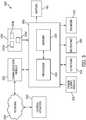
- Fig. 3illustrates a block diagram of a control system 200 associated with the cleaning machine 105 of Fig. 2 .
- the control system 200includes a controller 205 that is electrically and/or communicatively connected to a variety of modules or components of the cleaning machine 105.
- the illustrated controller 205is connected to motors 150 of the cleaning machine 105 (for driving wheels of the cleaning machine 105, one or more pumps for moving fluid within the cleaning machine 105, and the like), a power supply module 210, a user interface module 215, one or more sensors 220, and a communications module 225.
- Each of the motors 150, the power supply module 210, the user interface module 215, the sensors 220, and the communications module 225is supported upon and coupled to the cleaning machine 105.
- the controller 205can include any suitable combination of hardware and software that is operable to, among other things, control the operation of the cleaning machine 105.
- the exemplary controller 205includes a plurality of electrical and electronic components that provide power, operational control and, in some cases, protection to the components and modules within the controller 205 and/or the cleaning machine 105.
- the controller 205can include, among other things, a processing unit 230 (e.g., a microprocessor, a microcontroller, or another suitable programmable device) and a memory 235, and in some embodiments can be implemented partially or entirely on a semiconductor (e.g., a field-programmable gate array (“FPGA”)) chip, such as a chip developed through a register transfer level (“RTL”) design process.
- FPGAfield-programmable gate array
- the memory 235can include, for example, a program storage area and a data storage area.
- the program storage area and the data storage areacan include one or more different types of memory, such as read-only memory (“ROM”), random access memory (“RAM”) (e.g., dynamic RAM (“DRAM”), synchronous DRAM (“SDRAM”), etc.), electrically erasable programmable read-only memory (“EEPROM”), flash memory, a hard disk, an SD card, or other suitable magnetic, optical, physical, or electronic memory device.
- ROMread-only memory
- RAMrandom access memory
- DRAMdynamic RAM
- SDRAMsynchronous DRAM
- EEPROMelectrically erasable programmable read-only memory
- flash memorye.g., a hard disk, an SD card, or other suitable magnetic, optical, physical, or electronic memory device.
- the processing unit 230can be connected to the memory 235 for execution of software instructions that are capable of being stored in a RAM of the memory 235 (e.g., during execution), a ROM of the memory 235 (e.g., on a more permanent basis), or another non-transitory computer readable medium such as another memory or a disc.
- Software included in some implementations of the cleaning machine 105can be stored in the memory 235 of the controller 205, and can include, for example, firmware, one or more applications, program data, filters, rules, one or more program modules, and other executable instructions.
- the controller 205is configured to retrieve from memory and execute, among other things, instructions related to the control processes and methods described herein. As will be appreciated, the controller 205 can include additional, fewer, or different components.
- the illustrated power supply module 210supplies a nominal voltage to the controller 205 and other components or modules of the cleaning machine 105. More specifically, the illustrated power supply module 210 receives DC power from one or more batteries or battery packs (not shown), and outputs the nominal voltage to the controller 205 and the other components or modules of the cleaning machine 105. The power supply module 210 can receive power from other grid-independent power sources (e.g., a generator, a solar panel, etc.) in some cases, or an AC voltage from which the nominal voltage is output to the controller 205 and the other components or modules of the cleaning machine 105.
- grid-independent power sourcese.g., a generator, a solar panel, etc.
- the power supply module 210receives power from the cleaning machine 105 when the machine 105 is in operation and supplies the nominal voltage to the components and modules of the cleaning machines 105.
- one or more batteries or battery packscan be charged (e.g., using a high-speed charger) during operation of the cleaning machine 105.
- the power supply module 210does not supply the nominal voltage to the components and modules of the cleaning machine 105. Instead, the power supply module 210 receives power from the batteries or a battery pack and supplies the nominal voltage to the control system 200 (and possibly other components and modules of the machine 105).
- the user interface module 215is used to control or monitor aspects of the cleaning machine 105.
- the user interface module 215 of the illustrated embodimentis operably coupled to the controller 205 to control operation of the cleaning machine 105, and can include a combination of digital and analog input or output devices required to achieve a desired level of control and monitoring for the cleaning machine 105.
- the user interface module 215includes a display (e.g., a primary display, a secondary display, etc.) and input devices (e.g., a touch-screen display, a plurality of knobs, dials, switches, buttons, etc.).
- the displaycan be, for example, a liquid crystal display (“LCD”), a light-emitting diode (“LED”) display, an organic LED (“OLED”) display, an electroluminescent display (“ELD”), a surface-conduction electron-emitter display (“SED”), a field emission display (“FED”), a thin-film transistor (“TFT”) LCD, or a reflective bistable cholesteric display (i.e., e-paper).
- the user interface module 215also can be configured to display conditions or data associated with the cleaning machine 105 in real-time or substantially real-time. For example, the user interface module 215 can be configured to display the status of the cleaning machine 105, the position and operational status (e.g., rotating or stationary, speed, etc.) of the brush unit 130, a fluid level of the tank 125, and the like.
- the sensors 220include accelerometers 220a, position sensors 220b, and fluid level sensors 220c.
- the accelerometers 220acan sense acceleration of the cleaning machine 105 in a variety of directions (e.g., an x-direction, a y-direction, a z-direction, and the like).
- the position sensors 220bcan sense the position of the cleaning machine 105 or the position of various components of the cleaning machine 105, such as the position of the cleaning machine 105 relative to a fixed object (e.g., a wall), or the position of the brush unit 130 and/or the suction element 135 relative to the chassis 120 and/or the floor, or the speed of the cleaning machine 105 or rotational speed of the brushes.
- the level sensors 220csense a measurement of the fluid contained in the tank 125. In another example, the level sensors 220 measure an angular position of the cleaning machine 105 relative to a vertical axis. Fewer or more sensors 220 can be provided on the machine 105 as desired.
- the illustrated communications module 225is configured to connect to and communicate with other devices (e.g., a computer, another cleaning machine, etc.) through a network 240.
- the network 240can be, for example, a wide area network (“WAN”) (e.g., a global positioning system ("GPS”), a TCP/IP based network, a cellular network, such as, for example, a Global System for Mobile Communications (“GSM”) network, a General Packet Radio Service (“GPRS”) network, a Code Division Multiple Access (“CDMA”) network, an Evolution-Data Optimized (“EV-DO”) network, an Enhanced Data Rates for GSM Evolution (“EDGE”) network, a 3GSM network, a 4GSM network, a Digital Enhanced Cordless Telecommunications (“DECT”) network, a Digital AMPS (“IS-136/TDMA”) network, or an Integrated Digital Enhanced Network (“iDEN”) network, etc.).
- WANwide area network
- GSMGlobal System for Mobile Communications
- GPRSGeneral Packe
- the network 240can be a local area network (“LAN”), a neighborhood area network (“NAN”), a home area network (“HAN”), or personal area network (“PAN”) employing any of a variety of communications protocols, such as Wi-Fi, Bluetooth, ZigBee, etc. Communications through the network 240 by the communications module 225 or the controller 205 can be protected using one or more encryption techniques, such as those techniques provided in the IEEE 802.1 standard for port-based network security, pre-shared key, Extensible Authentication Protocol (“EAP”), Wired Equivalency Privacy (“WEP”), Temporal Key Integrity Protocol (“TKIP”), Wi-Fi Protected Access (“WPA”), and the like.
- EAPExtensible Authentication Protocol
- WEPWired Equivalency Privacy
- TKIPTemporal Key Integrity Protocol
- WPAWi-Fi Protected Access
- the connections between the communications module 225 and the network 240are, for example, wired connections, wireless connections, or any combination of wireless and wired connections.
- the connections between the controller 205 and the network 240 or the network communications module 225are wired connections, wireless connections, or any combination of wireless and wired connections.
- the controller 205 or communications module 225includes one or more communications ports (e.g., Ethernet, serial advanced technology attachment ("SATA”), universal serial bus (“USB”), integrated drive electronics (“IDE”), CAN bus, etc.) for transferring, receiving, or storing data associated with the cleaning machine 105 or the operation of the cleaning machine 105.
- the communications module 225communicates, through the network 240, with a central location or central control station 250 (referred to as the "central location" for ease of description).
- the central location 250can be one or a combination of a centrally located computer, a network of computers, and one or more centrally located servers, and functions to store, interpret, and communicate data from one or more cleaning machines 105.
- the central location 250can receive data from the cleaning machine 105 through the network 240, interpret the received data, and communicate the interpreted data to a user.
- the controller 205can be disconnected from the central location 250. Disconnection from the central location 250 can significantly preserve battery power. Therefore, when applicable, it may be desirable to disconnect the cleaning machine 105 from the central location 250.
- the controller 205can connect with the central location 250 periodically at least to communicate machine usage data to the central location 250. In some exemplary embodiments, the controller 205 attempts connection with the central location 250 at predetermined time periods (e.g., every one minute, every five minutes, every ten minutes, etc.). After the controller 205 successfully connects with the central location 250 (when the machine 105 is in operation or not in operation), the communications module 225 can send a message to the central location 250 through the network 240 requesting geographical positioning information, and the online geo-fence 115 is activated.
- predetermined time periodse.g., every one minute, every five minutes, every ten minutes, etc.
- the controller 205may fail to connect with the central location 250 for a variety of reasons, such as but not limited to the cleaning machine 105 being positioned 1) within the offline geo-fence 110; 2) in an out-of-network area; or 3) in an area where connection to the central location 250 is impossible.
- the controller 205When disconnected from the central location 250, the controller 205 defines the offline geo-fence 110 surrounding the cleaning machine 105.
- the offline geo-fence 110is defined using information from the sensors 220 along with a plurality of mathematical functions. After the offline geo-fence 110 is defined, the controller 205, along with the sensors 220, continually tracks the location of the cleaning machine 105 in relation to the offline geo-fence 110. If the cleaning machine 105 exits the offline geo-fence 110, the controller 205 automatically establishes (or re-establishes) communication with the central location 250.
- the central location 250geographically locates the cleaning machine 105 and can define the online geo-fence 115 around the cleaning machine 105. Thereafter, the central location 250 can continually track the location of the cleaning machine 105 relative to the online geo-fence 115. The location of the cleaning machine 105 can be tracked using one of the methods discussed above (e.g., GPS, utilization of a cellular network, utilization of a radio network, etc.).
- the central location 250can output a signal, indication, alert, or other communication (referred to as a "signal" for descriptive purposes) to one or more users that the cleaning machine 105 has exited the online geo-fence 115.
- the signal to one or more userscan take the form of one or more of an e-mail, a text message, a phone call, and other digital messages.
- the signalcan also or instead be communicated to the cleaning machine 105.
- the cleaning machine 105Upon receiving a signal from the central location 250, the cleaning machine 105 can deactivate completely, or partially deactivate while still providing geographical location information to the central location 250.
- the location informationcan be communicated to the central location 250 via the user interface module 215.
- Fig. 4is a flowchart illustrating an exemplary process 300 of geographically locating the cleaning machine 105. It will be appreciated that steps in the process 300 can differ or vary from what is described below and illustrated in the figures while remaining consistent with a system that can track the location of an apparatus.
- the controller 205defines an offline geo-fence 110 around the cleaning machine 105 at Step 305 (or alternatively, an offline geo-fence is at least partially defined by an individual setting up or configuring the cleaning machine at a facility or other location, such as by inputting a perimeter of the offline geo-fence into the memory 235 of the controller 205 via the UI module 215).
- the controller 205determines the location of the cleaning machine 105 in relation to the offline geo-fence 110 at Step 310.
- the controller 205determines whether the location of the cleaning machine 105 is inside the offline geo-fence 110 at Step 315. If the cleaning machine 105 is inside the offline geo-fence 110, the process 300 proceeds back to Step 315.
- the controller 205activates the communications module 225 at Step 320.
- the controller 205sends a message to the central location 250 through the network 240 requesting geographical position information for the machine 105.
- the central location 250determines a position of the cleaning machine 105 at Step 330 and, at Step 335, the central location 250 defines an online geo-fence 115 around the cleaning machine 105 based on preset information.
- the online geo-fence 115can be predefined based on the location of the cleaning machine 105 in relation to one or more cell towers (e.g., defining a cell location or cell ID of the cleaning machine 105) or based on one or more distances from a predefined central point.
- a cell towere.g., defining a cell location or cell ID of the cleaning machine 105
- a cellular or other signalcan be used to ping or locate the cleaning machine 105 relative to the online geo-fence 115. If the cell location or cell ID changes, the system can determine that the cleaning machine has moved outside the online geo-fence 115.
- the online geo-fence 115can be defined using only a cell location or cell ID associated with the cell tower, or based on a distance from the cell tower (e.g., within a predefined distance from the cell tower).
- the geo-fence 115When the online geo-fence 115 is defined by one or more predefined distances relative to a cell tower or another central point, the geo-fence 115 can be defined by a radial distance from the central point. Other exemplary online geo-fences 115 can be defined by polygonal shapes or non-uniform distances relative to the central point. Although the offline geo-fence 110 is illustrated as circular in Figs. 1 and 6 , and the online geo-fence 115 is illustrated as circular or square in Figs. 1 and 6 respectively, it will be appreciated that the offline geo-fence 110 and the online geo-fence 115 can have any size and shape.
- the offline geo-fence 110 and the online geo-fence 115can have the same shape (e.g., concentric shapes) or different shapes (e.g., a round or circular offline geo-fence 110 and a trapezoidal online geo-fence 115, etc.).
- the center of the offline geo-fence 110 and the online geo-fence 115can share a common central point or have different central points.
- the central location 250tracks the position of the cleaning machine 105 at Step 340 and, at Step 345, the central location 250 determines whether the cleaning machine 105 is within the online geo-fence 115. If the cleaning machine 105 is within the online geo-fence 315, the process 300 proceeds to Step 340 and continues to track the position of the cleaning machine 105. If the cleaning machine 105 is not within the online geo-fence 115 (i.e. the machine 105 is outside the online geo-fence 115), the central location 250 outputs a signal at Step 350.
- the signalcan be or include an indicator of the location of the cleaning machine 105.
- the controller 205activates the communications module 225 upon the cleaning machine 105 leaving the building. Upon activation, the communications module 225 sends a message to the central location 250 through the network 240 requesting geographical positioning information.
- the online geo-fence 115also is activated.
- the geo-location system 100defines a perimeter or area in which a cleaning machine can be used, and triggers a notification when the machine 105 is outside the perimeter.
- the overall perimeteris defined by the offline geo-fence 110 that encompasses a first area, and the online geo-fence 115 that encompasses a second, larger area.
- the first areais defined by mathematical function (e.g., a polygon) and acts as a sub-fence within the larger, second fenced area.
- the offline geo-fence 110works off the machine 105 and knowledge of the specific location of the machine 105. That is, when the machine 105 is in the first area, no machine location data is or need be communicated between the machine 105 and the central location 250. Instead, data need only be sent when the machine 105 leaves the first area.
- the illustrated system 100activates the online geo-fence 115 after the machine 105 leaves the first area defined by the offline geo-fence 110, and then actively monitors (e.g., continuously or at predetermined intervals) the machine's location.
- the systemcan notify the central location 250 or appropriate personnel when the machine 105 is located outside the offline geo-fence 110, when the machine 105 is outside the online geo-fence 115, or both.
- the systemcan deactivate the machine 105 after the machine has left the first area, the second area, or both so that loss of the asset (i.e. the machine 105) can be avoided.
- the need to transmit data through a third-party communications systemsuch as a GPS, cellular network, and the like, only exists when the machine 105 is located outside the offline geo-fence, which in some cases can be set so that any movement of the machine 105 outside of the offline geo-fence is (or is most likely) unauthorized. Until that point, communication is not required between the machine 105 and the central location 250 regarding the location of the machine 105.
- a third-party communications systemsuch as a GPS, cellular network, and the like
- the illustrated online geo-fence 115encompasses and is larger than the offline geo-fence 110, although the offline and online geo-fences 110, 115 can coincide and have the same or substantially the same perimeter. In other words, the offline and online geo-fences 110, 115 can be the same. In such cases, as soon as movement of the machine outside of the offline geo-fence 110 is detected, the online geo-fence 115 is activated, and actively monitors (e.g., continuously or at predetermined intervals) the machine's location while also sending a signal to indicate that the machine 105 has left the online geo-fence 115 and/or automatically triggering deactivation of the machine 105. In such embodiments, movement of the machine 105 through a larger online geo-fence is not required before provide notification to appropriate personnel and/or authorities that the machine 105 has been moved outside of an acceptable area (e.g., a facility or other property boundary).
- an acceptable areae.g., a facility or other property boundary
Landscapes
- Engineering & Computer Science (AREA)
- Computer Networks & Wireless Communication (AREA)
- Signal Processing (AREA)
- Mobile Radio Communication Systems (AREA)
- Burglar Alarm Systems (AREA)
- Traffic Control Systems (AREA)
- Position Fixing By Use Of Radio Waves (AREA)
- Control Of Position, Course, Altitude, Or Attitude Of Moving Bodies (AREA)
Description
- The present invention relates to a system and method of geographically locating a mobile apparatus, such as, but not limited to, a mobile cleaning machine. In particular, the present invention relates to a mobile apparatus according to the preamble part of claim 1 and a method of geo-locating a mobile apparatus according to the preamble part of claim 7. Such an apparatus and method are known from
EP 2 375 791 A2 .US 2013/015962 A1 discloses a system that conveys location information from a location tracking device to a management system over a network. - Mobile cleaning machines, such as floor cleaning machines, are generally known in the art. Many mobile cleaning machines can be commonly divided into two categories: a first category including mobile cleaning machines in which the operator is standing on the floor and walking behind the machine ("walk-behind" machines), and a second category including mobile cleaning machines in which the operator is sitting or standing on the machine itself ("ride-on" machines). Because of the mobility of such machines, it is possible for the machines to be stolen or to go missing. In some geographic locations, up to 20% of mobile cleaning machines go missing annually.
- Similar theft and loss issues are common with mobile and portable devices that, for example, are dedicated to a particular facility (e.g., building or other property) but that are susceptible to theft or loss based upon their mobile and portable nature. Examples of such other devices include forklifts, loaders, excavators, scissor lifts, lawnmowers, motorized carts, ATVs, and other wheeled or tracked vehicles.
- One solution to the theft and loss issues just described is the use of online geographical location systems. Online geographical location systems utilize online systems such as a global positioning system (GPS), a cellular network, or a radio communication network. GPSs utilize space-based satellites that communicate with a GPS receiver located on the mobile apparatus. The GPS satellites and GPS receiver communicate in order to geographically locate the GPS receiver, and thus the mobile apparatus. In contrast, geographical location systems utilizing cellular networks use the position of a cellular receiver located on the mobile apparatus relative to a plurality of cellular towers. For example, the process of triangulation or trilateration can be used to determine the position of the cellular receiver. Triangulation is the process of determining the location of the cellular receiver by measuring angles between the cellular receiver and two or more cellular towers, whereas trilateration is the process of determining the location of the cellular receiver by measuring the distances between the cellular receiver and two or more cellular towers. Geographical location systems utilizing a radio communication network use similar methods as those used with cellular networks, including but not limited to, triangulation and trilateration.
- Online geographical location systems typically require constant online communication. Constant online communication can result in excess drainage of the power source (e.g., the batteries powering the mobile apparatus). Such communication can also utilize communication resources regardless of whether the device being monitored is moving or the extent to which the device has moved. Further, constant online communication can result in excess expenses as a result of data charges.
- It is thus an object of the present invention to provide a system and method for geographically locating a mobile apparatus, such as a cleaning machine in an improved manner, such as by reducing consumption of communications resources, reducing power usage, and/or reducing charges associated with communications performed in the locating process.
- In some embodiments, the present invention provides a mobile apparatus as defined in claim 1.
- Some embodiments of the present invention provide a method as defined in claim 7.
- The dependent claims define further detailed embodiments including a a geo-location system for determining a location of a mobile apparatus.
- Other aspects of the present invention will become apparent by consideration of the detailed description and accompanying drawings.
Fig. 1 is a diagram illustrating a geographical location system embodying the invention.Fig. 2 is a perspective view of a cleaning machine used in conjunction with the geographical location system ofFig. 1 .Fig. 3 is a block diagram of a control system of the cleaning machine ofFig. 2 .Fig. 4 is a flow chart illustrating operation of the control system ofFig. 3 .Fig. 5 is a schematic representation of the geographical location system illustrating locations of a plurality of cleaning machines in a region.Fig. 6 is a schematic representation of the geographical location control system illustrating an offline geo-fence and an online geo-fence, and a cleaning machine located within the offline geo-fence.- Before any embodiments of the present invention are explained in detail, it is to be understood that the invention is not limited in its application to the details of construction and the arrangement of components set forth in the following description or illustrated in the accompanying drawings. The invention is capable of other embodiments and of being practiced or of being carried out in various ways.
- Although the invention is described herein in conjunction with a mobile cleaning machine (e.g., a floor scrubbing machine), the invention may apply to any mobile apparatus, including but not limited to a motor vehicle; a semi-truck trailer; a motorized cart; a forklift, excavator, loader, scissor lift, or other construction equipment; an all-terrain vehicle; a boat or other watercraft; a mowing device (e.g., a lawn mower), a dirt and debris pickup device (e.g., a vacuum), other wheeled or tracked vehicles. Some embodiments of the present invention also apply to other portable equipment and devices.
Figs. 1 ,5, and 6 illustrates a geographical location (geo-location)system 100 that can be used in conjunction with, and to geographically locate, a mobile or portable apparatus. As illustrated, the mobile or portable apparatus is acleaning machine 105, although the geo-location system 100 can track other apparatus. Theapparatus 105 will be referred to as a "cleaning machine" or purposes of description.- The geo-
location system 100 includes an offline geographical fence 110 (referred to as an "offline geo-fence" for purposes of description) and an online geographical fence 115 (referred to as an "online geo-fence" for purposes of description). The offline geo-fence 110 defines a first perimeter surrounding thecleaning machine 105, and the online geo-fence 115 defines a second, larger perimeter surrounding thecleaning machine 105. As illustrated, the first perimeter is circular and has a first diameter, and the second perimeter is also circular and has a second diameter. The illustrated first diameter of the offline geo-fence 110 is smaller than the second diameter of the online geo-fence 115. Although the offline geo-fence 110 and the online geo-fence 115 are described and illustrated primarily as circular perimeters, with the first perimeter being smaller than the second perimeter, the geo-fences 115 can have perimeters of any regular or irregular shape. Fig. 2 illustrates an exemplarymobile cleaning machine 105 that can be used in conjunction with thesystem 100. As illustrated, thecleaning machine 105 is a "ride-on" floor cleaning machine, although themachine 105 can take the form of a "walk-behind" cleaning machine. Thecleaning machine 105 is configured to clean a surface such as a floor and includes, among other things, a frame orchassis 120. Thechassis 120 supports several components of thecleaning machine 105, including but not limited to, atank 125, abrush unit 130, and a suction element (e.g., a squeegee assembly) 135.- The
tank 125 holds a liquid (e.g., cleaning solution including water and a cleaning agent) that is used by thecleaning machine 105 during operation. Thebrush unit 130 scrubs the surface to agitate and remove dirt or debris. Thesuction element 135 controls and draws liquid and debris up from the surface. - With continued reference to
Fig. 2 , thechassis 120 is coupled to and supported by afront castor wheel 140 and one or morerear wheels 145. The illustratedcleaning machine 105 is driven by therear wheels 145 and is steerable via thefront wheel 140, although themachine 105 can be driven with any suitable combination of drive and driven wheels. Thewheels 145 are powered by one or more motors 150 (Fig. 3 ). Although thecleaning machine 105 described and illustrated in the accompanying drawings includes thewheels cleaning machine 105 over a surface, it will be appreciated that other types of devices can be used to move thecleaning machine 105. These other types of devices can include, for example, powered or un-powered tracks. For the sake of simplicity, the term "wheel" as used herein and in the appended claims refers to any and all such moving elements. Fig. 3 illustrates a block diagram of acontrol system 200 associated with thecleaning machine 105 ofFig. 2 . Thecontrol system 200 includes acontroller 205 that is electrically and/or communicatively connected to a variety of modules or components of thecleaning machine 105. For example, the illustratedcontroller 205 is connected tomotors 150 of the cleaning machine 105 (for driving wheels of thecleaning machine 105, one or more pumps for moving fluid within the cleaningmachine 105, and the like), apower supply module 210, auser interface module 215, one ormore sensors 220, and acommunications module 225. Each of themotors 150, thepower supply module 210, theuser interface module 215, thesensors 220, and thecommunications module 225 is supported upon and coupled to thecleaning machine 105.- The
controller 205 can include any suitable combination of hardware and software that is operable to, among other things, control the operation of thecleaning machine 105. Theexemplary controller 205 includes a plurality of electrical and electronic components that provide power, operational control and, in some cases, protection to the components and modules within thecontroller 205 and/or thecleaning machine 105. For example, thecontroller 205 can include, among other things, a processing unit 230 (e.g., a microprocessor, a microcontroller, or another suitable programmable device) and amemory 235, and in some embodiments can be implemented partially or entirely on a semiconductor (e.g., a field-programmable gate array ("FPGA")) chip, such as a chip developed through a register transfer level ("RTL") design process. - The
memory 235 can include, for example, a program storage area and a data storage area. The program storage area and the data storage area can include one or more different types of memory, such as read-only memory ("ROM"), random access memory ("RAM") (e.g., dynamic RAM ("DRAM"), synchronous DRAM ("SDRAM"), etc.), electrically erasable programmable read-only memory ("EEPROM"), flash memory, a hard disk, an SD card, or other suitable magnetic, optical, physical, or electronic memory device. Theprocessing unit 230 can be connected to thememory 235 for execution of software instructions that are capable of being stored in a RAM of the memory 235 (e.g., during execution), a ROM of the memory 235 (e.g., on a more permanent basis), or another non-transitory computer readable medium such as another memory or a disc. Software included in some implementations of thecleaning machine 105 can be stored in thememory 235 of thecontroller 205, and can include, for example, firmware, one or more applications, program data, filters, rules, one or more program modules, and other executable instructions. In some embodiments, thecontroller 205 is configured to retrieve from memory and execute, among other things, instructions related to the control processes and methods described herein. As will be appreciated, thecontroller 205 can include additional, fewer, or different components. - The illustrated
power supply module 210 supplies a nominal voltage to thecontroller 205 and other components or modules of thecleaning machine 105. More specifically, the illustratedpower supply module 210 receives DC power from one or more batteries or battery packs (not shown), and outputs the nominal voltage to thecontroller 205 and the other components or modules of thecleaning machine 105. Thepower supply module 210 can receive power from other grid-independent power sources (e.g., a generator, a solar panel, etc.) in some cases, or an AC voltage from which the nominal voltage is output to thecontroller 205 and the other components or modules of thecleaning machine 105. - In some embodiments, the
power supply module 210 receives power from the cleaningmachine 105 when themachine 105 is in operation and supplies the nominal voltage to the components and modules of thecleaning machines 105. In these embodiments, one or more batteries or battery packs can be charged (e.g., using a high-speed charger) during operation of thecleaning machine 105. When thecleaning machine 105 is not in operation, thepower supply module 210 does not supply the nominal voltage to the components and modules of thecleaning machine 105. Instead, thepower supply module 210 receives power from the batteries or a battery pack and supplies the nominal voltage to the control system 200 (and possibly other components and modules of the machine 105). - The
user interface module 215 is used to control or monitor aspects of thecleaning machine 105. For example, theuser interface module 215 of the illustrated embodiment is operably coupled to thecontroller 205 to control operation of thecleaning machine 105, and can include a combination of digital and analog input or output devices required to achieve a desired level of control and monitoring for thecleaning machine 105. For example, theuser interface module 215 includes a display (e.g., a primary display, a secondary display, etc.) and input devices (e.g., a touch-screen display, a plurality of knobs, dials, switches, buttons, etc.). The display can be, for example, a liquid crystal display ("LCD"), a light-emitting diode ("LED") display, an organic LED ("OLED") display, an electroluminescent display ("ELD"), a surface-conduction electron-emitter display ("SED"), a field emission display ("FED"), a thin-film transistor ("TFT") LCD, or a reflective bistable cholesteric display (i.e., e-paper). Theuser interface module 215 also can be configured to display conditions or data associated with the cleaningmachine 105 in real-time or substantially real-time. For example, theuser interface module 215 can be configured to display the status of thecleaning machine 105, the position and operational status (e.g., rotating or stationary, speed, etc.) of thebrush unit 130, a fluid level of thetank 125, and the like. - With continued reference to the illustrated embodiment, the
sensors 220 includeaccelerometers 220a,position sensors 220b, andfluid level sensors 220c. Theaccelerometers 220a can sense acceleration of thecleaning machine 105 in a variety of directions (e.g., an x-direction, a y-direction, a z-direction, and the like). Theposition sensors 220b can sense the position of thecleaning machine 105 or the position of various components of thecleaning machine 105, such as the position of thecleaning machine 105 relative to a fixed object (e.g., a wall), or the position of thebrush unit 130 and/or thesuction element 135 relative to thechassis 120 and/or the floor, or the speed of thecleaning machine 105 or rotational speed of the brushes. In one non-limiting example, thelevel sensors 220c sense a measurement of the fluid contained in thetank 125. In another example, thelevel sensors 220 measure an angular position of thecleaning machine 105 relative to a vertical axis. Fewer ormore sensors 220 can be provided on themachine 105 as desired. - The illustrated
communications module 225 is configured to connect to and communicate with other devices (e.g., a computer, another cleaning machine, etc.) through anetwork 240. Thenetwork 240 can be, for example, a wide area network ("WAN") (e.g., a global positioning system ("GPS"), a TCP/IP based network, a cellular network, such as, for example, a Global System for Mobile Communications ("GSM") network, a General Packet Radio Service ("GPRS") network, a Code Division Multiple Access ("CDMA") network, an Evolution-Data Optimized ("EV-DO") network, an Enhanced Data Rates for GSM Evolution ("EDGE") network, a 3GSM network, a 4GSM network, a Digital Enhanced Cordless Telecommunications ("DECT") network, a Digital AMPS ("IS-136/TDMA") network, or an Integrated Digital Enhanced Network ("iDEN") network, etc.). - The
network 240 can be a local area network ("LAN"), a neighborhood area network ("NAN"), a home area network ("HAN"), or personal area network ("PAN") employing any of a variety of communications protocols, such as Wi-Fi, Bluetooth, ZigBee, etc. Communications through thenetwork 240 by thecommunications module 225 or thecontroller 205 can be protected using one or more encryption techniques, such as those techniques provided in the IEEE 802.1 standard for port-based network security, pre-shared key, Extensible Authentication Protocol ("EAP"), Wired Equivalency Privacy ("WEP"), Temporal Key Integrity Protocol ("TKIP"), Wi-Fi Protected Access ("WPA"), and the like. - The connections between the
communications module 225 and thenetwork 240 are, for example, wired connections, wireless connections, or any combination of wireless and wired connections. Similarly, the connections between thecontroller 205 and thenetwork 240 or thenetwork communications module 225 are wired connections, wireless connections, or any combination of wireless and wired connections. In some embodiments, thecontroller 205 orcommunications module 225 includes one or more communications ports (e.g., Ethernet, serial advanced technology attachment ("SATA"), universal serial bus ("USB"), integrated drive electronics ("IDE"), CAN bus, etc.) for transferring, receiving, or storing data associated with the cleaningmachine 105 or the operation of thecleaning machine 105. - The
communications module 225 communicates, through thenetwork 240, with a central location or central control station 250 (referred to as the "central location" for ease of description). Thecentral location 250 can be one or a combination of a centrally located computer, a network of computers, and one or more centrally located servers, and functions to store, interpret, and communicate data from one ormore cleaning machines 105. For example, thecentral location 250 can receive data from the cleaningmachine 105 through thenetwork 240, interpret the received data, and communicate the interpreted data to a user. - During normal operation, the
controller 205 can be disconnected from thecentral location 250. Disconnection from thecentral location 250 can significantly preserve battery power. Therefore, when applicable, it may be desirable to disconnect thecleaning machine 105 from thecentral location 250. - In some constructions, the
controller 205 can connect with thecentral location 250 periodically at least to communicate machine usage data to thecentral location 250. In some exemplary embodiments, thecontroller 205 attempts connection with thecentral location 250 at predetermined time periods (e.g., every one minute, every five minutes, every ten minutes, etc.). After thecontroller 205 successfully connects with the central location 250 (when themachine 105 is in operation or not in operation), thecommunications module 225 can send a message to thecentral location 250 through thenetwork 240 requesting geographical positioning information, and the online geo-fence 115 is activated. Thecontroller 205 may fail to connect with thecentral location 250 for a variety of reasons, such as but not limited to thecleaning machine 105 being positioned 1) within the offline geo-fence 110; 2) in an out-of-network area; or 3) in an area where connection to thecentral location 250 is impossible. - When disconnected from the
central location 250, thecontroller 205 defines the offline geo-fence 110 surrounding the cleaningmachine 105. In some embodiments, the offline geo-fence 110 is defined using information from thesensors 220 along with a plurality of mathematical functions. After the offline geo-fence 110 is defined, thecontroller 205, along with thesensors 220, continually tracks the location of thecleaning machine 105 in relation to the offline geo-fence 110. If thecleaning machine 105 exits the offline geo-fence 110, thecontroller 205 automatically establishes (or re-establishes) communication with thecentral location 250. - When the communication link between the
controller 205 andcentral location 250 has been enabled, thecentral location 250 geographically locates thecleaning machine 105 and can define the online geo-fence 115 around the cleaningmachine 105. Thereafter, thecentral location 250 can continually track the location of thecleaning machine 105 relative to the online geo-fence 115. The location of thecleaning machine 105 can be tracked using one of the methods discussed above (e.g., GPS, utilization of a cellular network, utilization of a radio network, etc.). If thecleaning machine 105 exits the online geo-fence 115, thecentral location 250 can output a signal, indication, alert, or other communication (referred to as a "signal" for descriptive purposes) to one or more users that thecleaning machine 105 has exited the online geo-fence 115. The signal to one or more users can take the form of one or more of an e-mail, a text message, a phone call, and other digital messages. - The signal can also or instead be communicated to the
cleaning machine 105. Upon receiving a signal from thecentral location 250, the cleaningmachine 105 can deactivate completely, or partially deactivate while still providing geographical location information to thecentral location 250. For example, the location information can be communicated to thecentral location 250 via theuser interface module 215. Fig. 4 is a flowchart illustrating anexemplary process 300 of geographically locating thecleaning machine 105. It will be appreciated that steps in theprocess 300 can differ or vary from what is described below and illustrated in the figures while remaining consistent with a system that can track the location of an apparatus.- With reference to
Figs. 4 and6 , thecontroller 205 defines an offline geo-fence 110 around the cleaningmachine 105 at Step 305 (or alternatively, an offline geo-fence is at least partially defined by an individual setting up or configuring the cleaning machine at a facility or other location, such as by inputting a perimeter of the offline geo-fence into thememory 235 of thecontroller 205 via the UI module 215). Atstep 310, thecontroller 205 determines the location of thecleaning machine 105 in relation to the offline geo-fence 110 atStep 310. Thecontroller 205 determines whether the location of thecleaning machine 105 is inside the offline geo-fence 110 atStep 315. If thecleaning machine 105 is inside the offline geo-fence 110, theprocess 300 proceeds back toStep 315. - If the
cleaning machine 105 is not inside the offline geo-fence 110 (i.e. themachine 105 is outside the offline geo-fence 110), thecontroller 205 activates thecommunications module 225 atStep 320. AtStep 325, thecontroller 205 sends a message to thecentral location 250 through thenetwork 240 requesting geographical position information for themachine 105. Thecentral location 250 determines a position of thecleaning machine 105 atStep 330 and, atStep 335, thecentral location 250 defines an online geo-fence 115 around the cleaningmachine 105 based on preset information. For example, the online geo-fence 115 can be predefined based on the location of thecleaning machine 105 in relation to one or more cell towers (e.g., defining a cell location or cell ID of the cleaning machine 105) or based on one or more distances from a predefined central point. In the cell tower example, a cellular or other signal can be used to ping or locate thecleaning machine 105 relative to the online geo-fence 115. If the cell location or cell ID changes, the system can determine that the cleaning machine has moved outside the online geo-fence 115. The online geo-fence 115 can be defined using only a cell location or cell ID associated with the cell tower, or based on a distance from the cell tower (e.g., within a predefined distance from the cell tower). - When the online geo-
fence 115 is defined by one or more predefined distances relative to a cell tower or another central point, the geo-fence 115 can be defined by a radial distance from the central point. Other exemplary online geo-fences 115 can be defined by polygonal shapes or non-uniform distances relative to the central point. Although the offline geo-fence 110 is illustrated as circular inFigs. 1 and6 , and the online geo-fence 115 is illustrated as circular or square inFigs. 1 and6 respectively, it will be appreciated that the offline geo-fence 110 and the online geo-fence 115 can have any size and shape. The offline geo-fence 110 and the online geo-fence 115 can have the same shape (e.g., concentric shapes) or different shapes (e.g., a round or circular offline geo-fence 110 and a trapezoidal online geo-fence 115, etc.). In addition, the center of the offline geo-fence 110 and the online geo-fence 115 can share a common central point or have different central points. - The
central location 250 tracks the position of thecleaning machine 105 atStep 340 and, atStep 345, thecentral location 250 determines whether the cleaningmachine 105 is within the online geo-fence 115. If thecleaning machine 105 is within the online geo-fence 315, theprocess 300 proceeds to Step 340 and continues to track the position of thecleaning machine 105. If thecleaning machine 105 is not within the online geo-fence 115 (i.e. themachine 105 is outside the online geo-fence 115), thecentral location 250 outputs a signal atStep 350. For example, the signal can be or include an indicator of the location of thecleaning machine 105. - When the offline geo-
fence 110 is defined by the perimeter of a building, for example, thecontroller 205 activates thecommunications module 225 upon thecleaning machine 105 leaving the building. Upon activation, thecommunications module 225 sends a message to thecentral location 250 through thenetwork 240 requesting geographical positioning information. The online geo-fence 115 also is activated. - The geo-
location system 100 defines a perimeter or area in which a cleaning machine can be used, and triggers a notification when themachine 105 is outside the perimeter. The overall perimeter is defined by the offline geo-fence 110 that encompasses a first area, and the online geo-fence 115 that encompasses a second, larger area. In some embodiments, the first area is defined by mathematical function (e.g., a polygon) and acts as a sub-fence within the larger, second fenced area. The offline geo-fence 110 works off themachine 105 and knowledge of the specific location of themachine 105. That is, when themachine 105 is in the first area, no machine location data is or need be communicated between themachine 105 and thecentral location 250. Instead, data need only be sent when themachine 105 leaves the first area. - The illustrated
system 100 activates the online geo-fence 115 after themachine 105 leaves the first area defined by the offline geo-fence 110, and then actively monitors (e.g., continuously or at predetermined intervals) the machine's location. The system can notify thecentral location 250 or appropriate personnel when themachine 105 is located outside the offline geo-fence 110, when themachine 105 is outside the online geo-fence 115, or both. In some circumstances, the system can deactivate themachine 105 after the machine has left the first area, the second area, or both so that loss of the asset (i.e. the machine 105) can be avoided. - With the geo-
location system 100, the need to transmit data through a third-party communications system, such as a GPS, cellular network, and the like, only exists when themachine 105 is located outside the offline geo-fence, which in some cases can be set so that any movement of themachine 105 outside of the offline geo-fence is (or is most likely) unauthorized. Until that point, communication is not required between themachine 105 and thecentral location 250 regarding the location of themachine 105. Even if location data communication is provided, (e.g., when thecentral location 250 is owned and/or controlled by personnel located within the perimeter defined by the offline geo-fence 110), the need and expense associated with a third-party communications system would only exist if, for example, the machine is stolen or otherwise moved from the within the offline geo-fence 110 without authorization. - The illustrated online geo-
fence 115 encompasses and is larger than the offline geo-fence 110, although the offline and online geo-fences fences fence 110 is detected, the online geo-fence 115 is activated, and actively monitors (e.g., continuously or at predetermined intervals) the machine's location while also sending a signal to indicate that themachine 105 has left the online geo-fence 115 and/or automatically triggering deactivation of themachine 105. In such embodiments, movement of themachine 105 through a larger online geo-fence is not required before provide notification to appropriate personnel and/or authorities that themachine 105 has been moved outside of an acceptable area (e.g., a facility or other property boundary). - The scope of the invention is set forth in the following claims.
Claims (15)
- A mobile apparatus (105) operable to communicate with a central location (250), the mobile apparatus (105) comprising:a chassis (120);a communications module (225); andcharacterized bya controller (205) including a processor (230) and memory (235), the processor (230) programmed to perform instructions stored in the memory (235), the instructions includingdefining an offline perimeter (110) when the mobile apparatus (105) is disconnected from the central location (250) to enable tracking of the chassis (120) relative to the offline perimeter,locating a chassis position in relation to the offline perimeter (110), determining that the chassis position is outside the offline perimeter (110), and upon the determination,establishing communication between the mobile apparatus (105) and the central location (250) over a network (240) via the communication module (225) and causing activation of an online perimeter (115) by establishing communication to cause tracking by the central location (250) of the chassis (120) relative to the online perimeter (115), the online perimeter (115) having a larger area than the offline perimeter (110),receiving an indication via the network (240) that the chassis (120) is located outside the online perimeter (115), andtransmitting a signal reflecting a location of the mobile apparatus (105) outside of the online perimeter (115) upon receiving the indication.
- The mobile apparatus (105) of claim 1, wherein the offline perimeter (110) is defined by a mathematical function.
- The mobile apparatus (105) of claim 2, wherein the online perimeter (115) is defined by one of a global positioning system, a cellular network, and a radio communication network.
- The mobile apparatus (105) of claim 1, wherein the signal is a notification that the chassis (120) is located outside the online perimeter (115).
- The mobile apparatus (105) of claim 1, wherein the signal deactivates the mobile apparatus (105).
- The mobile apparatus (105) of claim 1, wherein the mobile apparatus (105) is a floor cleaning machine.
- A method of geo-locating a mobile apparatus (105) including a chassis (120), the method beingcharacterized by
defining by a controller (205) an offline perimeter (110) when the mobile apparatus (105) is disconnected from a central location (250);
monitoring by the mobile apparatus (105) the position of the chassis (120) in relation to the offline perimeter (110);
determining by the mobile apparatus (105) that the chassis (120) is located outside the offline perimeter (110), and upon the determination,establishing by the mobile apparatus (105) communication between the mobile apparatus (105) and a central location (250) over a network (240), anddefining by the central location (250) an online perimeter (115), after establishing communication, to enable tracking of the chassis (120) relative to the online perimeter (115), the online perimeter (115) having a larger area than the offline perimeter (110),monitoring by the central location (250) the position of the chassis (120) in relation to the online perimeter (115),determining by the central location (250) that the chassis (120) is located outside of the online perimeter (115), andtransmitting by the central location (250) a signal that the chassis (120) is located outside of the online perimeter (115), wherein the signal indicates a location of the mobile apparatus (105) outside of the online perimeter (115). - The method of claim 7, wherein the offline perimeter (110) is defined by a mathematical function.
- The method of claim 7, wherein the online perimeter (115) is defined by one of a global positioning system, a cellular network, and a radio communication network.
- The method of claim 7, further comprising notifying by the central location (250) one or both of a server and an end user that the chassis (120) is located outside the online perimeter (115).
- The method of claim 7, further comprising deactivating the mobile apparatus (105) based upon determining that the chassis (120) is located outside of the online perimeter (115).
- A geo-location system for determining a location of a mobile apparatus (105), the system comprising:a mobile apparatus (105) according to claim 1; anda central location (250) including a network communications module (240) and a positioning module.
- The system of claim 12, wherein the offline perimeter (110) is defined by a mathematical function; and/or
wherein the online perimeter (115) is defined by one of a global positioning system, a cellular network, and a radio communication network. - The system of claim 12, wherein the signal is a notification that the mobile apparatus (105) is located outside the online perimeter (115).
- The system of claim 12, wherein the signal deactivates the mobile apparatus (105).
Applications Claiming Priority (2)
| Application Number | Priority Date | Filing Date | Title |
|---|---|---|---|
| US201461925911P | 2014-01-10 | 2014-01-10 | |
| PCT/US2015/010882WO2015106144A1 (en) | 2014-01-10 | 2015-01-09 | System and method of geo-locating mobile apparatus |
Publications (3)
| Publication Number | Publication Date |
|---|---|
| EP3092629A1 EP3092629A1 (en) | 2016-11-16 |
| EP3092629A4 EP3092629A4 (en) | 2017-09-06 |
| EP3092629B1true EP3092629B1 (en) | 2021-03-31 |
Family
ID=53524383
Family Applications (1)
| Application Number | Title | Priority Date | Filing Date |
|---|---|---|---|
| EP15735561.1AActiveEP3092629B1 (en) | 2014-01-10 | 2015-01-09 | System and method of geo-locating mobile apparatus |
Country Status (8)
| Country | Link |
|---|---|
| US (2) | US10034143B2 (en) |
| EP (1) | EP3092629B1 (en) |
| JP (1) | JP6697390B2 (en) |
| CN (1) | CN106062838B (en) |
| AU (1) | AU2015204552B2 (en) |
| CA (1) | CA2935385A1 (en) |
| DK (1) | DK3092629T3 (en) |
| WO (1) | WO2015106144A1 (en) |
Families Citing this family (1)
| Publication number | Priority date | Publication date | Assignee | Title |
|---|---|---|---|---|
| US20210137338A1 (en) | 2019-11-13 | 2021-05-13 | Emerson Electric Co. | Vacuum cleaner motor assemblies and methods of operating same |
Family Cites Families (25)
| Publication number | Priority date | Publication date | Assignee | Title |
|---|---|---|---|---|
| JPH0877471A (en) | 1994-09-01 | 1996-03-22 | Fujitsu Ten Ltd | Security system |
| JP2000138961A (en)* | 1998-11-04 | 2000-05-16 | Funai Electric Co Ltd | Phs portable terminal with gps function |
| US20020152576A1 (en) | 2001-04-20 | 2002-10-24 | Pro-Team, Inc. An Idaho Corporation | Method and apparatus for improved use, maintenance and management of floor maintenance equipment |
| JP2003065771A (en) | 2001-08-24 | 2003-03-05 | Toyota Industries Corp | Position detecting system for mobile object |
| US6665613B2 (en)* | 2001-09-25 | 2003-12-16 | Lojack Corporation | Method of and apparatus for dynamically GoeFencing movable vehicle and other equipment and the like |
| RU2308045C2 (en)* | 2002-05-07 | 2007-10-10 | Агротек Корпорейшн | Method and system for tracking |
| US8428778B2 (en)* | 2002-09-13 | 2013-04-23 | Irobot Corporation | Navigational control system for a robotic device |
| JP2005211359A (en) | 2004-01-30 | 2005-08-11 | Funai Electric Co Ltd | Autonomous traveling robot cleaner system |
| EP1810257B1 (en) | 2004-11-12 | 2011-09-28 | Tennant Company | Mobile floor cleaner data communication |
| US7385499B2 (en)* | 2004-12-17 | 2008-06-10 | United Parcel Service Of America, Inc. | Item-based monitoring systems and methods |
| US7877166B2 (en) | 2005-06-28 | 2011-01-25 | S.C. Johnson & Son, Inc. | RFID navigational system for robotic floor treater |
| US8593276B2 (en)* | 2006-02-01 | 2013-11-26 | Qualcomm Incorporated | Method and apparatus for asset geofencing |
| US20070194881A1 (en)* | 2006-02-07 | 2007-08-23 | Schwarz Stanley G | Enforcing payment schedules |
| EP3699012B1 (en) | 2006-12-13 | 2024-05-08 | Crown Equipment Corporation | Fleet management system |
| US8002181B2 (en) | 2007-08-24 | 2011-08-23 | Wal-Mart Stores, Inc. | RFID promotional compliance |
| JP5290611B2 (en)* | 2008-04-10 | 2013-09-18 | 株式会社日立産機システム | POSITIONING SYSTEM, POSITIONING SYSTEM CONTROL METHOD, AND COMMUNICATION TERMINAL |
| US8620393B2 (en) | 2008-06-13 | 2013-12-31 | Qualcomm Incorporated | Optimizing battery life and network resources during position location tracking scenario |
| KR101531056B1 (en) | 2008-12-04 | 2015-06-23 | 두산인프라코어 주식회사 | Communication method for monitoring the position of a construction machine |
| US8018329B2 (en)* | 2008-12-12 | 2011-09-13 | Gordon * Howard Associates, Inc. | Automated geo-fence boundary configuration and activation |
| US20110148626A1 (en)* | 2009-01-12 | 2011-06-23 | Acevedo William C | GPS Device and Portal |
| US8774970B2 (en)* | 2009-06-11 | 2014-07-08 | S.C. Johnson & Son, Inc. | Trainable multi-mode floor cleaning device |
| US8595892B1 (en) | 2010-08-02 | 2013-12-03 | Wilson E. Everette, Jr. | Ultrasonic floor cleaner and scrubber |
| WO2012112091A1 (en)* | 2011-02-17 | 2012-08-23 | Telefonaktiebolaget L M Ericsson (Publ) | System, servers, methods and computer programs for machine-to-machine equipment management |
| US20130015962A1 (en)* | 2011-07-12 | 2013-01-17 | Rodger Steven Dailey | Systems and methods for using gps tracking data |
| WO2013044070A2 (en)* | 2011-09-21 | 2013-03-28 | Jeff Thramann | Systems and methods for tracking mobile devices |
- 2015
- 2015-01-09EPEP15735561.1Apatent/EP3092629B1/enactiveActive
- 2015-01-09WOPCT/US2015/010882patent/WO2015106144A1/enactiveApplication Filing
- 2015-01-09CNCN201580004301.4Apatent/CN106062838B/enactiveActive
- 2015-01-09DKDK15735561.1Tpatent/DK3092629T3/enactive
- 2015-01-09AUAU2015204552Apatent/AU2015204552B2/enactiveActive
- 2015-01-09USUS15/110,917patent/US10034143B2/enactiveActive
- 2015-01-09JPJP2016545891Apatent/JP6697390B2/ennot_activeExpired - Fee Related
- 2015-01-09CACA2935385Apatent/CA2935385A1/ennot_activeAbandoned
- 2018
- 2018-07-24USUS16/043,763patent/US10356576B2/enactiveActive
Non-Patent Citations (1)
| Title |
|---|
| None* |
Also Published As
| Publication number | Publication date |
|---|---|
| US10356576B2 (en) | 2019-07-16 |
| CN106062838B (en) | 2019-02-15 |
| WO2015106144A1 (en) | 2015-07-16 |
| EP3092629A4 (en) | 2017-09-06 |
| CN106062838A (en) | 2016-10-26 |
| AU2015204552A1 (en) | 2016-07-14 |
| CA2935385A1 (en) | 2015-07-16 |
| EP3092629A1 (en) | 2016-11-16 |
| US20160345139A1 (en) | 2016-11-24 |
| DK3092629T3 (en) | 2021-06-21 |
| JP6697390B2 (en) | 2020-05-20 |
| US20190090104A1 (en) | 2019-03-21 |
| AU2015204552B2 (en) | 2019-06-06 |
| US10034143B2 (en) | 2018-07-24 |
| JP2017508134A (en) | 2017-03-23 |
Similar Documents
| Publication | Publication Date | Title |
|---|---|---|
| CA2935391C (en) | Cleaning apparatus data management system and method | |
| JP6759111B2 (en) | Methods performed by mobile lawn mower robots, methods performed by beacons, and lawn mower systems | |
| US9475196B2 (en) | Detachable user interface for a robotic vehicle | |
| US10405488B2 (en) | Zone control system for a robotic vehicle | |
| US9563204B2 (en) | Mower with object detection system | |
| US20120259537A1 (en) | Moving Geofence for Machine Tracking in Agriculture | |
| JP6125038B2 (en) | Reporting system | |
| US20130117867A1 (en) | Theft Prevention for Networked Robot | |
| EP2369908A1 (en) | An autonomous robotic lawn mower and a method for establishing a wireless communication link between the lawn mower and a user | |
| US11161412B2 (en) | Electric scooter piloting method, electric scooter and storage medium | |
| WO2014027946A1 (en) | Boundary definition system for a robotic vehicle | |
| US20170320215A1 (en) | Remote interaction with a robotic vehicle | |
| US10356576B2 (en) | System and method of geo-locating mobile apparatus | |
| CN103217976A (en) | Self-driven shift unit | |
| CA3129739A1 (en) | Remote vehicle state estimation systems and methods | |
| US20190373408A1 (en) | Method and system for monitoring the position of an object | |
| US20240099535A1 (en) | Floor Cleaning Machines Having Intelligent Systems, Associated Sub-Assemblies Incorporating Intelligent Systems, and Associated Methods of Use | |
| WO2003078220A1 (en) | Data sharing method and apparatus using a non-permanent communication link | |
| US11341787B2 (en) | Device management | |
| EP4340296A1 (en) | Geration of a cryptography key for a robotic garden tool | |
| CN118050679A (en) | Determining placement position of base station equipment used for robotic garden tool |
Legal Events
| Date | Code | Title | Description |
|---|---|---|---|
| PUAI | Public reference made under article 153(3) epc to a published international application that has entered the european phase | Free format text:ORIGINAL CODE: 0009012 | |
| 17P | Request for examination filed | Effective date:20160629 | |
| AK | Designated contracting states | Kind code of ref document:A1 Designated state(s):AL AT BE BG CH CY CZ DE DK EE ES FI FR GB GR HR HU IE IS IT LI LT LU LV MC MK MT NL NO PL PT RO RS SE SI SK SM TR | |
| AX | Request for extension of the european patent | Extension state:BA ME | |
| DAX | Request for extension of the european patent (deleted) | ||
| A4 | Supplementary search report drawn up and despatched | Effective date:20170803 | |
| RIC1 | Information provided on ipc code assigned before grant | Ipc:H04W 4/04 20090101ALI20170728BHEP Ipc:H04W 64/00 20090101ALI20170728BHEP Ipc:G08B 13/14 20060101AFI20170728BHEP Ipc:H04W 4/02 20090101ALI20170728BHEP | |
| STAA | Information on the status of an ep patent application or granted ep patent | Free format text:STATUS: EXAMINATION IS IN PROGRESS | |
| 17Q | First examination report despatched | Effective date:20190409 | |
| GRAP | Despatch of communication of intention to grant a patent | Free format text:ORIGINAL CODE: EPIDOSNIGR1 | |
| STAA | Information on the status of an ep patent application or granted ep patent | Free format text:STATUS: GRANT OF PATENT IS INTENDED | |
| RIC1 | Information provided on ipc code assigned before grant | Ipc:G08B 13/14 20060101AFI20200924BHEP Ipc:H04W 4/02 20180101ALI20200924BHEP | |
| INTG | Intention to grant announced | Effective date:20201021 | |
| RIN1 | Information on inventor provided before grant (corrected) | Inventor name:GATTER, HEINZ | |
| GRAS | Grant fee paid | Free format text:ORIGINAL CODE: EPIDOSNIGR3 | |
| GRAA | (expected) grant | Free format text:ORIGINAL CODE: 0009210 | |
| STAA | Information on the status of an ep patent application or granted ep patent | Free format text:STATUS: THE PATENT HAS BEEN GRANTED | |
| AK | Designated contracting states | Kind code of ref document:B1 Designated state(s):AL AT BE BG CH CY CZ DE DK EE ES FI FR GB GR HR HU IE IS IT LI LT LU LV MC MK MT NL NO PL PT RO RS SE SI SK SM TR | |
| REG | Reference to a national code | Ref country code:GB Ref legal event code:FG4D Ref country code:CH Ref legal event code:EP | |
| REG | Reference to a national code | Ref country code:AT Ref legal event code:REF Ref document number:1377808 Country of ref document:AT Kind code of ref document:T Effective date:20210415 | |
| REG | Reference to a national code | Ref country code:DE Ref legal event code:R096 Ref document number:602015067458 Country of ref document:DE | |
| REG | Reference to a national code | Ref country code:IE Ref legal event code:FG4D | |
| REG | Reference to a national code | Ref country code:DK Ref legal event code:T3 Effective date:20210614 | |
| REG | Reference to a national code | Ref country code:LT Ref legal event code:MG9D | |
| PG25 | Lapsed in a contracting state [announced via postgrant information from national office to epo] | Ref country code:NO Free format text:LAPSE BECAUSE OF FAILURE TO SUBMIT A TRANSLATION OF THE DESCRIPTION OR TO PAY THE FEE WITHIN THE PRESCRIBED TIME-LIMIT Effective date:20210630 Ref country code:BG Free format text:LAPSE BECAUSE OF FAILURE TO SUBMIT A TRANSLATION OF THE DESCRIPTION OR TO PAY THE FEE WITHIN THE PRESCRIBED TIME-LIMIT Effective date:20210630 Ref country code:HR Free format text:LAPSE BECAUSE OF FAILURE TO SUBMIT A TRANSLATION OF THE DESCRIPTION OR TO PAY THE FEE WITHIN THE PRESCRIBED TIME-LIMIT Effective date:20210331 Ref country code:FI Free format text:LAPSE BECAUSE OF FAILURE TO SUBMIT A TRANSLATION OF THE DESCRIPTION OR TO PAY THE FEE WITHIN THE PRESCRIBED TIME-LIMIT Effective date:20210331 | |
| PG25 | Lapsed in a contracting state [announced via postgrant information from national office to epo] | Ref country code:SE Free format text:LAPSE BECAUSE OF FAILURE TO SUBMIT A TRANSLATION OF THE DESCRIPTION OR TO PAY THE FEE WITHIN THE PRESCRIBED TIME-LIMIT Effective date:20210331 Ref country code:RS Free format text:LAPSE BECAUSE OF FAILURE TO SUBMIT A TRANSLATION OF THE DESCRIPTION OR TO PAY THE FEE WITHIN THE PRESCRIBED TIME-LIMIT Effective date:20210331 Ref country code:LV Free format text:LAPSE BECAUSE OF FAILURE TO SUBMIT A TRANSLATION OF THE DESCRIPTION OR TO PAY THE FEE WITHIN THE PRESCRIBED TIME-LIMIT Effective date:20210331 | |
| REG | Reference to a national code | Ref country code:NL Ref legal event code:MP Effective date:20210331 | |
| REG | Reference to a national code | Ref country code:AT Ref legal event code:MK05 Ref document number:1377808 Country of ref document:AT Kind code of ref document:T Effective date:20210331 | |
| PG25 | Lapsed in a contracting state [announced via postgrant information from national office to epo] | Ref country code:AT Free format text:LAPSE BECAUSE OF FAILURE TO SUBMIT A TRANSLATION OF THE DESCRIPTION OR TO PAY THE FEE WITHIN THE PRESCRIBED TIME-LIMIT Effective date:20210331 Ref country code:SM Free format text:LAPSE BECAUSE OF FAILURE TO SUBMIT A TRANSLATION OF THE DESCRIPTION OR TO PAY THE FEE WITHIN THE PRESCRIBED TIME-LIMIT Effective date:20210331 Ref country code:NL Free format text:LAPSE BECAUSE OF FAILURE TO SUBMIT A TRANSLATION OF THE DESCRIPTION OR TO PAY THE FEE WITHIN THE PRESCRIBED TIME-LIMIT Effective date:20210331 Ref country code:LT Free format text:LAPSE BECAUSE OF FAILURE TO SUBMIT A TRANSLATION OF THE DESCRIPTION OR TO PAY THE FEE WITHIN THE PRESCRIBED TIME-LIMIT Effective date:20210331 Ref country code:EE Free format text:LAPSE BECAUSE OF FAILURE TO SUBMIT A TRANSLATION OF THE DESCRIPTION OR TO PAY THE FEE WITHIN THE PRESCRIBED TIME-LIMIT Effective date:20210331 Ref country code:CZ Free format text:LAPSE BECAUSE OF FAILURE TO SUBMIT A TRANSLATION OF THE DESCRIPTION OR TO PAY THE FEE WITHIN THE PRESCRIBED TIME-LIMIT Effective date:20210331 | |
| PG25 | Lapsed in a contracting state [announced via postgrant information from national office to epo] | Ref country code:SK Free format text:LAPSE BECAUSE OF FAILURE TO SUBMIT A TRANSLATION OF THE DESCRIPTION OR TO PAY THE FEE WITHIN THE PRESCRIBED TIME-LIMIT Effective date:20210331 Ref country code:RO Free format text:LAPSE BECAUSE OF FAILURE TO SUBMIT A TRANSLATION OF THE DESCRIPTION OR TO PAY THE FEE WITHIN THE PRESCRIBED TIME-LIMIT Effective date:20210331 Ref country code:PL Free format text:LAPSE BECAUSE OF FAILURE TO SUBMIT A TRANSLATION OF THE DESCRIPTION OR TO PAY THE FEE WITHIN THE PRESCRIBED TIME-LIMIT Effective date:20210331 Ref country code:PT Free format text:LAPSE BECAUSE OF FAILURE TO SUBMIT A TRANSLATION OF THE DESCRIPTION OR TO PAY THE FEE WITHIN THE PRESCRIBED TIME-LIMIT Effective date:20210802 Ref country code:ES Free format text:LAPSE BECAUSE OF FAILURE TO SUBMIT A TRANSLATION OF THE DESCRIPTION OR TO PAY THE FEE WITHIN THE PRESCRIBED TIME-LIMIT Effective date:20210331 Ref country code:IS Free format text:LAPSE BECAUSE OF FAILURE TO SUBMIT A TRANSLATION OF THE DESCRIPTION OR TO PAY THE FEE WITHIN THE PRESCRIBED TIME-LIMIT Effective date:20210731 | |
| REG | Reference to a national code | Ref country code:DE Ref legal event code:R097 Ref document number:602015067458 Country of ref document:DE | |
| PG25 | Lapsed in a contracting state [announced via postgrant information from national office to epo] | Ref country code:AL Free format text:LAPSE BECAUSE OF FAILURE TO SUBMIT A TRANSLATION OF THE DESCRIPTION OR TO PAY THE FEE WITHIN THE PRESCRIBED TIME-LIMIT Effective date:20210331 | |
| PLBE | No opposition filed within time limit | Free format text:ORIGINAL CODE: 0009261 | |
| STAA | Information on the status of an ep patent application or granted ep patent | Free format text:STATUS: NO OPPOSITION FILED WITHIN TIME LIMIT | |
| 26N | No opposition filed | Effective date:20220104 | |
| PG25 | Lapsed in a contracting state [announced via postgrant information from national office to epo] | Ref country code:IS Free format text:LAPSE BECAUSE OF FAILURE TO SUBMIT A TRANSLATION OF THE DESCRIPTION OR TO PAY THE FEE WITHIN THE PRESCRIBED TIME-LIMIT Effective date:20210731 | |
| PG25 | Lapsed in a contracting state [announced via postgrant information from national office to epo] | Ref country code:MC Free format text:LAPSE BECAUSE OF FAILURE TO SUBMIT A TRANSLATION OF THE DESCRIPTION OR TO PAY THE FEE WITHIN THE PRESCRIBED TIME-LIMIT Effective date:20210331 | |
| REG | Reference to a national code | Ref country code:BE Ref legal event code:MM Effective date:20220131 | |
| PG25 | Lapsed in a contracting state [announced via postgrant information from national office to epo] | Ref country code:LU Free format text:LAPSE BECAUSE OF NON-PAYMENT OF DUE FEES Effective date:20220109 | |
| PG25 | Lapsed in a contracting state [announced via postgrant information from national office to epo] | Ref country code:BE Free format text:LAPSE BECAUSE OF NON-PAYMENT OF DUE FEES Effective date:20220131 | |
| PG25 | Lapsed in a contracting state [announced via postgrant information from national office to epo] | Ref country code:IE Free format text:LAPSE BECAUSE OF NON-PAYMENT OF DUE FEES Effective date:20220109 | |
| P01 | Opt-out of the competence of the unified patent court (upc) registered | Effective date:20230509 | |
| REG | Reference to a national code | Ref country code:DE Ref legal event code:R082 Ref document number:602015067458 Country of ref document:DE Representative=s name:LKGLOBAL LORENZ UND KOPF PATENTANWALT, ATTORNE, DE | |
| PG25 | Lapsed in a contracting state [announced via postgrant information from national office to epo] | Ref country code:HU Free format text:LAPSE BECAUSE OF FAILURE TO SUBMIT A TRANSLATION OF THE DESCRIPTION OR TO PAY THE FEE WITHIN THE PRESCRIBED TIME-LIMIT; INVALID AB INITIO Effective date:20150109 | |
| PG25 | Lapsed in a contracting state [announced via postgrant information from national office to epo] | Ref country code:MK Free format text:LAPSE BECAUSE OF FAILURE TO SUBMIT A TRANSLATION OF THE DESCRIPTION OR TO PAY THE FEE WITHIN THE PRESCRIBED TIME-LIMIT Effective date:20210331 Ref country code:CY Free format text:LAPSE BECAUSE OF FAILURE TO SUBMIT A TRANSLATION OF THE DESCRIPTION OR TO PAY THE FEE WITHIN THE PRESCRIBED TIME-LIMIT Effective date:20210331 | |
| PG25 | Lapsed in a contracting state [announced via postgrant information from national office to epo] | Ref country code:MT Free format text:LAPSE BECAUSE OF FAILURE TO SUBMIT A TRANSLATION OF THE DESCRIPTION OR TO PAY THE FEE WITHIN THE PRESCRIBED TIME-LIMIT Effective date:20210331 | |
| PG25 | Lapsed in a contracting state [announced via postgrant information from national office to epo] | Ref country code:GR Free format text:LAPSE BECAUSE OF NON-PAYMENT OF DUE FEES Effective date:20210331 | |
| PG25 | Lapsed in a contracting state [announced via postgrant information from national office to epo] | Ref country code:GR Free format text:LAPSE BECAUSE OF NON-PAYMENT OF DUE FEES Effective date:20210331 | |
| PGFP | Annual fee paid to national office [announced via postgrant information from national office to epo] | Ref country code:DE Payment date:20250328 Year of fee payment:11 | |
| PGFP | Annual fee paid to national office [announced via postgrant information from national office to epo] | Ref country code:DK Payment date:20250328 Year of fee payment:11 | |
| PGFP | Annual fee paid to national office [announced via postgrant information from national office to epo] | Ref country code:FR Payment date:20250328 Year of fee payment:11 | |
| PGFP | Annual fee paid to national office [announced via postgrant information from national office to epo] | Ref country code:GB Payment date:20250328 Year of fee payment:11 | |
| PGFP | Annual fee paid to national office [announced via postgrant information from national office to epo] | Ref country code:IT Payment date:20250328 Year of fee payment:11 | |
| PGFP | Annual fee paid to national office [announced via postgrant information from national office to epo] | Ref country code:CH Payment date:20250423 Year of fee payment:11 |