EP3091411B1 - Vehicle system, vehicle comprising a vehicle system and method for allowing transition from an autonomous driving mode - Google Patents
Vehicle system, vehicle comprising a vehicle system and method for allowing transition from an autonomous driving modeDownload PDFInfo
- Publication number
- EP3091411B1 EP3091411B1EP15166330.9AEP15166330AEP3091411B1EP 3091411 B1EP3091411 B1EP 3091411B1EP 15166330 AEP15166330 AEP 15166330AEP 3091411 B1EP3091411 B1EP 3091411B1
- Authority
- EP
- European Patent Office
- Prior art keywords
- vehicle
- switch
- driving mode
- transition
- steering wheel
- Prior art date
- Legal status (The legal status is an assumption and is not a legal conclusion. Google has not performed a legal analysis and makes no representation as to the accuracy of the status listed.)
- Active
Links
Images


Classifications
- B—PERFORMING OPERATIONS; TRANSPORTING
- B60—VEHICLES IN GENERAL
- B60W—CONJOINT CONTROL OF VEHICLE SUB-UNITS OF DIFFERENT TYPE OR DIFFERENT FUNCTION; CONTROL SYSTEMS SPECIALLY ADAPTED FOR HYBRID VEHICLES; ROAD VEHICLE DRIVE CONTROL SYSTEMS FOR PURPOSES NOT RELATED TO THE CONTROL OF A PARTICULAR SUB-UNIT
- B60W50/00—Details of control systems for road vehicle drive control not related to the control of a particular sub-unit, e.g. process diagnostic or vehicle driver interfaces
- B60W50/08—Interaction between the driver and the control system
- B60W50/082—Selecting or switching between different modes of propelling
- B—PERFORMING OPERATIONS; TRANSPORTING
- B60—VEHICLES IN GENERAL
- B60K—ARRANGEMENT OR MOUNTING OF PROPULSION UNITS OR OF TRANSMISSIONS IN VEHICLES; ARRANGEMENT OR MOUNTING OF PLURAL DIVERSE PRIME-MOVERS IN VEHICLES; AUXILIARY DRIVES FOR VEHICLES; INSTRUMENTATION OR DASHBOARDS FOR VEHICLES; ARRANGEMENTS IN CONNECTION WITH COOLING, AIR INTAKE, GAS EXHAUST OR FUEL SUPPLY OF PROPULSION UNITS IN VEHICLES
- B60K35/00—Instruments specially adapted for vehicles; Arrangement of instruments in or on vehicles
- B60K35/60—Instruments characterised by their location or relative disposition in or on vehicles
- B—PERFORMING OPERATIONS; TRANSPORTING
- B60—VEHICLES IN GENERAL
- B60W—CONJOINT CONTROL OF VEHICLE SUB-UNITS OF DIFFERENT TYPE OR DIFFERENT FUNCTION; CONTROL SYSTEMS SPECIALLY ADAPTED FOR HYBRID VEHICLES; ROAD VEHICLE DRIVE CONTROL SYSTEMS FOR PURPOSES NOT RELATED TO THE CONTROL OF A PARTICULAR SUB-UNIT
- B60W60/00—Drive control systems specially adapted for autonomous road vehicles
- B60W60/005—Handover processes
- B60W60/0053—Handover processes from vehicle to occupant
- B60W60/0055—Handover processes from vehicle to occupant only part of driving tasks shifted to occupants
- B—PERFORMING OPERATIONS; TRANSPORTING
- B62—LAND VEHICLES FOR TRAVELLING OTHERWISE THAN ON RAILS
- B62D—MOTOR VEHICLES; TRAILERS
- B62D1/00—Steering controls, i.e. means for initiating a change of direction of the vehicle
- B62D1/24—Steering controls, i.e. means for initiating a change of direction of the vehicle not vehicle-mounted
- B62D1/28—Steering controls, i.e. means for initiating a change of direction of the vehicle not vehicle-mounted non-mechanical, e.g. following a line or other known markers
- B62D1/286—Systems for interrupting non-mechanical steering due to driver intervention
- G—PHYSICS
- G05—CONTROLLING; REGULATING
- G05D—SYSTEMS FOR CONTROLLING OR REGULATING NON-ELECTRIC VARIABLES
- G05D1/00—Control of position, course, altitude or attitude of land, water, air or space vehicles, e.g. using automatic pilots
- G05D1/0055—Control of position, course, altitude or attitude of land, water, air or space vehicles, e.g. using automatic pilots with safety arrangements
- G05D1/0061—Control of position, course, altitude or attitude of land, water, air or space vehicles, e.g. using automatic pilots with safety arrangements for transition from automatic pilot to manual pilot and vice versa
- B—PERFORMING OPERATIONS; TRANSPORTING
- B60—VEHICLES IN GENERAL
- B60K—ARRANGEMENT OR MOUNTING OF PROPULSION UNITS OR OF TRANSMISSIONS IN VEHICLES; ARRANGEMENT OR MOUNTING OF PLURAL DIVERSE PRIME-MOVERS IN VEHICLES; AUXILIARY DRIVES FOR VEHICLES; INSTRUMENTATION OR DASHBOARDS FOR VEHICLES; ARRANGEMENTS IN CONNECTION WITH COOLING, AIR INTAKE, GAS EXHAUST OR FUEL SUPPLY OF PROPULSION UNITS IN VEHICLES
- B60K2360/00—Indexing scheme associated with groups B60K35/00 or B60K37/00 relating to details of instruments or dashboards
- B60K2360/77—Instrument locations other than the dashboard
- B60K2360/782—Instrument locations other than the dashboard on the steering wheel
- B—PERFORMING OPERATIONS; TRANSPORTING
- B60—VEHICLES IN GENERAL
- B60W—CONJOINT CONTROL OF VEHICLE SUB-UNITS OF DIFFERENT TYPE OR DIFFERENT FUNCTION; CONTROL SYSTEMS SPECIALLY ADAPTED FOR HYBRID VEHICLES; ROAD VEHICLE DRIVE CONTROL SYSTEMS FOR PURPOSES NOT RELATED TO THE CONTROL OF A PARTICULAR SUB-UNIT
- B60W50/00—Details of control systems for road vehicle drive control not related to the control of a particular sub-unit, e.g. process diagnostic or vehicle driver interfaces
- B60W2050/0062—Adapting control system settings
- B60W2050/0063—Manual parameter input, manual setting means, manual initialising or calibrating means
- B—PERFORMING OPERATIONS; TRANSPORTING
- B60—VEHICLES IN GENERAL
- B60W—CONJOINT CONTROL OF VEHICLE SUB-UNITS OF DIFFERENT TYPE OR DIFFERENT FUNCTION; CONTROL SYSTEMS SPECIALLY ADAPTED FOR HYBRID VEHICLES; ROAD VEHICLE DRIVE CONTROL SYSTEMS FOR PURPOSES NOT RELATED TO THE CONTROL OF A PARTICULAR SUB-UNIT
- B60W50/00—Details of control systems for road vehicle drive control not related to the control of a particular sub-unit, e.g. process diagnostic or vehicle driver interfaces
- B60W2050/0062—Adapting control system settings
- B60W2050/007—Switching between manual and automatic parameter input, and vice versa
- B60W2050/0074—Driver shifts control to the controller, e.g. by pressing a button
- B—PERFORMING OPERATIONS; TRANSPORTING
- B60—VEHICLES IN GENERAL
- B60W—CONJOINT CONTROL OF VEHICLE SUB-UNITS OF DIFFERENT TYPE OR DIFFERENT FUNCTION; CONTROL SYSTEMS SPECIALLY ADAPTED FOR HYBRID VEHICLES; ROAD VEHICLE DRIVE CONTROL SYSTEMS FOR PURPOSES NOT RELATED TO THE CONTROL OF A PARTICULAR SUB-UNIT
- B60W2420/00—Indexing codes relating to the type of sensors based on the principle of their operation
- B60W2420/40—Photo, light or radio wave sensitive means, e.g. infrared sensors
- B60W2420/403—Image sensing, e.g. optical camera
- B—PERFORMING OPERATIONS; TRANSPORTING
- B60—VEHICLES IN GENERAL
- B60W—CONJOINT CONTROL OF VEHICLE SUB-UNITS OF DIFFERENT TYPE OR DIFFERENT FUNCTION; CONTROL SYSTEMS SPECIALLY ADAPTED FOR HYBRID VEHICLES; ROAD VEHICLE DRIVE CONTROL SYSTEMS FOR PURPOSES NOT RELATED TO THE CONTROL OF A PARTICULAR SUB-UNIT
- B60W2420/00—Indexing codes relating to the type of sensors based on the principle of their operation
- B60W2420/40—Photo, light or radio wave sensitive means, e.g. infrared sensors
- B60W2420/408—Radar; Laser, e.g. lidar
- B—PERFORMING OPERATIONS; TRANSPORTING
- B60—VEHICLES IN GENERAL
- B60W—CONJOINT CONTROL OF VEHICLE SUB-UNITS OF DIFFERENT TYPE OR DIFFERENT FUNCTION; CONTROL SYSTEMS SPECIALLY ADAPTED FOR HYBRID VEHICLES; ROAD VEHICLE DRIVE CONTROL SYSTEMS FOR PURPOSES NOT RELATED TO THE CONTROL OF A PARTICULAR SUB-UNIT
- B60W2540/00—Input parameters relating to occupants
- B60W2540/10—Accelerator pedal position
- B—PERFORMING OPERATIONS; TRANSPORTING
- B60—VEHICLES IN GENERAL
- B60W—CONJOINT CONTROL OF VEHICLE SUB-UNITS OF DIFFERENT TYPE OR DIFFERENT FUNCTION; CONTROL SYSTEMS SPECIALLY ADAPTED FOR HYBRID VEHICLES; ROAD VEHICLE DRIVE CONTROL SYSTEMS FOR PURPOSES NOT RELATED TO THE CONTROL OF A PARTICULAR SUB-UNIT
- B60W2540/00—Input parameters relating to occupants
- B60W2540/215—Selection or confirmation of options
Definitions
- Embodiments hereinaim to provide a vehicle system for allowing transition from an autonomous driving mode to a second driving mode in a road vehicle in a safe and efficient manner.
- a vehicle system for allowing transition from an autonomous driving mode to a second driving modewhich both render clear the driving responsibility and avoids unintentional transition from an autonomous driving mode. Due to this both safety and comfort is increased.
- the second driving modeis a manual driving mode
- a risk that the vehicle operator disables the autonomous driving mode without being fully aware of his/her responsibility for the driving operationsis eliminated.
- the vehicle operatorswitches from autonomous driving to semi-autonomous driving and is confused of which driving tasks he/she still has to perform. It is further ensured that he/she is not surprised of his/her responsibility if some semi-autonomous functions eventually are disabled.
- thisis provided by a method for allowing transition from an autonomous driving mode to a second driving mode in a road vehicle having autonomous driving capabilities and comprising a vehicle compartment, a steering wheel and at least one pedal, wherein the method comprises: allowing, by a control arrangement, the transition when it is determined, by a first determination arrangement, that at least one pedal of the vehicle is depressed when the first switch and the second switch are simultaneously activated.
- the vehicle system 1also comprises a first determination arrangement 20 for determining if the at least one pedal 7 is depressed.
- the first determination arrangement 20can comprise e.g. a sensor or switch of any kind for the determination.
- a pressure sensor or a electromechanical switchcan be used for the determination.
Landscapes
- Engineering & Computer Science (AREA)
- Automation & Control Theory (AREA)
- Transportation (AREA)
- Mechanical Engineering (AREA)
- Chemical & Material Sciences (AREA)
- Combustion & Propulsion (AREA)
- Human Computer Interaction (AREA)
- Physics & Mathematics (AREA)
- Radar, Positioning & Navigation (AREA)
- Remote Sensing (AREA)
- Aviation & Aerospace Engineering (AREA)
- General Physics & Mathematics (AREA)
- Traffic Control Systems (AREA)
- Control Of Driving Devices And Active Controlling Of Vehicle (AREA)
- Artificial Intelligence (AREA)
- Business, Economics & Management (AREA)
- Health & Medical Sciences (AREA)
- Evolutionary Computation (AREA)
- Game Theory and Decision Science (AREA)
- Medical Informatics (AREA)
- Steering Controls (AREA)
Description
- Embodiments herein relate to a vehicle system for allowing transition from an autonomous driving mode to a second driving mode in a road vehicle. Embodiments herein further relate to a road vehicle comprising a vehicle system for allowing transition from an autonomous driving mode to a second driving mode in the vehicle and to a method for allowing transition from an autonomous driving mode to a second driving mode in a road vehicle.
- Vehicles today may have different driving modes with different levels of activated arrangements and systems for relieving a vehicle operator from some or all operations he/she otherwise would have had to perform in order to drive the vehicle along a route.
- A driving mode in which the vehicle operator himself/herself drives the vehicle along a route or road is referred to as a manual driving mode. In the manual driving mode the vehicle operator provides e.g. steering-, accelerating- and braking input to the vehicle.
- Many vehicles provide some semi-autonomous functionality. For example, vehicles equipped with automatic or adaptive cruise control can control the host vehicle to keep a distance to a preceding vehicle such that e.g. rear-end collisions are avoided or mitigated. A lane keeping aid in a vehicle may control a lateral position of the host vehicle such that the vehicle follows a road lane, alternatively the aid can warn the operator when a road lane is crossed. When such system or systems are activated, a vehicle operator is relieved from the some tasks but has to continuously stay alert and be ready to manually interact and take over if necessary. Such a driving mode is referred to as a semi-autonomously driving mode.
- Some vehicles today are capable of driving autonomously, i.e. without steering-accelerating- or braking input from a vehicle operator. Sensors of the autonomous vehicle continuously monitor the vehicle surrounding. The sensors can detect e.g. road lanes, surrounding traffic and various obstacles on- or in the vicinity of the road. The sensors may detect distance and direction to other vehicles, pedestrians, bicycles etc. Different kinds of sensors may be used, such as cameras, radar and/or lidar. Autonomous vehicles can also comprise communication equipment, such that road and/or traffic information may be sent to the vehicle. A drive arrangement of the vehicle can then control drive functions, such as steering, accelerating, braking etc. as a function of the information received from the sensors and information sent to the vehicle. Hereby the vehicle can drive autonomously along at least some road sections within a road network. A driving mode in which the vehicle is driving autonomously is referred to as an autonomous driving mode.
- Autonomous drive functions may facilitate for a vehicle operator, since he/she may focus on secondary tasks instead of driving when autonomous driving is enabled. However, due to limitations of host vehicle functions or due to preferences from the vehicle operator, he/she may select to drive manually instead of using the autonomous drive mode.
- Some requirements must be met before transitions between the different driving modes should be possible to initiate. For example, autonomous driving may be enabled only when the sensors provide the drive arrangement with sufficient information on the host vehicle surrounding. During a transition from an autonomous driving mode to a manual or semi-autonomous driving mode some other requirements may have to be met. It is desirable that it is clear to the vehicle operator when transitions are made, such that he/she knows which driving mode is being utilized at a certain moment. It is also desirable that transitions between the different driving modes are made in a smooth and secure manner. Thus, improvements related to transitions between different driving modes are desirable.
WO2008072007A2 relates to control of an autonomous vehicle system. The system is adapted to transfer control of movement of a vehicle to and/or from an autonomous vehicle system. The system may include at least one deactivation switch that is configured, upon being switched on, to deactivate an autonomous vehicle system from controlling movement of the vehicle.- The invention is defined by
independent claims 1 and 11. - Embodiments herein aim to provide a vehicle system for allowing transition from an autonomous driving mode to a second driving mode in a road vehicle in a safe and efficient manner.
- According to an embodiment, this is provided by a vehicle system for allowing transition from an autonomous driving mode to a second driving mode in a road vehicle having autonomous driving capabilities and comprising a vehicle compartment, a steering wheel and at least one pedal, wherein the vehicle system comprises: a control arrangement, a first switch arranged at a first position at the steering wheel, a second switch arranged at a second position within the vehicle compartment, the second position being separate from the first position and a first determination arrangement for determining if the at least one pedal is depressed. The control arrangement is configured to allow the transition when it is determined that at least one pedal of the vehicle is depressed when the first switch and the second switch are simultaneously activated.
- Since the control arrangement is configured to allow the transition when it is determined that at least one pedal of the vehicle is depressed when the first switch and the second switch are simultaneously activated, a risk that the autonomous driving mode is unintentionally disabled is eliminated or at least considerably decreased.
- Further, since the first switch is arranged at the steering wheel and the transition is allowed only when it is determined that the vehicle operator has a foot on a pedal, it is ensured that the vehicle operator is positioned in a position from where he/she safely can take over control and responsibility for the driving. He/she thus have to have at least one hand at the steering wheel and one feet at a pedal before the transition can take place. In addition, he/she also needs to activate the second switch before the transition is allowed. Hereby it is ensured that the vehicle operator is fully aware that autonomous driving is disabled and a second driving mode is enabled.
- Thus, hereby is provided a vehicle system for allowing transition from an autonomous driving mode to a second driving mode which both render clear the driving responsibility and avoids unintentional transition from an autonomous driving mode. Due to this both safety and comfort is increased.
- According to some embodiments, the control arrangement comprises a switch activation determination unit and is configured to allow the transition when it is determined that the first switch and the second switch are simultaneously activated for at least a threshold amount of time. Since the vehicle operator needs to activate the first switch and the second switch simultaneously for at least a threshold amount of time and depress at least one pedal before the transition from the autonomous driving mode can take place, it is even more ensured that he/she is aware of the disablement of the autonomous driving mode. Safety is hereby further enhanced. The at least one pedal can be depressed at any time after activation of the first and second switch. Thus, the vehicle operator can activate the first switch and the second switch simultaneously for at least a threshold amount of time and then depress at least one pedal. The vehicle operator can also depress the at least one pedal from the moment the first and second switches are simultaneously activated until one or both of the switches are de-activated for allowing the transition from the autonomous driving mode,
- With a threshold amount of time also the robustness of the system is increased since glitches or minor electrical faults will not be interpreted as a vehicle operator intention to initiate a transition between driving modes.
- According to some embodiments, the second driving mode is a semi-autonomous driving mode. Hereby the vehicle operator can initiate the transition from the autonomous driving mode to the semi-autonomous driving mode in a manner that render it very clear to him/her that he/she now has the responsibility for at least some of the driving tasks and that the vehicle no longer drives autonomously. This provides for safer transitions between the different driving modes.
- According to some embodiments, the second driving mode is a manual driving mode.
- Since the second driving mode is a manual driving mode, a risk that the vehicle operator disables the autonomous driving mode without being fully aware of his/her responsibility for the driving operations is eliminated. In this embodiment it is avoided that the vehicle operator switches from autonomous driving to semi-autonomous driving and is confused of which driving tasks he/she still has to perform. It is further ensured that he/she is not surprised of his/her responsibility if some semi-autonomous functions eventually are disabled.
- According to some embodiments, the first switch is arranged at a first half of a steering wheel circumference and the second switch is arranged at a second half of the steering wheel circumference. Hereby it is ensured that the driver has both his/her hands in a position suitable for operating the vehicle. The first and second switches may be arranged so the vehicle operator have to have his /her hands in a "ten-to-two-a clock" position or similar.
- According to some embodiments, the first switch and the second switch are arranged at a first side of the steering wheel, facing away from a steering column. Hereby the vehicle operator can see the switches and easily activate them with his fingers.
- According to some embodiments, the first switch and the second switch are arranged at a second side of the steering wheel, facing a steering wheel column. Hereby the vehicle operator easily and intuitively is allowed to activate the switches by gripping the steering wheel with both hands.
- According to some embodiments, the first switch is a lever-switch arranged at the steering wheel and according to some embodiments, both the first switch and the second switch are lever-switches arranged at the steering wheel. With one or two dedicated lever switches the vehicle operator can switch between different driving modes in a safe, reliable and conscious manner.
- Embodiments herein also aim to provide a vehicle comprising a vehicle system in a safe and efficient manner. According to some embodiments, this is provided by a vehicle comprising a vehicle system according to embodiments disclosed herein.
- Embodiments herein also aim to provide a method for allowing transition from an autonomous driving mode to a second driving mode in a safe and efficient manner.
- According to some embodiments, this is provided by a method for allowing transition from an autonomous driving mode to a second driving mode in a road vehicle having autonomous driving capabilities and comprising a vehicle compartment, a steering wheel and at least one pedal, wherein the method comprises: allowing, by a control arrangement, the transition when it is determined, by a first determination arrangement, that at least one pedal of the vehicle is depressed when the first switch and the second switch are simultaneously activated.
- Since the method includes allowing the transition when it is determined that at least one pedal of the vehicle is depressed when the first switch and the second switch are simultaneously activated, a risk that the autonomous driving mode is unintentionally disabled is eliminated or at least considerably decreased.
- The various aspects of embodiments herein, including its particular features and advantages, will be readily understood from the following detailed description and the accompanying drawings, in which:
Fig. 1 illustrates a vehicle and a system for transition from an autonomous driving mode to a second driving mode according to some embodiments.Fig. 2 illustrates different vehicle driving modes according to some embodiments.Fig. 3 illustrates a vehicle system according to some embodiments.Fig. 4 illustrates a method for allowing transition from an autonomous driving mode to a second driving mode according to some embodiments.Fig. 5 illustrates transition between driving modes according to some embodiments.Fig. 6 illustrates a situation where no transition between driving modes occurs.- Embodiments herein will now be described more fully with reference to the accompanying drawings, in which some embodiments are shown. However, this application should not be construed as limited to the embodiments set forth herein. Disclosed features of example embodiments may be combined as readily understood by one of ordinary skill in the art to which this application belongs. Like numbers refer to like elements throughout.
- Well-known functions or constructions will not necessarily be described in detail for brevity and/or clarity.
Fig. 1 illustrates avehicle 50. Thevehicle 50 comprises avehicle system 1 for allowing transition from an autonomous driving mode to a second driving mode. The second driving mode can be a semi-autonomous driving mode or a manual driving mode.- The different driving modes are illustrated in
Fig. 2 . When driving or driven, thehost vehicle 50 will be in a particular driving mode selected from a plurality of driving modes. As described above, such driving modes can be an autonomous driving modeAD, a semi-autonomous driving modeSD or a manual driving modeMD. When a first driving mode is disabled, another driving mode will be enabled. This is referred to as a transition from the first driving mode to the other driving mode. Similarly, when a first driving mode is enabled, another driving mode will be disabled. This is referred to as a transition from the other driving mode to the first driving mode. - A vehicle operator can initiate driving mode transition, e.g. when he/she would like to disable manual driving and enable semi-autonomous driving or vice versa. He/she can also initiate driving mode transition, when he/she would like to disable manual driving and enable autonomous driving or vice versa. He/she can further initiate driving mode transition, when he/she would like to disable semi-autonomous driving and enable autonomous driving or vice versa.
- The
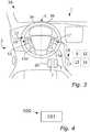
vehicle 50 illustrated inFig. 3 comprises avehicle compartment 3, asteering wheel 5 and at least onepedal 7. - The
vehicle system 1 comprises acontrol arrangement 9 which is configured to control which different driving modes a vehicle operator should be able or allowed to enable and disable. Thecontrol arrangement 9 is arranged to control which actions the vehicle operator has to perform in order to initiate such a transition and possibly also to allow which of the transitions that should be available for the vehicle operator. - The
control arrangement 9 can comprise or be connected to aprocessing unit 12 and/or to adrive arrangement 13 of thehost vehicle 50. In some embodiments the one ormore processing units 12 are used for processing in several different vehicle systems. Someprocessing units 12 may be dedicated to a specific processing task. In some embodiments thehost vehicle 50 and/or thecontrol arrangement 9 may comprise a large number of processing units 12.Thehost vehicle 50 can be controlled to be driven semi-autonomously or fully autonomously by thedrive arrangement 13. - In the autonomous driving mode AD, the
drive arrangement 13 allows thehost vehicle 50 to be driven autonomously along a route or a road. Thedrive arrangement 13 normally comprises an electrical/mechanical control system, arranged to control steering and velocity of thehost vehicle 50 at least partly based on information received from vehicle sensors. The sensors can e.g. be one or more camera sensors, one or more radar sensors and/or one or more lidar-sensors. A camera sensor may be e.g. a front-, side- or rear facing digital camera equipped with or connected to one or more processors with object recognition logics. Hereby surrounding objects, such as road lanes, other vehicles, traffic signs, pedestrians, animals, different obstacles etc. may be detected and in some cases, identified/classified. Radar sensors include transmitters that emit signals that bounce back from objects around the host vehicle, and receivers that receive the returned signals. The radar sensors may include e.g. ultra wide band radars, narrow band radars and/or multi node radars. Lidar-sensors may measure distances to objects through illuminating the objects with a laser and analyzing the reflected light. Other types of sensors used to monitor the vehicle surrounding may be e.g. ultrasonic sensors and/or infrared sensors. Thehost vehicle 50 can also comprise communication equipment such that thehost vehicle 50 is able to send and receive various kinds of information. - The
drive arrangement 13 is connected to a vehicle steering system, such that thedrive arrangement 13, directly or indirectly, can control a direction of at least some of the wheels of thehost vehicle 50. Hereby e.g. a yaw rate of thehost vehicle 50 can be adjusted, such that the driving direction of thehost vehicle 50 is adjusted in accordance with the input from thedrive arrangement 13. Thedrive arrangement 13 is also connected to a host vehicle engine and a host vehicle braking system, such that thedrive arrangement 13, directly or indirectly, can control acceleration and/or deceleration of thehost vehicle 50. Thedrive arrangement 13 can e.g. increase a host vehicle velocity by increasing the engine speed, and decrease the host vehicle velocity by motor-braking or by activation of one or more wheel brakes. Thedrive arrangement 13 may e.g. be connected to an ABS (anti-lock braking system), such that one or more wheel brakes can be activated selectively. - In some embodiments the
host vehicle 50 comprises a navigation system, to which a user can input a preferred host vehicle route. The navigation system can comprise a positioning system, which may determine a host vehicle position and heading. The positioning system can determine the host vehicle position and driving direction e.g. via a satellite based global positioning system or via map matching and a compass. - In some embodiments the
drive arrangement 13 comprises, or is connected to, a number of vehicle subsystems. Each such subsystem may provide some automatic- or semi-autonomous drive functions but cannot autonomously control thehost vehicle 50 from a first destination to a second destination without input from a driver. The host vehicle is in a semi-autonomous driving mode SD when the autonomous drive mode is disabled and one or more semi-autonomous systems are activated. Examples of such subsystem are: adaptive cruise control systems, lane departure control systems, collision avoidance systems, traffic sign recognition systems, some communication systems, some navigation systems, ultrasonic sensor systems, infrared camera systems, inertial measuring systems, intelligent transportation systems, safe road train systems, automatic parking systems etc. - To sum up; In the AD-mode the
host vehicle 50 and thedrive arrangement 13 are responsibility for controlling thevehicle 50. In the SD-mode the vehicle operator is relieved from some tasks but he/she has the responsibility for the vehicle control. When thehost vehicle 50 is in the manual driving mode MD the vehicle operator himself/herself is responsible for substantially all driving related aspects of thevehicle 50.
As illustrated inFig. 3 , thevehicle system 1 comprises afirst switch 15 arranged at afirst position 16 at thesteering wheel 5 and asecond switch 17 arranged at asecond position 18 within the vehicle compartment 3.Thesecond position 18 is separate from thefirst position 16. - The
first switch 15 and/or thesecond switch 17 can be arranged e.g. as a push-button or mechanical switch of any kind. A vehicle operator has to actively activate and/or press thefirst switch 15 and/or thesecond switch 17 in order to enable any functions associated with thefirst switch 15 and/or thesecond switch 17. In some embodiment thefirst switch 15 and/or thesecond switch 17 can be arranged as a touch button, sliding touch button or a display icon. - The
vehicle system 1 also comprises afirst determination arrangement 20 for determining if the at least onepedal 7 is depressed. Thefirst determination arrangement 20 can comprise e.g. a sensor or switch of any kind for the determination. For example, a pressure sensor or a electromechanical switch can be used for the determination. - The
control arrangement 9 is configured to allow a transition from an autonomous driving mode AD to a second driving mode only when it is determined that at least onepedal 7 of thevehicle 50 is depressed when both the first switch and the second switch already are in an activated state, i.e. pressed, pulled or similar by the vehicle operator. The second driving mode can be a semi-autonomous driving mode SD or a manual driving mode MD. - In the
Fig. 3 embodiment thefirst switch 15 is arranged at afirst half 5a of a steering wheel circumference and thesecond switch 17 is arranged at asecond half 5b of the steering wheel circumference. In theFig. 3 embodiment thefirst switch 15 and thesecond switch 17 are arranged at afirst side 22 of thesteering wheel 5, facing away from a steering column. In other embodiments thefirst switch 15 and thesecond switch 17 are arranged at a second side of thesteering wheel 5, facing a steering wheel column and thus away from a seated vehicle operator. As illustrated inFig. 3 , thesecond switch 17 can alternatively be arranged at asecond position 18 which is arranged for example at a dashboard or centerstack of the host vehicle. - As illustrated in
Fig. 3 , thefirst switch 15 and/or thesecond switch 17 can also be arranged as lever-switches steering wheel 5. A vehicle operator can then activate the lever switches by pulling or pushing them in any direction. In some embodiments thevehicle system 1 also comprises a switchactivation determination unit 14 which is arranged to determine the amount of time one or more switches are activated by a vehicle operator. The switchactivation determination unit 14 can be connected to the switches, thecontrol arrangement 9 and/or theprocessing unit 12. Fig. 4 illustrates amethod 100 for allowing transition from an autonomous driving mode AD to a second driving mode in a road vehicle having autonomous driving capabilities, and where the vehicle comprises a vehicle compartment, a steering wheel and at least one pedal.- The
method 100 comprises: allowing101, by a control arrangement, the transition when it is determined, by a first determination arrangement, that at least one pedal of the vehicle is depressed when the first switch and the second switch are simultaneously activated. Fig. 5 illustrates a scenario in which the host vehicle is in the autonomous driving mode AD and in which a vehicle operator intends to drive manually instead, i.e. initiate a transition from autonomous driving mode AD to manual driving mode MD. In order to do this he/she need to simultaneously activate thefirst switch 15 and thesecond switch 17 and depress apedal 7. An activated switch or activated/depressed pedal is indicated by the boxes in the timelines ofFig. 5 and 6 . In theFig. 5 embodiment thefirst switch 15 and thesecond switch 17 have to be simultaneously activated for at least a threshold amountT of timet. The time running from the moment both thefirst switch 15 and thesecond switch 17 are activated is denominated x. Thus, only when x≥T and the vehicle operator has depressed apedal 7 the transition from the autonomous driving mode AD to the manual driving mode MD is allowed to occur.- As illustrated, the vehicle operator can activate one of the switches slightly before the other, but they have to be simultaneously activated for at least the threshold amount T of time t and at least one pedal has to be depressed for the transition from the autonomous driving mode AD to manual driving mode MD. Hereby it is ensured that the vehicle operator is aware of the transition.
- In some embodiments the threshold time T is about 0.5 second. In some embodiments the threshold time T is about 1 second. In some embodiments the threshold time T is more than 1 second, such that 1.5, 2, 2.5 or 3 seconds. The vehicle system can be arranged to use any suitable threshold time T.
Fig. 6 illustrates a scenario in which the host vehicle is in the autonomous driving mode AD. The vehicle operator activates thefirst switch 15,thesecond switch 17 and depress thepedal 7, but as illustrated, he/she stops the activation of thefirst switch 15 too early, before and x=T. Hence, the first 15 and second 16 switches are not activated simultaneously long enough, i.e. x<T. Accordingly no transition from autonomous driving mode AD to a semi-autonomous driving mode SD or manual driving mode MD is allowed to occur.- The time the host vehicle is driven autonomously is indicated with an AD-arrow and the time the host vehicle is driven manually is indicated with an MD-arrow in
Fig. 5 and 6 .
Claims (11)
- A vehicle system (1) for allowing transition from an autonomous driving mode (AD) to a second driving mode in a road vehicle (50) having autonomous driving capabilities and comprising a vehicle compartment (3), a steering wheel (5) and at least one pedal (7), whereby the vehicle system (1) comprises:- a control arrangement (9),- a first switch (15) arranged at a first position (16) at the steering wheel (5),- a second switch (17) arranged at a second position (18) within the vehicle compartment (3), the second position (18) being separate from the first position (16) and- a first determination arrangement (20) for determining if the at least one pedal (7) is depressed,and where the control arrangement (9) is configured to allow the transition when it is determined that at least one pedal (7) of the vehicle is depressed when the first switch (15) and the second switch (17) are simultaneously activated.
- The vehicle system (1) according to claim 1wherein the control arrangement (9) comprises a switch activation determination unit (14) and is configured to allow the transition when it is determined that the first switch (15) and the second switch (17) are simultaneously activated for at least a threshold amount (T) of time (t).
- The vehicle system (1) according to claim 1 or 2wherein the second driving mode is a semi-autonomous driving mode (SD).
- The vehicle system according to claim 1 or 2wherein the second driving mode is a manual driving mode (MD).
- The vehicle system (1) according to any one of the preceding claimswherein the first switch (15) is arranged at a first half (5a) of a steering wheel circumference and the second switch (17) is arranged at a second half (5b) of the steering wheel circumference.
- The vehicle system (1) according to claim 5wherein the first switch (15) and the second switch (17) are arranged at a first side (22) of the steering wheel (5), facing away from a steering column.
- The vehicle system (1) according to claim 5wherein the first switch (15) and the second switch (17) are arranged at a second side of the steering wheel (5), facing a steering wheel column.
- The vehicle system (1) according to claim 1wherein the first switch (15) is a lever-switch (15a) arranged at the steering wheel (5).
- The vehicle system (1) according to claim 1wherein both the first switch (15) and the second switch (17) are lever-switches (15a, 17a) arranged at the steering wheel (5).
- A vehicle (50)characterized in that it comprises a vehicle system (1) according to any one of claims 1-9.
- A method (100) for allowing transition from an autonomous driving mode (AD) to a second driving mode in a road vehicle (50) having autonomous driving capabilities and comprising a vehicle compartment (3), a steering wheel (5) and at least one pedal (7), whereby the method (100) comprises:- allowing (101), by a control arrangement, the transition when it is determined, by a first determination arrangement (20), that at least one pedal (7) of the vehicle is depressed when the first switch (15) and the second switch (17) are simultaneously activated.
Priority Applications (3)
| Application Number | Priority Date | Filing Date | Title |
|---|---|---|---|
| EP15166330.9AEP3091411B1 (en) | 2015-05-05 | 2015-05-05 | Vehicle system, vehicle comprising a vehicle system and method for allowing transition from an autonomous driving mode |
| CN201610267202.1ACN106114517B (en) | 2015-05-05 | 2016-04-27 | Vehicle system, vehicle and method allowing transition from autonomous driving mode |
| US15/140,596US10005474B2 (en) | 2015-05-05 | 2016-04-28 | Vehicle system, vehicle comprising a vehicle system and method for allowing transition from an autonomous driving mode |
Applications Claiming Priority (1)
| Application Number | Priority Date | Filing Date | Title |
|---|---|---|---|
| EP15166330.9AEP3091411B1 (en) | 2015-05-05 | 2015-05-05 | Vehicle system, vehicle comprising a vehicle system and method for allowing transition from an autonomous driving mode |
Publications (2)
| Publication Number | Publication Date |
|---|---|
| EP3091411A1 EP3091411A1 (en) | 2016-11-09 |
| EP3091411B1true EP3091411B1 (en) | 2020-02-19 |
Family
ID=53180541
Family Applications (1)
| Application Number | Title | Priority Date | Filing Date |
|---|---|---|---|
| EP15166330.9AActiveEP3091411B1 (en) | 2015-05-05 | 2015-05-05 | Vehicle system, vehicle comprising a vehicle system and method for allowing transition from an autonomous driving mode |
Country Status (3)
| Country | Link |
|---|---|
| US (1) | US10005474B2 (en) |
| EP (1) | EP3091411B1 (en) |
| CN (1) | CN106114517B (en) |
Families Citing this family (14)
| Publication number | Priority date | Publication date | Assignee | Title |
|---|---|---|---|---|
| JP6321532B2 (en)* | 2014-11-28 | 2018-05-09 | 株式会社デンソー | Vehicle travel control device |
| JP6583061B2 (en)* | 2016-03-08 | 2019-10-02 | トヨタ自動車株式会社 | Automatic operation control device |
| US10059346B2 (en)* | 2016-06-07 | 2018-08-28 | Ford Global Technologies, Llc | Driver competency during autonomous handoff |
| US10351147B2 (en)* | 2016-09-20 | 2019-07-16 | Ford Global Technologies, Llc | Autonomous sensing vehicle pedals |
| KR102299496B1 (en)* | 2017-06-16 | 2021-09-08 | 현대자동차주식회사 | Apparatus and method for controlling autonomous driving of vehicle, vehicle system |
| CN108297877B (en)* | 2017-10-10 | 2019-08-13 | 腾讯科技(深圳)有限公司 | Control method for vehicle, system and device |
| KR20190064302A (en)* | 2017-11-30 | 2019-06-10 | 현대자동차주식회사 | Method and apparatus for controlling driving mode of autonomous driving vehicle |
| US10343559B2 (en)* | 2017-12-12 | 2019-07-09 | Pony.ai, Inc. | Interior compartment of an autonomous vehicle |
| EP3579020B1 (en)* | 2018-06-05 | 2021-03-31 | Elmos Semiconductor SE | Method for recognition of an obstacle with the aid of reflected ultrasonic waves |
| JP7135960B2 (en)* | 2019-03-22 | 2022-09-13 | 株式会社デンソー | Operation transfer device |
| US11077863B2 (en)* | 2019-08-14 | 2021-08-03 | Waymo Llc | Secondary disengage alert for autonomous vehicles |
| GB2588697B (en) | 2020-02-07 | 2021-10-20 | Hybrid Vision Ltd | Control system |
| DE102020110714A1 (en)* | 2020-04-20 | 2021-10-21 | Bayerische Motoren Werke Aktiengesellschaft | Changing a configuration of an active safety system of an automated motor vehicle |
| KR20240082415A (en)* | 2022-11-30 | 2024-06-11 | 현대자동차주식회사 | Method for controlling manual drive mode of autonomous driving vehicle with haptic pedal |
Family Cites Families (15)
| Publication number | Priority date | Publication date | Assignee | Title |
|---|---|---|---|---|
| AU2007331292A1 (en)* | 2006-12-11 | 2008-06-19 | Bae Systems Plc | Controlling an autonomous vehicle system |
| US8775023B2 (en)* | 2009-02-15 | 2014-07-08 | Neanode Inc. | Light-based touch controls on a steering wheel and dashboard |
| US8994521B2 (en)* | 2011-06-29 | 2015-03-31 | GM Global Technology Operations LLC | Steering wheels for vehicle control in manual and autonomous driving |
| FR2984254B1 (en)* | 2011-12-16 | 2016-07-01 | Renault Sa | CONTROL OF AUTONOMOUS VEHICLES |
| EP2607142B1 (en)* | 2011-12-21 | 2017-02-22 | Volvo Car Corporation | System for controlling driving modes of a vehicle |
| KR20140043536A (en)* | 2012-09-24 | 2014-04-10 | 현대자동차주식회사 | Driving control right exanging method for autonomous vehicle |
| JP2014084018A (en)* | 2012-10-25 | 2014-05-12 | Fuji Heavy Ind Ltd | Vehicle control device |
| US8825258B2 (en)* | 2012-11-30 | 2014-09-02 | Google Inc. | Engaging and disengaging for autonomous driving |
| US9007199B2 (en)* | 2013-01-29 | 2015-04-14 | Honda Motor Co., Ltd. | Drive mode selector |
| US9376068B2 (en)* | 2013-03-15 | 2016-06-28 | Judco Partnership, Llc | Paddle switch system |
| GB2519146B (en)* | 2013-10-14 | 2018-05-23 | Jaguar Land Rover Ltd | Input device for a vehicle control system |
| US9573583B2 (en)* | 2014-02-27 | 2017-02-21 | Deere & Company | Vehicle speed control |
| US9475487B2 (en)* | 2014-07-25 | 2016-10-25 | Ford Global Technologies, Llc | Temporary engine start or stop using paddle shifter |
| JP2016101895A (en)* | 2014-11-28 | 2016-06-02 | ヤマハ発動機株式会社 | vehicle |
| CN107249955B (en)* | 2014-12-31 | 2020-09-08 | 罗伯特·博世有限公司 | Controlling autonomous driving modes in autonomous vehicles |
- 2015
- 2015-05-05EPEP15166330.9Apatent/EP3091411B1/enactiveActive
- 2016
- 2016-04-27CNCN201610267202.1Apatent/CN106114517B/enactiveActive
- 2016-04-28USUS15/140,596patent/US10005474B2/enactiveActive
Non-Patent Citations (1)
| Title |
|---|
| None* |
Also Published As
| Publication number | Publication date |
|---|---|
| CN106114517B (en) | 2020-03-13 |
| US20160325757A1 (en) | 2016-11-10 |
| EP3091411A1 (en) | 2016-11-09 |
| US10005474B2 (en) | 2018-06-26 |
| CN106114517A (en) | 2016-11-16 |
Similar Documents
| Publication | Publication Date | Title |
|---|---|---|
| EP3091411B1 (en) | Vehicle system, vehicle comprising a vehicle system and method for allowing transition from an autonomous driving mode | |
| US9714036B2 (en) | Autonomous driving device | |
| US9604652B2 (en) | Method for a driver assistance system for autonomous longitudinal and/or lateral control of a vehicle | |
| US10661792B2 (en) | System and method for performing autonomous emergency braking | |
| US10308249B2 (en) | Adaptive cruise control system and vehicle comprising an adaptive cruise control system | |
| CN107472237B (en) | Adaptive cruise control systems and vehicles including adaptive cruise control systems | |
| US10222796B2 (en) | Autonomous driving control apparatus | |
| US20190152525A1 (en) | Lane-Change Assistance System and Lane-Change Assistance Method for the Automated Performance of Multiple Lane Changes | |
| US9463793B2 (en) | Method for transition between driving modes | |
| US20210163000A1 (en) | Method and system for distance control of a subject vehicle | |
| JP2020189543A (en) | Driving control apparatus for vehicle | |
| KR20210083462A (en) | Advanced Driver Assistance System, Vehicle having the same and method for controlling the vehicle | |
| CN112810607B (en) | Vehicle and control method thereof | |
| JP6962864B2 (en) | Vehicle control system | |
| JP2021049891A (en) | Vehicle control device | |
| CN114684132B (en) | Vehicle control device, vehicle control method, and computer readable storage medium | |
| US10836382B2 (en) | System and method for handling exceptional scenarios | |
| KR20200142154A (en) | Driver assistance system and control method for the same | |
| JP2020144782A (en) | Tow vehicle operation support system | |
| JP2017121851A (en) | Traveling control device of vehicle | |
| JP7385409B2 (en) | Driving support device for manual transmission vehicles | |
| JP2020044939A (en) | Vehicle control system | |
| JP2019209889A (en) | Vehicle control system | |
| KR20220145971A (en) | Driver assistance apparatus and method thereof | |
| KR20230000655A (en) | Vehicle and control method thereof |
Legal Events
| Date | Code | Title | Description |
|---|---|---|---|
| PUAI | Public reference made under article 153(3) epc to a published international application that has entered the european phase | Free format text:ORIGINAL CODE: 0009012 | |
| AK | Designated contracting states | Kind code of ref document:A1 Designated state(s):AL AT BE BG CH CY CZ DE DK EE ES FI FR GB GR HR HU IE IS IT LI LT LU LV MC MK MT NL NO PL PT RO RS SE SI SK SM TR | |
| AX | Request for extension of the european patent | Extension state:BA ME | |
| STAA | Information on the status of an ep patent application or granted ep patent | Free format text:STATUS: REQUEST FOR EXAMINATION WAS MADE | |
| 17P | Request for examination filed | Effective date:20170509 | |
| RBV | Designated contracting states (corrected) | Designated state(s):AL AT BE BG CH CY CZ DE DK EE ES FI FR GB GR HR HU IE IS IT LI LT LU LV MC MK MT NL NO PL PT RO RS SE SI SK SM TR | |
| REG | Reference to a national code | Ref country code:DE Ref legal event code:R079 Ref document number:602015047160 Country of ref document:DE Free format text:PREVIOUS MAIN CLASS: G05D0001000000 Ipc:B60W0050000000 | |
| RIC1 | Information provided on ipc code assigned before grant | Ipc:B62D 1/28 20060101ALI20190716BHEP Ipc:B60W 50/00 20060101AFI20190716BHEP Ipc:G05D 1/00 20060101ALI20190716BHEP Ipc:B60W 50/08 20120101ALI20190716BHEP | |
| GRAP | Despatch of communication of intention to grant a patent | Free format text:ORIGINAL CODE: EPIDOSNIGR1 | |
| STAA | Information on the status of an ep patent application or granted ep patent | Free format text:STATUS: GRANT OF PATENT IS INTENDED | |
| INTG | Intention to grant announced | Effective date:20190916 | |
| RIN1 | Information on inventor provided before grant (corrected) | Inventor name:NILSSON, JONAS Inventor name:WESTLUND, MATHIAS | |
| GRAS | Grant fee paid | Free format text:ORIGINAL CODE: EPIDOSNIGR3 | |
| GRAA | (expected) grant | Free format text:ORIGINAL CODE: 0009210 | |
| STAA | Information on the status of an ep patent application or granted ep patent | Free format text:STATUS: THE PATENT HAS BEEN GRANTED | |
| AK | Designated contracting states | Kind code of ref document:B1 Designated state(s):AL AT BE BG CH CY CZ DE DK EE ES FI FR GB GR HR HU IE IS IT LI LT LU LV MC MK MT NL NO PL PT RO RS SE SI SK SM TR | |
| REG | Reference to a national code | Ref country code:CH Ref legal event code:EP | |
| REG | Reference to a national code | Ref country code:DE Ref legal event code:R096 Ref document number:602015047160 Country of ref document:DE | |
| REG | Reference to a national code | Ref country code:AT Ref legal event code:REF Ref document number:1234635 Country of ref document:AT Kind code of ref document:T Effective date:20200315 | |
| REG | Reference to a national code | Ref country code:IE Ref legal event code:FG4D | |
| REG | Reference to a national code | Ref country code:NL Ref legal event code:MP Effective date:20200219 | |
| PG25 | Lapsed in a contracting state [announced via postgrant information from national office to epo] | Ref country code:RS Free format text:LAPSE BECAUSE OF FAILURE TO SUBMIT A TRANSLATION OF THE DESCRIPTION OR TO PAY THE FEE WITHIN THE PRESCRIBED TIME-LIMIT Effective date:20200219 Ref country code:FI Free format text:LAPSE BECAUSE OF FAILURE TO SUBMIT A TRANSLATION OF THE DESCRIPTION OR TO PAY THE FEE WITHIN THE PRESCRIBED TIME-LIMIT Effective date:20200219 Ref country code:NO Free format text:LAPSE BECAUSE OF FAILURE TO SUBMIT A TRANSLATION OF THE DESCRIPTION OR TO PAY THE FEE WITHIN THE PRESCRIBED TIME-LIMIT Effective date:20200519 | |
| REG | Reference to a national code | Ref country code:LT Ref legal event code:MG4D | |
| PG25 | Lapsed in a contracting state [announced via postgrant information from national office to epo] | Ref country code:IS Free format text:LAPSE BECAUSE OF FAILURE TO SUBMIT A TRANSLATION OF THE DESCRIPTION OR TO PAY THE FEE WITHIN THE PRESCRIBED TIME-LIMIT Effective date:20200619 Ref country code:GR Free format text:LAPSE BECAUSE OF FAILURE TO SUBMIT A TRANSLATION OF THE DESCRIPTION OR TO PAY THE FEE WITHIN THE PRESCRIBED TIME-LIMIT Effective date:20200520 Ref country code:BG Free format text:LAPSE BECAUSE OF FAILURE TO SUBMIT A TRANSLATION OF THE DESCRIPTION OR TO PAY THE FEE WITHIN THE PRESCRIBED TIME-LIMIT Effective date:20200519 Ref country code:HR Free format text:LAPSE BECAUSE OF FAILURE TO SUBMIT A TRANSLATION OF THE DESCRIPTION OR TO PAY THE FEE WITHIN THE PRESCRIBED TIME-LIMIT Effective date:20200219 Ref country code:LV Free format text:LAPSE BECAUSE OF FAILURE TO SUBMIT A TRANSLATION OF THE DESCRIPTION OR TO PAY THE FEE WITHIN THE PRESCRIBED TIME-LIMIT Effective date:20200219 Ref country code:SE Free format text:LAPSE BECAUSE OF FAILURE TO SUBMIT A TRANSLATION OF THE DESCRIPTION OR TO PAY THE FEE WITHIN THE PRESCRIBED TIME-LIMIT Effective date:20200219 | |
| PG25 | Lapsed in a contracting state [announced via postgrant information from national office to epo] | Ref country code:NL Free format text:LAPSE BECAUSE OF FAILURE TO SUBMIT A TRANSLATION OF THE DESCRIPTION OR TO PAY THE FEE WITHIN THE PRESCRIBED TIME-LIMIT Effective date:20200219 | |
| PG25 | Lapsed in a contracting state [announced via postgrant information from national office to epo] | Ref country code:DK Free format text:LAPSE BECAUSE OF FAILURE TO SUBMIT A TRANSLATION OF THE DESCRIPTION OR TO PAY THE FEE WITHIN THE PRESCRIBED TIME-LIMIT Effective date:20200219 Ref country code:LT Free format text:LAPSE BECAUSE OF FAILURE TO SUBMIT A TRANSLATION OF THE DESCRIPTION OR TO PAY THE FEE WITHIN THE PRESCRIBED TIME-LIMIT Effective date:20200219 Ref country code:ES Free format text:LAPSE BECAUSE OF FAILURE TO SUBMIT A TRANSLATION OF THE DESCRIPTION OR TO PAY THE FEE WITHIN THE PRESCRIBED TIME-LIMIT Effective date:20200219 Ref country code:SK Free format text:LAPSE BECAUSE OF FAILURE TO SUBMIT A TRANSLATION OF THE DESCRIPTION OR TO PAY THE FEE WITHIN THE PRESCRIBED TIME-LIMIT Effective date:20200219 Ref country code:RO Free format text:LAPSE BECAUSE OF FAILURE TO SUBMIT A TRANSLATION OF THE DESCRIPTION OR TO PAY THE FEE WITHIN THE PRESCRIBED TIME-LIMIT Effective date:20200219 Ref country code:CZ Free format text:LAPSE BECAUSE OF FAILURE TO SUBMIT A TRANSLATION OF THE DESCRIPTION OR TO PAY THE FEE WITHIN THE PRESCRIBED TIME-LIMIT Effective date:20200219 Ref country code:PT Free format text:LAPSE BECAUSE OF FAILURE TO SUBMIT A TRANSLATION OF THE DESCRIPTION OR TO PAY THE FEE WITHIN THE PRESCRIBED TIME-LIMIT Effective date:20200712 Ref country code:SM Free format text:LAPSE BECAUSE OF FAILURE TO SUBMIT A TRANSLATION OF THE DESCRIPTION OR TO PAY THE FEE WITHIN THE PRESCRIBED TIME-LIMIT Effective date:20200219 Ref country code:EE Free format text:LAPSE BECAUSE OF FAILURE TO SUBMIT A TRANSLATION OF THE DESCRIPTION OR TO PAY THE FEE WITHIN THE PRESCRIBED TIME-LIMIT Effective date:20200219 | |
| REG | Reference to a national code | Ref country code:AT Ref legal event code:MK05 Ref document number:1234635 Country of ref document:AT Kind code of ref document:T Effective date:20200219 | |
| REG | Reference to a national code | Ref country code:DE Ref legal event code:R097 Ref document number:602015047160 Country of ref document:DE | |
| PLBE | No opposition filed within time limit | Free format text:ORIGINAL CODE: 0009261 | |
| STAA | Information on the status of an ep patent application or granted ep patent | Free format text:STATUS: NO OPPOSITION FILED WITHIN TIME LIMIT | |
| 26N | No opposition filed | Effective date:20201120 | |
| PG25 | Lapsed in a contracting state [announced via postgrant information from national office to epo] | Ref country code:LI Free format text:LAPSE BECAUSE OF NON-PAYMENT OF DUE FEES Effective date:20200531 Ref country code:MC Free format text:LAPSE BECAUSE OF FAILURE TO SUBMIT A TRANSLATION OF THE DESCRIPTION OR TO PAY THE FEE WITHIN THE PRESCRIBED TIME-LIMIT Effective date:20200219 Ref country code:AT Free format text:LAPSE BECAUSE OF FAILURE TO SUBMIT A TRANSLATION OF THE DESCRIPTION OR TO PAY THE FEE WITHIN THE PRESCRIBED TIME-LIMIT Effective date:20200219 Ref country code:CH Free format text:LAPSE BECAUSE OF NON-PAYMENT OF DUE FEES Effective date:20200531 | |
| PG25 | Lapsed in a contracting state [announced via postgrant information from national office to epo] | Ref country code:PL Free format text:LAPSE BECAUSE OF FAILURE TO SUBMIT A TRANSLATION OF THE DESCRIPTION OR TO PAY THE FEE WITHIN THE PRESCRIBED TIME-LIMIT Effective date:20200219 Ref country code:SI Free format text:LAPSE BECAUSE OF FAILURE TO SUBMIT A TRANSLATION OF THE DESCRIPTION OR TO PAY THE FEE WITHIN THE PRESCRIBED TIME-LIMIT Effective date:20200219 | |
| REG | Reference to a national code | Ref country code:BE Ref legal event code:MM Effective date:20200531 | |
| GBPC | Gb: european patent ceased through non-payment of renewal fee | Effective date:20200519 | |
| PG25 | Lapsed in a contracting state [announced via postgrant information from national office to epo] | Ref country code:LU Free format text:LAPSE BECAUSE OF NON-PAYMENT OF DUE FEES Effective date:20200505 | |
| PG25 | Lapsed in a contracting state [announced via postgrant information from national office to epo] | Ref country code:GB Free format text:LAPSE BECAUSE OF NON-PAYMENT OF DUE FEES Effective date:20200519 Ref country code:IE Free format text:LAPSE BECAUSE OF NON-PAYMENT OF DUE FEES Effective date:20200505 | |
| PG25 | Lapsed in a contracting state [announced via postgrant information from national office to epo] | Ref country code:BE Free format text:LAPSE BECAUSE OF NON-PAYMENT OF DUE FEES Effective date:20200531 | |
| PG25 | Lapsed in a contracting state [announced via postgrant information from national office to epo] | Ref country code:TR Free format text:LAPSE BECAUSE OF FAILURE TO SUBMIT A TRANSLATION OF THE DESCRIPTION OR TO PAY THE FEE WITHIN THE PRESCRIBED TIME-LIMIT Effective date:20200219 Ref country code:MT Free format text:LAPSE BECAUSE OF FAILURE TO SUBMIT A TRANSLATION OF THE DESCRIPTION OR TO PAY THE FEE WITHIN THE PRESCRIBED TIME-LIMIT Effective date:20200219 Ref country code:CY Free format text:LAPSE BECAUSE OF FAILURE TO SUBMIT A TRANSLATION OF THE DESCRIPTION OR TO PAY THE FEE WITHIN THE PRESCRIBED TIME-LIMIT Effective date:20200219 | |
| PG25 | Lapsed in a contracting state [announced via postgrant information from national office to epo] | Ref country code:MK Free format text:LAPSE BECAUSE OF FAILURE TO SUBMIT A TRANSLATION OF THE DESCRIPTION OR TO PAY THE FEE WITHIN THE PRESCRIBED TIME-LIMIT Effective date:20200219 Ref country code:AL Free format text:LAPSE BECAUSE OF FAILURE TO SUBMIT A TRANSLATION OF THE DESCRIPTION OR TO PAY THE FEE WITHIN THE PRESCRIBED TIME-LIMIT Effective date:20200219 | |
| REG | Reference to a national code | Ref country code:DE Ref legal event code:R081 Ref document number:602015047160 Country of ref document:DE Owner name:POLESTAR PERFORMANCE AB, SE Free format text:FORMER OWNER: VOLVO CAR CORPORATION, GOETEBORG, SE | |
| PGFP | Annual fee paid to national office [announced via postgrant information from national office to epo] | Ref country code:FR Payment date:20250318 Year of fee payment:11 | |
| PGFP | Annual fee paid to national office [announced via postgrant information from national office to epo] | Ref country code:DE Payment date:20250415 Year of fee payment:11 | |
| PGFP | Annual fee paid to national office [announced via postgrant information from national office to epo] | Ref country code:IT Payment date:20250416 Year of fee payment:11 | |
| REG | Reference to a national code | Ref country code:DE Ref legal event code:R082 Ref document number:602015047160 Country of ref document:DE |