EP3090269B1 - System for condition monitoring of electric machine, mobile phone and method thereof - Google Patents
System for condition monitoring of electric machine, mobile phone and method thereofDownload PDFInfo
- Publication number
- EP3090269B1 EP3090269B1EP14726115.0AEP14726115AEP3090269B1EP 3090269 B1EP3090269 B1EP 3090269B1EP 14726115 AEP14726115 AEP 14726115AEP 3090269 B1EP3090269 B1EP 3090269B1
- Authority
- EP
- European Patent Office
- Prior art keywords
- magnetic field
- electric machine
- point
- field intensity
- flux leakage
- Prior art date
- Legal status (The legal status is an assumption and is not a legal conclusion. Google has not performed a legal analysis and makes no representation as to the accuracy of the status listed.)
- Active
Links
Images


Classifications
- G—PHYSICS
- G01—MEASURING; TESTING
- G01R—MEASURING ELECTRIC VARIABLES; MEASURING MAGNETIC VARIABLES
- G01R31/00—Arrangements for testing electric properties; Arrangements for locating electric faults; Arrangements for electrical testing characterised by what is being tested not provided for elsewhere
- G01R31/34—Testing dynamo-electric machines
- G01R31/343—Testing dynamo-electric machines in operation
- G—PHYSICS
- G01—MEASURING; TESTING
- G01R—MEASURING ELECTRIC VARIABLES; MEASURING MAGNETIC VARIABLES
- G01R29/00—Arrangements for measuring or indicating electric quantities not covered by groups G01R19/00 - G01R27/00
- G01R29/08—Measuring electromagnetic field characteristics
- G01R29/0807—Measuring electromagnetic field characteristics characterised by the application
- G01R29/0814—Field measurements related to measuring influence on or from apparatus, components or humans, e.g. in ESD, EMI, EMC, EMP testing, measuring radiation leakage; detecting presence of micro- or radiowave emitters; dosimetry; testing shielding; measurements related to lightning
- G—PHYSICS
- G01—MEASURING; TESTING
- G01R—MEASURING ELECTRIC VARIABLES; MEASURING MAGNETIC VARIABLES
- G01R33/00—Arrangements or instruments for measuring magnetic variables
- G01R33/02—Measuring direction or magnitude of magnetic fields or magnetic flux
- G01R33/04—Measuring direction or magnitude of magnetic fields or magnetic flux using the flux-gate principle
- G—PHYSICS
- G01—MEASURING; TESTING
- G01R—MEASURING ELECTRIC VARIABLES; MEASURING MAGNETIC VARIABLES
- G01R33/00—Arrangements or instruments for measuring magnetic variables
- G01R33/02—Measuring direction or magnitude of magnetic fields or magnetic flux
- G01R33/10—Plotting field distribution ; Measuring field distribution
Definitions
- the inventionrelates to the field of condition monitoring of electric machine.
- the systemincludes a portable unit, being adapted for free movement around said electric machine; a magnetic field sensor, being adapted for measuring magnetic field intensity at at least one of a plurality points of a path of said free movement; a processing unit, being adapted for receiving at least one corresponding magnetic field intensity signal from said magnetic field sensor, comparing at least one magnetic field intensity value to at least one corresponding expected value, and determining, based on the comparison, if a fault is present in the electric machine; wherein: said magnetic field sensor and said processing unit are integrated into said portable unit.
- a first point of said plurality points of said path of said free movementis located in area where an axial magnetic flux leakage is present around said electric machine.
- a second point of said plurality points of said path of said free movementis located in area where a radial magnetic flux leakage is present around said electric machine.
- Said portable unitis adapted to move to said first point.
- Said magnetic field sensoris adapted to measure the magnetic field intensity for said axial magnetic flux leakage present at the first point.
- Said portable unitis adapted to move to said second point.
- Said magnetic field sensoris adapted to measure the magnetic field intensity for said radial magnetic flux leakage present at the second point.
- Said processing unitis adapted for comparing said magnetic field intensity signals for said axial magnetic flux leakage and said radial magnetic flux leakage and determining a type of said fault.
- the methodincludes steps of moving said portable unit to at least one point of a plurality points of a path of said free movement around said electric machine; measuring at least one magnetic field intensity at said at least one of a plurality points of a path of said free movement; and comparing at least one magnetic field intensity value to at least one corresponding expected value, and determining, based on the comparison, if a fault is present in the electric machine.
- a first point of said plurality points of said path of said free movementis located in area where an axial magnetic flux leakage is present around said electric machine.
- a second point of said plurality points of said path of said free movementis located in area where a radial magnetic flux leakage is present around said electric machine. Said portable unit is moved to said first point.
- the magnetic field intensity for said axial magnetic flux leakage present at the first pointis measured.
- Said portable unitis moved to said second point.
- the magnetic field intensity for said radial magnetic flux leakage present at the second pointis measured.
- Said magnetic field intensity signals for said axial magnetic flux leakage and said radial magnetic flux leakageare compared, and a type of said fault is determined.
- the operatorcan hold the portable unit next to the electric machine where conventional magnetic field sensor cannot be installed and where rotor magnetic field leakage is present, either axial or radial.
- the magnetic field leakagecan be measured at a position where installation of magnetic field sensor on the electric machine is restricted due to mechanical or electrical limitation. Besides, it makes the result more accurate by condition monitoring electric machine's magnetic field leakage directly and determining the electric machine's condition accordingly.
- By measuring magnetic field instead of current or vibrationnot only whole analysis can be performed just with the condition monitoring system but by measuring magnetic field the root of the problem is measured directly.
- the first point of said plurality points of said path of said free movementis located in area where an axial magnetic flux leakage is present around said electric machine; said portable unit is adapted to move to said first point; and said magnetic field sensor is adapted to measure the magnetic field intensity for said axial magnetic flux leakage present at the first point.
- a second point of said plurality points of said path of said free movementis located in area where a radial magnetic flux leakage is present around said electric machine; said portable unit is adapted to move to said second point; and said magnetic field sensor is adapted to measure the magnetic field intensity for said radial magnetic flux leakage present at the second point; said processing unit is adapted for comparing said magnetic field intensity signals for said axial magnetic flux leakage and said radial magnetic flux leakage and determining a type of said fault.
- FIG. 1is a block diagram of a system for a system for condition monitoring an electric machine.
- the system according to figure 1is designated with 1 in its entirety.
- the system 1includes a portable unit 10, a magnetic field sensor 11 and a processing unit 12.
- the magnetic field sensor 11 and the processing unit 12are integrated into the portable unit 10.
- the portable unit 10is movable with freedom with respect to the electric machine, for example in linear movement, in circular movement, in forward and backward movement, and so on.
- the portable unit 10can be any device, such as a mobile phone and other electronics devices; for example, processing unit and magnetic field sensor are embedded in the contemporary mobile phone to distinguish healthy machine from the one with broken rotor bar or rotor misalignment, by that no additional hardware except mobile phone is required; contemporary mobile phones such as iphone (3, 4 and 5) or Samsung Galaxy got embedded magnetic field sensor which can measure magnetic field with resolution of 0.1 ⁇ T, range 2k ⁇ T and sampling frequency of 120 Hz; those parameters are slightly changing on different mobile phone models. By using mobile phone for performing flux measurements no other additional sensors, data collectors or data processing tool is required, and all data acquisition and processing can be done on mobile phone.
- processing unit and magnetic field sensorare embedded in the contemporary mobile phone to distinguish healthy machine from the one with broken rotor bar or rotor misalignment, by that no additional hardware except mobile phone is required
- contemporary mobile phonessuch as iphone (3, 4 and 5) or Samsung Galaxy got embedded magnetic field sensor which can measure magnetic field with resolution of 0.1 ⁇ T, range 2k ⁇ T and sampling frequency of 120
- the presence of broken rotor bar or end ringcauses an unbalance to the rotor magnetic flux, as the current cannot flow through the broken or cracked bar/end-ring.
- the unbalanced rotor fluxcan be considered as the combination of positive- and negative-sequence rotor flux, rotating at slip frequency in the opposite directions. This results in modulation of current which can be visible in spectrum as a twice slip sidebands around line frequency.
- the current sidebands around the fundamentalmay exist even when the electric machine is healthy. This could be due to uneven rotor bar resistance because of the die-casting process, rotor asymmetry, external load oscillations etc.
- the integrated magnetic field sensor 11is utilized to measure the magnetic flux leakage of the rotor in case of broken rotor bar or rotor misalignment.
- the magnetic field sensor 11 integrated thereincan measure a magnetic field intensity at at least one of a plurality points of a path of the portable unit 10's free movement, and the skilled person should understand that any path consists of a multiple of points linking together.
- the processing unit 12can receive at least one corresponding magnetic field intensity signal from the magnetic sensor 11, compare at least one magnetic field intensity value to at least one corresponding expected value, and determining, based on the comparison, if a fault is present in the electric machine. This will be described in detail hereafter in examples with illustration of figures.
- the operatorcan hold the portable unit next to the electric machine where conventional magnetic field sensor cannot be installed and where rotor magnetic field leakage is present, either axial or radial.
- the magnetic field leakagecan be measured at a position where installation of magnetic field sensor on the electric machine is restricted due to mechanical or electrical limitation.
- condition monitoring electric machine's magnetic field leakage directlymakes the result more accurate by condition monitoring electric machine's magnetic field leakage directly and determining the electric machine's condition accordingly.
- By measuring magnetic field instead of current or vibrationnot only whole analysis can be performed just with the condition monitoring system but by measuring magnetic field the root of the problem is measured directly.
- Figure 2shows a section view of the magnetic field around an electric machine.
- the magnetic field around the electric machinecan be categorized in two cases, radial field and axial field.
- the axial fieldis in a plan which includes the electric machine axis; it is generated by currents in the stator end windings or rotor cage end ring.
- the radial fieldis located in a plane perpendicular to the electrical axis, it is an image of the air-gap flux density which is attenuated by the stator magnetic circuit (package of laminations) and by the external machine frame.
- the both fieldscan be measured separately by a convenient location of the magnetic field sensor 11 integrated in the portable unit 10.
- Figure 3illustrates a path in which the portable unit according to an embodiment of present invention moves with respective to the electric machine.
- the path 30consists of a multiple of points linking together.
- a first point 31 of the multiple of points of the pathis located in the area where an axial magnetic flux leakage is present around the electric machine
- a second point 32 of the multiple points of the path ofis located in area where a radial magnetic flux leakage is present around the electric machine.
- the portable unit 10can move to the first point 31 or the second point 32 from another point along the path 30, or can move between the first point 31 and the second point 32 along the path 30.
- first point 31 and the second point 32are only for example indicating locations in the areas of an axial magnetic flux leakage and a radial magnetic flux leakage, and the path 30 is for example of the possible route of the portable unit.
- the skilled personshould understand that there is some area of the electric machine on which it is difficult to install the magnetic field sensor, for example in the space X between the end of the rotor and the stator, or where it is difficult to install the magnetic field sensor on the output end of the rotor where the output end of the rotor is mechanically linked to a shaft. With the system according to an embodiment of present invention, it is easier to move the portable unit into such place and measure the rotor magnetic field leakage therein.
- the magnetic field sensor 11 integrated in the portable unit 10can measure the axial magnetic field intensity for axial magnetic flux leakage at the first point 31 or measure the radial magnetic field intensity for radial magnetic flux leakage at the second point 32.
- the processing unit 12 integrated in the portable unit 10can receive the magnetic field intensity signal representing the axial magnetic field leakage at the first point 31 from the magnetic field sensor 11 integrated in the portable unit 10, and/or receive the magnetic field intensity signal representing the radial magnetic field leakage at the first point 32 from the magnetic field sensor 11 integrated in the portable unit 10, and can compare the received magnetic field intensity value to expected value and determine based on the comparison if a fault is present in the electric machine.
- the process of comparison and determination by the processing unit 12will be described in example with figures hereafter.
- f bs * f line
- f bfrequency related to broken rotor bar
- f linepower supply frequency
- sslip
- Figures 4Ashows the spectrum of axial magnetic field leakage of a healthy electric machine, and two cases of electric machine with broken rotor bar. All cases were supplied with 20 Hz and for all cases 20 Hz is dominant frequency visible in magnetic field spectrum. Spectrum was normalized to 1 therefore the units is [pu].
- the spectrum on the rightis a zoom view of the circled portion of the left around the dominant frequency 20 Hz, where the curve representing the axial magnetic field leakage of the healthy electric machine is designated with A, the curves for the two cases of the broken rotor bar are designated with B and C.
- Figure 4Bshows the lower frequency portion of figure 4A .
- the spectrum on the rightis a zoom view of the circled portion of the left.
- respective broken rotor bar frequency fbshould appear in 0.67 Hz.
- curve Ain case of healthy electric machine (curve A), there is no peak which can be easily separate from noise at broken rotor bar frequency fb.
- respective fb frequencyshould be at 1.45 Hz.
- this frequencyis dominant in low frequency range and it is equal to 0.72 of line frequency.
- fb frequencyFor the broken rotor bar motor operating at 50% load respective fb frequency should be at 1.16 Hz. Same as for full load case fb frequency is clearly visible in figure 4B (curve C), this frequency is also dominant in low frequency range and it is around 0.68 of line frequency. What is also worth mentioning is that amplitude of fb frequency is smaller for smaller load which can be explained by the fact that for lower load there is smaller rotor current which is producing smaller magnetic field.
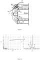
- Figures 5shows the low frequency spectrum of radial magnetic field leakage of a healthy electric machine, and two cases of electric machine with broken rotor bar. Same as in figure 4 all cases were supplied with 20 Hz and for all cases 20 Hz is dominant frequency which was not shown in Figure 5 . Spectrum was normalized to 1 therefore the units is [pu].
- the electric machinewas operated at full load and respective broken rotor bar frequency fb should appear in 0.67 Hz. As it is visible in figure 5 , in case of healthy electric machine (curve A), there is no peak which can be easily separate from noise at broken rotor bar frequency fb.
- respective fb frequencyshould be at 1.45 Hz.
- the system 1can further include an alarm device for generating warning signal in response where said processing unit determined a fault present in the electric machine.
- the methodincludes: in step S1, moving said portable unit to at least one point of a plurality points of a path of said free movement around said electric machine, in step S2, measuring at least one magnetic field intensity at said at least one of a plurality points of a path of said free movement; in step S3, comparing at least one magnetic field intensity value to at least one corresponding expected value, and determining, based on the comparison, if a fault is present in the electric machine.
- the methodfurther includes: in step S4, generating warning signal in response to that fault was determined to be present in the electric machine.
- Step S1may have variants as:
- said magnetic field intensity valueis an amplitude of frequency component of said magnetic field intensity.
Landscapes
- Physics & Mathematics (AREA)
- General Physics & Mathematics (AREA)
- Electromagnetism (AREA)
- Condensed Matter Physics & Semiconductors (AREA)
- Tests Of Circuit Breakers, Generators, And Electric Motors (AREA)
Description
- The invention relates to the field of condition monitoring of electric machine.
- For the purpose of detecting motor fault many diagnostic methods have been developed so far. These methods to identify the induction machine faults may involve several different types of fields of science and technology. The most popular methods are:
- temperature measurements;
- infrared recognition;
- noise and vibration monitoring;
- chemical analysis;
- acoustic noise measurements;
- motor current signature analysis.
- Among them, the most widely uses in industry are vibration monitoring and current signature analysis. All of the above method required sensors for performing measurements and subsequent analysis. By traditional measurements of current or vibration actually not the root of the problem is detected but the consequences of magnetic flux leakage which often can lead to misinterpretation of results. In other words, in terms of the condition monitoring of electric machine, such as electric motor and electric generator, the electric machine's condition inferred from the measurement of the current or vibration of the electric machine is less accurate than that from the measurement of the magnetic field leakage of the rotor.
- Besides, typically to perform condition monitoring of electric machine it is necessary to install sensors on electric machine and use data collector to measure respective signals. Such approach is expensive. Sensors and data collectors might already be expensive however additional cost is related with installation of sensors on the electric machine if customer does not have his own sensors and data collectors.
- Document
US 2008/0265880 A1 discloses a Hall element that outputs a Hall voltage generated at a first terminal pair or a second terminal pair to first and second output terminals. - It is therefore an objective of the invention to provide a system for condition monitoring electric machine and the method thereof. The system includes a portable unit, being adapted for free movement around said electric machine; a magnetic field sensor, being adapted for measuring magnetic field intensity at at least one of a plurality points of a path of said free movement; a processing unit, being adapted for receiving at least one corresponding magnetic field intensity signal from said magnetic field sensor, comparing at least one magnetic field intensity value to at least one corresponding expected value, and determining, based on the comparison, if a fault is present in the electric machine; wherein: said magnetic field sensor and said processing unit are integrated into said portable unit.
- A first point of said plurality points of said path of said free movement is located in area where an axial magnetic flux leakage is present around said electric machine. A second point of said plurality points of said path of said free movement is located in area where a radial magnetic flux leakage is present around said electric machine. Said portable unit is adapted to move to said first point. Said magnetic field sensor is adapted to measure the magnetic field intensity for said axial magnetic flux leakage present at the first point. Said portable unit is adapted to move to said second point. Said magnetic field sensor is adapted to measure the magnetic field intensity for said radial magnetic flux leakage present at the second point. Said processing unit is adapted for comparing said magnetic field intensity signals for said axial magnetic flux leakage and said radial magnetic flux leakage and determining a type of said fault.
- And the method includes steps of moving said portable unit to at least one point of a plurality points of a path of said free movement around said electric machine; measuring at least one magnetic field intensity at said at least one of a plurality points of a path of said free movement; and comparing at least one magnetic field intensity value to at least one corresponding expected value, and determining, based on the comparison, if a fault is present in the electric machine. In the method, a first point of said plurality points of said path of said free movement is located in area where an axial magnetic flux leakage is present around said electric machine. A second point of said plurality points of said path of said free movement is located in area where a radial magnetic flux leakage is present around said electric machine. Said portable unit is moved to said first point. The magnetic field intensity for said axial magnetic flux leakage present at the first point is measured. Said portable unit is moved to said second point. The magnetic field intensity for said radial magnetic flux leakage present at the second point is measured. Said magnetic field intensity signals for said axial magnetic flux leakage and said radial magnetic flux leakage are compared, and a type of said fault is determined.
- By having the system above and the method thereof, to perform condition monitoring of electric machine, the operator can hold the portable unit next to the electric machine where conventional magnetic field sensor cannot be installed and where rotor magnetic field leakage is present, either axial or radial. The magnetic field leakage can be measured at a position where installation of magnetic field sensor on the electric machine is restricted due to mechanical or electrical limitation. Besides, it makes the result more accurate by condition monitoring electric machine's magnetic field leakage directly and determining the electric machine's condition accordingly. By measuring magnetic field instead of current or vibration not only whole analysis can be performed just with the condition monitoring system but by measuring magnetic field the root of the problem is measured directly.
- It is another objective of the invention to provide a mobile phone which includes the system for condition monitoring electric machine and using method thereof. By reusing the mobile phone as the condition monitoring system, no additional cost will incur for purchasing a magnetic field sensor and processing unit.
- It is another objective of the invention to provide an alarm device for generating a warning signal in response where said processing unit determined a fault present in the electric machine.
- According to the invention, the first point of said plurality points of said path of said free movement is located in area where an axial magnetic flux leakage is present around said electric machine; said portable unit is adapted to move to said first point; and said magnetic field sensor is adapted to measure the magnetic field intensity for said axial magnetic flux leakage present at the first point. Thus, it is easier to move the portable unit into a place where it is hard to mount the sensor and measure the rotor magnetic field leakage therein.
- Further according to the the invention, a second point of said plurality points of said path of said free movement is located in area where a radial magnetic flux leakage is present around said electric machine; said portable unit is adapted to move to said second point; and said magnetic field sensor is adapted to measure the magnetic field intensity for said radial magnetic flux leakage present at the second point; said processing unit is adapted for comparing said magnetic field intensity signals for said axial magnetic flux leakage and said radial magnetic flux leakage and determining a type of said fault.
- Thus, it is easier to move the portable unit into a place where it is hard to mount the sensor and measure the rotor magnetic field leakage therein.
- The subject matter of the invention will be explained in more detail in the following text with reference to preferred exemplary embodiments which are illustrated in the drawings, in which:
Figure 1 is a block diagram of a system for a system for condition monitoring an electric machine;Figure 2 shows a section view of the magnetic field around an electric machine;Figure 3 illustrates a path in which the portable unit according to an embodiment of present invention moves with respective to the electric machine;Figures 4A shows the spectrum of axial magnetic field leakage of a healthy electric machine;Figure 4B shows the lower frequency portion offigure 4A ; andFigures 5 shows the low frequency spectrum of radial magnetic field leakage of a healthy electric machine, and two cases of electric machine with broken rotor bar.- The reference symbols used in the drawings, and their meanings, are listed in summary form in the list of reference symbols. In principle, identical parts are provided with the same reference symbols in the figures.
Figure 1 is a block diagram of a system for a system for condition monitoring an electric machine. The system according tofigure 1 is designated with 1 in its entirety. As shown infigure 1 , thesystem 1 includes aportable unit 10, amagnetic field sensor 11 and aprocessing unit 12. Themagnetic field sensor 11 and theprocessing unit 12 are integrated into theportable unit 10. Theportable unit 10 is movable with freedom with respect to the electric machine, for example in linear movement, in circular movement, in forward and backward movement, and so on. Theportable unit 10 can be any device, such as a mobile phone and other electronics devices; for example, processing unit and magnetic field sensor are embedded in the contemporary mobile phone to distinguish healthy machine from the one with broken rotor bar or rotor misalignment, by that no additional hardware except mobile phone is required; contemporary mobile phones such as iphone (3, 4 and 5) or Samsung Galaxy got embedded magnetic field sensor which can measure magnetic field with resolution of 0.1µT, range 2kµT and sampling frequency of 120 Hz; those parameters are slightly changing on different mobile phone models. By using mobile phone for performing flux measurements no other additional sensors, data collectors or data processing tool is required, and all data acquisition and processing can be done on mobile phone. The presence of broken rotor bar or end ring causes an unbalance to the rotor magnetic flux, as the current cannot flow through the broken or cracked bar/end-ring. The unbalanced rotor flux can be considered as the combination of positive- and negative-sequence rotor flux, rotating at slip frequency in the opposite directions. This results in modulation of current which can be visible in spectrum as a twice slip sidebands around line frequency. However, in practice, the current sidebands around the fundamental may exist even when the electric machine is healthy. This could be due to uneven rotor bar resistance because of the die-casting process, rotor asymmetry, external load oscillations etc. According to an embodiment of present invention, the integratedmagnetic field sensor 11 is utilized to measure the magnetic flux leakage of the rotor in case of broken rotor bar or rotor misalignment. When theportable unit 10 moves around the electric machine, themagnetic field sensor 11 integrated therein can measure a magnetic field intensity at at least one of a plurality points of a path of theportable unit 10's free movement, and the skilled person should understand that any path consists of a multiple of points linking together. Theprocessing unit 12 can receive at least one corresponding magnetic field intensity signal from themagnetic sensor 11, compare at least one magnetic field intensity value to at least one corresponding expected value, and determining, based on the comparison, if a fault is present in the electric machine. This will be described in detail hereafter in examples with illustration of figures.- By having the system above, to perform condition monitoring of electric machine, the operator can hold the portable unit next to the electric machine where conventional magnetic field sensor cannot be installed and where rotor magnetic field leakage is present, either axial or radial. The magnetic field leakage can be measured at a position where installation of magnetic field sensor on the electric machine is restricted due to mechanical or electrical limitation.
- Besides, it makes the result more accurate by condition monitoring electric machine's magnetic field leakage directly and determining the electric machine's condition accordingly. By measuring magnetic field instead of current or vibration not only whole analysis can be performed just with the condition monitoring system but by measuring magnetic field the root of the problem is measured directly.
- Finally, by reusing the mobile phone as the condition monitoring system, no additional cost will incur for purchasing a magnetic field sensor and processing unit.
Figure 2 shows a section view of the magnetic field around an electric machine. As shown infigure 2 , the magnetic field around the electric machine can be categorized in two cases, radial field and axial field. The axial field is in a plan which includes the electric machine axis; it is generated by currents in the stator end windings or rotor cage end ring. The radial field is located in a plane perpendicular to the electrical axis, it is an image of the air-gap flux density which is attenuated by the stator magnetic circuit (package of laminations) and by the external machine frame. The both fields can be measured separately by a convenient location of themagnetic field sensor 11 integrated in theportable unit 10. Since broken rotor bars of the electric machine are causing axial magnetic flux leakage it makes sense to make the measurements of magnetic axial field intensity. In addition, since rotor misalignment of the electric machine is causing radial magnetic flux leakage it makes sense to make the measurements of magnetic radial field intensity.Figure 3 illustrates a path in which the portable unit according to an embodiment of present invention moves with respective to the electric machine. As shown infigure 3 , thepath 30 consists of a multiple of points linking together. For example, afirst point 31 of the multiple of points of the path is located in the area where an axial magnetic flux leakage is present around the electric machine, asecond point 32 of the multiple points of the path of is located in area where a radial magnetic flux leakage is present around the electric machine. Theportable unit 10 can move to thefirst point 31 or thesecond point 32 from another point along thepath 30, or can move between thefirst point 31 and thesecond point 32 along thepath 30. The skilled person should understand that thefirst point 31 and thesecond point 32 are only for example indicating locations in the areas of an axial magnetic flux leakage and a radial magnetic flux leakage, and thepath 30 is for example of the possible route of the portable unit. The skilled person should understand that there is some area of the electric machine on which it is difficult to install the magnetic field sensor, for example in the space X between the end of the rotor and the stator, or where it is difficult to install the magnetic field sensor on the output end of the rotor where the output end of the rotor is mechanically linked to a shaft. With the system according to an embodiment of present invention, it is easier to move the portable unit into such place and measure the rotor magnetic field leakage therein. With the various locations of theportable unit 10, for example at thefirst point 31 or at thesecond point 32, themagnetic field sensor 11 integrated in theportable unit 10 can measure the axial magnetic field intensity for axial magnetic flux leakage at thefirst point 31 or measure the radial magnetic field intensity for radial magnetic flux leakage at thesecond point 32. Theprocessing unit 12 integrated in theportable unit 10 can receive the magnetic field intensity signal representing the axial magnetic field leakage at thefirst point 31 from themagnetic field sensor 11 integrated in theportable unit 10, and/or receive the magnetic field intensity signal representing the radial magnetic field leakage at thefirst point 32 from themagnetic field sensor 11 integrated in theportable unit 10, and can compare the received magnetic field intensity value to expected value and determine based on the comparison if a fault is present in the electric machine. The process of comparison and determination by theprocessing unit 12 will be described in example with figures hereafter.- Based on FEM (Finite Element Method) analysis, magnetic flux leakage should be visible in low frequency of magnetic field spectrum as given by equation (1):

Figures 4A shows the spectrum of axial magnetic field leakage of a healthy electric machine, and two cases of electric machine with broken rotor bar. All cases were supplied with 20 Hz and for allcases 20 Hz is dominant frequency visible in magnetic field spectrum. Spectrum was normalized to 1 therefore the units is [pu]. As shown infigure 4A , the spectrum on the right is a zoom view of the circled portion of the left around thedominant frequency 20 Hz, where the curve representing the axial magnetic field leakage of the healthy electric machine is designated with A, the curves for the two cases of the broken rotor bar are designated with B and C.Figure 4B shows the lower frequency portion offigure 4A . As shown infigure 4B , the spectrum on the right is a zoom view of the circled portion of the left. For healthy case the electric machine was operated at full load and respective broken rotor bar frequency fb should appear in 0.67 Hz. As it is visible infigure 4B , in case of healthy electric machine (curve A), there is no peak which can be easily separate from noise at broken rotor bar frequency fb. For the broken rotor bar motor operating at full load respective fb frequency should be at 1.45 Hz. As it is clearly visible infigure 4B this frequency (curve B) is dominant in low frequency range and it is equal to 0.72 of line frequency. For the broken rotor bar motor operating at 50% load respective fb frequency should be at 1.16 Hz. Same as for full load case fb frequency is clearly visible infigure 4B (curve C), this frequency is also dominant in low frequency range and it is around 0.68 of line frequency. What is also worth mentioning is that amplitude of fb frequency is smaller for smaller load which can be explained by the fact that for lower load there is smaller rotor current which is producing smaller magnetic field.Figures 5 shows the low frequency spectrum of radial magnetic field leakage of a healthy electric machine, and two cases of electric machine with broken rotor bar. Same as infigure 4 all cases were supplied with 20 Hz and for allcases 20 Hz is dominant frequency which was not shown inFigure 5 . Spectrum was normalized to 1 therefore the units is [pu]. For healthy case the electric machine was operated at full load and respective broken rotor bar frequency fb should appear in 0.67 Hz. As it is visible infigure 5 , in case of healthy electric machine (curve A), there is no peak which can be easily separate from noise at broken rotor bar frequency fb. For the broken rotor bar motor operating at full load respective fb frequency should be at 1.45 Hz. As it is clearly visible infigure 5 this frequency (curves B) is dominant in low frequency range and it is equal to 0.4 of line frequency. For the broken rotor bar motor operating at 50% load respective fb frequency should be at 1.16 Hz. Same as for full load case fb frequency is clearly visible infigure 5 , this frequency is also dominant in low frequency range and it is around 0.38 of line frequency. What is also worth mentioning is that amplitude of fb frequency is smaller in radial magnetic field than respective amplitude fb frequency in axial magnetic field which confirms broken rotor bar. If amplitude of fb frequency in radial magnetic field is larger than amplitude of fb frequency in axial magnetic field then motor fault type is misalignment not broken rotor bar.- The
system 1 can further include an alarm device for generating warning signal in response where said processing unit determined a fault present in the electric machine. - By using the system as described above, a method for condition monitoring electric machine is describe hereafter. The method includes: in step S1, moving said portable unit to at least one point of a plurality points of a path of said free movement around said electric machine, in step S2, measuring at least one magnetic field intensity at said at least one of a plurality points of a path of said free movement; in step S3, comparing at least one magnetic field intensity value to at least one corresponding expected value, and determining, based on the comparison, if a fault is present in the electric machine.
- Preferably, the method further includes: in step S4, generating warning signal in response to that fault was determined to be present in the electric machine.
- Step S1 may have variants as:
- i. a first point of said plurality points of said path of said free movement is located in area where an axial magnetic flux leakage is present around said electric machine;
- moving said portable unit can move to said first point; and
- measuring the magnetic field intensity for said axial magnetic flux leakage present at the first point.
- ii. a second point of said plurality points of said path of said free movement is located in area where a radial magnetic flux leakage is present around said electric machine;
- moving said portable unit can move to said second point; and
- measuring the magnetic field intensity for said radial magnetic flux leakage present at the second point.
- iii. in combination of variant i,
- a second point of said plurality points of said path of said free movement is located in area where a radial magnetic flux leakage is present around said electric machine;
- moving said portable unit can move to said second point;
- measuring the magnetic field intensity for said radial magnetic flux leakage present at the second point; and
- comparing said magnetic field intensity signals for said axial magnetic flux leakage and said radial magnetic flux leakage and determining a type of said fault.
- Preferably in step S3, said magnetic field intensity value is an amplitude of frequency component of said magnetic field intensity.
- Though the present invention has been described on the basis of some preferred embodiments, those skilled in the art should appreciate that those embodiments should by no way limit the present invention. Any variations and modifications to the embodiments and within the scope ot the claims should be within the apprehension of those with ordinary knowledge and skills in the art.

Claims (7)
- A system (1) for condition monitoring electric machine, including:a portable unit (10), being adapted for free movement around said electric machine;a magnetic field sensor (11), being adapted for measuring magnetic field intensity at at least one of a plurality points of a path (30) of said free movement;a processing unit (12), being adapted for receiving at least one corresponding magnetic field intensity signal from said magnetic field sensor (11), comparing at least one magnetic field intensity value to at least one corresponding expected value, and determining, based on the comparison, if a fault is present in the electric machine;wherein:said magnetic field sensor (11) and said processing unit (12) are integrated into said portable unit (10);a first point (31) of said plurality points of said path (30) of said free movement is located in area where an axial magnetic flux leakage is present around said electric machine;a second point (32) of said plurality points of said path (30) of said free movement is located in area where a radial magnetic flux leakage is present around said electric machine;said portable unit (10) is adapted to move to said first point (31);said magnetic field sensor (11) is adapted to measure the magnetic field intensity for said axial magnetic flux leakage present at the first point (31);said portable unit (10) is adapted to move to said second point (32);said magnetic field sensor (11) is adapted to measure the magnetic field intensity for said radial magnetic flux leakage present at the second point (32); andsaid processing unit (12) is adapted for comparing said magnetic field intensity signals for said axial magnetic flux leakage and said radial magnetic flux leakage and determining a type of said fault.
- The system (1) according to claim 1, including:
an alarm device, being adapted for generating warning signal in response where said processing unit determined a fault present in the electric machine. - The system (1) according to any of the preceding claims, wherein:
said magnetic field intensity value is an amplitude of frequency component of said magnetic field intensity. - A method for condition monitoring electric machine using the system (1) according to any of the preceding claims, including:moving said portable unit (10) to at least one point of a plurality points of a path (30) of said free movement around said electric machine;measuring at least one magnetic field intensity at said at least one of a plurality points of a path (30) of said free movement;comparing at least one magnetic field intensity value to at least one corresponding expected value, and determining, based on the comparison, if a fault is present in the electric machine; whereina first point (31) of said plurality points of said path (30) of said free movement is located in area where an axial magnetic flux leakage is present around said electric machine;a second point (32) of said plurality points of said path of said free movement is located in area where a radial magnetic flux leakage is present around said electric machine;moving said portable unit (10) to said first point;measuring the magnetic field intensity for said axial magnetic flux leakage present at the first point (31);moving said portable unit (10) to said second point (32);measuring the magnetic field intensity for said radial magnetic flux leakage present at the second point (32); andcomparing said magnetic field intensity signals for said axial magnetic flux leakage and said radial magnetic flux leakage and determining a type of said fault.
- The method according to claim 4, including:
generating a warning signal in response to that fault was determined to be present in the electric machine. - The method according to any of claims 4 or 5, wherein:
said magnetic field intensity value is an amplitude of frequency component of said magnetic field intensity. - A mobile phone including the system according to any of claims 1 to 3.
Applications Claiming Priority (2)
| Application Number | Priority Date | Filing Date | Title |
|---|---|---|---|
| CN201310750046 | 2013-12-30 | ||
| PCT/EP2014/059994WO2015101422A1 (en) | 2013-12-30 | 2014-05-15 | System for condition monitoring of electric machine, mobile phone and method thereof |
Publications (3)
| Publication Number | Publication Date |
|---|---|
| EP3090269A1 EP3090269A1 (en) | 2016-11-09 |
| EP3090269B1true EP3090269B1 (en) | 2023-07-12 |
| EP3090269C0 EP3090269C0 (en) | 2023-07-12 |
Family
ID=50792429
Family Applications (1)
| Application Number | Title | Priority Date | Filing Date |
|---|---|---|---|
| EP14726115.0AActiveEP3090269B1 (en) | 2013-12-30 | 2014-05-15 | System for condition monitoring of electric machine, mobile phone and method thereof |
Country Status (6)
| Country | Link |
|---|---|
| US (2) | US10353004B2 (en) |
| EP (1) | EP3090269B1 (en) |
| CN (2) | CN105874344B (en) |
| AU (1) | AU2015260884B2 (en) |
| ES (1) | ES2682951T3 (en) |
| WO (1) | WO2015101422A1 (en) |
Families Citing this family (25)
| Publication number | Priority date | Publication date | Assignee | Title |
|---|---|---|---|---|
| US11747407B2 (en) | 2014-02-03 | 2023-09-05 | Innovaura Corporation | System and method for characterizing defects in electronic items using magnetic field detection |
| US11287484B2 (en) | 2014-02-03 | 2022-03-29 | Innovaura Corporation | Method and apparatus for triage of electronic items using magnetic field detection |
| WO2019232364A1 (en)* | 2018-05-31 | 2019-12-05 | Innovaura Corporation | Method and apparatus for triage of electronic items using magnetic field detection |
| CN106706028B (en)* | 2015-11-13 | 2021-03-02 | Abb技术有限公司 | Method and system for detecting motor state |
| US11209487B2 (en)* | 2016-06-13 | 2021-12-28 | Hitachi, Ltd. | Rotor diagnostic apparatus, rotor diagnostic method, and rotor diagnostic program |
| CN107764316A (en)* | 2016-08-23 | 2018-03-06 | Abb 瑞士有限公司 | For the system for the situation for monitoring multiple motors |
| CN106438325B (en)* | 2016-11-29 | 2018-07-17 | 芜湖美智空调设备有限公司 | Electrical equipment and its compressor condition detection method, server and intelligent terminal |
| WO2018109572A1 (en)* | 2016-12-12 | 2018-06-21 | Abb Schweiz Ag | Method for monitoring a rotating machine and condition monitoring device thereof |
| CN108226777B (en)* | 2016-12-15 | 2020-11-27 | Abb瑞士股份有限公司 | Condition monitoring device and method for monitoring an electric machine |
| DE102017101944A1 (en)* | 2017-02-01 | 2018-08-02 | Wobben Properties Gmbh | Method for determining fault on a generator and generator test system |
| EP3382863B1 (en)* | 2017-03-30 | 2021-08-11 | ABB Schweiz AG | A method for detecting a rotor bar fault |
| US11493379B2 (en)* | 2017-04-26 | 2022-11-08 | Augury Systems Ltd. | Systems and methods for monitoring of mechanical and electrical machines |
| US10353005B2 (en)* | 2017-07-13 | 2019-07-16 | Itt Manufacturing Enterprises Llc | Technique for self learning motor load profile |
| WO2019123078A1 (en)* | 2017-12-19 | 2019-06-27 | Abb Schweiz Ag | Condition monitoring device for monitoring operations of motor |
| US10969435B2 (en)* | 2018-02-12 | 2021-04-06 | Brandon & Clark, Inc. | System and method for induction motor rotor bar surface magnetic field analysis |
| EP3623828A1 (en)* | 2018-09-14 | 2020-03-18 | Hitech & Development Wireless Sweden AB | Machine operation monitoring |
| CN113227926B (en)* | 2018-12-21 | 2024-08-27 | Abb瑞士股份有限公司 | Condition monitoring device and method for monitoring electric motor |
| CN110531259B (en)* | 2019-08-12 | 2020-08-18 | 西安交通大学 | Electrical fault diagnosis method for induction motor based on magnetic leakage signal |
| AU2020395182B9 (en) | 2019-12-03 | 2023-04-27 | Fluid Handling Llc | Operational condition monitoring system |
| DE102020123957A1 (en)* | 2020-09-15 | 2022-03-17 | Bayerische Motoren Werke Aktiengesellschaft | Method for detecting a fault in a rotor of an electric motor and controller |
| CN115389190B (en)* | 2020-09-21 | 2024-07-23 | 成都卓微科技有限公司 | Diagnostic system for equipment operation state |
| DE102021133890A1 (en)* | 2021-12-20 | 2023-06-22 | Danfoss Power Electronics A/S | Commissioning of a drive assisted by a portable device |
| CN114264956B (en)* | 2021-12-23 | 2022-12-06 | 中山东菱威力电器有限公司 | Method for identifying initial state of synchronous motor |
| CN115356668B (en)* | 2022-10-20 | 2023-02-03 | 深圳市好盈科技股份有限公司 | Motor rotor magnetic field distribution process detection method |
| CN119270057B (en)* | 2024-09-20 | 2025-04-11 | 山东海纳智能装备科技股份有限公司 | Permanent magnet motor performance test method and device |
Family Cites Families (27)
| Publication number | Priority date | Publication date | Assignee | Title |
|---|---|---|---|---|
| GB692659A (en)* | 1951-03-14 | 1953-06-10 | Electrical & Auto Products 193 | Improvements relating to electrical testing apparatus |
| US2689331A (en)* | 1951-03-26 | 1954-09-14 | Willford H Boyce | Apparatus for testing electromagnetic fields |
| US3506914A (en)* | 1968-07-01 | 1970-04-14 | Gen Electric | Method and apparatus for detecting rotor flux variations in the air gap of a dynamoelectric machine |
| JPS57196887A (en) | 1981-05-28 | 1982-12-02 | Toyo Electric Mfg Co Ltd | Controller for induction motor |
| GB8428199D0 (en) | 1984-11-08 | 1984-12-19 | Adwel Ltd | Motor monitor signal analysis system |
| RO91569B1 (en) | 1984-12-27 | 1987-05-04 | Institutul De Cercetare Stiintifica Si Inginerie Tehnologica Pentru Electrotehnica | Method and device for measuring the rotor slip frequency of the asynchronous machine with rotor in short circuit connected to the network by static changers with variable frequency and impressed current |
| JPH0763240B2 (en) | 1987-03-30 | 1995-07-05 | 株式会社東芝 | Secondary circuit constant calculator |
| US5049815A (en)* | 1990-04-20 | 1991-09-17 | General Electric Company | Spectral analysis of induction motor current to detect rotor faults with reduced false alarms |
| US5519337A (en) | 1993-11-04 | 1996-05-21 | Martin Marietta Energy Systems, Inc. | Motor monitoring method and apparatus using high frequency current components |
| US5680025A (en)* | 1994-10-07 | 1997-10-21 | Csi Technology, Inc. | Proactive motor monitoring for avoiding premature failures and for fault recognition |
| JPH09304489A (en)* | 1996-05-09 | 1997-11-28 | Matsushita Electric Ind Co Ltd | Method of measuring motor constant of induction motor |
| US6144924A (en)* | 1996-05-20 | 2000-11-07 | Crane Nuclear, Inc. | Motor condition and performance analyzer |
| US5739698A (en)* | 1996-06-20 | 1998-04-14 | Csi Technology, Inc. | Machine fault detection using slot pass frequency flux measurements |
| US6466009B1 (en)* | 2001-06-06 | 2002-10-15 | The United States Of America As Represented By The Secretary Of The Interior | Flexible printed circuit magnetic flux probe |
| US7208971B2 (en)* | 2002-10-15 | 2007-04-24 | General Electric Company | Manual probe carriage system and method of using the same |
| US7081760B2 (en)* | 2004-07-12 | 2006-07-25 | Behrooz Mirafzal | Method of diagnosing a broken bar fault in an induction motor |
| EP1850143A1 (en)* | 2005-02-08 | 2007-10-31 | Rohm Co., Ltd. | Magnetic sensor circuit and portable terminal provided with such magnetic sensor circuit |
| JP5217205B2 (en)* | 2007-03-27 | 2013-06-19 | ソニー株式会社 | motor |
| CN101295040B (en) | 2007-04-27 | 2011-06-29 | 鸿富锦精密工业(深圳)有限公司 | Backlight module and its optical board |
| US20100169030A1 (en)* | 2007-05-24 | 2010-07-01 | Alexander George Parlos | Machine condition assessment through power distribution networks |
| US20090219030A1 (en)* | 2008-02-29 | 2009-09-03 | General Electric Company | Methods and Systems for Detecting Rotor Field Ground Faults In Rotating Machinery |
| US7880473B2 (en)* | 2008-03-31 | 2011-02-01 | General Electric Company | Non-invasive monitoring and diagnosis of electric machines by measuring external flux density |
| WO2010039153A1 (en) | 2008-10-04 | 2010-04-08 | Skf Usa, Inc. | Portable system for immotive multiphasic motive force electrical machine testing |
| US8771078B2 (en) | 2009-06-08 | 2014-07-08 | Cfph, Llc | Amusement device including means for processing electronic data in play of a game of chance |
| US8823412B2 (en)* | 2012-03-06 | 2014-09-02 | Siemens Energy, Inc. | Device and method for inspection of a stator core of an electrical machine |
| CN102914741B (en) | 2012-10-17 | 2015-02-18 | 深圳市航盛电子股份有限公司 | Method and device for measuring parameter of asynchronous motor |
| GB201404226D0 (en)* | 2014-03-11 | 2014-04-23 | Rolls Royce Plc | Fault detection in induction machines |
- 2014
- 2014-05-15WOPCT/EP2014/059994patent/WO2015101422A1/enactiveApplication Filing
- 2014-05-15CNCN201480071979.XApatent/CN105874344B/enactiveActive
- 2014-05-15EPEP14726115.0Apatent/EP3090269B1/enactiveActive
- 2015
- 2015-03-24ESES15714035.1Tpatent/ES2682951T3/enactiveActive
- 2015-03-24USUS15/310,782patent/US10353004B2/enactiveActive
- 2015-03-24CNCN201580025228.9Apatent/CN106537164B/enactiveActive
- 2015-03-24AUAU2015260884Apatent/AU2015260884B2/enactiveActive
- 2016
- 2016-06-29USUS15/196,858patent/US10184986B2/enactiveActive
Also Published As
| Publication number | Publication date |
|---|---|
| CN106537164B (en) | 2019-03-08 |
| EP3090269A1 (en) | 2016-11-09 |
| AU2015260884A1 (en) | 2016-12-01 |
| CN105874344B (en) | 2019-01-04 |
| ES2682951T3 (en) | 2018-09-24 |
| CN106537164A (en) | 2017-03-22 |
| WO2015101422A1 (en) | 2015-07-09 |
| US10184986B2 (en) | 2019-01-22 |
| EP3090269C0 (en) | 2023-07-12 |
| CN105874344A (en) | 2016-08-17 |
| US10353004B2 (en) | 2019-07-16 |
| US20170082692A1 (en) | 2017-03-23 |
| AU2015260884B2 (en) | 2018-01-04 |
| US20160306012A1 (en) | 2016-10-20 |
Similar Documents
| Publication | Publication Date | Title |
|---|---|---|
| EP3090269B1 (en) | System for condition monitoring of electric machine, mobile phone and method thereof | |
| Zhang et al. | Model-based analysis and quantification of bearing faults in induction machines | |
| Zamudio-Ramirez et al. | Magnetic flux analysis for the condition monitoring of electric machines: A review | |
| EP2702374B1 (en) | Method for monitoring demagnetization | |
| Jung et al. | Online diagnosis of induction motors using MCSA | |
| Surya et al. | A simplified frequency-domain detection of stator turn fault in squirrel-cage induction motors using an observer coil technique | |
| EP3143418B1 (en) | Method and system for detecting rotor fault | |
| CN104755947B (en) | Method for the diagnosis of the Mechatronic Systems based on impedance analysis | |
| EP2728367B1 (en) | A method for detecting a fault condition in an electrical machine | |
| EP2919027A1 (en) | Fault detection in induction machines | |
| CN106304846B (en) | Method and system for determining fault status of synchronous machine | |
| EP3306284A1 (en) | A method and apparatus for diagnosing a fault condition in an electric machine | |
| Eftekhari et al. | Review of induction motor testing and monitoring methods for inter-turn stator winding faults | |
| Ehya et al. | Static and dynamic eccentricity fault diagnosis of large salient pole synchronous generators by means of external magnetic field | |
| CN103926508A (en) | Detection system and method used for motor stator winding | |
| WO2013136098A1 (en) | Method for rotor winding damage detection in rotating alternating machines by differential measurement of magnetic field by using two measuring coils | |
| US11959978B2 (en) | Method of detecting a rotor bar fault and a method of estimating an additional operating expenditure due to one or more mechanical anomalies in an electrical machine | |
| EP2933647A1 (en) | A model based diagnostic of induction machine | |
| US20230396133A1 (en) | Method for monitoring the operation of a drive component | |
| KR20100028325A (en) | Method for detecting degradation of motor winding |
Legal Events
| Date | Code | Title | Description |
|---|---|---|---|
| PUAI | Public reference made under article 153(3) epc to a published international application that has entered the european phase | Free format text:ORIGINAL CODE: 0009012 | |
| 17P | Request for examination filed | Effective date:20160729 | |
| AK | Designated contracting states | Kind code of ref document:A1 Designated state(s):AL AT BE BG CH CY CZ DE DK EE ES FI FR GB GR HR HU IE IS IT LI LT LU LV MC MK MT NL NO PL PT RO RS SE SI SK SM TR | |
| AX | Request for extension of the european patent | Extension state:BA ME | |
| DAX | Request for extension of the european patent (deleted) | ||
| STAA | Information on the status of an ep patent application or granted ep patent | Free format text:STATUS: EXAMINATION IS IN PROGRESS | |
| 17Q | First examination report despatched | Effective date:20210604 | |
| REG | Reference to a national code | Ref country code:DE Ref legal event code:R079 Free format text:PREVIOUS MAIN CLASS: G01R0031340000 Ipc:G01R0029080000 Ref country code:DE Ref legal event code:R079 Ref document number:602014087593 Country of ref document:DE Free format text:PREVIOUS MAIN CLASS: G01R0031340000 Ipc:G01R0029080000 | |
| RIC1 | Information provided on ipc code assigned before grant | Ipc:G01R 31/34 20060101ALI20230131BHEP Ipc:G01R 33/10 20060101ALI20230131BHEP Ipc:G01R 29/08 20060101AFI20230131BHEP | |
| GRAP | Despatch of communication of intention to grant a patent | Free format text:ORIGINAL CODE: EPIDOSNIGR1 | |
| STAA | Information on the status of an ep patent application or granted ep patent | Free format text:STATUS: GRANT OF PATENT IS INTENDED | |
| INTG | Intention to grant announced | Effective date:20230316 | |
| GRAS | Grant fee paid | Free format text:ORIGINAL CODE: EPIDOSNIGR3 | |
| GRAA | (expected) grant | Free format text:ORIGINAL CODE: 0009210 | |
| STAA | Information on the status of an ep patent application or granted ep patent | Free format text:STATUS: THE PATENT HAS BEEN GRANTED | |
| RAP3 | Party data changed (applicant data changed or rights of an application transferred) | Owner name:ABB SCHWEIZ AG | |
| AK | Designated contracting states | Kind code of ref document:B1 Designated state(s):AL AT BE BG CH CY CZ DE DK EE ES FI FR GB GR HR HU IE IS IT LI LT LU LV MC MK MT NL NO PL PT RO RS SE SI SK SM TR | |
| REG | Reference to a national code | Ref country code:CH Ref legal event code:EP | |
| REG | Reference to a national code | Ref country code:DE Ref legal event code:R096 Ref document number:602014087593 Country of ref document:DE | |
| REG | Reference to a national code | Ref country code:IE Ref legal event code:FG4D | |
| U01 | Request for unitary effect filed | Effective date:20230801 | |
| U07 | Unitary effect registered | Designated state(s):AT BE BG DE DK EE FI FR IT LT LU LV MT NL PT SE SI Effective date:20230807 | |
| REG | Reference to a national code | Ref country code:LT Ref legal event code:MG9D | |
| PG25 | Lapsed in a contracting state [announced via postgrant information from national office to epo] | Ref country code:GR Free format text:LAPSE BECAUSE OF FAILURE TO SUBMIT A TRANSLATION OF THE DESCRIPTION OR TO PAY THE FEE WITHIN THE PRESCRIBED TIME-LIMIT Effective date:20231013 | |
| PG25 | Lapsed in a contracting state [announced via postgrant information from national office to epo] | Ref country code:ES Free format text:LAPSE BECAUSE OF FAILURE TO SUBMIT A TRANSLATION OF THE DESCRIPTION OR TO PAY THE FEE WITHIN THE PRESCRIBED TIME-LIMIT Effective date:20230712 | |
| PG25 | Lapsed in a contracting state [announced via postgrant information from national office to epo] | Ref country code:IS Free format text:LAPSE BECAUSE OF FAILURE TO SUBMIT A TRANSLATION OF THE DESCRIPTION OR TO PAY THE FEE WITHIN THE PRESCRIBED TIME-LIMIT Effective date:20231112 | |
| PG25 | Lapsed in a contracting state [announced via postgrant information from national office to epo] | Ref country code:RS Free format text:LAPSE BECAUSE OF FAILURE TO SUBMIT A TRANSLATION OF THE DESCRIPTION OR TO PAY THE FEE WITHIN THE PRESCRIBED TIME-LIMIT Effective date:20230712 Ref country code:NO Free format text:LAPSE BECAUSE OF FAILURE TO SUBMIT A TRANSLATION OF THE DESCRIPTION OR TO PAY THE FEE WITHIN THE PRESCRIBED TIME-LIMIT Effective date:20231012 Ref country code:IS Free format text:LAPSE BECAUSE OF FAILURE TO SUBMIT A TRANSLATION OF THE DESCRIPTION OR TO PAY THE FEE WITHIN THE PRESCRIBED TIME-LIMIT Effective date:20231112 Ref country code:HR Free format text:LAPSE BECAUSE OF FAILURE TO SUBMIT A TRANSLATION OF THE DESCRIPTION OR TO PAY THE FEE WITHIN THE PRESCRIBED TIME-LIMIT Effective date:20230712 Ref country code:GR Free format text:LAPSE BECAUSE OF FAILURE TO SUBMIT A TRANSLATION OF THE DESCRIPTION OR TO PAY THE FEE WITHIN THE PRESCRIBED TIME-LIMIT Effective date:20231013 Ref country code:ES Free format text:LAPSE BECAUSE OF FAILURE TO SUBMIT A TRANSLATION OF THE DESCRIPTION OR TO PAY THE FEE WITHIN THE PRESCRIBED TIME-LIMIT Effective date:20230712 | |
| PG25 | Lapsed in a contracting state [announced via postgrant information from national office to epo] | Ref country code:PL Free format text:LAPSE BECAUSE OF FAILURE TO SUBMIT A TRANSLATION OF THE DESCRIPTION OR TO PAY THE FEE WITHIN THE PRESCRIBED TIME-LIMIT Effective date:20230712 | |
| REG | Reference to a national code | Ref country code:DE Ref legal event code:R097 Ref document number:602014087593 Country of ref document:DE | |
| PG25 | Lapsed in a contracting state [announced via postgrant information from national office to epo] | Ref country code:SM Free format text:LAPSE BECAUSE OF FAILURE TO SUBMIT A TRANSLATION OF THE DESCRIPTION OR TO PAY THE FEE WITHIN THE PRESCRIBED TIME-LIMIT Effective date:20230712 Ref country code:RO Free format text:LAPSE BECAUSE OF FAILURE TO SUBMIT A TRANSLATION OF THE DESCRIPTION OR TO PAY THE FEE WITHIN THE PRESCRIBED TIME-LIMIT Effective date:20230712 Ref country code:CZ Free format text:LAPSE BECAUSE OF FAILURE TO SUBMIT A TRANSLATION OF THE DESCRIPTION OR TO PAY THE FEE WITHIN THE PRESCRIBED TIME-LIMIT Effective date:20230712 Ref country code:SK Free format text:LAPSE BECAUSE OF FAILURE TO SUBMIT A TRANSLATION OF THE DESCRIPTION OR TO PAY THE FEE WITHIN THE PRESCRIBED TIME-LIMIT Effective date:20230712 | |
| PLBE | No opposition filed within time limit | Free format text:ORIGINAL CODE: 0009261 | |
| STAA | Information on the status of an ep patent application or granted ep patent | Free format text:STATUS: NO OPPOSITION FILED WITHIN TIME LIMIT | |
| 26N | No opposition filed | Effective date:20240415 | |
| U20 | Renewal fee for the european patent with unitary effect paid | Year of fee payment:11 Effective date:20240527 | |
| REG | Reference to a national code | Ref country code:CH Ref legal event code:PL | |
| PG25 | Lapsed in a contracting state [announced via postgrant information from national office to epo] | Ref country code:MC Free format text:LAPSE BECAUSE OF FAILURE TO SUBMIT A TRANSLATION OF THE DESCRIPTION OR TO PAY THE FEE WITHIN THE PRESCRIBED TIME-LIMIT Effective date:20230712 | |
| GBPC | Gb: european patent ceased through non-payment of renewal fee | Effective date:20240515 | |
| PG25 | Lapsed in a contracting state [announced via postgrant information from national office to epo] | Ref country code:MC Free format text:LAPSE BECAUSE OF FAILURE TO SUBMIT A TRANSLATION OF THE DESCRIPTION OR TO PAY THE FEE WITHIN THE PRESCRIBED TIME-LIMIT Effective date:20230712 Ref country code:CH Free format text:LAPSE BECAUSE OF NON-PAYMENT OF DUE FEES Effective date:20240531 | |
| PG25 | Lapsed in a contracting state [announced via postgrant information from national office to epo] | Ref country code:IE Free format text:LAPSE BECAUSE OF NON-PAYMENT OF DUE FEES Effective date:20240515 | |
| PG25 | Lapsed in a contracting state [announced via postgrant information from national office to epo] | Ref country code:GB Free format text:LAPSE BECAUSE OF NON-PAYMENT OF DUE FEES Effective date:20240515 | |
| U20 | Renewal fee for the european patent with unitary effect paid | Year of fee payment:12 Effective date:20250528 | |
| PG25 | Lapsed in a contracting state [announced via postgrant information from national office to epo] | Ref country code:CY Free format text:LAPSE BECAUSE OF FAILURE TO SUBMIT A TRANSLATION OF THE DESCRIPTION OR TO PAY THE FEE WITHIN THE PRESCRIBED TIME-LIMIT; INVALID AB INITIO Effective date:20140515 | |
| PG25 | Lapsed in a contracting state [announced via postgrant information from national office to epo] | Ref country code:HU Free format text:LAPSE BECAUSE OF FAILURE TO SUBMIT A TRANSLATION OF THE DESCRIPTION OR TO PAY THE FEE WITHIN THE PRESCRIBED TIME-LIMIT; INVALID AB INITIO Effective date:20140515 |