EP3088795A1 - Lighting device - Google Patents
Lighting deviceDownload PDFInfo
- Publication number
- EP3088795A1 EP3088795A1EP16166564.1AEP16166564AEP3088795A1EP 3088795 A1EP3088795 A1EP 3088795A1EP 16166564 AEP16166564 AEP 16166564AEP 3088795 A1EP3088795 A1EP 3088795A1
- Authority
- EP
- European Patent Office
- Prior art keywords
- optical arrangement
- light
- optical
- lighting device
- arrangement
- Prior art date
- Legal status (The legal status is an assumption and is not a legal conclusion. Google has not performed a legal analysis and makes no representation as to the accuracy of the status listed.)
- Granted
Links
- 230000003287optical effectEffects0.000claimsabstractdescription184
- 230000005855radiationEffects0.000description3
- 230000001419dependent effectEffects0.000description2
- 230000002411adverseEffects0.000description1
- 238000003491arrayMethods0.000description1
- 238000000576coating methodMethods0.000description1
- 239000005338frosted glassSubstances0.000description1
- 239000011521glassSubstances0.000description1
- 238000005286illuminationMethods0.000description1
- 230000007246mechanismEffects0.000description1
- 239000008267milkSubstances0.000description1
- 210000004080milkAnatomy0.000description1
- 235000013336milkNutrition0.000description1
Images


Classifications
- F—MECHANICAL ENGINEERING; LIGHTING; HEATING; WEAPONS; BLASTING
- F21—LIGHTING
- F21V—FUNCTIONAL FEATURES OR DETAILS OF LIGHTING DEVICES OR SYSTEMS THEREOF; STRUCTURAL COMBINATIONS OF LIGHTING DEVICES WITH OTHER ARTICLES, NOT OTHERWISE PROVIDED FOR
- F21V17/00—Fastening of component parts of lighting devices, e.g. shades, globes, refractors, reflectors, filters, screens, grids or protective cages
- F21V17/02—Fastening of component parts of lighting devices, e.g. shades, globes, refractors, reflectors, filters, screens, grids or protective cages with provision for adjustment
- F—MECHANICAL ENGINEERING; LIGHTING; HEATING; WEAPONS; BLASTING
- F21—LIGHTING
- F21V—FUNCTIONAL FEATURES OR DETAILS OF LIGHTING DEVICES OR SYSTEMS THEREOF; STRUCTURAL COMBINATIONS OF LIGHTING DEVICES WITH OTHER ARTICLES, NOT OTHERWISE PROVIDED FOR
- F21V13/00—Producing particular characteristics or distribution of the light emitted by means of a combination of elements specified in two or more of main groups F21V1/00 - F21V11/00
- F21V13/02—Combinations of only two kinds of elements
- F21V13/04—Combinations of only two kinds of elements the elements being reflectors and refractors
- F—MECHANICAL ENGINEERING; LIGHTING; HEATING; WEAPONS; BLASTING
- F21—LIGHTING
- F21S—NON-PORTABLE LIGHTING DEVICES; SYSTEMS THEREOF; VEHICLE LIGHTING DEVICES SPECIALLY ADAPTED FOR VEHICLE EXTERIORS
- F21S4/00—Lighting devices or systems using a string or strip of light sources
- F—MECHANICAL ENGINEERING; LIGHTING; HEATING; WEAPONS; BLASTING
- F21—LIGHTING
- F21V—FUNCTIONAL FEATURES OR DETAILS OF LIGHTING DEVICES OR SYSTEMS THEREOF; STRUCTURAL COMBINATIONS OF LIGHTING DEVICES WITH OTHER ARTICLES, NOT OTHERWISE PROVIDED FOR
- F21V17/00—Fastening of component parts of lighting devices, e.g. shades, globes, refractors, reflectors, filters, screens, grids or protective cages
- F21V17/002—Fastening of component parts of lighting devices, e.g. shades, globes, refractors, reflectors, filters, screens, grids or protective cages with provision for interchangeability, i.e. component parts being especially adapted to be replaced by another part with the same or a different function
- F—MECHANICAL ENGINEERING; LIGHTING; HEATING; WEAPONS; BLASTING
- F21—LIGHTING
- F21V—FUNCTIONAL FEATURES OR DETAILS OF LIGHTING DEVICES OR SYSTEMS THEREOF; STRUCTURAL COMBINATIONS OF LIGHTING DEVICES WITH OTHER ARTICLES, NOT OTHERWISE PROVIDED FOR
- F21V5/00—Refractors for light sources
- F21V5/008—Combination of two or more successive refractors along an optical axis
- F—MECHANICAL ENGINEERING; LIGHTING; HEATING; WEAPONS; BLASTING
- F21—LIGHTING
- F21V—FUNCTIONAL FEATURES OR DETAILS OF LIGHTING DEVICES OR SYSTEMS THEREOF; STRUCTURAL COMBINATIONS OF LIGHTING DEVICES WITH OTHER ARTICLES, NOT OTHERWISE PROVIDED FOR
- F21V5/00—Refractors for light sources
- F21V5/04—Refractors for light sources of lens shape
- F21V5/045—Refractors for light sources of lens shape the lens having discontinuous faces, e.g. Fresnel lenses
- F—MECHANICAL ENGINEERING; LIGHTING; HEATING; WEAPONS; BLASTING
- F21—LIGHTING
- F21Y—INDEXING SCHEME ASSOCIATED WITH SUBCLASSES F21K, F21L, F21S and F21V, RELATING TO THE FORM OR THE KIND OF THE LIGHT SOURCES OR OF THE COLOUR OF THE LIGHT EMITTED
- F21Y2103/00—Elongate light sources, e.g. fluorescent tubes
- F—MECHANICAL ENGINEERING; LIGHTING; HEATING; WEAPONS; BLASTING
- F21—LIGHTING
- F21Y—INDEXING SCHEME ASSOCIATED WITH SUBCLASSES F21K, F21L, F21S and F21V, RELATING TO THE FORM OR THE KIND OF THE LIGHT SOURCES OR OF THE COLOUR OF THE LIGHT EMITTED
- F21Y2115/00—Light-generating elements of semiconductor light sources
- F21Y2115/10—Light-emitting diodes [LED]
Definitions
- the present inventionrelates to an elongated lighting device, in particular a continuous line luminaire, and an optical arrangement for releasable attachment to an elongate lighting device.
- elongated lighting devicesfor example in the form of elongated continuous line lights with elongated fluorescent tubes or elongated LED arrays.
- the known lighting devicesare typically constructed or assembled by means of individual lighting modules having a predefined length.
- such lighting devicesoften include optical arrangements, such as reflectors or frosted glass panes, in order to be able to emit a directed or diffused light through the lighting device.
- the replacement of the lighting modulesis relatively complex, especially since in this case the electrical contacts of the light module to be replaced must first be removed and reapplied to the light module to be used.
- the electrical contactsoften also arranged only at predefined positions on the elongated lighting device, which further limits the positioning options for the alternative lighting modules.
- the present inventionhas the object to provide an elongated lighting device on which in a simple manner in individual areas a modified emission, preferably a radiator function, can optionally be provided.
- An elongate lighting devicein particular a continuous-line luminaire, comprises: at least one light source; at least one first optical arrangement, which is arranged in the emission direction of the light source (seen) behind the light source; at least one separate second optical arrangement, which is arranged in the emission direction of the light source (seen) behind the first optical arrangement detachably on the lighting device, in such a way that the light emerging from the first optical arrangement can partially enter the second optical arrangement, so in that the lighting device can emit light from the first optical arrangement and light from the second optical arrangement.
- the present inventionproposes to detachably arrange a second, separate optical arrangement on a first optical arrangement of the elongate lighting device, for example a reflector arrangement, a diffusing screen or another diffuser, and, unlike the known solutions, no longer replace the lighting modules ,
- the term of the second optical arrangementis to be understood broadly and includes not only optical elements, such as lenses, light guide, but also housing, fasteners and the like.
- the second optical arrangementmeans the entire unit which can be arranged on the elongate lighting device.
- the second optical arrangementis a housing with at least one optical element, which in Longitudinal extension at any position on the elongated lighting device can be clipped.
- the light emitted by the light source of the elongate lighting devicecan be quasi branched off and guided through the optical element of the second optical arrangement.
- the optical element of the second optical arrangementfor example a converging lens or a Fresnel lens, is preferably selected such that bundled light output by the second optical arrangement is possible in order to be able to additionally provide at least one radiator function on the elongate lighting device.
- the detachable attachment of the second optical arrangement in the beam path behind the first optical arrangementhas the particular advantage that the existing lighting device does not need to be structurally changed in order to provide a region with a modified radiation characteristic can. Also, no electrical contacts are necessary for the second optical arrangement, since the second optical arrangement uses the radiated light of the elongated lighting device and does not comprise its own active light sources. In comparison to the previously known solutions, an elongated lighting device with a further emission characteristic, in particular a radiator function, can thus be provided in a simple manner and this while avoiding the disadvantages described above.
- the elongated lighting devicecomprises a housing in which the at least one light source and the at least one first optical arrangement are fixed, wherein the light source of the elongated lighting device is preferably an elongated LED array or an elongate fluorescent tube.
- the second optical arrangement on the housing of the elongate lighting device or on the first optical arrangementis detachably arranged or can be arranged.
- the second optical arrangementhas at least one latching / spring element in order to releasably connect it to a corresponding latching / spring element of the housing and / or the first optical arrangement.
- the latching / spring element of the housing and / or the first optical arrangementextends substantially over the entire longitudinal extension of the elongate lighting device, so that the second optical arrangement can be arranged detachably substantially over the entire longitudinal extent of the elongate lighting device is.
- the locking / spring elementsare preferably designed as tongue and groove connections, as clip connections and / or as spring pin connections.
- the second optical arrangement in the longitudinal extent of the elongated lighting deviceis slidably disposed on the housing and / or on the first optical arrangement. This can be done for example by an over the entire longitudinal extent of the elongated lighting device provided undercut / detent groove on which the second optical arrangement can be arranged by means of correspondingly formed locking means.
- the second optical arrangement and / or the lens element of the second optical arrangementis arranged rotatable and / or tiltable in order to be able to change the light emission direction of the light emerging from the second optical arrangement.
- Such mobilitycan be provided in particular by turning or tilting mechanisms.
- the lens elementmay be a Fresnel lens, which is rotatably attached to the second optical arrangement, for example in the housing of the second optical arrangement.
- the second optical arrangementpreferably comprises light-guiding means, such as at least one reflector surface, and a lens element adapted to guide the light entering the second optical arrangement to the lens element.
- light-guiding meanssuch as at least one reflector surface
- a lens elementadapted to guide the light entering the second optical arrangement to the lens element.
- reflective coatings / surfacescan be provided on or in the housing of the second optical arrangement in order to guide the light obtained from the light source of the elongate lighting device to the optical element of the second optical arrangement.
- further light-conducting meanssuch as lens arrangements, prisms, optical waveguides and the like in the second optical arrangement.
- the second optical arrangement or the housing of the second optical arrangementis preferably substantially funnel-shaped, cylindrical or rod-shaped.
- thisis a funnel shape with a rectangular base surface, which corresponds to the surface of the elongated lighting device on which the second optical arrangement is arranged on the elongate lighting device / is.
- the possibility exists of the optical element of the second optical Arrangementfor example, designed as a cylindrical or rod-shaped light guide, such form and rotatably arranged in the cylinder, that a light output can be carried out in dependence of the angular positioning of the optical element.
- a cylindrical design of the second optical arrangementit is also possible to mount the entire arrangement rotatably on the elongate lighting device and to vary a light output in accordance with the angular positioning of the second optical arrangement.
- the light entry surface of the second optical arrangementat which light enters from the first optical arrangement into the second optical element, preferably has a substantially rectangular shape when viewed in plan view
- the light exit area of the second optical arrangement, at which light emerges from the second optical arrangement or is guided to the lens element of the second optical arrangement, seen in plan viewpreferably has a substantially circular shape.
- the present inventionrelates to a second optical arrangement described above, wherein the optical arrangement is arranged to be arranged on the elongated lighting device comprising at least one light source and a first optical arrangement, releasably attached to the lighting device in the emission direction behind the first optical arrangement in such a way that the light emerging from the first optical arrangement can partially enter the second optical arrangement so that the lighting device can emit light from the first optical arrangement and emit light from the second optical arrangement.
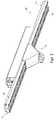
- FIG. 1shows a schematic view of a preferred embodiment of a second optical arrangement 10 according to the invention, which in the FIGS. 2 to 4 is releasably secured to an elongated lighting device 100.
- the preferred embodiment of the second optical arrangement 10comprises a substantially funnel-shaped main body 11, wherein a lens element 12 is arranged in the form of a Fresnel lens on a lower side provided for emitting light, which bundles the light and emits with a lens-dependent angle to the vertical.
- the optical arrangement 10On the opposite side of the lens element 12, the optical arrangement 10 has two opposing locking lugs 13, with which the optical arrangement 10 at the in the FIGS. 2 to 4 shown elongated lighting device 100 can be releasably secured.
- the upper side of the optical device 10is formed open so that light from the elongated lighting device 100 can enter the optical device 10 in this region.
- the light entry surface formed in the upper regioncan enter light from the elongated lighting device 100 in the optical assembly 10, seen in plan view formed substantially rectangular.
- the light exit surface, on which light can exit from the optical arrangement 10 or from the lens element 12,is substantially circular in plan view.
- the lens element 12bundles the light entering the optical arrangement 10 such that the optical arrangement 10 is perceived as light point sources, such as a radiator module or a spotlight module, and can be used accordingly.
- optical elementssuch as a reflector arrangement, a lens arrangement or other light-guiding elements can be provided, which serve to light the light entering at the upper light entry surface up to the lens element 12 to lead it out of the optical arrangement can escape.
- the lens element 12is preferably rotatably arranged on the base body 11, so that the exact light emission direction of the radiation cone can be changed accordingly.
- the illustrated substantially rectangular shaped light entry surface of the optical arrangement 10represents a particularly preferred form of the light entry surface, as this can be done by a particularly simple attachment of the light entry surface on the elongated lighting device 100.
- the optical arrangement and / or the lens elementessentially cylindrical, for example by means of cylindrical or rod-shaped light-guiding elements.
- the optical arrangement or the lens element of the optical arrangementcan be arranged to be rotatable so that a light emission can occur depending on the angular positioning of the lens element or the optical arrangement.
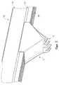
- the elongate lighting device 100comprises, on the light exit side, an optical arrangement 110 in the form of diffuser elements.
- the elongate lighting device 100may comprise further optical elements / devices, such as, for example, reflector arrangements, diffusing screens, milk glass panes or the like.
- the elongated lighting device 100further comprises at least one elongated light source (not shown) provided behind the optical assembly 110.
- the optical arrangement 110 and the at least one light sourceare arranged in a housing 113 of the elongate lighting device 100.
- the elongated lighting device 100comprises two opposing locking grooves 111, in which the correspondingly formed locking lugs 13 of the optical assembly 10 is engaged can be and thus the optical assembly 10 can be attached to the elongated lighting device 100.
- the latching grooves 111 of the elongated lighting device 100extend substantially over the entire longitudinal extent of the elongated lighting device 100, so that the positioning of the optical arrangement 10 is essentially freely selectable.
- detent connections 13, 111 showncan be provided in order to detach the optical arrangement 10 to the housing 113 or to the optical arrangement 110 the elongated lighting device 100 to connect.
- the detachable attachment of the optical arrangement 10 in the beam path behind the optical arrangement 110 of the elongated lighting device 100thus provides an easy way to provide an elongated lighting device 100 with an additional radiation characteristic without having to structurally modify the existing lighting device. Also, no electrical contacts are necessary because the optical assembly 10 does not require active light sources and utilizes only the radiated light of the elongated light emitting device 100. As a result, an elongated lighting device with a further emission characteristic, in particular a radiator function, can thus be provided in a simple manner and this while avoiding the known disadvantages. It is also possible to retrofit already built-in elongated lighting devices in a simple way with an additional emission characteristics.
Landscapes
- Engineering & Computer Science (AREA)
- General Engineering & Computer Science (AREA)
- Non-Portable Lighting Devices Or Systems Thereof (AREA)
Abstract
Translated fromGermanDescription
Translated fromGermanDie vorliegende Erfindung betrifft eine längliche Leuchtvorrichtung, insbesondere eine Lichtbandleuchte, und eine optische Anordnung zur lösbaren Befestigung an einer länglichen Leuchtvorrichtung.The present invention relates to an elongated lighting device, in particular a continuous line luminaire, and an optical arrangement for releasable attachment to an elongate lighting device.
Aus dem Stand der Technik ist eine Vielzahl von länglichen Leuchtvorrichtungen bekannt, beispielsweise in Form von länglichen Lichtbandleuchten mit länglichen Leuchtstoffröhren oder länglichen LED-Arrays. Die bekannten Leuchtvorrichtungen sind dabei typischerweise mittels einzelner Leuchtmodule, die eine vordefinierte Länge aufweisen, aufgebaut bzw. zusammengesetzt. Derartige Leuchtvorrichtungen umfassen darüber hinaus häufig optische Anordnungen, wie Reflektoren oder Milchglasscheiben, um ein gerichtetes oder diffuses Licht durch die Leuchtvorrichtung abgeben zu können.From the prior art, a variety of elongated lighting devices are known, for example in the form of elongated continuous line lights with elongated fluorescent tubes or elongated LED arrays. The known lighting devices are typically constructed or assembled by means of individual lighting modules having a predefined length. In addition, such lighting devices often include optical arrangements, such as reflectors or frosted glass panes, in order to be able to emit a directed or diffused light through the lighting device.
Ferner ist es im Stand der Technik bekannt, dass einzelne Leuchtmodule der länglichen Leuchtvorrichtung nachträglich abgenommen werden und durch andere Leuchtmodule, die eine andere Abstrahlcharakteristik aufweisen, ersetzt werden können. In diesem Zusammenhang ist es insbesondere bekannt eines oder mehrere der Leuchtmodule mit länglichen Lichtquellen durch Leuchtmodule mit Lichtpunktquellen, wie Strahlermodule, Spot-Light-Module oder dergleichen, zu ersetzen, um in einzelnen Bereichen eine entsprechende Beleuchtung bereitstellen zu können.Furthermore, it is known in the prior art that individual lighting modules of the elongated lighting device are subsequently removed and can be replaced by other lighting modules which have a different emission characteristic. In this context, it is known in particular to replace one or more of the lighting modules with elongate light sources by lighting modules with light point sources, such as radiator modules, spot light modules or the like, in order to be able to provide corresponding illumination in individual areas.
Nachdem die einzelnen Leuchtmodule der länglichen Leuchtvorrichtung häufig allerdings eine vordefinierte Länge aufweisen und für einen Austausch zumindest ein derartiges Leuchtmodul entfernt werden muss, können sich durch den Austausch der Leuchtmodule unerwünschte Beleuchtungslücken ergeben, die den Beleuchtungseindruck der länglichen Leuchtvorrichtung nachteilig beeinflussen.After the individual lighting modules of the elongated lighting device, however, often have a predefined length and at least one such light module must be removed for replacement, can result from the replacement of the lighting modules unwanted lighting gaps that adversely affect the lighting impression of the elongated lighting device.
Darüber hinaus ist der Austausch der Leuchtmodule vergleichsweise aufwändig, insbesondere da hierbei die elektrischen Kontaktierungen des auszutauschenden Leuchtmoduls zunächst entfernt und am einzusetzenden Leuchtmodul erneut angebracht werden müssen. Darüber hinaus sind die elektrischen Kontaktierungen häufig auch nur an vordefinierten Positionen an der länglichen Leuchtvorrichtung angeordnet, was die Positionierungsmöglichkeiten für die alternativen Leuchtmodule weiter einschränkt.In addition, the replacement of the lighting modules is relatively complex, especially since in this case the electrical contacts of the light module to be replaced must first be removed and reapplied to the light module to be used. In addition, the electrical contacts often also arranged only at predefined positions on the elongated lighting device, which further limits the positioning options for the alternative lighting modules.
Ausgehend von diesem Stand der Technik stellt sich die vorliegende Erfindung die Aufgabe, eine längliche Leuchtvorrichtung bereitzustellen, an der in einfacher Weise in einzelnen Bereichen eine veränderte Abstrahlcharakteristik, vorzugsweise eine Strahlerfunktion, optional bereitgestellt werden kann.Based on this prior art, the present invention has the object to provide an elongated lighting device on which in a simple manner in individual areas a modified emission, preferably a radiator function, can optionally be provided.
Diese und andere Aufgaben, die beim Lesen der folgenden Beschreibung noch genannt werden oder vom Fachmann erkannt werden können, werden durch den Gegenstand der unabhängigen Ansprüche gelöst. Die abhängigen Ansprüche bilden den zentralen Gedanken der vorliegenden Erfindung in besonders vorteilhafterweise weiter.These and other objects, which will become apparent upon reading the following description or which will be recognized by those skilled in the art, are achieved by the subject-matter of the independent claims. The dependent claims further form the central idea of the present invention in a particularly advantageous manner.
Eine erfindungsgemäße längliche Leuchtvorrichtung, insbesondere eine Lichtbandleuchte, umfasst: zumindest eine Lichtquelle; zumindest eine erste optische Anordnung, die in Abstrahlrichtung der Lichtquelle (gesehen) hinter der Lichtquelle angeordnet ist; zumindest eine separate zweite optische Anordnung, die in Abstrahlrichtung der Lichtquelle (gesehen) hinter der ersten optischen Anordnung lösbar an der Leuchtvorrichtung angeordnet ist, und zwar derart, dass das aus der ersten optischen Anordnung austretende Licht teilweise in die zweite optische Anordnung eintreten kann, so dass die Leuchtvorrichtung Licht aus der ersten optischen Anordnung und Licht aus der zweiten optischen Anordnung abgeben kann.An elongate lighting device according to the invention, in particular a continuous-line luminaire, comprises: at least one light source; at least one first optical arrangement, which is arranged in the emission direction of the light source (seen) behind the light source; at least one separate second optical arrangement, which is arranged in the emission direction of the light source (seen) behind the first optical arrangement detachably on the lighting device, in such a way that the light emerging from the first optical arrangement can partially enter the second optical arrangement, so in that the lighting device can emit light from the first optical arrangement and light from the second optical arrangement.
Mit anderen Worten schlägt die vorliegende Erfindung vor, auf eine erste optische Anordnung der länglichen Leuchtvorrichtung, beispielsweise eine Reflektoranordnung, eine Streuscheibe oder ein sonstiges Diffusormittel, eine zweite, separate optische Anordnung lösbar anzuordnen und im Gegensatz zu den bekannten Lösungen keinen Austausch der Leuchtmodule mehr vorzunehmen. Der Begriff der zweiten optischen Anordnung ist dabei breit zu verstehen und umfasst nicht nur optische Element, wie beispielsweise Linsen, Lichtleitmittel, sondern auch Gehäuse, Befestigungsmittel und dergleichen. Insbesondere ist unter der zweiten optischen Anordnung die gesamte an der länglichen Leuchtvorrichtung anordenbare Baueinheit zu verstehen.In other words, the present invention proposes to detachably arrange a second, separate optical arrangement on a first optical arrangement of the elongate lighting device, for example a reflector arrangement, a diffusing screen or another diffuser, and, unlike the known solutions, no longer replace the lighting modules , The term of the second optical arrangement is to be understood broadly and includes not only optical elements, such as lenses, light guide, but also housing, fasteners and the like. In particular, the second optical arrangement means the entire unit which can be arranged on the elongate lighting device.
In der einfachsten Ausführungsform handelt es sich bei der zweiten optischen Anordnung um ein Gehäuse mit zumindest einem optischen Element, das in Längserstreckung an einer beliebigen Position auf die längliche Leuchtvorrichtung aufclipsbar ist. Dadurch kann das von der Lichtquelle der länglichen Leuchtvorrichtung ausgestrahlte Licht quasi abgezweigt werden und durch das optische Element der zweiten optischen Anordnung geführt werden. Das optische Element der zweiten optischen Anordnung, beispielsweise eine Sammellinse oder eine Fresnellinse, ist vorzugsweise derart gewählt, dass eine gebündelte Lichtabgabe durch die zweite optische Anordnung möglich ist, um an der länglichen Leuchtvorrichtung zusätzlich zumindest eine Strahlerfunktion bereitstellen zu können.In the simplest embodiment, the second optical arrangement is a housing with at least one optical element, which in Longitudinal extension at any position on the elongated lighting device can be clipped. As a result, the light emitted by the light source of the elongate lighting device can be quasi branched off and guided through the optical element of the second optical arrangement. The optical element of the second optical arrangement, for example a converging lens or a Fresnel lens, is preferably selected such that bundled light output by the second optical arrangement is possible in order to be able to additionally provide at least one radiator function on the elongate lighting device.
Das lösbare Anbringen der zweiten optischen Anordnung im Strahlengang hinter der ersten optischen Anordnung, anstatt eines Austausches von Leuchtmodulen, weist insbesondere den Vorteil auf, dass die bestehende Leuchtvorrichtung nicht strukturell verändert werden muss, um einen Bereich mit einer veränderten Abstrahlcharakteristik bereitstellen zu können. Auch sind keine elektrischen Kontaktierungen für die zweite optische Anordnung notwendig, da die zweite optische Anordnung das abgestrahlte Licht der länglichen Leuchtvorrichtung nutzt und keine eigenen aktiven Lichtquellen umfasst. Im Vergleich zu den bisher bekannten Lösungen kann somit auf einfache Weise eine längliche Leuchtvorrichtung mit einer weiteren Abstrahlcharakteristik, insbesondere einer Strahlerfunktion, bereitgestellt werden und dies unter Vermeidung der oben beschriebenen Nachteile.The detachable attachment of the second optical arrangement in the beam path behind the first optical arrangement, instead of an exchange of lighting modules, has the particular advantage that the existing lighting device does not need to be structurally changed in order to provide a region with a modified radiation characteristic can. Also, no electrical contacts are necessary for the second optical arrangement, since the second optical arrangement uses the radiated light of the elongated lighting device and does not comprise its own active light sources. In comparison to the previously known solutions, an elongated lighting device with a further emission characteristic, in particular a radiator function, can thus be provided in a simple manner and this while avoiding the disadvantages described above.
Vorzugsweise umfasst die längliche Leuchtvorrichtung ein Gehäuse, in dem bzw. an dem die zumindest eine Lichtquelle und die zumindest eine erste optische Anordnung fest angeordnet sind, wobei die Lichtquelle der länglichen Leuchtvorrichtung vorzugsweise ein längliches LED-Array oder eine längliche Leuchtstoffröhre ist.Preferably, the elongated lighting device comprises a housing in which the at least one light source and the at least one first optical arrangement are fixed, wherein the light source of the elongated lighting device is preferably an elongated LED array or an elongate fluorescent tube.
Dabei ist es besonders bevorzugt, dass die zweite optische Anordnung an dem Gehäuse der länglichen Leuchtvorrichtung oder an der ersten optischen Anordnung lösbar angeordnet ist bzw. angeordnet werden kann. In diesem Zusammenhang ist es weiterhin bevorzugt, dass die zweite optische Anordnung zumindest ein Rast-/Federelement aufweist, um diese lösbar mit einem korrespondierenden Rast-/Federelement des Gehäuses und/oder der ersten optischen Anordnung zu verbinden. Ferner ist es besonders bevorzugt, dass das Rast-/Federelement des Gehäuses und/oder der ersten optischen Anordnung sich im Wesentlichen über die gesamte Längserstreckung der länglichen Leuchtvorrichtung erstreckt, so dass die zweite optische Anordnung im Wesentlichen an der gesamten Längserstreckung der länglichen Leuchtvorrichtung lösbar anordenbar ist. Die Rast-/Federelemente sind vorzugsweise als Feder-Nut-Verbindungen, als Clips-Verbindungen und/oder als Federstift-Verbindungen ausgebildet.It is particularly preferred that the second optical arrangement on the housing of the elongate lighting device or on the first optical arrangement is detachably arranged or can be arranged. In this context, it is further preferred that the second optical arrangement has at least one latching / spring element in order to releasably connect it to a corresponding latching / spring element of the housing and / or the first optical arrangement. Furthermore, it is particularly preferred that the latching / spring element of the housing and / or the first optical arrangement extends substantially over the entire longitudinal extension of the elongate lighting device, so that the second optical arrangement can be arranged detachably substantially over the entire longitudinal extent of the elongate lighting device is. The locking / spring elements are preferably designed as tongue and groove connections, as clip connections and / or as spring pin connections.
Vorteilhafterweise ist die zweite optische Anordnung in Längserstreckung der länglichen Leuchtvorrichtung gleitverschieblich am Gehäuse und/oder an der ersten optischen Anordnung angeordnet. Dies kann beispielsweise durch eine über die gesamte Längserstreckung der länglichen Leuchtvorrichtung vorgesehene Hinterschneidung/Rastnut erfolgen, an der die zweite optische Anordnung mittels korrespondierend ausgebildeter Rastmittel angeordnet werden kann.Advantageously, the second optical arrangement in the longitudinal extent of the elongated lighting device is slidably disposed on the housing and / or on the first optical arrangement. This can be done for example by an over the entire longitudinal extent of the elongated lighting device provided undercut / detent groove on which the second optical arrangement can be arranged by means of correspondingly formed locking means.
Ferner ist es besonders bevorzugt, dass die zweite optische Anordnung und/oder das Linsenelement der zweiten optischen Anordnung dreh- und/oder kippbar angeordnet ist, um die Lichtabstrahlrichtung des aus der zweiten optischen Anordnung austretenden Lichts verändern zu können. Eine derartige Beweglichkeit kann insbesondere durch Dreh- oder Kippmechanismen bereitgestellt werden. Beispielsweise kann es sich bei dem Linsenelement um eine Fresnellinse handeln, die drehbar an der zweiten optischen Anordnung, beispielsweise im Gehäuse der zweiten optischen Anordnung, befestigt ist.Furthermore, it is particularly preferred that the second optical arrangement and / or the lens element of the second optical arrangement is arranged rotatable and / or tiltable in order to be able to change the light emission direction of the light emerging from the second optical arrangement. Such mobility can be provided in particular by turning or tilting mechanisms. For example, the lens element may be a Fresnel lens, which is rotatably attached to the second optical arrangement, for example in the housing of the second optical arrangement.
Die zweite optische Anordnung umfasst vorzugsweise Lichtleitmittel, wie beispielsweise zumindest eine Reflektorfläche, und ein Linsenelement, das derart ausgebildet ist, um das in die zweite optische Anordnung eintretende Licht zum Linsenelement zu führen. Insbesondere können am oder im Gehäuse der zweiten optischen Anordnung reflektierende Beschichtungen/Oberflächen vorgesehen sein, um das von der Lichtquelle der länglichen Leuchtvorrichtung erhaltene Licht zum optischen Element der zweiten optischen Anordnung zu leiten. Alternativ oder zusätzlich besteht die Möglichkeit noch weitere Lichtleitmittel, wie Linsenanordnungen, Prismen, Lichtwellenleiter und dergleichen in der zweiten optischen Anordnung vorzusehen.The second optical arrangement preferably comprises light-guiding means, such as at least one reflector surface, and a lens element adapted to guide the light entering the second optical arrangement to the lens element. In particular, reflective coatings / surfaces can be provided on or in the housing of the second optical arrangement in order to guide the light obtained from the light source of the elongate lighting device to the optical element of the second optical arrangement. Alternatively or additionally, it is possible to provide further light-conducting means, such as lens arrangements, prisms, optical waveguides and the like in the second optical arrangement.
Die zweite optische Anordnung bzw. das Gehäuse der zweiten optischen Anordnung ist vorzugsweise im Wesentlichen trichterförmig, zylindrisch oder stabförmig ausgebildet. Bei einer im Wesentlichen trichterförmigen Ausbildung ist es besonders bevorzugt, dass es sich dabei um eine Trichterform mit einer rechteckförmigen Grundfläche handelt, die mit der Fläche der länglichen Leuchtvorrichtung korrespondiert, an der die zweite optische Anordnung an der länglichen Leuchtvorrichtung angeordnet ist/wird. Bei einer im Wesentlichen zylindrischen Ausbildung der zweiten optischen Anordnung besteht die Möglichkeit das optische Element der zweiten optischen Anordnung, beispielsweise ausgebildet als zylinderförmiges oder stabförmiges Lichtleitelement, derart auszubilden und in dem Zylinder drehbar anzuordnen, dass eine Lichtabgabe in Abhängigkeit der Winkelpositionierung des optischen Elements erfolgen kann. Zusätzlich oder alternativ besteht bei einer zylindrischen Ausbildung der zweiten optischen Anordnung ferner die Möglichkeit, die gesamte Anordnung drehbar an der länglichen Leuchtvorrichtung zu lagern und eine Lichtabgabe entsprechend der Winkelpositionierung der zweiten optischen Anordnung zu variieren.The second optical arrangement or the housing of the second optical arrangement is preferably substantially funnel-shaped, cylindrical or rod-shaped. In a substantially funnel-shaped embodiment, it is particularly preferred that this is a funnel shape with a rectangular base surface, which corresponds to the surface of the elongated lighting device on which the second optical arrangement is arranged on the elongate lighting device / is. In a substantially cylindrical design of the second optical arrangement, the possibility exists of the optical element of the second optical Arrangement, for example, designed as a cylindrical or rod-shaped light guide, such form and rotatably arranged in the cylinder, that a light output can be carried out in dependence of the angular positioning of the optical element. Additionally or alternatively, in the case of a cylindrical design of the second optical arrangement, it is also possible to mount the entire arrangement rotatably on the elongate lighting device and to vary a light output in accordance with the angular positioning of the second optical arrangement.
Die Lichteintrittsfläche der zweiten optischen Anordnung, an der Licht von der ersten optischen Anordnung in das zweite optische Element eintritt, weist vorzugsweise in Draufsicht gesehen im Wesentlichen eine Rechteckform auf, wobei die Lichtaustrittsfläche der zweiten optischen Anordnung, an der Licht aus der zweiten optischen Anordnung austritt oder zum Linsenelement der zweiten optischen Anordnung geführt wird, in Draufsicht gesehen vorzugsweise im Wesentlichen eine Kreisform aufweist.The light entry surface of the second optical arrangement, at which light enters from the first optical arrangement into the second optical element, preferably has a substantially rectangular shape when viewed in plan view, the light exit area of the second optical arrangement, at which light emerges from the second optical arrangement or is guided to the lens element of the second optical arrangement, seen in plan view preferably has a substantially circular shape.
Ferner betrifft die vorliegende Erfindung eine oben beschriebene zweite optische Anordnung, wobei die optische Anordnung eingerichtet ist, um an der länglichen Leuchtvorrichtung, die zumindest eine Lichtquelle und eine erste optische Anordnung umfasst, in Abstrahlrichtung hinter der ersten optischen Anordnung lösbar an der Leuchtvorrichtung angeordnet zu werden, und zwar derart, dass das aus der ersten optischen Anordnung austretende Licht teilweise in die zweite optische Anordnung eintreten kann, so dass die Leuchtvorrichtung Licht aus der ersten optischen Anordnung und Licht aus der zweiten optischen Anordnung abgeben kann.Furthermore, the present invention relates to a second optical arrangement described above, wherein the optical arrangement is arranged to be arranged on the elongated lighting device comprising at least one light source and a first optical arrangement, releasably attached to the lighting device in the emission direction behind the first optical arrangement in such a way that the light emerging from the first optical arrangement can partially enter the second optical arrangement so that the lighting device can emit light from the first optical arrangement and emit light from the second optical arrangement.
Nachfolgend wird eine detaillierte Beschreibung der Figuren gegeben. Darin zeigt:
- Figur 1
- eine schematische Ansicht einer bevorzugten Ausführungsform einer erfindungsgemäßen zweiten optischen Anordnung, die an einer länglichen Leuchtvorrichtung lösbar befestigt werden kann;
- Figur 2
- eine schematische Ansicht einer bevorzugten Ausführungsform einer erfindungsgemäßen länglichen Leuchtvorrichtung, an der die zweite optische Anordnung aus
Figur 1 befestigt ist; - Figur 3
- eine schematische Teilansicht der in
Figur2 gezeigten länglichen Leuchtvorrichtung; - Figur 4
- eine schematische Teilansicht der in
Figur2 gezeigten länglichen Leuchtvorrichtung.
- FIG. 1
- a schematic view of a preferred embodiment of a second optical arrangement according to the invention, which can be releasably attached to an elongated lighting device;
- FIG. 2
- a schematic view of a preferred embodiment of an elongated lighting device according to the invention, on which the second optical arrangement of
FIG. 1 is attached; - FIG. 3
- a schematic partial view of in
FIG.2 shown elongated lighting device; - FIG. 4
- a schematic partial view of in
FIG.2 shown elongated lighting device.
Die bevorzugte Ausführungsform der zweiten optischen Anordnung 10 umfasst einen im Wesentlichen trichterförmigen Grundkörper 11, wobei an einer zur Lichtabgabe vorgesehenen unteren Seite ein Linsenelement 12 in Form einer Fresnellinse angeordnet ist, die das Licht bündelt und mit einem linsenabhängigen Winkel zur senkrechten abgibt.The preferred embodiment of the second
An der dem Linsenelement 12 gegenüberliegenden Seite weist die optische Anordnung 10 zwei sich gegenüberliegende Rastnasen 13 auf, mit der die optische Anordnung 10 an der in den
Wie in
Im Inneren oder an der optischen Anordnung 10 (vorzugsweise im Grundkörper 11 der optischen Anordnung 10) können weiter optische Elemente, wie eine Reflektoranordnung, eine Linsenanordnung oder sonstige Lichtleitelemente vorgesehen sein, die dazu dienen, das an der oberen Lichteintrittsfläche eintretende Licht bis zum Linsenelement 12 zu führen, wo es aus der optischen Anordnung austreten kann. Das Linsenelement 12 ist vorzugsweise drehbar am Grundkörper 11 angeordnet, so dass die genaue Lichtabgaberichtung des Strahlungskegels entsprechend verändert werden kann. In diesem Zusammenhang kann es von Vorteil sein, noch weitere Schwenk- und/oder Kippeinrichtungen an der optischen Anordnung 10 bzw. am Linsenelement 12 vorzusehen, um die Lichtabgaberichtung noch weiter variieren zu können.In the interior or on the optical arrangement 10 (preferably in the
Die gezeigte im Wesentlichen rechteckförmig ausgebildete Lichteintrittsfläche der optischen Anordnung 10 stellt eine besonders bevorzugte Form der Lichteintrittsfläche dar, da dadurch eine besonders einfache Anbringung der Lichteintrittsfläche an der länglichen Leuchtvorrichtung 100 erfolgen kann. Alternativ zur gezeigten im Wesentlichen trichterförmigen Ausbildung der optischen Anordnung 10 mit dem lichtaustrittsseitig angeordneten Linsenelement 12, besteht auch die Möglichkeit die optische Anordnung und/oder das Linsenelement im Wesentlichen zylindrisch auszubilden, beispielsweise mittels zylinderförmiger oder stabförmiger Lichtleitelementen. Dabei kann die optische Anordnung oder das Linsenelement der optischen Anordnung derart drehbar angeordnet werden, so dass eine Lichtabgabe in Abhängigkeit der Winkelpositionierung des Linsenelements oder der optischen Anordnung erfolgen kann.The illustrated substantially rectangular shaped light entry surface of the
Nachfolgend wird eine bevorzugte Ausführungsform einer erfindungsgemäßen länglichen Leuchtvorrichtung 100, an der die in
Wie in den
Wie in den
Alternativ oder zusätzlich zu den gezeigten Rastverbindungen 13, 111 können auch andere Rast-/Federelement, Feder-Nut-Verbindungen, Clips-Verbindungen oder Federstift-Verbindungen vorgesehen werden, um die optische Anordnung 10 lösbar mit dem Gehäuse 113 oder mit der optischen Anordnung 110 der länglichen Leuchtvorrichtung 100 zu verbinden.Alternatively or in addition to the
Durch das lösbare Anbringen der optischen Anordnung 10 im Strahlengang hinter der optischen Anordnung 110 der länglichen Leuchtvorrichtung 100 kann somit eine einfache Möglichkeit bereitgestellt werden, eine längliche Leuchtvorrichtung 100 mit einer zusätzlichen Abstrahlcharakteristik bereitzustellen, ohne dass die bestehende Leuchtvorrichtung strukturell verändert werden müsste. Auch sind keine elektrischen Kontaktierungen notwendig, da die optische Anordnung 10 keine aktiven Lichtquellen benötigt und nur das abgestrahlte Licht der länglichen Leuchtvorrichtung 100 nutzt. Im Ergebnis kann somit auf einfache Weise eine längliche Leuchtvorrichtung mit einer weiteren Abstrahlcharakteristik, insbesondere einer Strahlerfunktion, bereitgestellt werden und dies unter Vermeidung der bekannten Nachteile. Auch besteht die Möglichkeit bereits eingebaute längliche Leuchtvorrichtungen auf einfache Weise mit einer zusätzlichen Abstrahlcharakteristik nachzurüsten.The detachable attachment of the
Die vorliegende Erfindung ist nicht auf das vorhergehende Ausführungsbeispiel beschränkt, solange sie vom Gegenstand der folgenden Ansprüche umfasst ist. Insbesondere ist anzumerken, dass die vorliegende Erfindung nicht auf eine spezielle Form der zweiten optischen Anordnung beschränkt ist.The present invention is not limited to the foregoing embodiment as long as it is encompassed by the subject matter of the following claims. In particular, it should be noted that the present invention is not limited to any particular form of the second optical arrangement.
Claims (16)
Translated fromGermanwobei die erste optische Anordnung (110) ein Diffusorelement, insbesondere eine Streuscheibe, eine Reflektor-Anordnung umfasst.An elongated lighting device (100) according to any one of claims 1 or 2, wherein the light source is an elongated LED array or an elongate fluorescent tube, and / or
wherein the first optical arrangement (110) comprises a diffuser element, in particular a diffusing screen, a reflector arrangement.
wobei die zweite optische Anordnung (10) zumindest ein Linsenelement (12) umfasst, wobei die zweite optische Anordnung (10) darüber hinaus vorzugsweise Lichtleitmittel, wie beispielsweise eine Reflektoranordnung, umfasst, die derart ausgebildet sind, um das in die zweite optische Anordnung (10) eintretende Licht zum Linsenelement (12) zu führen, wobei das Linsenelement (12) der zweiten optischen Anordnung (10) vorzugsweise eine Fresnel-Struktur umfasst.An elongated light-emitting device (100) according to one of the preceding claims, wherein the second optical arrangement (10) bundles and directs the light entering from the first optical arrangement (110), in particular as a directed light cone, and / or
wherein the second optical assembly (10) comprises at least one lens element (12), the second optical assembly (10) further preferably including light guiding means, such as a reflector assembly, configured to fit into the second optical assembly (10 ) to lead light to the lens element (12), wherein the lens element (12) of the second optical arrangement (10) preferably comprises a Fresnel structure.
wobei die zweite optische Anordnung (10) vorzugsweise zumindest ein Rast-/Federelement (13) aufweist, um die zweite optische Anordnung (10) lösbar mit einem korrespondierenden Rast-/Federelement (111) des Gehäuses (113) und/oder der ersten optischen Anordnung (110) zu verbinden,
wobei sich vorzugsweise die Rast-/Federelemente (111) des Gehäuses (113) und/oder der ersten optischen Anordnung (110) im Wesentlichen über die gesamte Längserstreckung der länglichen Leuchtvorrichtung (100) erstreckt, so dass die zweite optische Anordnung (10) im Wesentlichen an der gesamten Längserstreckung der länglichen Leuchtvorrichtung (100) lösbar anordenbar ist, wobei vorzugsweise die Rast-/Federelemente (13, 111) als Feder-Nut-Verbindungen, als Clips-Verbindungen und/oder als Federstift-Verbindungen ausgebildet sind.An elongated light-emitting device (100) according to one of the preceding claims, wherein the second optical arrangement (10) is detachably arranged on the housing (113) of the elongate lighting device (100) or on the first optical arrangement (110),
wherein the second optical arrangement (10) preferably has at least one latching / spring element (13) for releasably releasing the second optical arrangement (10) with a corresponding latching / spring element (111) of the housing (113) and / or the first optical system To connect arrangement (110)
wherein preferably the detent / spring elements (111) of the housing (113) and / or the first optical arrangement (110) extends substantially over the entire longitudinal extent of the elongate lighting device (100), so that the second optical arrangement (10) in Substantially on the entire longitudinal extension of the elongated lighting device (100) can be arranged detachably, wherein preferably the latching / spring elements (13, 111) are designed as tongue and groove connections, as clip connections and / or as spring pin connections.
wobei die optische Anordnung (10) vorzugsweise zumindest ein Rast-/Federelement (13) umfasst, um die optische Anordnung (10) lösbar mit einem korrespondierenden Rast-/Federelement (111) des Gehäuses (113) und/oder der ersten optischen Anordnung (110) zu verbinden, wobei vorzugsweise das zumindest eine Rast-/Federelement (13) als Feder-Nut-Verbindung, als Clips-Verbindung und/oder als Federstift-Verbindung ausgebildet ist.An optical assembly (10) according to any one of claims 10 to 14, wherein the optical assembly (10) is detachably mountable to a housing of the elongated light emitting device (100) or to the first optical assembly (110).
wherein the optical arrangement (10) preferably comprises at least one latching / spring element (13) for releasably releasing the optical arrangement (10) with a corresponding latching / spring element (111) of the housing (113) and / or the first optical arrangement (11). 110), wherein preferably the at least one latching / spring element (13) is designed as a spring-groove connection, as a clip connection and / or as a spring pin connection.
Applications Claiming Priority (1)
| Application Number | Priority Date | Filing Date | Title |
|---|---|---|---|
| DE102015207987.2ADE102015207987A1 (en) | 2015-04-30 | 2015-04-30 | lighting device |
Publications (2)
| Publication Number | Publication Date |
|---|---|
| EP3088795A1true EP3088795A1 (en) | 2016-11-02 |
| EP3088795B1 EP3088795B1 (en) | 2018-03-14 |
Family
ID=56024093
Family Applications (1)
| Application Number | Title | Priority Date | Filing Date |
|---|---|---|---|
| EP16166564.1AActiveEP3088795B1 (en) | 2015-04-30 | 2016-04-22 | Lighting device |
Country Status (3)
| Country | Link |
|---|---|
| EP (1) | EP3088795B1 (en) |
| AT (1) | AT16244U1 (en) |
| DE (1) | DE102015207987A1 (en) |
Cited By (1)
| Publication number | Priority date | Publication date | Assignee | Title |
|---|---|---|---|---|
| CN110906189A (en)* | 2018-09-17 | 2020-03-24 | 光宝电子(广州)有限公司 | Lighting device |
Citations (7)
| Publication number | Priority date | Publication date | Assignee | Title |
|---|---|---|---|---|
| US4616296A (en)* | 1985-08-07 | 1986-10-07 | Alkco Manufacturing Company | Lamp |
| WO2006087198A1 (en)* | 2005-02-17 | 2006-08-24 | Zumtobel Lighting Gmbh | Light comprising an elongate light source and a light-influencing element |
| US20100135027A1 (en)* | 2008-11-28 | 2010-06-03 | Foxsemicon Integrated Technology, Inc. | Anti-glare indoor lamp |
| WO2010106470A1 (en)* | 2009-03-18 | 2010-09-23 | Koninklijke Philips Electronics N.V. | Lighting system for a freezer cabinet and/or a refrigerator cabinet |
| DE202013100214U1 (en)* | 2012-01-20 | 2013-03-07 | Dafun Design Consultant Co., Ltd. | housing construction |
| DE102011082844A1 (en)* | 2011-09-16 | 2013-03-21 | Zumtobel Lighting Gmbh | Lighting arrangement, in particular for escape route lighting |
| EP2672171A1 (en)* | 2012-06-04 | 2013-12-11 | RIDI Leuchten GmbH | Light, in particular for a light ribbon |
Family Cites Families (5)
| Publication number | Priority date | Publication date | Assignee | Title |
|---|---|---|---|---|
| US7510305B2 (en)* | 2004-06-18 | 2009-03-31 | Abl Ip Holding Llc | Air-handling light fixture and lens assembly for same |
| BRPI0921473A2 (en)* | 2008-10-31 | 2016-01-12 | Code 3 Inc | luminaire with reflectors internal and external rails |
| DE202010008598U1 (en)* | 2010-09-21 | 2011-12-28 | Zumtobel Lighting Gmbh | Optical system and luminaire for direct and indirect lighting |
| DE102012006999A1 (en)* | 2012-04-10 | 2013-10-10 | Erco Gmbh | lamp |
| DE202013010408U1 (en)* | 2013-11-19 | 2015-02-20 | Zumtobel Lighting Gmbh | Luminaire optics and continuous line luminaire |
- 2015
- 2015-04-30DEDE102015207987.2Apatent/DE102015207987A1/ennot_activeWithdrawn
- 2015-09-08ATATGM267/2015Upatent/AT16244U1/ennot_activeIP Right Cessation
- 2016
- 2016-04-22EPEP16166564.1Apatent/EP3088795B1/enactiveActive
Patent Citations (7)
| Publication number | Priority date | Publication date | Assignee | Title |
|---|---|---|---|---|
| US4616296A (en)* | 1985-08-07 | 1986-10-07 | Alkco Manufacturing Company | Lamp |
| WO2006087198A1 (en)* | 2005-02-17 | 2006-08-24 | Zumtobel Lighting Gmbh | Light comprising an elongate light source and a light-influencing element |
| US20100135027A1 (en)* | 2008-11-28 | 2010-06-03 | Foxsemicon Integrated Technology, Inc. | Anti-glare indoor lamp |
| WO2010106470A1 (en)* | 2009-03-18 | 2010-09-23 | Koninklijke Philips Electronics N.V. | Lighting system for a freezer cabinet and/or a refrigerator cabinet |
| DE102011082844A1 (en)* | 2011-09-16 | 2013-03-21 | Zumtobel Lighting Gmbh | Lighting arrangement, in particular for escape route lighting |
| DE202013100214U1 (en)* | 2012-01-20 | 2013-03-07 | Dafun Design Consultant Co., Ltd. | housing construction |
| EP2672171A1 (en)* | 2012-06-04 | 2013-12-11 | RIDI Leuchten GmbH | Light, in particular for a light ribbon |
Cited By (1)
| Publication number | Priority date | Publication date | Assignee | Title |
|---|---|---|---|---|
| CN110906189A (en)* | 2018-09-17 | 2020-03-24 | 光宝电子(广州)有限公司 | Lighting device |
Also Published As
| Publication number | Publication date |
|---|---|
| AT16244U1 (en) | 2019-05-15 |
| DE102015207987A1 (en) | 2016-11-03 |
| EP3088795B1 (en) | 2018-03-14 |
Similar Documents
| Publication | Publication Date | Title |
|---|---|---|
| DE102006044019B4 (en) | reflector spotlight | |
| EP2042801B1 (en) | Light source with adjustable emission characteristics | |
| DE102007030186B4 (en) | Linear LED lamp and lighting system with the same | |
| AT518551B1 (en) | Automotive illuminating device | |
| DE102019217716B4 (en) | SLIM LAMP DEVICE FOR VEHICLES | |
| DE102012213844B4 (en) | Light module for vehicle headlights with two optical units and associated fastening devices | |
| DE102015115555A1 (en) | Lighting device, rear view device, footwell device and vehicle | |
| EP2314912A1 (en) | LED lamp with infinitely adjustable emission angle | |
| DE102010054922A1 (en) | Headlight for vehicle, comprises semiconductor light source, which is fastened at light source carrier, and optical element, which is arranged in light emission direction of semiconductor light source | |
| DE102014116983B4 (en) | LASER OPTICAL SYSTEM FOR A VEHICLE HEADLIGHT IN WHICH A BEAM LENS FOCUSING A LASER BEAM IS IN DIRECT CONTACT WITH A LUMINOUS BODY EXCITED BY THE LASER BEAM | |
| DE102015202745B4 (en) | vehicle lighting device | |
| DE102010041477A1 (en) | Arrangement for emitting light | |
| DE202013101824U1 (en) | Luminaire with adjustable light emission characteristic | |
| WO2013143514A1 (en) | Lamp | |
| DE102015121324A1 (en) | Lighting device for a motor vehicle | |
| DE102010004221A1 (en) | Street light with punctiform light sources, in particular LED light | |
| DE10261008A1 (en) | Signal and driving light headlights for rail vehicles | |
| EP3088795B1 (en) | Lighting device | |
| DE202015106256U1 (en) | Blendarme lighting technology | |
| DE102011119372B4 (en) | Lighting device for a motor vehicle with a displaceable carriage which protrudes partly through a heat sink of the lighting device and is used for displaceably fastening a lens of a light module, and motor vehicle with this lighting device | |
| DE102014226647A1 (en) | LED carrier with an LED and luminaire with such an LED carrier | |
| DE102013110344A1 (en) | Lighting device for vehicles | |
| DE102013215976A1 (en) | Headlamp assembly for generating a variable light distribution | |
| DE102019123515A1 (en) | Motor vehicle headlights with two projection light modules of different focal lengths and equally wide illuminated light exit lenses | |
| DE202005014363U1 (en) | Motor vehicle number plate has optical arrangement to collect and deflect light from a source onto the number plate |
Legal Events
| Date | Code | Title | Description |
|---|---|---|---|
| PUAI | Public reference made under article 153(3) epc to a published international application that has entered the european phase | Free format text:ORIGINAL CODE: 0009012 | |
| AK | Designated contracting states | Kind code of ref document:A1 Designated state(s):AL AT BE BG CH CY CZ DE DK EE ES FI FR GB GR HR HU IE IS IT LI LT LU LV MC MK MT NL NO PL PT RO RS SE SI SK SM TR | |
| AX | Request for extension of the european patent | Extension state:BA ME | |
| STAA | Information on the status of an ep patent application or granted ep patent | Free format text:STATUS: REQUEST FOR EXAMINATION WAS MADE | |
| 17P | Request for examination filed | Effective date:20170405 | |
| RBV | Designated contracting states (corrected) | Designated state(s):AL AT BE BG CH CY CZ DE DK EE ES FI FR GB GR HR HU IE IS IT LI LT LU LV MC MK MT NL NO PL PT RO RS SE SI SK SM TR | |
| REG | Reference to a national code | Ref country code:DE Ref legal event code:R079 Ref document number:502016000688 Country of ref document:DE Free format text:PREVIOUS MAIN CLASS: F21S0004000000 Ipc:F21V0005040000 | |
| RIC1 | Information provided on ipc code assigned before grant | Ipc:F21V 13/04 20060101ALI20170727BHEP Ipc:F21S 4/00 20160101ALI20170727BHEP Ipc:F21V 17/00 20060101ALI20170727BHEP Ipc:F21V 5/04 20060101AFI20170727BHEP Ipc:F21Y 115/10 20160101ALI20170727BHEP Ipc:F21V 17/02 20060101ALI20170727BHEP Ipc:F21V 5/00 20150101ALI20170727BHEP Ipc:F21Y 103/00 20160101ALI20170727BHEP | |
| GRAP | Despatch of communication of intention to grant a patent | Free format text:ORIGINAL CODE: EPIDOSNIGR1 | |
| STAA | Information on the status of an ep patent application or granted ep patent | Free format text:STATUS: GRANT OF PATENT IS INTENDED | |
| INTG | Intention to grant announced | Effective date:20171031 | |
| GRAS | Grant fee paid | Free format text:ORIGINAL CODE: EPIDOSNIGR3 | |
| GRAA | (expected) grant | Free format text:ORIGINAL CODE: 0009210 | |
| STAA | Information on the status of an ep patent application or granted ep patent | Free format text:STATUS: THE PATENT HAS BEEN GRANTED | |
| AK | Designated contracting states | Kind code of ref document:B1 Designated state(s):AL AT BE BG CH CY CZ DE DK EE ES FI FR GB GR HR HU IE IS IT LI LT LU LV MC MK MT NL NO PL PT RO RS SE SI SK SM TR | |
| REG | Reference to a national code | Ref country code:GB Ref legal event code:FG4D Free format text:NOT ENGLISH | |
| REG | Reference to a national code | Ref country code:CH Ref legal event code:EP Ref country code:AT Ref legal event code:REF Ref document number:979256 Country of ref document:AT Kind code of ref document:T Effective date:20180315 | |
| REG | Reference to a national code | Ref country code:CH Ref legal event code:NV Representative=s name:FELBER UND PARTNER AG, CH | |
| REG | Reference to a national code | Ref country code:IE Ref legal event code:FG4D Free format text:LANGUAGE OF EP DOCUMENT: GERMAN | |
| REG | Reference to a national code | Ref country code:DE Ref legal event code:R096 Ref document number:502016000688 Country of ref document:DE | |
| REG | Reference to a national code | Ref country code:FR Ref legal event code:PLFP Year of fee payment:3 | |
| REG | Reference to a national code | Ref country code:NL Ref legal event code:MP Effective date:20180314 | |
| REG | Reference to a national code | Ref country code:LT Ref legal event code:MG4D | |
| PG25 | Lapsed in a contracting state [announced via postgrant information from national office to epo] | Ref country code:HR Free format text:LAPSE BECAUSE OF FAILURE TO SUBMIT A TRANSLATION OF THE DESCRIPTION OR TO PAY THE FEE WITHIN THE PRESCRIBED TIME-LIMIT Effective date:20180314 Ref country code:CY Free format text:LAPSE BECAUSE OF FAILURE TO SUBMIT A TRANSLATION OF THE DESCRIPTION OR TO PAY THE FEE WITHIN THE PRESCRIBED TIME-LIMIT Effective date:20180314 Ref country code:LT Free format text:LAPSE BECAUSE OF FAILURE TO SUBMIT A TRANSLATION OF THE DESCRIPTION OR TO PAY THE FEE WITHIN THE PRESCRIBED TIME-LIMIT Effective date:20180314 Ref country code:NO Free format text:LAPSE BECAUSE OF FAILURE TO SUBMIT A TRANSLATION OF THE DESCRIPTION OR TO PAY THE FEE WITHIN THE PRESCRIBED TIME-LIMIT Effective date:20180614 Ref country code:FI Free format text:LAPSE BECAUSE OF FAILURE TO SUBMIT A TRANSLATION OF THE DESCRIPTION OR TO PAY THE FEE WITHIN THE PRESCRIBED TIME-LIMIT Effective date:20180314 | |
| PG25 | Lapsed in a contracting state [announced via postgrant information from national office to epo] | Ref country code:RS Free format text:LAPSE BECAUSE OF FAILURE TO SUBMIT A TRANSLATION OF THE DESCRIPTION OR TO PAY THE FEE WITHIN THE PRESCRIBED TIME-LIMIT Effective date:20180314 Ref country code:LV Free format text:LAPSE BECAUSE OF FAILURE TO SUBMIT A TRANSLATION OF THE DESCRIPTION OR TO PAY THE FEE WITHIN THE PRESCRIBED TIME-LIMIT Effective date:20180314 Ref country code:SE Free format text:LAPSE BECAUSE OF FAILURE TO SUBMIT A TRANSLATION OF THE DESCRIPTION OR TO PAY THE FEE WITHIN THE PRESCRIBED TIME-LIMIT Effective date:20180314 Ref country code:BG Free format text:LAPSE BECAUSE OF FAILURE TO SUBMIT A TRANSLATION OF THE DESCRIPTION OR TO PAY THE FEE WITHIN THE PRESCRIBED TIME-LIMIT Effective date:20180614 Ref country code:GR Free format text:LAPSE BECAUSE OF FAILURE TO SUBMIT A TRANSLATION OF THE DESCRIPTION OR TO PAY THE FEE WITHIN THE PRESCRIBED TIME-LIMIT Effective date:20180615 | |
| PG25 | Lapsed in a contracting state [announced via postgrant information from national office to epo] | Ref country code:MT Free format text:LAPSE BECAUSE OF FAILURE TO SUBMIT A TRANSLATION OF THE DESCRIPTION OR TO PAY THE FEE WITHIN THE PRESCRIBED TIME-LIMIT Effective date:20180314 | |
| PG25 | Lapsed in a contracting state [announced via postgrant information from national office to epo] | Ref country code:ES Free format text:LAPSE BECAUSE OF FAILURE TO SUBMIT A TRANSLATION OF THE DESCRIPTION OR TO PAY THE FEE WITHIN THE PRESCRIBED TIME-LIMIT Effective date:20180314 Ref country code:EE Free format text:LAPSE BECAUSE OF FAILURE TO SUBMIT A TRANSLATION OF THE DESCRIPTION OR TO PAY THE FEE WITHIN THE PRESCRIBED TIME-LIMIT Effective date:20180314 Ref country code:NL Free format text:LAPSE BECAUSE OF FAILURE TO SUBMIT A TRANSLATION OF THE DESCRIPTION OR TO PAY THE FEE WITHIN THE PRESCRIBED TIME-LIMIT Effective date:20180314 Ref country code:RO Free format text:LAPSE BECAUSE OF FAILURE TO SUBMIT A TRANSLATION OF THE DESCRIPTION OR TO PAY THE FEE WITHIN THE PRESCRIBED TIME-LIMIT Effective date:20180314 Ref country code:IT Free format text:LAPSE BECAUSE OF FAILURE TO SUBMIT A TRANSLATION OF THE DESCRIPTION OR TO PAY THE FEE WITHIN THE PRESCRIBED TIME-LIMIT Effective date:20180314 Ref country code:PL Free format text:LAPSE BECAUSE OF FAILURE TO SUBMIT A TRANSLATION OF THE DESCRIPTION OR TO PAY THE FEE WITHIN THE PRESCRIBED TIME-LIMIT Effective date:20180314 Ref country code:AL Free format text:LAPSE BECAUSE OF FAILURE TO SUBMIT A TRANSLATION OF THE DESCRIPTION OR TO PAY THE FEE WITHIN THE PRESCRIBED TIME-LIMIT Effective date:20180314 | |
| PG25 | Lapsed in a contracting state [announced via postgrant information from national office to epo] | Ref country code:SK Free format text:LAPSE BECAUSE OF FAILURE TO SUBMIT A TRANSLATION OF THE DESCRIPTION OR TO PAY THE FEE WITHIN THE PRESCRIBED TIME-LIMIT Effective date:20180314 Ref country code:SM Free format text:LAPSE BECAUSE OF FAILURE TO SUBMIT A TRANSLATION OF THE DESCRIPTION OR TO PAY THE FEE WITHIN THE PRESCRIBED TIME-LIMIT Effective date:20180314 Ref country code:CZ Free format text:LAPSE BECAUSE OF FAILURE TO SUBMIT A TRANSLATION OF THE DESCRIPTION OR TO PAY THE FEE WITHIN THE PRESCRIBED TIME-LIMIT Effective date:20180314 | |
| REG | Reference to a national code | Ref country code:DE Ref legal event code:R097 Ref document number:502016000688 Country of ref document:DE | |
| REG | Reference to a national code | Ref country code:BE Ref legal event code:MM Effective date:20180430 | |
| PG25 | Lapsed in a contracting state [announced via postgrant information from national office to epo] | Ref country code:PT Free format text:LAPSE BECAUSE OF FAILURE TO SUBMIT A TRANSLATION OF THE DESCRIPTION OR TO PAY THE FEE WITHIN THE PRESCRIBED TIME-LIMIT Effective date:20180716 | |
| PLBE | No opposition filed within time limit | Free format text:ORIGINAL CODE: 0009261 | |
| STAA | Information on the status of an ep patent application or granted ep patent | Free format text:STATUS: NO OPPOSITION FILED WITHIN TIME LIMIT | |
| REG | Reference to a national code | Ref country code:IE Ref legal event code:MM4A | |
| PG25 | Lapsed in a contracting state [announced via postgrant information from national office to epo] | Ref country code:MC Free format text:LAPSE BECAUSE OF FAILURE TO SUBMIT A TRANSLATION OF THE DESCRIPTION OR TO PAY THE FEE WITHIN THE PRESCRIBED TIME-LIMIT Effective date:20180314 Ref country code:LU Free format text:LAPSE BECAUSE OF NON-PAYMENT OF DUE FEES Effective date:20180422 Ref country code:DK Free format text:LAPSE BECAUSE OF FAILURE TO SUBMIT A TRANSLATION OF THE DESCRIPTION OR TO PAY THE FEE WITHIN THE PRESCRIBED TIME-LIMIT Effective date:20180314 | |
| 26N | No opposition filed | Effective date:20181217 | |
| PG25 | Lapsed in a contracting state [announced via postgrant information from national office to epo] | Ref country code:SI Free format text:LAPSE BECAUSE OF FAILURE TO SUBMIT A TRANSLATION OF THE DESCRIPTION OR TO PAY THE FEE WITHIN THE PRESCRIBED TIME-LIMIT Effective date:20180314 Ref country code:BE Free format text:LAPSE BECAUSE OF NON-PAYMENT OF DUE FEES Effective date:20180430 | |
| PG25 | Lapsed in a contracting state [announced via postgrant information from national office to epo] | Ref country code:IE Free format text:LAPSE BECAUSE OF NON-PAYMENT OF DUE FEES Effective date:20180422 | |
| REG | Reference to a national code | Ref country code:DE Ref legal event code:R084 Ref document number:502016000688 Country of ref document:DE | |
| PG25 | Lapsed in a contracting state [announced via postgrant information from national office to epo] | Ref country code:TR Free format text:LAPSE BECAUSE OF FAILURE TO SUBMIT A TRANSLATION OF THE DESCRIPTION OR TO PAY THE FEE WITHIN THE PRESCRIBED TIME-LIMIT Effective date:20180314 | |
| PG25 | Lapsed in a contracting state [announced via postgrant information from national office to epo] | Ref country code:HU Free format text:LAPSE BECAUSE OF FAILURE TO SUBMIT A TRANSLATION OF THE DESCRIPTION OR TO PAY THE FEE WITHIN THE PRESCRIBED TIME-LIMIT; INVALID AB INITIO Effective date:20160422 Ref country code:MK Free format text:LAPSE BECAUSE OF NON-PAYMENT OF DUE FEES Effective date:20180314 | |
| PG25 | Lapsed in a contracting state [announced via postgrant information from national office to epo] | Ref country code:IS Free format text:LAPSE BECAUSE OF FAILURE TO SUBMIT A TRANSLATION OF THE DESCRIPTION OR TO PAY THE FEE WITHIN THE PRESCRIBED TIME-LIMIT Effective date:20180714 | |
| PGFP | Annual fee paid to national office [announced via postgrant information from national office to epo] | Ref country code:FR Payment date:20220427 Year of fee payment:7 | |
| PGFP | Annual fee paid to national office [announced via postgrant information from national office to epo] | Ref country code:CH Payment date:20220421 Year of fee payment:7 Ref country code:AT Payment date:20220419 Year of fee payment:7 | |
| P01 | Opt-out of the competence of the unified patent court (upc) registered | Effective date:20230530 | |
| PGFP | Annual fee paid to national office [announced via postgrant information from national office to epo] | Ref country code:DE Payment date:20230427 Year of fee payment:8 | |
| PGFP | Annual fee paid to national office [announced via postgrant information from national office to epo] | Ref country code:GB Payment date:20230418 Year of fee payment:8 | |
| REG | Reference to a national code | Ref country code:CH Ref legal event code:PL | |
| REG | Reference to a national code | Ref country code:AT Ref legal event code:MM01 Ref document number:979256 Country of ref document:AT Kind code of ref document:T Effective date:20230422 | |
| PG25 | Lapsed in a contracting state [announced via postgrant information from national office to epo] | Ref country code:LI Free format text:LAPSE BECAUSE OF NON-PAYMENT OF DUE FEES Effective date:20230430 Ref country code:FR Free format text:LAPSE BECAUSE OF NON-PAYMENT OF DUE FEES Effective date:20230430 Ref country code:CH Free format text:LAPSE BECAUSE OF NON-PAYMENT OF DUE FEES Effective date:20230430 Ref country code:AT Free format text:LAPSE BECAUSE OF NON-PAYMENT OF DUE FEES Effective date:20230422 | |
| GBPC | Gb: european patent ceased through non-payment of renewal fee | Effective date:20240422 | |
| PG25 | Lapsed in a contracting state [announced via postgrant information from national office to epo] | Ref country code:GB Free format text:LAPSE BECAUSE OF NON-PAYMENT OF DUE FEES Effective date:20240422 | |
| PG25 | Lapsed in a contracting state [announced via postgrant information from national office to epo] | Ref country code:GB Free format text:LAPSE BECAUSE OF NON-PAYMENT OF DUE FEES Effective date:20240422 |