EP3087647B1 - Power controller with linear control of current peak limitation and with short-circuit protection - Google Patents
Power controller with linear control of current peak limitation and with short-circuit protectionDownload PDFInfo
- Publication number
- EP3087647B1 EP3087647B1EP14830847.1AEP14830847AEP3087647B1EP 3087647 B1EP3087647 B1EP 3087647B1EP 14830847 AEP14830847 AEP 14830847AEP 3087647 B1EP3087647 B1EP 3087647B1
- Authority
- EP
- European Patent Office
- Prior art keywords
- module
- power
- current
- voltage
- temperature
- Prior art date
- Legal status (The legal status is an assumption and is not a legal conclusion. Google has not performed a legal analysis and makes no representation as to the accuracy of the status listed.)
- Active
Links
- 230000004224protectionEffects0.000titledescription14
- 238000012937correctionMethods0.000claimsdescription13
- 238000005259measurementMethods0.000claimsdescription13
- 239000003990capacitorSubstances0.000claimsdescription9
- 238000012545processingMethods0.000claimsdescription6
- 238000001514detection methodMethods0.000claimsdescription3
- 230000036316preloadEffects0.000claims1
- 239000004065semiconductorSubstances0.000description19
- 238000010586diagramMethods0.000description5
- 239000008186active pharmaceutical agentSubstances0.000description3
- 230000002457bidirectional effectEffects0.000description3
- 238000002955isolationMethods0.000description3
- 230000004913activationEffects0.000description2
- 230000001939inductive effectEffects0.000description2
- 239000007787solidSubstances0.000description2
- 230000003068static effectEffects0.000description2
- 238000006677Appel reactionMethods0.000description1
- 238000013459approachMethods0.000description1
- 238000004364calculation methodMethods0.000description1
- 230000001066destructive effectEffects0.000description1
- 230000005669field effectEffects0.000description1
- 238000010438heat treatmentMethods0.000description1
- 238000000034methodMethods0.000description1
- 230000003287optical effectEffects0.000description1
Images
Classifications
- H—ELECTRICITY
- H02—GENERATION; CONVERSION OR DISTRIBUTION OF ELECTRIC POWER
- H02H—EMERGENCY PROTECTIVE CIRCUIT ARRANGEMENTS
- H02H9/00—Emergency protective circuit arrangements for limiting excess current or voltage without disconnection
- H02H9/02—Emergency protective circuit arrangements for limiting excess current or voltage without disconnection responsive to excess current
- H02H9/025—Current limitation using field effect transistors
- H—ELECTRICITY
- H02—GENERATION; CONVERSION OR DISTRIBUTION OF ELECTRIC POWER
- H02H—EMERGENCY PROTECTIVE CIRCUIT ARRANGEMENTS
- H02H9/00—Emergency protective circuit arrangements for limiting excess current or voltage without disconnection
- H02H9/001—Emergency protective circuit arrangements for limiting excess current or voltage without disconnection limiting speed of change of electric quantities, e.g. soft switching on or off
- H02H9/002—Emergency protective circuit arrangements for limiting excess current or voltage without disconnection limiting speed of change of electric quantities, e.g. soft switching on or off limiting inrush current on switching on of inductive loads subjected to remanence, e.g. transformers
Definitions
- the present inventionrelates to the field of protection of electrical networks, and relates more particularly to a linear control semiconductor power controller making it possible to limit the inrush current on closing and providing protection against short circuits.
- semiconductor power controllersalso called SSPC (acronym for their English name Solid State Power Controller)
- SSPCSolid State Power Controller
- These controllersuse solid state semiconductor contactors.
- the SSPCsWhen switching inductive or capacitive loads on direct current networks, the SSPCs are subjected to inrush current peaks, which can degrade the power electronic components of the SSPC and also the equipment downstream of the SSPC.
- HVDChigh voltage direct current circuits
- the system described in the European patent application EP2398146is limited to unidirectional use, that is to say for supplying an energy consuming load. It is not suitable for providing bidirectional control, that is to say both controlling the supply of a capacitive load and the connection to a network of a highly inductive generator. In fact, it is not possible to open the source / load link unless an additional contactor is used in series with this system.
- the device of the patent application US2009 / 0040677does not describe a linear control of the power component but rather an all or nothing control of an FET according to a frequency which is controlled by the device.
- the current detection unit of this deviceis configured to measure the current flowing in a transistor that is not in the power part of the circuit, so this device does not allow the measurement of the current flowing in electronic components. power and / or voltage across these, so that it does not allow voltage or current or temperature control of the power part of a circuit without knowing the characteristics of the applied load at the circuit.
- Such an assemblyis well suited to controlling a circuit whose intensities and voltages are moderate (here voltage of 24 volts) and in particular whose load (the capacitance) has a well-known and controlled value.
- the device of the patent WO02 / 061909measures the voltage across the load and not across the FET, so the power component cannot be protected regardless of the load to which it is connected. This device therefore does not allow the measurement of the current flowing in the power electronic components and / or the voltage across the terminals thereof, so that it does not allow the voltage or current or temperature control to be measured. the power part of a circuit without knowing the characteristics of the load applied to the circuit.
- the present inventionaims to solve these problems, and relates to a semiconductor power controller (SSPC) integrating a linear control function making it possible to limit the current peaks, by a linear servo-control in current, or in voltage, or in temperature.
- SSPCsemiconductor power controller
- the semiconductor power controllercan also implement a short circuit protection function, by evaluating the temperature of the power electronic components.
- the subject of the inventionis therefore a device for limiting current peaks for a semiconductor power controller, which ensures the limitation of current peaks.
- input current peaksavoids electromagnetic disturbances and does not introduce additional electronic power components, therefore with constant bulk and weight.
- the controller according to the inventioncan also be used bidirectionally.
- Such an implementationis particularly advantageous for high-power continuous electrical networks, for example those implemented in vehicles.
- the inventionmore particularly implements a linear control of the current, voltage or temperature of the power part (contactors) of the SSPC.
- the regulationis carried out by the functional modules already present in the SSPC, by servo-control in linear mode of the electronic switching power components of the power part of the SSPC.
- the inventionalso makes it possible to ensure voltage or current or temperature control of a power part of a circuit without knowing the characteristics of the load which will be applied to the circuit.
- the power electronic componentsare directly controlled as a function of the current and / or voltage characteristics which are applied to these components.
- the inventionis therefore particularly suitable for SSPC power controllers intended to control electronic power components installed in circuits operating with high voltages (from 100 volts to 1000 volts) and with intensities of a few amps during the phase of. closing or opening.
- the present inventiontherefore relates to a semiconductor power controller (SSPC), comprising a power part based on one or more power electronic components, and a control part comprising at least one signal processing device and controlling the operation of the power part, characterized in that the signal processing device performs a linear control function of the power part to limit the inrush current when switching on a load on a current network continuous via the semiconductor power controller, the controller incorporating means for measuring the current flowing in the electronic power component (s) and / or the voltage at the terminals of the electronic power component (s), as well as a module making it possible to give a setpoint in current, or in voltage or in temperature and a module ensuring, depending on the difference between the measurement and the setpoint, a correction in current or in voltage or in temperature which is applied to a control circuit of the power part of the controller.
- SSPCsemiconductor power controller
- the linear control functionprovides control by current servo-control of the electronic power component (s).
- the linear control function by a current servocan include a current detection module flowing in the power part, a current setpoint generation module, a comparison module comparing the current setpoint and the current flowing in the power part. , a current correction module, correcting the value of the current sent to the power part according to the result of the comparison by the comparison module.
- the linear control functionprovides control by voltage servoing of the electronic power component (s).
- the linear control function by a voltage servocan include a module for measuring a reference voltage in the power part, a voltage setpoint generation module, a comparison module comparing the voltage setpoint and the reference voltage. measured in the power part, a voltage correction module, correcting the value of the reference voltage in the power part according to the result of the comparison by the comparison module.
- the power controller according to the inventioncan comprise a module for protection against short circuits.
- This short-circuit protection modulemay include a module for detecting the temperature of the power electronic component (s). of the power part, triggering a protection circuit of the power part when the measured temperature is higher than a reference temperature value.
- the module for detecting the temperature of the power electronic component (s)may include a current measurement module, a voltage measurement module and a thermal modeling module of the power electronic component (s) giving a temperature rise value. for a measured voltage and current.
- the thermal modeling modulecan thus use a Foster model or a Cauer model for thermal modeling of a power electronic component, this model being produced in the form of a network of capacitors and resistors.
- the linear control functionprovides control by temperature control of the electronic power component (s).
- the linear control function by temperature controlcan include a module for measuring a reference voltage in the power part, a module for measuring a current flowing in the power part, a module for generating a temperature setpoint, a module for estimating the temperature of the power components, a comparison module comparing the estimated temperature and a setpoint temperature, a temperature correction module ensuring a correction of the reference voltage and / or current in the power part according to the result of the comparison by the comparison module.
- the module for estimating the temperature of the power component (s)can use a Foster model or a Cauer model for thermal modeling of a power electronic component, this model being produced in the form of a network of capacitors and resistances.
- the semiconductor power controllercan include a module for limiting the value of the current in the power part.
- the semiconductor power controllercan comprise a cut-off module making it possible to interrupt the operation beyond a certain period of operation in pre-charge mode.
- a semiconductor power controllerschematically comprises a power part, comprising switching power electronic components controlled by a control part controlling the power electronic components. used for switching.
- the loadis connected to the terminals of the power part, which can comprise one or more electronic power components, the invention not being limited in this regard and being able to be applied to any type of semiconductor power controller.
- the control partmay include various elements depending on the type of semiconductor power controller (SSPC), but the servo controls are preferably performed by electronic circuits providing analog processing of the different signals. Digital signal processing would of course be possible but more expensive.
- SSPCsemiconductor power controller
- control partincludes wiring and measuring devices, including current and voltage within the semiconductor power controller.
- linear controlis meant a servo control by a correction means which is governed by a system of linear differential equations. That is to say, differential equations which have a linear form with respect to the state variable on which the servo-control and its successive derivatives (here the current) are based.
- the linear current controlcomprises a current corrector Ci (p), a current measurement gain Ki (p) circulating in the power part, a current comparator 4, and a current reference 5 which is generated in the SSPC, the current corrector Ci (p) being isolated from the control part by a galvanic isolation 6b.
- the current setpointis generated by an adjustable device (potentiometer).
- Galvanic isolationcan be provided by an optical coupler.
- the current measured by the sensor 7is sent to the current measurement gain Ki (p), if necessary via a galvanic isolation 6a depending on the sensor, and this measured current is compared via the comparator 4 to a reference value 5.
- the current corrector Ci (p)corrects the value of the current as a function of the previous comparison, in a conventional manner, for example by a proportional, integral and / or derivative corrector, in the control loop and sends to the control circuit 8 of the MOSFET power contactor a current setpoint in the form of a gate voltage causing the width of the channel to change.
- the current corrector Ci (p)it is possible to set a reference current which will constitute the maximum inrush current and, by means of the current corrector Ci (p), an analog command is implemented making it possible to limit the inrush current when switching on. voltage of the capacitive load at the output of the SSPC.
- the electronic components used both for the comparator 4 and for the current correctorare conventional components in the field of electronic regulation (operational amplifiers, resistors, capacitors). It would of course be possible but more expensive to produce the current corrector Ci (p) in the form of a microprocessor incorporating a digital servo-control algorithm.
- the current limitationis therefore ensured by the direct control of the MOSFETs of the power controller. therefore without the addition of additional cutting components.
- the power controller 1also incorporates a cut-off module 23 which comprises a clock block 24 (timer) having three inputs and two outputs.
- This module 23makes it possible to take into account the beginning and the end of a soft-start cycle.
- the "start" inputis used to launch the clock block 24 as well as the start of a soft start phase by changing the setpoint 5.
- the setpoint applied to the circuitsthen changes from an initial value Iref corresponding to a control controller.
- power 1 open (Iref0A) at a non-zero reference value Iref corresponding to a power controller 1 closed.
- the “OFF” output of the clock unit 24is then inhibited and the control circuit 8 can operate.
- Activation of the "Stop” input of clock block 24makes it possible to stop the latter.
- This commandis activated for example when the operation of the power controller has taken place correctly before the end of the maximum time given by the clock (time-out).
- the two outputs of clock block 24are not activated by this “Stop” input.
- the power controller 1stops and the MOSFET opens.
- An OR-type logic gate 25has been added to take into account both the “OFF” orders coming from the clock unit 24 and those coming from other protection functions (for example thermal protections described below), or commands. normal opening for controller shutdown 1.
- the control part of the power controller 1measures the voltage at the terminals of the power electronic components of the power part, in particular the source drain voltage V DS when the power electronic components are MOSFETs.
- a gain Kv (p)is applied to the measurement carried out.
- the controller 1also comprises a voltage corrector Cv (p), a voltage setpoint generator 9 and a comparator 10 of the measured voltage (assigned the gain Kv (p)) with the setpoint voltage.
- the voltage setpointis generated by an adjustable device (potentiometer).
- the voltage corrector Cv (p)corrects the value of the voltage as a function of the previous comparison, in a conventional manner, for example by a corrector proportional, integral and / or derivative, in the control loop and sends a voltage reference to the control circuit 8 of the MOSFET power contactor.
- setpoint 9is an optimum voltage value which has been defined so that the current flowing in the MOSFET is optimized.
- the voltage corrector Cv (p)will act in such a way as to control the MOSFET contactor to approach the voltage reference value. This is achieved by modulating the channel width of the MOSFET.
- the power controller 1incorporates a cut-off module 23 as described above.
- This protection circuitcan be associated with one or other of the preceding circuits.
- the embodiment shownis based on the hardware implementation in the SSPC of RC circuits which make it possible to model the thermal heating of the power electronic component (s) of the power part.
- the circuits for thermal modeling of power electronic componentsare well known. We can implement a thermal model of Cauer or a thermal model of Foster.
- the Figure 3shows the implementation of a Foster network 11 which combines resistances and capacitors, each capacitor C being shunted by a resistor R.
- the voltage V DSis measured between the drain and the source of the MOSFET 12 by the amplifier 13 (voltage at the terminals of the electronic power component).
- the product of the measured values of the drain source voltage and the currentis calculated at the level of a multiplier circuit 14.
- This product assigned a gain Gis an image of the instantaneous electric power dissipated in the MOSFET 12.
- the voltage V Tj which is measured at the output of circuit 11is an image of the temperature of MOSFET 12. It is compared (comparator 15) with a reference value Vref supplied by an appropriate circuit 16.
- the reference valuecorresponds to a threshold temperature from which the MOSFET must be opened (of the order of 120 ° C).
- the MOSFET switch 12is opened or not by acting on the gate voltage via the control circuit 8. .
- the Figure 4shows a third embodiment of the invention in which linear control is provided by temperature control of the MOSFET power electronic component (s).
- the power controller 1includes both a module for measuring a reference voltage (drain source voltage V DS of the MOSFET (s), therefore voltage at the terminals of the MOSFET power electronic component (s)) in the power part and a module for measuring a current flowing in the power part (current flowing in the electronic power component (s)).
- a current sensor 7makes it possible to measure the current flowing in line 2 (current flowing in the electronic power component (s)). This measurement is assigned a gain Ki (p) and is used, on the one hand for temperature control, and on the other hand to ensure a limitation of the current intensity (protection against short-circuits ).
- the intensity thus correctedis applied to the adder 17 which is followed by a current corrector Ci (p) which ensures the clipping of the intensity and will ensure a cut-off of the MOSFET via the circuit of command 8 in case of overcurrent.
- the measured and corrected intensity Ki (p)is applied to a thermal modeling circuit 11 (Cauer or Foster model) with the corrected measurement of the drain source voltage Kv (p).
- the output 18 of the thermal modeling circuit 11(or module for estimating the temperature of the power components) gives a voltage which is an image of the temperature of the MOSFET.
- This outputis applied to a comparator 19 in which it is compared with a setpoint value Tj0 supplied by a temperature setpoint generation module 20 (which is produced in the form of an electronic circuit).
- the result of the comparisonis applied to a temperature correction module 21 which incorporates a temperature corrector CT (p) which will supply a signal corresponding to a reference voltage or current which will then be applied to the control circuit 8 through of the summoner 17.
- a temperature correction module 21which incorporates a temperature corrector CT (p) which will supply a signal corresponding to a reference voltage or current which will then be applied to the control circuit 8 through of the summoner 17.
- the temperature correction module 21also incorporates a module 22 ensuring the demarcation of the control setpoint.
- the power controller 1will also include a cut-off module 23 as described above.
- the inventionhas been described in its three embodiments applied to the opening of a single MOSFET arranged on a current line 2 between the positive HVDC + pole of the source and the load 3.
- control and slaving meansit is of course possible to double the control and slaving means to also control the opening of another MOSFET interposed between the negative HVDC- pole of the source and the load 3. Such an arrangement will ensure the character. bidirectional control of the power controller.
Landscapes
- Engineering & Computer Science (AREA)
- Power Engineering (AREA)
- Electronic Switches (AREA)
Description
Translated fromFrenchLa présente invention concerne le domaine de la protection des réseaux électriques, et porte plus particulièrement sur un contrôleur de puissance à semi-conducteurs à commande linéaire permettant de limiter le courant d'appel à la fermeture et assurant la protection contre les courts-circuits.The present invention relates to the field of protection of electrical networks, and relates more particularly to a linear control semiconductor power controller making it possible to limit the inrush current on closing and providing protection against short circuits.
Les contrôleurs de puissance à semi-conducteurs, aussi appelés SSPC (acronyme de leur dénomination anglaise Solid State Power Controller) ont pour but d'alimenter un circuit récepteur (une charge) en un courant ayant des caractéristiques de tension et de puissance données. Ces contrôleurs mettent en œuvre des contacteurs statiques à semi-conducteurs.The purpose of semiconductor power controllers, also called SSPC (acronym for their English name Solid State Power Controller), is to supply a receiving circuit (a load) with a current having given voltage and power characteristics. These controllers use solid state semiconductor contactors.
Lors des commutations de charges inductives ou capacitives sur des réseaux à courant continu, les SSPC sont soumis à des pics de courant d'appel, ce qui peut dégrader les composants électroniques de puissance du SSPC et également les équipements en aval du SSPC.When switching inductive or capacitive loads on direct current networks, the SSPCs are subjected to inrush current peaks, which can degrade the power electronic components of the SSPC and also the equipment downstream of the SSPC.
Ces pics de courant sont particulièrement destructeurs pour les circuits à courant continu à haute tension (HVDC, acronyme de la dénomination anglaise de High Voltage Direct Current).These current peaks are particularly destructive for high voltage direct current circuits (HVDC, acronym for the English name for High Voltage Direct Current).
Il existe à l'heure actuelle des systèmes permettant de limiter le courant d'appel lors de la mise sous tension (ces systèmes étant désignés habituellement systèmes « soft start », c'est-à-dire à démarrage doux), consistant généralement en une ou plusieurs résistances et un ou plusieurs transistors de puissance en parallèle ou en série, ces résistances et condensateurs étant soit intégrés à la charge, soit intégrés dans le SSPC.At the present time, systems exist which make it possible to limit the inrush current during switching on (these systems being usually referred to as "soft start" systems, that is to say with soft start), generally consisting of one or more resistors and one or more power transistors in parallel or in series, these resistors and capacitors being either integrated into the load or integrated into the SSPC.
On connaît en particulier de la demande de brevet européen
Ces systèmes ont l'avantage d'avoir une structure simple, mais présentent de nombreux inconvénients. En particulier, on impose un encombrement et un poids supplémentaires à ceux du SSPC en raison des composants ajoutés, on introduit des pertes non négligeables une fois le ou les transistors fermés et on ne peut pas régler le courant d'appel maximal.These systems have the advantage of having a simple structure, but have many drawbacks. In particular, additional space and weight are imposed on those of the SSPC because of the added components, significant losses are introduced once the transistor (s) are closed and the maximum inrush current cannot be adjusted.
Ces systèmes posent également des problèmes de compatibilité électromagnétique en raison de la commande à découpage des interrupteurs statiques ajoutés qui est génératrice de perturbations électromagnétiques.These systems also pose problems of electromagnetic compatibility due to the switching control of the added static switches which generates electromagnetic disturbances.
En outre, le système décrit dans la demande de brevet européen
La demande de brevet
Cependant, le dispositif de la demande de brevet
On connaît aussi par le brevet
Un tel montage est bien adapté à une commande d'un circuit dont les intensités et les tensions sont modérées (ici tension de 24 Volts) et en particulier dont la charge (la capacité) a une valeur bien connue et maîtrisée.Such an assembly is well suited to controlling a circuit whose intensities and voltages are moderate (here voltage of 24 volts) and in particular whose load (the capacitance) has a well-known and controlled value.
Il est par contre inadapté à la commande d'un circuit de puissance fonctionnant avec des niveaux d'intensité bien plus élevés et pour lesquels la valeur de la charge qui doit être alimentée est a priori inconnue.On the other hand, it is unsuitable for controlling a power circuit operating with much higher intensity levels and for which the value of the load which must be supplied is a priori unknown.
Le dispositif du brevet
La présente invention vise à résoudre ces problèmes, et porte sur un contrôleur de puissance à semi-conducteurs (SSPC) intégrant une fonction de commande linéaire permettant de limiter les pics de courant, par un asservissement linéaire en courant, ou en tension, ou en température.The present invention aims to solve these problems, and relates to a semiconductor power controller (SSPC) integrating a linear control function making it possible to limit the current peaks, by a linear servo-control in current, or in voltage, or in temperature.
En outre, le contrôleur de puissance à semi-conducteurs (SSPC) peut également implémenter une fonction de protection contre les courts-circuits, par évaluation de la température des composants électroniques de puissance.In addition, the semiconductor power controller (SSPC) can also implement a short circuit protection function, by evaluating the temperature of the power electronic components.
L'invention a donc pour objet un dispositif de limitation de pics de courant pour un contrôleur de puissance à semi-conducteurs, qui assure la limitation des pics de courant en entrée, évite les perturbations électromagnétiques et n'introduit pas de composants électroniques de puissance supplémentaires, donc à encombrement et poids constants. Le contrôleur selon l'invention peut en outre être utilisé de façon bidirectionnelle.The subject of the invention is therefore a device for limiting current peaks for a semiconductor power controller, which ensures the limitation of current peaks. input current peaks, avoids electromagnetic disturbances and does not introduce additional electronic power components, therefore with constant bulk and weight. The controller according to the invention can also be used bidirectionally.
Une telle mise en œuvre est particulièrement intéressante pour les réseaux électriques continus de forte puissance, par exemple ceux mis en œuvre dans les véhicules.Such an implementation is particularly advantageous for high-power continuous electrical networks, for example those implemented in vehicles.
L'invention met plus particulièrement en œuvre une commande linéaire du courant, de la tension ou de la température de la partie puissance (contacteurs) du SSPC. La régulation est effectuée par les modules fonctionnels déjà présents dans le SSPC, par asservissement en régime linéaire des composants électroniques de puissance de commutation de la partie puissance du SSPC.The invention more particularly implements a linear control of the current, voltage or temperature of the power part (contactors) of the SSPC. The regulation is carried out by the functional modules already present in the SSPC, by servo-control in linear mode of the electronic switching power components of the power part of the SSPC.
Les avantages de la solution de la présente invention sont les suivants :
- gain de volume et de masse ;
- pas de perturbations électromagnétiques en raison du mode de fonctionnement du composant de puissance (en régime linéaire et non pas par commutation) ;
- précision de commande due à la chaîne de mesure, de la consigne et du correcteur ;
- pas de pertes supplémentaires dues à des composants de puissance ajoutés comme dans l'état antérieur de la technique, après la phase « soft-start » ;
- possibilité de définir le courant d'appel maximal ;
- faible coût de revient par utilisation des fonctions déjà présentes dans le SSPC ;
- possibilité de fonctionner sur des charges capacitives ou de type inductif-capacitif (LC) ;
- limitation de la durée de la phase de « soft-start », afin de protéger les composants de puissance en cas de charge trop capacitive, ou lors d'un court-circuit.
- volume and mass gain;
- no electromagnetic disturbances due to the mode of operation of the power component (in linear mode and not by switching);
- control precision due to the measurement chain, the setpoint and the corrector;
- no additional losses due to added power components as in the prior state of the art, after the “soft-start” phase;
- possibility to define the maximum inrush current;
- low cost price by using the functions already present in the SSPC;
- possibility of operating on capacitive or inductive-capacitive (LC) loads;
- limitation of the duration of the "soft-start" phase, in order to protect the power components in the event of an excessively capacitive load, or during a short-circuit.
L'invention permet également d'assurer une commande en tension ou en courant ou en température d'une partie puissance d'un circuit sans pour autant connaître les caractéristiques de la charge qui sera appliquée au circuit. On commande en effet avec l'invention directement les composants électroniques de puissance en fonction des caractéristiques de courant et/ou de tension qui sont appliquées à ces composants. L'invention est donc particulièrement adaptée aux contrôleurs de puissance SSPC destinés à commander des composants électroniques de puissance mis en place dans des circuits fonctionnant avec des tensions importantes (de 100 volts à 1000 volts) et avec des intensités de quelques ampères pendant la phase de fermeture ou d'ouverture.The invention also makes it possible to ensure voltage or current or temperature control of a power part of a circuit without knowing the characteristics of the load which will be applied to the circuit. In fact, with the invention, the power electronic components are directly controlled as a function of the current and / or voltage characteristics which are applied to these components. The invention is therefore particularly suitable for SSPC power controllers intended to control electronic power components installed in circuits operating with high voltages (from 100 volts to 1000 volts) and with intensities of a few amps during the phase of. closing or opening.
La présente invention a donc pour objet un contrôleur de puissance à semi-conducteurs (SSPC), comprenant une partie puissance à base d'un ou plusieurs composants électroniques de puissance, et une partie commande comprenant au moins un dispositif de traitement de signaux et pilotant le fonctionnement de la partie puissance, caractérisé par le fait que le dispositif de traitement de signaux exécute une fonction de commande linéaire de la partie puissance pour limiter le courant d'appel lors de la mise sous tension d'une charge sur un réseau à courant continu par l'intermédiaire du contrôleur de puissance à semi-conducteurs, le contrôleur incorporant des moyens assurant la mesure du courant circulant dans le ou les composants électroniques de puissance et/ou de la tension aux bornes du ou des composants électroniques de puissance, ainsi qu'un module permettant de donner une consigne en courant, ou en tension ou en température et un module assurant, en fonction de l'écart entre la mesure et la consigne, une correction en courant ou en tension ou en température qui est appliquée à un circuit de commande de la partie puissance du contrôleur.The present invention therefore relates to a semiconductor power controller (SSPC), comprising a power part based on one or more power electronic components, and a control part comprising at least one signal processing device and controlling the operation of the power part, characterized in that the signal processing device performs a linear control function of the power part to limit the inrush current when switching on a load on a current network continuous via the semiconductor power controller, the controller incorporating means for measuring the current flowing in the electronic power component (s) and / or the voltage at the terminals of the electronic power component (s), as well as a module making it possible to give a setpoint in current, or in voltage or in temperature and a module ensuring, depending on the difference between the measurement and the setpoint, a correction in current or in voltage or in temperature which is applied to a control circuit of the power part of the controller.
Selon un mode de réalisation, la fonction de commande linéaire assure une commande par un asservissement en courant du ou des composants électroniques de puissance.According to one embodiment, the linear control function provides control by current servo-control of the electronic power component (s).
La fonction de commande linéaire par un asservissement en courant peut comprendre un module de détection de courant circulant dans la partie puissance, un module de génération de consigne de courant, un module de comparaison comparant la consigne de courant et le courant circulant dans la partie puissance, un module de correction de courant, corrigeant la valeur du courant envoyé dans la partie puissance en fonction du résultat de la comparaison par le module de comparaison.The linear control function by a current servo can include a current detection module flowing in the power part, a current setpoint generation module, a comparison module comparing the current setpoint and the current flowing in the power part. , a current correction module, correcting the value of the current sent to the power part according to the result of the comparison by the comparison module.
Selon un autre mode de réalisation, la fonction de commande linéaire assure une commande par un asservissement en tension du ou des composants électroniques de puissance.According to another embodiment, the linear control function provides control by voltage servoing of the electronic power component (s).
La fonction de commande linéaire par un asservissement en tension peut comprendre un module de mesure d'une tension de référence dans la partie puissance, un module de génération de consigne de tension, un module de comparaison comparant la consigne de tension et la tension de référence mesurée dans la partie puissance, un module de correction de tension, corrigeant la valeur de la tension de référence dans la partie puissance en fonction du résultat de la comparaison par le module de comparaison.The linear control function by a voltage servo can include a module for measuring a reference voltage in the power part, a voltage setpoint generation module, a comparison module comparing the voltage setpoint and the reference voltage. measured in the power part, a voltage correction module, correcting the value of the reference voltage in the power part according to the result of the comparison by the comparison module.
Avantageusement, le contrôleur de puissance selon l'invention peut comprendre un module de protection contre les courts-circuits.Advantageously, the power controller according to the invention can comprise a module for protection against short circuits.
Ce module de protection contre les courts-circuits pourra comprendre un module de détection de la température du ou des composants électroniques de puissance de la partie puissance, déclenchant un circuit de protection de la partie puissance lorsque la température mesurée est supérieure à une valeur de température de référence.This short-circuit protection module may include a module for detecting the temperature of the power electronic component (s). of the power part, triggering a protection circuit of the power part when the measured temperature is higher than a reference temperature value.
Le module de détection de la température du ou des composants électroniques de puissance peut comprendre un module de mesure de courant, un module de mesure de tension et un module de modélisation thermique du ou des composants électroniques de puissance donnant une valeur d'élévation de température pour une tension et un courant mesurés.The module for detecting the temperature of the power electronic component (s) may include a current measurement module, a voltage measurement module and a thermal modeling module of the power electronic component (s) giving a temperature rise value. for a measured voltage and current.
Le module de modélisation thermique peut ainsi utiliser un modèle de Foster ou un modèle de Cauer pour la modélisation thermique de composant électronique de puissance, ce modèle étant réalisé sous la forme d'un réseau de condensateurs et de résistances.The thermal modeling module can thus use a Foster model or a Cauer model for thermal modeling of a power electronic component, this model being produced in the form of a network of capacitors and resistors.
Selon un autre mode de réalisation, la fonction de commande linéaire assure une commande par un asservissement en température du ou des composants électroniques de puissance.According to another embodiment, the linear control function provides control by temperature control of the electronic power component (s).
La fonction de commande linéaire par un asservissement en température peut comprendre un module de mesure d'une tension de référence dans la partie puissance, un module de mesure d'un courant circulant dans la partie puissance, un module de génération de consigne de température, un module d'estimation de la température des composants de puissance, un module de comparaison comparant la température estimée et une température de consigne, un module de correction de température assurant une correction de la tension et/ou de l'intensité de référence dans la partie puissance en fonction du résultat de la comparaison par le module de comparaison.The linear control function by temperature control can include a module for measuring a reference voltage in the power part, a module for measuring a current flowing in the power part, a module for generating a temperature setpoint, a module for estimating the temperature of the power components, a comparison module comparing the estimated temperature and a setpoint temperature, a temperature correction module ensuring a correction of the reference voltage and / or current in the power part according to the result of the comparison by the comparison module.
Le module d'estimation de la température du ou des composants de puissance peut utiliser un modèle de Foster ou un modèle de Cauer pour la modélisation thermique de composant électronique de puissance, ce modèle étant réalisé sous la forme d'un réseau de condensateurs et de résistances.The module for estimating the temperature of the power component (s) can use a Foster model or a Cauer model for thermal modeling of a power electronic component, this model being produced in the form of a network of capacitors and resistances.
Avantageusement, le contrôleur de puissance à semi-conducteurs peut comprendre un module de limitation de la valeur du courant dans la partie puissance.Advantageously, the semiconductor power controller can include a module for limiting the value of the current in the power part.
Avantageusement et pour tous les modes de réalisation, le contrôleur de puissance à semi-conducteurs peut comprendre un module de coupure permettant d'interrompre le fonctionnement au-delà d'un certain délai de fonctionnement en mode pré-charge.Advantageously and for all the embodiments, the semiconductor power controller can comprise a cut-off module making it possible to interrupt the operation beyond a certain period of operation in pre-charge mode.
Pour mieux illustrer l'objet de la présente invention, on va maintenant en décrire ci-après un mode de réalisation, à titre illustratif et non limitatif, en liaison avec les dessins annexés.In order to better illustrate the object of the present invention, an embodiment thereof will now be described below, by way of illustration and not by way of limitation, in conjunction with the accompanying drawings.
Sur ces dessins :
- la
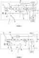
Figure 1 est un schéma d'une architecture de fonction de commande linéaire en courant pour un contrôleur de puissance à semi-conducteurs selon la présente invention ; - la
Figure 2 est un schéma d'une architecture de fonction de commande linéaire en tension pour un contrôleur de puissance à semi-conducteurs selon la présente invention ; - la
Figure 3 est un schéma synoptique d'une mise en œuvre matérielle d'une fonction de protection contre les courts-circuits pour un contrôleur de puissance à semi-conducteurs selon la présente invention ; et - la
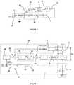
Figure 4 est un schéma synoptique d'une architecture de fonction de commande linéaire en température pour un contrôleur de puissance à semi-conducteurs selon la présente invention.
- the
Figure 1 is a diagram of a linear current control function architecture for a semiconductor power controller according to the present invention; - the
Figure 2 is a diagram of a linear voltage control function architecture for a semiconductor power controller according to the present invention; - the
Figure 3 is a block diagram of a hardware implementation of a protection function against shorts for a semiconductor power controller according to the present invention; and - the
Figure 4 is a block diagram of a linear temperature control function architecture for a semiconductor power controller according to the present invention.
En préambule technique à cette description détaillée, on peut mentionner pour mémoire qu'un contrôleur de puissance à semi-conducteurs comprend de manière schématique une partie puissance, comprenant des composants électroniques de puissance de commutation commandés par une partie commande pilotant les composants électroniques de puissance servant à la commutation. La charge est connectée aux bornes de la partie puissance, qui peut comprendre un ou plusieurs composants électroniques de puissance, l'invention n'étant pas limitée à cet égard et pouvant être appliquée à tout type de contrôleur de puissance à semi-conducteurs.As a technical preamble to this detailed description, it may be mentioned for the record that a semiconductor power controller schematically comprises a power part, comprising switching power electronic components controlled by a control part controlling the power electronic components. used for switching. The load is connected to the terminals of the power part, which can comprise one or more electronic power components, the invention not being limited in this regard and being able to be applied to any type of semiconductor power controller.
La partie commande peut comprendre divers éléments en fonction du type de contrôleur de puissance à semi-conducteurs (SSPC), mais les commandes d'asservissement sont réalisées d'une façon préférée par des circuits électroniques assurant un traitement analogique des différents signaux. Un traitement numérique des signaux serait bien entendu possible mais plus coûteux.The control part may include various elements depending on the type of semiconductor power controller (SSPC), but the servo controls are preferably performed by electronic circuits providing analog processing of the different signals. Digital signal processing would of course be possible but more expensive.
En outre, la partie commande comprend des câblages et des dispositifs de mesure, notamment du courant et de la tension au sein du contrôleur de puissance à semi-conducteurs.In addition, the control part includes wiring and measuring devices, including current and voltage within the semiconductor power controller.
Si l'on se réfère à la
On entend par commande linéaire une commande d'asservissement par un moyen de correction qui est régi par un système d'équations différentielles linéaires. C'est-à-dire des équations différentielles qui ont une forme linéaire par rapport à la variable d'état sur laquelle est basé l'asservissement et ses dérivées successives (ici le courant).By linear control is meant a servo control by a correction means which is governed by a system of linear differential equations. That is to say, differential equations which have a linear form with respect to the state variable on which the servo-control and its successive derivatives (here the current) are based.
La commande qui est décrite ici est assurée sur une seule ligne de courant 2, celle conduisant du pôle positif HVDC+ de la source à la charge 3.The control which is described here is ensured on a single
Il est bien entendu possible de prévoir un autre dispositif de commande linéaire d'un autre contacteur MOSFET (non représenté sur la figure) qui sera disposé entre le pôle négatif HVDC- de la source et la charge 3. Une telle solution sera particulièrement intéressante pour assurer un fonctionnement bidirectionnel du dispositif.It is of course possible to provide another linear control device for another MOSFET contactor (not shown in the figure) which will be placed between the negative HVDC- pole of the source and the
La commande linéaire en courant comprend un correcteur de courant Ci(p), un gain de mesure de courant Ki(p) circulant dans la partie puissance, un comparateur de courant 4, et une consigne de courant 5 qui est générée dans le SSPC, le correcteur de courant Ci(p) étant isolé de la partie commande par une isolation galvanique 6b.The linear current control comprises a current corrector Ci (p), a current measurement gain Ki (p) circulating in the power part, a
La consigne de courant est engendrée par un organe réglable (potentiomètre).The current setpoint is generated by an adjustable device (potentiometer).
L'isolation galvanique pourra être assurée par un coupleur optique.Galvanic isolation can be provided by an optical coupler.
Des capteurs de courant 7, présents dans le SSPC, mesurent le courant circulant dans les composants électroniques de puissance de la partie commande (donc ici dans le ou les composants électroniques de puissance MOSFET). Ces capteurs sont des composants classiques ou des miroirs de courant implantés directement dans le canal du MOSFET.
Le courant mesuré par le capteur 7 est envoyé au gain de mesure de courant Ki (p), au besoin par l'intermédiaire d'une isolation galvanique 6a en fonction du capteur, et ce courant mesuré est comparé par l'intermédiaire du comparateur 4 à une valeur de consigne 5. Le correcteur de courant Ci(p) corrige la valeur du courant en fonction de la précédente comparaison, de manière classique, par exemple par un correcteur proportionnel, Intégral et/ou dérivé, dans la boucle de commande et envoie au circuit de commande 8 du contacteur de puissance MOSFET une consigne de courant sous forme d'une tension de grille faisant évoluer la largeur du canal.The current measured by the
Ainsi, on peut fixer un courant de consigne qui constituera le courant d'appel maximal et, au moyen du correcteur de courant Ci (p), on met en œuvre une commande analogique permettant de limiter le courant d'appel lors de la mise sous tension de la charge capacitive en sortie du SSPC. Les composants électroniques mis en œuvre tant pour le comparateur 4 que pour le correcteur de courant sont des composants classiques dans le domaine de la régulation électronique (amplificateurs opérationnels, résistances, capacités). Il serait bien entendu possible mais plus coûteux de réaliser le correcteur de courant Ci(p) sous la forme d'un microprocesseur incorporant un algorithme d'asservissement numérique.Thus, it is possible to set a reference current which will constitute the maximum inrush current and, by means of the current corrector Ci (p), an analog command is implemented making it possible to limit the inrush current when switching on. voltage of the capacitive load at the output of the SSPC. The electronic components used both for the
Selon une caractéristique essentielle de l'invention, la limitation du courant est donc assurée par la commande directe des MOSFET du contrôleur de puissance donc sans adjonction de composants de découpage complémentaires.According to an essential characteristic of the invention, the current limitation is therefore ensured by the direct control of the MOSFETs of the power controller. therefore without the addition of additional cutting components.
Le contrôleur de puissance 1 incorpore aussi un module de coupure 23 qui comprend un bloc horloge 24 (timer) disposant de trois entrées et de deux sorties. Ce module 23 permet de prendre en compte le début et la fin d'un cycle soft-start. L'entrée « start » permet de lancer le bloc horloge 24 ainsi que le début d'une phase soft start par changement de la valeur de consigne 5. La consigne appliquée aux circuits passe alors d'une valeur initiale Iref correspondant à un contrôleur de puissance 1 ouvert (Iref=0A) à une valeur Iref de consigne non nulle correspondant à un contrôleur de puissance 1 fermé.The
Cette valeur de référence est bien évidemment choisie cohérente avec les limitations imposées par les normes du réseau électrique sur lequel le contrôleur 1 est utilisé, et avec les limitations intrinsèques du contrôleur 1 (limitations thermiques en particulier).This reference value is obviously chosen to be consistent with the limitations imposed by the standards of the electrical network on which the
La sortie « OFF » du bloc horloge 24 est alors inhibée et le circuit de commande 8 peut fonctionner.The “OFF” output of the
L'activation de l'entrée « Stop » du bloc horloge 24 permet d'arrêter ce dernier. Cette commande est activée par exemple lorsque le fonctionnement du contrôleur de puissance s'est correctement déroulé avant la fin du délai maximum donné par l'horloge (time-out). Les deux sorties du bloc horloge 24 ne sont pas activées par cette entrée « Stop ».Activation of the "Stop" input of
L'activation de l'entrée « Reset » du bloc horloge 24 permet de remettre le compteur du bloc horloge à zéro. Les deux sorties du bloc horloge 24 ne sont pas activées par cette entrée.Activation of the "Reset" input of
Une fois le bloc horloge 24 activé par « Start », si aucune des deux autres entrées (« reset » ou « stop ») n'est activée, ce qui signifie que le contrôleur de puissance n'a pas pu se fermer au bout du délai donné par le bloc horloge 24, un ordre d'ouverture du contrôleur de puissance 1 est envoyé par l'intermédiaire d'un signal de commande « OFF » vers le circuit de commande 8.Once
Ainsi, le contrôleur de puissance 1 s'arrête et le MOSFET s'ouvre.Thus, the
Une porte logique 25 de type OU a été ajoutée pour prendre en compte aussi bien les ordres « OFF » venant du bloc horloge 24 que ceux venant d'autres fonctions de protection (par exemple des protections thermiques décrites par la suite), ou des commandes d'ouverture normale pour arrêt du contrôleur 1.An OR-
Si l'on se réfère à la
Selon ce mode de réalisation, la partie commande du contrôleur de puissance 1 réalise une mesure de la tension aux bornes des composants électroniques de puissance de la partie puissance, en particulier la tension drain source VDS lorsque les composants électroniques de puissance sont des MOSFET. Un gain Kv(p) est appliqué à la mesure réalisée. Le contrôleur 1 comprend aussi un correcteur de tension Cv(p), un générateur de consigne de tension 9 et un comparateur 10 de la tension mesurée (affectée du gain Kv(p)) avec la tension de consigne.According to this embodiment, the control part of the
La consigne de tension est engendrée par un organe réglable (potentiomètre).The voltage setpoint is generated by an adjustable device (potentiometer).
Le correcteur de tension Cv(p) corrige la valeur de la tension en fonction de la précédente comparaison, de manière classique, par exemple par un correcteur proportionnel, Intégral et/ou dérivé, dans la boucle de commande et envoie au circuit de commande 8 du contacteur de puissance MOSFET une consigne de tension.The voltage corrector Cv (p) corrects the value of the voltage as a function of the previous comparison, in a conventional manner, for example by a corrector proportional, integral and / or derivative, in the control loop and sends a voltage reference to the
On notera qu'ici la consigne 9 est une valeur de tension optimale qui a été définie de telle sorte que le courant circulant dans le MOSFET soit optimisé. Le correcteur de tension Cv(p) agira de façon à commander le contacteur MOSFET pour approcher la valeur de consigne en tension. Ceci est obtenu par modulation de la largeur du canal du MOSFET.It will be noted that here
Là encore, le contrôleur de puissance 1 incorpore un module de coupure 23 tel que décrit précédemment.Here again, the
Si l'on se réfère à la
Ce circuit de protection peut être associé à l'un ou l'autre des circuits précédents.This protection circuit can be associated with one or other of the preceding circuits.
Le mode de réalisation représenté repose sur la mise en œuvre matérielle dans le SSPC de circuits RC qui permettent de modéliser l'échauffement thermique du ou des composants électroniques de puissance de la partie puissance. Les circuits de modélisation thermique des composants électroniques de puissance sont bien connus. On pourra mettre en œuvre un modèle thermique de Cauer ou un modèle thermique de Foster.The embodiment shown is based on the hardware implementation in the SSPC of RC circuits which make it possible to model the thermal heating of the power electronic component (s) of the power part. The circuits for thermal modeling of power electronic components are well known. We can implement a thermal model of Cauer or a thermal model of Foster.
La
Dans ce mode de réalisation, on mesure la tension VDS entre drain et Source du MOSFET 12 par l'amplificateur 13 (tension aux bornes du composant électronique de puissance). On mesure par ailleurs le courant I de la partie puissance (courant circulant dans le composant électronique de puissance) par un capteur de courant 7, le signal mesuré étant affecté d'un gain G1. On calcule au niveau d'un circuit multiplicateur 14 le produit des valeurs mesurées de la tension drain source et du courant. Ce produit affecté d'un gain G est une image de la puissance électrique instantanée dissipée dans le MOSFET 12. Le signal I=GVp de cette puissance est appliqué au circuit 11 qui est un modèle thermique du ou des composants de puissance. La tension VTj qui est mesurée à la sortie du circuit 11 est une image de la température du MOSFET 12. Elle est comparée (comparateur 15) à une valeur de référence Vref fournie par un circuit 16 approprié. La valeur de référence correspond à une température de seuil à partir de laquelle le MOSFET doit être ouvert (de l'ordre de 120 °C).In this embodiment, the voltage VDS is measured between the drain and the source of the
En fonction de l'élévation de température instantanée déterminée à l'étape précédente et du résultat de sa comparaison à une valeur de température seuil prédéterminée, on ouvre ou non le commutateur MOSFET 12 en agissant sur la tension de grille via le circuit de commande 8.Depending on the instantaneous temperature rise determined in the previous step and the result of its comparison with a predetermined threshold temperature value, the
Bien que seule la mise en œuvre matérielle soit décrite sur les Figures, une mise en œuvre logicielle des modèles thermiques des composants électroniques de puissance est tout à fait envisageable sur des SSPC intégrant une unité de calcul numérique, et entre dans le cadre de la présente invention, celle-ci n'étant aucunement limitée à une mise en œuvre matérielle des modèles thermiques des composants électroniques de puissance.Although only the hardware implementation is described in the Figures, a software implementation of the thermal models of the power electronic components is quite possible on SSPCs integrating a digital calculation unit, and falls within the scope of the present document. invention, which is in no way limited to a hardware implementation of thermal models of power electronic components.
La
A cet effet le contrôleur de puissance 1 comprend à la fois un module de mesure d'une tension de référence (tension drain source VDS du ou des MOSFET, donc tension aux bornes du ou des composants électroniques de puissance MOSFET) dans la partie puissance et un module de mesure d'un courant circulant dans la partie puissance (courant circulant dans le ou les composants électroniques de puissance).To this end, the
Comme dans le mode de réalisation selon la
Pour limiter l'intensité du courant, on applique l'intensité ainsi corrigée au sommateur 17 qui est suivi d'un correcteur de courant Ci(p) qui assure l'écrêtage de l'intensité et assurera une coupure du MOSFET via le circuit de commande 8 en cas de surintensité.To limit the intensity of the current, the intensity thus corrected is applied to the
Parallèlement, l'intensité mesurée et corrigée Ki(p) est appliquée à un circuit de modélisation thermique 11 (modèle de Cauer ou de Foster) avec la mesure corrigée de la tension drain source Kv(p). La sortie 18 du circuit de modélisation thermique 11 (ou module d'estimation de la température des composants de puissance) donne une tension qui est une image de la température du MOSFET. Cette sortie est appliquée à un comparateur 19 dans lequel elle est comparée à une valeur de consigne Tj0 fournie par un module de génération de consigne de température 20 (qui est réalisé sous la forme d'un circuit électronique).At the same time, the measured and corrected intensity Ki (p) is applied to a thermal modeling circuit 11 (Cauer or Foster model) with the corrected measurement of the drain source voltage Kv (p). The
Le résultat de la comparaison est appliqué à un module de correction de température 21 qui incorpore un correcteur de température CT(p) qui va fournir un signal correspondant à une tension ou une intensité de référence qui sera ensuite appliquée au circuit de commande 8 au travers du sommateur 17.The result of the comparison is applied to a
Le module de correction de température 21 incorpore aussi un module 22 assurant le bornage de la consigne de commande.The
Le contrôleur de puissance 1 comprendra également un module de coupure 23 tel que décrit précédemment.The
L'invention a été décrite dans ses trois modes de réalisation appliquée à l'ouverture d'un seul MOSFET disposé sur une ligne de courant 2 entre le pôle positif HVDC+ de la source et la charge 3.The invention has been described in its three embodiments applied to the opening of a single MOSFET arranged on a
Il est bien entendu possible de doubler les moyens de commande et d'asservissement pour commander aussi l'ouverture d'un autre MOSFET interposé entre le pôle négatif HVDC- de la source et la charge 3. Une telle disposition permettra d'assurer le caractère bidirectionnel de la commande du contrôleur de puissance.It is of course possible to double the control and slaving means to also control the opening of another MOSFET interposed between the negative HVDC- pole of the source and the
Claims (14)
- A solid-state power controller, abbreviated SSPC (1), comprising a power portion with a base of one or several electronic power components, and a control portion comprising at least one signal processing device and controlling the operation of the power portion,characterized in that the signal processing device executes a linear control function of the power portion in order to limit the inrush current when applying voltage to a load (3) on a DC network by means of the solid-state power controller (1), the controller incorporating means ensuring the measurement of the current circulating in the electronic power component(s) and/or the voltage across the terminals of the electronic power components, as well as a module making it possible to provide a current setpoint (5), or voltage setpoint (9), or temperature setpoint (20) and a module ensuring, as a function of the deviation between the measurement and the setpoint, a current or voltage or temperature correction which is applied to a control circuit (8) of the power portion of the controller.
- The solid-state power controller (1) according to claim 1,characterized in that the linear control function ensures control by current regulation of the electronic power component(s).
- The solid-state power controller (1) according to claim 2,characterized in that the linear control function by current regulation comprises a current detection module (7) detecting current circulating in the power portion, a current setpoint generating module (5), a comparison module (4) comparing the current setpoint and the current circulating in the power portion, a current correction module (Ci(p)), correcting the value of the current sent into the power portion as a function of the result of the comparison by the comparison module (4).
- The solid-state power controller (1) according to claim 1,characterized in that the linear control function ensures control by voltage regulation of the electronic power component(s).
- The solid-state power controller (1) according to claim 4,characterized in that the linear control function by voltage regulation comprises a module for measuring a reference voltage in the power portion, a voltage setpoint generating module (9), a comparison module (10) comparing the voltage setpoint and the reference voltage measured in the power portion, a voltage correction module (Cv(p)), correcting the value of the reference voltage in the power portion as a function of the result of the comparison by the comparison module (10).
- The solid-state power controller (1) according to one of claims 1 to 5,characterized in that it comprises a module for protecting against short-circuits.
- The solid-state power controller (1) according to claim 6,characterized in that the module protecting against short-circuits comprises a module for detecting the temperature of the electronic power component(s) (12) of the power portion, triggering a circuit for protecting the power portion when the measured temperature is above a reference temperature value.
- The solid-state power controller (1) according to claim 7,characterized in that the module for detecting the temperature of the electronic power component(s) comprises a current measuring module (7), a voltage measuring module (13) and a thermal modeling module (11) of the electronic power component(s) yielding a temperature increase value for a measured voltage and current.
- The solid-state power controller (1) according to claim 8,characterized in that the thermal modeling module (11) uses a Foster model or a Cauer model for the electronic power component thermal model (12), this model being done in the form of a network of capacitors (C) and resistances (R).
- The solid-state power controller (1) according to claim 1,characterized in that the linear control function ensures control by temperature regulation of the electronic power component(s).
- The solid-state power controller according to claim 10,characterized in that the linear control function by temperature regulation comprises a module for measuring a reference voltage in the power portion, a module for measuring a current (7) circulating in the power portion, a module for generating a temperature setpoint (20), a module for estimating the temperature (11) of the power components, a comparison module (19) comparing the estimated temperature and a setpoint temperature, a temperature correction module (21) ensuring a correction of the voltage and/or of the reference intensity in the power portion as a function of the result of the comparison by the comparison module (19).
- The solid-state power controller (1) according to claim 11,characterized in that the module for estimating the temperature (11) of the power component(s) uses a Foster model or a Cauer model for the electronic power component thermal model, this model being done in the form of a network of capacitors (C) and resistances (R).
- The solid-state power controller (1) according to claim 12,characterized in that it comprises a module for limiting the value of the current in the power portion.
- The solid-state power controller (1) according to one of claims 1 to 13,characterized in that it comprises a cutoff module making it possible to interrupt the operation beyond a certain operating time in pre-load mode.
Applications Claiming Priority (2)
| Application Number | Priority Date | Filing Date | Title |
|---|---|---|---|
| FR1303084AFR3016090B1 (en) | 2013-12-26 | 2013-12-26 | POWER CONTROLLER WITH LINEAR CURRENT LIMITATION CONTROL AND SHORT CIRCUIT PROTECTION |
| PCT/FR2014/053506WO2015097394A1 (en) | 2013-12-26 | 2014-12-22 | Power controller with linear control of current peak limitation and with short-circuit protection |
Publications (2)
| Publication Number | Publication Date |
|---|---|
| EP3087647A1 EP3087647A1 (en) | 2016-11-02 |
| EP3087647B1true EP3087647B1 (en) | 2021-04-28 |
Family
ID=50639587
Family Applications (1)
| Application Number | Title | Priority Date | Filing Date |
|---|---|---|---|
| EP14830847.1AActiveEP3087647B1 (en) | 2013-12-26 | 2014-12-22 | Power controller with linear control of current peak limitation and with short-circuit protection |
Country Status (3)
| Country | Link |
|---|---|
| EP (1) | EP3087647B1 (en) |
| FR (1) | FR3016090B1 (en) |
| WO (1) | WO2015097394A1 (en) |
Families Citing this family (4)
| Publication number | Priority date | Publication date | Assignee | Title |
|---|---|---|---|---|
| FR3065589B1 (en)* | 2017-04-25 | 2020-02-14 | Airbus Operations | LIGHTNING AND SHORT-CIRCUIT PROTECTION SYSTEM FOR ELECTRICAL EQUIPMENT ON BOARD AN AIRCRAFT |
| EP3402072B1 (en) | 2017-05-08 | 2021-06-30 | Hamilton Sundstrand Corporation | Inrush current limiting system and method |
| US11977131B2 (en) | 2020-11-18 | 2024-05-07 | Rolls-Royce North American Technologies, Inc. | Fault detection for a solid state power converter |
| US11588322B2 (en) | 2020-11-20 | 2023-02-21 | Rolls-Royce North American Technologies, Inc. | Fault detection for a solid state power converter |
Family Cites Families (3)
| Publication number | Priority date | Publication date | Assignee | Title |
|---|---|---|---|---|
| US7019583B2 (en)* | 2001-01-29 | 2006-03-28 | Axiohm Transaction Solutions, Inc. | Current inrush limiting circuit |
| KR101361606B1 (en)* | 2007-07-30 | 2014-02-12 | 삼성전자주식회사 | Method and Device of Reducing an Inrush Current in an Initial Unstable State |
| US8716997B2 (en) | 2010-06-16 | 2014-05-06 | Honeywell International, Inc. | High power DC SSPC with capability of soft turn-on large capacitive loads |
- 2013
- 2013-12-26FRFR1303084Apatent/FR3016090B1/enactiveActive
- 2014
- 2014-12-22WOPCT/FR2014/053506patent/WO2015097394A1/enactiveApplication Filing
- 2014-12-22EPEP14830847.1Apatent/EP3087647B1/enactiveActive
Non-Patent Citations (1)
| Title |
|---|
| None* |
Also Published As
| Publication number | Publication date |
|---|---|
| FR3016090B1 (en) | 2017-05-12 |
| WO2015097394A1 (en) | 2015-07-02 |
| EP3087647A1 (en) | 2016-11-02 |
| FR3016090A1 (en) | 2015-07-03 |
Similar Documents
| Publication | Publication Date | Title |
|---|---|---|
| EP1977514B1 (en) | Controlling a mos transistor | |
| EP3087647B1 (en) | Power controller with linear control of current peak limitation and with short-circuit protection | |
| FR2957466A1 (en) | SSPC WITH ACTIVE CURRENT LIMITATION. | |
| FR2962270A1 (en) | IMPROVED ELECTRICAL ROTATING MACHINE TO PROVIDE PROTECTION AGAINST POWER SUPPLY BREAKS | |
| FR3002050A1 (en) | THERMAL REGULATOR | |
| WO2016170262A1 (en) | Voltage regulator of a motor vehicle alternator, regulator brush holder and corresponding alternators | |
| EP0782265B1 (en) | Method and device for protecting an adjustable impedance element controlling the supply of an electric motor, particularly of a motor vehicle | |
| EP1992069B1 (en) | Device for controlling a mos transistor | |
| EP3435505A1 (en) | Method for controlling trigger currents that can circulate in a load switch, and corresponding electronic circuit | |
| FR3030152A1 (en) | METHOD FOR CONTROLLING A DEVICE FOR CONTROLLING A MOTOR VEHICLE ALTERNATOR, CORRESPONDING REGULATION DEVICE AND ALTERNATOR | |
| WO2020011781A1 (en) | Method for controlling a module for controlling a transistor | |
| FR2826801A1 (en) | VEHICLE GENERATOR CONTROL SYSTEM | |
| EP3028356A1 (en) | System for managing a supply voltage of an onboard electrical network of a motor vehicle | |
| EP2093868B1 (en) | Device and control circuit of an electronic power component, associated control method and distributor | |
| JP5097229B2 (en) | Overheat protection device | |
| FR3068836B1 (en) | PROTECTIVE CIRCUIT FOR A POWER SWITCH | |
| EP3794700B1 (en) | Circuit for protecting a switch | |
| EP3369178A1 (en) | Control device for transistors | |
| FR3057406A1 (en) | DISCHARGE CIRCUIT FOR A HIGH VOLTAGE ELECTRICAL SYSTEM | |
| EP3020109A1 (en) | System for stabilising a supply voltage of an on-board electrical system of a motor vehicle | |
| WO2023089248A1 (en) | Method for overvoltage protection in a system comprising a battery, an inverter and an electrical machine | |
| EP3127212B1 (en) | System for stabilizing a supply voltage of an onboard electrical network of an automotive vehicle | |
| FR3083933A1 (en) | METHOD FOR REDUCING ELECTROMAGNETIC DISTURBANCES PRODUCED DURING THE PASSING UP OF A TRANSISTOR | |
| EP3051647A1 (en) | System for stabilising a supply voltage of an on-board electrical network of a motor vehicle |
Legal Events
| Date | Code | Title | Description |
|---|---|---|---|
| PUAI | Public reference made under article 153(3) epc to a published international application that has entered the european phase | Free format text:ORIGINAL CODE: 0009012 | |
| 17P | Request for examination filed | Effective date:20160707 | |
| AK | Designated contracting states | Kind code of ref document:A1 Designated state(s):AL AT BE BG CH CY CZ DE DK EE ES FI FR GB GR HR HU IE IS IT LI LT LU LV MC MK MT NL NO PL PT RO RS SE SI SK SM TR | |
| AX | Request for extension of the european patent | Extension state:BA ME | |
| DAX | Request for extension of the european patent (deleted) | ||
| STAA | Information on the status of an ep patent application or granted ep patent | Free format text:STATUS: EXAMINATION IS IN PROGRESS | |
| 17Q | First examination report despatched | Effective date:20181001 | |
| RAP1 | Party data changed (applicant data changed or rights of an application transferred) | Owner name:NEXTER SYSTEMS | |
| GRAP | Despatch of communication of intention to grant a patent | Free format text:ORIGINAL CODE: EPIDOSNIGR1 | |
| STAA | Information on the status of an ep patent application or granted ep patent | Free format text:STATUS: GRANT OF PATENT IS INTENDED | |
| INTG | Intention to grant announced | Effective date:20201127 | |
| RAP1 | Party data changed (applicant data changed or rights of an application transferred) | Owner name:NEXTER SYSTEMS | |
| GRAS | Grant fee paid | Free format text:ORIGINAL CODE: EPIDOSNIGR3 | |
| GRAA | (expected) grant | Free format text:ORIGINAL CODE: 0009210 | |
| STAA | Information on the status of an ep patent application or granted ep patent | Free format text:STATUS: THE PATENT HAS BEEN GRANTED | |
| AK | Designated contracting states | Kind code of ref document:B1 Designated state(s):AL AT BE BG CH CY CZ DE DK EE ES FI FR GB GR HR HU IE IS IT LI LT LU LV MC MK MT NL NO PL PT RO RS SE SI SK SM TR | |
| REG | Reference to a national code | Ref country code:GB Ref legal event code:FG4D Free format text:NOT ENGLISH | |
| REG | Reference to a national code | Ref country code:CH Ref legal event code:EP | |
| REG | Reference to a national code | Ref country code:DE Ref legal event code:R096 Ref document number:602014077047 Country of ref document:DE | |
| REG | Reference to a national code | Ref country code:AT Ref legal event code:REF Ref document number:1388213 Country of ref document:AT Kind code of ref document:T Effective date:20210515 | |
| REG | Reference to a national code | Ref country code:IE Ref legal event code:FG4D Free format text:LANGUAGE OF EP DOCUMENT: FRENCH | |
| REG | Reference to a national code | Ref country code:NL Ref legal event code:FP | |
| REG | Reference to a national code | Ref country code:LT Ref legal event code:MG9D | |
| REG | Reference to a national code | Ref country code:AT Ref legal event code:MK05 Ref document number:1388213 Country of ref document:AT Kind code of ref document:T Effective date:20210428 | |
| PG25 | Lapsed in a contracting state [announced via postgrant information from national office to epo] | Ref country code:AT Free format text:LAPSE BECAUSE OF FAILURE TO SUBMIT A TRANSLATION OF THE DESCRIPTION OR TO PAY THE FEE WITHIN THE PRESCRIBED TIME-LIMIT Effective date:20210428 Ref country code:BG Free format text:LAPSE BECAUSE OF FAILURE TO SUBMIT A TRANSLATION OF THE DESCRIPTION OR TO PAY THE FEE WITHIN THE PRESCRIBED TIME-LIMIT Effective date:20210728 Ref country code:FI Free format text:LAPSE BECAUSE OF FAILURE TO SUBMIT A TRANSLATION OF THE DESCRIPTION OR TO PAY THE FEE WITHIN THE PRESCRIBED TIME-LIMIT Effective date:20210428 Ref country code:LT Free format text:LAPSE BECAUSE OF FAILURE TO SUBMIT A TRANSLATION OF THE DESCRIPTION OR TO PAY THE FEE WITHIN THE PRESCRIBED TIME-LIMIT Effective date:20210428 Ref country code:HR Free format text:LAPSE BECAUSE OF FAILURE TO SUBMIT A TRANSLATION OF THE DESCRIPTION OR TO PAY THE FEE WITHIN THE PRESCRIBED TIME-LIMIT Effective date:20210428 | |
| PG25 | Lapsed in a contracting state [announced via postgrant information from national office to epo] | Ref country code:GR Free format text:LAPSE BECAUSE OF FAILURE TO SUBMIT A TRANSLATION OF THE DESCRIPTION OR TO PAY THE FEE WITHIN THE PRESCRIBED TIME-LIMIT Effective date:20210729 Ref country code:IS Free format text:LAPSE BECAUSE OF FAILURE TO SUBMIT A TRANSLATION OF THE DESCRIPTION OR TO PAY THE FEE WITHIN THE PRESCRIBED TIME-LIMIT Effective date:20210828 Ref country code:LV Free format text:LAPSE BECAUSE OF FAILURE TO SUBMIT A TRANSLATION OF THE DESCRIPTION OR TO PAY THE FEE WITHIN THE PRESCRIBED TIME-LIMIT Effective date:20210428 Ref country code:SE Free format text:LAPSE BECAUSE OF FAILURE TO SUBMIT A TRANSLATION OF THE DESCRIPTION OR TO PAY THE FEE WITHIN THE PRESCRIBED TIME-LIMIT Effective date:20210428 Ref country code:RS Free format text:LAPSE BECAUSE OF FAILURE TO SUBMIT A TRANSLATION OF THE DESCRIPTION OR TO PAY THE FEE WITHIN THE PRESCRIBED TIME-LIMIT Effective date:20210428 Ref country code:PT Free format text:LAPSE BECAUSE OF FAILURE TO SUBMIT A TRANSLATION OF THE DESCRIPTION OR TO PAY THE FEE WITHIN THE PRESCRIBED TIME-LIMIT Effective date:20210830 Ref country code:NO Free format text:LAPSE BECAUSE OF FAILURE TO SUBMIT A TRANSLATION OF THE DESCRIPTION OR TO PAY THE FEE WITHIN THE PRESCRIBED TIME-LIMIT Effective date:20210728 Ref country code:PL Free format text:LAPSE BECAUSE OF FAILURE TO SUBMIT A TRANSLATION OF THE DESCRIPTION OR TO PAY THE FEE WITHIN THE PRESCRIBED TIME-LIMIT Effective date:20210428 Ref country code:ES Free format text:LAPSE BECAUSE OF FAILURE TO SUBMIT A TRANSLATION OF THE DESCRIPTION OR TO PAY THE FEE WITHIN THE PRESCRIBED TIME-LIMIT Effective date:20210428 | |
| PG25 | Lapsed in a contracting state [announced via postgrant information from national office to epo] | Ref country code:SK Free format text:LAPSE BECAUSE OF FAILURE TO SUBMIT A TRANSLATION OF THE DESCRIPTION OR TO PAY THE FEE WITHIN THE PRESCRIBED TIME-LIMIT Effective date:20210428 Ref country code:SM Free format text:LAPSE BECAUSE OF FAILURE TO SUBMIT A TRANSLATION OF THE DESCRIPTION OR TO PAY THE FEE WITHIN THE PRESCRIBED TIME-LIMIT Effective date:20210428 Ref country code:EE Free format text:LAPSE BECAUSE OF FAILURE TO SUBMIT A TRANSLATION OF THE DESCRIPTION OR TO PAY THE FEE WITHIN THE PRESCRIBED TIME-LIMIT Effective date:20210428 Ref country code:DK Free format text:LAPSE BECAUSE OF FAILURE TO SUBMIT A TRANSLATION OF THE DESCRIPTION OR TO PAY THE FEE WITHIN THE PRESCRIBED TIME-LIMIT Effective date:20210428 Ref country code:CZ Free format text:LAPSE BECAUSE OF FAILURE TO SUBMIT A TRANSLATION OF THE DESCRIPTION OR TO PAY THE FEE WITHIN THE PRESCRIBED TIME-LIMIT Effective date:20210428 Ref country code:RO Free format text:LAPSE BECAUSE OF FAILURE TO SUBMIT A TRANSLATION OF THE DESCRIPTION OR TO PAY THE FEE WITHIN THE PRESCRIBED TIME-LIMIT Effective date:20210428 | |
| REG | Reference to a national code | Ref country code:DE Ref legal event code:R097 Ref document number:602014077047 Country of ref document:DE | |
| PLBE | No opposition filed within time limit | Free format text:ORIGINAL CODE: 0009261 | |
| STAA | Information on the status of an ep patent application or granted ep patent | Free format text:STATUS: NO OPPOSITION FILED WITHIN TIME LIMIT | |
| 26N | No opposition filed | Effective date:20220131 | |
| PG25 | Lapsed in a contracting state [announced via postgrant information from national office to epo] | Ref country code:IS Free format text:LAPSE BECAUSE OF FAILURE TO SUBMIT A TRANSLATION OF THE DESCRIPTION OR TO PAY THE FEE WITHIN THE PRESCRIBED TIME-LIMIT Effective date:20210828 Ref country code:AL Free format text:LAPSE BECAUSE OF FAILURE TO SUBMIT A TRANSLATION OF THE DESCRIPTION OR TO PAY THE FEE WITHIN THE PRESCRIBED TIME-LIMIT Effective date:20210428 | |
| PG25 | Lapsed in a contracting state [announced via postgrant information from national office to epo] | Ref country code:MC Free format text:LAPSE BECAUSE OF FAILURE TO SUBMIT A TRANSLATION OF THE DESCRIPTION OR TO PAY THE FEE WITHIN THE PRESCRIBED TIME-LIMIT Effective date:20210428 Ref country code:IT Free format text:LAPSE BECAUSE OF FAILURE TO SUBMIT A TRANSLATION OF THE DESCRIPTION OR TO PAY THE FEE WITHIN THE PRESCRIBED TIME-LIMIT Effective date:20210428 | |
| REG | Reference to a national code | Ref country code:CH Ref legal event code:PL | |
| REG | Reference to a national code | Ref country code:BE Ref legal event code:MM Effective date:20211231 | |
| PG25 | Lapsed in a contracting state [announced via postgrant information from national office to epo] | Ref country code:LU Free format text:LAPSE BECAUSE OF NON-PAYMENT OF DUE FEES Effective date:20211222 Ref country code:IE Free format text:LAPSE BECAUSE OF NON-PAYMENT OF DUE FEES Effective date:20211222 | |
| PG25 | Lapsed in a contracting state [announced via postgrant information from national office to epo] | Ref country code:BE Free format text:LAPSE BECAUSE OF NON-PAYMENT OF DUE FEES Effective date:20211231 | |
| PG25 | Lapsed in a contracting state [announced via postgrant information from national office to epo] | Ref country code:LI Free format text:LAPSE BECAUSE OF NON-PAYMENT OF DUE FEES Effective date:20211231 Ref country code:CH Free format text:LAPSE BECAUSE OF NON-PAYMENT OF DUE FEES Effective date:20211231 | |
| PG25 | Lapsed in a contracting state [announced via postgrant information from national office to epo] | Ref country code:HU Free format text:LAPSE BECAUSE OF FAILURE TO SUBMIT A TRANSLATION OF THE DESCRIPTION OR TO PAY THE FEE WITHIN THE PRESCRIBED TIME-LIMIT; INVALID AB INITIO Effective date:20141222 | |
| PG25 | Lapsed in a contracting state [announced via postgrant information from national office to epo] | Ref country code:CY Free format text:LAPSE BECAUSE OF FAILURE TO SUBMIT A TRANSLATION OF THE DESCRIPTION OR TO PAY THE FEE WITHIN THE PRESCRIBED TIME-LIMIT Effective date:20210428 | |
| PG25 | Lapsed in a contracting state [announced via postgrant information from national office to epo] | Ref country code:MK Free format text:LAPSE BECAUSE OF FAILURE TO SUBMIT A TRANSLATION OF THE DESCRIPTION OR TO PAY THE FEE WITHIN THE PRESCRIBED TIME-LIMIT Effective date:20210428 | |
| PG25 | Lapsed in a contracting state [announced via postgrant information from national office to epo] | Ref country code:TR Free format text:LAPSE BECAUSE OF FAILURE TO SUBMIT A TRANSLATION OF THE DESCRIPTION OR TO PAY THE FEE WITHIN THE PRESCRIBED TIME-LIMIT Effective date:20210428 | |
| PG25 | Lapsed in a contracting state [announced via postgrant information from national office to epo] | Ref country code:MT Free format text:LAPSE BECAUSE OF FAILURE TO SUBMIT A TRANSLATION OF THE DESCRIPTION OR TO PAY THE FEE WITHIN THE PRESCRIBED TIME-LIMIT Effective date:20210428 | |
| PGFP | Annual fee paid to national office [announced via postgrant information from national office to epo] | Ref country code:NL Payment date:20241121 Year of fee payment:11 | |
| PGFP | Annual fee paid to national office [announced via postgrant information from national office to epo] | Ref country code:DE Payment date:20241121 Year of fee payment:11 | |
| PGFP | Annual fee paid to national office [announced via postgrant information from national office to epo] | Ref country code:GB Payment date:20241122 Year of fee payment:11 | |
| PGFP | Annual fee paid to national office [announced via postgrant information from national office to epo] | Ref country code:FR Payment date:20241121 Year of fee payment:11 |