EP3086726B1 - Distal radius plate - Google Patents
Distal radius plateDownload PDFInfo
- Publication number
- EP3086726B1 EP3086726B1EP14824330.6AEP14824330AEP3086726B1EP 3086726 B1EP3086726 B1EP 3086726B1EP 14824330 AEP14824330 AEP 14824330AEP 3086726 B1EP3086726 B1EP 3086726B1
- Authority
- EP
- European Patent Office
- Prior art keywords
- bone
- elongate
- triangular
- plate body
- longitudinal axis
- Prior art date
- Legal status (The legal status is an assumption and is not a legal conclusion. Google has not performed a legal analysis and makes no representation as to the accuracy of the status listed.)
- Active
Links
Images


Classifications
- A—HUMAN NECESSITIES
- A61—MEDICAL OR VETERINARY SCIENCE; HYGIENE
- A61B—DIAGNOSIS; SURGERY; IDENTIFICATION
- A61B17/00—Surgical instruments, devices or methods
- A61B17/56—Surgical instruments or methods for treatment of bones or joints; Devices specially adapted therefor
- A61B17/58—Surgical instruments or methods for treatment of bones or joints; Devices specially adapted therefor for osteosynthesis, e.g. bone plates, screws or setting implements
- A61B17/68—Internal fixation devices, including fasteners and spinal fixators, even if a part thereof projects from the skin
- A61B17/80—Cortical plates, i.e. bone plates; Instruments for holding or positioning cortical plates, or for compressing bones attached to cortical plates
- A61B17/8052—Cortical plates, i.e. bone plates; Instruments for holding or positioning cortical plates, or for compressing bones attached to cortical plates immobilised relative to screws by interlocking form of the heads and plate holes, e.g. conical or threaded
- A61B17/8057—Cortical plates, i.e. bone plates; Instruments for holding or positioning cortical plates, or for compressing bones attached to cortical plates immobilised relative to screws by interlocking form of the heads and plate holes, e.g. conical or threaded the interlocking form comprising a thread
- A—HUMAN NECESSITIES
- A61—MEDICAL OR VETERINARY SCIENCE; HYGIENE
- A61B—DIAGNOSIS; SURGERY; IDENTIFICATION
- A61B17/00—Surgical instruments, devices or methods
- A61B17/56—Surgical instruments or methods for treatment of bones or joints; Devices specially adapted therefor
- A61B17/58—Surgical instruments or methods for treatment of bones or joints; Devices specially adapted therefor for osteosynthesis, e.g. bone plates, screws or setting implements
- A61B17/68—Internal fixation devices, including fasteners and spinal fixators, even if a part thereof projects from the skin
- A61B17/80—Cortical plates, i.e. bone plates; Instruments for holding or positioning cortical plates, or for compressing bones attached to cortical plates
- A61B17/8052—Cortical plates, i.e. bone plates; Instruments for holding or positioning cortical plates, or for compressing bones attached to cortical plates immobilised relative to screws by interlocking form of the heads and plate holes, e.g. conical or threaded
- A—HUMAN NECESSITIES
- A61—MEDICAL OR VETERINARY SCIENCE; HYGIENE
- A61B—DIAGNOSIS; SURGERY; IDENTIFICATION
- A61B17/00—Surgical instruments, devices or methods
- A61B17/56—Surgical instruments or methods for treatment of bones or joints; Devices specially adapted therefor
- A61B17/58—Surgical instruments or methods for treatment of bones or joints; Devices specially adapted therefor for osteosynthesis, e.g. bone plates, screws or setting implements
- A61B17/68—Internal fixation devices, including fasteners and spinal fixators, even if a part thereof projects from the skin
- A61B17/80—Cortical plates, i.e. bone plates; Instruments for holding or positioning cortical plates, or for compressing bones attached to cortical plates
- A61B17/8033—Cortical plates, i.e. bone plates; Instruments for holding or positioning cortical plates, or for compressing bones attached to cortical plates having indirect contact with screw heads, or having contact with screw heads maintained with the aid of additional components, e.g. nuts, wedges or head covers
- A61B17/8047—Cortical plates, i.e. bone plates; Instruments for holding or positioning cortical plates, or for compressing bones attached to cortical plates having indirect contact with screw heads, or having contact with screw heads maintained with the aid of additional components, e.g. nuts, wedges or head covers wherein the additional element surrounds the screw head in the plate hole
- A—HUMAN NECESSITIES
- A61—MEDICAL OR VETERINARY SCIENCE; HYGIENE
- A61B—DIAGNOSIS; SURGERY; IDENTIFICATION
- A61B17/00—Surgical instruments, devices or methods
- A61B17/56—Surgical instruments or methods for treatment of bones or joints; Devices specially adapted therefor
- A61B17/58—Surgical instruments or methods for treatment of bones or joints; Devices specially adapted therefor for osteosynthesis, e.g. bone plates, screws or setting implements
- A61B17/68—Internal fixation devices, including fasteners and spinal fixators, even if a part thereof projects from the skin
- A61B17/80—Cortical plates, i.e. bone plates; Instruments for holding or positioning cortical plates, or for compressing bones attached to cortical plates
- A61B17/8061—Cortical plates, i.e. bone plates; Instruments for holding or positioning cortical plates, or for compressing bones attached to cortical plates specially adapted for particular bones
- A—HUMAN NECESSITIES
- A61—MEDICAL OR VETERINARY SCIENCE; HYGIENE
- A61B—DIAGNOSIS; SURGERY; IDENTIFICATION
- A61B17/00—Surgical instruments, devices or methods
- A61B17/56—Surgical instruments or methods for treatment of bones or joints; Devices specially adapted therefor
- A61B17/58—Surgical instruments or methods for treatment of bones or joints; Devices specially adapted therefor for osteosynthesis, e.g. bone plates, screws or setting implements
- A61B17/68—Internal fixation devices, including fasteners and spinal fixators, even if a part thereof projects from the skin
- A61B17/80—Cortical plates, i.e. bone plates; Instruments for holding or positioning cortical plates, or for compressing bones attached to cortical plates
- A61B17/808—Instruments for holding or positioning bone plates, or for adjusting screw-to-plate locking mechanisms
- A—HUMAN NECESSITIES
- A61—MEDICAL OR VETERINARY SCIENCE; HYGIENE
- A61B—DIAGNOSIS; SURGERY; IDENTIFICATION
- A61B17/00—Surgical instruments, devices or methods
- A61B17/56—Surgical instruments or methods for treatment of bones or joints; Devices specially adapted therefor
- A61B17/58—Surgical instruments or methods for treatment of bones or joints; Devices specially adapted therefor for osteosynthesis, e.g. bone plates, screws or setting implements
- A61B17/68—Internal fixation devices, including fasteners and spinal fixators, even if a part thereof projects from the skin
- A61B17/84—Fasteners therefor or fasteners being internal fixation devices
- A61B17/86—Pins or screws or threaded wires; nuts therefor
- A61B17/8605—Heads, i.e. proximal ends projecting from bone
- A—HUMAN NECESSITIES
- A61—MEDICAL OR VETERINARY SCIENCE; HYGIENE
- A61B—DIAGNOSIS; SURGERY; IDENTIFICATION
- A61B17/00—Surgical instruments, devices or methods
- A61B17/56—Surgical instruments or methods for treatment of bones or joints; Devices specially adapted therefor
- A61B17/58—Surgical instruments or methods for treatment of bones or joints; Devices specially adapted therefor for osteosynthesis, e.g. bone plates, screws or setting implements
- A61B17/68—Internal fixation devices, including fasteners and spinal fixators, even if a part thereof projects from the skin
- A61B17/84—Fasteners therefor or fasteners being internal fixation devices
- A61B17/86—Pins or screws or threaded wires; nuts therefor
- A61B17/8625—Shanks, i.e. parts contacting bone tissue
Definitions
- the present inventionrelates generally to orthopedic plates, and more particularly but not exclusively relates to orthopedic distal radius plates.
- Bone plate fixation systems for repairing bone fracturesare commonly used in a variety of orthopedic applications. These fixation systems include bone plates that may be provided in many shapes, sizes and configurations. In cases where a bone is severely comminuted or if bone segments are missing, the use of a bone plate fixation system promotes healing of the fracture by providing a rigid fixation or support structure between the bone and the plate. In some instances, the bone plate fixation system is designed for use in treating a particular type of bone or a specific portion or region of a bone, and may also be provided with specific structures and / or features that facilitate treatment of the bone and provide the necessary support and stabilization to facilitate healing.
- US 2013172943 A1discloses the preamble of claim 1.
- a novel orthopedic bone platewhich presents a stable connection between the bone plate and the distal radius bone, and which includes structures and features that facilitate treatment of the bone to provide support and stabilization to facilitate healing.
- a bone plate fixation systemwhich includes a plurality of bone screws, each including a screw head and a threaded shank extending from the screw head and adapted for anchoring within bone, and a bone plate extending along a central longitudinal axis and having a plate body defining an outer perimeter that is substantially symmetrical relative to the longitudinal axis, the plate body including an elongate shaft portion and a triangular-shaped head portion extending from the elongate shaft portion.
- the plate bodyincludes a number of bone screw openings extending therethrough, each having an inner surface and a plurality of flexible fins integrally connected to and protruding radially inward from the inner surface.
- the plurality of flexible finsare deflectable by the screw head of one of the bone screws inserted into a corresponding one of the bone screw openings to retain the bone screw in position within the corresponding opening relative to the plate body.
- the elongate shaft portion of the plate bodyincludes a first plurality of the bone screw openings and an elongate slot having a slot length extending along the longitudinal axis.
- the triangular-shaped head portion of the plate bodyincludes a second plurality of the bone screw openings and at least one fastener opening extending therethrough that does not include the plurality of flexible fins.
- the triangular-shaped head portion of the plate bodyincludes a second elongate slot having a slot length extending generally parallel with the longitudinal axis.
- the triangular-shaped head portionfurther includes an elongate visualization window extending therethrough and having a window length extending in a direction transverse to the longitudinal axis of the plate body.
- the elongate visualization windowhas a trapezoidal shape.
- the elongate visualization windowis defined by a pair of substantially parallel bases extending along the window length, and a pair of non-parallel legs that extend substantially parallel with corresponding peripheral side surfaces defined by the triangular-shaped head portion of the plate body.
- the screw head of at least some of the plurality of bone screwsincludes an external thread adapted to engage with the plurality of flexible fins of a corresponding one of the bone screw openings.
- the plurality of flexible finsprovide each of the plurality of bone screw openings with a star-shaped configuration.
- the aperture length of the elongate aperture in the triangular-shaped head portionextends in a direction substantially parallel with the slot length of the elongate slot in the elongate shaft portion.
- the elongate slot in the elongate shaft portionis centered along the longitudinal axis and the elongate aperture in the triangular-shaped head portion is laterally offset from the longitudinal axis.
- the elongate slot in the elongate shaft portionhas a slot width and the elongate aperture in the triangular-shaped head portion has an aperture width that is less than the slot width.
- the bone plate fixation systemfarther includes a K-wire or pin positioned within and extending through the elongate aperture and adapted for anchoring in the bone.
- the elongate visualization windowis centered along the longitudinal axis and has a shape that is substantially symmetrical relative to the longitudinal axis.
- the elongate visualization windowhas a window length extending in a direction substantially perpendicular to the longitudinal axis.
- the elongate visualization widowremains unobstructed when the plate body is attached to the bone to provide direct visualization of a portion of the bone through the plate body.
- the elongate slot in the elongate shaft portion of the plate body and the at least one fastener opening in the triangular-shaped head portionare each centered along the longitudinal axis.
- a first plurality of the bone screw openings in the triangular-shaped head portionare arranged substantially symmetrical relative to the longitudinal axis, and the second plurality of the bone screw openings in the elongate shaft portion are each substantially centered along the longitudinal axis.
- the first plurality of the bone screw openings in the triangular-shaped head portionare sized, shaped and configured substantially identical to the second plurality of the bone screw openings in the elongate shaft portion.
- the elongate shaft portion of the plate bodyincludes three or more of the bone screw openings.
- the triangular-shaped head portionhas a convex distal end surface that is substantially centered relative to the longitudinal axis.
- a bone plate fixation systemwhich includes a plurality of bone screws that each have a screw head and a threaded shank extending from the screw head and adapted for anchoring within bone, and a bone plate extending along a longitudinal axis and having a plate body including an elongate shaft portion and a triangular- shaped head portion extending from the elongate shaft portion.
- the plate bodyincludes a number of bone screw openings extending therethrough and each having an inner surface and a plurality of flexible fins integrally connected to and protruding radial inward from the inner surface.
- the plurality of flexible finsare deflectable by the screw head of one of the bone screws inserted into a corresponding one of the bone screw openings to retain the bone screw in position within the corresponding opening relative to the plate body.
- the elongate shaft portion of the plate bodyincludes a first plurality of the bone screw openings and a first elongate slot having a slot length extending generally parallel with the longitudinal axis.
- the triangular-shaped head portion of the plate bodyincludes a second plurality of the bone screw openings and a second elongate slot having a slot length extending generally parallel with the longitudinal axis.
- the triangular-shaped head portionfurther includes an elongate visualization window extending therethrough and having a window length extending in a direction transverse to the longitudinal axis of the plate body.
- the first elongate slot in the elongate shaft portionis centered along the longitudinal axis, and the second elongate slot in the triangular-shaped head portion is laterally offset from the longitudinal axis.
- the first elongate slot in the elongate shaft portionhas a first slot width and the second elongate slot in the triangular-shaped head portion has a second slot width that is less than the first slot width .
- the bone plate fixation systemfurther includes a fastener extending through the first elongate slot in the elongate shaft portion and adapted for anchoring within the bone, and a K-wire or pin extending through the second elongate slot in the triangular-shaped head portion and adapted for anchoring within the bone.
- the plate bodydefines an outer perimeter that is substantially symmetrical relative to the longitudinal axis.
- the screw head of at least some of the plurality of bone screwsincludes an external thread engaged with the plurality of flexible fins of a corresponding one of the bone screw openings.
- the plurality of flexible finsprovide each of the plurality of bone screw openings with a star-shaped configuration.
- the elongate visualization widowremains unobstructed when the plate body is attached to the bone to provide direct visualization of a portion of the bone through the plate body.
- the elongate visualization windowis defined by a pair of substantially parallel bases extending along the window length, and a pair of non-parallel legs that extend substantially parallel with corresponding peripheral side surfaces defined by the triangular-shaped head portion of the plate body.
- a first plurality of the bone screw openings in the triangular-shaped head portionare arranged substantially symmetrical relative to the longitudinal axis, and a second plurality of the bone screw openings in the elongate shaft portion are each substantially centered along the longitudinal axis.
- the first plurality of the bone screw openings in the triangular-shaped head portionare sized, shaped and configured substantially identical to the second plurality of the bone screw openings in the elongate shaft portion.
- the triangular-shaped head portionhas a convex distal end surface that is substantially centered relative to the longitudinal axis.
- the bone plate fixation system disclosed hereinprovides a stable connection between a bone and a bone plate using a plurality of fasteners that permit different angles to be obtained between the bone plate and the fastener.
- the fastenersalso lock into the bone plate to prevent or at least inhibit fastener back out. While fastener receiving openings in the bone plate are located in fixed positions, the angle variability allows the surgeon to reach denser areas of bone or capture bone fragments that are in irregular positions such as, for example, in cases of severe fractures with highly fragmented bones.
- the bone plate fixation systemalso allows the surgeon to choose the angle at which the screw is inserted through, and rigidly affixed in, an opening in the plate.
- the bone plate fixation systemallows a surgeon to direct a fastener toward a bone fragment that is not necessarily located along the axis of the opening in the plate.
- the systemalso provides flexibility in the placement of the plate in relation to the bone fracture, and allows the surgeon to choose the angle at which the fastener is inserted into the plate, which in turn leads to better tailoring of the system to the specific nature and characteristics of the bone and bone fracture being treated.
- a bone plate fixation system 10that generally includes a bone plate 12 and a plurality of bone anchors 14 that are configured to securely anchor the bone plate 12 to a bone.
- the bone plate 12is configured for fixation of fractures, non-unions and osteotomies of the radius bone, and more particularly the distal radius bone.
- the bone plate 12may be configured for use in association with other orthopedic surgeries or procedures associated with other bones or joints requiring fixation in addition to the distal radius bone.
- the bone anchors 14are configured as bone screws having a head portion 16 configured for engagement with the bone plate 12 and a threaded shank portion 18 configured for anchoring within bone.
- the head portion 16includes at least one anti-back out feature or external thread 17 that engages a portion of the bone plate 12 to prevent or inhibit displacement or back out of the bone anchor 14 from the bone plate 12.
- the anti-back out feature or external thread 17is adapted to engage, associate with, or otherwise cooperate with fins or projections that extend radially inward into bone screw openings in the bone plate 12.
- the anti-back out feature 17may be provided as a continuous ridge or a non-continuous ridge, and may comprise a portion of a revolution, one complete revolution, multiple revolutions, a single lead, or multiple leads.
- the head portion 16 of bone screw 14may include other features or elements that engage with and/or seat within corresponding features of the bone plate 12 to prevent or inhibit displacement or back out of the bone anchor 14 from the bone plate 12.
- the head portion 16may be provided with a series of dimples, ridges, bumps, textured areas, or any other surface features that engage with features of the bone plate 12.
- the head portion 16may be provided with a tool-receiving opening or recess that is sized and configured to receive a distal end of a driver instrument to drive the bone screw 14 into engagement with bone.
- the threaded shank portion 18is provided with an external thread 19 configured for engagement with bone or bone tissue to anchor the bone screw 14 (and the bone plate 12) to the bone.
- the external thread 19 formed about and extending along the shank portion 18is courser (i.e., has a greater pitch) relative to the external thread 17 formed about the head portion 16.
- the distal end of threaded shank 18may be fluted or may include another type of cutting element to provide the bone screw 14 with self-tapping or self-drilling capabilities.
- the bone anchors 14are illustrated and described as bone screws, it should be appreciated that other types and configurations of bone anchors or fasteners are also contemplated for use in association with the bone plate 12 to secure the bone plate 12 to the underlying bone.
- the shank portion 18may be provided as a smooth, non-threaded shank such as, for example, a pin or peg.
- Other embodiments of the bone anchors 14are also contemplated where the head portion 16 is smooth and is not provided with an anti-back out feature or external thread 17.
- the bone anchors 14may be made out of any suitable biocompatible material including, for example, biocompatible metallic materials such as stainless steel or titanium.
- the bone anchors 14may be formed of other suitable materials including other metallic materials, ceramic materials, composite materials, and resorbable or non-resorbable plastic or polymeric materials,
- the bone plate 12includes a plate body 20 extending along a central longitudinal axis L and generally including an elongate shaft portion 22 and a triangular-shaped head portion 24 extending from the elongate shaft portion 22.
- the plate body 20may be formed of any suitable material having appropriate strength, manufacturability, autoclavability, and other desired performance characteristics.
- Suitable materialsinclude, for example, titanium, stainless steel, cobalt chrome, polyetheretherketone (PEEK), polyethylene, ultra high molecular weight polyethylene (UHMWPE), resorbable polylactic acid (PLA), polyglycolic acid (PGA), combinations or alloys of such materials, or any other appropriate material that has sufficient strength to provide fixation to the bone while also having sufficient biocompatibility for implantation within the body.
- PEEKpolyetheretherketone
- UHMWPEultra high molecular weight polyethylene
- PVAresorbable polylactic acid
- PGApolyglycolic acid
- the plate body 20defines an outer perimeter 26 that is substantially symmetrical relative to the longitudinal axis L, and also includes an upper plate surface 28 and a lower bone engagement surface 30 that is shaped and configured to generally conform to the outer surface of the underlying bony structure (i.e., the distal radius bone and/or the radial head).
- the lower bone engagement surface 30may have an arcuate or curved shape that generally conforms with the outer contour of the underlying bone.
- the lower bone engagement surface 30may have a convex curvature and/or a concave curvature. As illustrated in FIG.
- the lower bone engagement surface 30 of the triangular-shaped head portion 24is provided with a convex curvature 32 and one or more concave curvatures 34a, 34b located on either side of the convex curvature 32.
- the curvatures 32 and 34a, 34bare illustrated as extending along a width of the plate body 20 (i.e., in a direction generally perpendicular to the longitudinal axis L), it should be appreciated that the lower bone engagement surface 30 may be provided with curvatures that extend generally along a length of the plate body 20 (i.e., in a direction along the longitudinal axis L).
- the plate body 20includes a proximal end surface 36 having a convex profile or curvature, and a distal end surface 38 also having a convex curvature or profile, and with the convex profiles of the end surfaces 36, 38 each being substantially centered relative to the longitudinal axis L and generally symmetrical relative to the longitudinal axis L, As should be appreciated, the symmetrical shape and configuration of the plate body 20 allows the same bone plate 12 to be used for right-side and left-side applications.
- the bone plate 12combines features of polyaxial fixation with a low profile and lower bone engagement surface contouring that enables the plate body 20 to conform closely to the underlying bone.
- the lower surface contouringnot only minimizes prominence of the plate body 20 (and therefore reduces potential for soft tissue irritation), but also facilitates fracture reduction and stabilization by allowing, if desired, mid-portions of the plate body to be compressed to bone to achieve a buttressing effect. This effect helps, among other things, to resist torque and bending during fracture healing.
- the plate bodyproduces a buttress effect to the fracture site to help prevent loss of reduction and enhance overall fracture fixation.
- Lower surface contouringalso allows additional screw convergence in metaphyseal areas of the bone.
- the plate body 20includes a number of bone screw openings 40 extending through the thickness of the plate from the upper plate surface 28 to the lower bone engagement surface 30.
- the bone screw openings 40are each configured to receive a corresponding one of the bone screws 14 therethrough which in turn extend into bone to securely anchor the plate body 20 to the bone.
- Each of the bone screw openings 40has an inner surface 42 and a plurality of flexible fins 44 integrally connected to and protruding radially inward from the inner surface 42.
- the primary purpose of fins 44is to engage the anti-back out feature or external thread 17 on the head portion 16 of the bone screw 14 in order to secure the bone screw 14 at a desired position and at a desired angle relative to the plate body 20.
- the flexible fins 44engage the anti-back out feature or external thread 17 on the head portion 14 and are structured to allow a degree of angulation of the bone screw 14 relative to the central axis of the bone screw opening 40.
- the flexible fins 44are deflectable or otherwise deformed by the head portion 16 of the bone screw 14 when the bone screw 14 is inserted into and driven through a corresponding one of the bone screw openings 40.
- the flexible fins 44retain the bone screw 14 in position within the corresponding bone screw opening 40 relative to the plate body 20 to prevent or otherwise inhibit the bone screw 14 from loosening and/or backing out of the opening 40.
- the fins 44engage the external thread 17 to hold the bone screw 14 in place at a desired angle and a desired position, even at angles that are angular offset (i.e., non-parallel) from the central axis of the bone screw opening 40.
- Engagement between the fins 44 and the external thread 17securely affixes the bone screw 14 in position relative to the bone plate 12 at a desired position and insertion angle.
- the flexible fins 44are integrally connected to and protrude radially inward from the inner surface 42 of the bone screw openings 40.
- the flexible fins 44have a thickness that varies in radial direction, and more specifically have a thickness that tapers from a maximum thickness adjacent the inner surface 42 of the opening 40 to a minimum thickness at a terminal end of the fin 44.
- the bone screws openings 40each have a relatively jagged or undulating inner circumference formed by the inwardly protruding fins 44, and concavities or indentations are formed between adjacent pairs of tthe fins 44 which extend to a location adjacent the inner surface 42 of the openings 40.
- the fins 44have a generally round configurations wherein the fins 44 define convex protrusions extending inwardly into the openings 40.
- the fins 44may be provided in more than one layer (i.e., at more than one level or depth) within the openings 40.
- the fins 44may also be provided with a circular shape, a trapezoidal shape, an oval shape, a rectangular shape, a rhomboid shape, a diamond shape, a triangular shape, or other suitable shapes or configurations.
- the sides or edges of the fins 44may taper inwardly, outwardly, or may be generally parallel with one another.
- each of the bone screw opening 40are provided with five of the flexible fins 44 protruding radially inward from the inner surface 42.
- the bone screw openings 40may be provided with one, two, three, four, or six or more of the flexible fins 44.
- the flexible fins 44provide each of the bone screw openings 40 with a star-shaped configuration.
- other shapes and configurations of the bone screw openings 40 and/or the flexible fins 44are also contemplated, examples of which are described in commonly-owned U.S. Publication No. 2012/0323284 and commonly-owned U.S. Publication No. 20130172943 .
- the elongate shaft portion 22 of the plate body 20includes a first plurality or grouping of the bone screw openings 40, and may also include an elongate slot 50 having a slot length l s extending generally along the longitudinal axis L, and a slot width w s extending across a width of the shaft portion 22 transverse to the longitudinal axis L. ( FIG. 2 ).
- the elongate slot 50is sized for receipt of a bone screw therethrough, with the shank portion of the bone screw anchored within the bone and the head portion of the bone screw positioned within a countersunk region 52 of the elongate slot 50, with the countersunk region 52 opening onto the upper surface 28 of the plate body 20.
- the bone screw 14may be displaced along the slot length l s of the elongate slot 50 during compression of a bone fracture and prior to terminal/definitive tightening of the bone screw 14.
- the elongate shaft portion 22may also be provided with at least one additional aperture 54 that is sized for receipt of a pin, an elongate shaft, or a K-wire to provisionally attach the bone plate 1 2 to the bone prior to anchoring of the bone plate 12 to the bone via the bone screws 14.
- the triangular-shaped head portion 24 of the plate body 20includes a second plurality or grouping of the bone screw openings 40, and may also include an elongate aperture or slot 60 (also referred to herein as "second elongate slot") extending therethrough.
- the elongate aperture 60has an aperture length l a extending generally along the longitudinal axis L, and an aperture width w a extending across a width of the triangular-shaped head portion 24 transverse to the longitudinal axis L. ( FIG. 2 ).
- the aperture length l a of the elongate aperture 60 in the triangular-shaped head portion 24extends in a direction substantially parallel with the slot length l s of the elongate slot 50 in the elongate shaft portion 22.
- the elongate slot 50 in the elongate shaft portion 22is centered along the longitudinal axis L, and the elongate aperture 60 in the triangular-shaped head portion 24 is laterally offset from the longitudinal axis L.
- the aperture width w a of the elongate aperture 60 in the triangular-shaped head portion 24is less than the slot width w s of the elongate slot 50 in the elongate shaft portion 22.
- the elongate aperture 60is sized for receipt of a K-wire or attachment pin extending therethrough and adapted for anchoring in the bone.
- the K-wire or attachment pinmay be displaced along the aperture length l a of the elongate aperture 60 during compression of a bone fracture and prior to secure engagement of the plate body 20, and more particularly the triangular-shaped head portion 24, to the bone.
- the triangular-shaped head portion 24may include at least one fastener opening 62 extending therethrough that does not include the flexible fins 44 or other types or configurations of anti-back out features.
- the fastener opening 62can be configured, for example and without limitation, to engagingly receive an orthopedic instrument or device such as a drill guide, an insertion instrument or tool, or other types of device and/or instruments that are used in association with implantation of the bone plate 12 and engagement of the bone plate 12 to the bone.
- the fastener opening 62may be provided with a counter bore 64 to facilitate engagement of the instrument, tool or device with the plate body 20.
- the triangular-shaped head portion 24may further include an elongate visualization window 66 extending therethrough.
- the elongate visualization window 66is generally centered along the longitudinal axis L and has a shape that is substantially symmetrical relative to the longitudinal axis L.
- the elongate visualization window 66has a window length l w that extends in a direction transverse to the longitudinal axis L, and preferably in a direction substantially perpendicular to the longitudinal axis L ( FIG. 2 ).
- the elongate visualization window 66has a trapezoidal shape.
- the elongate visualization window 66is defined by a pair of substantially parallel bases 66a, 66b extending along the window length l w , and a pair of non-parallel legs 66c, 66d that extend substantially parallel with corresponding peripheral side surfaces 37a, 37b of the triangular-shaped head portion 24 of the plate body 20.
- the visualization window 66provides direct visualization of the bone that would otherwise be covered by the bone plate 12, and more particularly the triangular-shaped head portion 24 of the plate body 20 adjacent the radial head of the distal radius.
- the elongate visualization window 66preferably remains unobstructed when the plate body 20 is attached to the bone to provide direct visualization of a portion of the bone located beneath the plate body 20.
- the triangular-shaped head portion 24may include at least one additional pin-receiving aperture 68 sized for receipt of a pin, an elongate shaft, or a K-wire to provisionally attach the bone plate 12 to the bone prior to anchoring of the bone plate 12 to the bone via the bone screws 14.
- the triangular- shaped head portion 24includes a pair of the pin-receiving apertures 68a, 68b positioned on opposite sides of the longitudinal axis L near the convex distal end surface 38 of the plate body 20.
- the elongate slot 50 in the elongate shaft portion 22 and the at least one fastener opening 62 in the triangular-shaped head portion 24are each centered along the longitudinal axis L
- the first plurality or grouping of the bone screw openings 40 in the triangular- shaped head portion 24 of the plate body 20are arranged substantially symmetrical relative to the longitudinal axis L
- the second plurality or grouping of the bone screw openings 40 in the elongate shaft portion 22 of the plate body 20are each substantially centered along the longitudinal axis L.
- the symmetrical layout of the bone screw openings 40 in the plate body 20allows the same bone plate 12 to be used for right-side and left- side applications.
- the first plurality or grouping of the bone screw openings 40 in the triangular-shaped head portion 24are sized, shaped and configured substantially identical to the second plurality or grouping of the bone screw openings 40 in the elongate shaft portion 22 such that each of the bone screw openings 40 may receive bone screws 14 of the same type and general size.
- the elongate shaft portion 22 of the plate body 20includes two or more of the bone screw openings 40, and the triangular-shaped head portion 24 includes a greater number of the bone screw openings 40 compared to the elongate shaft portion 22.
- the elongate shaft portion 22includes three of the bone screw openings 40, and the triangular-shaped head portion 24 includes at least four of the bone screw openings 40.
- the triangular-shaped head portion 24includes six of the bone screw openings 40 that are symmetrically arranged relative to the longitudinal axis L of the plate body 20.
Landscapes
- Health & Medical Sciences (AREA)
- Orthopedic Medicine & Surgery (AREA)
- Surgery (AREA)
- Life Sciences & Earth Sciences (AREA)
- Heart & Thoracic Surgery (AREA)
- Nuclear Medicine, Radiotherapy & Molecular Imaging (AREA)
- Engineering & Computer Science (AREA)
- Biomedical Technology (AREA)
- Neurology (AREA)
- Medical Informatics (AREA)
- Molecular Biology (AREA)
- Animal Behavior & Ethology (AREA)
- General Health & Medical Sciences (AREA)
- Public Health (AREA)
- Veterinary Medicine (AREA)
- Surgical Instruments (AREA)
Description
- This application claims the benefit of
U.S. Provisional Application No. 61/920,352 filed December 23, 2013 - The present invention relates generally to orthopedic plates, and more particularly but not exclusively relates to orthopedic distal radius plates.
- Bone plate fixation systems for repairing bone fractures are commonly used in a variety of orthopedic applications. These fixation systems include bone plates that may be provided in many shapes, sizes and configurations. In cases where a bone is severely comminuted or if bone segments are missing, the use of a bone plate fixation system promoteshealing of the fracture by providing a rigid fixation or support structure between the bone and the plate. In some instances, the bone plate fixation system is designed for use in treating a particular type of bone or a specific portion or region of a bone, and may also be provided withspecific structures and/or features that facilitate treatment of the bone and provide the necessary support and stabilization to facilitate healing.
- There remains a need for an improved bone plate fixation system for treatment of the distal radius bone. The present invention addresses this need and provides other benefits and advantages in a novel and non-obvious manner.
US 2013172943 A1 discloses the preamble of claim 1. - While the actual nature of the invention covered herein can only be determined with reference to the claims appended hereto, certain forms of the invention that are characteristic of the embodiments disclosed herein are described briefly as follows.
- In general, a novel orthopedic bone plate is provided which presents a stable connection between the bone plate and the distal radius bone, and which includes structures and features that facilitate treatment of the bone to provide support and stabilization to facilitate healing.
- In one form of the invention, a bone plate fixation system is provided which includes a plurality of bone screws, each including a screw head and a threaded shank extending from the screw head and adapted for anchoring within bone, and a bone plate extending along a central longitudinal axis and having a plate body defining an outer perimeter that is substantially symmetrical relative to the longitudinal axis, the plate body including an elongate shaft portion and a triangular-shaped head portion extending from the elongate shaft portion. The plate body includes a number of bone screw openings extending therethrough, each having an inner surface and a plurality of flexible fins integrally connected to and protruding radially inward from the inner surface. The plurality of flexible fins are deflectable by the screw head of one of the bone screws inserted into a corresponding one of the bone screw openings to retain the bone screw in position within the corresponding opening relative to the plate body. The elongate shaft portion of the plate body includes a first plurality of the bone screw openings and an elongate slot having a slot length extending along the longitudinal axis. The triangular-shaped head portion of the plate body includes a second plurality of the bone screw openings and at least one fastener opening extending therethrough that does not include the plurality of flexible fins. The triangular-shaped head portion of the plate body includes a second elongate slot having a slot length extending generally parallel with the longitudinal axis. The triangular-shaped head portion further includes an elongate visualization window extending therethrough and having a window length extending in a direction transverse to the longitudinal axis of the plate body. The elongate visualization window has a trapezoidal shape. The elongate visualization window is defined by a pair of substantially parallel bases extending along the window length, and a pair of non-parallel legs that extend substantially parallel with corresponding peripheral side surfaces defined by the triangular-shaped head portion of the plate body.
- In one embodiment of the bone plate fixation system, the screw head of at least some of the plurality of bone screws includes an external thread adapted to engage with the plurality of flexible fins of a corresponding one of the bone screw openings. In another embodiment, the plurality of flexible fins provide each of the plurality of bone screw openings with a star-shaped configuration.
- In one variation, the aperture length of the elongate aperture in the triangular-shaped head portion extends in a direction substantially parallel with the slot length of the elongate slot in the elongate shaft portion. In yet another embodiment, the elongate slot in the elongate shaft portion is centered along the longitudinal axis and the elongate aperture in the triangular-shaped head portion is laterally offset from the longitudinal axis. In still another embodiment, the elongate slot in the elongate shaft portion has a slot width and the elongate aperture in the triangular-shaped head portion has an aperture width that is less than the slot width. In still yet another embodiment, the bone plate fixation system farther includes a K-wire or pin positioned within and extending through the elongate aperture and adapted for anchoring in the bone.
- In a further embodiment, the elongate visualization window is centered along the longitudinal axis and has a shape that is substantially symmetrical relative to the longitudinal axis. In another variation, the elongate visualization window has a window length extending in a direction substantially perpendicular to the longitudinal axis. In still another variation, the elongate visualization widow remains unobstructed when the plate body is attached to the bone to provide direct visualization of a portion of the bone through the plate body.
- In a further embodiment, the elongate slot in the elongate shaft portion of the plate body and the at least one fastener opening in the triangular-shaped head portion are each centered along the longitudinal axis. In another embodiment, a first plurality of the bone screw openings in the triangular-shaped head portion are arranged substantially symmetrical relative to the longitudinal axis, and the second plurality of the bone screw openings in the elongate shaft portion are each substantially centered along the longitudinal axis. In yet another embodiment, the first plurality of the bone screw openings in the triangular-shaped head portion are sized, shaped and configured substantially identical to the second plurality of the bone screw openings in the elongate shaft portion. In a further embodiment, the elongate shaft portion of the plate body includes three or more of the bone screw openings. In still yet another embodiment, the triangular-shaped head portion has a convex distal end surface that is substantially centered relative to the longitudinal axis.
- In another form, a bone plate fixation system is provided which includes a plurality of bone screws that each have a screw head and a threaded shank extending from the screw head and adapted for anchoring within bone, and a bone plate extending along alongitudinal axis and having a plate body including an elongate shaft portion and a triangular-shaped head portion extending from the elongate shaft portion. The plate body includes a number of bone screw openings extending therethrough and each having an inner surface and a plurality of flexible fins integrally connected to and protruding radial inward from the inner surface. The plurality of flexible fins are deflectable by the screw head of one of the bone screws inserted into a corresponding one of the bone screw openings to retain the bone screw in position within the corresponding opening relative to the plate body. The elongate shaft portion of the plate body includes a first plurality of the bone screw openings and a first elongate slot having a slot length extending generally parallel with the longitudinal axis. The triangular-shaped head portion of the plate body includes a second plurality of the bone screw openings and a second elongate slot having a slot length extending generally parallel with the longitudinal axis. The triangular-shaped head portion further includes an elongate visualization window extending therethrough and having a window length extending in a direction transverse to the longitudinal axis of the plate body.
- In one embodiment of the bone plate fixation system, the first elongate slot in the elongate shaft portion is centered along the longitudinal axis, and the second elongate slot in the triangular-shaped head portion is laterally offset from the longitudinal axis. In another embodiment, the first elongate slot in the elongate shaft portion has a first slot width and the second elongate slot in the triangular-shaped head portion has a second slot width that is lessthan the first slot width.In yet another embodiment,the bone plate fixation system further includes a fastener extending through the first elongate slot in the elongate shaft portion and adapted for anchoring within the bone, and a K-wire or pin extending through the second elongate slot in the triangular-shaped head portion and adapted for anchoring within the bone. In still another embodiment, the plate body defines an outer perimeter that is substantially symmetrical relative to the longitudinal axis.
- In another embodiment, the screw head of at least some of the plurality of bone screws includes an external thread engaged with the plurality of flexible fins of a corresponding one of the bone screw openings. In yet another embodiment, the plurality of flexible fins provide each of the plurality of bone screw openings with a star-shaped configuration. In a further embodiment, the elongate visualization widow remains unobstructed when the plate body is attached to the bone to provide direct visualization of a portion of the bone through the plate body. In a further variation, the elongate visualization window is defined by a pair of substantially parallel bases extending along the window length, and a pair of non-parallel legs that extend substantially parallel with corresponding peripheral side surfaces defined by the triangular-shaped head portion of the plate body.
- In a further embodiment, a first plurality of the bone screw openings in the triangular-shaped head portion are arranged substantially symmetrical relative to the longitudinal axis, and a second plurality of the bone screw openings in the elongate shaft portion are each substantially centered along the longitudinal axis. In another embodiment, the first plurality of the bone screw openings in the triangular-shaped head portion are sized, shaped and configured substantially identical to the second plurality of the bone screw openings in the elongate shaft portion. In still another embodiment, the triangular-shaped head portion has a convex distal end surface that is substantially centered relative to the longitudinal axis.
- It is one object of the present invention to provide a bone plate fixation system as defined in claim 1 and dependent claims. Further embodiments, forms, features, aspects, benefits, objects, and advantages of the present invention will become apparent from the detailed description and figures provided herewith.
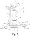
FIG. 1 is a perspective view of an orthopedic distal radius plate according to oneform of the present invention.FIG. 2 is a top plan view of the orthopedic distal radius plate ofFIG. 1 .FIG. 3 is a distal end view of the orthopedic distal radius plate ofFIG. 1 .- For the purpose of promoting an understanding of the principles of the present invention, reference will now be made to the embodiments illustrated in the drawings and specific language will be used to describe the same. It will nevertheless be understood that no limitation on the scope of the invention is hereby intended. Any alterations and further modifications in the described embodiments, and any further applications of the principles of the invention as described herein are contemplated as would normally occur to one skilled in the art to which the invention relates.
- The following descriptions and illustrations of non-limiting embodiments of the present invention are exemplary in nature, it being understood that the descriptions and illustrations related thereto are in no way intended to limit the inventions disclosed herein and/or their applications and/or uses.
- The bone plate fixation system disclosed herein provides a stable connection between a bone and a bone plate using a plurality of fasteners that permit different angles to be obtained between the bone plate and the fastener. The fasteners also lock into the bone plate to prevent or at least inhibit fastener back out. While fastener receiving openings in the bone plate are located in fixed positions, the angle variability allows the surgeon to reach denser areas of bone or capture bone fragments that are in irregular positions such as, for example, in cases of severe fractures with highly fragmented bones. The bone plate fixation system also allows the surgeon to choose the angle at which the screw is inserted through, and rigidly affixed in, an opening in the plate. Moreover, the bone plate fixation system allows a surgeon to direct a fastener toward a bone fragment that is not necessarily located along the axis of the opening in the plate. The system also provides flexibility in the placement of the plate in relation to the bone fracture, and allows the surgeon to choose the angle at which the fastener is inserted into the plate, which in turn leads to better tailoring of the system to the specific nature and characteristics of the bone and bone fracture being treated.
- Referring to
FIGS. 1-3 , shown therein is a boneplate fixation system 10according to one form of the invention that generally includes abone plate 12 and a plurality of bone anchors 14 that are configured to securely anchor thebone plate 12 to a bone. In the illustrated embodiment of the invention, thebone plate 12 is configured for fixation of fractures, non-unions and osteotomies of the radius bone, and more particularly the distal radius bone. However, it should be understood that thebone plate 12 may be configured for use in association with other orthopedic surgeries or procedures associated with other bones or joints requiring fixation in addition to the distal radius bone. - In the illustrated embodiment, the bone anchors 14 are configured as bone screws having a head portion 16 configured for engagement with the
bone plate 12 and a threadedshank portion 18 configured for anchoring within bone. In one embodiment, the head portion 16 includes at least one anti-back out feature orexternal thread 17 that engages a portion of thebone plate 12 to prevent or inhibit displacement or back out of thebone anchor 14 from thebone plate 12. As will be described in further detail below, the anti-back out feature orexternal thread 17 is adapted to engage, associate with, or otherwise cooperate with fins or projections that extend radially inward into bone screw openings in thebone plate 12. In some embodiments, the anti-back outfeature 17 may be provided as a continuous ridge or a non-continuous ridge, and may comprise a portion of a revolution, one complete revolution, multiple revolutions, a single lead, or multiple leads. Additionally or alternatively, the head portion 16 ofbone screw 14 may include other features or elements that engage with and/or seat within corresponding features of thebone plate 12 to prevent or inhibit displacement or back out of thebone anchor 14 from thebone plate 12. For example, the head portion 16 may be provided with a series of dimples, ridges, bumps, textured areas, or any other surface features that engage with features of thebone plate 12. Additionally, the head portion 16 may be provided with a tool-receiving opening or recess that is sized and configured to receive a distal end of a driver instrument to drive thebone screw 14 into engagement with bone. The threadedshank portion 18 is provided with anexternal thread 19 configured for engagement with bone or bone tissue to anchor the bone screw 14 (and the bone plate 12) to the bone. In some embodiments, theexternal thread 19 formed about and extending along theshank portion 18 is courser (i.e., has a greater pitch) relative to theexternal thread 17 formed about the head portion 16. Additionally, the distal end of threadedshank 18 may be fluted or may include another type of cutting element to provide thebone screw 14 with self-tapping or self-drilling capabilities. - Although the bone anchors 14 are illustrated and described as bone screws, it should be appreciated that other types and configurations of bone anchors or fasteners are also contemplated for use in association with the
bone plate 12 to secure thebone plate 12 to the underlying bone. For example, in other embodiments of the bone anchors 14, theshank portion 18 may be provided as a smooth, non-threaded shank such as, for example, a pin or peg. Other embodiments of the bone anchors 14 are also contemplated where the head portion 16 is smooth and is not provided with an anti-back out feature orexternal thread 17. Additionally, it should be understood that the bone anchors 14 may be made out of any suitable biocompatible material including, for example, biocompatible metallic materials such as stainless steel or titanium. However, it should also be understood that the bone anchors 14 may be formed of other suitable materials including other metallic materials, ceramic materials, composite materials, and resorbable or non-resorbable plastic or polymeric materials, - In the illustrated embodiment, the
bone plate 12 includes aplate body 20 extending along a central longitudinal axis L and generally including anelongate shaft portion 22 and a triangular-shapedhead portion 24 extending from theelongate shaft portion 22. Theplate body 20 may be formed of any suitable material having appropriate strength, manufacturability, autoclavability, and other desired performance characteristics. Suitable materials include, for example, titanium, stainless steel, cobalt chrome, polyetheretherketone (PEEK), polyethylene, ultra high molecular weight polyethylene (UHMWPE), resorbable polylactic acid (PLA), polyglycolic acid (PGA), combinations or alloys of such materials, or any other appropriate material that has sufficient strength to provide fixation to the bone while also having sufficient biocompatibility for implantation within the body. - In the illustrated embodiment, the
plate body 20 defines anouter perimeter 26 that is substantially symmetrical relative to the longitudinal axis L, and also includes anupper plate surface 28 and a lowerbone engagement surface 30 that is shaped and configured to generally conform to the outer surface of the underlying bony structure (i.e., the distal radius bone and/or the radial head). In one embodiment, the lowerbone engagement surface 30 may have an arcuate or curved shape that generally conforms with the outer contour of the underlying bone. Additionally, the lowerbone engagement surface 30 may have a convex curvature and/or a concave curvature. As illustrated inFIG. 3 , in the illustrated embodiment of theplate body 20, the lowerbone engagement surface 30 of the triangular-shapedhead portion 24 is provided withaconvex curvature 32 and one or moreconcave curvatures 34a, 34b located on either side of theconvex curvature 32. Although thecurvatures bone engagement surface 30 may be provided with curvatures that extend generally along a length of the plate body 20 (i.e., in a direction along the longitudinal axis L). Additionally, in the illustrated embodiment, theplate body 20 includes aproximal end surface 36 having a convex profile or curvature, and adistal end surface 38 also having a convex curvature or profile, and with the convex profiles of the end surfaces 36, 38 each being substantially centered relative to the longitudinal axis L and generally symmetrical relative to the longitudinal axis L, As should be appreciated, the symmetrical shape and configuration of theplate body 20 allows thesame bone plate 12 to be used for right-side and left-side applications. - In one embodiment, the
bone plate 12 combines features of polyaxial fixation with a low profile and lower bone engagement surface contouring that enables theplate body 20 to conform closely to the underlying bone. The lower surface contouring not only minimizes prominence of the plate body 20 (and therefore reduces potential for soft tissue irritation), but also facilitates fracture reduction and stabilization by allowing, if desired, mid-portions of the plate body to be compressed to bone to achieve a buttressing effect. This effect helps, among other things, to resist torque and bending during fracture healing. Once securely fixed in place using such compression techniques, the plate body produces a buttress effect to the fracture site to help prevent loss of reduction and enhance overall fracture fixation. Lower surface contouring also allows additional screw convergence in metaphyseal areas of the bone. - In the illustrated embodiment, the
plate body 20 includes a number ofbone screw openings 40 extending through the thickness of the plate from theupper plate surface 28 to the lowerbone engagement surface 30. Thebone screw openings 40 are each configured to receive a corresponding one of the bone screws 14 therethrough which in turn extend into bone to securely anchor theplate body 20 to the bone. Each of thebone screw openings 40 has aninner surface 42 and a plurality offlexible fins 44 integrally connected to and protruding radially inward from theinner surface 42. The primary purpose offins 44 is to engage the anti-back out feature orexternal thread 17 on the head portion 16 of thebone screw 14 in order to secure thebone screw 14 at a desired position and at a desired angle relative to theplate body 20. - As opposed to threaded bone screw openings which rigidly engage threads formed along a screw head and limit the surgeon's ability to angle the bone screw relative to the central axis of the threaded opening, the
flexible fins 44 engage the anti-back out feature orexternal thread 17 on thehead portion 14 and are structured to allow a degree of angulation of thebone screw 14 relative to the central axis of thebone screw opening 40. In one embodiment, theflexible fins 44 are deflectable or otherwise deformed by the head portion 16 of thebone screw 14 when thebone screw 14 is inserted into and driven through a corresponding one of thebone screw openings 40. As should be appreciated, theflexible fins 44 retain thebone screw 14 in position within the corresponding bone screw opening 40 relative to theplate body 20 to prevent or otherwise inhibit thebone screw 14 from loosening and/or backing out of theopening 40. As theexternal thread 17 of the bone screw head portion 16 begins to contact theflexible fins 44, thefins 44 engage theexternal thread 17 to hold thebone screw 14 in place at a desired angle and a desired position, even at angles that are angular offset (i.e., non-parallel) from the central axis of thebone screw opening 40. Engagement between thefins 44 and theexternal thread 17 securely affixes thebone screw 14 in position relative to thebone plate 12 at a desired position and insertion angle. - In one embodiment, the
flexible fins 44 are integrally connected to and protrude radially inward from theinner surface 42 of thebone screw openings 40. In another embodiment, theflexible fins 44 have a thickness that varies in radial direction, and more specifically have a thickness that tapers from a maximum thickness adjacent theinner surface 42 of theopening 40 to a minimum thickness at a terminal end of thefin 44. In a further embodiment, the bone screwsopenings 40 each have a relatively jagged or undulating inner circumference formed by the inwardly protrudingfins 44, and concavities or indentations are formed between adjacent pairs of tthefins 44 which extend to a location adjacent theinner surface 42 of theopenings 40. Additionally, thefins 44 have a generally round configurations wherein thefins 44 define convex protrusions extending inwardly into theopenings 40. In still other embodiments, thefins 44 may be provided in more than one layer (i.e., at more than one level or depth) within theopenings 40. Thefins 44 may also be provided with a circular shape, a trapezoidal shape, an oval shape, a rectangular shape, a rhomboid shape, a diamond shape, a triangular shape, or other suitable shapes or configurations. The sides or edges of thefins 44 may taper inwardly, outwardly, or may be generally parallel with one another. In someembodiments, each of thebone screw opening 40are provided with five of theflexible fins 44 protruding radially inward from theinner surface 42. However, it should be understood that thebone screw openings 40 may be provided with one, two, three, four, or six or more of theflexible fins 44. In one embodiment, theflexible fins 44 provide each of thebone screw openings 40 with a star-shaped configuration. However, other shapes and configurations of thebone screw openings 40 and/or theflexible fins 44 are also contemplated, examples of which are described in commonly-ownedU.S. Publication No. 2012/0323284 and commonly-ownedU.S. Publication No. 20130172943 . - In the illustrated embodiment, the
elongate shaft portion 22 of theplate body 20 includes a first plurality or grouping of thebone screw openings 40, and may also include anelongate slot 50 having a slot lengthlsextending generally along the longitudinal axis L, and a slot widthws extending across a width of theshaft portion 22 transverse to the longitudinal axis L. (FIG. 2 ). As should be appreciated, theelongate slot 50 is sized for receipt of a bone screw therethrough, with the shank portion of the bone screw anchored within the bone and the head portion of the bone screw positioned within a countersunkregion 52 of theelongate slot 50, with the countersunkregion 52 opening onto theupper surface 28 of theplate body 20. As should be further appreciated, thebone screw 14 may be displaced along the slot lengthls of theelongate slot 50 during compression of a bone fracture and prior to terminal/definitive tightening of thebone screw 14. Theelongate shaft portion 22 may also be provided with at least oneadditional aperture 54 that is sized for receipt of a pin, an elongate shaft, or a K-wire to provisionally attach the bone plate 1 2 to the bone prior to anchoring of thebone plate 12 to the bone via the bone screws 14. - Additionally, in the illustrated embodiment, the triangular-shaped
head portion 24 of theplate body 20 includes a second plurality or grouping of thebone screw openings 40, and may also include an elongate aperture or slot 60 (also referred to herein as "second elongate slot") extending therethrough. In one embodiment, theelongate aperture 60 has an aperture lengthla extending generally along the longitudinal axis L, and an aperture widthwa extending across a width of the triangular-shapedhead portion 24 transverse to the longitudinal axis L. (FIG. 2 ). In another embodiment, the aperture lengthla of theelongate aperture 60 in the triangular-shapedhead portion 24 extends in a direction substantially parallel with the slot lengthls of theelongate slot 50 in theelongate shaft portion 22. In yet another embodiment, theelongate slot 50 in theelongate shaft portion 22 is centered along the longitudinal axis L, and theelongate aperture 60 in the triangular-shapedhead portion 24 is laterally offset from the longitudinal axis L. In still another embodiment, the aperture widthwa of theelongate aperture 60 in the triangular-shapedhead portion 24 is less than the slot widthws of theelongate slot 50 in theelongate shaft portion 22. In some embodiment, theelongate aperture 60 is sized for receipt of a K-wire or attachment pin extending therethrough and adapted for anchoring in the bone. As should be appreciated, the K-wire or attachment pin may be displaced along the aperture lengthla of theelongate aperture 60 during compression of a bone fracture and prior to secure engagement of theplate body 20, and more particularly the triangular-shapedhead portion 24, to the bone. - In a further embodiment, the triangular-shaped
head portion 24 may include at least onefastener opening 62 extending therethrough that does not include theflexible fins 44 or other types or configurations of anti-back out features. Thefastener opening 62 can be configured, for example and without limitation, to engagingly receive an orthopedic instrument or device such as a drill guide, an insertion instrument or tool, or other types of device and/or instruments that are used in association with implantation of thebone plate 12 and engagement of thebone plate 12 to the bone. Thefastener opening 62 may be provided with a counter bore 64 to facilitate engagement of the instrument, tool or device with theplate body 20. - In another embodiment, the triangular-shaped
head portion 24 may further include anelongate visualization window 66 extending therethrough. In the illustrated embodiment, theelongate visualization window 66 is generally centered along the longitudinal axis L and has a shape that is substantially symmetrical relative to the longitudinal axis L. Theelongate visualization window 66 has a window lengthlw that extends in a direction transverse to the longitudinal axis L, and preferably in a direction substantially perpendicular to the longitudinal axis L (FIG. 2 ). Theelongate visualization window 66 has a trapezoidal shape. Theelongate visualization window 66 is defined by a pair of substantiallyparallel bases non-parallel legs peripheral side surfaces head portion 24 of theplate body 20. Thevisualization window 66 provides direct visualization of the bone that would otherwise be covered by thebone plate 12, and more particularly the triangular-shapedhead portion 24 of theplate body 20 adjacent the radial head of the distal radius. Theelongate visualization window 66 preferably remains unobstructed when theplate body 20 is attached to the bone to provide direct visualization of a portion of the bone located beneath theplate body 20. - In still yet another embodiment, the triangular-shaped
head portion 24 may include at least one additional pin-receiving aperture 68 sized for receipt of a pin, an elongate shaft, or a K-wire to provisionally attach thebone plate 12 to the bone prior to anchoring of thebone plate 12 to the bone via the bone screws 14. In the illustrated embodiment, the triangular- shapedhead portion 24 includes a pair of the pin-receivingapertures 68a, 68b positioned on opposite sides of the longitudinal axis L near the convexdistal end surface 38 of theplate body 20. - In the illustrated embodiment of the
plate body 20, theelongate slot 50 in theelongate shaft portion 22 and the at least onefastener opening 62 in the triangular-shapedhead portion 24 are each centered along the longitudinal axis L Additionally, in the illustrated embodiment, the first plurality or grouping of thebone screw openings 40 in the triangular- shapedhead portion 24 of theplate body 20 are arranged substantially symmetrical relative to the longitudinal axis L, and the second plurality or grouping of thebone screw openings 40 in theelongate shaft portion 22 of theplate body 20 are each substantially centered along the longitudinal axis L. As should be appreciated, the symmetrical layout of thebone screw openings 40 in theplate body 20 allows thesame bone plate 12 to be used for right-side and left- side applications. - In a further embodiment of the
plate body 20, the first plurality or grouping of thebone screw openings 40 in the triangular-shapedhead portion 24 are sized, shaped and configured substantially identical to the second plurality or grouping of thebone screw openings 40 in theelongate shaft portion 22 such that each of thebone screw openings 40 may receivebone screws 14 of the same type and general size. - In still another embodiment of the
plate body 20, theelongate shaft portion 22 of theplate body 20 includes two or more of thebone screw openings 40, and the triangular-shapedhead portion 24 includes a greater number of thebone screw openings 40 compared to theelongate shaft portion 22. In one specific embodiment, theelongate shaft portion 22 includes three of thebone screw openings 40, and the triangular-shapedhead portion 24 includes at least four of thebone screw openings 40. In another specific embodiment, the triangular-shapedhead portion 24 includes six of thebone screw openings 40 that are symmetrically arranged relative to the longitudinal axis L of theplate body 20. - While the systems and devices disclosed herein have been described for use in the treatment of the distal radius bone, it should be understood that the disclosed systems and devices may also be used in association with the treatment of other bones or bony structures.
Claims (5)
- A bone plate fixation system (10), comprising:a plurality of bone screws (14) each including a screw head (16) and a threaded shank (18) extending from said screw head (16) and adapted for anchoring within bone; anda bone plate (12) extending along a longitudinal axis (L) and having a plate body (20) including an elongate shaft portion (22) and a triangular-shaped head portion (24) extending from said elongate shaft portion (22);wherein said plate body (20) includes a number of bone screw openings (40) extending therethrough and each having an inner surface (42),
wherein said elongate shaft portion (22) of said plate body (20) includes a first plurality of said bone screw openings (40) and a first elongate slot (50) having a slot length extending generally parallel with said longitudinal axis (L); andwherein said triangular-shaped head portion (24) of said plate body (20) includes a second plurality of said bone screw openings (40) and a second elongate slot (60) having a slot length extending generally parallel with said longitudinal axis (L), said triangular-shaped head portion (24) further including an elongate visualization window (66) extending therethrough and having a window length extending in a direction transverse to said longitudinal axis (L);characterised in that:said bone screw openings (40) each having a plurality of flexible fins (44) integrally connected to and protruding radial inward from said inner surface (42),wherein said plurality of flexible fins (44) are deflectable by said screw head (16) of one of said bone screws (14) inserted into a corresponding one of said bone screw openings (40) to retain said one of said bone screws (14) in said corresponding one of said bone screw openings (40) relative to said plate body (20); andsaid elongate visualization window (66) in said triangular-shaped head portion (24) of said plate body (20) has a trapezoidal shape;wherein said elongate visualization window (66) is defined by a pair of substantially parallel bases (66a, 66b) extending along said window length, and a pair of non-parallel legs (66c, 66d) that extend substantially parallel with corresponding peripheral side surfaces (37a, 37b) defined by said triangular-shaped head portion (24) of said plate body (20). - The bone plate fixation system (10) of claim 1, wherein said first elongate slot (50) in said elongate shaft portion (22) is centered along said longitudinal axis (L); and said second elongate slot (60) in said triangular-shaped head portion (24) is laterally offset from said longitudinal axis (L); or
wherein said first elongate slot (50) in said elongate shaft portion (22) has a first slot width; and said second elongate slot (60) in said triangular-shaped head portion (24) has a second slot width that is less than said first slot width. - The bone plate fixation system (10) of claim 1, further comprising;a fastener extending through said first elongate slot (50) in said elongate shaft portion (22) and adapted for anchoring within the bone; anda K-wire or pin extending through said second elongate slot (60) in said triangular-shaped head portion (24) and adapted for anchoring within the bone.
- The bone plate fixation system (10) of claim 1, wherein said plate body (20) defines an outer perimeter that is substantially symmetrical relative to said longitudinal axis (L) and optionally wherein said screw head (16) of at least some of said plurality of bone screws (14) includes an external thread (17) engaged with said plurality of flexible fins (44) of a corresponding one of said bone screw openings (40) and further optionally wherein said plurality of flexible fins (44) provide each of said plurality of bone screw openings (40) with a star-shaped configuration.
- The bone plate fixation system (10) of claim 1, wherein said elongate visualization window (66) remains unobstructed when said plate body (20) is attached to the bone to provide direct visualization of a portion of the bone through said plate body (20) and optionally wherein said second plurality of said bone screw openings (40) in said triangular-shaped head portion (24) are arranged substantially symmetrical relative to said longitudinal axis (L);wherein said first plurality of said bone screw openings (40) in said elongate shaft portion (22) are each substantially centered along said longitudinal axis (L); andwherein said second plurality of said bone screw openings (40) in said triangular-shaped head portion (24) are sized, shaped and configured substantially identical to said first plurality of said bone screw openings (40) in said elongate shaft portion (22).
Priority Applications (1)
| Application Number | Priority Date | Filing Date | Title |
|---|---|---|---|
| EP23203396.9AEP4282359A3 (en) | 2013-12-23 | 2014-12-23 | Distal radius plate |
Applications Claiming Priority (2)
| Application Number | Priority Date | Filing Date | Title |
|---|---|---|---|
| US201361920352P | 2013-12-23 | 2013-12-23 | |
| PCT/US2014/072108WO2015100304A1 (en) | 2013-12-23 | 2014-12-23 | Distal radius plate |
Related Child Applications (1)
| Application Number | Title | Priority Date | Filing Date |
|---|---|---|---|
| EP23203396.9ADivisionEP4282359A3 (en) | 2013-12-23 | 2014-12-23 | Distal radius plate |
Publications (2)
| Publication Number | Publication Date |
|---|---|
| EP3086726A1 EP3086726A1 (en) | 2016-11-02 |
| EP3086726B1true EP3086726B1 (en) | 2023-10-18 |
Family
ID=52283002
Family Applications (2)
| Application Number | Title | Priority Date | Filing Date |
|---|---|---|---|
| EP14824330.6AActiveEP3086726B1 (en) | 2013-12-23 | 2014-12-23 | Distal radius plate |
| EP23203396.9APendingEP4282359A3 (en) | 2013-12-23 | 2014-12-23 | Distal radius plate |
Family Applications After (1)
| Application Number | Title | Priority Date | Filing Date |
|---|---|---|---|
| EP23203396.9APendingEP4282359A3 (en) | 2013-12-23 | 2014-12-23 | Distal radius plate |
Country Status (4)
| Country | Link |
|---|---|
| US (2) | US10231766B2 (en) |
| EP (2) | EP3086726B1 (en) |
| CN (2) | CN106028988A (en) |
| WO (1) | WO2015100304A1 (en) |
Families Citing this family (26)
| Publication number | Priority date | Publication date | Assignee | Title |
|---|---|---|---|---|
| US7951176B2 (en) | 2003-05-30 | 2011-05-31 | Synthes Usa, Llc | Bone plate |
| US11259851B2 (en) | 2003-08-26 | 2022-03-01 | DePuy Synthes Products, Inc. | Bone plate |
| DE20321551U1 (en) | 2003-08-26 | 2007-12-27 | Synthes Gmbh | bone plate |
| US11291484B2 (en) | 2004-01-26 | 2022-04-05 | DePuy Synthes Products, Inc. | Highly-versatile variable-angle bone plate system |
| US8574268B2 (en) | 2004-01-26 | 2013-11-05 | DePuy Synthes Product, LLC | Highly-versatile variable-angle bone plate system |
| US10905476B2 (en) | 2016-09-08 | 2021-02-02 | DePuy Synthes Products, Inc. | Variable angle bone plate |
| US10624686B2 (en) | 2016-09-08 | 2020-04-21 | DePuy Synthes Products, Inc. | Variable angel bone plate |
| US10820930B2 (en) | 2016-09-08 | 2020-11-03 | DePuy Synthes Products, Inc. | Variable angle bone plate |
| WO2019169292A1 (en)* | 2018-03-02 | 2019-09-06 | The Board Of Regents Of The University Of Nebraska | Distal radius plating system |
| EP4108194A1 (en) | 2018-03-02 | 2022-12-28 | Stryker European Holdings I, LLC | Bone plates and associated screws |
| US11026727B2 (en) | 2018-03-20 | 2021-06-08 | DePuy Synthes Products, Inc. | Bone plate with form-fitting variable-angle locking hole |
| US10772665B2 (en)* | 2018-03-29 | 2020-09-15 | DePuy Synthes Products, Inc. | Locking structures for affixing bone anchors to a bone plate, and related systems and methods |
| US11013541B2 (en) | 2018-04-30 | 2021-05-25 | DePuy Synthes Products, Inc. | Threaded locking structures for affixing bone anchors to a bone plate, and related systems and methods |
| CN109077791B (en)* | 2018-11-02 | 2024-02-13 | 河北瑞鹤医疗器械有限公司 | Fixing screw for pedicle screw and pedicle screw suit |
| CN109077790B (en)* | 2018-11-02 | 2024-02-09 | 河北瑞鹤医疗器械有限公司 | Screw capable of clamping pedicle of vertebral arch on one side |
| US10925651B2 (en) | 2018-12-21 | 2021-02-23 | DePuy Synthes Products, Inc. | Implant having locking holes with collection cavity for shavings |
| CN109965965A (en)* | 2019-03-06 | 2019-07-05 | 无锡市闻泰百得医疗器械有限公司 | A kind of universal bone plate of radius |
| US11129652B2 (en)* | 2019-04-17 | 2021-09-28 | Warsaw Orthopedic, Inc. | Adjustable-height bone plate system |
| US11278334B2 (en)* | 2019-05-22 | 2022-03-22 | DePuy Synthes Products, Inc. | Variable angle bone screw having a hardened head |
| US12070253B2 (en)* | 2019-06-07 | 2024-08-27 | Smith & Nephew, Inc. | Orthopedic implant with improved variable angle locking mechanism |
| WO2021010913A1 (en)* | 2019-07-18 | 2021-01-21 | Efa Veterinerlik Hizmetleri Tic. Ltd. Sti. | Fully anatomical poly-axial locking distal radius plate designed for quadrupeds |
| WO2021087627A1 (en)* | 2019-11-07 | 2021-05-14 | Bonebridge Ag | Fracture fixation plate |
| US11849983B2 (en)* | 2020-08-18 | 2023-12-26 | Field Orthopaedics Pty Ltd | Bone fixation system and method |
| US20240016526A1 (en)* | 2022-07-13 | 2024-01-18 | Stryker European Operations Limited | Bone plate and method for fixing a bone fragment to a bone |
| EP4454582A1 (en)* | 2023-04-27 | 2024-10-30 | Stryker European Operations Limited | Bone plate for securing a fractured bone |
| CN116650088B (en)* | 2023-07-26 | 2024-02-27 | 北京纳通医学研究院有限公司 | Distal radius plate and distal radius plate system |
Citations (2)
| Publication number | Priority date | Publication date | Assignee | Title |
|---|---|---|---|---|
| US20050240187A1 (en)* | 2004-04-22 | 2005-10-27 | Huebner Randall J | Expanded fixation of bones |
| US20130172943A1 (en)* | 2005-07-25 | 2013-07-04 | Smith & Nephew, Inc., A Delaware Corporation | Systems and methods for using polyaxial plates |
Family Cites Families (19)
| Publication number | Priority date | Publication date | Assignee | Title |
|---|---|---|---|---|
| US8574268B2 (en) | 2004-01-26 | 2013-11-05 | DePuy Synthes Product, LLC | Highly-versatile variable-angle bone plate system |
| US7137987B2 (en)* | 2004-07-02 | 2006-11-21 | Wright Medical Technology, Inc. | Distal radius bone plating system with locking and non-locking screws |
| US8430881B2 (en) | 2004-10-15 | 2013-04-30 | Baxano, Inc. | Mechanical tissue modification devices and methods |
| FI119969B (en) | 2005-05-06 | 2009-05-29 | Inion Ltd | Plate and system for attaching leg parts |
| CA2616798C (en) | 2005-07-25 | 2014-01-28 | Smith & Nephew, Inc. | Systems and methods for using polyaxial plates |
| KR101246113B1 (en)* | 2005-10-25 | 2013-03-20 | 앤썸 오르소패딕스, 엘엘씨 | Bone fastening assembly and bushing and screw for use therewith |
| FR2928259B1 (en) | 2008-03-07 | 2011-04-22 | D L P Sarl | MATERIAL FOR THE REDUCTION OF A FRACTURE, ESPECIALLY A DISTAL RADIUS FRACTURE |
| GB0914673D0 (en)* | 2009-08-24 | 2009-09-30 | Kumar Deepak | Fracture buttress fixation system |
| JP2013512042A (en)* | 2009-11-27 | 2013-04-11 | シンセス ゲゼルシャフト ミット ベシュレンクテル ハフツング | Planar fixation concept for distal radius fractures |
| FR2956972B1 (en)* | 2010-03-08 | 2012-12-28 | Memometal Technologies | ARTICULATED OSTEOSYNTHESIS PLATE |
| EP2563250B1 (en)* | 2010-04-27 | 2017-11-15 | Synthes GmbH | Bone fixation system including k-wire compression |
| EP2826432B1 (en)* | 2010-06-02 | 2020-02-12 | Synthes GmbH | Bone plate |
| GB2487331B (en)* | 2010-09-27 | 2012-10-24 | Acumed Llc | Instruments having a radiopaque region to facilitate positioning a bone plate on bone |
| WO2012050424A1 (en)* | 2010-10-14 | 2012-04-19 | Sai Yeong Leong | A distal radius plating system |
| EP2476388B1 (en)* | 2011-01-17 | 2014-10-29 | HG Medical GmbH | Osteosynthesis plate, in particular radius plate or ulnar plate, for stabilising bone fractures |
| AU2012271441B2 (en) | 2011-06-15 | 2017-02-02 | Smith & Nephew, Inc. | Variable angle locking implant |
| US20130006246A1 (en)* | 2011-06-30 | 2013-01-03 | Dodson Mark | Distal Radius Plate |
| CN202173466U (en) | 2011-08-06 | 2012-03-28 | 董慧平 | Pressurized bone plate for long bone reduction |
| CN203042413U (en)* | 2012-12-03 | 2013-07-10 | 浙江科惠医疗器械有限公司 | Universal locking and pressurizing bone plate |
- 2014
- 2014-12-23USUS15/107,766patent/US10231766B2/enactiveActive
- 2014-12-23CNCN201480076220.0Apatent/CN106028988A/enactivePending
- 2014-12-23EPEP14824330.6Apatent/EP3086726B1/enactiveActive
- 2014-12-23WOPCT/US2014/072108patent/WO2015100304A1/enactiveApplication Filing
- 2014-12-23CNCN202111394558.9Apatent/CN114010297A/enactivePending
- 2014-12-23EPEP23203396.9Apatent/EP4282359A3/enactivePending
- 2019
- 2019-01-25USUS16/257,508patent/US10973560B2/enactiveActive
Patent Citations (2)
| Publication number | Priority date | Publication date | Assignee | Title |
|---|---|---|---|---|
| US20050240187A1 (en)* | 2004-04-22 | 2005-10-27 | Huebner Randall J | Expanded fixation of bones |
| US20130172943A1 (en)* | 2005-07-25 | 2013-07-04 | Smith & Nephew, Inc., A Delaware Corporation | Systems and methods for using polyaxial plates |
Also Published As
| Publication number | Publication date |
|---|---|
| US20160317205A1 (en) | 2016-11-03 |
| WO2015100304A1 (en) | 2015-07-02 |
| US10231766B2 (en) | 2019-03-19 |
| EP4282359A3 (en) | 2024-02-21 |
| US20190150998A1 (en) | 2019-05-23 |
| CN106028988A (en) | 2016-10-12 |
| CN114010297A (en) | 2022-02-08 |
| EP4282359A2 (en) | 2023-11-29 |
| EP3086726A1 (en) | 2016-11-02 |
| US10973560B2 (en) | 2021-04-13 |
Similar Documents
| Publication | Publication Date | Title |
|---|---|---|
| US10973560B2 (en) | Distal radius plate | |
| US11896270B2 (en) | Systems and methods for using polyaxial plates | |
| US10327822B2 (en) | Systems and methods for using polyaxial plates | |
| US10405901B2 (en) | Variable angle locking implant | |
| US7951178B2 (en) | Bone plates with hybrid apertures | |
| US8518090B2 (en) | Fastener with serrated thread for attachment to a bone plate at a selectable angle | |
| EP1764052A1 (en) | Bone stabilization system | |
| EP3979934B1 (en) | Orthopedic implant with improved variable angle locking mechanism | |
| AU2013202741B2 (en) | Systems and methods for using polyaxial plates | |
| AU2016200490B2 (en) | Systems and methods for using polyaxial plates |
Legal Events
| Date | Code | Title | Description |
|---|---|---|---|
| PUAI | Public reference made under article 153(3) epc to a published international application that has entered the european phase | Free format text:ORIGINAL CODE: 0009012 | |
| 17P | Request for examination filed | Effective date:20160725 | |
| AK | Designated contracting states | Kind code of ref document:A1 Designated state(s):AL AT BE BG CH CY CZ DE DK EE ES FI FR GB GR HR HU IE IS IT LI LT LU LV MC MK MT NL NO PL PT RO RS SE SI SK SM TR | |
| AX | Request for extension of the european patent | Extension state:BA ME | |
| DAX | Request for extension of the european patent (deleted) | ||
| PUAG | Search results despatched under rule 164(2) epc together with communication from examining division | Free format text:ORIGINAL CODE: 0009017 | |
| STAA | Information on the status of an ep patent application or granted ep patent | Free format text:STATUS: EXAMINATION IS IN PROGRESS | |
| 17Q | First examination report despatched | Effective date:20170906 | |
| B565 | Issuance of search results under rule 164(2) epc | Effective date:20170906 | |
| RIC1 | Information provided on ipc code assigned before grant | Ipc:A61B 17/80 20060101AFI20170901BHEP | |
| GRAP | Despatch of communication of intention to grant a patent | Free format text:ORIGINAL CODE: EPIDOSNIGR1 | |
| STAA | Information on the status of an ep patent application or granted ep patent | Free format text:STATUS: GRANT OF PATENT IS INTENDED | |
| INTG | Intention to grant announced | Effective date:20230516 | |
| P01 | Opt-out of the competence of the unified patent court (upc) registered | Effective date:20230609 | |
| GRAS | Grant fee paid | Free format text:ORIGINAL CODE: EPIDOSNIGR3 | |
| GRAA | (expected) grant | Free format text:ORIGINAL CODE: 0009210 | |
| STAA | Information on the status of an ep patent application or granted ep patent | Free format text:STATUS: THE PATENT HAS BEEN GRANTED | |
| AK | Designated contracting states | Kind code of ref document:B1 Designated state(s):AL AT BE BG CH CY CZ DE DK EE ES FI FR GB GR HR HU IE IS IT LI LT LU LV MC MK MT NL NO PL PT RO RS SE SI SK SM TR | |
| REG | Reference to a national code | Ref country code:GB Ref legal event code:FG4D | |
| REG | Reference to a national code | Ref country code:CH Ref legal event code:EP | |
| REG | Reference to a national code | Ref country code:DE Ref legal event code:R096 Ref document number:602014088626 Country of ref document:DE | |
| REG | Reference to a national code | Ref country code:IE Ref legal event code:FG4D | |
| REG | Reference to a national code | Ref country code:LT Ref legal event code:MG9D | |
| REG | Reference to a national code | Ref country code:NL Ref legal event code:MP Effective date:20231018 | |
| REG | Reference to a national code | Ref country code:AT Ref legal event code:MK05 Ref document number:1621743 Country of ref document:AT Kind code of ref document:T Effective date:20231018 | |
| PG25 | Lapsed in a contracting state [announced via postgrant information from national office to epo] | Ref country code:NL Free format text:LAPSE BECAUSE OF FAILURE TO SUBMIT A TRANSLATION OF THE DESCRIPTION OR TO PAY THE FEE WITHIN THE PRESCRIBED TIME-LIMIT Effective date:20231018 | |
| PG25 | Lapsed in a contracting state [announced via postgrant information from national office to epo] | Ref country code:GR Free format text:LAPSE BECAUSE OF FAILURE TO SUBMIT A TRANSLATION OF THE DESCRIPTION OR TO PAY THE FEE WITHIN THE PRESCRIBED TIME-LIMIT Effective date:20240119 | |
| PG25 | Lapsed in a contracting state [announced via postgrant information from national office to epo] | Ref country code:IS Free format text:LAPSE BECAUSE OF FAILURE TO SUBMIT A TRANSLATION OF THE DESCRIPTION OR TO PAY THE FEE WITHIN THE PRESCRIBED TIME-LIMIT Effective date:20240218 | |
| PG25 | Lapsed in a contracting state [announced via postgrant information from national office to epo] | Ref country code:LT Free format text:LAPSE BECAUSE OF FAILURE TO SUBMIT A TRANSLATION OF THE DESCRIPTION OR TO PAY THE FEE WITHIN THE PRESCRIBED TIME-LIMIT Effective date:20231018 | |
| PG25 | Lapsed in a contracting state [announced via postgrant information from national office to epo] | Ref country code:AT Free format text:LAPSE BECAUSE OF FAILURE TO SUBMIT A TRANSLATION OF THE DESCRIPTION OR TO PAY THE FEE WITHIN THE PRESCRIBED TIME-LIMIT Effective date:20231018 | |
| PG25 | Lapsed in a contracting state [announced via postgrant information from national office to epo] | Ref country code:ES Free format text:LAPSE BECAUSE OF FAILURE TO SUBMIT A TRANSLATION OF THE DESCRIPTION OR TO PAY THE FEE WITHIN THE PRESCRIBED TIME-LIMIT Effective date:20231018 | |
| PG25 | Lapsed in a contracting state [announced via postgrant information from national office to epo] | Ref country code:LT Free format text:LAPSE BECAUSE OF FAILURE TO SUBMIT A TRANSLATION OF THE DESCRIPTION OR TO PAY THE FEE WITHIN THE PRESCRIBED TIME-LIMIT Effective date:20231018 Ref country code:IS Free format text:LAPSE BECAUSE OF FAILURE TO SUBMIT A TRANSLATION OF THE DESCRIPTION OR TO PAY THE FEE WITHIN THE PRESCRIBED TIME-LIMIT Effective date:20240218 Ref country code:GR Free format text:LAPSE BECAUSE OF FAILURE TO SUBMIT A TRANSLATION OF THE DESCRIPTION OR TO PAY THE FEE WITHIN THE PRESCRIBED TIME-LIMIT Effective date:20240119 Ref country code:ES Free format text:LAPSE BECAUSE OF FAILURE TO SUBMIT A TRANSLATION OF THE DESCRIPTION OR TO PAY THE FEE WITHIN THE PRESCRIBED TIME-LIMIT Effective date:20231018 Ref country code:BG Free format text:LAPSE BECAUSE OF FAILURE TO SUBMIT A TRANSLATION OF THE DESCRIPTION OR TO PAY THE FEE WITHIN THE PRESCRIBED TIME-LIMIT Effective date:20240118 Ref country code:AT Free format text:LAPSE BECAUSE OF FAILURE TO SUBMIT A TRANSLATION OF THE DESCRIPTION OR TO PAY THE FEE WITHIN THE PRESCRIBED TIME-LIMIT Effective date:20231018 Ref country code:PT Free format text:LAPSE BECAUSE OF FAILURE TO SUBMIT A TRANSLATION OF THE DESCRIPTION OR TO PAY THE FEE WITHIN THE PRESCRIBED TIME-LIMIT Effective date:20240219 | |
| PG25 | Lapsed in a contracting state [announced via postgrant information from national office to epo] | Ref country code:SE Free format text:LAPSE BECAUSE OF FAILURE TO SUBMIT A TRANSLATION OF THE DESCRIPTION OR TO PAY THE FEE WITHIN THE PRESCRIBED TIME-LIMIT Effective date:20231018 Ref country code:RS Free format text:LAPSE BECAUSE OF FAILURE TO SUBMIT A TRANSLATION OF THE DESCRIPTION OR TO PAY THE FEE WITHIN THE PRESCRIBED TIME-LIMIT Effective date:20231018 Ref country code:PL Free format text:LAPSE BECAUSE OF FAILURE TO SUBMIT A TRANSLATION OF THE DESCRIPTION OR TO PAY THE FEE WITHIN THE PRESCRIBED TIME-LIMIT Effective date:20231018 Ref country code:NO Free format text:LAPSE BECAUSE OF FAILURE TO SUBMIT A TRANSLATION OF THE DESCRIPTION OR TO PAY THE FEE WITHIN THE PRESCRIBED TIME-LIMIT Effective date:20240118 Ref country code:LV Free format text:LAPSE BECAUSE OF FAILURE TO SUBMIT A TRANSLATION OF THE DESCRIPTION OR TO PAY THE FEE WITHIN THE PRESCRIBED TIME-LIMIT Effective date:20231018 Ref country code:HR Free format text:LAPSE BECAUSE OF FAILURE TO SUBMIT A TRANSLATION OF THE DESCRIPTION OR TO PAY THE FEE WITHIN THE PRESCRIBED TIME-LIMIT Effective date:20231018 | |
| PG25 | Lapsed in a contracting state [announced via postgrant information from national office to epo] | Ref country code:DK Free format text:LAPSE BECAUSE OF FAILURE TO SUBMIT A TRANSLATION OF THE DESCRIPTION OR TO PAY THE FEE WITHIN THE PRESCRIBED TIME-LIMIT Effective date:20231018 | |
| REG | Reference to a national code | Ref country code:DE Ref legal event code:R097 Ref document number:602014088626 Country of ref document:DE | |
| PG25 | Lapsed in a contracting state [announced via postgrant information from national office to epo] | Ref country code:CZ Free format text:LAPSE BECAUSE OF FAILURE TO SUBMIT A TRANSLATION OF THE DESCRIPTION OR TO PAY THE FEE WITHIN THE PRESCRIBED TIME-LIMIT Effective date:20231018 | |
| PG25 | Lapsed in a contracting state [announced via postgrant information from national office to epo] | Ref country code:SK Free format text:LAPSE BECAUSE OF FAILURE TO SUBMIT A TRANSLATION OF THE DESCRIPTION OR TO PAY THE FEE WITHIN THE PRESCRIBED TIME-LIMIT Effective date:20231018 | |
| PG25 | Lapsed in a contracting state [announced via postgrant information from national office to epo] | Ref country code:SM Free format text:LAPSE BECAUSE OF FAILURE TO SUBMIT A TRANSLATION OF THE DESCRIPTION OR TO PAY THE FEE WITHIN THE PRESCRIBED TIME-LIMIT Effective date:20231018 Ref country code:SK Free format text:LAPSE BECAUSE OF FAILURE TO SUBMIT A TRANSLATION OF THE DESCRIPTION OR TO PAY THE FEE WITHIN THE PRESCRIBED TIME-LIMIT Effective date:20231018 Ref country code:RO Free format text:LAPSE BECAUSE OF FAILURE TO SUBMIT A TRANSLATION OF THE DESCRIPTION OR TO PAY THE FEE WITHIN THE PRESCRIBED TIME-LIMIT Effective date:20231018 Ref country code:IT Free format text:LAPSE BECAUSE OF FAILURE TO SUBMIT A TRANSLATION OF THE DESCRIPTION OR TO PAY THE FEE WITHIN THE PRESCRIBED TIME-LIMIT Effective date:20231018 Ref country code:EE Free format text:LAPSE BECAUSE OF FAILURE TO SUBMIT A TRANSLATION OF THE DESCRIPTION OR TO PAY THE FEE WITHIN THE PRESCRIBED TIME-LIMIT Effective date:20231018 Ref country code:DK Free format text:LAPSE BECAUSE OF FAILURE TO SUBMIT A TRANSLATION OF THE DESCRIPTION OR TO PAY THE FEE WITHIN THE PRESCRIBED TIME-LIMIT Effective date:20231018 Ref country code:CZ Free format text:LAPSE BECAUSE OF FAILURE TO SUBMIT A TRANSLATION OF THE DESCRIPTION OR TO PAY THE FEE WITHIN THE PRESCRIBED TIME-LIMIT Effective date:20231018 | |
| REG | Reference to a national code | Ref country code:CH Ref legal event code:PL | |
| PLBE | No opposition filed within time limit | Free format text:ORIGINAL CODE: 0009261 | |
| STAA | Information on the status of an ep patent application or granted ep patent | Free format text:STATUS: NO OPPOSITION FILED WITHIN TIME LIMIT | |
| PG25 | Lapsed in a contracting state [announced via postgrant information from national office to epo] | Ref country code:LU Free format text:LAPSE BECAUSE OF NON-PAYMENT OF DUE FEES Effective date:20231223 | |
| PG25 | Lapsed in a contracting state [announced via postgrant information from national office to epo] | Ref country code:MC Free format text:LAPSE BECAUSE OF FAILURE TO SUBMIT A TRANSLATION OF THE DESCRIPTION OR TO PAY THE FEE WITHIN THE PRESCRIBED TIME-LIMIT Effective date:20231018 | |
| REG | Reference to a national code | Ref country code:BE Ref legal event code:MM Effective date:20231231 | |
| PG25 | Lapsed in a contracting state [announced via postgrant information from national office to epo] | Ref country code:MC Free format text:LAPSE BECAUSE OF FAILURE TO SUBMIT A TRANSLATION OF THE DESCRIPTION OR TO PAY THE FEE WITHIN THE PRESCRIBED TIME-LIMIT Effective date:20231018 Ref country code:LU Free format text:LAPSE BECAUSE OF NON-PAYMENT OF DUE FEES Effective date:20231223 | |
| 26N | No opposition filed | Effective date:20240719 | |
| REG | Reference to a national code | Ref country code:IE Ref legal event code:MM4A | |
| PG25 | Lapsed in a contracting state [announced via postgrant information from national office to epo] | Ref country code:IE Free format text:LAPSE BECAUSE OF NON-PAYMENT OF DUE FEES Effective date:20231223 | |
| PG25 | Lapsed in a contracting state [announced via postgrant information from national office to epo] | Ref country code:BE Free format text:LAPSE BECAUSE OF NON-PAYMENT OF DUE FEES Effective date:20231231 | |
| PG25 | Lapsed in a contracting state [announced via postgrant information from national office to epo] | Ref country code:CH Free format text:LAPSE BECAUSE OF NON-PAYMENT OF DUE FEES Effective date:20231231 | |
| PG25 | Lapsed in a contracting state [announced via postgrant information from national office to epo] | Ref country code:SI Free format text:LAPSE BECAUSE OF FAILURE TO SUBMIT A TRANSLATION OF THE DESCRIPTION OR TO PAY THE FEE WITHIN THE PRESCRIBED TIME-LIMIT Effective date:20231018 | |
| PG25 | Lapsed in a contracting state [announced via postgrant information from national office to epo] | Ref country code:SI Free format text:LAPSE BECAUSE OF FAILURE TO SUBMIT A TRANSLATION OF THE DESCRIPTION OR TO PAY THE FEE WITHIN THE PRESCRIBED TIME-LIMIT Effective date:20231018 Ref country code:IE Free format text:LAPSE BECAUSE OF NON-PAYMENT OF DUE FEES Effective date:20231223 Ref country code:CH Free format text:LAPSE BECAUSE OF NON-PAYMENT OF DUE FEES Effective date:20231231 Ref country code:BE Free format text:LAPSE BECAUSE OF NON-PAYMENT OF DUE FEES Effective date:20231231 | |
| PGFP | Annual fee paid to national office [announced via postgrant information from national office to epo] | Ref country code:DE Payment date:20241029 Year of fee payment:11 | |
| PGFP | Annual fee paid to national office [announced via postgrant information from national office to epo] | Ref country code:GB Payment date:20241001 Year of fee payment:11 | |
| PGFP | Annual fee paid to national office [announced via postgrant information from national office to epo] | Ref country code:FR Payment date:20241111 Year of fee payment:11 | |
| PG25 | Lapsed in a contracting state [announced via postgrant information from national office to epo] | Ref country code:FI Free format text:LAPSE BECAUSE OF FAILURE TO SUBMIT A TRANSLATION OF THE DESCRIPTION OR TO PAY THE FEE WITHIN THE PRESCRIBED TIME-LIMIT Effective date:20231019 | |
| PG25 | Lapsed in a contracting state [announced via postgrant information from national office to epo] | Ref country code:CY Free format text:LAPSE BECAUSE OF FAILURE TO SUBMIT A TRANSLATION OF THE DESCRIPTION OR TO PAY THE FEE WITHIN THE PRESCRIBED TIME-LIMIT; INVALID AB INITIO Effective date:20141223 | |
| PG25 | Lapsed in a contracting state [announced via postgrant information from national office to epo] | Ref country code:HU Free format text:LAPSE BECAUSE OF FAILURE TO SUBMIT A TRANSLATION OF THE DESCRIPTION OR TO PAY THE FEE WITHIN THE PRESCRIBED TIME-LIMIT; INVALID AB INITIO Effective date:20141223 |