EP3086693B1 - Dispensing ingredients from a beverage cartridge - Google Patents
Dispensing ingredients from a beverage cartridgeDownload PDFInfo
- Publication number
- EP3086693B1 EP3086693B1EP14874578.9AEP14874578AEP3086693B1EP 3086693 B1EP3086693 B1EP 3086693B1EP 14874578 AEP14874578 AEP 14874578AEP 3086693 B1EP3086693 B1EP 3086693B1
- Authority
- EP
- European Patent Office
- Prior art keywords
- beverage
- cartridge
- dispensing
- pod
- storage compartments
- Prior art date
- Legal status (The legal status is an assumption and is not a legal conclusion. Google has not performed a legal analysis and makes no representation as to the accuracy of the status listed.)
- Active
Links
Images


Classifications
- B—PERFORMING OPERATIONS; TRANSPORTING
- B65—CONVEYING; PACKING; STORING; HANDLING THIN OR FILAMENTARY MATERIAL
- B65D—CONTAINERS FOR STORAGE OR TRANSPORT OF ARTICLES OR MATERIALS, e.g. BAGS, BARRELS, BOTTLES, BOXES, CANS, CARTONS, CRATES, DRUMS, JARS, TANKS, HOPPERS, FORWARDING CONTAINERS; ACCESSORIES, CLOSURES, OR FITTINGS THEREFOR; PACKAGING ELEMENTS; PACKAGES
- B65D81/00—Containers, packaging elements, or packages, for contents presenting particular transport or storage problems, or adapted to be used for non-packaging purposes after removal of contents
- B65D81/32—Containers, packaging elements, or packages, for contents presenting particular transport or storage problems, or adapted to be used for non-packaging purposes after removal of contents for packaging two or more different materials which must be maintained separate prior to use in admixture
- A—HUMAN NECESSITIES
- A47—FURNITURE; DOMESTIC ARTICLES OR APPLIANCES; COFFEE MILLS; SPICE MILLS; SUCTION CLEANERS IN GENERAL
- A47J—KITCHEN EQUIPMENT; COFFEE MILLS; SPICE MILLS; APPARATUS FOR MAKING BEVERAGES
- A47J31/00—Apparatus for making beverages
- A47J31/24—Coffee-making apparatus in which hot water is passed through the filter under pressure, i.e. in which the coffee grounds are extracted under pressure
- A47J31/34—Coffee-making apparatus in which hot water is passed through the filter under pressure, i.e. in which the coffee grounds are extracted under pressure with hot water under liquid pressure
- A47J31/36—Coffee-making apparatus in which hot water is passed through the filter under pressure, i.e. in which the coffee grounds are extracted under pressure with hot water under liquid pressure with mechanical pressure-producing means
- A47J31/3604—Coffee-making apparatus in which hot water is passed through the filter under pressure, i.e. in which the coffee grounds are extracted under pressure with hot water under liquid pressure with mechanical pressure-producing means with a mechanism arranged to move the brewing chamber between loading, infusing and ejecting stations
- A47J31/3623—Cartridges being employed
- A—HUMAN NECESSITIES
- A47—FURNITURE; DOMESTIC ARTICLES OR APPLIANCES; COFFEE MILLS; SPICE MILLS; SUCTION CLEANERS IN GENERAL
- A47J—KITCHEN EQUIPMENT; COFFEE MILLS; SPICE MILLS; APPARATUS FOR MAKING BEVERAGES
- A47J31/00—Apparatus for making beverages
- A47J31/40—Beverage-making apparatus with dispensing means for adding a measured quantity of ingredients, e.g. coffee, water, sugar, cocoa, milk, tea
- A47J31/405—Beverage-making apparatus with dispensing means for adding a measured quantity of ingredients, e.g. coffee, water, sugar, cocoa, milk, tea with one or more infusion chambers moving successively between loading, infusing and dumping stations
- A—HUMAN NECESSITIES
- A47—FURNITURE; DOMESTIC ARTICLES OR APPLIANCES; COFFEE MILLS; SPICE MILLS; SUCTION CLEANERS IN GENERAL
- A47J—KITCHEN EQUIPMENT; COFFEE MILLS; SPICE MILLS; APPARATUS FOR MAKING BEVERAGES
- A47J31/00—Apparatus for making beverages
- A47J31/40—Beverage-making apparatus with dispensing means for adding a measured quantity of ingredients, e.g. coffee, water, sugar, cocoa, milk, tea
- A47J31/407—Beverage-making apparatus with dispensing means for adding a measured quantity of ingredients, e.g. coffee, water, sugar, cocoa, milk, tea with ingredient-containing cartridges; Cartridge-perforating means
- A—HUMAN NECESSITIES
- A47—FURNITURE; DOMESTIC ARTICLES OR APPLIANCES; COFFEE MILLS; SPICE MILLS; SUCTION CLEANERS IN GENERAL
- A47J—KITCHEN EQUIPMENT; COFFEE MILLS; SPICE MILLS; APPARATUS FOR MAKING BEVERAGES
- A47J31/00—Apparatus for making beverages
- A47J31/44—Parts or details or accessories of beverage-making apparatus
- A47J31/4492—Means to read code provided on ingredient pod or cartridge
- A—HUMAN NECESSITIES
- A47—FURNITURE; DOMESTIC ARTICLES OR APPLIANCES; COFFEE MILLS; SPICE MILLS; SUCTION CLEANERS IN GENERAL
- A47J—KITCHEN EQUIPMENT; COFFEE MILLS; SPICE MILLS; APPARATUS FOR MAKING BEVERAGES
- A47J31/00—Apparatus for making beverages
- A47J31/44—Parts or details or accessories of beverage-making apparatus
- A47J31/46—Dispensing spouts, pumps, drain valves or like liquid transporting devices
- B—PERFORMING OPERATIONS; TRANSPORTING
- B65—CONVEYING; PACKING; STORING; HANDLING THIN OR FILAMENTARY MATERIAL
- B65D—CONTAINERS FOR STORAGE OR TRANSPORT OF ARTICLES OR MATERIALS, e.g. BAGS, BARRELS, BOTTLES, BOXES, CANS, CARTONS, CRATES, DRUMS, JARS, TANKS, HOPPERS, FORWARDING CONTAINERS; ACCESSORIES, CLOSURES, OR FITTINGS THEREFOR; PACKAGING ELEMENTS; PACKAGES
- B65D25/00—Details of other kinds or types of rigid or semi-rigid containers
- B65D25/02—Internal fittings
- B65D25/04—Partitions
- B—PERFORMING OPERATIONS; TRANSPORTING
- B65—CONVEYING; PACKING; STORING; HANDLING THIN OR FILAMENTARY MATERIAL
- B65D—CONTAINERS FOR STORAGE OR TRANSPORT OF ARTICLES OR MATERIALS, e.g. BAGS, BARRELS, BOTTLES, BOXES, CANS, CARTONS, CRATES, DRUMS, JARS, TANKS, HOPPERS, FORWARDING CONTAINERS; ACCESSORIES, CLOSURES, OR FITTINGS THEREFOR; PACKAGING ELEMENTS; PACKAGES
- B65D81/00—Containers, packaging elements, or packages, for contents presenting particular transport or storage problems, or adapted to be used for non-packaging purposes after removal of contents
- B65D81/32—Containers, packaging elements, or packages, for contents presenting particular transport or storage problems, or adapted to be used for non-packaging purposes after removal of contents for packaging two or more different materials which must be maintained separate prior to use in admixture
- B65D81/3261—Flexible containers having several compartments
- B65D81/3266—Flexible containers having several compartments separated by a common rupturable seal, a clip or other removable fastening device
- B—PERFORMING OPERATIONS; TRANSPORTING
- B65—CONVEYING; PACKING; STORING; HANDLING THIN OR FILAMENTARY MATERIAL
- B65D—CONTAINERS FOR STORAGE OR TRANSPORT OF ARTICLES OR MATERIALS, e.g. BAGS, BARRELS, BOTTLES, BOXES, CANS, CARTONS, CRATES, DRUMS, JARS, TANKS, HOPPERS, FORWARDING CONTAINERS; ACCESSORIES, CLOSURES, OR FITTINGS THEREFOR; PACKAGING ELEMENTS; PACKAGES
- B65D85/00—Containers, packaging elements or packages, specially adapted for particular articles or materials
- B65D85/70—Containers, packaging elements or packages, specially adapted for particular articles or materials for materials not otherwise provided for
- B65D85/804—Disposable containers or packages with contents which are mixed, infused or dissolved in situ, i.e. without having been previously removed from the package
- B65D85/8043—Packages adapted to allow liquid to pass through the contents
- B65D85/8049—Details of the inlet
- B—PERFORMING OPERATIONS; TRANSPORTING
- B65—CONVEYING; PACKING; STORING; HANDLING THIN OR FILAMENTARY MATERIAL
- B65D—CONTAINERS FOR STORAGE OR TRANSPORT OF ARTICLES OR MATERIALS, e.g. BAGS, BARRELS, BOTTLES, BOXES, CANS, CARTONS, CRATES, DRUMS, JARS, TANKS, HOPPERS, FORWARDING CONTAINERS; ACCESSORIES, CLOSURES, OR FITTINGS THEREFOR; PACKAGING ELEMENTS; PACKAGES
- B65D85/00—Containers, packaging elements or packages, specially adapted for particular articles or materials
- B65D85/70—Containers, packaging elements or packages, specially adapted for particular articles or materials for materials not otherwise provided for
- B65D85/804—Disposable containers or packages with contents which are mixed, infused or dissolved in situ, i.e. without having been previously removed from the package
- B65D85/8043—Packages adapted to allow liquid to pass through the contents
- B65D85/8052—Details of the outlet
- B—PERFORMING OPERATIONS; TRANSPORTING
- B65—CONVEYING; PACKING; STORING; HANDLING THIN OR FILAMENTARY MATERIAL
- B65D—CONTAINERS FOR STORAGE OR TRANSPORT OF ARTICLES OR MATERIALS, e.g. BAGS, BARRELS, BOTTLES, BOXES, CANS, CARTONS, CRATES, DRUMS, JARS, TANKS, HOPPERS, FORWARDING CONTAINERS; ACCESSORIES, CLOSURES, OR FITTINGS THEREFOR; PACKAGING ELEMENTS; PACKAGES
- B65D85/00—Containers, packaging elements or packages, specially adapted for particular articles or materials
- B65D85/70—Containers, packaging elements or packages, specially adapted for particular articles or materials for materials not otherwise provided for
- B65D85/804—Disposable containers or packages with contents which are mixed, infused or dissolved in situ, i.e. without having been previously removed from the package
- B65D85/8043—Packages adapted to allow liquid to pass through the contents
- B65D85/8058—Coding means for the contents
- B—PERFORMING OPERATIONS; TRANSPORTING
- B65—CONVEYING; PACKING; STORING; HANDLING THIN OR FILAMENTARY MATERIAL
- B65D—CONTAINERS FOR STORAGE OR TRANSPORT OF ARTICLES OR MATERIALS, e.g. BAGS, BARRELS, BOTTLES, BOXES, CANS, CARTONS, CRATES, DRUMS, JARS, TANKS, HOPPERS, FORWARDING CONTAINERS; ACCESSORIES, CLOSURES, OR FITTINGS THEREFOR; PACKAGING ELEMENTS; PACKAGES
- B65D85/00—Containers, packaging elements or packages, specially adapted for particular articles or materials
- B65D85/70—Containers, packaging elements or packages, specially adapted for particular articles or materials for materials not otherwise provided for
- B65D85/804—Disposable containers or packages with contents which are mixed, infused or dissolved in situ, i.e. without having been previously removed from the package
- B65D85/8043—Packages adapted to allow liquid to pass through the contents
- B65D85/8067—Packages for several ingredients
- B—PERFORMING OPERATIONS; TRANSPORTING
- B65—CONVEYING; PACKING; STORING; HANDLING THIN OR FILAMENTARY MATERIAL
- B65D—CONTAINERS FOR STORAGE OR TRANSPORT OF ARTICLES OR MATERIALS, e.g. BAGS, BARRELS, BOTTLES, BOXES, CANS, CARTONS, CRATES, DRUMS, JARS, TANKS, HOPPERS, FORWARDING CONTAINERS; ACCESSORIES, CLOSURES, OR FITTINGS THEREFOR; PACKAGING ELEMENTS; PACKAGES
- B65D81/00—Containers, packaging elements, or packages, for contents presenting particular transport or storage problems, or adapted to be used for non-packaging purposes after removal of contents
- B65D81/32—Containers, packaging elements, or packages, for contents presenting particular transport or storage problems, or adapted to be used for non-packaging purposes after removal of contents for packaging two or more different materials which must be maintained separate prior to use in admixture
- B65D81/3261—Flexible containers having several compartments
- B—PERFORMING OPERATIONS; TRANSPORTING
- B65—CONVEYING; PACKING; STORING; HANDLING THIN OR FILAMENTARY MATERIAL
- B65D—CONTAINERS FOR STORAGE OR TRANSPORT OF ARTICLES OR MATERIALS, e.g. BAGS, BARRELS, BOTTLES, BOXES, CANS, CARTONS, CRATES, DRUMS, JARS, TANKS, HOPPERS, FORWARDING CONTAINERS; ACCESSORIES, CLOSURES, OR FITTINGS THEREFOR; PACKAGING ELEMENTS; PACKAGES
- B65D81/00—Containers, packaging elements, or packages, for contents presenting particular transport or storage problems, or adapted to be used for non-packaging purposes after removal of contents
- B65D81/32—Containers, packaging elements, or packages, for contents presenting particular transport or storage problems, or adapted to be used for non-packaging purposes after removal of contents for packaging two or more different materials which must be maintained separate prior to use in admixture
- B65D81/3283—Cylindrical or polygonal containers, e.g. bottles, with two or more substantially axially offset, side-by-side compartments for simultaneous dispensing
Definitions
- beverage brewing systemsare known in the art. For example, percolators and drip-type coffee makers have been used to make regular or "American"-type coffee. Hot water is generally passed through a container of coffee grinds so as to brew the coffee. The coffee then drips into a pot or a cup. Likewise, pressure -based devices have been used to make espresso-type beverages. Hot, pressurized water may be forced through the espresso grinds so as to brew the espresso. The espresso may then flow into the cup.
- beverage podsto dispense individual servings quickly and conveniently.
- the single serving beverage brewing podsare popular and typically comprise a sealed container having a top surface, a bottom surface and a filter.
- Some other podsmay be used for preparing beverages or other food products which contain a water soluble substance.
- the water soluble substancemay be a liquid or powdered ingredient for making a beverage such as coffee, tea or soup, fruit juice and desserts.
- Relevant state of the art documents relating to this subject-matterare, for example: EP 2,230,295 , EP 2,510,805 , WO 2013/066178 , US 2010/159077 , and EP 2,100,824 .
- the cartridgeincludes a plurality of storage compartments stacked in series within an interior of the cartridge.
- Each of the plurality of storage compartmentsincludes an inlet port, an outlet port opposite the inlet port, an ingredient contained between the inlet and outlet ports, and a seal covering the inlet and outlet ports.
- the cartridgecan be configured to allow a transfer medium to rupture the seal of each of the storage compartments and to enter the inlet port to dilute the ingredient in each storage compartment in series and to discharge the diluted ingredients out of the cartridge.
- a beverage dispenserincluding a cartridge having a plurality of storage compartments stacked on top of one another.
- Each of the plurality of storage compartmentsinclude an inlet port; an outlet port opposite the inlet port; an ingredient contained between the inlet and outlet ports; and a seal covering the inlet and outlet ports.
- the cartridgecan be configured to allow a transfer medium to rupture the seal of each of the storage compartments and to enter the inlet port to dilute the ingredient in each storage compartment in series and to discharge the diluted ingredients out of the cartridge.
- the beverage dispenserfurther includes a turret including a first station for dispensing a carbonated beverage from a cartridge that has been inserted into the beverage dispenser; a first dispensing head and a second dispensing head adjacent to the first dispensing head.
- the first and second dispensing headsare arranged and configured to move laterally such that one of the first and second dispensing heads is positioned over the first dispensing station for dispensing therefrom.
- FIG. 1is a perspective view of an example pod beverage dispenser 100 having a single dispensing head.
- the pod beverage dispenser 100can be configured to dispense beverages using pods that have been inserted into the pod beverage dispenser 100.
- the elements of the example pod beverage dispenser 100 as a wholeare mounted onto a dispenser frame 102.
- the dispenser frame 102may be made out of stainless steel, aluminum, other types of metals, or other types of substantially non-corrosive materials.
- the beverage dispenser 100may include a control system (not shown), a turret assembly 104, a dispensing station 106, an ejector assembly 108, and a loading assembly 110.
- the control systemcontrols the flow of diluent within the beverage dispenser 100.
- the control systemmay also be used to control the flow of carbon dioxide within the beverage dispenser 100.
- An example of one control system, injector assembly, ejector assembly, and loading assemblyis disclosed in U.S. Pat. Pub. No. 2005/0095158 A1 .
- FIG. 2illustrates details of the example turret assembly 104.
- a double head dispenseris shown.
- FIG. 2is a top plan view of the example turret assembly 104.
- the example turret assembly 104includes a hot beverage dispensing head 114 (e.g., coffee or tea) and a cold beverage dispensing head 116 (e.g., a carbonated soft drink (CSD)).
- the hot beverage dispensing head 114may be used to dispense any hot beverage
- the cold beverage dispensing head 116may be used to dispense any cold beverage.
- the hot beverage dispensing head 114may be configured to dispense hot water, hot milk, and/or other hot fluids through a beverage pod so as to dispense a hot beverage.
- the cold beverage dispensing head 116may be configured to dispense cold water, cold carbonated water, and/or other cold fluids through a beverage pod so as to dispense a cold beverage.
- the turret assembly 104includes a turret plate 118. In this example, the turret assembly 104 is substantially circular.
- the turret plate 118 of the turret assembly 104defines a plurality of apertures 120 for receiving a pod 122 (see FIG. 5 ).
- the turret assembly 104includes a turret shaft 124 positioned and fixed about the center of the turret plate 118 such that the turret plate 118 may spin thereon.
- the turret assembly 104includes the example dispensing station 106 (see FIG. 1 ). It is understood that the arrangement and configuration of the example dispensing station 106 may vary in other embodiments.
- the example dispensing station 106is a single dispensing station arranged and configured to dispense beverages via both the hot beverage dispensing head 114 and the cold beverage dispensing head 116.
- the hot beverage dispensing head 114 and the cold beverage dispensing head 116can slide side-to-side so that either the hot beverage dispensing head 114 or the cold beverage dispensing head 116 is centered over the dispensing station 106.
- the example dispensing station 106is configured to receive hot fluids from the hot beverage dispensing head 114 such that the pod beverage dispenser 100 dispenses a hot beverage.
- the example single dispensing station 106 of the turret assembly 104is shown configured to receive cold fluids from the cold beverage dispensing head 116 such that the pod beverage dispenser 100 dispenses a cold beverage.
- the linear displacement mechanismlaterally moves the hot beverage dispensing head 114 and the cold beverage dispensing head 116 side-to-side is well known in the art.
- a pneumatic cylinder 128is shown as providing the motive force. It is to be understood that any similar linear motion device may be used.
- FIG. 2Aa cross-sectional view of a portion of the beverage dispenser shown in FIG. 2 taken along line 2A-2A is depicted which includes a cam 130 and a hot beverage pod 132.
- the hot beverage dispensing head 114may operate in any orientation. In this example, the hot beverage dispensing head 114 is moved in position such that a hot beverage is dispensed from the pod beverage dispenser 100.
- the hot beverage pod 132can include a brewable material such as coffee grounds, tea leaves, or the like or the hot beverage pod 132 can include a hot beverage concentrate such as a liquid concentrate, a powder, freeze-dried crystals, or the like.
- the hot beverage concentratemay be made from a previously brewed beverage or brewed beverage concentrate.
- Hot water or other hot fluidsmay be dispensed from the hot beverage dispensing head 114 through the hot beverage pod 132 to dispense a hot beverage, such as, but not limited to, a coffee, tea, etc.
- FIG. 3Aa cross-sectional view of a portion of the beverage dispenser shown in FIG. 3 taken along line 3A-3A is depicted which includes the cam 130 and a cold beverage pod 134.
- the cold beverage dispensing head 116is in position such that a cold beverage is dispensed from the pod beverage dispenser 100.
- the cold beverage dispensing head 116may operate in any orientation.
- the cold beverage pod 134can include liquid concentrate or powder for forming a non-carbonated or carbonated beverage.
- Cold water, cold carbonated water, or other cold fluidsmay be dispensed from the cold beverage dispensing head 116 through the cold beverage pod 134 to dispense a cold beverage, such as, but not limited to a juice, a tea, a soft drink, etc.
- the cam 130is a rotating or sliding piece in a mechanical linkage used to transform rotary motion into linear motion or vice-versa.
- the cam 130is used to translate the dispensing head 114 towards and away from the pods. For example, upon rotating the cam 130 180 degrees, the dispensing head 114 is lowered onto the pod at the dispensing station with sufficient force so as to form a sealing engagement between the dispensing head 114 and the pod.
- a cam motormay drive the cam 130.
- the cam motormay be a conventional AC motor or a similar type of device.
- the camcan be replaced with other mechanisms that provide linear actuation, such as a pneumatic cylinder or a rack and pinion mechanism.
- the beverage dispenser 100may be configured to identify the type of pod 122 being inserted into the turret assembly 104.
- the configurationcan include detecting a machine readable element on each pod, such as, but not limited to, a radiofrequency identification tag (RFID), that corresponds to a reading device in the beverage dispenser 100.
- RFIDradiofrequency identification tag
- the recognition systemcan includes barcodes, magnetic strips, optical recognition, microchips, and the like, including combinations thereof.
- the method for recognitionmay include physical obstructions, such as, but not limited to, voids, bumps, ridges, holes, recesses, protrusions, and the like, including combinations thereof.
- the hot beverage dispensing head 114upon insertion of the hot beverage pod 132 into the turret assembly 104, the hot beverage dispensing head 114 would automatically index to the dispensing station 106.
- the cold beverage dispensing head 116upon insertion of the cold beverage pod 134 into the turret assembly 104, the cold beverage dispensing head 116 would automatically index to the dispensing station 106.
- the userdoes not have to specify the type of pod 122 being inserted in the turret assembly 104 of the beverage dispenser 100 because all of the information regarding the pod type, ingredients therein, number of compartments within the pod, etc. will be recognized by the identification system.
- the pod 122can be arranged and configured to be used within any type of pod beverage dispenser.
- a pod identifier module 52can detect the type of beverage pod inserted in the turret assembly 104.
- the pod identifier module 52may be a machine reader for reading one or more of an RFID tag, barcode, magnetic strip, optical symbol, microchip, and the like, such as, but not limited to, an RFID reader, a barcode reader, a magnetic strip reader, an optical sensor, or a microchip interface.
- An electronic controller 54may monitor and control the operation of the pod beverage dispenser 100 as a whole and each of the components therein.
- the electronic controller 54may be a microcontroller or a similar type of device. Once the identification of the hot beverage pod 132 is made, the electronic controller 54 may operate a turret plate motor 56, a linear displacement mechanism 58, and a cam motor 60. The correct pod compartment of the turret plate 118 may rotate into place and the hot beverage pod 132 may be dropped into the correct turret aperture 120 for the turret assembly 104.
- the electronic controller 54may be integrated with a user interface 62.
- the user interface 62may receive input from a consumer to identify the type of beverage pod inserted in the turret assembly 104.
- the user interface 62may receive selections of a pod on a user input screen or receive product code information provided on the pod packaging.
- the electronic controller 54may be integrated with other systems 64 (e.g. hot/cold/carbonated/ water controls) for automatic dispensing.
- FIG. 4an example alternative embodiment of a turret assembly 104a arranged and configured with two dispensing stations is illustrated. It is understood that the configuration of the two dispensing stations may vary in other embodiments.
- the turret assembly 104aincludes a first dispensing station 136 and a second dispensing station 138 for dispensing from a hot beverage dispensing head 114a and a cold beverage dispensing head 116a respectively.
- the first dispensing station 136is dedicated to coffee or any hot beverage
- the second dispensing station 138is dedicated to any cold beverage.
- the hot beverage dispensing head 114ais positioned above the first dispensing station 136 and the cold beverage dispensing head 116a is positioned above the second dispensing station 138.
- the turret assembly 104aUpon insertion of a hot beverage pod 132a the turret assembly 104a automatically indexes the hot beverage pod 132a to the first dispensing station 136 by rotating the turret plate 118 90°, for example. Similarly, upon insertion of a cold beverage pod 134a into the turret assembly 104a, the turret assembly 104a automatically indexes the cold beverage pod 134a to the second dispensing station 138 by rotating the turret plate 118 180°, for example. As described above, the control system 50 and a method for recognizing the type of pod inserted in the turret assembly 104a can be used. With two dispensing stations, the linear displacement mechanism 58 may not be present because the dispensing heads 114a, 116a may be laterally fixed over their respective dispensing stations 136, 138.
- FIG. 5a schematic of an example fluidic diagram 140 is illustrated for dispensing a beverage from the cold beverage pod 134.
- the example fluidic diagram 140includes a first diluent stream 142, a macro-ingredient stream 144, a mixing device 146, a mixed stream 148 exiting the mixing device 146, a second diluent stream 150 (e.g., ingredient transfer medium) entering the pod 122, and an ingredients stream 152 exiting the pod 122.
- a first diluent stream 142e.g., ingredient transfer medium
- the macro-ingredient stream 144typically has a viscosity and density much different from common diluents and must be thoroughly mixed to prevent stratification.
- the macro-ingredient stream 144may be a nutritive sweetener, such as, high fructose corn syrup (HFCS), liquid sucrose, an inverted sugar, or other such sweeteners.
- HFCShigh fructose corn syrup
- the macro-ingredient stream 144may be a non-sweetener beverage ingredient.
- the mixing device 146can be a conventional dispensing nozzle well known to those in the art.
- the mixed stream 148contains a mixture of the first diluent and the macro-ingredient stream 144 that is dispensed into a cup 154.
- the first diluentmay be water, carbonated water, or other beverage diluents.
- carbon dioxide (CO 2 ) gasis routed to the pod 122 to act as the ingredient transfer medium 150 to transfer the ingredients out of the pod 122 into the cup 154.
- the ingredients in the pod 122can have a viscosity and density similarly to common diluents and may not be prone to stratification.
- the ingredients in the pod 122may include one or more beverage micro-ingredient.
- the ingredientsmay be un-sweetened beverage ingredients, such as an unsweetened beverage micro-ingredient.
- the mixed stream 148 and the ingredients stream 152 dispensing in the cup 154are parallel to each other.
- the mixed stream 148 and the ingredients stream 152may be in one stream.
- the ingredient transfer medium 150may not be CO 2 .
- the mixed stream 148 of diluent and the macro-ingredient stream 144are routed through the pod 122 and becomes the ingredient transfer medium 150 to dispense the ingredients from the pod 122.
- the fluidic diagram 140may include a secondary diluent stream that branches off the diluent stream 142 upstream or downstream of the mixing device 146.
- the secondary diluent streammay be used as the ingredient transfer medium 150.
- the fluidic diagram 140aincludes a pod 122a, a macro ingredient source 141a, a CO 2 source 143 a, a H 2 O source 145a, and other beverage ingredient sources 147a.
- ingredients from the pod 122aare being dispensed into a cup 154a.
- the CO 2 source 143ahas a carbonator 149a that is used to generate carbonated water that is dispensed into the cup 154a.
- the CO 2 source 143amay have a removable CO 2 cylinder.
- the H 2 O source 145aincludes a heater 151a for generating hot water that can be dispensed in the cup 154a.
- the water source 145amay include a removable water reservoir or a water supply line. Water that does not undergo heating from the heater 151a may also be dispensed into the cup 154a.
- other ingredient sources 147ae.g., juice, dairy, milk, yogurt, etc. may be dispensed to the cup 154a.
- Ingredients that can be used in pods of the pod beverage dispenser 100include: traditional beverage syrup (nutritive or non-nutritive sweetened), un-sweetened beverage concentrate, un-sweetened beverage micro-ingredient, un-sweetened acid and acid-degradable beverage flavor components, non-nutritive or high-intensity sweetener can be included in the acid-degradable flavor component. It is to be appreciated that other ingredient scenarios may be possible.
- beverage dispensers and pods described hereincan be used to dispense either hot beverages (e.g., coffee, tea) or cold beverages (e.g., carbonated soft drinks).
- hot beveragese.g., coffee, tea
- cold beveragese.g., carbonated soft drinks
- the pods used to accomplish both the hot and cold beveragescan be similar in external geometries to allow for ease in the insertion into the beverage dispensers.
- the podscan be arranged in both serial (i.e., co-linearly) and parallel (i.e., perpendicularly or radially) configurations to accomplish different dispensing scenarios, as needed.
- add-on flavorscan be arranged in series or parallel to increase the number of beverage dispensing choices.
- the podscan be used to deliver a macro ingredient or syrup, which is a beverage ingredient with a reconstitution ratio might be somewhere between 06:01 to 10:01.
- the pod 122can include a cup 156, an insert 158, a filter layer 160, a bottom seal 162, and a top seal 164. Further details about an example pod are disclosed at U.S. Patent Publication No. 2005/0095158 A1 .
- the cup 156can be made out of a conventional thermoplastic such as polystyrene or polyethylene. It will be appreciated that the cup 156 can be made out of metal, such as, but not limited stainless steel, or similar types of substantially noncorrosive materials.
- the insert 158encloses the top of the cup 156.
- the insert 158may be made out of a thermoplastic or a similar material as is used for the cup 156.
- the insert 158defines a plurality of apertures 112 such that in use fluid passes over and through the apertures 112 into the cup 156.
- the podmay not include the insert 158 such that fluid flows directly into the cup 156 from the top of the pod 122.
- the top seal 164encloses the cup 156 to provide an airtight seal for the ingredients contained within the pod 122.
- the top seal 164can be made out of a foil or similar type of substantially airtight material.
- the bottom seal 162is arranged and configured to enclose the bottom end of the cup 156.
- the bottom seal 162may include the filter layer 160.
- the bottom seal 162can be made out of foil or similar material as is used for the top seal 164.
- the top and bottom seals 162, 164may keep the ingredients within the pod 122 in a substantially airtight manner for freshness purposes.
- the filter layer 160may be made out of a paper filter material or similar types of material. In other examples, the pod 122 may not include the filter layer 160.
- the pod 122is arranged and configured with various storage compartments that can each include an ingredient.
- the storage compartments of the pod 122are constructed in a series configuration. In a series configuration (see FIGs. 7-8 ), the ingredients are stored in the pod so that the diluent generally dilutes each ingredient sequentially.
- Other configurationsare possible, such as pods having both parallel and series configurations.
- the pod 122may be filled with various combinations of ingredients.
- a few of the various ingredients used in the pods 122are macro ingredients, such as non-nutritive sweetener or nutritive sweetener (i.e. sugar syrup or HFCS).
- the macro-ingredientcan have a reconstitution ratio of less than 10:1. In some examples, the macro-ingredient may have a reconstitution ratio between about 3:1 to about 6:1.
- the pods 122can also include micro ingredients, such as, natural and artificial flavors, natural an artificial colors, and acid and non-acid components of flavoring.
- the micro-ingredientcan have a reconstitution ratio greater than or equal to 10:1.
- These ingredientsmay include acids, flavors and high-intensity or non-nutritive sweeteners. It will be appreciated that any number of ingredient combinations can be used in pods 122 along with multiple compartment configurations.
- an example pod 222is shown with ingredient storage compartments arranged and configured in series.
- the example pod 222is a multi-ingredient pod that can be arranged co-linearly with a diluent flow so as to discharge the ingredients contained in the compartments sequentially.
- the pod 222can include any number of ingredient storage compartments.
- the example pod 222can be a cold beverage type pod having ingredient storage compartments 224, 226, 228.
- the ingredient storage compartments 224, 226, 228can include macro-ingredients, such as non-nutritive sweetener or nutritive sweetener (i.e. sugar syrup or HFCS).
- the ingredient storage compartments 224, 226, 228can also include micro ingredients, such as, natural and artificial flavors, natural an artificial colors, and acid and non-acid components of flavoring.
- a diluentsuch as CO 2 or water can be used to transfer the ingredients out of the pod 222.
- the diluentmay include a sweetener, acid flavor components, or non-acid flavor components.
- the example pod 222can include an add-on flavor pod 322.
- the add-on flavor pod 322is added serially to the example pod 222.
- the add-on flavor pod 322can include flavors such as, but not limited to, cherry, vanilla, or raspberry.
- the add-on flavorcan be mixed with the main ingredients in the pod 222 to create a flavored beverage.
- the example pod 222 and the add-on flavor pod 322are illustrated in the turret plate 118.
- the turret plate 118may include a number of apertures 120 therein.
- the apertures 120may be sized to accommodate the pod 122.
- An example turret assembly and turret plateis disclosed at U.S. Patent Publication No. 2005/0095158 A1 .
- the example pod 222includes two ingredient storage compartments A, B.
- the ingredient storage compartments A, Bare separated by the rupturable membrane 186.
- the rupturable membrane 186separates the ingredients within each compartment A, B until dispensing. It will be appreciated that the pod 222 may include any number of ingredient storage compartments.
- the add-on flavor pod 322can be inserted in the turret plate 118 first followed by the pod 222 for a carbonated soft drink. In such situations, the add-on flavor pod 322 and the pod 222 are stacked one on top of the other. Rupturable membranes 186 are used to seal the inlet and outlet ports of the pod 222 and inlet and outlet ports of the add-on flavor pod 322. When a dispensing head is placed on the pod 222, pressure from a diluent stream causes the rupturable membranes 186 of the pod 222 and add-on flavor pod 322 to break allowing the ingredients in each pod 222, 322 to flow therefrom into a cup.
- the add-on flavor pod 322may not be included.
- the add-on flavormay be included in the pod 222 as a separate ingredient storage compartment.
- the tube containing the transfer mediumi.e. diluent
- the downward force generated by the cold beverage dispensing head 116also seals a first outlet port of the pod 222 to an inlet port of the add-on flavor pod 322.
- the add-on flavor pod 322can become an additional internal chamber associated with the pod 222 and can function as such during dispensing.
Landscapes
- Engineering & Computer Science (AREA)
- Mechanical Engineering (AREA)
- Food Science & Technology (AREA)
- Devices For Dispensing Beverages (AREA)
Description
- Several different types of beverage brewing systems are known in the art. For example, percolators and drip-type coffee makers have been used to make regular or "American"-type coffee. Hot water is generally passed through a container of coffee grinds so as to brew the coffee. The coffee then drips into a pot or a cup. Likewise, pressure -based devices have been used to make espresso-type beverages. Hot, pressurized water may be forced through the espresso grinds so as to brew the espresso. The espresso may then flow into the cup.
- Various beverage brewing systems use beverage pods to dispense individual servings quickly and conveniently. The single serving beverage brewing pods are popular and typically comprise a sealed container having a top surface, a bottom surface and a filter. Some other pods may be used for preparing beverages or other food products which contain a water soluble substance. The water soluble substance may be a liquid or powdered ingredient for making a beverage such as coffee, tea or soup, fruit juice and desserts. Relevant state of the art documents relating to this subject-matter are, for example:
EP 2,230,295 ,EP 2,510,805 ,WO 2013/066178 ,US 2010/159077 , andEP 2,100,824 . - In general terms, this disclosure is directed to a method and apparatus for operating an automated dispenser to dispense hot brewed beverages, cold still beverages, and/or cold carbonated beverages using pods with similar external geometries. According to the invention, the cartridge includes a plurality of storage compartments stacked in series within an interior of the cartridge. Each of the plurality of storage compartments includes an inlet port, an outlet port opposite the inlet port, an ingredient contained between the inlet and outlet ports, and a seal covering the inlet and outlet ports. The cartridge can be configured to allow a transfer medium to rupture the seal of each of the storage compartments and to enter the inlet port to dilute the ingredient in each storage compartment in series and to discharge the diluted ingredients out of the cartridge.
- Another aspect of the invention relates to a beverage dispenser including a cartridge having a plurality of storage compartments stacked on top of one another. Each of the plurality of storage compartments include an inlet port; an outlet port opposite the inlet port; an ingredient contained between the inlet and outlet ports; and a seal covering the inlet and outlet ports. The cartridge can be configured to allow a transfer medium to rupture the seal of each of the storage compartments and to enter the inlet port to dilute the ingredient in each storage compartment in series and to discharge the diluted ingredients out of the cartridge. The beverage dispenser further includes a turret including a first station for dispensing a carbonated beverage from a cartridge that has been inserted into the beverage dispenser; a first dispensing head and a second dispensing head adjacent to the first dispensing head. The first and second dispensing heads are arranged and configured to move laterally such that one of the first and second dispensing heads is positioned over the first dispensing station for dispensing therefrom.
FIG. 1 is a perspective view of an example beverage dispenser in accordance with the principles of the present disclosure.FIG. 2 is schematic top plan view of an example beverage dispenser configured to dispense coffee in accordance with the principles of the present disclosure.FIG. 2A is a cross-sectional view of a portion of the beverage dispenser shown inFIG. 2 taken along line 2A-2A.FIG. 3 is a schematic top plan view of the example beverage cooling system shown inFIG. 2 configured to dispense carbonated soft drinks (CSDs).FIG. 3A is a cross-sectional view of a portion of the beverage dispenser shown inFIG. 3 taken along line 3A-3A.FIG. 3b is a schematic view of an example control system for the beverage dispenser ofFIG. 1 .FIG. 4 is a schematic top plan view of a turret having two dispensing heads in accordance with the principles of the present disclosure.FIG. 5 is a schematic of a fluidic diagram for dispensing CSD pods in series in accordance with the principles of the present disclosure.FIG. 5a is a schematic of another fluidic diagram for dispensing CSD pods.FIG. 6 is a cut away view of an example beverage pod cartridge in accordance with the principles of the present disclosure.FIG. 7 is a schematic side view of an example of a pod with three storage compartments and an add-on pod in series in accordance with the principles of the present disclosure.FIG. 8 is a cross-section of a pod with an add-on pod in series in accordance with the principles of the present disclosure.- Various embodiments will be described in detail with reference to the drawings, wherein like reference numerals represent like parts and assemblies throughout the several views. Reference to various embodiments does not limit the scope of the claims attached hereto. Additionally, any examples set forth in this specification are not intended to be limiting and merely set forth some of the many possible embodiments for the appended claims.
FIG. 1 is a perspective view of an example podbeverage dispenser 100 having a single dispensing head. Thepod beverage dispenser 100 can be configured to dispense beverages using pods that have been inserted into thepod beverage dispenser 100. The elements of the examplepod beverage dispenser 100 as a whole are mounted onto adispenser frame 102. Thedispenser frame 102 may be made out of stainless steel, aluminum, other types of metals, or other types of substantially non-corrosive materials. Thebeverage dispenser 100 may include a control system (not shown), aturret assembly 104, adispensing station 106, anejector assembly 108, and aloading assembly 110. The control system controls the flow of diluent within thebeverage dispenser 100. The control system may also be used to control the flow of carbon dioxide within thebeverage dispenser 100. An example of one control system, injector assembly, ejector assembly, and loading assembly is disclosed inU.S. Pat. Pub. No. 2005/0095158 A1 .FIG. 2 illustrates details of theexample turret assembly 104. In this example, a double head dispenser is shown.FIG. 2 is a top plan view of theexample turret assembly 104. Theexample turret assembly 104 includes a hot beverage dispensing head 114 (e.g., coffee or tea) and a cold beverage dispensing head 116 (e.g., a carbonated soft drink (CSD)). It is to be understood that the hotbeverage dispensing head 114 may be used to dispense any hot beverage and the coldbeverage dispensing head 116 may be used to dispense any cold beverage. For example, the hotbeverage dispensing head 114 may be configured to dispense hot water, hot milk, and/or other hot fluids through a beverage pod so as to dispense a hot beverage. Likewise, the coldbeverage dispensing head 116 may be configured to dispense cold water, cold carbonated water, and/or other cold fluids through a beverage pod so as to dispense a cold beverage. Theturret assembly 104 includes aturret plate 118. In this example, theturret assembly 104 is substantially circular. Theturret plate 118 of theturret assembly 104 defines a plurality ofapertures 120 for receiving a pod 122 (seeFIG. 5 ). Theturret assembly 104 includes aturret shaft 124 positioned and fixed about the center of theturret plate 118 such that theturret plate 118 may spin thereon.- The
turret assembly 104 includes the example dispensing station 106 (seeFIG. 1 ). It is understood that the arrangement and configuration of theexample dispensing station 106 may vary in other embodiments. Theexample dispensing station 106 is a single dispensing station arranged and configured to dispense beverages via both the hotbeverage dispensing head 114 and the coldbeverage dispensing head 116. The hotbeverage dispensing head 114 and the coldbeverage dispensing head 116 can slide side-to-side so that either the hotbeverage dispensing head 114 or the coldbeverage dispensing head 116 is centered over the dispensingstation 106. As shown inFIG. 2 , theexample dispensing station 106 is configured to receive hot fluids from the hotbeverage dispensing head 114 such that thepod beverage dispenser 100 dispenses a hot beverage. - Referring to
FIG. 3 , the examplesingle dispensing station 106 of theturret assembly 104 is shown configured to receive cold fluids from the coldbeverage dispensing head 116 such that thepod beverage dispenser 100 dispenses a cold beverage. The linear displacement mechanism laterally moves the hotbeverage dispensing head 114 and the coldbeverage dispensing head 116 side-to-side is well known in the art. In this example, apneumatic cylinder 128 is shown as providing the motive force. It is to be understood that any similar linear motion device may be used. - Referring to
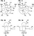
FIG. 2A , a cross-sectional view of a portion of the beverage dispenser shown inFIG. 2 taken along line 2A-2A is depicted which includes acam 130 and ahot beverage pod 132. The hotbeverage dispensing head 114 may operate in any orientation. In this example, the hotbeverage dispensing head 114 is moved in position such that a hot beverage is dispensed from thepod beverage dispenser 100. Thehot beverage pod 132 can include a brewable material such as coffee grounds, tea leaves, or the like or thehot beverage pod 132 can include a hot beverage concentrate such as a liquid concentrate, a powder, freeze-dried crystals, or the like. The hot beverage concentrate may be made from a previously brewed beverage or brewed beverage concentrate. Hot water or other hot fluids may be dispensed from the hotbeverage dispensing head 114 through thehot beverage pod 132 to dispense a hot beverage, such as, but not limited to, a coffee, tea, etc. - Referring to
FIG. 3A , a cross-sectional view of a portion of the beverage dispenser shown inFIG. 3 taken along line 3A-3A is depicted which includes thecam 130 and acold beverage pod 134. In this example, the coldbeverage dispensing head 116 is in position such that a cold beverage is dispensed from thepod beverage dispenser 100. The coldbeverage dispensing head 116 may operate in any orientation. Thecold beverage pod 134 can include liquid concentrate or powder for forming a non-carbonated or carbonated beverage. Cold water, cold carbonated water, or other cold fluids may be dispensed from the coldbeverage dispensing head 116 through thecold beverage pod 134 to dispense a cold beverage, such as, but not limited to a juice, a tea, a soft drink, etc. - The
cam 130 is a rotating or sliding piece in a mechanical linkage used to transform rotary motion into linear motion or vice-versa. In this example, thecam 130 is used to translate the dispensinghead 114 towards and away from the pods. For example, upon rotating thecam 130 180 degrees, the dispensinghead 114 is lowered onto the pod at the dispensing station with sufficient force so as to form a sealing engagement between the dispensinghead 114 and the pod. - A cam motor may drive the
cam 130. The cam motor may be a conventional AC motor or a similar type of device. In alternative designs, the cam can be replaced with other mechanisms that provide linear actuation, such as a pneumatic cylinder or a rack and pinion mechanism. - The
beverage dispenser 100 may be configured to identify the type ofpod 122 being inserted into theturret assembly 104. The configuration can include detecting a machine readable element on each pod, such as, but not limited to, a radiofrequency identification tag (RFID), that corresponds to a reading device in thebeverage dispenser 100. In other examples the recognition system can includes barcodes, magnetic strips, optical recognition, microchips, and the like, including combinations thereof. In certain examples, the method for recognition may include physical obstructions, such as, but not limited to, voids, bumps, ridges, holes, recesses, protrusions, and the like, including combinations thereof. - In certain examples, upon insertion of the
hot beverage pod 132 into theturret assembly 104, the hotbeverage dispensing head 114 would automatically index to the dispensingstation 106. Likewise, upon insertion of thecold beverage pod 134 into theturret assembly 104, the coldbeverage dispensing head 116 would automatically index to the dispensingstation 106. In this example, the user does not have to specify the type ofpod 122 being inserted in theturret assembly 104 of thebeverage dispenser 100 because all of the information regarding the pod type, ingredients therein, number of compartments within the pod, etc. will be recognized by the identification system. Thepod 122 can be arranged and configured to be used within any type of pod beverage dispenser. - Referring to
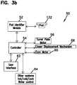
FIG. 3b , anexample control system 50 for thepod beverage dispenser 100 is illustrated. Once a consumer places thehot beverage pod 132 into theturret assembly 104, apod identifier module 52 can detect the type of beverage pod inserted in theturret assembly 104. As described above, thepod identifier module 52 may be a machine reader for reading one or more of an RFID tag, barcode, magnetic strip, optical symbol, microchip, and the like, such as, but not limited to, an RFID reader, a barcode reader, a magnetic strip reader, an optical sensor, or a microchip interface. Anelectronic controller 54 may monitor and control the operation of thepod beverage dispenser 100 as a whole and each of the components therein. Theelectronic controller 54 may be a microcontroller or a similar type of device. Once the identification of thehot beverage pod 132 is made, theelectronic controller 54 may operate aturret plate motor 56, alinear displacement mechanism 58, and acam motor 60. The correct pod compartment of theturret plate 118 may rotate into place and thehot beverage pod 132 may be dropped into thecorrect turret aperture 120 for theturret assembly 104. - In certain examples, the
electronic controller 54 may be integrated with auser interface 62. In some embodiments, theuser interface 62 may receive input from a consumer to identify the type of beverage pod inserted in theturret assembly 104. For example, theuser interface 62 may receive selections of a pod on a user input screen or receive product code information provided on the pod packaging. In other examples, theelectronic controller 54 may be integrated with other systems 64 (e.g. hot/cold/carbonated/ water controls) for automatic dispensing. - Referring to
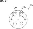
FIG. 4 , an example alternative embodiment of aturret assembly 104a arranged and configured with two dispensing stations is illustrated. It is understood that the configuration of the two dispensing stations may vary in other embodiments. - In one example, the
turret assembly 104a includes afirst dispensing station 136 and asecond dispensing station 138 for dispensing from a hot beverage dispensing head 114a and a coldbeverage dispensing head 116a respectively. In other words, thefirst dispensing station 136 is dedicated to coffee or any hot beverage and thesecond dispensing station 138 is dedicated to any cold beverage. The hot beverage dispensing head 114a is positioned above thefirst dispensing station 136 and the coldbeverage dispensing head 116a is positioned above thesecond dispensing station 138. Upon insertion of a hot beverage pod 132a theturret assembly 104a automatically indexes the hot beverage pod 132a to thefirst dispensing station 136 by rotating theturret plate 118 90°, for example. Similarly, upon insertion of a cold beverage pod 134a into theturret assembly 104a, theturret assembly 104a automatically indexes the cold beverage pod 134a to thesecond dispensing station 138 by rotating theturret plate 118 180°, for example. As described above, thecontrol system 50 and a method for recognizing the type of pod inserted in theturret assembly 104a can be used. With two dispensing stations, thelinear displacement mechanism 58 may not be present because the dispensingheads 114a, 116a may be laterally fixed over their respective dispensingstations - Referring to
FIG. 5 , a schematic of an example fluidic diagram 140 is illustrated for dispensing a beverage from thecold beverage pod 134. - The example fluidic diagram 140 includes a first diluent stream 142, a
macro-ingredient stream 144, amixing device 146, amixed stream 148 exiting themixing device 146, a second diluent stream 150 (e.g., ingredient transfer medium) entering thepod 122, and aningredients stream 152 exiting thepod 122. - The
macro-ingredient stream 144 typically has a viscosity and density much different from common diluents and must be thoroughly mixed to prevent stratification. In some embodiments, themacro-ingredient stream 144 may be a nutritive sweetener, such as, high fructose corn syrup (HFCS), liquid sucrose, an inverted sugar, or other such sweeteners. In some embodiments, themacro-ingredient stream 144 may be a non-sweetener beverage ingredient. Themixing device 146 can be a conventional dispensing nozzle well known to those in the art. Themixed stream 148 contains a mixture of the first diluent and themacro-ingredient stream 144 that is dispensed into acup 154. The first diluent may be water, carbonated water, or other beverage diluents. - In one example, carbon dioxide (CO2) gas is routed to the
pod 122 to act as theingredient transfer medium 150 to transfer the ingredients out of thepod 122 into thecup 154. The ingredients in thepod 122 can have a viscosity and density similarly to common diluents and may not be prone to stratification. In some embodiments, the ingredients in thepod 122 may include one or more beverage micro-ingredient. In some embodiments, the ingredients may be un-sweetened beverage ingredients, such as an unsweetened beverage micro-ingredient. Themixed stream 148 and the ingredients stream 152 dispensing in thecup 154 are parallel to each other. - In other embodiments, the
mixed stream 148 and the ingredients stream 152 may be in one stream. In some examples, theingredient transfer medium 150 may not be CO2. In such examples, themixed stream 148 of diluent and themacro-ingredient stream 144 are routed through thepod 122 and becomes theingredient transfer medium 150 to dispense the ingredients from thepod 122. - In still other embodiments, the fluidic diagram 140 may include a secondary diluent stream that branches off the diluent stream 142 upstream or downstream of the
mixing device 146. The secondary diluent stream may be used as theingredient transfer medium 150. - Referring to
FIG. 5a , another example of an example fluidic diagram 140a is illustrated for dispensing a beverage. In the illustration, the fluidic diagram 140a includes apod 122a, amacro ingredient source 141a, a CO2 source 143 a, a H2O source 145a, and otherbeverage ingredient sources 147a. In the depicted illustration, ingredients from thepod 122a are being dispensed into acup 154a. The CO2 source 143a has a carbonator 149a that is used to generate carbonated water that is dispensed into thecup 154a. In some embodiments, the CO2 source 143a may have a removable CO2 cylinder. In one example, the H2O source 145a includes aheater 151a for generating hot water that can be dispensed in thecup 154a. In some embodiments, thewater source 145a may include a removable water reservoir or a water supply line. Water that does not undergo heating from theheater 151a may also be dispensed into thecup 154a. In certain examples,other ingredient sources 147a (e.g., juice, dairy, milk, yogurt, etc.) may be dispensed to thecup 154a. - Ingredients that can be used in pods of the
pod beverage dispenser 100 include: traditional beverage syrup (nutritive or non-nutritive sweetened), un-sweetened beverage concentrate, un-sweetened beverage micro-ingredient, un-sweetened acid and acid-degradable beverage flavor components, non-nutritive or high-intensity sweetener can be included in the acid-degradable flavor component. It is to be appreciated that other ingredient scenarios may be possible. - Various dispensing scenarios can be accomplished using the beverage dispensers and pods described herein. For example, one or more of the dispensing mechanisms described herein can be used to dispense either hot beverages (e.g., coffee, tea) or cold beverages (e.g., carbonated soft drinks). The pods used to accomplish both the hot and cold beverages can be similar in external geometries to allow for ease in the insertion into the beverage dispensers.
- Further, the pods can be arranged in both serial (i.e., co-linearly) and parallel (i.e., perpendicularly or radially) configurations to accomplish different dispensing scenarios, as needed. In addition, add-on flavors can be arranged in series or parallel to increase the number of beverage dispensing choices. In addition, the pods can be used to deliver a macro ingredient or syrup, which is a beverage ingredient with a reconstitution ratio might be somewhere between 06:01 to 10:01.
- Referring to
FIG. 6 , one example embodiment of thepod 122 is illustrated. Thepod 122 can include acup 156, aninsert 158, afilter layer 160, abottom seal 162, and atop seal 164. Further details about an example pod are disclosed atU.S. Patent Publication No. 2005/0095158 A1 . - The
cup 156 can be made out of a conventional thermoplastic such as polystyrene or polyethylene. It will be appreciated that thecup 156 can be made out of metal, such as, but not limited stainless steel, or similar types of substantially noncorrosive materials. - The
insert 158 encloses the top of thecup 156. Theinsert 158 may be made out of a thermoplastic or a similar material as is used for thecup 156. Theinsert 158 defines a plurality ofapertures 112 such that in use fluid passes over and through theapertures 112 into thecup 156. In other examples, the pod may not include theinsert 158 such that fluid flows directly into thecup 156 from the top of thepod 122. - The
top seal 164 encloses thecup 156 to provide an airtight seal for the ingredients contained within thepod 122. Thetop seal 164 can be made out of a foil or similar type of substantially airtight material. - The
bottom seal 162 is arranged and configured to enclose the bottom end of thecup 156. Thebottom seal 162 may include thefilter layer 160. Thebottom seal 162 can be made out of foil or similar material as is used for thetop seal 164. The top andbottom seals pod 122 in a substantially airtight manner for freshness purposes. Thefilter layer 160 may be made out of a paper filter material or similar types of material. In other examples, thepod 122 may not include thefilter layer 160. - The
pod 122 is arranged and configured with various storage compartments that can each include an ingredient. The storage compartments of thepod 122 are constructed in a series configuration. In a series configuration (seeFIGs. 7-8 ), the ingredients are stored in the pod so that the diluent generally dilutes each ingredient sequentially. Other configurations are possible, such as pods having both parallel and series configurations. - The
pod 122 may be filled with various combinations of ingredients. A few of the various ingredients used in thepods 122 are macro ingredients, such as non-nutritive sweetener or nutritive sweetener (i.e. sugar syrup or HFCS). The macro-ingredient can have a reconstitution ratio of less than 10:1. In some examples, the macro-ingredient may have a reconstitution ratio between about 3:1 to about 6:1. Thepods 122 can also include micro ingredients, such as, natural and artificial flavors, natural an artificial colors, and acid and non-acid components of flavoring. The micro-ingredient can have a reconstitution ratio greater than or equal to 10:1. These ingredients may include acids, flavors and high-intensity or non-nutritive sweeteners. It will be appreciated that any number of ingredient combinations can be used inpods 122 along with multiple compartment configurations. - Referring to
FIG. 7 , anexample pod 222 is shown with ingredient storage compartments arranged and configured in series. Theexample pod 222 is a multi-ingredient pod that can be arranged co-linearly with a diluent flow so as to discharge the ingredients contained in the compartments sequentially. In the illustrated example, there is a firstingredient storage compartment 224, a secondstorage ingredient compartment 226, and a thirdingredient storage compartment 228 stacked together one on top of the other. It will be appreciated that thepod 222 can include any number of ingredient storage compartments. - In one example, the
example pod 222 can be a cold beverage type pod having ingredient storage compartments 224, 226, 228. The ingredient storage compartments 224, 226, 228 can include macro-ingredients, such as non-nutritive sweetener or nutritive sweetener (i.e. sugar syrup or HFCS). The ingredient storage compartments 224, 226, 228 can also include micro ingredients, such as, natural and artificial flavors, natural an artificial colors, and acid and non-acid components of flavoring. A diluent such as CO2 or water can be used to transfer the ingredients out of thepod 222. In other examples, the diluent may include a sweetener, acid flavor components, or non-acid flavor components. - In one example, the
example pod 222 can include an add-onflavor pod 322. The add-onflavor pod 322 is added serially to theexample pod 222. The add-onflavor pod 322 can include flavors such as, but not limited to, cherry, vanilla, or raspberry. The add-on flavor can be mixed with the main ingredients in thepod 222 to create a flavored beverage. - Referring to
FIG. 8 , theexample pod 222 and the add-onflavor pod 322 are illustrated in theturret plate 118. Theturret plate 118 may include a number ofapertures 120 therein. Theapertures 120 may be sized to accommodate thepod 122. An example turret assembly and turret plate is disclosed atU.S. Patent Publication No. 2005/0095158 A1 . As shown, theexample pod 222 includes two ingredient storage compartments A, B. The ingredient storage compartments A, B are separated by therupturable membrane 186. Therupturable membrane 186 separates the ingredients within each compartment A, B until dispensing. It will be appreciated that thepod 222 may include any number of ingredient storage compartments. In one example, the add-onflavor pod 322 can be inserted in theturret plate 118 first followed by thepod 222 for a carbonated soft drink. In such situations, the add-onflavor pod 322 and thepod 222 are stacked one on top of the other.Rupturable membranes 186 are used to seal the inlet and outlet ports of thepod 222 and inlet and outlet ports of the add-onflavor pod 322. When a dispensing head is placed on thepod 222, pressure from a diluent stream causes therupturable membranes 186 of thepod 222 and add-onflavor pod 322 to break allowing the ingredients in eachpod - In other examples, the add-on
flavor pod 322 may not be included. The add-on flavor may be included in thepod 222 as a separate ingredient storage compartment. Thus, it is not necessary to include multiple pods that are stacked together in series because a single pod can be configured to include a multiple number of ingredient storage compartments. - When the cold
beverage dispensing head 116 lowers onto thepod 222, the tube containing the transfer medium (i.e. diluent) creates a seal against a first inlet port of thepod 222. The downward force generated by the coldbeverage dispensing head 116 also seals a first outlet port of thepod 222 to an inlet port of the add-onflavor pod 322. The add-onflavor pod 322 can become an additional internal chamber associated with thepod 222 and can function as such during dispensing.
Claims (15)
- A cartridge (222) for use in a beverage dispenser (100),characterized in that the cartridge (222) comprises:a plurality of storage compartments (224, 226, 228) stacked in series within an interior of the cartridge (222), each of the plurality of storage compartments (222) including: an inlet port, an outlet port opposite the inlet port, an ingredient contained between the inlet and outlet ports, and a seal (186) covering the inlet and outlet ports;wherein the cartridge (222) is configured to allow a transfer medium to rupture the seal (186) of each of the storage compartments (224, 226, 228) and to enter the inlet port to dilute the ingredient in each of the plurality of storage compartments (224, 226, 228) in series and to discharge the diluted ingredients out of the cartridge (222).
- The cartridge (222) of claim 1, wherein:the seal (186) is a rupturable membrane; orthe seal (186) is a shuttle valve.
- The cartridge (222) of claim 1, wherein the transfer medium is a diluent stream;
preferably wherein a flowing beverage formed by interaction of the diluent stream with the ingredient contained in each of the plurality of storage compartments (224, 226, 228) flows through to the outlet port. - The cartridge (222) of claim 1, further comprising an add-on cartridge (322) in series; and/or
wherein the ingredient in one of the plurality of storage compartments (224, 226, 228) is selected from a group consisting of: high fructose corn syrup, non-nutritive sweetener, artificial flavors, acids, natural flavors, and mixtures thereof; and/or
wherein the plurality of storage compartments (224, 226, 228) are separated by internal dividers. - The cartridge (222) of claim 1, further comprising an identification signal to identify a type of beverage being dispensed;
wherein the identification signal preferably includes one or more of a RFID tag, barcodes, magnetic strips, optical recognition, microchips, and combinations thereof. - A beverage dispenser (100) comprising:a cartridge (222) according to claim 1, wherein the plurality of storage compartments (224, 226, 228) are stacked on top of one another;a turret (104) including a first station (106) for dispensing the cartridge (222);a first dispensing head (114); anda second dispensing head (116) adjacent to the first dispensing head (114);wherein the first and second dispensing heads (114, 116) are arranged and configured to move laterally such that one of the first and second dispensing heads (114, 116) is positioned over the first dispensing station (106) for dispensing therefrom.
- The beverage dispenser (100) of claim 6, further comprising a second dispensing station (138).
- The beverage (100) dispenser of claim 7, wherein the first dispensing head (114a) is positioned over the first dispensing station (136) for dispensing therefrom, and the second dispensing head (116a) is positioned over the second dispensing station (138) for dispensing therefrom.
- The beverage dispenser (100) of claim 7, wherein the first dispensing head (114) dispenses hot beverages and the second dispensing head (116) dispenses cold beverages.
- The beverage dispenser (100) of claim 9, wherein:the hot beverages are coffee or tea; and/orthe cold beverages are carbonated soft drinks.
- The beverage dispenser (100) of claim 7, wherein the cartridge (222) further comprises an identification signal to identify a type of cartridge (222) being dispensed, such that the turret (104) indexes the cartridge (222) to the corresponding first or the second dispensing station (136, 138); and
wherein the identification signal preferably includes one or more of a RFID tag, barcodes, magnetic strips, optical recognition, microchips, and combinations thereof. - The beverage dispenser (100) of claim 6, further comprising a mixing device (146), a first diluent stream (142), and a nutritive sweetener stream (144), wherein the first diluent stream (142) and the nutritive sweetener stream (144) are mixed together in the mixing device (146) forming a transfer medium.
- The beverage dispenser (100) of claim 12, wherein:the mixing device (146) is a dispensing nozzle; and/orthe transfer medium is used to transfer the ingredient within each of the plurality of storage compartments (224, 226, 228) out of the cartridge (222) thereof to form a beverage.
- The beverage dispenser (100) of claim 12, further comprising a second diluent stream (150) branching off the first diluent stream (142), wherein the second diluent stream (142) transfers the ingredient within each of the plurality of storage compartments (224, 226, 228) out of the cartridge (222) into a cup;
wherein the transfer medium preferably mixes with the second diluent stream (150) in the cup to form a beverage. - The beverage dispenser (100) of claim 6, wherein the storage compartments (224, 226, 228) of the cartridge (222) are positioned both in series and in parallel; and/or
further comprising a plurality of cartridges (222) positioned in series.
Applications Claiming Priority (2)
| Application Number | Priority Date | Filing Date | Title |
|---|---|---|---|
| US201361920158P | 2013-12-23 | 2013-12-23 | |
| PCT/US2014/071928WO2015100250A1 (en) | 2013-12-23 | 2014-12-22 | Dispensing ingredients from a beverage cartridge |
Publications (3)
| Publication Number | Publication Date |
|---|---|
| EP3086693A1 EP3086693A1 (en) | 2016-11-02 |
| EP3086693A4 EP3086693A4 (en) | 2017-10-18 |
| EP3086693B1true EP3086693B1 (en) | 2021-02-17 |
Family
ID=53479619
Family Applications (1)
| Application Number | Title | Priority Date | Filing Date |
|---|---|---|---|
| EP14874578.9AActiveEP3086693B1 (en) | 2013-12-23 | 2014-12-22 | Dispensing ingredients from a beverage cartridge |
Country Status (3)
| Country | Link |
|---|---|
| US (1) | US20160318689A1 (en) |
| EP (1) | EP3086693B1 (en) |
| WO (1) | WO2015100250A1 (en) |
Families Citing this family (26)
| Publication number | Priority date | Publication date | Assignee | Title |
|---|---|---|---|---|
| EP2865301A1 (en)* | 2013-10-28 | 2015-04-29 | Nestec S.A. | Beverage dispensing system, method for providing a multi-layered beverage, and ingredients container for use thereof |
| US9883766B2 (en)* | 2015-11-20 | 2018-02-06 | Pepsico, Inc. | Beverage dispenser systems and methods |
| CA3041722A1 (en) | 2016-11-09 | 2018-05-17 | Pepsico, Inc. | Carbonated beverage makers, methods, and systems |
| NL2018745B1 (en)* | 2017-04-19 | 2018-10-29 | Apiqe Holdings Llc | System and method for the preparation of hot and cold beverages |
| US10470605B2 (en) | 2017-04-21 | 2019-11-12 | Whirlpool Corporation | Single-serving beverage machine with high-capacity and compact cooling-carbonation system |
| WO2019079385A1 (en)* | 2017-10-17 | 2019-04-25 | The Coca-Cola Company | Flexible high speed filling line for personalized beverage package mixes with dispensing needles |
| ES2900060T3 (en) | 2017-11-29 | 2022-03-15 | Goglio Spa | One capsule for soluble or extractable products |
| US11781808B2 (en)* | 2019-04-09 | 2023-10-10 | Coldsnap, Corp. | Brewing and cooling a beverage |
| US11647860B1 (en) | 2022-05-13 | 2023-05-16 | Sharkninja Operating Llc | Flavored beverage carbonation system |
| US12213617B2 (en) | 2022-05-13 | 2025-02-04 | Sharkninja Operating Llc | Flavored beverage carbonation process |
| AU2022457789A1 (en) | 2022-05-13 | 2024-11-21 | Sharkninja Operating Llc | Agitator for a carbonation system |
| US12096880B2 (en) | 2022-05-13 | 2024-09-24 | Sharkninja Operating Llc | Flavorant for beverage carbonation system |
| US11751585B1 (en) | 2022-05-13 | 2023-09-12 | Sharkninja Operating Llc | Flavored beverage carbonation system |
| US12005404B2 (en) | 2022-08-22 | 2024-06-11 | Sharkninja Operating Llc | Beverage carbonation system flow control |
| US20240066483A1 (en)* | 2022-08-31 | 2024-02-29 | Sharkninja Operating Llc | Additive containers |
| US11634314B1 (en) | 2022-11-17 | 2023-04-25 | Sharkninja Operating Llc | Dosing accuracy |
| US11745996B1 (en) | 2022-11-17 | 2023-09-05 | Sharkninja Operating Llc | Ingredient containers for use with beverage dispensers |
| US12084334B2 (en) | 2022-11-17 | 2024-09-10 | Sharkninja Operating Llc | Ingredient container |
| US11738988B1 (en) | 2022-11-17 | 2023-08-29 | Sharkninja Operating Llc | Ingredient container valve control |
| US12103840B2 (en) | 2022-11-17 | 2024-10-01 | Sharkninja Operating Llc | Ingredient container with sealing valve |
| USD1092208S1 (en) | 2022-12-23 | 2025-09-09 | Sharkninja Operating Llc | Cap of ingredient container |
| USD1091308S1 (en) | 2022-12-23 | 2025-09-02 | Sharkninja Operating Llc | Ingredient container |
| US11871867B1 (en) | 2023-03-22 | 2024-01-16 | Sharkninja Operating Llc | Additive container with bottom cover |
| US12116257B1 (en) | 2023-03-22 | 2024-10-15 | Sharkninja Operating Llc | Adapter for beverage dispenser |
| US11925287B1 (en) | 2023-03-22 | 2024-03-12 | Sharkninja Operating Llc | Additive container with inlet tube |
| US12005408B1 (en) | 2023-04-14 | 2024-06-11 | Sharkninja Operating Llc | Mixing funnel |
Citations (4)
| Publication number | Priority date | Publication date | Assignee | Title |
|---|---|---|---|---|
| EP2100824A1 (en)* | 2008-03-12 | 2009-09-16 | Nestec S.A. | Capsule with flow control and filtering member |
| US20100159077A1 (en)* | 2008-12-18 | 2010-06-24 | Whirlpool Corporation | Liquid flow control and beverage preparation apparatuses, methods and systems |
| EP2510805A2 (en)* | 2008-01-29 | 2012-10-17 | Koninklijke Douwe Egberts B.V. | System, method and capsule for preparing a beverage |
| WO2013066178A1 (en)* | 2011-11-04 | 2013-05-10 | Koninklijke Douwe Egberts B.V. | Form-retaining pad for preparing a beverage suitable for consumption, assembly of a beverage preparation machine comprising a pad holder and such a form-retaining pad, a method of manufacturing such a form-retaining pad, pre-form stiffening body for use in such a method, a method for preparing a beverage suitable for consumption using such a form-retaining pad or such an assembly and a kit of parts comprising a plurality of such form-retaining pads |
Family Cites Families (16)
| Publication number | Priority date | Publication date | Assignee | Title |
|---|---|---|---|---|
| US3713780A (en)* | 1971-02-01 | 1973-01-30 | Becton Dickinson Co | Apparatus for chemical testing |
| US5243164A (en)* | 1990-12-14 | 1993-09-07 | Gee Associates | Beverage maker |
| US6740345B2 (en)* | 2000-12-22 | 2004-05-25 | Edward Zhihua Cai | Beverage making cartridge |
| US20050095158A1 (en) | 2002-02-07 | 2005-05-05 | The Coca-Cola Company | Coffee and tea dispenser with removable pod turret wheel |
| US7196044B2 (en) | 2003-07-02 | 2007-03-27 | Ecolab, Inc. | Warewashing composition for use in automatic dishwashing machines, comprising a zinc ion and aluminum ion corrosion inhibitor |
| DE102004002004A1 (en)* | 2004-01-14 | 2005-08-11 | Schifferle, René | Coffee machine for brewing coffee powder packaged in a capsule |
| NL1028133C2 (en)* | 2005-01-27 | 2006-07-31 | Sara Lee De Nv | Method and device for preparing a drink suitable for consumption. |
| US20080023349A1 (en)* | 2005-08-04 | 2008-01-31 | Balazik Ronald F | Internal Drink Mix System |
| US8322271B2 (en)* | 2007-07-02 | 2012-12-04 | Brewl Technologies, Inc. | Infusible material capsule for brewing a beverage |
| IT1390883B1 (en)* | 2008-07-31 | 2011-10-19 | Cometto | GROUP OF DRINKS FOR DRINKS |
| EP2230195B1 (en)* | 2009-03-19 | 2018-04-25 | Nestec S.A. | Capsule with filtering insert for preparing a coffee beverage |
| DK2687446T3 (en)* | 2009-04-15 | 2015-08-24 | Luna Technology Systems Lts Gmbh | A process for preparing a capsule for an extraction material |
| EP2865613B1 (en)* | 2009-06-17 | 2017-09-06 | Koninklijke Douwe Egberts B.V. | System, method and capsule for preparing a beverage |
| US20130189400A1 (en)* | 2011-09-21 | 2013-07-25 | Providence Enterprise, Llc | Single serve beverage dispensing system including an ionizer |
| ES2613854T3 (en)* | 2012-04-17 | 2017-05-26 | Sarong Societa' Per Azioni | Capsule and dispensing machine for drinks |
| EP2892826A1 (en)* | 2012-09-05 | 2015-07-15 | Koninklijke Philips N.V. | Capsule for the preparation of beverages, device and method |
- 2014
- 2014-12-22EPEP14874578.9Apatent/EP3086693B1/enactiveActive
- 2014-12-22WOPCT/US2014/071928patent/WO2015100250A1/enactiveApplication Filing
- 2014-12-22USUS15/107,553patent/US20160318689A1/ennot_activeAbandoned
Patent Citations (5)
| Publication number | Priority date | Publication date | Assignee | Title |
|---|---|---|---|---|
| EP2510805A2 (en)* | 2008-01-29 | 2012-10-17 | Koninklijke Douwe Egberts B.V. | System, method and capsule for preparing a beverage |
| EP2100824A1 (en)* | 2008-03-12 | 2009-09-16 | Nestec S.A. | Capsule with flow control and filtering member |
| US20100159077A1 (en)* | 2008-12-18 | 2010-06-24 | Whirlpool Corporation | Liquid flow control and beverage preparation apparatuses, methods and systems |
| WO2013066178A1 (en)* | 2011-11-04 | 2013-05-10 | Koninklijke Douwe Egberts B.V. | Form-retaining pad for preparing a beverage suitable for consumption, assembly of a beverage preparation machine comprising a pad holder and such a form-retaining pad, a method of manufacturing such a form-retaining pad, pre-form stiffening body for use in such a method, a method for preparing a beverage suitable for consumption using such a form-retaining pad or such an assembly and a kit of parts comprising a plurality of such form-retaining pads |
| ES2608669T3 (en)* | 2011-11-04 | 2017-04-12 | Koninklijke Douwe Egberts B.V. | Capsule with shape memory for the preparation of a beverage, set of a machine for the preparation of beverages comprising a capsule holder and said capsule with shape memory and related procedures |
Also Published As
| Publication number | Publication date |
|---|---|
| WO2015100250A1 (en) | 2015-07-02 |
| EP3086693A4 (en) | 2017-10-18 |
| EP3086693A1 (en) | 2016-11-02 |
| US20160318689A1 (en) | 2016-11-03 |
Similar Documents
| Publication | Publication Date | Title |
|---|---|---|
| EP3086693B1 (en) | Dispensing ingredients from a beverage cartridge | |
| US6786134B2 (en) | Coffee and tea dispenser | |
| EP1893063B1 (en) | Coffee and tea dispenser | |
| US11603304B2 (en) | Pod assembly for beverage machine | |
| US20050095158A1 (en) | Coffee and tea dispenser with removable pod turret wheel | |
| US9161654B2 (en) | Select serving and flavored sparkling beverage maker system | |
| US20200345170A1 (en) | Food or beverage dispensing device and method for preparing a food or a beverage from one or a plurality of containers | |
| US12245717B2 (en) | System for multi-ingredient beverage preparation from various container types | |
| AU2013217333A1 (en) | A beverage preparation system, a coded insert and methods of use thereof | |
| CN107072430A (en) | System for preparing food or drink from sachets | |
| EP3288433B1 (en) | Vacuum side air vent | |
| EP4376680B1 (en) | Beverage preparation system |
Legal Events
| Date | Code | Title | Description |
|---|---|---|---|
| PUAI | Public reference made under article 153(3) epc to a published international application that has entered the european phase | Free format text:ORIGINAL CODE: 0009012 | |
| 17P | Request for examination filed | Effective date:20160706 | |
| AK | Designated contracting states | Kind code of ref document:A1 Designated state(s):AL AT BE BG CH CY CZ DE DK EE ES FI FR GB GR HR HU IE IS IT LI LT LU LV MC MK MT NL NO PL PT RO RS SE SI SK SM TR | |
| AX | Request for extension of the european patent | Extension state:BA ME | |
| RIN1 | Information on inventor provided before grant (corrected) | Inventor name:GREEN, C., BRAD Inventor name:RUDICK, ARTHUR, G. | |
| DAX | Request for extension of the european patent (deleted) | ||
| A4 | Supplementary search report drawn up and despatched | Effective date:20170914 | |
| RIC1 | Information provided on ipc code assigned before grant | Ipc:B65D 25/04 20060101ALI20170908BHEP Ipc:B65D 81/32 20060101ALI20170908BHEP Ipc:A47J 31/46 20060101ALI20170908BHEP Ipc:B65D 85/804 20060101ALI20170908BHEP Ipc:A47J 31/40 20060101ALI20170908BHEP Ipc:A47J 31/50 20060101ALI20170908BHEP Ipc:A47J 31/36 20060101ALI20170908BHEP Ipc:A47J 31/44 20060101ALI20170908BHEP Ipc:A47J 31/24 20060101AFI20170908BHEP | |
| GRAP | Despatch of communication of intention to grant a patent | Free format text:ORIGINAL CODE: EPIDOSNIGR1 | |
| STAA | Information on the status of an ep patent application or granted ep patent | Free format text:STATUS: GRANT OF PATENT IS INTENDED | |
| INTG | Intention to grant announced | Effective date:20200204 | |
| GRAJ | Information related to disapproval of communication of intention to grant by the applicant or resumption of examination proceedings by the epo deleted | Free format text:ORIGINAL CODE: EPIDOSDIGR1 | |
| STAA | Information on the status of an ep patent application or granted ep patent | Free format text:STATUS: REQUEST FOR EXAMINATION WAS MADE | |
| INTC | Intention to grant announced (deleted) | ||
| GRAP | Despatch of communication of intention to grant a patent | Free format text:ORIGINAL CODE: EPIDOSNIGR1 | |
| STAA | Information on the status of an ep patent application or granted ep patent | Free format text:STATUS: GRANT OF PATENT IS INTENDED | |
| INTG | Intention to grant announced | Effective date:20200929 | |
| GRAS | Grant fee paid | Free format text:ORIGINAL CODE: EPIDOSNIGR3 | |
| GRAA | (expected) grant | Free format text:ORIGINAL CODE: 0009210 | |
| STAA | Information on the status of an ep patent application or granted ep patent | Free format text:STATUS: THE PATENT HAS BEEN GRANTED | |
| AK | Designated contracting states | Kind code of ref document:B1 Designated state(s):AL AT BE BG CH CY CZ DE DK EE ES FI FR GB GR HR HU IE IS IT LI LT LU LV MC MK MT NL NO PL PT RO RS SE SI SK SM TR | |
| REG | Reference to a national code | Ref country code:GB Ref legal event code:FG4D | |
| REG | Reference to a national code | Ref country code:CH Ref legal event code:EP | |
| REG | Reference to a national code | Ref country code:DE Ref legal event code:R096 Ref document number:602014074990 Country of ref document:DE | |
| REG | Reference to a national code | Ref country code:AT Ref legal event code:REF Ref document number:1360313 Country of ref document:AT Kind code of ref document:T Effective date:20210315 | |
| REG | Reference to a national code | Ref country code:IE Ref legal event code:FG4D | |
| REG | Reference to a national code | Ref country code:LT Ref legal event code:MG9D | |
| REG | Reference to a national code | Ref country code:NL Ref legal event code:MP Effective date:20210217 | |
| PG25 | Lapsed in a contracting state [announced via postgrant information from national office to epo] | Ref country code:LT Free format text:LAPSE BECAUSE OF FAILURE TO SUBMIT A TRANSLATION OF THE DESCRIPTION OR TO PAY THE FEE WITHIN THE PRESCRIBED TIME-LIMIT Effective date:20210217 Ref country code:PT Free format text:LAPSE BECAUSE OF FAILURE TO SUBMIT A TRANSLATION OF THE DESCRIPTION OR TO PAY THE FEE WITHIN THE PRESCRIBED TIME-LIMIT Effective date:20210617 Ref country code:FI Free format text:LAPSE BECAUSE OF FAILURE TO SUBMIT A TRANSLATION OF THE DESCRIPTION OR TO PAY THE FEE WITHIN THE PRESCRIBED TIME-LIMIT Effective date:20210217 Ref country code:GR Free format text:LAPSE BECAUSE OF FAILURE TO SUBMIT A TRANSLATION OF THE DESCRIPTION OR TO PAY THE FEE WITHIN THE PRESCRIBED TIME-LIMIT Effective date:20210518 Ref country code:HR Free format text:LAPSE BECAUSE OF FAILURE TO SUBMIT A TRANSLATION OF THE DESCRIPTION OR TO PAY THE FEE WITHIN THE PRESCRIBED TIME-LIMIT Effective date:20210217 Ref country code:BG Free format text:LAPSE BECAUSE OF FAILURE TO SUBMIT A TRANSLATION OF THE DESCRIPTION OR TO PAY THE FEE WITHIN THE PRESCRIBED TIME-LIMIT Effective date:20210517 Ref country code:NO Free format text:LAPSE BECAUSE OF FAILURE TO SUBMIT A TRANSLATION OF THE DESCRIPTION OR TO PAY THE FEE WITHIN THE PRESCRIBED TIME-LIMIT Effective date:20210517 | |
| REG | Reference to a national code | Ref country code:AT Ref legal event code:MK05 Ref document number:1360313 Country of ref document:AT Kind code of ref document:T Effective date:20210217 | |
| PG25 | Lapsed in a contracting state [announced via postgrant information from national office to epo] | Ref country code:SE Free format text:LAPSE BECAUSE OF FAILURE TO SUBMIT A TRANSLATION OF THE DESCRIPTION OR TO PAY THE FEE WITHIN THE PRESCRIBED TIME-LIMIT Effective date:20210217 Ref country code:NL Free format text:LAPSE BECAUSE OF FAILURE TO SUBMIT A TRANSLATION OF THE DESCRIPTION OR TO PAY THE FEE WITHIN THE PRESCRIBED TIME-LIMIT Effective date:20210217 Ref country code:PL Free format text:LAPSE BECAUSE OF FAILURE TO SUBMIT A TRANSLATION OF THE DESCRIPTION OR TO PAY THE FEE WITHIN THE PRESCRIBED TIME-LIMIT Effective date:20210217 Ref country code:LV Free format text:LAPSE BECAUSE OF FAILURE TO SUBMIT A TRANSLATION OF THE DESCRIPTION OR TO PAY THE FEE WITHIN THE PRESCRIBED TIME-LIMIT Effective date:20210217 Ref country code:RS Free format text:LAPSE BECAUSE OF FAILURE TO SUBMIT A TRANSLATION OF THE DESCRIPTION OR TO PAY THE FEE WITHIN THE PRESCRIBED TIME-LIMIT Effective date:20210217 | |
| PG25 | Lapsed in a contracting state [announced via postgrant information from national office to epo] | Ref country code:IS Free format text:LAPSE BECAUSE OF FAILURE TO SUBMIT A TRANSLATION OF THE DESCRIPTION OR TO PAY THE FEE WITHIN THE PRESCRIBED TIME-LIMIT Effective date:20210617 | |
| PG25 | Lapsed in a contracting state [announced via postgrant information from national office to epo] | Ref country code:SM Free format text:LAPSE BECAUSE OF FAILURE TO SUBMIT A TRANSLATION OF THE DESCRIPTION OR TO PAY THE FEE WITHIN THE PRESCRIBED TIME-LIMIT Effective date:20210217 Ref country code:AT Free format text:LAPSE BECAUSE OF FAILURE TO SUBMIT A TRANSLATION OF THE DESCRIPTION OR TO PAY THE FEE WITHIN THE PRESCRIBED TIME-LIMIT Effective date:20210217 Ref country code:CZ Free format text:LAPSE BECAUSE OF FAILURE TO SUBMIT A TRANSLATION OF THE DESCRIPTION OR TO PAY THE FEE WITHIN THE PRESCRIBED TIME-LIMIT Effective date:20210217 Ref country code:EE Free format text:LAPSE BECAUSE OF FAILURE TO SUBMIT A TRANSLATION OF THE DESCRIPTION OR TO PAY THE FEE WITHIN THE PRESCRIBED TIME-LIMIT Effective date:20210217 | |
| REG | Reference to a national code | Ref country code:DE Ref legal event code:R097 Ref document number:602014074990 Country of ref document:DE | |
| PG25 | Lapsed in a contracting state [announced via postgrant information from national office to epo] | Ref country code:RO Free format text:LAPSE BECAUSE OF FAILURE TO SUBMIT A TRANSLATION OF THE DESCRIPTION OR TO PAY THE FEE WITHIN THE PRESCRIBED TIME-LIMIT Effective date:20210217 Ref country code:SK Free format text:LAPSE BECAUSE OF FAILURE TO SUBMIT A TRANSLATION OF THE DESCRIPTION OR TO PAY THE FEE WITHIN THE PRESCRIBED TIME-LIMIT Effective date:20210217 Ref country code:DK Free format text:LAPSE BECAUSE OF FAILURE TO SUBMIT A TRANSLATION OF THE DESCRIPTION OR TO PAY THE FEE WITHIN THE PRESCRIBED TIME-LIMIT Effective date:20210217 Ref country code:ES Free format text:LAPSE BECAUSE OF FAILURE TO SUBMIT A TRANSLATION OF THE DESCRIPTION OR TO PAY THE FEE WITHIN THE PRESCRIBED TIME-LIMIT Effective date:20210217 | |
| PLBE | No opposition filed within time limit | Free format text:ORIGINAL CODE: 0009261 | |
| STAA | Information on the status of an ep patent application or granted ep patent | Free format text:STATUS: NO OPPOSITION FILED WITHIN TIME LIMIT | |
| 26N | No opposition filed | Effective date:20211118 | |
| PG25 | Lapsed in a contracting state [announced via postgrant information from national office to epo] | Ref country code:AL Free format text:LAPSE BECAUSE OF FAILURE TO SUBMIT A TRANSLATION OF THE DESCRIPTION OR TO PAY THE FEE WITHIN THE PRESCRIBED TIME-LIMIT Effective date:20210217 | |
| PG25 | Lapsed in a contracting state [announced via postgrant information from national office to epo] | Ref country code:SI Free format text:LAPSE BECAUSE OF FAILURE TO SUBMIT A TRANSLATION OF THE DESCRIPTION OR TO PAY THE FEE WITHIN THE PRESCRIBED TIME-LIMIT Effective date:20210217 | |
| PG25 | Lapsed in a contracting state [announced via postgrant information from national office to epo] | Ref country code:IT Free format text:LAPSE BECAUSE OF FAILURE TO SUBMIT A TRANSLATION OF THE DESCRIPTION OR TO PAY THE FEE WITHIN THE PRESCRIBED TIME-LIMIT Effective date:20210217 | |
| PG25 | Lapsed in a contracting state [announced via postgrant information from national office to epo] | Ref country code:IS Free format text:LAPSE BECAUSE OF FAILURE TO SUBMIT A TRANSLATION OF THE DESCRIPTION OR TO PAY THE FEE WITHIN THE PRESCRIBED TIME-LIMIT Effective date:20210617 | |
| PG25 | Lapsed in a contracting state [announced via postgrant information from national office to epo] | Ref country code:MC Free format text:LAPSE BECAUSE OF FAILURE TO SUBMIT A TRANSLATION OF THE DESCRIPTION OR TO PAY THE FEE WITHIN THE PRESCRIBED TIME-LIMIT Effective date:20210217 | |
| REG | Reference to a national code | Ref country code:CH Ref legal event code:PL | |
| REG | Reference to a national code | Ref country code:BE Ref legal event code:MM Effective date:20211231 | |
| PG25 | Lapsed in a contracting state [announced via postgrant information from national office to epo] | Ref country code:LU Free format text:LAPSE BECAUSE OF NON-PAYMENT OF DUE FEES Effective date:20211222 Ref country code:IE Free format text:LAPSE BECAUSE OF NON-PAYMENT OF DUE FEES Effective date:20211222 | |
| PG25 | Lapsed in a contracting state [announced via postgrant information from national office to epo] | Ref country code:BE Free format text:LAPSE BECAUSE OF NON-PAYMENT OF DUE FEES Effective date:20211231 | |
| PG25 | Lapsed in a contracting state [announced via postgrant information from national office to epo] | Ref country code:LI Free format text:LAPSE BECAUSE OF NON-PAYMENT OF DUE FEES Effective date:20211231 Ref country code:CH Free format text:LAPSE BECAUSE OF NON-PAYMENT OF DUE FEES Effective date:20211231 | |
| PG25 | Lapsed in a contracting state [announced via postgrant information from national office to epo] | Ref country code:HU Free format text:LAPSE BECAUSE OF FAILURE TO SUBMIT A TRANSLATION OF THE DESCRIPTION OR TO PAY THE FEE WITHIN THE PRESCRIBED TIME-LIMIT; INVALID AB INITIO Effective date:20141222 | |
| PG25 | Lapsed in a contracting state [announced via postgrant information from national office to epo] | Ref country code:CY Free format text:LAPSE BECAUSE OF FAILURE TO SUBMIT A TRANSLATION OF THE DESCRIPTION OR TO PAY THE FEE WITHIN THE PRESCRIBED TIME-LIMIT Effective date:20210217 | |
| PG25 | Lapsed in a contracting state [announced via postgrant information from national office to epo] | Ref country code:MK Free format text:LAPSE BECAUSE OF FAILURE TO SUBMIT A TRANSLATION OF THE DESCRIPTION OR TO PAY THE FEE WITHIN THE PRESCRIBED TIME-LIMIT Effective date:20210217 | |
| PG25 | Lapsed in a contracting state [announced via postgrant information from national office to epo] | Ref country code:MT Free format text:LAPSE BECAUSE OF FAILURE TO SUBMIT A TRANSLATION OF THE DESCRIPTION OR TO PAY THE FEE WITHIN THE PRESCRIBED TIME-LIMIT Effective date:20210217 | |
| PGFP | Annual fee paid to national office [announced via postgrant information from national office to epo] | Ref country code:DE Payment date:20241121 Year of fee payment:11 | |
| PGFP | Annual fee paid to national office [announced via postgrant information from national office to epo] | Ref country code:GB Payment date:20241122 Year of fee payment:11 | |
| PGFP | Annual fee paid to national office [announced via postgrant information from national office to epo] | Ref country code:FR Payment date:20241121 Year of fee payment:11 |