EP3086130B1 - Current transducer with integrated primary conductor bar - Google Patents
Current transducer with integrated primary conductor barDownload PDFInfo
- Publication number
- EP3086130B1 EP3086130B1EP15164547.0AEP15164547AEP3086130B1EP 3086130 B1EP3086130 B1EP 3086130B1EP 15164547 AEP15164547 AEP 15164547AEP 3086130 B1EP3086130 B1EP 3086130B1
- Authority
- EP
- European Patent Office
- Prior art keywords
- current transducer
- magnetic field
- primary conductor
- transducer according
- magnetic
- Prior art date
- Legal status (The legal status is an assumption and is not a legal conclusion. Google has not performed a legal analysis and makes no representation as to the accuracy of the status listed.)
- Active
Links
Images


Classifications
- G—PHYSICS
- G01—MEASURING; TESTING
- G01R—MEASURING ELECTRIC VARIABLES; MEASURING MAGNETIC VARIABLES
- G01R19/00—Arrangements for measuring currents or voltages or for indicating presence or sign thereof
- G—PHYSICS
- G01—MEASURING; TESTING
- G01R—MEASURING ELECTRIC VARIABLES; MEASURING MAGNETIC VARIABLES
- G01R15/00—Details of measuring arrangements of the types provided for in groups G01R17/00 - G01R29/00, G01R33/00 - G01R33/26 or G01R35/00
- G01R15/14—Adaptations providing voltage or current isolation, e.g. for high-voltage or high-current networks
- G01R15/18—Adaptations providing voltage or current isolation, e.g. for high-voltage or high-current networks using inductive devices, e.g. transformers
- G01R15/183—Adaptations providing voltage or current isolation, e.g. for high-voltage or high-current networks using inductive devices, e.g. transformers using transformers with a magnetic core
- G—PHYSICS
- G01—MEASURING; TESTING
- G01R—MEASURING ELECTRIC VARIABLES; MEASURING MAGNETIC VARIABLES
- G01R15/00—Details of measuring arrangements of the types provided for in groups G01R17/00 - G01R29/00, G01R33/00 - G01R33/26 or G01R35/00
- G01R15/14—Adaptations providing voltage or current isolation, e.g. for high-voltage or high-current networks
- G01R15/20—Adaptations providing voltage or current isolation, e.g. for high-voltage or high-current networks using galvano-magnetic devices, e.g. Hall-effect devices, i.e. measuring a magnetic field via the interaction between a current and a magnetic field, e.g. magneto resistive or Hall effect devices
- G01R15/202—Adaptations providing voltage or current isolation, e.g. for high-voltage or high-current networks using galvano-magnetic devices, e.g. Hall-effect devices, i.e. measuring a magnetic field via the interaction between a current and a magnetic field, e.g. magneto resistive or Hall effect devices using Hall-effect devices
- G—PHYSICS
- G01—MEASURING; TESTING
- G01R—MEASURING ELECTRIC VARIABLES; MEASURING MAGNETIC VARIABLES
- G01R15/00—Details of measuring arrangements of the types provided for in groups G01R17/00 - G01R29/00, G01R33/00 - G01R33/26 or G01R35/00
- G01R15/14—Adaptations providing voltage or current isolation, e.g. for high-voltage or high-current networks
- G01R15/20—Adaptations providing voltage or current isolation, e.g. for high-voltage or high-current networks using galvano-magnetic devices, e.g. Hall-effect devices, i.e. measuring a magnetic field via the interaction between a current and a magnetic field, e.g. magneto resistive or Hall effect devices
- G01R15/207—Constructional details independent of the type of device used
- G—PHYSICS
- G01—MEASURING; TESTING
- G01R—MEASURING ELECTRIC VARIABLES; MEASURING MAGNETIC VARIABLES
- G01R19/00—Arrangements for measuring currents or voltages or for indicating presence or sign thereof
- G01R19/18—Arrangements for measuring currents or voltages or for indicating presence or sign thereof using conversion of DC into AC, e.g. with choppers
- G01R19/20—Arrangements for measuring currents or voltages or for indicating presence or sign thereof using conversion of DC into AC, e.g. with choppers using transductors, i.e. a magnetic core transducer the saturation of which is cyclically reversed by an AC source on the secondary side
- G—PHYSICS
- G01—MEASURING; TESTING
- G01R—MEASURING ELECTRIC VARIABLES; MEASURING MAGNETIC VARIABLES
- G01R33/00—Arrangements or instruments for measuring magnetic variables
- G01R33/0005—Geometrical arrangement of magnetic sensor elements; Apparatus combining different magnetic sensor types
- G—PHYSICS
- G01—MEASURING; TESTING
- G01R—MEASURING ELECTRIC VARIABLES; MEASURING MAGNETIC VARIABLES
- G01R33/00—Arrangements or instruments for measuring magnetic variables
- G01R33/0047—Housings or packaging of magnetic sensors ; Holders
- G—PHYSICS
- G01—MEASURING; TESTING
- G01R—MEASURING ELECTRIC VARIABLES; MEASURING MAGNETIC VARIABLES
- G01R33/00—Arrangements or instruments for measuring magnetic variables
- G01R33/02—Measuring direction or magnitude of magnetic fields or magnetic flux
- G01R33/06—Measuring direction or magnitude of magnetic fields or magnetic flux using galvano-magnetic devices
- G01R33/07—Hall effect devices
- G—PHYSICS
- G01—MEASURING; TESTING
- G01R—MEASURING ELECTRIC VARIABLES; MEASURING MAGNETIC VARIABLES
- G01R33/00—Arrangements or instruments for measuring magnetic variables
- G01R33/0011—Arrangements or instruments for measuring magnetic variables comprising means, e.g. flux concentrators, flux guides, for guiding or concentrating the magnetic flux, e.g. to the magnetic sensor
Definitions
- the present inventionrelates to an electric current transducer comprising a magnetic core and a magnetic field detector in an air-gap of the magnetic core, for measuring an electrical current flowing in a primary conductor bar extending through a central passage of the magnetic core.
- Electrical current transducer modules for current sensing applicationstypically comprise a magnetic core made of a high permeability magnetic material, surrounding a central aperture through which passes a primary conductor carrying the current to be measured.
- the magnetic coremay typically have a generally rectangular or circular shape and be provided with an air-gap in which a magnetic field detector, such as a Hall effect sensor in the form of an ASIC, is positioned.
- the magnetic flux generated by the electrical current flowing in the primary conductoris concentrated by the magnetic core and passes through the air-gap.
- the magnetic field in the air-gapis representative of the primary current.
- Electrical current sensorsare used in a large variety of applications for monitoring or controlling electrical devices and system and in many applications there is an important advantage in reducing the manufacturing cost of such components and also the costs of implementing and using the components in an electrical circuit. There is often also an important advantage in providing compact components in order to miniaturize and/or reduce the weight of the devices in which the components are mounted.
- Examples of electrical current transducers having a magnetic core provided with an air-gap in which a magnetic field detector is positioned, and an integrated primary conductor extending through a central passage of the magnetic core,are disclosed in US2007/0279053 , US2013/0187633 and US2014/0091788 .
- An object of the inventionis to provide an electrical current transducer that is compact and economical to produce, the transducer for measuring a current flowing in a primary conductor.
- an electrical current transducerincluding a primary conductor bar for carrying the current to be measured, a magnetic core comprising a magnetic circuit gap, a magnetic field sensor comprising a circuit board and a magnetic field detector mounted on the circuit board and positioned in the magnetic circuit gap, and an insulating housing surrounding the magnetic core and magnetic field sensor.
- the primary conductor barcomprises connection terminal ends extending outside of the housing configured for connection to an external primary conductor.
- the primary conductor barcomprises a core passage section having a reduced width in comparison to the connection terminal ends extending outside of the housing thereby providing an indent within which the magnetic field detector is positioned.
- the insulating housingcomprises a main housing portion overmolded around the core passage section of the primary conductor bar, the main housing portion comprising a magnetic field sensor receiving slot configured to allow slidable insertion of the magnetic field sensor into the primary conductor bar indent for positioning in the magnetic circuit gap.
- the main housing portionmay advantageously comprise a central overmold portion comprising positioning ribs configured to guide and position the magnetic core around the primary conductor bar.
- the central overmold portionmay advantageously comprise extensions connecting the central overmold portion to an entry end of the magnetic field sensor receiving slot.
- the extensionsprovide rails to slidably guide and position the magnetic field sensor into the primary conductor indent and magnetic core circuit gap.
- the central overmold portionmay advantageously comprise a thin wall region configured for sliding through the magnetic circuit gap during assembly, the thin wall region having a wall thickness in a range between 0.3 mm and 1.2 mm, preferably in a range between 0.3 and 0.8 mm. This allows the central overmold portion to surround the primary conductor bar yet reduce the magnetic circuit gap in the magnetic core, since during assembly the magnetic circuit gap slides over the thin wall region.
- the main housing portionmay include an outer casing and be integrally formed with the connector shroud as a single piece injection overmolded part.
- the magnetic coreis insertable in the main housing portion through a side of the housing in an insertion direction orthogonal to the slidable insertion direction of the magnetic field sensor in the indent.
- a cover portion of the housingmay be mounted against the side of the main housing portion to close the magnetic core therein.
- the cover portioncomprises an orifice for the primary conductor bar, the cover portion being mountable against the side of the housing in an insertion direction orthogonal to the slidable insertion direction of the magnetic field sensor in the indent.
- the housingmay further comprise a cap portion for closing the magnetic field sensor in the magnetic field sensor receiving slot.
- the current transducerfurther comprises a connector configured for pluggable connection to an external connector, the connector comprising terminals directly mounted and connected to the circuit board of the magnetic field sensor.
- the magnetic field detectoris in a form of an ASIC and comprises a Hall effect cell.
- the current transduceris an open-loop current transducer.
- connection ends of the primary conductor baris in a form of a connection terminal for a clamping or bolt connection to a primary conductor.
- the magnetic coremay be made of a wound tape core made for instance from a strip of Si-Fe material, provided with a machined gapped, or in a variant may be formed of a single piece ferrite part.
- an exemplary embodiment of an electric current transducer 2includes a magnetic core 6 comprising a magnetic circuit gap 22, a magnetic field sensor 8 inserted at least partially in the magnetic circuit gap 22, a dielectric housing 10 and a primary conductor bar 4 extending through a central passage 18 of the magnetic core.
- the primary conductor bar 4is integrated in the transducer and comprises terminals 12a, 12b at each end for connection to an external primary conductor (not shown) supplying the current to be measured.
- the terminals 12a, 12bmay comprise connection ends of various configurations according to the intended applications, for instance as illustrated for bolted or clamped connection to an external conductor (not shown). Crimp or plugging or other types of connections may also be provided.
- the magnetic field sensor 8may advantageously comprise a circuit board 24 and a magnetic field detector 9 that may for example be provided in the form of an ASIC (Application Specific Integrated Circuit) 26 mounted on the circuit board.
- the magnetic field detector 9may comprise a Hall effect sensor, per se well known in the art, or may be based on other magnetic field sensing technologies such as magneto-resistive or fluxgate sensors that are also well known in the art. Hall cell magnetic field detectors are widely used in open-loop current sensing applications because of their low cost and good measurement performance in open-loop applications.
- the circuit board 24comprises circuit traces and various circuit components that may perform some processing of the measurement signal and power supply between the magnetic field detector and electrical terminals 32 connected to the external circuitry (not shown) for power supply and measurement signal transmission.
- Each terminalcomprises a circuit board connection end 32a, for instance in a form of a press-fit pin terminal inserted through a plated through-hole in the circuit board 24, or in the form of other circuit board connection means that are per se well known the art.
- the terminals 32further comprise external connection ends 32b, for instance in a form of pin or tab terminals, positioned within and surrounded by a connector shroud 30 configured for pluggable coupling to a complementary external connector that's supplies power and transmits the measurement signal to external circuitry (shown).
- the connector shroud 30may comprise various fixing means such as a latching protrusion or orifice 35for locking the complementary connector thereto.
- the current measurement signalis thus transmitted from the transducer, and power supplied to the transducer, by means of an external pluggable connector.
- the magnetic core 6is preferably made of a single piece ferrite material, per se well known in the art but may also be made of other materials such as stacked laminated sheets of magnetic material that are also per se well known in the art.
- the primary conductor bar 4comprises a core passage section 16 extending between the connection terminals 12a, 12b.
- the core passage section 16has a width W1 that is smaller than the width W2 of the primary conductor bar 4 outside of the central passage 18 of the core 6.
- the width of the material of the primary conductor bar 4 at the connection ends 12a, 12bis generally wider than the core passage section 16.
- the core passage section 16thus provides at least one indent 17 allowing the magnetic core 6 to surround the core passage section 16 with the gap 22 of the magnetic core being positioned within the indent 17 of the primary conductor bar 4. This allows the primary conductor bar to have a relatively large cross section respectively connection surface area for adequate connection to the primary conductor in view of the current to be carried, while allowing the transducer to have a compact size and improved performance.
- the housing 10comprises a core receiving section 28 and a connector shroud 30.
- the core receiving section 28houses the magnetic core 6 and magnetic field sensor 8.
- the connector shroud 30is configured for connection to an external connector, in particular for pluggable connection to the external connector.
- the core receiving section 28comprises a main housing portion 20 that is overmolded directly on the primary conductor bar 4.
- the main housing portion and connector shroudmay be integrally formed in an injection overmolding process directly on the primary conductor bar.
- the main housing portion 20comprises a central overmold portion 40 that is in direct contact with the primary conductor bar and overlays and completely surrounds the core passage section 16 of the primary conductor bar.
- the central overmold portion 40comprises extensions 41 that extend in a direction aligned with the sides of the indent 17 and configured to provide guide rails 46 that are designed to guide and position the magnetic field sensor 8 such that the magnetic field detector 9 is positioned within the indent 17 and in the magnetic circuit gap 22 of the magnetic core.
- the guide rails 46may be in a form of slots that engage lateral edges of the circuit board 24, allowing the circuit board to be inserted into the slot until the magnetic field detector is positioned within the indent.
- the overmolded main housing portionprovides a secure and robust positioning of the magnetic core and magnetic field sensor within the housing in a compact and cost effective manner.
- the central overmold portion 40advantageously comprises ribs 42 extending in a direction of insertion of the magnetic core 6 in the main housing portion 20, the ribs 42 guiding and tightly centering the magnetic core around the primary conductor bar 4.
- the ribs 42engage in a tight fit the inner surface of the magnetic core surrounding the central passage 18.
- the central overmold portion 40comprises a thin wall region 43 with reduced wall thickness to allow the mounting of the magnetic core whose airgap faces need to slide along this region.
- the thickness of the overmoldis reduced here to a nominal value in a range between 0.3 mm and 1.2 mm, preferably in a range between 0.3 and 0.8 mm, depending on the materials used.
- a cover portion 34comprising an orifice 35 may be inserted over the connection end 12b of the primary conductor bar until the cover portion engages the open side of the main housing portion.
- the cover portion and main housing portionmay be locked together by clipping means, by bonding, or by welding, for instance ultrasonic welding.
- a dielectric potting materialmay be filled within the outer casing 38 of the main housing before the cover portion is closed against the main housing portion.
- connector terminals 32may be inserted into the connector shroud 30 until connection with the circuit board 24, for instance by means of a press-fit pin terminal portions 32a inserted in plated through-holes of the circuit board.
- the housing 10may further comprise a cap portion 36 configured to close the open entry and of the slot 44.
- the cap portion 36comprises elastic clip arms 48 that engaged complementary latching elements 49 on opposite sides of the housing main portion and cover portion.
- the cap portionmay be provided with pins 50 that engage in complementary holes 51 in the housing to orient and/or lock the cap portion to the main housing portion.
- the cap portionmay alternatively or in addition to the latching means 48, 49 be bonded, or welded to the other housing portions.
Landscapes
- Physics & Mathematics (AREA)
- General Physics & Mathematics (AREA)
- Engineering & Computer Science (AREA)
- Power Engineering (AREA)
- Condensed Matter Physics & Semiconductors (AREA)
- Measuring Instrument Details And Bridges, And Automatic Balancing Devices (AREA)
Description
- The present invention relates to an electric current transducer comprising a magnetic core and a magnetic field detector in an air-gap of the magnetic core, for measuring an electrical current flowing in a primary conductor bar extending through a central passage of the magnetic core.
- Electrical current transducer modules for current sensing applications typically comprise a magnetic core made of a high permeability magnetic material, surrounding a central aperture through which passes a primary conductor carrying the current to be measured. The magnetic core may typically have a generally rectangular or circular shape and be provided with an air-gap in which a magnetic field detector, such as a Hall effect sensor in the form of an ASIC, is positioned. The magnetic flux generated by the electrical current flowing in the primary conductor is concentrated by the magnetic core and passes through the air-gap. The magnetic field in the air-gap is representative of the primary current.
- Electrical current sensors are used in a large variety of applications for monitoring or controlling electrical devices and system and in many applications there is an important advantage in reducing the manufacturing cost of such components and also the costs of implementing and using the components in an electrical circuit. There is often also an important advantage in providing compact components in order to miniaturize and/or reduce the weight of the devices in which the components are mounted.
- Examples of electrical current transducers having a magnetic core provided with an air-gap in which a magnetic field detector is positioned, and an integrated primary conductor extending through a central passage of the magnetic core, are disclosed in
US2007/0279053 ,US2013/0187633 andUS2014/0091788 . - An object of the invention is to provide an electrical current transducer that is compact and economical to produce, the transducer for measuring a current flowing in a primary conductor.
- It is advantageous to provide an electrical current transducer that is robust and stable.
- It is advantageous to provide an electrical current transducer that is lightweight.
- It is advantageous to provide an electrical current transducer that is accurate, easy to implement and economical to use.
- Objects of the invention have been achieved by providing a current transducer according to claim 1.
- Disclosed herein is an electrical current transducer including a primary conductor bar for carrying the current to be measured, a magnetic core comprising a magnetic circuit gap, a magnetic field sensor comprising a circuit board and a magnetic field detector mounted on the circuit board and positioned in the magnetic circuit gap, and an insulating housing surrounding the magnetic core and magnetic field sensor. The primary conductor bar comprises connection terminal ends extending outside of the housing configured for connection to an external primary conductor. The primary conductor bar comprises a core passage section having a reduced width in comparison to the connection terminal ends extending outside of the housing thereby providing an indent within which the magnetic field detector is positioned. The insulating housing comprises a main housing portion overmolded around the core passage section of the primary conductor bar, the main housing portion comprising a magnetic field sensor receiving slot configured to allow slidable insertion of the magnetic field sensor into the primary conductor bar indent for positioning in the magnetic circuit gap.
- The main housing portion may advantageously comprise a central overmold portion comprising positioning ribs configured to guide and position the magnetic core around the primary conductor bar.
- The central overmold portion may advantageously comprise extensions connecting the central overmold portion to an entry end of the magnetic field sensor receiving slot. The extensions provide rails to slidably guide and position the magnetic field sensor into the primary conductor indent and magnetic core circuit gap.
- The central overmold portion may advantageously comprise a thin wall region configured for sliding through the magnetic circuit gap during assembly, the thin wall region having a wall thickness in a range between 0.3 mm and 1.2 mm, preferably in a range between 0.3 and 0.8 mm. This allows the central overmold portion to surround the primary conductor bar yet reduce the magnetic circuit gap in the magnetic core, since during assembly the magnetic circuit gap slides over the thin wall region.
- The main housing portion may include an outer casing and be integrally formed with the connector shroud as a single piece injection overmolded part.
- The magnetic core is insertable in the main housing portion through a side of the housing in an insertion direction orthogonal to the slidable insertion direction of the magnetic field sensor in the indent.
- A cover portion of the housing may be mounted against the side of the main housing portion to close the magnetic core therein. In an embodiment, the cover portion comprises an orifice for the primary conductor bar, the cover portion being mountable against the side of the housing in an insertion direction orthogonal to the slidable insertion direction of the magnetic field sensor in the indent.
- The housing may further comprise a cap portion for closing the magnetic field sensor in the magnetic field sensor receiving slot.
- In an advantageous embodiment, the current transducer further comprises a connector configured for pluggable connection to an external connector, the connector comprising terminals directly mounted and connected to the circuit board of the magnetic field sensor.
- In an advantageous embodiment, the magnetic field detector is in a form of an ASIC and comprises a Hall effect cell.
- In an advantageous embodiment, the current transducer is an open-loop current transducer.
- In an advantageous embodiment, at least one of the connection ends of the primary conductor bar is in a form of a connection terminal for a clamping or bolt connection to a primary conductor.
- The magnetic core may be made of a wound tape core made for instance from a strip of Si-Fe material, provided with a machined gapped, or in a variant may be formed of a single piece ferrite part.
- Further objects and advantageous features of the invention will be apparent from the claims, from the detailed description, and annexed drawings, in which:
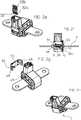
Fig. 1a is an exploded perspective view of an electrical current transducer according to an embodiment of the invention;Fig. 1b is a cross-sectional view of an electrical current transducer according to an embodiment of the invention;Figs. 2a to 2h are perspective views illustrating assembly of an electrical current transducer according to an embodiment of the invention.- Referring to the figures, an exemplary embodiment of an
electric current transducer 2 includes amagnetic core 6 comprising amagnetic circuit gap 22, amagnetic field sensor 8 inserted at least partially in themagnetic circuit gap 22, adielectric housing 10 and aprimary conductor bar 4 extending through acentral passage 18 of the magnetic core. Theprimary conductor bar 4 is integrated in the transducer and comprisesterminals - The
terminals - In an embodiment, the
magnetic field sensor 8 may advantageously comprise acircuit board 24 and a magnetic field detector 9 that may for example be provided in the form of an ASIC (Application Specific Integrated Circuit) 26 mounted on the circuit board. In an embodiment, the magnetic field detector 9 may comprise a Hall effect sensor,per se well known in the art, or may be based on other magnetic field sensing technologies such as magneto-resistive or fluxgate sensors that are also well known in the art. Hall cell magnetic field detectors are widely used in open-loop current sensing applications because of their low cost and good measurement performance in open-loop applications. - The
circuit board 24 comprises circuit traces and various circuit components that may perform some processing of the measurement signal and power supply between the magnetic field detector andelectrical terminals 32 connected to the external circuitry (not shown) for power supply and measurement signal transmission. Each terminal comprises a circuitboard connection end 32a, for instance in a form of a press-fit pin terminal inserted through a plated through-hole in thecircuit board 24, or in the form of other circuit board connection means that areper se well known the art. Theterminals 32 further comprise external connection ends 32b, for instance in a form of pin or tab terminals, positioned within and surrounded by aconnector shroud 30 configured for pluggable coupling to a complementary external connector that's supplies power and transmits the measurement signal to external circuitry (shown). - The
connector shroud 30 may comprise various fixing means such as a latching protrusion or orifice 35for locking the complementary connector thereto. The current measurement signal is thus transmitted from the transducer, and power supplied to the transducer, by means of an external pluggable connector. - Magnetic flux generated by the primary conductor circulates in the
magnetic core 6 and is picked up by the magnetic field detector 9 positioned in themagnetic circuit gap 22. Themagnetic core 6 is preferably made of a single piece ferrite material,per se well known in the art but may also be made of other materials such as stacked laminated sheets of magnetic material that are alsoper se well known in the art. - The
primary conductor bar 4 comprises acore passage section 16 extending between theconnection terminals core passage section 16 has a widthW1 that is smaller than the widthW2 of theprimary conductor bar 4 outside of thecentral passage 18 of thecore 6. The width of the material of theprimary conductor bar 4 at theconnection ends core passage section 16. Thecore passage section 16 thus provides at least oneindent 17 allowing themagnetic core 6 to surround thecore passage section 16 with thegap 22 of the magnetic core being positioned within theindent 17 of theprimary conductor bar 4. This allows the primary conductor bar to have a relatively large cross section respectively connection surface area for adequate connection to the primary conductor in view of the current to be carried, while allowing the transducer to have a compact size and improved performance. - The
housing 10 comprises acore receiving section 28 and aconnector shroud 30. Thecore receiving section 28 houses themagnetic core 6 andmagnetic field sensor 8. Theconnector shroud 30 is configured for connection to an external connector, in particular for pluggable connection to the external connector. Thecore receiving section 28 comprises amain housing portion 20 that is overmolded directly on theprimary conductor bar 4. In an advantageous embodiment, the main housing portion and connector shroud may be integrally formed in an injection overmolding process directly on the primary conductor bar. - The
main housing portion 20 comprises a central overmoldportion 40 that is in direct contact with the primary conductor bar and overlays and completely surrounds thecore passage section 16 of the primary conductor bar. The central overmoldportion 40 comprisesextensions 41 that extend in a direction aligned with the sides of theindent 17 and configured to provideguide rails 46 that are designed to guide and position themagnetic field sensor 8 such that the magnetic field detector 9 is positioned within theindent 17 and in themagnetic circuit gap 22 of the magnetic core. The guide rails 46 may be in a form of slots that engage lateral edges of thecircuit board 24, allowing the circuit board to be inserted into the slot until the magnetic field detector is positioned within the indent. The overmolded main housing portion provides a secure and robust positioning of the magnetic core and magnetic field sensor within the housing in a compact and cost effective manner. - The
central overmold portion 40 advantageously comprisesribs 42 extending in a direction of insertion of themagnetic core 6 in themain housing portion 20, theribs 42 guiding and tightly centering the magnetic core around theprimary conductor bar 4. Theribs 42 engage in a tight fit the inner surface of the magnetic core surrounding thecentral passage 18. - The
central overmold portion 40 comprises athin wall region 43 with reduced wall thickness to allow the mounting of the magnetic core whose airgap faces need to slide along this region. In order to obtain an advantageously small airgap, the thickness of the overmold is reduced here to a nominal value in a range between 0.3 mm and 1.2 mm, preferably in a range between 0.3 and 0.8 mm, depending on the materials used. - After assembly of the
magnetic core 6 in a direction orthogonal to insertion of the magnetic field sensor, through a side of themain housing portion 20, acover portion 34 comprising anorifice 35 may be inserted over theconnection end 12b of the primary conductor bar until the cover portion engages the open side of the main housing portion. The cover portion and main housing portion may be locked together by clipping means, by bonding, or by welding, for instance ultrasonic welding. Depending on the application and the variant, a dielectric potting material may be filled within theouter casing 38 of the main housing before the cover portion is closed against the main housing portion. - After assembly of the
magnetic field sensor 8 in the magnetic fieldsensor receiving slot 44,connector terminals 32 may be inserted into theconnector shroud 30 until connection with thecircuit board 24, for instance by means of a press-fitpin terminal portions 32a inserted in plated through-holes of the circuit board. - The
housing 10 may further comprise acap portion 36 configured to close the open entry and of theslot 44. In the illustrated exemplary embodiment, thecap portion 36 compriseselastic clip arms 48 that engagedcomplementary latching elements 49 on opposite sides of the housing main portion and cover portion. The cap portion may be provided withpins 50 that engage incomplementary holes 51 in the housing to orient and/or lock the cap portion to the main housing portion. The cap portion may alternatively or in addition to the latching means 48, 49 be bonded, or welded to the other housing portions. - electric
current transducer 2primary conductor bar 4- connection ends 12a, 12b
core passage section 16indent 17
magnetic core 6central passage 18magnetic circuit gap 22
magnetic field detector 8circuit board 24ASIC 26
housing 10core receiving section 28main housing portion 20outer casing portion 38central overmold portion 40core guide ribs 42- extensions 41 (for the guide rails 46)
thin wall region 43
- magnetic field
sensor receiving slot 44- guide rails 46
- fixing
orifices 51
- cover
portion 34orifice 35
cap portion 36- clip
arms 48 - pins 50
- clip
- latching elements (protrusions) 49
connector shroud 30
- connector 14
terminals 32- circuit board connection ends 32a
- pin/
tab terminals 32b
- pin/
- circuit board connection ends 32a
Claims (15)
- Electrical current transducer including a primary conductor bar (4) for carrying the current to be measured, a magnetic core (6) comprising a magnetic circuit gap (22), a magnetic field sensor (8) comprising a circuit board (24) and a magnetic field detector positioned in the magnetic circuit gap, and an insulating housing (10) surrounding the magnetic core and magnetic field sensor, the primary conductor bar comprising connection terminal ends (12a, 12b) extending outside of the housing configured for connection to an external primary conductor, the primary conductor bar further comprising a core passage section (16) having a reduced width (W1) in comparison to the connection terminal ends (12a, 12b) extending outside of the housing thereby providing an indent (17) within which the magnetic field detector is positioned such that a central passage (18) of the magnetic core has a width (W3) less than the width (W2) of the primary conductor connection ends (12a, 12b),characterized in that the insulating housing comprises a main housing portion (20) overmolded around the core passage section (16) of the primary conductor bar, the main housing portion comprising a magnetic field sensor receiving slot (44) configured to allow slidable insertion of the magnetic field sensor into the primary conductor bar indent for positioning in the magnetic circuit gap.
- Current transducer according to claim 1, wherein the main housing portion comprises a central overmold portion (40) comprising positioning ribs configured to guide and position the magnetic core around the primary conductor bar.
- Current transducer according to claim 2, wherein the central overmold portion (40) comprises extensions (41) connecting the central overmold portion to an entry end of the magnetic field sensor receiving slot (44) and providing rails (46) to slidably guide and position the magnetic field sensor into the indent (17).
- Current transducer according to claim 2 or 3, wherein the central overmold portion (40) comprises a thin wall region (43) configured for sliding through the magnetic circuit gap during assembly, the thin wall region having a wall thickness in a range between 0.3 mm and 1.2 mm.
- Current transducer according to claim 4, wherein the thin wall region has a wall thickness in a range between 0.3 and 0.8 mm.
- Current transducer according to any of the preceding claims, wherein the main housing portion includes an outer casing (38) and is integrally formed with a connector shroud (30) as a single piece injection overmolded part.
- Current transducer according to any of the preceding claims, wherein the magnetic core is insertable in the main housing portion through a side of the housing in an insertion direction orthogonal to the slidable insertion direction of the magnetic field sensor in the indent.
- Current transducer according to any of the preceding claims, wherein the housing comprises a cover portion (34) mounted against the side of the main housing portion to close the magnetic core therein, the cover portion comprising an orifice (35) for the primary conductor bar and being mountable against the side of the housing in an insertion direction orthogonal to the slidable insertion direction of the magnetic field sensor in the indent.
- Current transducer according to any of the preceding claims, wherein the housing further comprises a cap portion (36) for closing the magnetic field sensor in the magnetic field sensor receiving slot.
- Current transducer according to any of the preceding claims, further comprising a connector (14) configured for pluggable connection to an external connector, the connector comprising a connector shroud (30) and terminals (32) directly mounted and connected to a circuit board (24) of the magnetic field sensor.
- Current transducer according to the preceding claim, wherein the magnetic field detector (9) is in a form of an ASIC and comprises a Hall effect cell.
- Current transducer according to any of the preceding claims, wherein the current transducer is an open-loop current transducer.
- Current transducer according to any of the preceding claims, wherein at least one of the connection ends (12b) of the primary conductor bar (4) is in a form of a connection terminal for a clamping or bolt connection to a primary conductor.
- Current transducer according to any of the preceding claims, wherein the magnetic core is formed of a single piece integrally formed ferrite part.
- Current transducer according to any of the preceding claims 1-13, wherein the magnetic core is formed of a wound tape core with a machined gap.
Priority Applications (5)
| Application Number | Priority Date | Filing Date | Title |
|---|---|---|---|
| EP15164547.0AEP3086130B1 (en) | 2015-04-21 | 2015-04-21 | Current transducer with integrated primary conductor bar |
| KR1020160044346AKR102475347B1 (en) | 2015-04-21 | 2016-04-11 | Current Transducer with Integrated Primary Conductor Bar |
| US15/134,163US9726695B2 (en) | 2015-04-21 | 2016-04-20 | Current transducer with integrated primary conductor bar |
| CN201610245550.9ACN106066418B (en) | 2015-04-21 | 2016-04-20 | Current sensor with integrated primary conductor stick |
| JP2016084285AJP6526597B2 (en) | 2015-04-21 | 2016-04-20 | Current converter with integrated primary conductor bar |
Applications Claiming Priority (1)
| Application Number | Priority Date | Filing Date | Title |
|---|---|---|---|
| EP15164547.0AEP3086130B1 (en) | 2015-04-21 | 2015-04-21 | Current transducer with integrated primary conductor bar |
Publications (2)
| Publication Number | Publication Date |
|---|---|
| EP3086130A1 EP3086130A1 (en) | 2016-10-26 |
| EP3086130B1true EP3086130B1 (en) | 2019-02-06 |
Family
ID=52991633
Family Applications (1)
| Application Number | Title | Priority Date | Filing Date |
|---|---|---|---|
| EP15164547.0AActiveEP3086130B1 (en) | 2015-04-21 | 2015-04-21 | Current transducer with integrated primary conductor bar |
Country Status (5)
| Country | Link |
|---|---|
| US (1) | US9726695B2 (en) |
| EP (1) | EP3086130B1 (en) |
| JP (1) | JP6526597B2 (en) |
| KR (1) | KR102475347B1 (en) |
| CN (1) | CN106066418B (en) |
Cited By (1)
| Publication number | Priority date | Publication date | Assignee | Title |
|---|---|---|---|---|
| IT202300012660A1 (en)* | 2023-06-20 | 2024-12-20 | Tesmec Automation S R L | SATURABLE CURRENT TRANSDUCER |
Families Citing this family (19)
| Publication number | Priority date | Publication date | Assignee | Title |
|---|---|---|---|---|
| EP2924451B1 (en)* | 2014-03-24 | 2019-01-09 | LEM Intellectual Property SA | Current transducer |
| USD803154S1 (en)* | 2015-04-21 | 2017-11-21 | Lem Intellectual Property Sa | Current transducer |
| EP3093672B1 (en)* | 2015-05-09 | 2020-08-12 | LEM International SA | Current transducer with integrated primary conductor bar |
| DE102016216007A1 (en)* | 2016-08-25 | 2018-03-01 | Siemens Aktiengesellschaft | Holder for at least one busbar, component assembly for power electronics with such a holder and method for producing such a holder |
| JP6551362B2 (en) | 2016-10-20 | 2019-07-31 | 株式会社デンソー | Power supply system |
| USD850375S1 (en)* | 2017-01-06 | 2019-06-04 | Lem Intellectual Property Sa | Current transducer |
| US10409283B2 (en) | 2017-03-31 | 2019-09-10 | Mitsubishi Electric Research Laboratories, Inc. | Vehicle motion control system and method |
| JP6732699B2 (en)* | 2017-07-18 | 2020-07-29 | 矢崎総業株式会社 | Current detector |
| DE102017222016A1 (en)* | 2017-12-06 | 2019-06-06 | Zf Friedrichshafen Ag | Connecting device for connecting a busbar of a semiconductor module with a further busbar, power electronics device with a connecting device and method for producing a power electronic device |
| JP6942673B2 (en)* | 2018-07-06 | 2021-09-29 | 東芝三菱電機産業システム株式会社 | Transformer |
| CN109799380B (en)* | 2019-01-29 | 2021-03-02 | 湖南银河电气有限公司 | Integrated current sensor and packaging method thereof |
| EP3715871A1 (en)* | 2019-03-28 | 2020-09-30 | LEM International SA | Current transducer with magnetic core on primary conductor |
| JP7194083B2 (en)* | 2019-07-01 | 2022-12-21 | 株式会社タムラ製作所 | Electronics and current detectors |
| EP3764107B1 (en)* | 2019-07-12 | 2022-03-09 | LEM International SA | Current transducer for measuring residual currents |
| DE102019121385A1 (en)* | 2019-08-07 | 2021-02-11 | Infineon Technologies Ag | DEVICE AND METHOD FOR MOUNTING A MAGNETIC FIELD SENSOR CHIP ON A TRACK |
| US20240369600A1 (en)* | 2021-08-20 | 2024-11-07 | Suzhou Littelfuse Ovs Co., Ltd. | Battery system and hybrid current sensor therefor |
| CN118068065A (en)* | 2022-11-22 | 2024-05-24 | 苏州力特奥维斯保险丝有限公司 | Dual channel current sensor |
| WO2025013210A1 (en)* | 2023-07-11 | 2025-01-16 | 日立Astemo株式会社 | Core member for current detector, current detector, power conversion device, and method for manufacturing core member for current detector |
| FR3159440A1 (en) | 2024-02-16 | 2025-08-22 | Nidec Psa Emotors | Device comprising a housing for a C-shaped magnetic core and a cover |
Family Cites Families (29)
| Publication number | Priority date | Publication date | Assignee | Title |
|---|---|---|---|---|
| JPH0690227B2 (en)* | 1986-09-04 | 1994-11-14 | 本田技研工業株式会社 | In-vehicle electric current detector |
| JPH10267965A (en)* | 1997-03-24 | 1998-10-09 | Nana Electron Kk | Current sensor |
| WO1999010750A1 (en)* | 1997-08-28 | 1999-03-04 | General Electric Company | Self powered current sensor |
| US6686730B2 (en)* | 2002-06-11 | 2004-02-03 | Rockwell Automation Technologies, Inc. | Snap fit Hall effect circuit mount apparatus and method |
| US6781359B2 (en)* | 2002-09-20 | 2004-08-24 | Allegro Microsystems, Inc. | Integrated current sensor |
| JP3896590B2 (en)* | 2002-10-28 | 2007-03-22 | サンケン電気株式会社 | Current detector |
| US7205757B2 (en)* | 2004-09-02 | 2007-04-17 | Denso Corporation | High precision current sensor |
| JP4544087B2 (en) | 2005-08-01 | 2010-09-15 | 株式会社デンソー | Current sensor mounting structure |
| US20070279053A1 (en)* | 2006-05-12 | 2007-12-06 | Taylor William P | Integrated current sensor |
| JP4732968B2 (en) | 2006-06-21 | 2011-07-27 | 矢崎総業株式会社 | Fusible link unit |
| ATE494558T1 (en)* | 2008-01-25 | 2011-01-15 | Lem Liaisons Electron Mec | CURRENT SENSOR |
| KR101090051B1 (en)* | 2009-04-21 | 2011-12-07 | 우리산업 주식회사 | Structure of current sensor and its manufacturing method |
| JP5532843B2 (en)* | 2009-11-17 | 2014-06-25 | 株式会社オートネットワーク技術研究所 | Current detector |
| KR200455870Y1 (en)* | 2009-11-23 | 2011-09-30 | 대성전기공업 주식회사 | Current sensor |
| JP5888840B2 (en) | 2010-08-06 | 2016-03-22 | 矢崎総業株式会社 | Current sensor structure |
| JP5533441B2 (en)* | 2010-08-26 | 2014-06-25 | 株式会社オートネットワーク技術研究所 | Current detection device and manufacturing method thereof |
| JP2012058199A (en)* | 2010-09-13 | 2012-03-22 | Sumitomo Wiring Syst Ltd | Current detection apparatus |
| KR101225514B1 (en)* | 2011-03-09 | 2013-01-23 | 우리산업 주식회사 | Current sensor assembly |
| KR101169910B1 (en) | 2011-03-09 | 2012-08-06 | 우리산업 주식회사 | Current sensor assembly |
| JP2012242203A (en)* | 2011-05-18 | 2012-12-10 | Auto Network Gijutsu Kenkyusho:Kk | Current detection device |
| US8604777B2 (en)* | 2011-07-13 | 2013-12-10 | Allegro Microsystems, Llc | Current sensor with calibration for a current divider configuration |
| KR20130011385A (en)* | 2011-07-21 | 2013-01-30 | 한국단자공업 주식회사 | Shock detecting apparatus and assembling method |
| JP2013148512A (en)* | 2012-01-20 | 2013-08-01 | Aisin Seiki Co Ltd | Current sensor |
| JP2013205194A (en) | 2012-03-28 | 2013-10-07 | Sumitomo Electric Ind Ltd | Current sensor |
| JP2013217866A (en)* | 2012-04-12 | 2013-10-24 | Sumitomo Wiring Syst Ltd | Electrical junction box and current sensor |
| EP2741090B1 (en)* | 2012-12-07 | 2015-07-29 | LEM Intellectual Property SA | Electrical current transducer with wound magnetic core |
| JP2015049061A (en) | 2013-08-30 | 2015-03-16 | 旭化成エレクトロニクス株式会社 | Current sensor |
| EP2921865A1 (en)* | 2014-03-21 | 2015-09-23 | LEM Intellectual Property SA | Magnetic field sensor arrangement and current transducer therewith |
| EP3093672B1 (en)* | 2015-05-09 | 2020-08-12 | LEM International SA | Current transducer with integrated primary conductor bar |
- 2015
- 2015-04-21EPEP15164547.0Apatent/EP3086130B1/enactiveActive
- 2016
- 2016-04-11KRKR1020160044346Apatent/KR102475347B1/enactiveActive
- 2016-04-20JPJP2016084285Apatent/JP6526597B2/enactiveActive
- 2016-04-20USUS15/134,163patent/US9726695B2/ennot_activeExpired - Fee Related
- 2016-04-20CNCN201610245550.9Apatent/CN106066418B/enactiveActive
Non-Patent Citations (1)
| Title |
|---|
| None* |
Cited By (1)
| Publication number | Priority date | Publication date | Assignee | Title |
|---|---|---|---|---|
| IT202300012660A1 (en)* | 2023-06-20 | 2024-12-20 | Tesmec Automation S R L | SATURABLE CURRENT TRANSDUCER |
Also Published As
| Publication number | Publication date |
|---|---|
| KR102475347B1 (en) | 2022-12-07 |
| JP6526597B2 (en) | 2019-06-05 |
| CN106066418A (en) | 2016-11-02 |
| CN106066418B (en) | 2019-11-22 |
| EP3086130A1 (en) | 2016-10-26 |
| KR20160125291A (en) | 2016-10-31 |
| JP2016206195A (en) | 2016-12-08 |
| US9726695B2 (en) | 2017-08-08 |
| US20160313373A1 (en) | 2016-10-27 |
Similar Documents
| Publication | Publication Date | Title |
|---|---|---|
| EP3086130B1 (en) | Current transducer with integrated primary conductor bar | |
| JP6830986B2 (en) | Current converter | |
| JP7289869B2 (en) | Current converter with integrated primary conductor bar | |
| EP2771701B1 (en) | Electrical current transducer | |
| US10295574B2 (en) | Clip-on current transducer or current transformer | |
| US10989740B2 (en) | Closed-loop current transducer | |
| US11994538B2 (en) | Current transducer with magnetic core on primary conductor bar |
Legal Events
| Date | Code | Title | Description |
|---|---|---|---|
| PUAI | Public reference made under article 153(3) epc to a published international application that has entered the european phase | Free format text:ORIGINAL CODE: 0009012 | |
| AK | Designated contracting states | Kind code of ref document:A1 Designated state(s):AL AT BE BG CH CY CZ DE DK EE ES FI FR GB GR HR HU IE IS IT LI LT LU LV MC MK MT NL NO PL PT RO RS SE SI SK SM TR | |
| AX | Request for extension of the european patent | Extension state:BA ME | |
| STAA | Information on the status of an ep patent application or granted ep patent | Free format text:STATUS: REQUEST FOR EXAMINATION WAS MADE | |
| 17P | Request for examination filed | Effective date:20161128 | |
| RBV | Designated contracting states (corrected) | Designated state(s):AL AT BE BG CH CY CZ DE DK EE ES FI FR GB GR HR HU IE IS IT LI LT LU LV MC MK MT NL NO PL PT RO RS SE SI SK SM TR | |
| GRAP | Despatch of communication of intention to grant a patent | Free format text:ORIGINAL CODE: EPIDOSNIGR1 | |
| STAA | Information on the status of an ep patent application or granted ep patent | Free format text:STATUS: GRANT OF PATENT IS INTENDED | |
| INTG | Intention to grant announced | Effective date:20180926 | |
| GRAS | Grant fee paid | Free format text:ORIGINAL CODE: EPIDOSNIGR3 | |
| GRAA | (expected) grant | Free format text:ORIGINAL CODE: 0009210 | |
| STAA | Information on the status of an ep patent application or granted ep patent | Free format text:STATUS: THE PATENT HAS BEEN GRANTED | |
| AK | Designated contracting states | Kind code of ref document:B1 Designated state(s):AL AT BE BG CH CY CZ DE DK EE ES FI FR GB GR HR HU IE IS IT LI LT LU LV MC MK MT NL NO PL PT RO RS SE SI SK SM TR | |
| REG | Reference to a national code | Ref country code:GB Ref legal event code:FG4D | |
| REG | Reference to a national code | Ref country code:CH Ref legal event code:EP Ref country code:CH Ref legal event code:NV Representative=s name:REUTELER AND CIE S.A., CH Ref country code:AT Ref legal event code:REF Ref document number:1095244 Country of ref document:AT Kind code of ref document:T Effective date:20190215 | |
| REG | Reference to a national code | Ref country code:IE Ref legal event code:FG4D | |
| REG | Reference to a national code | Ref country code:DE Ref legal event code:R096 Ref document number:602015024263 Country of ref document:DE | |
| REG | Reference to a national code | Ref country code:NL Ref legal event code:MP Effective date:20190206 | |
| REG | Reference to a national code | Ref country code:LT Ref legal event code:MG4D | |
| PG25 | Lapsed in a contracting state [announced via postgrant information from national office to epo] | Ref country code:FI Free format text:LAPSE BECAUSE OF FAILURE TO SUBMIT A TRANSLATION OF THE DESCRIPTION OR TO PAY THE FEE WITHIN THE PRESCRIBED TIME-LIMIT Effective date:20190206 Ref country code:NO Free format text:LAPSE BECAUSE OF FAILURE TO SUBMIT A TRANSLATION OF THE DESCRIPTION OR TO PAY THE FEE WITHIN THE PRESCRIBED TIME-LIMIT Effective date:20190506 Ref country code:PT Free format text:LAPSE BECAUSE OF FAILURE TO SUBMIT A TRANSLATION OF THE DESCRIPTION OR TO PAY THE FEE WITHIN THE PRESCRIBED TIME-LIMIT Effective date:20190606 Ref country code:SE Free format text:LAPSE BECAUSE OF FAILURE TO SUBMIT A TRANSLATION OF THE DESCRIPTION OR TO PAY THE FEE WITHIN THE PRESCRIBED TIME-LIMIT Effective date:20190206 Ref country code:NL Free format text:LAPSE BECAUSE OF FAILURE TO SUBMIT A TRANSLATION OF THE DESCRIPTION OR TO PAY THE FEE WITHIN THE PRESCRIBED TIME-LIMIT Effective date:20190206 Ref country code:LT Free format text:LAPSE BECAUSE OF FAILURE TO SUBMIT A TRANSLATION OF THE DESCRIPTION OR TO PAY THE FEE WITHIN THE PRESCRIBED TIME-LIMIT Effective date:20190206 | |
| REG | Reference to a national code | Ref country code:AT Ref legal event code:MK05 Ref document number:1095244 Country of ref document:AT Kind code of ref document:T Effective date:20190206 | |
| PG25 | Lapsed in a contracting state [announced via postgrant information from national office to epo] | Ref country code:LV Free format text:LAPSE BECAUSE OF FAILURE TO SUBMIT A TRANSLATION OF THE DESCRIPTION OR TO PAY THE FEE WITHIN THE PRESCRIBED TIME-LIMIT Effective date:20190206 Ref country code:GR Free format text:LAPSE BECAUSE OF FAILURE TO SUBMIT A TRANSLATION OF THE DESCRIPTION OR TO PAY THE FEE WITHIN THE PRESCRIBED TIME-LIMIT Effective date:20190507 Ref country code:HR Free format text:LAPSE BECAUSE OF FAILURE TO SUBMIT A TRANSLATION OF THE DESCRIPTION OR TO PAY THE FEE WITHIN THE PRESCRIBED TIME-LIMIT Effective date:20190206 Ref country code:BG Free format text:LAPSE BECAUSE OF FAILURE TO SUBMIT A TRANSLATION OF THE DESCRIPTION OR TO PAY THE FEE WITHIN THE PRESCRIBED TIME-LIMIT Effective date:20190506 Ref country code:IS Free format text:LAPSE BECAUSE OF FAILURE TO SUBMIT A TRANSLATION OF THE DESCRIPTION OR TO PAY THE FEE WITHIN THE PRESCRIBED TIME-LIMIT Effective date:20190606 Ref country code:RS Free format text:LAPSE BECAUSE OF FAILURE TO SUBMIT A TRANSLATION OF THE DESCRIPTION OR TO PAY THE FEE WITHIN THE PRESCRIBED TIME-LIMIT Effective date:20190206 | |
| PG25 | Lapsed in a contracting state [announced via postgrant information from national office to epo] | Ref country code:DK Free format text:LAPSE BECAUSE OF FAILURE TO SUBMIT A TRANSLATION OF THE DESCRIPTION OR TO PAY THE FEE WITHIN THE PRESCRIBED TIME-LIMIT Effective date:20190206 Ref country code:EE Free format text:LAPSE BECAUSE OF FAILURE TO SUBMIT A TRANSLATION OF THE DESCRIPTION OR TO PAY THE FEE WITHIN THE PRESCRIBED TIME-LIMIT Effective date:20190206 Ref country code:ES Free format text:LAPSE BECAUSE OF FAILURE TO SUBMIT A TRANSLATION OF THE DESCRIPTION OR TO PAY THE FEE WITHIN THE PRESCRIBED TIME-LIMIT Effective date:20190206 Ref country code:RO Free format text:LAPSE BECAUSE OF FAILURE TO SUBMIT A TRANSLATION OF THE DESCRIPTION OR TO PAY THE FEE WITHIN THE PRESCRIBED TIME-LIMIT Effective date:20190206 Ref country code:CZ Free format text:LAPSE BECAUSE OF FAILURE TO SUBMIT A TRANSLATION OF THE DESCRIPTION OR TO PAY THE FEE WITHIN THE PRESCRIBED TIME-LIMIT Effective date:20190206 Ref country code:IT Free format text:LAPSE BECAUSE OF FAILURE TO SUBMIT A TRANSLATION OF THE DESCRIPTION OR TO PAY THE FEE WITHIN THE PRESCRIBED TIME-LIMIT Effective date:20190206 Ref country code:AL Free format text:LAPSE BECAUSE OF FAILURE TO SUBMIT A TRANSLATION OF THE DESCRIPTION OR TO PAY THE FEE WITHIN THE PRESCRIBED TIME-LIMIT Effective date:20190206 Ref country code:SK Free format text:LAPSE BECAUSE OF FAILURE TO SUBMIT A TRANSLATION OF THE DESCRIPTION OR TO PAY THE FEE WITHIN THE PRESCRIBED TIME-LIMIT Effective date:20190206 | |
| REG | Reference to a national code | Ref country code:DE Ref legal event code:R097 Ref document number:602015024263 Country of ref document:DE | |
| PG25 | Lapsed in a contracting state [announced via postgrant information from national office to epo] | Ref country code:PL Free format text:LAPSE BECAUSE OF FAILURE TO SUBMIT A TRANSLATION OF THE DESCRIPTION OR TO PAY THE FEE WITHIN THE PRESCRIBED TIME-LIMIT Effective date:20190206 Ref country code:SM Free format text:LAPSE BECAUSE OF FAILURE TO SUBMIT A TRANSLATION OF THE DESCRIPTION OR TO PAY THE FEE WITHIN THE PRESCRIBED TIME-LIMIT Effective date:20190206 | |
| PLBE | No opposition filed within time limit | Free format text:ORIGINAL CODE: 0009261 | |
| STAA | Information on the status of an ep patent application or granted ep patent | Free format text:STATUS: NO OPPOSITION FILED WITHIN TIME LIMIT | |
| REG | Reference to a national code | Ref country code:BE Ref legal event code:MM Effective date:20190430 | |
| REG | Reference to a national code | Ref country code:CH Ref legal event code:PUE Owner name:LEM INTERNATIONAL SA, CH Free format text:FORMER OWNER: LEM INTELLECTUAL PROPERTY SA, CH | |
| PG25 | Lapsed in a contracting state [announced via postgrant information from national office to epo] | Ref country code:MC Free format text:LAPSE BECAUSE OF FAILURE TO SUBMIT A TRANSLATION OF THE DESCRIPTION OR TO PAY THE FEE WITHIN THE PRESCRIBED TIME-LIMIT Effective date:20190206 Ref country code:LU Free format text:LAPSE BECAUSE OF NON-PAYMENT OF DUE FEES Effective date:20190421 Ref country code:AT Free format text:LAPSE BECAUSE OF FAILURE TO SUBMIT A TRANSLATION OF THE DESCRIPTION OR TO PAY THE FEE WITHIN THE PRESCRIBED TIME-LIMIT Effective date:20190206 | |
| 26N | No opposition filed | Effective date:20191107 | |
| GBPC | Gb: european patent ceased through non-payment of renewal fee | Effective date:20190506 | |
| PG25 | Lapsed in a contracting state [announced via postgrant information from national office to epo] | Ref country code:BE Free format text:LAPSE BECAUSE OF NON-PAYMENT OF DUE FEES Effective date:20190430 Ref country code:SI Free format text:LAPSE BECAUSE OF FAILURE TO SUBMIT A TRANSLATION OF THE DESCRIPTION OR TO PAY THE FEE WITHIN THE PRESCRIBED TIME-LIMIT Effective date:20190206 | |
| PG25 | Lapsed in a contracting state [announced via postgrant information from national office to epo] | Ref country code:TR Free format text:LAPSE BECAUSE OF FAILURE TO SUBMIT A TRANSLATION OF THE DESCRIPTION OR TO PAY THE FEE WITHIN THE PRESCRIBED TIME-LIMIT Effective date:20190206 | |
| REG | Reference to a national code | Ref country code:DE Ref legal event code:R081 Ref document number:602015024263 Country of ref document:DE Owner name:LEM INTERNATIONAL SA, CH Free format text:FORMER OWNER: LEM INTELLECTUAL PROPERTY SA, FRIBOURG, CH | |
| PG25 | Lapsed in a contracting state [announced via postgrant information from national office to epo] | Ref country code:GB Free format text:LAPSE BECAUSE OF NON-PAYMENT OF DUE FEES Effective date:20190506 Ref country code:IE Free format text:LAPSE BECAUSE OF NON-PAYMENT OF DUE FEES Effective date:20190421 | |
| PG25 | Lapsed in a contracting state [announced via postgrant information from national office to epo] | Ref country code:CY Free format text:LAPSE BECAUSE OF FAILURE TO SUBMIT A TRANSLATION OF THE DESCRIPTION OR TO PAY THE FEE WITHIN THE PRESCRIBED TIME-LIMIT Effective date:20190206 | |
| PG25 | Lapsed in a contracting state [announced via postgrant information from national office to epo] | Ref country code:MT Free format text:LAPSE BECAUSE OF FAILURE TO SUBMIT A TRANSLATION OF THE DESCRIPTION OR TO PAY THE FEE WITHIN THE PRESCRIBED TIME-LIMIT Effective date:20190206 Ref country code:HU Free format text:LAPSE BECAUSE OF FAILURE TO SUBMIT A TRANSLATION OF THE DESCRIPTION OR TO PAY THE FEE WITHIN THE PRESCRIBED TIME-LIMIT; INVALID AB INITIO Effective date:20150421 | |
| PG25 | Lapsed in a contracting state [announced via postgrant information from national office to epo] | Ref country code:MK Free format text:LAPSE BECAUSE OF FAILURE TO SUBMIT A TRANSLATION OF THE DESCRIPTION OR TO PAY THE FEE WITHIN THE PRESCRIBED TIME-LIMIT Effective date:20190206 | |
| PGFP | Annual fee paid to national office [announced via postgrant information from national office to epo] | Ref country code:DE Payment date:20250422 Year of fee payment:11 | |
| PGFP | Annual fee paid to national office [announced via postgrant information from national office to epo] | Ref country code:FR Payment date:20250425 Year of fee payment:11 | |
| PGFP | Annual fee paid to national office [announced via postgrant information from national office to epo] | Ref country code:CH Payment date:20250501 Year of fee payment:11 |