EP3082660B1 - Device delivery system - Google Patents
Device delivery systemDownload PDFInfo
- Publication number
- EP3082660B1 EP3082660B1EP14870946.2AEP14870946AEP3082660B1EP 3082660 B1EP3082660 B1EP 3082660B1EP 14870946 AEP14870946 AEP 14870946AEP 3082660 B1EP3082660 B1EP 3082660B1
- Authority
- EP
- European Patent Office
- Prior art keywords
- coil
- catheter
- embolic coil
- embolic
- distal
- Prior art date
- Legal status (The legal status is an assumption and is not a legal conclusion. Google has not performed a legal analysis and makes no representation as to the accuracy of the status listed.)
- Active
Links
- 230000003073embolic effectEffects0.000claimsdescription143
- 238000004891communicationMethods0.000claimsdescription7
- 230000004044responseEffects0.000claimsdescription5
- 230000000593degrading effectEffects0.000claimsdescription4
- 239000000463materialSubstances0.000description43
- 230000007246mechanismEffects0.000description23
- 229910052751metalInorganic materials0.000description23
- 239000002184metalSubstances0.000description21
- 238000010438heat treatmentMethods0.000description18
- BASFCYQUMIYNBI-UHFFFAOYSA-NplatinumChemical compound[Pt]BASFCYQUMIYNBI-UHFFFAOYSA-N0.000description18
- 239000012530fluidSubstances0.000description15
- 210000005166vasculatureAnatomy0.000description13
- 238000000034methodMethods0.000description12
- 229920000642polymerPolymers0.000description12
- 206010002329AneurysmDiseases0.000description11
- 239000002775capsuleSubstances0.000description9
- 238000009432framingMethods0.000description9
- 239000010410layerSubstances0.000description9
- 229910052697platinumInorganic materials0.000description9
- 239000004642PolyimideSubstances0.000description8
- 239000000853adhesiveSubstances0.000description8
- 230000001070adhesive effectEffects0.000description8
- 239000012528membraneSubstances0.000description8
- 229920001721polyimidePolymers0.000description8
- 229910001566austeniteInorganic materials0.000description6
- 238000005452bendingMethods0.000description6
- 239000000017hydrogelSubstances0.000description6
- 230000036244malformationEffects0.000description6
- HLXZNVUGXRDIFK-UHFFFAOYSA-Nnickel titaniumChemical compound[Ti].[Ti].[Ti].[Ti].[Ti].[Ti].[Ti].[Ti].[Ti].[Ti].[Ti].[Ni].[Ni].[Ni].[Ni].[Ni].[Ni].[Ni].[Ni].[Ni].[Ni].[Ni].[Ni].[Ni].[Ni]HLXZNVUGXRDIFK-UHFFFAOYSA-N0.000description6
- 229910001000nickel titaniumInorganic materials0.000description6
- -1polyethylenePolymers0.000description6
- 230000007704transitionEffects0.000description6
- FAPWRFPIFSIZLT-UHFFFAOYSA-MSodium chlorideChemical compound[Na+].[Cl-]FAPWRFPIFSIZLT-UHFFFAOYSA-M0.000description5
- 239000004020conductorSubstances0.000description5
- PCHJSUWPFVWCPO-UHFFFAOYSA-NgoldChemical compound[Au]PCHJSUWPFVWCPO-UHFFFAOYSA-N0.000description5
- 229910052737goldInorganic materials0.000description5
- 239000010931goldSubstances0.000description5
- 238000002844meltingMethods0.000description5
- 230000008018meltingEffects0.000description5
- 229910001220stainless steelInorganic materials0.000description5
- 239000010935stainless steelSubstances0.000description5
- 239000008280bloodSubstances0.000description4
- 210000004369bloodAnatomy0.000description4
- 238000013461designMethods0.000description4
- 239000003814drugSubstances0.000description4
- 229940079593drugDrugs0.000description4
- 239000011780sodium chlorideSubstances0.000description4
- 239000007787solidSubstances0.000description4
- 229910052721tungstenInorganic materials0.000description4
- 239000010937tungstenSubstances0.000description4
- WFKWXMTUELFFGS-UHFFFAOYSA-NtungstenChemical compound[W]WFKWXMTUELFFGS-UHFFFAOYSA-N0.000description4
- 230000007998vessel formationEffects0.000description4
- 239000004698PolyethyleneSubstances0.000description3
- 230000009471actionEffects0.000description3
- 239000000919ceramicSubstances0.000description3
- 230000007423decreaseEffects0.000description3
- 239000007788liquidSubstances0.000description3
- 150000002739metalsChemical class0.000description3
- 229920000573polyethylenePolymers0.000description3
- 229920001343polytetrafluoroethylenePolymers0.000description3
- 239000004810polytetrafluoroethyleneSubstances0.000description3
- 238000010926purgeMethods0.000description3
- 150000003839saltsChemical class0.000description3
- LFQSCWFLJHTTHZ-UHFFFAOYSA-NEthanolChemical compoundCCOLFQSCWFLJHTTHZ-UHFFFAOYSA-N0.000description2
- KDLHZDBZIXYQEI-UHFFFAOYSA-NPalladiumChemical compound[Pd]KDLHZDBZIXYQEI-UHFFFAOYSA-N0.000description2
- RTAQQCXQSZGOHL-UHFFFAOYSA-NTitaniumChemical compound[Ti]RTAQQCXQSZGOHL-UHFFFAOYSA-N0.000description2
- 239000000560biocompatible materialSubstances0.000description2
- 230000036760body temperatureEffects0.000description2
- 230000015556catabolic processEffects0.000description2
- 238000000576coating methodMethods0.000description2
- 239000002131composite materialSubstances0.000description2
- 238000006731degradation reactionMethods0.000description2
- 230000005611electricityEffects0.000description2
- 239000010408filmSubstances0.000description2
- 229910000734martensiteInorganic materials0.000description2
- 238000005259measurementMethods0.000description2
- 239000000155meltSubstances0.000description2
- 238000007747platingMethods0.000description2
- 229920000139polyethylene terephthalatePolymers0.000description2
- 239000005020polyethylene terephthalateSubstances0.000description2
- 229910052715tantalumInorganic materials0.000description2
- GUVRBAGPIYLISA-UHFFFAOYSA-Ntantalum atomChemical compound[Ta]GUVRBAGPIYLISA-UHFFFAOYSA-N0.000description2
- 239000010936titaniumSubstances0.000description2
- 229910052719titaniumInorganic materials0.000description2
- 238000012546transferMethods0.000description2
- 238000003466weldingMethods0.000description2
- PJRSUKFWFKUDTH-JWDJOUOUSA-N(2s)-6-amino-2-[[2-[[(2s)-2-[[(2s,3s)-2-[[(2s)-2-[[2-[[(2s)-2-[[(2s)-6-amino-2-[[(2s)-2-[[(2s)-2-[[(2s)-2-[(2-aminoacetyl)amino]-4-methylsulfanylbutanoyl]amino]propanoyl]amino]-3-hydroxypropanoyl]amino]hexanoyl]amino]propanoyl]amino]acetyl]amino]propanoylChemical compoundCSCC[C@H](NC(=O)CN)C(=O)N[C@@H](C)C(=O)N[C@@H](CO)C(=O)N[C@@H](CCCCN)C(=O)N[C@@H](C)C(=O)NCC(=O)N[C@@H](C)C(=O)N[C@@H]([C@@H](C)CC)C(=O)N[C@@H](C)C(=O)NCC(=O)N[C@@H](CCCCN)C(=O)N[C@@H]([C@@H](C)CC)C(=O)N[C@@H](C)C(=O)N[C@@H](CCCCN)C(=O)N[C@@H](C(C)C)C(=O)N[C@@H](C)C(=O)N[C@@H](CC(C)C)C(=O)N[C@@H](CCCCN)C(=O)N[C@@H](C)C(=O)N[C@@H](CC(C)C)C(N)=OPJRSUKFWFKUDTH-JWDJOUOUSA-N0.000description1
- 208000022211Arteriovenous MalformationsDiseases0.000description1
- 206010016717FistulaDiseases0.000description1
- 208000008883Patent Foramen OvaleDiseases0.000description1
- 229910000639Spring steelInorganic materials0.000description1
- 239000004809TeflonSubstances0.000description1
- 229920006362Teflon®Polymers0.000description1
- 230000003213activating effectEffects0.000description1
- 230000004913activationEffects0.000description1
- 210000003484anatomyAnatomy0.000description1
- 230000005744arteriovenous malformationEffects0.000description1
- 208000013914atrial heart septal defectDiseases0.000description1
- 230000009286beneficial effectEffects0.000description1
- 230000005540biological transmissionEffects0.000description1
- 239000007767bonding agentSubstances0.000description1
- 239000003990capacitorSubstances0.000description1
- 229910010293ceramic materialInorganic materials0.000description1
- 230000008859changeEffects0.000description1
- 239000011248coating agentSubstances0.000description1
- 230000007797corrosionEffects0.000description1
- 238000005260corrosionMethods0.000description1
- 230000003247decreasing effectEffects0.000description1
- 230000001419dependent effectEffects0.000description1
- 230000000881depressing effectEffects0.000description1
- 238000001514detection methodMethods0.000description1
- 238000012377drug deliveryMethods0.000description1
- 239000002355dual-layerSubstances0.000description1
- 230000000694effectsEffects0.000description1
- 230000010102embolizationEffects0.000description1
- 238000005516engineering processMethods0.000description1
- 230000003890fistulaEffects0.000description1
- 239000006260foamSubstances0.000description1
- 239000003292glueSubstances0.000description1
- 239000007943implantSubstances0.000description1
- 230000000977initiatory effectEffects0.000description1
- 239000011810insulating materialSubstances0.000description1
- 230000002452interceptive effectEffects0.000description1
- PNDPGZBMCMUPRI-UHFFFAOYSA-NiodineChemical compoundIIPNDPGZBMCMUPRI-UHFFFAOYSA-N0.000description1
- 150000002500ionsChemical class0.000description1
- 238000003698laser cuttingMethods0.000description1
- 210000005248left atrial appendageAnatomy0.000description1
- QSHDDOUJBYECFT-UHFFFAOYSA-NmercuryChemical compound[Hg]QSHDDOUJBYECFT-UHFFFAOYSA-N0.000description1
- 229910052753mercuryInorganic materials0.000description1
- 238000012986modificationMethods0.000description1
- 230000004048modificationEffects0.000description1
- 239000012811non-conductive materialSubstances0.000description1
- 230000003287optical effectEffects0.000description1
- 210000003101oviductAnatomy0.000description1
- 229910052763palladiumInorganic materials0.000description1
- 208000003278patent ductus arteriosusDiseases0.000description1
- 108010021753peptide-Gly-Leu-amideProteins0.000description1
- 230000002093peripheral effectEffects0.000description1
- 229920000098polyolefinPolymers0.000description1
- 229920002635polyurethanePolymers0.000description1
- 239000004814polyurethaneSubstances0.000description1
- 230000001954sterilising effectEffects0.000description1
- 238000004659sterilization and disinfectionMethods0.000description1
- 230000008685targetingEffects0.000description1
- 239000010409thin filmSubstances0.000description1
- 230000000007visual effectEffects0.000description1
- 238000009736wettingMethods0.000description1
Images


Classifications
- A—HUMAN NECESSITIES
- A61—MEDICAL OR VETERINARY SCIENCE; HYGIENE
- A61M—DEVICES FOR INTRODUCING MEDIA INTO, OR ONTO, THE BODY; DEVICES FOR TRANSDUCING BODY MEDIA OR FOR TAKING MEDIA FROM THE BODY; DEVICES FOR PRODUCING OR ENDING SLEEP OR STUPOR
- A61M25/00—Catheters; Hollow probes
- A61M25/01—Introducing, guiding, advancing, emplacing or holding catheters
- A61M25/09—Guide wires
- A61M25/09041—Mechanisms for insertion of guide wires
- A—HUMAN NECESSITIES
- A61—MEDICAL OR VETERINARY SCIENCE; HYGIENE
- A61B—DIAGNOSIS; SURGERY; IDENTIFICATION
- A61B17/00—Surgical instruments, devices or methods
- A61B17/12—Surgical instruments, devices or methods for ligaturing or otherwise compressing tubular parts of the body, e.g. blood vessels or umbilical cord
- A61B17/12022—Occluding by internal devices, e.g. balloons or releasable wires
- A61B17/12131—Occluding by internal devices, e.g. balloons or releasable wires characterised by the type of occluding device
- A61B17/1214—Coils or wires
- A—HUMAN NECESSITIES
- A61—MEDICAL OR VETERINARY SCIENCE; HYGIENE
- A61B—DIAGNOSIS; SURGERY; IDENTIFICATION
- A61B17/00—Surgical instruments, devices or methods
- A61B17/12—Surgical instruments, devices or methods for ligaturing or otherwise compressing tubular parts of the body, e.g. blood vessels or umbilical cord
- A61B17/12022—Occluding by internal devices, e.g. balloons or releasable wires
- A61B17/12131—Occluding by internal devices, e.g. balloons or releasable wires characterised by the type of occluding device
- A61B17/12163—Occluding by internal devices, e.g. balloons or releasable wires characterised by the type of occluding device having a string of elements connected to each other
- A—HUMAN NECESSITIES
- A61—MEDICAL OR VETERINARY SCIENCE; HYGIENE
- A61M—DEVICES FOR INTRODUCING MEDIA INTO, OR ONTO, THE BODY; DEVICES FOR TRANSDUCING BODY MEDIA OR FOR TAKING MEDIA FROM THE BODY; DEVICES FOR PRODUCING OR ENDING SLEEP OR STUPOR
- A61M25/00—Catheters; Hollow probes
- A61M25/01—Introducing, guiding, advancing, emplacing or holding catheters
- A61M25/0105—Steering means as part of the catheter or advancing means; Markers for positioning
- A61M25/0133—Tip steering devices
- A61M25/0138—Tip steering devices having flexible regions as a result of weakened outer material, e.g. slots, slits, cuts, joints or coils
- A—HUMAN NECESSITIES
- A61—MEDICAL OR VETERINARY SCIENCE; HYGIENE
- A61M—DEVICES FOR INTRODUCING MEDIA INTO, OR ONTO, THE BODY; DEVICES FOR TRANSDUCING BODY MEDIA OR FOR TAKING MEDIA FROM THE BODY; DEVICES FOR PRODUCING OR ENDING SLEEP OR STUPOR
- A61M25/00—Catheters; Hollow probes
- A61M25/01—Introducing, guiding, advancing, emplacing or holding catheters
- A61M25/0105—Steering means as part of the catheter or advancing means; Markers for positioning
- A61M25/0133—Tip steering devices
- A61M25/0158—Tip steering devices with magnetic or electrical means, e.g. by using piezo materials, electroactive polymers, magnetic materials or by heating of shape memory materials
- A—HUMAN NECESSITIES
- A61—MEDICAL OR VETERINARY SCIENCE; HYGIENE
- A61B—DIAGNOSIS; SURGERY; IDENTIFICATION
- A61B17/00—Surgical instruments, devices or methods
- A61B2017/00017—Electrical control of surgical instruments
- A61B2017/00115—Electrical control of surgical instruments with audible or visual output
- A—HUMAN NECESSITIES
- A61—MEDICAL OR VETERINARY SCIENCE; HYGIENE
- A61B—DIAGNOSIS; SURGERY; IDENTIFICATION
- A61B17/00—Surgical instruments, devices or methods
- A61B17/12—Surgical instruments, devices or methods for ligaturing or otherwise compressing tubular parts of the body, e.g. blood vessels or umbilical cord
- A61B17/12022—Occluding by internal devices, e.g. balloons or releasable wires
- A61B2017/1205—Introduction devices
- A61B2017/12054—Details concerning the detachment of the occluding device from the introduction device
- A61B2017/12063—Details concerning the detachment of the occluding device from the introduction device electrolytically detachable
- A—HUMAN NECESSITIES
- A61—MEDICAL OR VETERINARY SCIENCE; HYGIENE
- A61B—DIAGNOSIS; SURGERY; IDENTIFICATION
- A61B17/00—Surgical instruments, devices or methods
- A61B17/12—Surgical instruments, devices or methods for ligaturing or otherwise compressing tubular parts of the body, e.g. blood vessels or umbilical cord
- A61B17/12022—Occluding by internal devices, e.g. balloons or releasable wires
- A61B2017/1205—Introduction devices
- A61B2017/12054—Details concerning the detachment of the occluding device from the introduction device
- A61B2017/12068—Details concerning the detachment of the occluding device from the introduction device detachable by heat
- A—HUMAN NECESSITIES
- A61—MEDICAL OR VETERINARY SCIENCE; HYGIENE
- A61B—DIAGNOSIS; SURGERY; IDENTIFICATION
- A61B17/00—Surgical instruments, devices or methods
- A61B17/12—Surgical instruments, devices or methods for ligaturing or otherwise compressing tubular parts of the body, e.g. blood vessels or umbilical cord
- A61B17/12022—Occluding by internal devices, e.g. balloons or releasable wires
- A61B2017/1205—Introduction devices
- A61B2017/12054—Details concerning the detachment of the occluding device from the introduction device
- A61B2017/1209—Details concerning the detachment of the occluding device from the introduction device detachable by electrical current or potential, e.g. electroactive polymer
Definitions
- a catheter sensor systemmay be used to interact with an embolic coil in order to detach the embolic coil at one or more points along the coil.
- the catheter sensor systemmay also be used with other devices such as a guidewire.
- the guidewiremay bend in response to an impulse conveyed via electrical contact with the one or more catheter sensors.
- Document US2013296917discloses an embolic coil delivery system comprising a catheter including a first contact and a second contact, an embolic coil including two coil segments separated by a link, wherein the link includes a proximal conductive sleeve, a distal conductive sleeve, and a monofilament between the proximal and the distal conductive sleeves, the monofilament being degradable.
- an embolic coilin another embodiment includes coil segments comprising the same type of coil.
- a guidewire steering systemcomprises a bimetallic guidewire and a catheter with electrical contacts.
- a combined embolic coil detachment and guidewire steering systemcomprises a catheter with electric contacts used to interface with an embolic coil and/or guidewire.
- an embolic coilis in electric communication with one terminal of a power supply and a contact on a catheter is in electric communication with another terminal of a power supply.
- a catheterin another embodiment, includes a heating coil formed by laser cutting a metal hypotube or a thin, flat, metal sheet.
- Several heating coilscan be arranged in overlapping layers within each other, axially in series along the catheter's length, or in parallel, adjacent to each other.
- FIG. 1An embolic coil detachment system according to the invention is shown in figures 1-20 and includes an embolic coil and a detachment system.
- Figure 1illustrates a coil 10 used in an embolic coil detachment system.
- the coil 10includes a plurality of coil segments 12 separated by links 14 between the segments.
- the links 14are degradable and, when the links are degraded sufficiently, the coil segment 12 detaches from the rest of coil 10.
- FIG 2illustrates a detachment system that can be used with the embolic coil 10 of Figure 1 .
- the detachment systemincludes a heater 16 which is located at a distal end of wire track member 18, which is preferably sized to locate the heater 16 near a distal end of a catheter. As previously discussed, the heater 16 can melt or degrade the links 14 to cause detachment between two of the various coil segments 12 from coil 10.
- Figure 2ashows a closer view of the heater 16 and wire track member 18.
- One of the current lines 19connects to the proximal part of the heater 16 and another current line 19 connects to the distal part of the heater 16 to provide an outgoing and incoming flow path for the current.
- the currentcan be selectively applied to the heater 16, generating heat.
- the heater 16heats the link 14 from an inside of the coil 10, causing the two adjacent coil segments 12 to disconnect from each other.
- the coil 10 comprising the coil segmentsmay be made of a radiopaque biocompatible material. In one example it is made from 92/8 ratio platinum/tungsten material.
- the coil segments 12may be connected with links 14 where the links are a monofilament made of a material such as PET (polyethylene terephthalate), Engage polymer, or PTFE (polytetrafluoroethylene). These monofilament junctions become severed by the heat generated by heater 16 when the junction is aligned correctly with the heater and when the appropriate energy is supplied to the heater.
- the linksmay have a tubular form where the heat generated from the heater 16 melts the linkages.
- the links 14can be completely solid (i.e., a filled, cylindrical shape) as seen in Figure 3 .
- Figures 5-7show the catheter 25 of Figure 4 used to check the appropriate alignment of the embolic coil 26. Since the embolic coil 10 is composed of a series of segments 12 interconnected by links 14, the axial alignment is determined based on the measured values (e.g., resistance) between the two sets of electrical contacts 26.
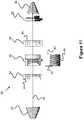
- Heater 40will heat up as current flows through it. Referring to Figure 11 , this heat will initially cause the monofilament wire 50 to stretch, in turn increasing tension between springs 37 and 38. When the springs 37, 38 and the filament 50 reach a sufficient tension, wire 50 will break, resulting in distal cap 32 and distal coil 38 detaching into the vasculature, as seen in Figure 14 .
- the distal cap 32is preferably mechanically affixed (e.g., via adhesive) to the distal conductive sleeve 35 to prevent it from detaching into the vasculature on its own.
- the components proximal to the cap 32 and distal coili.e. conductive sleeves 34 and 35, insulating sleeve 36
- the capsule members 410 and 416are composed of a material that tolerates relatively high temperatures but does not conduct electricity, such as ceramic.
- the proximal capsule member 416preferably has a conductive element 416A (e.g., platinum) insert molded into the member 416, serving as a connection point for the end of the fuse member 414 and as a connection point to the intermediate coil 404 (e.g., by welding).
- the proximal capsule member 416is preferably welded near the distal end of the intermediate coil 404 so as to make an electrical connection with the coil 404.
- the distal capsule member 410includes metal elements 410A and loop 412 press molded into it, allowing the metal elements 410A to be welded to the inside of the distal coil segment 406.
- the embolic coilis advanced within a catheter, such as any of the catheters described in this specification (e.g., the catheter of Figure 4 ).
- the uninsulated portion of the intermediate segment 404is aligned with a first electrical contact 26A within the catheter 22 and the uninsulated portion of the proximal segment 402 is aligned with a second electrical contact 26B.
- a circuitis completed through the second electrical contact 26B, the fuse link 418, into the fuse 414, through conductive element 416A, into the intermediate coil segment 404, and finally into the first electrical contact 26A.
- a power supply and interface devicecan sense alignment via completion of the circuit (e.g., via application of a low level of current).
- the components of the releasable joint 400are all composed of material that can withstand about 700 degrees Celsius for 45 minutes (e.g., insulating ceramic materials and titanium based coatings). This allows an entire embolic device to be created with one or more of the releasable joints 400, then heat set into secondary shapes without damaging the components of the joints 400. Additionally, since the non-coil components are located within the coil segments, there may be less friction or ratcheting between the joints and the catheter and/or catheter's electrical contacts.
Landscapes
- Health & Medical Sciences (AREA)
- Life Sciences & Earth Sciences (AREA)
- Animal Behavior & Ethology (AREA)
- Veterinary Medicine (AREA)
- Public Health (AREA)
- Engineering & Computer Science (AREA)
- Biomedical Technology (AREA)
- Heart & Thoracic Surgery (AREA)
- General Health & Medical Sciences (AREA)
- Surgery (AREA)
- Biophysics (AREA)
- Pulmonology (AREA)
- Anesthesiology (AREA)
- Hematology (AREA)
- Molecular Biology (AREA)
- Medical Informatics (AREA)
- Nuclear Medicine, Radiotherapy & Molecular Imaging (AREA)
- Vascular Medicine (AREA)
- Reproductive Health (AREA)
- Surgical Instruments (AREA)
- Media Introduction/Drainage Providing Device (AREA)
Description
- This application claims priority to
U.S. Provisional Application Serial No. 61/919,669 filed December 20, 2013 - Vessel occlusion is often necessary in a variety of cases including but not limited to treatment of aneurysms, atrial septal defects, patent foramen ovale, left atrial appendage occlusion, patent ductus arteriosis, fistula, arterio-venous malformations, fallopian tube occlusion for the purposes of sterilization, and occlusion in the peripheral vasculature. One method of vessel occlusion involves filling the vessel or malformation or aneurysm with coils for the purposes of embolization. Such coils may be called embolic coils. Typical embolic coil technologies utilize a set length of coil so the coils may be introduced in various stages. If the coil is too short to sufficiently pack the vessel/malformation/aneurysm multiple coils may need to be introduced, which can lengthen procedure time. If the coil is too long for the space there is a danger of the coil protruding out of the vessel/malformation/aneurysm. The use of a variable length detachable coil would allow a precise amount of embolic coil to be placed within the vessel/malformation/aneurysm.
- Guidewires are typically used to track a delivery device to a particular target area within the vasculature. Navigation through tortuous anatomy can be difficult. A guidewire that could manipulate its shape within the vasculature to aid in navigation and tracking would thus be beneficial.
- A catheter sensor system may be used to interact with an embolic coil in order to detach the embolic coil at one or more points along the coil. The catheter sensor system may also be used with other devices such as a guidewire. The guidewire may bend in response to an impulse conveyed via electrical contact with the one or more catheter sensors.
- Document
US2013296917 discloses an embolic coil delivery system comprising a catheter including a first contact and a second contact, an embolic coil including two coil segments separated by a link, wherein the link includes a proximal conductive sleeve, a distal conductive sleeve, and a monofilament between the proximal and the distal conductive sleeves, the monofilament being degradable. - The invention concerns an embolic coil delivery system according to
independent claim 1. Preferred embodiments are defined in the dependent claims. - In another embodiment an embolic coil includes coil segments comprising the same type of coil.
- In another embodiment an embolic coil includes coil segments comprising various types of coil.
- In another embodiment a guidewire steering system comprises a bimetallic guidewire and a catheter with electrical contacts.
- In another embodiment a guidewire steering system comprises a bimetallic guidewire and heater coil.
- In another embodiment a combined embolic coil detachment and guidewire steering system comprises a catheter with electric contacts used to interface with an embolic coil and/or guidewire.
- In another embodiment a microcatheter includes electrical contacts which interact with devices placed through the microcatheter.
- In another example, not part of the invention, an embolic chain comprises a plurality of spheres fixed on a monofilament. The spheres can include a hollow lumen filed with a material such as a drug that can be distributed through an aperture to the lumen. The embolic chain can be detached by applying electric current (e.g., from contact within a catheter) between two adjacent spheres, causing the spheres to heat and thereby breaking the monofilament.
- In another embodiment, an embolic coil is in electric communication with one terminal of a power supply and a contact on a catheter is in electric communication with another terminal of a power supply. When the catheter's contact aligns with a joint on the embolic coil and the power supply is activated, the joint breaks, releasing a portion of the embolic coil.
- In another embodiment, an embolic coil is in electric communication with one terminal of a power supply and a contact on a catheter is in electric communication with another terminal of a power supply. When the power supply is activated, an electrolytically severable joint positioned outside of the catheter is degraded, severing the embolic coil. The catheter is further filled with a non-conducting fluid to prevent any joints still within the catheter from also degrading.
- In another embodiment, a catheter includes a heating coil formed by laser cutting a metal hypotube or a thin, flat, metal sheet. Several heating coils can be arranged in overlapping layers within each other, axially in series along the catheter's length, or in parallel, adjacent to each other.
Figure 1 illustrates an embolic coil used in an embolic coil detachment system.Figure 2 illustrates an embolic coil detachment system utilizing the embolic coil ofFigure 1 .Figure 2a shows the heater of the embolic coil detachment system ofFigure 2 .Figure 3 illustrates another embolic coil used in an embolic coil detachment system.Figures 4-7 illustrate an embolic coil detachment system utilizing the embolic coil ofFigure 3 .Figure 8 illustrate another embolic coil detachment system utilizing the embolic coil ofFigure 3 .Figures 9-12 illustrate an embolic coil utilizing a detachable link used in an embolic coil detachment system.Figures 13-16 illustrate an embolic coil detachment system utilizing the embolic coil ofFigures 9-12 .Figures 17-20 illustrate a contact that can be used in an embolic coil detachment system.Figures 21-22 illustrate an embolic chain of spheres.Figure 23 illustrates a severable joint for an embolic coil.Figure 24 illustrates an embolic coil with a plurality of joints that can be severed by electrical contact with a catheter's electrode.Figure 25 illustrates a catheter that breaks an electrolytic joint on an embolic coil.Figure 26 illustrates a catheter used in a guidewire steering systemFigures 27-28 illustrate the catheter fromFigure 26 with a guidewire being delivered through the catheterFigure 29 illustrates a catheter used in a combined embolic coil detachment and guidewire steering systemFigure 30 illustrates the catheter fromFigure 29 used with an embolic coilFigures 31-32 illustrate the catheter fromFigure 29 used with a guidewireFigures 33-34 illustrate a bendable guidewire within the vasculature.Figure 35 illustrates a heater coil for a catheter system.Figure 36 illustrates a flat, laser cut sheet of material that can be used to form the heater coil ofFigure 35 .Figures 37-39 illustrate various configurations of multiple heaters fromFigure 35 within a catheter.Figure 40 illustrates another embodiment of an embolic device having a detachable joint.Figure 41 illustrates another embodiment of an embolic device having a detachable joint.Figures 42-45 illustrates various components of the detachment system of the embolic device ofFigure 9 .Figure 46 illustrates another embodiment of an embolic device having a detachable joint.Figure 47 illustrates a heater coil of the detachment system ofFigure 46 .Figure 48 illustrates another embodiment of an embolic device having a detachable joint.Figures 49-50 illustrate another embodiment of an embolic device having a detachable joint.Figure 51 illustrates a piston member of the detachment system of the catheter fromFigures 49-50 .Figure 52 illustrates another embodiment of an embolic device having a detachable joint.Figures 53-54 illustrate cross sectional views of the detachment system ofFigure 20 .Figure 55 illustrates another embodiment of an embolic device having a detachable joint.Figures 56-65 illustrate various components of the detachment system from the catheter ofFigure 55 .Figure 66 illustrates another embodiment of an embolic device having a detachable joint.Figures 67-68 illustrate another embodiment of an embolic device having a detachable joint.Figures 69-70 illustrate another embodiment of an embolic device having a detachable joint.- Specific embodiments of the invention will now be described with reference to the accompanying drawings. This invention may, however, be embodied in many different forms and should not be construed as limited to the embodiments set forth herein; rather, these embodiments are provided so that this disclosure will be thorough and complete, and will fully convey the scope of the invention to those skilled in the art. The terminology used in the detailed description of the embodiments illustrated in the accompanying drawings is not intended to be limiting of the invention. In the drawings, like numbers refer to like elements.
- Unless otherwise defined, all terms (including technical and scientific terms) used herein have the same meaning as commonly understood by one of ordinary skill in the art to which this invention belongs. It will be further understood that terms, such as those defined in commonly used dictionaries, should be interpreted as having a meaning that is consistent with their meaning in the context of the relevant art and will not be interpreted in an idealized or overly formal sense unless expressly so defined herein.
US8182506 andUS20060200192 describe a detachment system. The user interface described later may utilize the principles mentioned in these references.- Please note with respect to
Figures 1-8 elements on the left side of the drawings are considered distal relative to the elements on the right side of the drawings (and, consequently, elements on the right side of the drawings are considered proximal relative to the elements on the left side of the drawings). - An embolic coil detachment system according to the invention is shown in
figures 1-20 and includes an embolic coil and a detachment system.Figure 1 illustrates acoil 10 used in an embolic coil detachment system. Thecoil 10 includes a plurality ofcoil segments 12 separated bylinks 14 between the segments. Thelinks 14 are degradable and, when the links are degraded sufficiently, thecoil segment 12 detaches from the rest ofcoil 10. - A proximal pusher 20 (e.g., an elongated member attached to the
coil 10 so as to push thecoil 10 out of a catheter) is connected to a proximal end of thecoil 10 and may optionally include anotherlink 14 between the proximal-most coil segment and the pusher. In one example, thelinks 14 ofFigure 1 are thermolytically degradable.Links 14 may be made of a material which has a lower melting point than the material comprising the coil. In one example, a polymer is used forlinks 14. Thoughlinks 14 are shown as being a plurality of strands, a thicker solid link (such as that shown inlink 14 ofFigure 3 ), a single strand, or a tubular member may also be used. Figure 2 illustrates a detachment system that can be used with theembolic coil 10 ofFigure 1 . The detachment system includes aheater 16 which is located at a distal end ofwire track member 18, which is preferably sized to locate theheater 16 near a distal end of a catheter. As previously discussed, theheater 16 can melt or degrade thelinks 14 to cause detachment between two of thevarious coil segments 12 fromcoil 10.- A proximal portion of the
wire track member 18 can be located within a passage throughpusher 20, thus allowing one to push or pullpusher 20 independently of any movement ofwire track member 18. The material for thewire track member 18 could be any variety of metal or polymer including but not limited to stainless steel, nitinol, polyethylene, polyimide, or any combination of such materials. Thewire track member 18 preferably includes negative and positive electricalcurrent lines 19 to transfer current to theheater 16. The proximal end of thewire track member 18 can be connected to a battery or voltage source with a positive and negative terminal and a mechanism to selectively activate the power supply. Heater 16 can be a wire coil and is preferably made of a high electrical resistive material, such as platinum or tantalum. The outer diameter ofwire track member 18 andheater 16 are preferably small enough to allow the inner diameter ofcoil 10 to slide there over, while still fitting within a typical microcatheter. For example, for a microcatheter with a lumen that is about 0,017" (0,43mm) the maximum outer diameter of thecoil 10 may be about 0,016" (0,41mm). Assuming a relatively large filar diameter of 0,003" (0.08mm), thewire track member 18 may have an outer diameter less than or equal to about 0,008" (0,20mm). The optimal size of the wire track may be as large as possible while not sacrificing the flexibility of the system. In one example, thewire track member 18 could range from 0.003" (0,08mm) to 0.012" (0,30mm) in outer diameter.Figure 2a shows a closer view of theheater 16 andwire track member 18. One of thecurrent lines 19 connects to the proximal part of theheater 16 and anothercurrent line 19 connects to the distal part of theheater 16 to provide an outgoing and incoming flow path for the current. In this respect, the current can be selectively applied to theheater 16, generating heat. When theheater 16 is aligned with one of thelinks 14 of thecoil 10, theheater 16 heats thelink 14 from an inside of thecoil 10, causing the twoadjacent coil segments 12 to disconnect from each other.- The
coil 10 comprising the coil segments may be made of a radiopaque biocompatible material. In one example it is made from 92/8 ratio platinum/tungsten material. For the coil shown inFigure 1 , thecoil segments 12 may be connected withlinks 14 where the links are a monofilament made of a material such as PET (polyethylene terephthalate), Engage polymer, or PTFE (polytetrafluoroethylene). These monofilament junctions become severed by the heat generated byheater 16 when the junction is aligned correctly with the heater and when the appropriate energy is supplied to the heater. Alternatively, the links may have a tubular form where the heat generated from theheater 16 melts the linkages. In another alternate embodiment, thelinks 14 can be completely solid (i.e., a filled, cylindrical shape) as seen inFigure 3 . Pusher 20 may be comprised of a hypotube of similar dimensions to thecoil 10 to allow easy tracking over thewire track 18 and easy tracking within the delivery device (e.g., microcatheter). Thepusher 20 can be made of a metal such as stainless steel or Nitinol, or a polymer such as polyethylene or polyimide.Figure 3 illustrates anothercoil 11 which can be used in another detachment system. Thesolid links 15 are shown as being thicker than the monofilament links 14 shown inFigure 1 . The coil links 15 may be interchangeable with the links 14 (i.e. both of the links shown inFigure 1 andFigure 3 can be used on asingle coil 10, 11) depending on the properties of the coil detachment system. The figures are shown as representations of the coil embodiments and coil detachment system embodiments. Since thelinks 14 are preferably completely solid (or alternately cylindrical with a hollow passage), it may not be desirable to use them with thewire track member 18 andheater 16 ofFigure 2a . Therefore, it may be desirable to use a heating mechanism via a microcatheter disposed over thecoil 11.Figure 4 illustrates amicrocatheter 22 used in a coil detachment system to check or determine alignment of theembolic coil 11. The detachment system includes amicrocatheter 22 withelectrical contacts 26 near the distal end of thecatheter 22. InFigure 4 these contacts are shown as a pair of current carrying elements made of any electrically conductive material (one at a more proximal and one at a more distal location). Each of thesecontacts 26 can be rings extending around the interior circumference of the catheter's inner passage or can be one or more points or arcs that only contact a small portion of thecoil 11. Other electrical contacts (a heater coil, electrodes, etc.) can also be used.- The detachment system may be used to not only check the alignment of the
embolic coil 11, but initiate a detachment operation if the alignment is correct. For example, the alignment may be determined by measuring a value such as resistance, capacitance, resonant frequency, and/or metal detection between theproximal contact 26A and thedistal contact 26. Thecontacts 26 are connected to a control system at the proximal end of the device viawires 28. Thewires 28 extend between the proximal set ofcontacts 26A to the control system, and the distal set ofcontacts 26B, back to the control system. The control system can measure the correct alignment (discussed further below), as well as initiate a detachment sequence (i.e. heating to sever the linkage). Figures 5-7 show thecatheter 25 ofFigure 4 used to check the appropriate alignment of theembolic coil 26. Since theembolic coil 10 is composed of a series ofsegments 12 interconnected bylinks 14, the axial alignment is determined based on the measured values (e.g., resistance) between the two sets ofelectrical contacts 26.- For example, in
Figure 5 , only one portion of thecoil segment 12 contacts both theproximal contact 26A anddistal contact 26B, allowing measurement of a first resistance value based on the material properties of thecoil segment 12. InFigure 6 ,linkage 14 contacts thedistal contact 26B, whilesegment 12 contacts theproximal contact 26A, and therefore a second resistance value is measured based on the material properties oflink 14. InFigure 7 , thedistal contact 26B contacts thelinkage 14 and theproximal contact 26A contacts thesegment 12, therefore providing a third resistance measurement. - In one example, the desired axial alignment within the
catheter 25 is shown inFigure 6 (e.g., detected by the second resistance value), where degradation oflink 14 could be initiated to separate thecoil segment 12 from the rest of thecoil 11. In one example, when desired alignment is measured, a signal could be relayed to the user (i.e. a light and/or sound on a user interface device). The user could interact with the interface (e.g., press a button) to initiate detachment. - In one example,
contacts 26 can also relay heat to severlink 14 when desired. In another example, an alternate heat system (e.g., a heater coil within the catheter 25) coupled to the control system can be used to severlink 14 when desired. Once the user presses the button, detachment is automatically initiated once the proper resistance valued is measured based on the position of theembolic coil 11 relative to thecontacts 26. In addition to thermolytic detachment, electrolytic or other detachment mechanism could also be used to severlink 14. Contacts 26, in addition to measuring a value (e.g., resistance) to check the proper alignment of the coil components, can also transmit or cause heat to initiate detachment via degradation oflinks 14. For example, thecontacts 26 can supply sufficient current to heat up twosegments 12 on each side of alink 14, causing thesegments 12 melt thelink 14. Specifically, the circuit extends between the control system, through onewire 28, through one set ofcontacts 26, through a portion of the embolic coil (that portion which contacts between the two wires), through the other set ofcontacts 26, through theother wire 28, and back to the control system. One of thewires 28 can be attached to a positive terminal in a voltage source in the control system, whereas theother wire 28 can be attached to a negative terminal of the voltage source in the control system to complete the circuit. In another embodiment, each of the contacts can be connected to additional wires that selectively cause each of the contacts to themselves generate heat.Figure 8 illustrates acatheter 27 similar to thecatheter 25 shown inFigure 4 , except thecontacts catheter 27. Thecontacts wires 28 to positive and negative terminals of a control system similar to the one described earlier, allowing capacitance to be measured. Depending on the dielectric constant of the material passing between theparallel contacts coil segment 12, while another dielectric constant value will be observed for thelink 14, since they are made of different materials. When a particular capacitance value is measured by the control system based on the measured dielectric constant oflink 14, a detachment sequence similar to the one described earlier can be initiated.- Please note with respect to
Figures 9-16 elements on the right side of the drawings are considered distal relative to the elements on the left side of the drawings (and, consequently, elements on the left side of the drawings are considered proximal relative to the elements on the right side of the drawings). Figure 9 illustrates a detachment system utilizing adetachable link 30 that connects twoadjacent coil segments 12. Thedetachable link 30 comprises a capsulelike portion containing a degradable element.Figure 10 shows a closer view oflink 30, whileFigure 11 offers an exploded view of thelink 30 shown inFigure 10 .Link 30 includes an insulatingsleeve 36 which can be made of any biocompatible non-conductive material. Polymer, such as polyimide, or a ceramic are examples of materials that can be used for the insulating sleeve.- Two conductive cylinders or
sleeves sleeve 36 via adhesive or glue. Theconductive sleeves Heater 40, which can be a coil of wire, spans the area between the proximal and distalconductive sleeves sleeves sleeves conductive sleeves 34. 35 and throughheater 40, causing theheater 40 generate heat. In one example,heater 40 is positioned over insulatingsleeve 36 and in another example,heater 40 is located within insulatingsleeve 36. In both examples theheater 40 would preferably not have significant contact with the insulatingsleeve 36 so as to not dissipate the heat that can build up withinheater 40. The heater is preferably made of a biocompatible material which also has high electrical resistance. In one example the heater is made of a 92/8 ratio platinum/tungsten material and is a coil.Cap 32 is located distal of distalconductive sleeve 35 and is affixed to a distally locatedcoil segment 12. In one example, thecap 32 may also be made of a 92/8 ratio platinum/tungsten material. Anotherembolic coil segment 12 is affixed proximal to the proximalconductive sleeve 34, and, in one example, the distal coil segment is welded to thecap 32 and the proximal coil segment is welded to the proximalconductive sleeve 34.Spring 38 is located distal ofcap 32, while anotherspring 37 is located proximal to the proximalconductive sleeve 34 to provide flexible connection points for amonofilament 50. Themonofilament wire 50, which can be composed of a polymer (e.g., PTFE or Engage), preferably tied to a proximal part of theproximal spring 37 and a distal part of thedistal spring 38, though any type of connection can be used. Preferably there is minimal slack or even some tension in themonofilament 50 when it is tied between the twosprings Figure 12 shows another embodiment of adetachable link 31 used in a coil detachment system, which is similar to that discussed with regard toFigures 10-11 , but includes asingle spring 46 instead of two springs.Spring 46 spans theentire link 31 and is locate within theheater 40. Instead of themonofilament 50 spanning between the two springs, it extends within and throughspring 46. In one example, the monofilament may be tied to a proximal part ofspring 46 and the distal coil segment (which connects to distal cap 32). In another example,spring 46 is located externally of theheater 40.- The detachment
operations utilizing link embolic coil segment 12.Figure 13 shows the embolic coil comprised of variousembolic coil segments 12 and links 31 (thoughlink 30 could also be used) between said segments. The number ofsegments 12 andlinks 31 shown in the figures are for illustrative purposes only. Thelinks 30 include proximalconductive sleeve 34, distalconductive sleeve 35, andheater 40 -- among other components. The coil is delivered through a microcatheter ordelivery device 22. - The delivery device includes
contacts contact 54 has a negative polarity. - As seen in
Figure 13 , whencontact 52 aligns with proximalconductive sleeve 34 andcontact 54 aligns with distalconductive sleeve 34, the circuit is completed, allowing the current to flow throughpositive contact 52, through proximalconductive sleeve 34, throughheater coil 40, through distalconductive sleeve 35, throughcontact 54 and back to the control system/voltage source. In one example a user interface may house the control system/voltage source that interfaces with the system described. A visual or audio cue (i.e. a light and/or sound) can be provided when proper alignment betweencontacts conductive sleeves Heater 40 will heat up as current flows through it. Referring toFigure 11 , this heat will initially cause themonofilament wire 50 to stretch, in turn increasing tension betweensprings springs filament 50 reach a sufficient tension,wire 50 will break, resulting indistal cap 32 anddistal coil 38 detaching into the vasculature, as seen inFigure 14 . Note, thedistal cap 32 is preferably mechanically affixed (e.g., via adhesive) to the distalconductive sleeve 35 to prevent it from detaching into the vasculature on its own. The components proximal to thecap 32 and distal coil (i.e.conductive sleeves - If another detachment sequence is initiated at another location of the embolic coil, these other components (i.e. distal
conductive sleeve 35, insulatingsleeve 36, proximalconductive sleeve 34, etc.) will then detach into the vasculature when the next detachment sequence initiates. This sequence is illustrated inFigures 13-16 . InFigure 13 , the first detachment sequence is initiated, thus separatingdistal cap 32 and thedistal coil segment 12 from the rest of the coil as shown inFigure 14 . InFigure 15 the coil is pushed until the next detachment zone or link 31 is lined up with thecontacts Figure 16 . - Preferably, all the link components are biocompatible, either being comprised of polymers (
monofilament 50, insulating sleeve 36) or a biocompatible metal (heater 42,conductive sleeves cap 32, coil segment 12). For thelink embodiment 31 shown inFigure 12 , the heat generated fromheater 40 causes themonofilament wire 50 to expand and causes theunitary spring 46 which the wire is housed in to stretch until said wire breaks. Where the distal end ofmonofilament 50 is attached to the distalembolic coil segment 12, the distalembolic coil segment 12 will then detach. - In another embodiment, another system can be utilized to energize
heater 40. This system can be coupled with the same user interface. This parallel system could utilize another set of circuitry to provide heat toheater 40 and promote detachment. In one example, the detachment system provides a cue to the user when the link is aligned appropriate with the contact. The user could then take an action (i.e. press a button on the user interface) which would engage the parallel system to heatheater 40 and detach the coil segment. - In another embodiment no cue is provided to the user when the link is appropriately aligned. Instead, the user may take an action (i.e. press a button on the user interface) when detachment is desired. Then when the link is appropriately aligned the detachment sequence will commence. The heating of
heater 40 could, as described earlier, be part of a parallel or integrated system. - The coil detachment systems shown in
Figures 4-7 ,8 ,13-16 illustrate a type of intelligent microcatheter, wheremicrocatheter 22 has means near the distal end of the microcatheter to read the embolic coil position via contacts. Other embodiments of the various systems described could utilize a hypotube, smaller microcatheter, or other delivery device delivered through a microcatheter. The coil would be delivered through this hypotube/smaller microcatheter/inner delivery device, where the hypotube/smaller microcatheter/inner delivery device would have the contacts to read the embolic coil position. Figures 17 and 18 show one embodiment ofcontacts contacts contacts conductive tips 56 comprised of a conductive material such as gold and are best seen in the top, profile view ofFigure 18 . As the embolic coil passes by, thetips 56 contact different areas, providing electrical communication with therings - For the correct detachment alignment, the
tips 56 line up withconductive sleeves contact 54 can be negative, or vice-versa. Figure 19 showscontacts microcatheter 22. In this figure thecontacts Figure 20 shows the system as an embolic coil passes through. Thecontacts contacts tips 56. Thus when theconductive sleeves contacts - In one embodiment, the
coil segments 12 that make up the embolic coil (e.g., 10 or 11) may utilize various types of coil. For example, often when filling aneurysms a relatively firmer framing coil is deployed first to frame the periphery of the aneurysm. A relatively softer filling coil is then used to fill the space within the aneurysm. An even softer finishing coil is finally used to fill the small spaces left within the space of the aneurysm. - An embolic coil used in the embolic coil detachment system could utilize some segments of the embolic coil as framing coils, some segments as filling coils, and some segments as finishing coils. In one example, the distal most coil segment would be a framing coil, the next-distal most segment would be a filling coil, and the most proximal segment would be a finishing coil. In another example, the distal most coil segment would be would be a framing coil and the next segment would be a filling coil. In another example, the distal most coil segment would be a filling coil and the next segment would be a finishing coil. Alternatively, various combinations of framing, filling, and finishing coils could be used as coil segments of the embolic coil. Operation time could be sped up considerably by having one embolic coil with various coil segments comprising the different types of coils necessary for aneurysm/malformation treatment.
- In another embodiment the coil segments comprising the embolic coil may utilize the same type of coil. In one example one of the embolic coils could be comprised of only framing coils, another only of filling, another only of finishing coils. The ability to detach the coil at various points would customize the coil length to the specific aneurysm/malformation volume, at which time the next type of coil could be introduced if necessary. In one example, a first embolic coil utilizes framing coil segments. This is introduced first, and then detached at the appropriate detachment zone when desired. A second embolic coil utilizing filling coil segments is then used and detached at the appropriate detachment zone when desired. Finally, a third embolic coil utilizing finishing coil segments is then used and detached at the appropriate detachment zone when desired.
- Various methods of delivering and/or utilizing an embolic coil and/or an embolic coil detachment system are also contemplated. A method of delivering an embolic coil may utilize providing an embolic coil with detachment regions, delivering such a coil through a delivery device, and initiating a detachment sequence utilizing the detachment system to detach all or a portion of the coil in the vasculature. A method of utilizing the detachment system may involve providing a coil with variable detachment regions, then utilizing a detachment sequence when appropriate to detach all or a portion of the coil within the vasculature. Indication means may optionally be provided to alert the user when the detachment regions are properly aligned.
- Other methods contemplated include providing an embolic coil having multiple coil segments wherein each segment comprises a unique type of coil (i.e. framing, filling, or finishing coils), delivering this coil through a delivery device, and selectively detaching each of the coil types utilizing the detachment system. Another method could include providing various embolic coils where each coil is comprised of a different type of coil (i.e. one coil having only framing coil segments, another coil having only filling coil segments, another coil having only finishing coil segments). The first coil is delivered through the delivery device, and a detachment sequence is initiated when desired. The next coil is then delivered through the delivery device, and a detachment is initiated when desired, and so-forth.
- The methods discussed are not intending to be limiting and only highlight examples of how the devices, techniques, and embodiments described above could also utilize various methods of operation.
Figures 21 and22 illustrate an example of a detachableembolic sphere chain 100 that can be used similarly to the previously discussed embolic coils. Preferably, eachsphere 102 includes apassage 106 that extends there through, allowing a monofilament ortether member 108 to pass through. In one embodiment, thespheres 102 can be anchored to themonofilament 108 by injecting adhesive 112 throughpassage 104, which opens to themonofilament passage 106 and thereby binds to both thesphere 102 andmonofilament 108. Preferably, a plurality ofspheres 102 are fixed on amonofilament 108, adjacent and in contact with each other.- As best seen in
Figure 22 , thespheres 102 are hollow, forming an internal cavity orlumen 102A which can contain hydrogels, foams, and/or drugs that can be released in a patient viaaperture 110. Various aspects of theaperture 110 can be adjusted so as to increase or decrease the speed that the materials are released at. For example, the diameter and depth of theaperture 110 can be adjusted to allow surface tension and capillary action to be the primary mechanism of dispersing material. In this respect, decreasing the aperture size or increasing the aperture depth (i.e., the thickness of the walls of thesphere 102 around the aperture 110) may decrease the rate of delivery of the material. In another example, theaperture 110 can be designed so that at normal atmospheric pressure the material (e.g., drug) is stable within thesphere 102 but when thesphere 102 enters the vasculature of the patient, a gradient is formed that drives the drug out of thesphere 102. In yet another example, a bio-absorbable or biodegradable plug (e.g., PGLA) can be placed into theaperture 110 and can have various thicknesses, depending on the length of time desired for drug delivery to begin (e.g., minutes, hours, days, or even months). - The
spheres 102 may be composed of a metal, such as platinum, palladium, Nitinol, tantalum, or stainless steel. Alternately, thespheres 102 may be composed of a polymer that is plated with a conductive material. For example, where a 0.017' (0,43mm) catheter lumen is used, spheres of 0.013"-0.016" (0,33 mm-0,41mm) diameter may be used. However, this is only offered as an illustrative example and various sizes are contemplated and can be used with various sizes of catheters. - Generally, the
sphere chain 100 can be used with any catheter that includes electrical contacts within its lumen, such as any of the catheter embodiments discussed in this specification. In one embodiment, themonofilament 108 is made of a metal or conductively-plated polymer (e.g., polyimide plated with gold), which allows current to be conducted between two or more spheres 102 (e.g. when the electrical contacts are axially spaced inside the catheter lumen). Hence, current conducts through onesphere 102, into themonofilament 108, though anadjacent sphere 102, and out through a second contact, thereby heating up themonofilament 108, melting the polymer, and separating the twospheres 102. - In another embodiment, a
non-plated polymer monofilament 108 can be used to connect thespheres 102. In this respect, current would pass from onesphere 102 directly to anadjacent sphere 102 via their contact with each other. This current would cause the twospheres 102 to heat up, melting and breaking themonofilament 108. - Though the term sphere is used to describe
elements 102 of thechain 100, other shaped members could alternately be used. For example, cylinders, cubes, hollow saddle shapes, or similar multi-sided shapes. Thus, the term spheres is not meant to be limited to only spherically shapedelements 102. - In one embodiment, the
monofilament 108 is tensioned betweenspheres 102 so as to maintain contact between each of thespheres 102. In another embodiment, themonofilament 108 is not under tension between thespheres 102. - While the
monofilament passage 106 is shown as being straight, a curved passage is also possible. In this regard, the openings of thepassage 106 would not be parallel to each other. It is further contemplated thatseveral spheres 102 withcurved passages 106 can be used to impart a secondary shape to thechain 100. - In another embodiment, the
spheres 102 may further have a wire coil disposed over its outside surface. For example, a single coil may cover theentire chain 100, or a plurality of smaller coils may each cover one or more of thespheres 102. Figure 23 illustrates another embodiment of an embolic coil having a joint 120 that can be selectively released to separate twocoil segments 12 from each other. The joint 120 includes afuse link 124 that is connected to twocontact bands 122. In one embodiment, thefuse link 122 extends through an aperture of thecontact bands 122 and forms aknot 124 to maintain tension between the contacts. In one example, thefuse link 124 is composed of a polyimide monofilament or hypotube that is plated with gold or a similar conducting material. When thecontact bands 122 become aligned with electrical contacts within a catheter (e.g., such as any of the previously described catheters within the present specification), electrical current flows through thefuse link 124, fracturing the plating and breaking the polyimide. Hence, the joint 120 separates, disconnecting onesegment 12 from another. As with other embodiments described in this specification, a microcoil may have several of the joints attachingmultiple coil segments 12, which allow the operator the option of detaching portions of the coilFigure 24 illustrates yet another embodiment of amicrocoil 130 having a plurality of electrolyticallydetachable joints 134. Thejoints 134 preferably include aconductive ring 136 connected to the end of eachcoil segment 12 and anelectrolytic link 138 that couples two of therings 136 together. Themicrocoil 130 is preferably connected to a power source at the proximal end of thepusher 120, whilecontact 137 is connected to a different polarity terminal of the same power source. When themicrocoil 130 is aligned so thatelectrical contacts 137 contact adistal ring 136 of the joint 134, a circuit is created. Specifically, a circuit path begins at a proximal end of thepusher 120, passes through thecoil segments 12, through aproximal ring 136, through theelectrolytic link 138, through thedistal ring 136, throughcontact 137, and back to the power source. When voltage is applied to this circuit, the electrolytic link begins to electrolytically degrade, thereby releasing the portion of themicrocoil 130 that is distal of the joint 134.- In one embodiment, the
microcoil 130 andpusher 120 can be plated in gold or other high conductivity plating material to enhance electrical conductivity. In another embodiment, instead of anelectrolytic link 138, other types of links can be used, such as thermal, thermal-mechanical, RF, mechanical, and optical. - As seen in
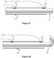
Figure 25 , themicrocoil 130 can also be used with a somewhatdifferent catheter 144 in which the catheter'selectrical contact 146 is located at the distal end of thecatheter 144, creating a circuit between thecontact 146, through the blood of the patient, and into themicrocatheter 130. To prevent all of thelinks 138 still within thecatheter 144 from electrolytically degrading, apurge fluid 140 that does not conduct electricity (e.g., a fluid with about 0 parts-per-million of salts or ions) is pumped into the catheter's lumen. To prevent this non-conducting fluid from interfering with degrading the joint 134 that is immediately distal of the catheter's end, purge holes 142 (or alternately slits or similar shapes) connecting to the catheter's lumen are positioned proximal to contact 146. In this respect, thenon-conducting purge fluid 140 exits thecatheter 144 proximally of thecontact 146, allowing conductivity between the joint 134 and thecontact 146. In one example, thenon-conducting fluid 140 can be iodine, which also allows a user to view the fluid under X-rays and can be more viscous so as to better remain in the catheter. Generally, this embodiment decreases or eliminates the need for precise alignment of and contact between the joint 134 and the contacts within the catheter, since the patient's blood carries a majority of the current. In one example, theelectrolytic link 138 is composed of stainless steel and the coil segments are composed of platinum. Figure 26 illustrates an embodiment of acatheter 150 used for a guidewire delivery system. The catheter includes a proximalelectrical contact 58 and a distalelectrical contact 54, which are oppositely polarized from a proximal power and control system. There may be a user interface (i.e. a button) which the user can use to interface with the control system (e.g., similar to control/power systems described with regard to other embodiment of this specification). Thoughcontact 54 is shown as having a positive polarity andcontact 58 is shown as negative, these can be reversed. The contacts can be similar in design to contacts ofFigures 17-18 .Figures 27-28 show the catheter used with aguidewire 60. Theguidewire 60 is preferably made of a bimetal composite such that theguidewire 60 may bend when exposed to a sufficiently high temperature. In one example, half of the guidewire 60 (i.e., half circle of the guidewire's cross section) is composed of a first metal, while the other half is composed of a second metal with a different coefficient of expansion. When current is applied to theguidewire 60 viacontacts guidewire 60 increases in temperature. Since the metals expand at different rates, the guidewire bends in one direction. This bending can be used to help steer theguidewire 60 and catheter through the vasculature by bending theguidewire 60, rotating theguidewire 60 towards a desired direction, and further advancing the guidewire. In one example, only a distal portion of theguidewire 60 is composed of two metals on each side. In another example, theentire guidewire 60 comprises two halves that each are different metals.- In one method of use example, the
catheter 150 may reach a bifurcation in a vessel and the steering system can be enabled (via the user interface) to cause the distal end of theguidewire 60 to bend. The user can then torque or rotate thecatheter 150 and guidewire 60 so the bend is directed in the direction he or she desires to steer the catheter (seeFigures 33-34 ). In order to create a sufficiently high temperature increase to cause the guidewire to bend, the contacts are preferably spaced out to allow a higher current flow path to increase heat transmission. In one example, this spacing is from about 0.5 to 3 cm. Factors such as the materials used and electrical impulse utilized can affect the required spacing between the contacts. Figure 29 shows acatheter 152 used in a combined guidewire-embolic coil system. The catheter utilizes threecontacts distal contacts contacts guidewire 60.Contacts distal-most contact 54 has an opposing polarity. Thoughcontact 54 is shown as being positively polarized and 52, 58 are shown as being negatively polarized, it could be switched such that 54 has a negative polarity and 52, 58 have a positive polarity. In one example, a user interface could have two buttons to interact with the guidewire system or the embolic coil detachment system. Thecontacts Figures 17-18 .- In another embodiment a catheter/delivery device (i.e. sheath, hypotube, microcatheter, or catheter) utilizes electrical contacts. The catheter can be thought of as an intelligent catheter since it comprises electrical contacts which interact with devices placed through said catheter. The contacts are connected to an electric system to polarize the contacts. The contacts can be used to interact with devices which pass through the catheter (i.e. the embolic coil(s) and/or guidewire previously described). The user may have an interface to initiate a sequence (i.e. embolic coil detachment or guidewire manipulation) via the user interface previous described. In one example, for a combined embolic coil detachment and steerable guidewire system the user interface would have two buttons, one to detach the coil and another to bend the guidewire to aid in steering the delivery system. Hitting one button would send an impulse through the circuitry of the embolic coil detachment system, hitting the other button would send an impulse through the circuitry of the the guidewire system. The intelligent microcatheter could utilize any of the contact structures shown and described in
Figures 4 ,8 ,13 ,21 ,24 . Figure 30 shows the combined system used with an embolic coil.Contacts Figure 31 shows the combined system used with a guidewire.Contacts contact tips 56. In another example, the guidewire has enlarged diameter regions at selective areas in order to interface with the contact tips.- In another embodiment,
contacts proximal contact 58. In this embodiment, the guidewire would not need such a lengthy current flow path within the distal portion of the guidewire to cause the guidewire to bend, such that the additionalproximal contact 56 is not necessary. The materials used in the bimetal composite and impulse used to generate the current are properties that could minimize the current flow path needed through the guidewire to cause the distal end of the guidewire to bend, which would be useful in this particular embodiment. - In another embodiment in lieu of a contact system, the guidewire itself could have a heater coil placed over the distal end of said guidewire. One end of the coil would have a positive polarity, the other end would have a negative polarity. A user interface would be coupled to the proximal end of the system, and a user could interact with the system to generate an impulse to send current through the heater coil to heat the distal tip of the guidewire to cause it to deflect. The user could then torque proximal end of the system to align the guidewire in a desired direction to aid in navigating the catheter through the vasculature. Alternatively, the guidewire has a heater coil placed over the distal end of the guidewire and the heater coil may electrically interact with a contact system built into the catheter (as described earlier) in order to heat the coil to cause deflection of the distal end of the guidewire. The heater coil would contact the electrical contacts of the catheter, the contacts are coupled to a user interface so the user could send an impulse through the system when desired. When the impulse is sent, the guidewire deflects in response to the heat generated via the heater coil, and the bent guidewire is then used to navigate the catheter.
- In another embodiment in lieu of the heater coil placed over the distal tip of the guidewire, the microcatheter could have an integrated heater coil within the distal portion of the microcatheter. One end of the integrated heater coil would have a positive polarity, the other end would have a negative polarity. The coil could be integrated into a user interface coupled to the proximal end of the system, and a user could interact with the system to generate an impulse to send current through the heater coil. The heater coil could sit in close proximity to, or have direct contact with, the guidewire. When the guidewire sits at the distal end of the catheter, the user could heat the heater coil which causes the distal tip of the guidewire to deflect. The user could then torque proximal end of the system to align the guidewire in a desired direction to aid in navigating the catheter through the vasculature.
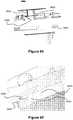
Figure 35 illustrates an embodiment of aheater coil 160 comprised of a plurality of adjacentstraight segments 160B that are connected to each other by a plurality of 180 degree curves. The pattern terminates withends 160A that are connected to wires or similar conducting members that ultimately connect to a power supply and control system.- In one embodiment, a hypotube composed of a high resistivity metal, such as platinum, can be laser cut to this "zig-zag" pattern. In another embodiment, a thin sheet of metal can be laser cut in this pattern, then curved into a cylindrical shape. Preferably, the
heater 160 is coated with an insulating material such as polyimide, polyethylene, Teflon, of paralyne. By creating theheating coil 160 by these techniques, the coil can have a relatively small thickness (e.g., such as 0,009" (0,23mm)) while still generating a significant amount of electrical resistance. - Since the
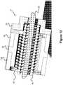
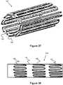
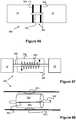
heater coil 160 is relatively thin, one embodiment of a catheter could include a duallayer heater assembly 162 including thecoil 160 and a second, small,inner coil 163 located within it, as seen inFigure 37 . Such anassembly 162 would allow theheater assembly 162 to provide a greater amount of heat to a catheter and/or provide redundancy. Other embodiments may include 3, 4, 5, 6, or more layers of heater coils. The layers of heater coils can each have independent electrical wires to supply power or each of the coils can be chained together in series. Alternatively, a single hypotube (Fig. 36 ) can be rolled into a multiple layer configuration where each successive roll of the hypotube becomes a new layer of the heater. With this configuration, only one set of wires would be needed to heat the whole system since the heater coil is comprised of the same hypotube pattern. Figure 38 illustrates another embodiment of acatheter heater assembly 169 that has a plurality of heater coils staggered along its length to create a plurality of independently operable heater zones. Specifically, thecatheter 164 includes aproximal heater coil 165, amiddle heater coil 166, and adistal heater coil 167, all of which are similar in design tocoil 160. While three coils are shown, such a catheter could include any number coils (e.g., between 1 and 100 coils). The addition of different, discreet heater coils provides redundancy, temperature control, and/or user targeting of a detachment joint of an embolic coil.Figure 39 illustrates a cross sectional view of yet another embodiment in which acatheter 168 has a plurality of heater coils 160 (e.g., 3 coils) that are positioned parallel to each other. Preferably, thecoils 160 are each located within its own catheter lumen passage, thereby allowing several different devices to be used from the same catheter and heated (e.g., for detaching an implant or bending a guidewire as previously described).- As discussed in greater detail below,
Figures 40 -_disclose various additional link or joint embodiments that connect various segments of an embolic device together and that can be selectively separated by a user. Whilecoil portions 12 are described with regard to these embodiments, it should be understood that any embolic device described in this specification could be used in connection with these joints, such asspheres 102. - Turning to
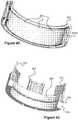
Figure 40 , another embodiment of a detachment joint 252 that connects two portions of an embolic device, such as betweencoil portions 12. The detachment joint 52 is held together with abond material 254 that can degrade (chemically or otherwise) when exposed to liquid such as blood, contrast, saline, or other commonly injected interventional fluids. For example, thebond material 254 may include a salt such as NaCl or similar salts that can dissociate into solution when exposed to liquid. - In one example, the
bond material 254 can be selectively exposed to liquid via an outer electrically controlledmembrane 256. When current is applied via any of the catheter embodiments described in this specification, the membrane allows fluid to enter the joint 252, allowing the bond material 254 (e.g., NaCI) to go into solution and thecoil portions 12 to separate from each other. In one example, theouter membrane 256 operates via the Cassie-Wenzel wetting transitions effect, which is described inBormashenko, Edward, Roman Pogreb, Sagi Balter, and Doron Aurbach. "Electrically Controlled Membranes Exploiting Cassie-Wenzel Wetting Transitions." Scientific Reports 3 (2013). - In another example,
outer membrane portion 256 can be a layer of hydrogel that, when an electric current is passed through via the catheter, causes the hydrogel to give off fluid itself and shrink. Once sufficiently shrunken, the hydrogel will allow fluid from outside the embolic device (e.g., saline from inside the catheter) to enter the joint 252 and degrade thebond material 254. In one embodiment, the hydrogel alone is used. In another embodiment, the hydrogel has a permeable film or layer over it. - In another example, the
outer membrane 256 may be a thin film that melts or degrades when current from the catheter is applied to it. For example, this film could be composed of a polymer such as polyurethane or polyolefin with a melting point sufficient to melt via activation of the heater. - In alternate embodiments, the
inner surface 255 of the joint 252 could be configured to selectively allow passage of fluid (e.g., saline or contrast) from theinner passage 253 to thebond material 254. This selective passage of fluid can be accomplished via any of the mechanisms discussed with regard toouter member 256, and can be used alone or in addition to the outer membrane 256 (i.e., both membranes can selectively allow passage of fluid). Figures 41-45 illustrate various aspects of anembolic device 270 havingcoil portions 12 that are detachable from each other via joint 272. Generally, the joint 272 includes a plurality ofheating elements 274 attached to a distal end of acoil portion 12 that, when activated, meltadhesive members 284, thereby releasing theadjacent coil portion 12.- As best seen in
Figure 42 , theadhesive members 284 are located within agroove 282A of adistal ring 282, which is fixed to a proximal end of anothercoil portion 12. Theheating elements 274 are also positioned in thegroove 282A, such that theadhesive members 284 fix or secure theheating elements 274 to thedistal ring 282, thereby maintaining the twoadjacent coil portions 12 together. - In one embodiment, the
heating elements 274 form a plurality of generally rectangular shapes, though a variety of different shapes are possible, such as a single square or a plurality of circular loops. - Electrical current is distributed to each of the heating elements 74 via a distal
conductive ring 280 and a proximal conductive ring 276 (both of which are separated by insulating layer 278). Each of therings - The
heating elements 274 preferably have afirst end 274A that makes electrical contact with only thedistal ring 280 andsecond end 274B that makes electrical contact with only theproximal ring 276. As seen inFigures 44 and 45 , this arrangement can be accomplished by thefirst end 274A having a relatively small length that permits entry into only one of theapertures 280A of thedistal ring 280, and thesecond end 274B having a relatively long length that extends throughaperture 280, through the apertures of the insulatinglayer 278, and into one of theapertures 276A of theproximal ring 276. Insulatingmembers 281 can be further located on portions of thesecond end 274B located within theaperture 280A of thedistal ring 280, thereby preventing electrical contact that would otherwise prevent current from flowing completely through theheating element 274. Figure 46 illustrates another embodiment of a segmented embolic device 290 with a plurality ofjoints 292 betweenadjacent coil segments 12. The joint 292 is held together by a plurality of tethers ormonofilaments 296 located axially and circumferentially around the wall of the device 290. Eachtether 296 is anchored under tension to bothcoil portions 12 via anchors 98. The anchors can be an adhesive, bonding agent, a distinct element that thetether 296 can be tied to, or similar fastening mechanisms.- The
tethers 296 are preferably broken by aresistive heater 294 located near each of thetethers 296. For example,Figures 46 and 47 illustrate aresistive heater ring 294 that is composed of a plurality ofcoiled portions 294A connected by adjacentcurved regions 294B, so as to form a ring shape. Each of thecoiled portions 294A are preferably coiled around one of thetether members 296, so as to allow efficient heat transfer to thetether members 296. Finally,electric wires heater 294 and each to anelectrical contact ring rings coils 294A heat up and melt or break thetether members 296 and release thecoil portions 12 of the device 290 from each other, thereby releasing a portion of the device into the patient. Figure 48 illustrates another embodiment of an embolic device 300 (e.g., a microcoil) having a plurality ofelectrolytic joints 102 that connect a plurality ofcoil segments 12, such that thedevice 300 can be selectively detached at a plurality of different locations. Specifically, the joint 302 preferably contains aproximal ring 304 and adistal ring 306 that are in contact with a middlesacrificial anode ring 308. A proximal end of a pusher (which is connected to a proximal end of the device 300) is connected to a power supply so as to provide positive current to thering 304, while negative current is supplied via fluid from within thecatheter 300 or through the patient's blood via an electrode in contact with the patient. Therings sacrificial anode ring 308 are selected so as to cause rapid galvanic corrosion of the anode ring 308 (i.e., theanode ring 308 acts as an anode and therings anode ring 308 has sufficiently corroded, thedistal coil portion 12 of the device 300 (including ring 106) disconnect from theproximal coil portion 12.Figures 49-51 illustrate another embodiment of anembolic device 310 having a plurality of mechanical release mechanisms that can selectively detach and release thedevice 310 at various locations along thedevice 310. Specifically, thedevice 310 includes one ormore pistons 314 having apin 316 that moves outward to disengage the mechanical release mechanism. In one example, the mechanical release mechanism includes ahook portion 316A on the distal end of thepin 316 that can be moved from a latched position (Figure 49 ) to an unlatched position (Figure 50 ). However, it should be understood that a variety of different latching mechanisms can be used with thepiston 314.Figure 19 illustrates one possible embodiment of thepiston 314 in which a pressure-resistant housing 322 andcap 320 contain amaterial 324 that expands when heated. Thematerial 324 can be any wax, oil, or similar material with a high enough coefficient of expansion to cause movement of thepiston 314. In another example, thematerial 324 can be mercury, ethanol, or other materials with relatively high coefficients of expansion. When theheater coil 312 is activated, it heats up thepistons 314, causing thematerial 324 to expand within thehousing 322, thereby pushing thepin 316 at least partially out of thehousing 322.Figures 52-54 illustrate another embodiment of anembolic device 330 having a plurality ofmechanical release mechanisms 332 connecting a plurality ofcoil segments 12. Specifically, therelease mechanism 332 includes aproximal ring 334 and adistal ring 336 that are positioned against each other and are connected or held together via a plurality of tether members orfilaments 338. As best seen in the cross sectional view of the ring inFigure 53 , therings rings rings Figure 54 ). This shape change generally increases the distance of the ends of the rings from each other, where thetether members 338 are connected, thereby fracturing or breaking thetether members 338 and allowing thedistal coil portion 12 of thedevice 330 to be disconnected from theproximal coil portion 12.- In one embodiment, the temperature bending behavior of the
rings rings rings rings Figures 55-65 illustrate another embodiment of an embolic device 340 (e.g., a microcoil) having a plurality ofmechanical release mechanisms 342 that connect a plurality ofcoil portions 12 to each other. Themechanical release mechanism 342 preferably includes a heat-activatedspring member 346 that maintains themechanism 342 in a locked state during normal, operational temperatures (e.g., body temperature), but changes shape when heated, either by direct application of current or via an adjacent heater coil, to cause themechanism 342 to unlock, thereby disconnectingadjacent coil portions 12 and releasing a portion of theembolic device 340 into the patient.- In one embodiment, the temperature bending behavior of the
spring member 146 can be created by using a bi-metal design (i.e., a first metal on a first side of thespring member 346 and a second, different metal on the second side of the spring 346). In another embodiment, the shape-changing behavior of thespring member 346 can be created by using a material capable of Martensite/Austenite transitions. For example, thespring member 346 can be composed of Nitinol having a relatively high Austenite finish temperature, such that when current is applied to the spring or a heater coil is activated, thespring member 346 transitions to its Austenite phase, thereby changing shape, as well. - The
spring member 346 of themechanical release mechanism 342 is located on and around abase portion 350. Thespring member 346 is further anchored in place on thebase portion 350 by a firstelongated anchor member 346A at one of its ends, extending intoaperture 350A (best seen inFigure 58 ). Thespring member 346 also includes a secondelongated anchor member 346B that extends into an aperture within the locking ring 348 (best seen inFigure 58 and 59 ). In this respect, thespring member 346 maintains thelocking ring 348 in a first rotational position relative to thebase portion 150 during normal operating temperatures (e.g., body temperature) and rotates thelocking ring 348 when heated (via applied current or heater coil). - The
base portion 350,spring member 346, and lockingring 348 are all preferably contained within anouter housing member 352, which helps maintain the axial positions of these members relative to each other. As best seen inFigure 61 , theouter housing member 352 includes a plurality ofapertures 352A which allow passage of lockingpins 344A on thering 144. - As best seen in
Figures 63-65 , the locking pins 344A pass throughapertures 352A and intoslots 348B on thelocking ring 348. As best seen inFigure 65 , one end of each of theslots 348B include an overhanging portion orlip 348C that is sized and shaped to engage the distal ends of thepins 344A. Specifically, the distal ends of the locking pins 344A have an enlarged diameter relative to the remaining, proximal portions, allowing this distal end to catch on thelip 348C and therefore prevent withdrawal of thepins 344A. Preferably, thespring member 346 is configured to maintain thelocking ring 348 in a rotational position that maintains thelip 348C over distal end of the locking pins 344A. - At the opposite end of the
slot 348B is a ramped surface 148A which assists in pushing the locking pins 344A out of theslot 348B. Specifically, theramp 348A is inclined towards thering 344, such that as thelocking ring 348 rotates, theramp 348A pushes the locking pins 344A axially outward of thehousing 352. In this respect, when thespring member 346 is heated, thelocking ring 348 rotates to disengage the locking pins 344A with thelip 348C and pushes thepins 344A outward. Sincering 344 andbase portion 350 are each attached to either theproximal coil portion 12 ordistal coil portion 12 of thedevice 340, unlocking themechanism 342 separates theportions 12 from each other, detaching and releasing a portion of thedevice 340 from the remaining portion. - Alternately, rotation of the
locking ring 344 of themechanical release mechanism 342 can be performed via a different mechanism. For example, the previously describedpiston 314 could be fixed to the base 350 orhousing 352, as well as thelocking ring 344 so as to rotate thering 344 when heat activates thepiston 314. - Preferably, the
locking ring 344 can be activated by locating thering 344 near a heater coil of a catheter (as previously described) and activating the heater so as to cause detachment. Alternately, the catheter could provide current (e.g., see previously described catheter embodiments) to each side of thering 344 when aligned with electrodes inside the catheter, causing thering 344 to heat up when current is activated. Figure 66 illustrates another embodiment of anembolic device 360 having a plurality offuse release mechanisms 142 that releasably connect a plurality ofcoil segments 12. Specifically, thecoil portions 12 can be held together by one or more (e.g., a plurality) offuse members 362 located near the circumference of thecatheter 360.- The
fuse members 362 are preferably connected to aproximal ring 364 and adistal ring 366. Theproximal ring 364 is connected to thedistal ring 366 via thefuse members 362. Preferably, thefuse member 162 is composed of a material that can be fractured or broken without causing enough heat to damage surrounding tissue in a patient (this breaking value is sometimes referred to as the "clearing I2t" value). In one example, the fuse can be composed of an elongated hypotube of gold plated polyimide material. - When the
rings effuse members 362, thereby fracturing themembers 362 and releasing a portion of thedevice 360. Figures 67 and 68 illustrate another embodiment of a releasable joint 380 for an embolic device having a plurality ofcoil segments 12.Adjacent coil segments 12 are maintained together via a monofilament or tether member 388 (e.g., via tying or via adhesives at each end of the tether 388). As seen best inFigure 67 , aheating coil 386 is located around thetether 384. A first end of theheating coil 386 is connected to a firstconductive housing member 382 while a second end of theheating coil 386 is connected to a secondconductive housing member 384. When thehousing members positive electrode 26C andnegative electrode 26D (e.g., each housing member is contacting a different electrode), current passes through theheating coil 386, generating heat, and breaking or melting thetether 388 to release the portion of the device distal of the joint 380. To prevent the housing from shorting out the electrical system, an insulatinglayer 390 is disposed between the twohousing members housing members electrical contacts - The embodiment of
Figures 67-68 could also be used in the capsule system of Figured 11-12, that is the joint 380 could utilize a spring at both ends of the joint or one spring spanning the entirety of the joint.Monofilament 388 would either be tied to both springs, or tied to two ends of one spring as shown inFigure 12 . When heat is generated, the spring would expand causing the monofilament to break, similar to the embodiments ofFigures 11-12 . Figures 69 (exploded view) and 70 (assembled view) illustrate another embodiment of a releasable joint 400 for an embolic device having a plurality of coil segments. Specifically, theproximal coil segment 402 is releasably connected to thedistal coil segment 406 by anintermediate coil segment 404 and afuse release mechanism 408. Thefuse release mechanism 408 includes aproximal capsule member 416 that includes afuse member 414 and adistal capsule member 410 which includes a fixedloop 412 through which thefuse member 414 passes through to interlock thecapsule members - Preferably, the
capsule members proximal capsule member 416 preferably has aconductive element 416A (e.g., platinum) insert molded into themember 416, serving as a connection point for the end of thefuse member 414 and as a connection point to the intermediate coil 404 (e.g., by welding). Theproximal capsule member 416 is preferably welded near the distal end of theintermediate coil 404 so as to make an electrical connection with thecoil 404. Similarly, thedistal capsule member 410 includesmetal elements 410A andloop 412 press molded into it, allowing themetal elements 410A to be welded to the inside of thedistal coil segment 406. - The
proximal coil segment 402 preferably includes aninsulated portion 402A along its distal portion, such as a ceramic based or titanium based coating. Similarly, theintermediate coil segment 404 includes aninsulated portion 404A along its proximal portion. In an assembled state (e.g.,Figure 70 ), only theinsulated portions proximal segment 402 and theintermediate segment 404 become mechanically connected to each other, but not electrically connected. Finally, afuse link 418 is connected to thefuse 414 and to the uninsulated portion of the proximal segment 402 (e.g., via welding atlocation 418A). - In operation, the embolic coil is advanced within a catheter, such as any of the catheters described in this specification (e.g., the catheter of
Figure 4 ). The uninsulated portion of theintermediate segment 404 is aligned with a firstelectrical contact 26A within thecatheter 22 and the uninsulated portion of theproximal segment 402 is aligned with a secondelectrical contact 26B. At this time, a circuit is completed through the secondelectrical contact 26B, thefuse link 418, into thefuse 414, throughconductive element 416A, into theintermediate coil segment 404, and finally into the firstelectrical contact 26A. A power supply and interface device can sense alignment via completion of the circuit (e.g., via application of a low level of current). When the user wishes to detach thedistal segment 406, a high level of current is applied from the power supply and interface device, causing thefuse 414 to break, thereby releasing thedistal capsule member 410 and thedistal coil segment 406. Since thefuse 414 is broken, the interface and power supply can detect a break in the circuit and can thereby confirm that detachment has occurred. - Preferably, the components of the releasable joint 400 are all composed of material that can withstand about 700 degrees Celsius for 45 minutes (e.g., insulating ceramic materials and titanium based coatings). This allows an entire embolic device to be created with one or more of the
releasable joints 400, then heat set into secondary shapes without damaging the components of thejoints 400. Additionally, since the non-coil components are located within the coil segments, there may be less friction or ratcheting between the joints and the catheter and/or catheter's electrical contacts. - Although the invention has been described in terms of particular embodiments and applications, one of ordinary skill in the art, in light of this teaching, can generate additional embodiments and modifications without exceeding the scope of the claimed invention. Accordingly, it is to be understood that the drawings and descriptions herein are proffered by way of example to facilitate comprehension of the invention and should not be construed to limit the scope thereof.
Claims (14)
- An embolic coil delivery system comprising:a catheter (25) including a first contact (52) and a second contact (54);an embolic coil (10) including two coil segments (12) separated by a link (30), the link (30) including a proximal conductive sleeve (34), a distal conductive sleeve (35), a monofilament (50) connected between the proximal and the distal conductive sleeves (34, 35),characterized in that the embolic coil further comprises a heater connected to the proximal conductive sleeve (34) and the distal conductive sleeve (35);wherein, when the embolic coil is delivered through the catheter, the catheter's first (52) contact is configured to be aligned in electrical communication with the link's proximal (34) conductive sleeve, and the catheter's second (54) contact is configured to be aligned in electrical communication with the link's distal (35) conductive sleeve to complete a circuit, andwherein the monofilament is degradable in response to the circuit being completed and the heater being heated up in response to the circuit being completed, and the two coil segments (12) of the embolic coil (10) are configured to detach from each other in response to the monofilament (50) degrading.
- The embolic coil delivery system of claim 1, wherein the catheter's first (52) and second (54) contacts have opposing polarities.
- The embolic coil delivery system of claim 1, wherein the heater (40) is a heater coil.
- The embolic coil delivery system of claim 1, wherein the monofilament (50) passes through the heater (40).
- The embolic coil delivery system of claim 1, where a spring (46) is placed over the monofilament (50).
- The embolic coil delivery system of claim 1, further comprising a user interface, where a video or audio cue is provided on the user interface when the catheter's first and second contacts (52, 54) are aligned with the link's (30) proximal and distal conductive sleeves (34, 35).
- The embolic coil delivery system of claim 1, further comprising a user interface where a user can press a button on the user interface to initiate a detachment sequence to cause the two segments (12) of the embolic coil (10) to detach from each other.
- The embolic coil delivery system of claim 1, where the link (30) includes an insulating sleeve (36) between the proximal (34) and distal (35) conductive sleeves.
- The embolic coil delivery system of claim 1, where the first and second contacts (52, 54) are embedded in the wall of the catheter.
- The embolic coil delivery system of claim 9, where the first and second contacts (52, 54) include conductive tips (56).
- The embolic coil delivery system of claim 1, where the link (30) includes a cap (32) connected to the distal conductive sleeve (35).
- The embolic coil delivery system of claim 11, wherein the cap detaches with one of the embolic coil segments (12) when the two segments (12) of the embolic coil (10) detach from each other.
- The embolic coil delivery system of claim 11, wherein one embolic coil segment is welded to the proximal conductive sleeve (34) and another embolic coil segment is welded to the cap (32).
- The embolic delivery system of claim 1, wherein proper alignment between the first and second contacts (52, 54) and the proximal and distal conductive sleeves (34, 35) is determined by measuring resistance.
Applications Claiming Priority (2)
| Application Number | Priority Date | Filing Date | Title |
|---|---|---|---|
| US201361919669P | 2013-12-20 | 2013-12-20 | |
| PCT/US2014/071696WO2015095806A2 (en) | 2013-12-20 | 2014-12-19 | Device delivery system |
Publications (3)
| Publication Number | Publication Date |
|---|---|
| EP3082660A2 EP3082660A2 (en) | 2016-10-26 |
| EP3082660A4 EP3082660A4 (en) | 2017-11-15 |
| EP3082660B1true EP3082660B1 (en) | 2020-01-22 |
Family
ID=53398813
Family Applications (1)
| Application Number | Title | Priority Date | Filing Date |
|---|---|---|---|
| EP14870946.2AActiveEP3082660B1 (en) | 2013-12-20 | 2014-12-19 | Device delivery system |
Country Status (8)
| Country | Link |
|---|---|
| US (5) | US9808599B2 (en) |
| EP (1) | EP3082660B1 (en) |
| JP (2) | JP6492087B2 (en) |
| KR (1) | KR102211335B1 (en) |
| CN (1) | CN106029011B (en) |
| AU (1) | AU2014368984B2 (en) |
| CA (1) | CA2934555C (en) |
| WO (1) | WO2015095806A2 (en) |
Families Citing this family (168)
| Publication number | Priority date | Publication date | Assignee | Title |
|---|---|---|---|---|
| EP1951129B1 (en) | 2005-10-19 | 2012-11-21 | Pulsar Vascular, Inc. | Methods and systems for endovascularly clipping and repairing lumen and tissue defects |
| US9402707B2 (en) | 2008-07-22 | 2016-08-02 | Neuravi Limited | Clot capture systems and associated methods |
| WO2010028314A1 (en) | 2008-09-05 | 2010-03-11 | Pulsar Vascular, Inc. | Systems and methods for supporting or occluding a physiological opening or cavity |
| ES2683943T3 (en) | 2010-10-22 | 2018-09-28 | Neuravi Limited | Clot capture and removal system |
| US12076037B2 (en) | 2011-03-09 | 2024-09-03 | Neuravi Limited | Systems and methods to restore perfusion to a vessel |
| EP4566553A3 (en) | 2011-03-09 | 2025-08-06 | Neuravi Limited | A clot retrieval device for removing occlusive clot from a blood vessel |
| US11259824B2 (en) | 2011-03-09 | 2022-03-01 | Neuravi Limited | Clot retrieval device for removing occlusive clot from a blood vessel |
| CN103582460B (en) | 2011-06-03 | 2019-03-19 | 帕尔萨维斯库勒公司 | Aneurysm devices and related systems and methods with additional anchoring mechanism |
| US9119625B2 (en) | 2011-10-05 | 2015-09-01 | Pulsar Vascular, Inc. | Devices, systems and methods for enclosing an anatomical opening |
| US10603157B2 (en) | 2013-03-13 | 2020-03-31 | DePuy Synthes Products, Inc. | Braid implant delivery and retraction device with distal engagement |
| US10561509B2 (en) | 2013-03-13 | 2020-02-18 | DePuy Synthes Products, Inc. | Braided stent with expansion ring and method of delivery |
| ES2708786T3 (en) | 2013-03-14 | 2019-04-11 | Neuravi Ltd | Clot recovery device to remove occlusive clots from a blood vessel |
| US9433429B2 (en) | 2013-03-14 | 2016-09-06 | Neuravi Limited | Clot retrieval devices |
| WO2014140092A2 (en) | 2013-03-14 | 2014-09-18 | Neuravi Limited | Devices and methods for removal of acute blockages from blood vessels |
| KR102211335B1 (en)* | 2013-12-20 | 2021-02-03 | 마이크로벤션, 인코포레이티드 | Device delivery system |
| US10285720B2 (en) | 2014-03-11 | 2019-05-14 | Neuravi Limited | Clot retrieval system for removing occlusive clot from a blood vessel |
| US11076860B2 (en) | 2014-03-31 | 2021-08-03 | DePuy Synthes Products, Inc. | Aneurysm occlusion device |
| US11154302B2 (en) | 2014-03-31 | 2021-10-26 | DePuy Synthes Products, Inc. | Aneurysm occlusion device |
| JP6595513B2 (en) | 2014-06-13 | 2019-10-23 | ニューラヴィ・リミテッド | Device for removal of acute occlusions from blood vessels |
| US10265086B2 (en) | 2014-06-30 | 2019-04-23 | Neuravi Limited | System for removing a clot from a blood vessel |
| US9918718B2 (en) | 2014-08-08 | 2018-03-20 | DePuy Synthes Products, Inc. | Embolic coil delivery system with retractable mechanical release mechanism |
| US10206796B2 (en) | 2014-08-27 | 2019-02-19 | DePuy Synthes Products, Inc. | Multi-strand implant with enhanced radiopacity |
| US9782178B2 (en) | 2014-09-19 | 2017-10-10 | DePuy Synthes Products, Inc. | Vasculature occlusion device detachment system with tapered corewire and heater activated fiber detachment |
| US11253278B2 (en) | 2014-11-26 | 2022-02-22 | Neuravi Limited | Clot retrieval system for removing occlusive clot from a blood vessel |
| EP3682821B1 (en) | 2014-11-26 | 2022-05-11 | Neuravi Limited | A clot retrieval device for removing an occlusive clot from a blood vessel |
| US10617435B2 (en) | 2014-11-26 | 2020-04-14 | Neuravi Limited | Clot retrieval device for removing clot from a blood vessel |
| US10595875B2 (en) | 2014-12-31 | 2020-03-24 | Endostream Medical Ltd. | Device for restricting blood flow to aneurysms |
| US9717503B2 (en)* | 2015-05-11 | 2017-08-01 | Covidien Lp | Electrolytic detachment for implant delivery systems |
| CN108135686B (en)* | 2015-09-10 | 2021-06-04 | 纳米纤维解决方案股份有限公司 | Polymer electrospinning embolization device and method of use |
| US10953097B2 (en) | 2015-11-02 | 2021-03-23 | Nanofiber Solutions. Llc | Electrospun fibers having contrast agents and methods of making the same |
| AU2017218115B2 (en) | 2016-02-10 | 2020-03-05 | Microvention, Inc. | Devices for vascular occlusion |
| US10285710B2 (en) | 2016-06-01 | 2019-05-14 | DePuy Synthes Products, Inc. | Endovascular detachment system with flexible distal end and heater activated detachment |
| CN109688973B (en) | 2016-06-21 | 2021-05-28 | 内流医疗有限公司 | Medical device for treating vascular malformations |
| US10828037B2 (en)* | 2016-06-27 | 2020-11-10 | Covidien Lp | Electrolytic detachment with fluid electrical connection |
| EP3500191B1 (en) | 2016-08-17 | 2020-09-23 | Neuravi Limited | A clot retrieval system for removing occlusive clot from a blood vessel |
| US10076428B2 (en) | 2016-08-25 | 2018-09-18 | DePuy Synthes Products, Inc. | Expansion ring for a braided stent |
| EP3509509B1 (en) | 2016-09-06 | 2021-03-31 | Neuravi Limited | A clot retrieval device for removing occlusive clot from a blood vessel |
| US10292851B2 (en) | 2016-09-30 | 2019-05-21 | DePuy Synthes Products, Inc. | Self-expanding device delivery apparatus with dual function bump |
| US10517708B2 (en) | 2016-10-26 | 2019-12-31 | DePuy Synthes Products, Inc. | Multi-basket clot capturing device |
| US10905853B2 (en) | 2017-01-17 | 2021-02-02 | DePuy Synthes Products, Inc. | System and method for delivering a catheter |
| US10881497B2 (en) | 2017-01-26 | 2021-01-05 | DePuy Synthes Products, Inc. | Composite vascular flow diverter |
| CN110505895B (en) | 2017-02-21 | 2022-04-29 | 微仙美国有限公司 | electrical conduit |
| CN110545739A (en) | 2017-02-23 | 2019-12-06 | 德普伊新特斯产品公司 | aneurysm devices and delivery systems |
| US10874402B2 (en) | 2017-10-10 | 2020-12-29 | Boston Scientific Scimed, Inc. | Detachable RF energized occlusive device |
| US11039840B2 (en)* | 2017-12-11 | 2021-06-22 | Microvention, Inc. | Implant detachment |
| US10806462B2 (en) | 2017-12-21 | 2020-10-20 | DePuy Synthes Products, Inc. | Implantable medical device detachment system with split tube and cylindrical coupling |
| US10751065B2 (en) | 2017-12-22 | 2020-08-25 | DePuy Synthes Products, Inc. | Aneurysm device and delivery system |
| US10905430B2 (en) | 2018-01-24 | 2021-02-02 | DePuy Synthes Products, Inc. | Aneurysm device and delivery system |
| CN110180048A (en)* | 2018-03-26 | 2019-08-30 | 陈铭莲 | A kind of gastroenterology clinic reinforced gastric lavage apparatus of bull |
| US10918390B2 (en) | 2018-03-30 | 2021-02-16 | DePuy Synthes Products, Inc. | Helical balloon assist device and method for using the same |
| US10786259B2 (en) | 2018-03-30 | 2020-09-29 | DePuy Synthes Products, Inc. | Split balloon assist device and method for using the same |
| US10806461B2 (en) | 2018-04-27 | 2020-10-20 | DePuy Synthes Products, Inc. | Implantable medical device detachment system with split tube |
| US11058430B2 (en) | 2018-05-25 | 2021-07-13 | DePuy Synthes Products, Inc. | Aneurysm device and delivery system |
| US11596412B2 (en) | 2018-05-25 | 2023-03-07 | DePuy Synthes Products, Inc. | Aneurysm device and delivery system |
| US10939915B2 (en) | 2018-05-31 | 2021-03-09 | DePuy Synthes Products, Inc. | Aneurysm device and delivery system |
| US10667833B2 (en) | 2018-06-08 | 2020-06-02 | Neuravi Limited | Guidewire with an atraumatic clot-circumventing configured distal end for use in an endovascular medical system |
| US10898216B2 (en) | 2018-06-13 | 2021-01-26 | DePuy Synthes Products, Inc. | Vasculature obstruction capture device |
| AU2019204522A1 (en) | 2018-07-30 | 2020-02-13 | DePuy Synthes Products, Inc. | Systems and methods of manufacturing and using an expansion ring |
| US10905431B2 (en) | 2018-08-03 | 2021-02-02 | DePuy Synthes Products, Inc. | Spiral delivery system for embolic braid |
| US10456280B1 (en) | 2018-08-06 | 2019-10-29 | DePuy Synthes Products, Inc. | Systems and methods of using a braided implant |
| US10278848B1 (en) | 2018-08-06 | 2019-05-07 | DePuy Synthes Products, Inc. | Stent delivery with expansion assisting delivery wire |
| US11051825B2 (en) | 2018-08-08 | 2021-07-06 | DePuy Synthes Products, Inc. | Delivery system for embolic braid |
| US10813780B2 (en) | 2018-08-08 | 2020-10-27 | DePuy Synthes Products, Inc. | Intraluminal implant delivery system and method |
| KR102084856B1 (en)* | 2018-08-29 | 2020-03-04 | 인제대학교 산학협력단 | Detachment length adjustable coil structure for embolization and instrument for embolization including the structure |
| US10842498B2 (en) | 2018-09-13 | 2020-11-24 | Neuravi Limited | Systems and methods of restoring perfusion to a vessel |
| EP3626212A3 (en) | 2018-09-20 | 2020-07-22 | DePuy Synthes Products, Inc. | Stent with shaped wires |
| US11123077B2 (en) | 2018-09-25 | 2021-09-21 | DePuy Synthes Products, Inc. | Intrasaccular device positioning and deployment system |
| CN110960280B (en)* | 2018-09-30 | 2025-08-01 | 微创神通医疗科技(上海)有限公司 | Electrolytic stripping mechanism and electrolytic stripping device |
| US11406416B2 (en) | 2018-10-02 | 2022-08-09 | Neuravi Limited | Joint assembly for vasculature obstruction capture device |
| US11253287B2 (en) | 2018-10-04 | 2022-02-22 | Neuravi Limited | Retrograde blood flow occlusion flushing device |
| US11076861B2 (en) | 2018-10-12 | 2021-08-03 | DePuy Synthes Products, Inc. | Folded aneurysm treatment device and delivery method |
| US11439401B2 (en)* | 2018-11-16 | 2022-09-13 | Microvention, Inc. | Embolic coil |
| US12114863B2 (en) | 2018-12-05 | 2024-10-15 | Microvention, Inc. | Implant delivery system |
| US11045628B2 (en) | 2018-12-11 | 2021-06-29 | Biosense Webster (Israel) Ltd. | Balloon catheter with high articulation |
| US11147562B2 (en) | 2018-12-12 | 2021-10-19 | DePuy Synthes Products, Inc. | Systems and methods for embolic implant detachment |
| US11406392B2 (en) | 2018-12-12 | 2022-08-09 | DePuy Synthes Products, Inc. | Aneurysm occluding device for use with coagulating agents |
| US11272939B2 (en) | 2018-12-18 | 2022-03-15 | DePuy Synthes Products, Inc. | Intrasaccular flow diverter for treating cerebral aneurysms |
| CN113226198B (en) | 2018-12-26 | 2025-05-13 | 内流医疗有限公司 | Devices for treating vascular malformations |
| US11039944B2 (en) | 2018-12-27 | 2021-06-22 | DePuy Synthes Products, Inc. | Braided stent system with one or more expansion rings |
| US11812970B2 (en) | 2019-01-17 | 2023-11-14 | Endostream Medical Ltd. | Vascular-malformation implant system |
| US11134953B2 (en) | 2019-02-06 | 2021-10-05 | DePuy Synthes Products, Inc. | Adhesive cover occluding device for aneurysm treatment |
| US11273285B2 (en) | 2019-02-07 | 2022-03-15 | DePuy Synthes Products, Inc. | Ancillary device for detaching implants |
| ES2910600T3 (en) | 2019-03-04 | 2022-05-12 | Neuravi Ltd | Powered Clot Recovery Catheter |
| US11382633B2 (en) | 2019-03-06 | 2022-07-12 | DePuy Synthes Products, Inc. | Strut flow diverter for cerebral aneurysms and methods for preventing strut entanglement |
| US11337706B2 (en) | 2019-03-27 | 2022-05-24 | DePuy Synthes Products, Inc. | Aneurysm treatment device |
| US11185334B2 (en) | 2019-03-28 | 2021-11-30 | DePuy Synthes Products, Inc. | Single lumen reduced profile occlusion balloon catheter |
| WO2020206147A1 (en)* | 2019-04-05 | 2020-10-08 | Balt Usa | Optimized detachment systems based on leverage from electrical locus targeting and related medical devices |
| US11051928B2 (en) | 2019-04-11 | 2021-07-06 | Neuravi Limited | Floating carotid filter |
| JP7499272B2 (en)* | 2019-04-30 | 2024-06-13 | ボストン サイエンティフィック サイムド,インコーポレイテッド | Endoscopic Patch Applicator |
| US11607531B2 (en) | 2019-05-09 | 2023-03-21 | Neuravi Limited | Balloon catheter with venting of residual air in a proximal direction |
| US11571553B2 (en) | 2019-05-09 | 2023-02-07 | Neuravi Limited | Balloon guide catheter with thermally expandable material |
| US11957855B2 (en) | 2019-05-09 | 2024-04-16 | Neuravi Limited | Balloon guide catheter with positive venting of residual air |
| US11931522B2 (en) | 2019-05-09 | 2024-03-19 | Neuravi Limited | Inflation lumen kink protection and balloon profile |
| USD959659S1 (en) | 2019-05-10 | 2022-08-02 | DePuy Synthes Products, Inc. | Implant release handle |
| US10653425B1 (en) | 2019-05-21 | 2020-05-19 | DePuy Synthes Products, Inc. | Layered braided aneurysm treatment device |
| US11278292B2 (en) | 2019-05-21 | 2022-03-22 | DePuy Synthes Products, Inc. | Inverting braided aneurysm treatment system and method |
| US11607226B2 (en) | 2019-05-21 | 2023-03-21 | DePuy Synthes Products, Inc. | Layered braided aneurysm treatment device with corrugations |
| US11672542B2 (en) | 2019-05-21 | 2023-06-13 | DePuy Synthes Products, Inc. | Aneurysm treatment with pushable ball segment |
| US11413046B2 (en) | 2019-05-21 | 2022-08-16 | DePuy Synthes Products, Inc. | Layered braided aneurysm treatment device |
| US11497504B2 (en) | 2019-05-21 | 2022-11-15 | DePuy Synthes Products, Inc. | Aneurysm treatment with pushable implanted braid |
| US11602350B2 (en) | 2019-12-05 | 2023-03-14 | DePuy Synthes Products, Inc. | Intrasaccular inverting braid with highly flexible fill material |
| US11109939B2 (en) | 2019-06-14 | 2021-09-07 | DePuy Synthes Products, Inc. | Intravascular devices with radiopaque body markers |
| US11406403B2 (en) | 2019-06-14 | 2022-08-09 | Neuravi Limited | Visibility of mechanical thrombectomy device during diagnostic imaging |
| US11253265B2 (en) | 2019-06-18 | 2022-02-22 | DePuy Synthes Products, Inc. | Pull wire detachment for intravascular devices |
| US11426174B2 (en) | 2019-10-03 | 2022-08-30 | DePuy Synthes Products, Inc. | Medical device delivery member with flexible stretch resistant mechanical release |
| US11207494B2 (en) | 2019-07-03 | 2021-12-28 | DePuy Synthes Products, Inc. | Medical device delivery member with flexible stretch resistant distal portion |
| US11266426B2 (en) | 2019-07-10 | 2022-03-08 | DePuy Synthes Products, Inc. | Streamlined treatment of clot removal, angioplasty and prevention of restenosis using a single integrated intravascular device |
| US11266427B2 (en) | 2019-07-10 | 2022-03-08 | Neuravi Limited | Self-expanding intravascular medical device |
| US11395675B2 (en) | 2019-07-11 | 2022-07-26 | DePuy Synthes Products, Inc. | Clot retriever cleaning for reinsertion |
| WO2021011494A1 (en)* | 2019-07-13 | 2021-01-21 | Balt Usa | Coaxial coil detachment systems based on targeting and shock absorbing coil improvements |
| EP3791815B1 (en) | 2019-09-11 | 2024-06-26 | Neuravi Limited | Expandable mouth catheter |
| US12376859B2 (en) | 2019-09-17 | 2025-08-05 | DePuy Synthes Products, Inc. | Embolic coil proximal connecting element and stretch resistant fiber |
| US11439403B2 (en) | 2019-09-17 | 2022-09-13 | DePuy Synthes Products, Inc. | Embolic coil proximal connecting element and stretch resistant fiber |
| US11160959B2 (en) | 2019-10-23 | 2021-11-02 | Imam Abdulrahman Bin Faisal University | Flexible-tip-catheter (bisher catheter) |
| US11712231B2 (en) | 2019-10-29 | 2023-08-01 | Neuravi Limited | Proximal locking assembly design for dual stent mechanical thrombectomy device |
| US20210128183A1 (en) | 2019-10-31 | 2021-05-06 | Neuravi Limited | Thrombectomy and stenting system |
| US11376013B2 (en) | 2019-11-18 | 2022-07-05 | DePuy Synthes Products, Inc. | Implant delivery system with braid cup formation |
| US11628282B2 (en) | 2019-11-25 | 2023-04-18 | Neuravi Limited | No preparation balloon guide catheter |
| US11839725B2 (en) | 2019-11-27 | 2023-12-12 | Neuravi Limited | Clot retrieval device with outer sheath and inner catheter |
| US11779364B2 (en) | 2019-11-27 | 2023-10-10 | Neuravi Limited | Actuated expandable mouth thrombectomy catheter |
| US11517340B2 (en) | 2019-12-03 | 2022-12-06 | Neuravi Limited | Stentriever devices for removing an occlusive clot from a vessel and methods thereof |
| US11457926B2 (en) | 2019-12-18 | 2022-10-04 | DePuy Synthes Products, Inc. | Implant having an intrasaccular section and intravascular section |
| US11457922B2 (en) | 2020-01-22 | 2022-10-04 | DePuy Synthes Products, Inc. | Medical device delivery member with flexible stretch resistant distal portion |
| US11992241B2 (en) | 2020-01-31 | 2024-05-28 | DePuy Synthes Products, Inc. | System to assist delivery of a mechanical intravascular treatment device |
| US11957354B2 (en) | 2020-02-10 | 2024-04-16 | DePuy Synthes Products, Inc. | Aneurysm implant support device |
| US11432822B2 (en) | 2020-02-14 | 2022-09-06 | DePuy Synthes Products, Inc. | Intravascular implant deployment system |
| US11633198B2 (en) | 2020-03-05 | 2023-04-25 | Neuravi Limited | Catheter proximal joint |
| US11944327B2 (en) | 2020-03-05 | 2024-04-02 | Neuravi Limited | Expandable mouth aspirating clot retrieval catheter |
| US11883043B2 (en) | 2020-03-31 | 2024-01-30 | DePuy Synthes Products, Inc. | Catheter funnel extension |
| US11759217B2 (en) | 2020-04-07 | 2023-09-19 | Neuravi Limited | Catheter tubular support |
| US11717308B2 (en) | 2020-04-17 | 2023-08-08 | Neuravi Limited | Clot retrieval device for removing heterogeneous clots from a blood vessel |
| US11871946B2 (en) | 2020-04-17 | 2024-01-16 | Neuravi Limited | Clot retrieval device for removing clot from a blood vessel |
| US11730501B2 (en) | 2020-04-17 | 2023-08-22 | Neuravi Limited | Floating clot retrieval device for removing clots from a blood vessel |
| US11523831B2 (en) | 2020-04-30 | 2022-12-13 | DePuy Synthes Products, Inc. | Intrasaccular flow diverter |
| US11737771B2 (en) | 2020-06-18 | 2023-08-29 | Neuravi Limited | Dual channel thrombectomy device |
| US11937836B2 (en) | 2020-06-22 | 2024-03-26 | Neuravi Limited | Clot retrieval system with expandable clot engaging framework |
| US11395669B2 (en) | 2020-06-23 | 2022-07-26 | Neuravi Limited | Clot retrieval device with flexible collapsible frame |
| US11439418B2 (en) | 2020-06-23 | 2022-09-13 | Neuravi Limited | Clot retrieval device for removing clot from a blood vessel |
| CN113855136A (en)* | 2020-06-30 | 2021-12-31 | 微创神通医疗科技(上海)有限公司 | End structure of pushing rod of electrolytic release spring ring, release system and embolism system of end structure |
| US11951026B2 (en) | 2020-06-30 | 2024-04-09 | DePuy Synthes Products, Inc. | Implantable medical device detachment system with flexible braid section |
| CN111730249B (en)* | 2020-07-02 | 2022-12-09 | 江苏群星矿用机械有限公司 | Seal wire forming and welding machine |
| US20220031341A1 (en) | 2020-07-29 | 2022-02-03 | Neuravi Limited | Adhesive-Free Bonded Balloon for a Balloon Guide Catheter With Minimal Outer Profile |
| CN114246626A (en)* | 2020-09-22 | 2022-03-29 | 微创神通医疗科技(上海)有限公司 | Medical spring coil and conveying system comprising same |
| US11864781B2 (en) | 2020-09-23 | 2024-01-09 | Neuravi Limited | Rotating frame thrombectomy device |
| US12127743B2 (en) | 2020-09-23 | 2024-10-29 | DePuy Synthes Products, Inc. | Inverting braided aneurysm implant with dome feature |
| WO2022106903A1 (en)* | 2020-11-19 | 2022-05-27 | Rapid Medical Ltd. | Systems and methods for selective detachment of endovascular coils |
| US11786698B2 (en) | 2020-12-08 | 2023-10-17 | DePuy Synthes Products, Inc. | Catheter with textured surface |
| US11826520B2 (en) | 2020-12-08 | 2023-11-28 | DePuy Synthes Products, Inc. | Catheter designs for enhanced column strength |
| US11937837B2 (en) | 2020-12-29 | 2024-03-26 | Neuravi Limited | Fibrin rich / soft clot mechanical thrombectomy device |
| US12029442B2 (en) | 2021-01-14 | 2024-07-09 | Neuravi Limited | Systems and methods for a dual elongated member clot retrieval apparatus |
| US11872354B2 (en) | 2021-02-24 | 2024-01-16 | Neuravi Limited | Flexible catheter shaft frame with seam |
| US12064130B2 (en) | 2021-03-18 | 2024-08-20 | Neuravi Limited | Vascular obstruction retrieval device having sliding cages pinch mechanism |
| US11974764B2 (en) | 2021-06-04 | 2024-05-07 | Neuravi Limited | Self-orienting rotating stentriever pinching cells |
| US11998213B2 (en) | 2021-07-14 | 2024-06-04 | DePuy Synthes Products, Inc. | Implant delivery with modified detachment feature and pull wire engagement |
| US12369920B2 (en) | 2021-09-22 | 2025-07-29 | DePuy Synthes Products, Inc. | Introducer sheath having an intentional friction zone to hold in position a delivery system suitable for implantable intravascular devices |
| US11937839B2 (en) | 2021-09-28 | 2024-03-26 | Neuravi Limited | Catheter with electrically actuated expandable mouth |
| US12011186B2 (en) | 2021-10-28 | 2024-06-18 | Neuravi Limited | Bevel tip expandable mouth catheter with reinforcing ring |
| US11751881B2 (en) | 2021-11-26 | 2023-09-12 | DePuy Synthes Products, Inc. | Securement wire withstanding forces during deployment of implantable intravascular treatment device using a delivery and detachment system |
| US11937824B2 (en) | 2021-12-30 | 2024-03-26 | DePuy Synthes Products, Inc. | Implant detachment systems with a modified pull wire |
| US11844490B2 (en) | 2021-12-30 | 2023-12-19 | DePuy Synthes Products, Inc. | Suture linkage for inhibiting premature embolic implant deployment |
| US12220131B2 (en) | 2022-01-06 | 2025-02-11 | DePuy Synthes Products, Inc. | Delivery and detachment system imposing a friction force on a securement wire to minimize movement of an implantable intravascular device |
| US12011171B2 (en) | 2022-01-06 | 2024-06-18 | DePuy Synthes Products, Inc. | Systems and methods for inhibiting premature embolic implant deployment |
| US11937825B2 (en) | 2022-03-02 | 2024-03-26 | DePuy Synthes Products, Inc. | Hook wire for preventing premature embolic implant detachment |
| US12137915B2 (en) | 2022-03-03 | 2024-11-12 | DePuy Synthes Products, Inc. | Elongating wires for inhibiting premature implant detachment |
| US11937826B2 (en) | 2022-03-14 | 2024-03-26 | DePuy Synthes Products, Inc. | Proximal link wire for preventing premature implant detachment |
| US12402886B2 (en) | 2022-06-23 | 2025-09-02 | DePuy Synthes Products, Inc. | Detachment indicator for implant deployment |
| US12396730B2 (en) | 2022-09-28 | 2025-08-26 | DePuy Synthes Products, Inc. | Braided implant with detachment mechanism |
| CN116746981B (en)* | 2023-08-18 | 2023-11-07 | 浙江归创医疗科技有限公司 | Invasive instrument |
Family Cites Families (235)
| Publication number | Priority date | Publication date | Assignee | Title |
|---|---|---|---|---|
| US2548602A (en) | 1948-04-09 | 1951-04-10 | Greenburg Leonard | Inflatable dilator |
| US3021834A (en) | 1954-03-11 | 1962-02-20 | Sheldon Edward Emanuel | Endoscopes |
| US3470876A (en) | 1966-09-28 | 1969-10-07 | John Barchilon | Dirigible catheter |
| US3726269A (en) | 1971-11-24 | 1973-04-10 | W Webster | Cardiovascular catheter for thermal dilution measurement |
| US3773034A (en) | 1971-11-24 | 1973-11-20 | Itt Research Institute | Steerable catheter |
| US3769981A (en) | 1972-02-09 | 1973-11-06 | Kendall & Co | Urinary catheter |
| US4033331A (en) | 1975-07-17 | 1977-07-05 | Guss Stephen B | Cardiac catheter and method of using same |
| US4141364A (en) | 1977-03-18 | 1979-02-27 | Jorge Schultze | Expandable endotracheal or urethral tube |
| CH616337A5 (en) | 1977-10-21 | 1980-03-31 | Schneider Medintag Ag | |
| US4215703A (en) | 1978-08-29 | 1980-08-05 | Willson James K V | Variable stiffness guide wire |
| US4248234A (en) | 1979-03-08 | 1981-02-03 | Critikon, Inc. | Catheter with variable flexural modulus and method of using same |
| US4230108A (en) | 1979-03-13 | 1980-10-28 | Young Sharon L | Apparatus and method for sealing esophageal entrance to trachea above and below |
| US4662404A (en) | 1981-05-15 | 1987-05-05 | Leveen Harry H | Flexible tubing |
| EP0102352A1 (en) | 1982-03-12 | 1984-03-14 | WEBSTER, Wilton W.Jr. | Autoinflatable catheter |
| US4498473A (en) | 1982-12-07 | 1985-02-12 | Gereg Gordon A | Variable stiffness tracheal tube |
| US4576177A (en) | 1983-02-18 | 1986-03-18 | Webster Wilton W Jr | Catheter for removing arteriosclerotic plaque |
| US4582181A (en) | 1983-08-12 | 1986-04-15 | Advanced Cardiovascular Systems, Inc. | Steerable dilatation catheter |
| US4554928A (en) | 1983-09-16 | 1985-11-26 | Webster Wilton W Jr | Electrophysiological switching unit |
| US4616652A (en) | 1983-10-19 | 1986-10-14 | Advanced Cardiovascular Systems, Inc. | Dilatation catheter positioning apparatus |
| US4758222A (en) | 1985-05-03 | 1988-07-19 | Mccoy William C | Steerable and aimable catheter |
| US4944727A (en) | 1986-06-05 | 1990-07-31 | Catheter Research, Inc. | Variable shape guide apparatus |
| US5114402A (en) | 1983-10-31 | 1992-05-19 | Catheter Research, Inc. | Spring-biased tip assembly |
| US4601705A (en) | 1983-10-31 | 1986-07-22 | Mccoy William C | Steerable and aimable catheter |
| US4573470A (en) | 1984-05-30 | 1986-03-04 | Advanced Cardiovascular Systems, Inc. | Low-profile steerable intraoperative balloon dilitation catheter |
| US4586923A (en) | 1984-06-25 | 1986-05-06 | Cordis Corporation | Curving tip catheter |
| US4570354A (en) | 1984-08-03 | 1986-02-18 | Humphrey Inc. | Radius of curvature transducer |
| FR2577789B1 (en) | 1985-02-22 | 1989-04-28 | Gilles Karcher | ADJUSTABLE ENDOVASCULAR PROBE |
| US4676249A (en) | 1986-05-19 | 1987-06-30 | Cordis Corporation | Multi-mode guidewire |
| US4822345A (en) | 1986-08-14 | 1989-04-18 | Danforth John W | Controllable flexibility catheter |
| US4763647A (en) | 1987-01-06 | 1988-08-16 | C. R. Bard, Inc. | Dual coil steerable guidewire |
| US5211183A (en) | 1987-05-13 | 1993-05-18 | Wilson Bruce C | Steerable memory alloy guide wires |
| US5025799A (en) | 1987-05-13 | 1991-06-25 | Wilson Bruce C | Steerable memory alloy guide wires |
| US4989608A (en) | 1987-07-02 | 1991-02-05 | Ratner Adam V | Device construction and method facilitating magnetic resonance imaging of foreign objects in a body |
| US4957481A (en) | 1987-10-01 | 1990-09-18 | U.S. Bioscience | Photodynamic therapeutic technique |
| CA1330285C (en) | 1987-12-22 | 1994-06-21 | Geoffrey S. Martin | Triple lumen catheter |
| US4873983A (en) | 1988-01-27 | 1989-10-17 | Advanced Biomedical Devices, Inc. | Steerable guidewire for vascular system |
| US5588432A (en) | 1988-03-21 | 1996-12-31 | Boston Scientific Corporation | Catheters for imaging, sensing electrical potentials, and ablating tissue |
| US4935017A (en) | 1988-04-29 | 1990-06-19 | C. R. Bard, Inc. | Variable shaped catheter system and method for catheterization |
| US4898577A (en) | 1988-09-28 | 1990-02-06 | Advanced Cardiovascular Systems, Inc. | Guiding cathether with controllable distal tip |
| US5073168A (en) | 1988-10-05 | 1991-12-17 | Danforth John W | Y-adaptor and percutaneous sheath for intravascular catheters |
| US5240437A (en) | 1988-11-02 | 1993-08-31 | Cardiometrics, Inc. | Torqueable guide wire assembly with electrical functions, male and female connectors for use therewith and system and apparatus for utilizing the same |
| US4960134A (en) | 1988-11-18 | 1990-10-02 | Webster Wilton W Jr | Steerable catheter |
| JPH02140145A (en) | 1988-11-21 | 1990-05-29 | Toshiba Corp | magnetic resonance imaging device |
| US5160321A (en) | 1988-11-23 | 1992-11-03 | Harvinder Sahota | Balloon catheters |
| US5147377A (en) | 1988-11-23 | 1992-09-15 | Harvinder Sahota | Balloon catheters |
| US5090958A (en) | 1988-11-23 | 1992-02-25 | Harvinder Sahota | Balloon catheters |
| US5037391A (en) | 1989-01-09 | 1991-08-06 | Pilot Cardiovascular Systems, Inc. | Steerable angioplasty device |
| US4921482A (en) | 1989-01-09 | 1990-05-01 | Hammerslag Julius G | Steerable angioplasty device |
| US4976691A (en) | 1989-01-23 | 1990-12-11 | Harvinder Sahota | Topless catheters |
| DE3914619A1 (en) | 1989-05-03 | 1990-11-08 | Kontron Elektronik | DEVICE FOR TRANSOESOPHAGEAL ECHOCARDIOGRAPHY |
| US5065761A (en) | 1989-07-12 | 1991-11-19 | Diasonics, Inc. | Lithotripsy system |
| JP2852774B2 (en) | 1989-11-22 | 1999-02-03 | 株式会社エス・エル・ティ・ジャパン | Diagnostic device for living tissue and treatment device provided with the diagnostic device |
| US5122115A (en) | 1989-12-08 | 1992-06-16 | Temple University | Multilumen angiography catheter |
| US5059176A (en) | 1989-12-21 | 1991-10-22 | Winters R Edward | Vascular system steerable guidewire with inflatable balloon |
| US5195968A (en) | 1990-02-02 | 1993-03-23 | Ingemar Lundquist | Catheter steering mechanism |
| US5078714A (en) | 1990-03-02 | 1992-01-07 | Jefferson Katims | Method and apparatus for placement of a probe in the body and the medical procedure for guiding and locating a catheter or probe in the body |
| US5976131A (en) | 1990-03-13 | 1999-11-02 | The Regents Of The University At California | Detachable endovascular occlusion device activated by alternating electric current |
| US6083220A (en) | 1990-03-13 | 2000-07-04 | The Regents Of The University Of California | Endovascular electrolytically detachable wire and tip for the formation of thrombus in arteries, veins, aneurysms, vascular malformations and arteriovenous fistulas |
| US5354295A (en) | 1990-03-13 | 1994-10-11 | Target Therapeutics, Inc. | In an endovascular electrolytically detachable wire and tip for the formation of thrombus in arteries, veins, aneurysms, vascular malformations and arteriovenous fistulas |
| US5122136A (en) | 1990-03-13 | 1992-06-16 | The Regents Of The University Of California | Endovascular electrolytically detachable guidewire tip for the electroformation of thrombus in arteries, veins, aneurysms, vascular malformations and arteriovenous fistulas |
| US5851206A (en) | 1990-03-13 | 1998-12-22 | The Regents Of The University Of California | Method and apparatus for endovascular thermal thrombosis and thermal cancer treatment |
| US5569245A (en) | 1990-03-13 | 1996-10-29 | The Regents Of The University Of California | Detachable endovascular occlusion device activated by alternating electric current |
| US5267960A (en) | 1990-03-19 | 1993-12-07 | Omnitron International Inc. | Tissue engaging catheter for a radioactive source wire |
| US5057092A (en) | 1990-04-04 | 1991-10-15 | Webster Wilton W Jr | Braided catheter with low modulus warp |
| US5558093A (en) | 1990-05-18 | 1996-09-24 | Cardiovascular Imaging Systems, Inc. | Guidewire with imaging capability |
| US5143093A (en) | 1990-10-05 | 1992-09-01 | Harvinder Sahota | Methods of angioplasty treatment of stenotic regions |
| US5383923A (en) | 1990-10-20 | 1995-01-24 | Webster Laboratories, Inc. | Steerable catheter having puller wire with shape memory |
| ATE123957T1 (en) | 1990-12-07 | 1995-07-15 | Ruesch Willy Ag | MEDICAL INSTRUMENT WITH DIRECTORABLE TIP. |
| US5445625A (en) | 1991-01-23 | 1995-08-29 | Voda; Jan | Angioplasty guide catheter |
| EP0568624B1 (en) | 1991-01-23 | 2001-10-04 | VODA, Jan | Guide catheter construction |
| US5569220A (en) | 1991-01-24 | 1996-10-29 | Cordis Webster, Inc. | Cardiovascular catheter having high torsional stiffness |
| AU660444B2 (en) | 1991-02-15 | 1995-06-29 | Ingemar H. Lundquist | Torquable catheter and method |
| US6733473B1 (en) | 1991-04-05 | 2004-05-11 | Boston Scientific Corporation | Adjustably stiffenable convertible catheter assembly |
| US5217484A (en) | 1991-06-07 | 1993-06-08 | Marks Michael P | Retractable-wire catheter device and method |
| US5291890A (en) | 1991-08-29 | 1994-03-08 | General Electric Company | Magnetic resonance surgery using heat waves produced with focussed ultrasound |
| US5211165A (en) | 1991-09-03 | 1993-05-18 | General Electric Company | Tracking system to follow the position and orientation of a device with radiofrequency field gradients |
| US5168864A (en) | 1991-09-26 | 1992-12-08 | Clarus Medical Systems, Inc. | Deflectable endoscope |
| US5328467A (en) | 1991-11-08 | 1994-07-12 | Ep Technologies, Inc. | Catheter having a torque transmitting sleeve |
| US5238005A (en) | 1991-11-18 | 1993-08-24 | Intelliwire, Inc. | Steerable catheter guidewire |
| US5522873A (en) | 1991-12-26 | 1996-06-04 | Webster Laboratories, Inc. | Catheter having electrode with annular recess and method of using same |
| WO1993014802A1 (en) | 1992-01-28 | 1993-08-05 | Nesto Richard W | Left coronary guiding catheter |
| US5327905A (en) | 1992-02-14 | 1994-07-12 | Boaz Avitall | Biplanar deflectable catheter for arrhythmogenic tissue ablation |
| US5555883A (en) | 1992-02-24 | 1996-09-17 | Avitall; Boaz | Loop electrode array mapping and ablation catheter for cardiac chambers |
| WO1993020886A1 (en) | 1992-04-13 | 1993-10-28 | Ep Technologies, Inc. | Articulated systems for cardiac ablation |
| US5306263A (en) | 1992-05-01 | 1994-04-26 | Jan Voda | Catheter |
| US5295484A (en) | 1992-05-19 | 1994-03-22 | Arizona Board Of Regents For And On Behalf Of The University Of Arizona | Apparatus and method for intra-cardiac ablation of arrhythmias |
| US5389072A (en) | 1992-06-05 | 1995-02-14 | Mircor Biomedical, Inc. | Mechanism for manipulating a tool and flexible elongate device using the same |
| US5782239A (en) | 1992-06-30 | 1998-07-21 | Cordis Webster, Inc. | Unique electrode configurations for cardiovascular electrode catheter with built-in deflection method and central puller wire |
| US5772590A (en) | 1992-06-30 | 1998-06-30 | Cordis Webster, Inc. | Cardiovascular catheter with laterally stable basket-shaped electrode array with puller wire |
| US5411025A (en) | 1992-06-30 | 1995-05-02 | Cordis Webster, Inc. | Cardiovascular catheter with laterally stable basket-shaped electrode array |
| US5531721A (en) | 1992-07-02 | 1996-07-02 | Scimed Life Systems, Inc. | Multiple member intravascular guide catheter |
| WO1994002077A2 (en) | 1992-07-15 | 1994-02-03 | Angelase, Inc. | Ablation catheter system |
| US5290266A (en) | 1992-08-14 | 1994-03-01 | General Electric Company | Flexible coating for magnetic resonance imaging compatible invasive devices |
| WO1994004216A1 (en) | 1992-08-25 | 1994-03-03 | Bard Connaught | Dilatation catheter with stiffening wire |
| US5647361A (en) | 1992-09-28 | 1997-07-15 | Fonar Corporation | Magnetic resonance imaging method and apparatus for guiding invasive therapy |
| US5203776A (en) | 1992-10-09 | 1993-04-20 | Durfee Paul J | Catheter |
| US5360441A (en) | 1992-10-30 | 1994-11-01 | Medtronic, Inc. | Lead with stylet capture member |
| CA2109980A1 (en) | 1992-12-01 | 1994-06-02 | Mir A. Imran | Steerable catheter with adjustable bend location and/or radius and method |
| US5368564A (en) | 1992-12-23 | 1994-11-29 | Angeion Corporation | Steerable catheter |
| US5385146A (en) | 1993-01-08 | 1995-01-31 | Goldreyer; Bruce N. | Orthogonal sensing for use in clinical electrophysiology |
| US5373849A (en) | 1993-01-19 | 1994-12-20 | Cardiovascular Imaging Systems, Inc. | Forward viewing imaging catheter |
| US5320605A (en) | 1993-01-22 | 1994-06-14 | Harvinder Sahota | Multi-wire multi-balloon catheter |
| US5423321A (en) | 1993-02-11 | 1995-06-13 | Fontenot; Mark G. | Detection of anatomic passages using infrared emitting catheter |
| US6010531A (en) | 1993-02-22 | 2000-01-04 | Heartport, Inc. | Less-invasive devices and methods for cardiac valve surgery |
| US5797960A (en) | 1993-02-22 | 1998-08-25 | Stevens; John H. | Method and apparatus for thoracoscopic intracardiac procedures |
| US6346074B1 (en) | 1993-02-22 | 2002-02-12 | Heartport, Inc. | Devices for less invasive intracardiac interventions |
| US5799661A (en) | 1993-02-22 | 1998-09-01 | Heartport, Inc. | Devices and methods for port-access multivessel coronary artery bypass surgery |
| ES2174875T3 (en) | 1993-04-28 | 2002-11-16 | Biosense Webster Inc | ELECTROPHYSIOLOGICAL CATHETER WITH PRECURVED POINT. |
| US5386741A (en) | 1993-06-07 | 1995-02-07 | Rennex; Brian G. | Robotic snake |
| US5391199A (en) | 1993-07-20 | 1995-02-21 | Biosense, Inc. | Apparatus and method for treating cardiac arrhythmias |
| US5487757A (en) | 1993-07-20 | 1996-01-30 | Medtronic Cardiorhythm | Multicurve deflectable catheter |
| US5385148A (en) | 1993-07-30 | 1995-01-31 | The Regents Of The University Of California | Cardiac imaging and ablation catheter |
| US5348536A (en) | 1993-08-02 | 1994-09-20 | Quinton Instrument Company | Coextruded catheter and method of forming |
| US5403291A (en) | 1993-08-02 | 1995-04-04 | Quinton Instrument Company | Catheter with elongated side holes |
| US5431168A (en) | 1993-08-23 | 1995-07-11 | Cordis-Webster, Inc. | Steerable open-lumen catheter |
| US5370617A (en) | 1993-09-17 | 1994-12-06 | Sahota; Harvinder | Blood perfusion balloon catheter |
| WO1995009561A1 (en) | 1993-10-01 | 1995-04-13 | Target Therapeutics, Inc. | Sheathed multipolar catheter and multipolar guidewire for sensing cardiac electrical activity |
| US5577992A (en) | 1993-10-05 | 1996-11-26 | Asahi Kogaku Kogyo Kabushiki Kaisha | Bendable portion of endoscope |
| US5624449A (en) | 1993-11-03 | 1997-04-29 | Target Therapeutics | Electrolytically severable joint for endovascular embolic devices |
| JPH07184898A (en) | 1993-12-28 | 1995-07-25 | Olympus Optical Co Ltd | Ultrasonic probe |
| JP2880070B2 (en) | 1994-03-31 | 1999-04-05 | 株式会社カネカメディックス | Medical wire having an indwelling member |
| AU2379495A (en) | 1994-04-04 | 1995-10-23 | Brian W. Loggie | Multi-lumen catheter system |
| US7008395B1 (en) | 1994-04-04 | 2006-03-07 | Wake Forset University Health Sciences | Multi-lumen catheter system used in a blood treatment process |
| US5522836A (en) | 1994-06-27 | 1996-06-04 | Target Therapeutics, Inc. | Electrolytically severable coil assembly with movable detachment point |
| US5951513A (en) | 1995-02-24 | 1999-09-14 | Advanced Cardiovascular Systems, Inc. | Balloon catheter having non-bonded integral balloon and methods for its manufacture |
| US5556390A (en) | 1995-03-07 | 1996-09-17 | Quinton Instrument Company | Catheter with oval or elliptical lumens |
| US5797870A (en) | 1995-06-07 | 1998-08-25 | Indiana University Foundation | Pericardial delivery of therapeutic and diagnostic agents |
| US5743905A (en) | 1995-07-07 | 1998-04-28 | Target Therapeutics, Inc. | Partially insulated occlusion device |
| US5662116A (en) | 1995-09-12 | 1997-09-02 | Fuji Photo Optical Co., Ltd. | Multi-plane electronic scan ultrasound probe |
| NZ319403A (en) | 1995-09-21 | 2000-02-28 | Tyco Group Sarl | Tapered and reinforced catheter |
| US5733248A (en) | 1995-11-29 | 1998-03-31 | Scimed Life Systems, Inc. | Universal guide catheter |
| ATE248621T1 (en) | 1996-01-19 | 2003-09-15 | Scimed Life Systems Inc | CATHETER WITH AN INCREASING RADIUS CURVE |
| US5824031A (en) | 1996-02-28 | 1998-10-20 | Cardio Source | Apparatus and method for deflecting a tip of a lead or catheter |
| WO1997044089A1 (en)* | 1996-05-17 | 1997-11-27 | Biosense Inc. | Self-aligning catheter |
| US5820592A (en) | 1996-07-16 | 1998-10-13 | Hammerslag; Gary R. | Angiographic and/or guide catheter |
| JP3754145B2 (en) | 1996-09-20 | 2006-03-08 | 株式会社カネカメディックス | Medical wire having in-vivo indwelling member |
| US5904657A (en) | 1997-02-26 | 1999-05-18 | Unsworth; John D. | System for guiding devices in body lumens |
| US5800393A (en) | 1997-03-07 | 1998-09-01 | Sahota; Harvinder | Wire perfusion catheter |
| US5951514A (en) | 1997-03-07 | 1999-09-14 | Sahota; Harvinder | Multi-lobe perfusion balloon |
| US5800497A (en) | 1997-07-17 | 1998-09-01 | Medtronic, Inc. | Medical electrical lead with temporarily stiff portion |
| US5902287A (en) | 1997-08-20 | 1999-05-11 | Medtronic, Inc. | Guiding catheter and method of making same |
| US6156061A (en) | 1997-08-29 | 2000-12-05 | Target Therapeutics, Inc. | Fast-detaching electrically insulated implant |
| US5885247A (en) | 1997-09-12 | 1999-03-23 | Medtronic, Inc. | Radial guiding catheter curve |
| EP0948935B1 (en) | 1997-10-30 | 2007-09-05 | Kaneka Medix Corporation | Medical implement for depositing implantable device |
| US5941888A (en)* | 1998-02-18 | 1999-08-24 | Target Therapeutics, Inc. | Vaso-occlusive member assembly with multiple detaching points |
| US6077260A (en)* | 1998-02-19 | 2000-06-20 | Target Therapeutics, Inc. | Assembly containing an electrolytically severable joint for endovascular embolic devices |
| JP4612186B2 (en) | 1998-02-24 | 2011-01-12 | ナビリスト メディカル, インコーポレイテッド | High flow dialysis catheter and related methods |
| US7491232B2 (en) | 1998-09-18 | 2009-02-17 | Aptus Endosystems, Inc. | Catheter-based fastener implantation apparatus and methods with implantation force resolution |
| US6478773B1 (en) | 1998-12-21 | 2002-11-12 | Micrus Corporation | Apparatus for deployment of micro-coil using a catheter |
| US6277126B1 (en) | 1998-10-05 | 2001-08-21 | Cordis Neurovascular Inc. | Heated vascular occlusion coil development system |
| JP4096325B2 (en) | 1998-12-14 | 2008-06-04 | 正喜 江刺 | Active capillary and method for manufacturing the same |
| US6221066B1 (en) | 1999-03-09 | 2001-04-24 | Micrus Corporation | Shape memory segmented detachable coil |
| US6296604B1 (en)* | 1999-03-17 | 2001-10-02 | Stereotaxis, Inc. | Methods of and compositions for treating vascular defects |
| ATE266442T1 (en) | 1999-03-29 | 2004-05-15 | Cook William Europ | A GUIDE WIRE |
| DK1040843T3 (en) | 1999-03-29 | 2006-01-30 | William Cook Europe As | A guidewire |
| WO2000072781A2 (en) | 1999-06-02 | 2000-12-07 | Sethel Interventional, Inc. | Intracorporeal occlusive device |
| DE10010840A1 (en) | 1999-10-30 | 2001-09-20 | Dendron Gmbh | Device for implanting occlusion coils uses coils electrolytically corrodable at several points at intervals so variable sized lengths can be separated by electrolysis |
| EP1409058A2 (en) | 2000-01-28 | 2004-04-21 | William Cook Europe ApS | Endovascular medical device with plurality of wires |
| ATE429860T1 (en) | 2000-01-28 | 2009-05-15 | Cook William Europ | DEVICE FOR INTRODUCING AN INTRAVASCULAR EMBOLIZATION DEVICE |
| US6755794B2 (en) | 2000-04-25 | 2004-06-29 | Synovis Life Technologies, Inc. | Adjustable stylet |
| US6599254B2 (en) | 2000-05-08 | 2003-07-29 | R. Edward Winters | Multi-feature steerable guidewire for vascular systems |
| US6530934B1 (en)* | 2000-06-06 | 2003-03-11 | Sarcos Lc | Embolic device composed of a linear sequence of miniature beads |
| EP1341578B1 (en) | 2000-10-11 | 2005-09-07 | Cochlear Limited | Double stylet insertion tool for a cochlear implant electrode array |
| US6743251B1 (en) | 2000-11-15 | 2004-06-01 | Scimed Life Systems, Inc. | Implantable devices with polymeric detachment junction |
| US6595983B2 (en) | 2000-12-07 | 2003-07-22 | Jan K. Voda | Guide or diagnostic catheter for right coronary artery |
| US6544163B2 (en)* | 2000-12-28 | 2003-04-08 | Scimed Life Systems, Inc. | Apparatus and method for controlling a magnetically controllable embolic in the embolization of an aneurysm |
| US8721625B2 (en) | 2001-01-26 | 2014-05-13 | Cook Medical Technologies Llc | Endovascular medical device with plurality of wires |
| US8298160B2 (en) | 2001-03-16 | 2012-10-30 | Ev3 Inc. | Wire convertible from over-the-wire length to rapid exchange length |
| US6719804B2 (en) | 2001-04-02 | 2004-04-13 | Scimed Life Systems, Inc. | Medical stent and related methods |
| DE10118017B4 (en) | 2001-04-10 | 2017-04-13 | Dendron Gmbh | Occlusion coil and device for implantation of occlusion coils |
| US6776765B2 (en) | 2001-08-21 | 2004-08-17 | Synovis Life Technologies, Inc. | Steerable stylet |
| JP4403571B2 (en) | 2001-11-22 | 2010-01-27 | 正喜 江刺 | Active guide wire and manufacturing method thereof |
| US7485122B2 (en) | 2002-06-27 | 2009-02-03 | Boston Scientific Scimed, Inc. | Integrated anchor coil in stretch-resistant vaso-occlusive coils |
| DE10233085B4 (en) | 2002-07-19 | 2014-02-20 | Dendron Gmbh | Stent with guide wire |
| US8298161B2 (en) | 2002-09-12 | 2012-10-30 | Intuitive Surgical Operations, Inc. | Shape-transferring cannula system and method of use |
| CH696424A5 (en) | 2002-10-15 | 2007-06-15 | Alexander Von Weymarn Schaerli | Guide device, in particular for positioning catheters in a body passage. |
| US7651513B2 (en) | 2003-04-03 | 2010-01-26 | Boston Scientific Scimed, Inc. | Flexible embolic device delivery system |
| US7025768B2 (en) | 2003-05-06 | 2006-04-11 | Boston Scientific Scimed, Inc. | Systems and methods for ablation of tissue |
| US7291127B2 (en) | 2003-07-28 | 2007-11-06 | Boston Scientific Scimed, Inc. | Variable manipulative strength catheter |
| US20070104752A1 (en) | 2003-12-10 | 2007-05-10 | Lee Jeffrey A | Aneurysm embolization material and device |
| US20080109057A1 (en)* | 2003-12-10 | 2008-05-08 | Calabria Marie F | Multiple point detacher system |
| DE102004003265A1 (en) | 2004-01-21 | 2005-08-11 | Dendron Gmbh | Device for the implantation of electrically isolated occlusion coils |
| US7867218B1 (en) | 2004-02-24 | 2011-01-11 | Voda Heart Technology, Llc | Steerable catheter for right coronary artery |
| CA2813136A1 (en) | 2004-02-27 | 2005-09-15 | Aortx, Inc. | Prosthetic heart valve delivery systems and methods |
| EP1727587A1 (en) | 2004-03-24 | 2006-12-06 | Windcrest LLC | Energizer for vascular guidewire |
| US7615032B2 (en) | 2004-03-24 | 2009-11-10 | Windcrest Llc | Vascular guidewire control apparatus |
| US7749242B2 (en) | 2004-06-21 | 2010-07-06 | Boston Scientific Scimed, Inc. | Expanding vaso-occlusive device |
| AU2005276980B2 (en)* | 2004-08-25 | 2011-04-21 | Microvention, Inc. | Thermal detachment system for implantable devices |
| ATE448737T1 (en) | 2004-09-22 | 2009-12-15 | Dendron Gmbh | DEVICE FOR IMPLANTING MICROWL COILS |
| US7559916B2 (en) | 2004-09-24 | 2009-07-14 | Syntheon, Llc | Catheter with controllable stiffness and method for operating a selective stiffening catheter |
| US7682352B2 (en) | 2004-09-28 | 2010-03-23 | Medtronic Vascular, Inc. | Catheter with curved distal section having reinforcing strip and method of making same |
| JP4740150B2 (en) | 2004-10-29 | 2011-08-03 | 株式会社カネカ | Medical wire |
| JP4879025B2 (en) | 2004-10-29 | 2012-02-15 | 株式会社カネカ | Medical wire |
| US8608726B2 (en) | 2005-03-24 | 2013-12-17 | The Cleveland Clinic Foundation | Vascular guidewire control apparatus |
| JP2006334198A (en)* | 2005-06-03 | 2006-12-14 | Yamanashi Tlo:Kk | Guidewire |
| US8267872B2 (en) | 2005-07-07 | 2012-09-18 | St. Jude Medical, Cardiology Division, Inc. | Steerable guide wire with torsionally stable tip |
| US7998132B2 (en) | 2005-09-02 | 2011-08-16 | Boston Scientific Scimed, Inc. | Adjustable stiffness catheter |
| US8007509B2 (en) | 2005-10-12 | 2011-08-30 | Boston Scientific Scimed, Inc. | Coil assemblies, components and methods |
| US7892186B2 (en) | 2005-12-09 | 2011-02-22 | Heraeus Materials S.A. | Handle and articulator system and method |
| CN101448540B (en)* | 2006-01-06 | 2012-08-01 | 科迪斯公司 | Medical Delivery Systems for Transporting Medical Payloads |
| US8147541B2 (en) | 2006-02-27 | 2012-04-03 | Aortx, Inc. | Methods and devices for delivery of prosthetic heart valves and other prosthetics |
| US7749266B2 (en) | 2006-02-27 | 2010-07-06 | Aortx, Inc. | Methods and devices for delivery of prosthetic heart valves and other prosthetics |
| US8029457B2 (en) | 2006-03-24 | 2011-10-04 | Aat Catheter Technologies, Llc | Indwelling catheter with anti-clotting features |
| US8585594B2 (en) | 2006-05-24 | 2013-11-19 | Phoenix Biomedical, Inc. | Methods of assessing inner surfaces of body lumens or organs |
| EP2035723A4 (en) | 2006-06-20 | 2011-11-30 | Aortx Inc | Torque shaft and torque drive |
| US8500799B2 (en) | 2006-06-20 | 2013-08-06 | Cardiacmd, Inc. | Prosthetic heart valves, support structures and systems and methods for implanting same |
| WO2007149933A2 (en) | 2006-06-21 | 2007-12-27 | Aortx, Inc. | Prosthetic valve implantation systems |
| JP5179089B2 (en) | 2006-07-28 | 2013-04-10 | テルモ株式会社 | Medical long body |
| CA2660851A1 (en) | 2006-08-17 | 2008-02-21 | Nfocus Neuromedical, Inc. | Isolation devices for the treatment of aneurysms |
| US8551019B1 (en) | 2006-09-06 | 2013-10-08 | Pacesetter, Inc. | Variable stiffness guide wire |
| US20080281350A1 (en) | 2006-12-13 | 2008-11-13 | Biomerix Corporation | Aneurysm Occlusion Devices |
| US8221483B2 (en) | 2007-05-18 | 2012-07-17 | Stryker Corporation | Medical implant detachment systems and methods |
| WO2008147861A1 (en) | 2007-05-22 | 2008-12-04 | Wilson-Cook Medical Inc. | Embolization coil delivery system |
| US7901704B2 (en) | 2007-08-21 | 2011-03-08 | Boston Scientific Scimed, Inc. | Embolization |
| US9370640B2 (en) | 2007-09-12 | 2016-06-21 | Novasentis, Inc. | Steerable medical guide wire device |
| CA2710781C (en) | 2007-12-21 | 2016-09-27 | Microvention, Inc. | A system and method of detecting implant detachment |
| JP2009247781A (en)* | 2008-04-10 | 2009-10-29 | Ntn Corp | Linear object controller |
| JP5677955B2 (en) | 2008-09-09 | 2015-02-25 | ボストン サイエンティフィック サイムド,インコーポレイテッドBoston Scientific Scimed,Inc. | Combined desorption mechanism |
| CA2739603A1 (en) | 2008-10-13 | 2010-04-22 | Stryker Corporation | Vaso-occlusive coil delivery system |
| US20100137898A1 (en) | 2008-12-02 | 2010-06-03 | Boston Scientific Scimed, Inc. | Vaso-occlusive devices with attachment assemblies for stretch-resistant members |
| US8123721B2 (en)* | 2008-12-31 | 2012-02-28 | St. Jude Medical, Atrial Fibrillation Division, Inc. | Catheter having independently-deflectable segments and method of its manufacture |
| EP2413840B1 (en) | 2009-04-02 | 2016-08-17 | Endoshape, Inc. | Vascular occlusion devices |
| US8398671B2 (en) | 2009-04-16 | 2013-03-19 | Stryker Corporation | Electrical contact for occlusive device delivery system |
| EP2461863B1 (en) | 2009-08-05 | 2016-07-27 | Covidien LP | Surgical wound dressing incorporating connected hydrogel beads having an embedded electrode therein |
| US8906057B2 (en) | 2010-01-04 | 2014-12-09 | Aneuclose Llc | Aneurysm embolization by rotational accumulation of mass |
| WO2011094638A1 (en) | 2010-01-28 | 2011-08-04 | Micro Therapeutics, Inc. | Vascular remodeling device |
| JP5936610B2 (en) | 2010-06-28 | 2016-06-22 | コリブリ ハート バルブ エルエルシーColibri Heart Valve Llc | Device for intracavity delivery of an intravascular injection device |
| JP5868432B2 (en) | 2011-02-11 | 2016-02-24 | コヴィディエン リミテッド パートナーシップ | Two-stage deployed aneurysm embolization device |
| US9017365B2 (en)* | 2011-05-02 | 2015-04-28 | Cook Medical Technologies Llc | Polarizable delivery mechanism for medical device deployment |
| WO2013082032A1 (en) | 2011-11-28 | 2013-06-06 | Mazar Scott T | Steerable guide wire with pressure sensor |
| US8932318B2 (en) | 2012-03-30 | 2015-01-13 | DePuy Synthes Products, LLC | Embolic coil detachment mechanism with polymer tether |
| EP2846707A4 (en)* | 2012-05-04 | 2016-11-30 | Interventco Llc | Device and method for filling of aneurysm or body cavity |
| US8597323B1 (en) | 2012-11-16 | 2013-12-03 | Sequent Medical, Inc. | Delivery and detachment systems and methods for vascular implants |
| CN105073031B (en) | 2013-03-13 | 2017-10-27 | 内形有限公司 | Continuous embolic coil and its carrying method and device |
| KR102211335B1 (en)* | 2013-12-20 | 2021-02-03 | 마이크로벤션, 인코포레이티드 | Device delivery system |
- 2014
- 2014-12-19KRKR1020167019546Apatent/KR102211335B1/enactiveActive
- 2014-12-19EPEP14870946.2Apatent/EP3082660B1/enactiveActive
- 2014-12-19USUS14/578,106patent/US9808599B2/enactiveActive
- 2014-12-19AUAU2014368984Apatent/AU2014368984B2/enactiveActive
- 2014-12-19CACA2934555Apatent/CA2934555C/enactiveActive
- 2014-12-19CNCN201480075808.4Apatent/CN106029011B/enactiveActive
- 2014-12-19WOPCT/US2014/071696patent/WO2015095806A2/enactiveApplication Filing
- 2014-12-19JPJP2016541674Apatent/JP6492087B2/enactiveActive
- 2017
- 2017-07-28USUS15/662,685patent/US10722687B2/enactiveActive
- 2017-07-28USUS15/662,625patent/US10682497B2/enactiveActive
- 2019
- 2019-03-04JPJP2019038264Apatent/JP6755989B2/enactiveActive
- 2020
- 2020-06-18USUS16/905,597patent/US11744992B2/enactiveActive
- 2023
- 2023-07-18USUS18/354,558patent/US12226597B2/enactiveActive
Non-Patent Citations (1)
| Title |
|---|
| None* |
Also Published As
| Publication number | Publication date |
|---|---|
| US12226597B2 (en) | 2025-02-18 |
| CA2934555C (en) | 2020-07-07 |
| JP6755989B2 (en) | 2020-09-16 |
| US20170333678A1 (en) | 2017-11-23 |
| EP3082660A4 (en) | 2017-11-15 |
| US11744992B2 (en) | 2023-09-05 |
| US20200316343A1 (en) | 2020-10-08 |
| US10722687B2 (en) | 2020-07-28 |
| CN106029011B (en) | 2019-12-17 |
| WO2015095806A3 (en) | 2015-08-13 |
| US20150173772A1 (en) | 2015-06-25 |
| CA2934555A1 (en) | 2015-06-25 |
| KR102211335B1 (en) | 2021-02-03 |
| CN106029011A (en) | 2016-10-12 |
| AU2014368984B2 (en) | 2018-11-08 |
| AU2014368984A1 (en) | 2016-08-04 |
| US20230355929A1 (en) | 2023-11-09 |
| JP2017500138A (en) | 2017-01-05 |
| US10682497B2 (en) | 2020-06-16 |
| WO2015095806A2 (en) | 2015-06-25 |
| US20170319826A1 (en) | 2017-11-09 |
| JP2019134924A (en) | 2019-08-15 |
| US9808599B2 (en) | 2017-11-07 |
| KR20160102239A (en) | 2016-08-29 |
| EP3082660A2 (en) | 2016-10-26 |
| JP6492087B2 (en) | 2019-03-27 |
Similar Documents
| Publication | Publication Date | Title |
|---|---|---|
| US12226597B2 (en) | Segmented embolic system | |
| US12376858B2 (en) | Delivery and detachment systems and methods for vascular implants | |
| US20220296251A1 (en) | Catheter System | |
| US10980544B2 (en) | Implant delivery system | |
| JP2011507638A (en) | System and method for detecting implant separation |
Legal Events
| Date | Code | Title | Description |
|---|---|---|---|
| PUAI | Public reference made under article 153(3) epc to a published international application that has entered the european phase | Free format text:ORIGINAL CODE: 0009012 | |
| 17P | Request for examination filed | Effective date:20160620 | |
| AK | Designated contracting states | Kind code of ref document:A2 Designated state(s):AL AT BE BG CH CY CZ DE DK EE ES FI FR GB GR HR HU IE IS IT LI LT LU LV MC MK MT NL NO PL PT RO RS SE SI SK SM TR | |
| AX | Request for extension of the european patent | Extension state:BA ME | |
| DAX | Request for extension of the european patent (deleted) | ||
| RIC1 | Information provided on ipc code assigned before grant | Ipc:A61B 17/12 20060101AFI20170704BHEP | |
| REG | Reference to a national code | Ref country code:DE Ref legal event code:R079 Ref document number:602014060488 Country of ref document:DE Free format text:PREVIOUS MAIN CLASS: A61F0002950000 Ipc:A61B0017120000 | |
| A4 | Supplementary search report drawn up and despatched | Effective date:20171017 | |
| RIC1 | Information provided on ipc code assigned before grant | Ipc:A61B 17/12 20060101AFI20171011BHEP | |
| GRAP | Despatch of communication of intention to grant a patent | Free format text:ORIGINAL CODE: EPIDOSNIGR1 | |
| STAA | Information on the status of an ep patent application or granted ep patent | Free format text:STATUS: GRANT OF PATENT IS INTENDED | |
| INTG | Intention to grant announced | Effective date:20190605 | |
| GRAS | Grant fee paid | Free format text:ORIGINAL CODE: EPIDOSNIGR3 | |
| RAP1 | Party data changed (applicant data changed or rights of an application transferred) | Owner name:MICROVENTION, INC. | |
| GRAA | (expected) grant | Free format text:ORIGINAL CODE: 0009210 | |
| STAA | Information on the status of an ep patent application or granted ep patent | Free format text:STATUS: THE PATENT HAS BEEN GRANTED | |
| AK | Designated contracting states | Kind code of ref document:B1 Designated state(s):AL AT BE BG CH CY CZ DE DK EE ES FI FR GB GR HR HU IE IS IT LI LT LU LV MC MK MT NL NO PL PT RO RS SE SI SK SM TR | |
| REG | Reference to a national code | Ref country code:GB Ref legal event code:FG4D | |
| REG | Reference to a national code | Ref country code:CH Ref legal event code:EP | |
| REG | Reference to a national code | Ref country code:AT Ref legal event code:REF Ref document number:1226419 Country of ref document:AT Kind code of ref document:T Effective date:20200215 | |
| REG | Reference to a national code | Ref country code:IE Ref legal event code:FG4D | |
| REG | Reference to a national code | Ref country code:DE Ref legal event code:R096 Ref document number:602014060488 Country of ref document:DE | |
| REG | Reference to a national code | Ref country code:NL Ref legal event code:MP Effective date:20200122 | |
| REG | Reference to a national code | Ref country code:LT Ref legal event code:MG4D | |
| PG25 | Lapsed in a contracting state [announced via postgrant information from national office to epo] | Ref country code:NO Free format text:LAPSE BECAUSE OF FAILURE TO SUBMIT A TRANSLATION OF THE DESCRIPTION OR TO PAY THE FEE WITHIN THE PRESCRIBED TIME-LIMIT Effective date:20200422 Ref country code:PT Free format text:LAPSE BECAUSE OF FAILURE TO SUBMIT A TRANSLATION OF THE DESCRIPTION OR TO PAY THE FEE WITHIN THE PRESCRIBED TIME-LIMIT Effective date:20200614 Ref country code:FI Free format text:LAPSE BECAUSE OF FAILURE TO SUBMIT A TRANSLATION OF THE DESCRIPTION OR TO PAY THE FEE WITHIN THE PRESCRIBED TIME-LIMIT Effective date:20200122 Ref country code:NL Free format text:LAPSE BECAUSE OF FAILURE TO SUBMIT A TRANSLATION OF THE DESCRIPTION OR TO PAY THE FEE WITHIN THE PRESCRIBED TIME-LIMIT Effective date:20200122 Ref country code:RS Free format text:LAPSE BECAUSE OF FAILURE TO SUBMIT A TRANSLATION OF THE DESCRIPTION OR TO PAY THE FEE WITHIN THE PRESCRIBED TIME-LIMIT Effective date:20200122 | |
| PG25 | Lapsed in a contracting state [announced via postgrant information from national office to epo] | Ref country code:HR Free format text:LAPSE BECAUSE OF FAILURE TO SUBMIT A TRANSLATION OF THE DESCRIPTION OR TO PAY THE FEE WITHIN THE PRESCRIBED TIME-LIMIT Effective date:20200122 Ref country code:GR Free format text:LAPSE BECAUSE OF FAILURE TO SUBMIT A TRANSLATION OF THE DESCRIPTION OR TO PAY THE FEE WITHIN THE PRESCRIBED TIME-LIMIT Effective date:20200423 Ref country code:IS Free format text:LAPSE BECAUSE OF FAILURE TO SUBMIT A TRANSLATION OF THE DESCRIPTION OR TO PAY THE FEE WITHIN THE PRESCRIBED TIME-LIMIT Effective date:20200522 Ref country code:BG Free format text:LAPSE BECAUSE OF FAILURE TO SUBMIT A TRANSLATION OF THE DESCRIPTION OR TO PAY THE FEE WITHIN THE PRESCRIBED TIME-LIMIT Effective date:20200422 Ref country code:SE Free format text:LAPSE BECAUSE OF FAILURE TO SUBMIT A TRANSLATION OF THE DESCRIPTION OR TO PAY THE FEE WITHIN THE PRESCRIBED TIME-LIMIT Effective date:20200122 Ref country code:LV Free format text:LAPSE BECAUSE OF FAILURE TO SUBMIT A TRANSLATION OF THE DESCRIPTION OR TO PAY THE FEE WITHIN THE PRESCRIBED TIME-LIMIT Effective date:20200122 | |
| REG | Reference to a national code | Ref country code:DE Ref legal event code:R097 Ref document number:602014060488 Country of ref document:DE | |
| PG25 | Lapsed in a contracting state [announced via postgrant information from national office to epo] | Ref country code:ES Free format text:LAPSE BECAUSE OF FAILURE TO SUBMIT A TRANSLATION OF THE DESCRIPTION OR TO PAY THE FEE WITHIN THE PRESCRIBED TIME-LIMIT Effective date:20200122 Ref country code:CZ Free format text:LAPSE BECAUSE OF FAILURE TO SUBMIT A TRANSLATION OF THE DESCRIPTION OR TO PAY THE FEE WITHIN THE PRESCRIBED TIME-LIMIT Effective date:20200122 Ref country code:LT Free format text:LAPSE BECAUSE OF FAILURE TO SUBMIT A TRANSLATION OF THE DESCRIPTION OR TO PAY THE FEE WITHIN THE PRESCRIBED TIME-LIMIT Effective date:20200122 Ref country code:DK Free format text:LAPSE BECAUSE OF FAILURE TO SUBMIT A TRANSLATION OF THE DESCRIPTION OR TO PAY THE FEE WITHIN THE PRESCRIBED TIME-LIMIT Effective date:20200122 Ref country code:EE Free format text:LAPSE BECAUSE OF FAILURE TO SUBMIT A TRANSLATION OF THE DESCRIPTION OR TO PAY THE FEE WITHIN THE PRESCRIBED TIME-LIMIT Effective date:20200122 Ref country code:SM Free format text:LAPSE BECAUSE OF FAILURE TO SUBMIT A TRANSLATION OF THE DESCRIPTION OR TO PAY THE FEE WITHIN THE PRESCRIBED TIME-LIMIT Effective date:20200122 Ref country code:RO Free format text:LAPSE BECAUSE OF FAILURE TO SUBMIT A TRANSLATION OF THE DESCRIPTION OR TO PAY THE FEE WITHIN THE PRESCRIBED TIME-LIMIT Effective date:20200122 Ref country code:SK Free format text:LAPSE BECAUSE OF FAILURE TO SUBMIT A TRANSLATION OF THE DESCRIPTION OR TO PAY THE FEE WITHIN THE PRESCRIBED TIME-LIMIT Effective date:20200122 | |
| REG | Reference to a national code | Ref country code:AT Ref legal event code:MK05 Ref document number:1226419 Country of ref document:AT Kind code of ref document:T Effective date:20200122 | |
| PLBE | No opposition filed within time limit | Free format text:ORIGINAL CODE: 0009261 | |
| STAA | Information on the status of an ep patent application or granted ep patent | Free format text:STATUS: NO OPPOSITION FILED WITHIN TIME LIMIT | |
| 26N | No opposition filed | Effective date:20201023 | |
| PG25 | Lapsed in a contracting state [announced via postgrant information from national office to epo] | Ref country code:IT Free format text:LAPSE BECAUSE OF FAILURE TO SUBMIT A TRANSLATION OF THE DESCRIPTION OR TO PAY THE FEE WITHIN THE PRESCRIBED TIME-LIMIT Effective date:20200122 Ref country code:AT Free format text:LAPSE BECAUSE OF FAILURE TO SUBMIT A TRANSLATION OF THE DESCRIPTION OR TO PAY THE FEE WITHIN THE PRESCRIBED TIME-LIMIT Effective date:20200122 | |
| PG25 | Lapsed in a contracting state [announced via postgrant information from national office to epo] | Ref country code:PL Free format text:LAPSE BECAUSE OF FAILURE TO SUBMIT A TRANSLATION OF THE DESCRIPTION OR TO PAY THE FEE WITHIN THE PRESCRIBED TIME-LIMIT Effective date:20200122 Ref country code:SI Free format text:LAPSE BECAUSE OF FAILURE TO SUBMIT A TRANSLATION OF THE DESCRIPTION OR TO PAY THE FEE WITHIN THE PRESCRIBED TIME-LIMIT Effective date:20200122 | |
| REG | Reference to a national code | Ref country code:CH Ref legal event code:PL | |
| PG25 | Lapsed in a contracting state [announced via postgrant information from national office to epo] | Ref country code:MC Free format text:LAPSE BECAUSE OF FAILURE TO SUBMIT A TRANSLATION OF THE DESCRIPTION OR TO PAY THE FEE WITHIN THE PRESCRIBED TIME-LIMIT Effective date:20200122 | |
| REG | Reference to a national code | Ref country code:BE Ref legal event code:MM Effective date:20201231 | |
| PG25 | Lapsed in a contracting state [announced via postgrant information from national office to epo] | Ref country code:LU Free format text:LAPSE BECAUSE OF NON-PAYMENT OF DUE FEES Effective date:20201219 Ref country code:IE Free format text:LAPSE BECAUSE OF NON-PAYMENT OF DUE FEES Effective date:20201219 | |
| PG25 | Lapsed in a contracting state [announced via postgrant information from national office to epo] | Ref country code:LI Free format text:LAPSE BECAUSE OF NON-PAYMENT OF DUE FEES Effective date:20201231 Ref country code:CH Free format text:LAPSE BECAUSE OF NON-PAYMENT OF DUE FEES Effective date:20201231 | |
| PG25 | Lapsed in a contracting state [announced via postgrant information from national office to epo] | Ref country code:TR Free format text:LAPSE BECAUSE OF FAILURE TO SUBMIT A TRANSLATION OF THE DESCRIPTION OR TO PAY THE FEE WITHIN THE PRESCRIBED TIME-LIMIT Effective date:20200122 Ref country code:MT Free format text:LAPSE BECAUSE OF FAILURE TO SUBMIT A TRANSLATION OF THE DESCRIPTION OR TO PAY THE FEE WITHIN THE PRESCRIBED TIME-LIMIT Effective date:20200122 Ref country code:CY Free format text:LAPSE BECAUSE OF FAILURE TO SUBMIT A TRANSLATION OF THE DESCRIPTION OR TO PAY THE FEE WITHIN THE PRESCRIBED TIME-LIMIT Effective date:20200122 | |
| PG25 | Lapsed in a contracting state [announced via postgrant information from national office to epo] | Ref country code:MK Free format text:LAPSE BECAUSE OF FAILURE TO SUBMIT A TRANSLATION OF THE DESCRIPTION OR TO PAY THE FEE WITHIN THE PRESCRIBED TIME-LIMIT Effective date:20200122 Ref country code:AL Free format text:LAPSE BECAUSE OF FAILURE TO SUBMIT A TRANSLATION OF THE DESCRIPTION OR TO PAY THE FEE WITHIN THE PRESCRIBED TIME-LIMIT Effective date:20200122 | |
| PG25 | Lapsed in a contracting state [announced via postgrant information from national office to epo] | Ref country code:BE Free format text:LAPSE BECAUSE OF NON-PAYMENT OF DUE FEES Effective date:20201231 | |
| P01 | Opt-out of the competence of the unified patent court (upc) registered | Effective date:20230526 | |
| PGFP | Annual fee paid to national office [announced via postgrant information from national office to epo] | Ref country code:DE Payment date:20250121 Year of fee payment:11 | |
| PGFP | Annual fee paid to national office [announced via postgrant information from national office to epo] | Ref country code:FR Payment date:20250130 Year of fee payment:11 | |
| PGFP | Annual fee paid to national office [announced via postgrant information from national office to epo] | Ref country code:GB Payment date:20250123 Year of fee payment:11 |