EP3082584B1 - Apparatus for measuring bio-information and a method for error compensation thereof - Google Patents
Apparatus for measuring bio-information and a method for error compensation thereofDownload PDFInfo
- Publication number
- EP3082584B1 EP3082584B1EP14870684.9AEP14870684AEP3082584B1EP 3082584 B1EP3082584 B1EP 3082584B1EP 14870684 AEP14870684 AEP 14870684AEP 3082584 B1EP3082584 B1EP 3082584B1
- Authority
- EP
- European Patent Office
- Prior art keywords
- light
- light receiving
- receiving unit
- signal
- unit
- Prior art date
- Legal status (The legal status is an assumption and is not a legal conclusion. Google has not performed a legal analysis and makes no representation as to the accuracy of the status listed.)
- Active
Links
- 238000000034methodMethods0.000titleclaimsdescription30
- 210000000707wristAnatomy0.000claimsdescription23
- 230000003287optical effectEffects0.000claimsdescription20
- 230000001133accelerationEffects0.000claimsdescription16
- 239000013013elastic materialSubstances0.000claimsdescription5
- 230000000694effectsEffects0.000description10
- 210000001519tissueAnatomy0.000description6
- 238000010586diagramMethods0.000description4
- 210000004369bloodAnatomy0.000description3
- 239000008280bloodSubstances0.000description3
- 230000007423decreaseEffects0.000description3
- 238000001514detection methodMethods0.000description3
- 229920001296polysiloxanePolymers0.000description3
- 210000004204blood vesselAnatomy0.000description2
- 230000008859changeEffects0.000description2
- 230000000052comparative effectEffects0.000description2
- 230000004044responseEffects0.000description2
- 102000001554HemoglobinsHuman genes0.000description1
- 108010054147HemoglobinsProteins0.000description1
- 238000010521absorption reactionMethods0.000description1
- 230000004075alterationEffects0.000description1
- 230000036760body temperatureEffects0.000description1
- 230000001419dependent effectEffects0.000description1
- 210000000245forearmAnatomy0.000description1
- 230000036541healthEffects0.000description1
- 239000011796hollow space materialSubstances0.000description1
- 238000005286illuminationMethods0.000description1
- 239000000463materialSubstances0.000description1
- 238000005259measurementMethods0.000description1
- 238000012986modificationMethods0.000description1
- 230000004048modificationEffects0.000description1
- 238000001579optical reflectometryMethods0.000description1
- 210000002706plastidAnatomy0.000description1
- 210000002321radial arteryAnatomy0.000description1
- 238000002310reflectometryMethods0.000description1
- 238000002834transmittanceMethods0.000description1
- 210000000689upper legAnatomy0.000description1
Images


Classifications
- A—HUMAN NECESSITIES
- A61—MEDICAL OR VETERINARY SCIENCE; HYGIENE
- A61B—DIAGNOSIS; SURGERY; IDENTIFICATION
- A61B5/00—Measuring for diagnostic purposes; Identification of persons
- A61B5/68—Arrangements of detecting, measuring or recording means, e.g. sensors, in relation to patient
- A61B5/6801—Arrangements of detecting, measuring or recording means, e.g. sensors, in relation to patient specially adapted to be attached to or worn on the body surface
- A61B5/6802—Sensor mounted on worn items
- A61B5/681—Wristwatch-type devices
- A—HUMAN NECESSITIES
- A61—MEDICAL OR VETERINARY SCIENCE; HYGIENE
- A61B—DIAGNOSIS; SURGERY; IDENTIFICATION
- A61B5/00—Measuring for diagnostic purposes; Identification of persons
- A61B5/02—Detecting, measuring or recording for evaluating the cardiovascular system, e.g. pulse, heart rate, blood pressure or blood flow
- A61B5/024—Measuring pulse rate or heart rate
- A61B5/02416—Measuring pulse rate or heart rate using photoplethysmograph signals, e.g. generated by infrared radiation
- A61B5/02427—Details of sensor
- A61B5/02433—Details of sensor for infrared radiation
- A—HUMAN NECESSITIES
- A61—MEDICAL OR VETERINARY SCIENCE; HYGIENE
- A61B—DIAGNOSIS; SURGERY; IDENTIFICATION
- A61B5/00—Measuring for diagnostic purposes; Identification of persons
- A61B5/02—Detecting, measuring or recording for evaluating the cardiovascular system, e.g. pulse, heart rate, blood pressure or blood flow
- A61B5/024—Measuring pulse rate or heart rate
- A61B5/02438—Measuring pulse rate or heart rate with portable devices, e.g. worn by the patient
- A—HUMAN NECESSITIES
- A61—MEDICAL OR VETERINARY SCIENCE; HYGIENE
- A61B—DIAGNOSIS; SURGERY; IDENTIFICATION
- A61B5/00—Measuring for diagnostic purposes; Identification of persons
- A61B5/103—Measuring devices for testing the shape, pattern, colour, size or movement of the body or parts thereof, for diagnostic purposes
- A61B5/11—Measuring movement of the entire body or parts thereof, e.g. head or hand tremor or mobility of a limb
- A61B5/1118—Determining activity level
- A—HUMAN NECESSITIES
- A61—MEDICAL OR VETERINARY SCIENCE; HYGIENE
- A61B—DIAGNOSIS; SURGERY; IDENTIFICATION
- A61B5/00—Measuring for diagnostic purposes; Identification of persons
- A61B5/72—Signal processing specially adapted for physiological signals or for diagnostic purposes
- A61B5/7221—Determining signal validity, reliability or quality
- A—HUMAN NECESSITIES
- A61—MEDICAL OR VETERINARY SCIENCE; HYGIENE
- A61B—DIAGNOSIS; SURGERY; IDENTIFICATION
- A61B2562/00—Details of sensors; Constructional details of sensor housings or probes; Accessories for sensors
- A61B2562/02—Details of sensors specially adapted for in-vivo measurements
- A61B2562/0233—Special features of optical sensors or probes classified in A61B5/00
- A—HUMAN NECESSITIES
- A61—MEDICAL OR VETERINARY SCIENCE; HYGIENE
- A61B—DIAGNOSIS; SURGERY; IDENTIFICATION
- A61B2562/00—Details of sensors; Constructional details of sensor housings or probes; Accessories for sensors
- A61B2562/04—Arrangements of multiple sensors of the same type
- A61B2562/046—Arrangements of multiple sensors of the same type in a matrix array
Definitions
- the present disclosurerelates to an apparatus for measuring bio-information and a method for error compensation thereof.
- a conventional wearable activity trackermay be classified into two types. That is, a band type product made of elastic materials such as band type silicone or rubber, and a wristwatch type product.
- the formeris wrist-unattachable and equipped only with a pedometer function mounted with an acceleration sensor, while the latter is equipped with an optical heart rate sensor to provide health information of a wearer such as heart rate activity state in addition to pedometer function.
- the optical pulse sensorestimates heart rate activities by measuring blood flowing in the blood vessel using an optical characteristic of bio tissues.
- PPGphotoplethysmogram
- the method of non-invasive methodis widely used due to enablement of measuring bio signals, advantageous because of miniaturized size and convenience in usage, and conducive to development of wearable life signal detection sensor.
- the optical heart rate sensorincludes a light source and a light receiver, where when a light is incident on skin from the light source, and a light reflected from the incident light is collected by the light receiver, the number of heart rates can be detected from changes in quantity of the collected light.
- US 2012/0306643 A1describes a system that includes a wrist band having one or more sensors that measure the heart rate or other biometric data of a user wearing the band; and a display on the band that displays a message based on biometric data measured by the band.
- the bandincludes an accelerometer.
- WO 2010/007589 A1describes a medical device having at least one sensor, such as a heart pulse sensor or a sensor for measuring acceleration.
- the medical devicecan be worn as a watch.
- EP 1297784 A1describes a device for detecting the pulse rate.
- the measuring principleincludes measuring the intensity of radiant energy after propagation of light through the human body tissue by means of four light detectors.
- a motion detecting deviceprovides a motion reference signal.
- the input signalsare processed in order to remove motion-related contributions due to motion of the detecting device on and with respect to the human body tissue.
- US 2004/0236227 A1describes a portable instrument for measuring a physiological quantity, having an optical element forming a guide coupled to a light source for distributing light emission into several determined illumination zones.
- the same principleis applied to a detection device.
- KR 2013 0084993 Adescribes a wearable device assembly with an exercise function.
- the device assemblyhas a control unit having one or more sensors.
- the control unitdetects the activity of a user.
- the control unitselectively radiates a display unit system.
- the conventional optical heart rate sensoris disadvantageous in that only one PH (Photo diode) is available, a light source takes a shape of a point light source, and heart rate can be measured by being attached to skin.
- the conventional optical heart rate sensoris applicable only to a wrist watch type product, and is relatively difficult to be applied to a wrist-unattachable, band type product.
- Exemplary aspects of the present disclosureare to substantially solve at least the above problems and/or disadvantages and to provide at least the advantages as mentioned below.
- the present disclosureis directed to provide an apparatus for measuring bio-information and a method for error compensation therefor.
- an apparatus for measuring bio-informationcomprising:
- the heart rate sensor unitincludes, a light source unit configured to emit a linear light source, a light receiving unit configured to receive the light that has entered and come out from the skin from the light emitted from the light source, and a controller configured to detect the heart rates from a quantity of light received by the light receiving unit.
- the light source unitmay include, an LED (Light Emitting Diode) configured to emit a light of point light source, a curved light guide of a particular curvature radius configured to advance the emitted light to a particular direction, a plurality of V-shaped patterns configured to emit a light to a particular direction by refracting the emitted light, and a reflective plate configured to reflect a light emitted to an outside from the light guide into an interior of the light guide.
- LEDLight Emitting Diode
- a curved light guide of a particular curvature radiusconfigured to advance the emitted light to a particular direction
- V-shaped patternsconfigured to emit a light to a particular direction by refracting the emitted light
- a reflective plateconfigured to reflect a light emitted to an outside from the light guide into an interior of the light guide.
- the LEDmay use a yellowish green color light source.
- the light receiving unitincludes, a first light receiving unit arranged at an upper left surface based on a lengthwise direction of the light source, a second light receiving unit arranged at an upper right surface based on a lengthwise direction of the light source, a third light receiving unit arranged at a bottom left surface based on a lengthwise direction of the light source, and a fourth light receiving unit arranged at a bottom right surface based on a lengthwise direction of the light source.
- the light receiving unitmay include, a photodetector configured to receive a light that has entered and come out of skin from a light emitted from the light source unit, and a light receiving house configured to wrap the photodetector and to gradually broaden at an entrance toward a skin contact surface.
- the plurality of V-shaped patternsmay taper off at a spacing of adjacent patterns as being distanced from the LED.
- connection unitmay be a wrist band type connector unit of elastic material.
- connection unitmay be a wrist watch type, wrist-attachable connector unit.
- a method for error compensation in a heart rate sensorincluding a first light receiving unit arranged at an upper left surface of a line light source, a second light receiving unit arranged at an upper right surface of the line light source,
- the errormay include a first error, which is a difference between a first signal, which is a sum of light signals received by the first and second light receiving units and a second signal, which is a sum of light signals received by the third and fourth light receiving units, a second error, which is a difference between a third signal, which is a sum of light signals received by the first and third light receiving units and a fourth signal, which is a sum of light signals received by the second and fourth light receiving units, and a third error, which is a difference between a fifth signal, which is a sum of light signals received by the first and fourth light receiving units and a sixth signal, which is a sum of light signals received by the second and third light receiving units.
- a first errorwhich is a difference between a first signal, which is a sum of light signals received by the first and second light receiving units and a second signal, which is a sum of light signals received by the third and fourth light receiving units
- a second errorwhich is a difference between a third signal, which is a
- the step of multiplying a predetermined weight to a greater light signal as a result of comparison of the light signals when the error is generatedmay include, multiplying a predetermined weight to a greater signal between the first and second signals when the first error is generated, multiplying a predetermined weight to a greater signal between the third and fourth signals when the second error is generated, and multiplying a predetermined weight to a greater signal between the fifth and sixth signals when the first error is generated.
- the methodmay further comprise determining a greater value as a heart rate reference signal between a size of an optical signal multiplied by the weight and a size of an optical signal not multiplied by the weight.
- a method for error compensation in a heart rate sensorincluding a first light receiving unit arranged at an upper left surface of a line light source, a second light receiving unit arranged at an upper right surface of the line light source, a third light receiving unit arranged at a bottom left surface of the line light source, and a fourth light receiving unit arranged at a bottom right surface of the line light source, the method comprising:
- the step of detecting an error by comparing light signals received by the first to fourth light receiving unitsmay include determining a light receiving unit having received a largest size of optical signal by comparing a first error, which is a difference between a first signal, which is a sum of light signals received by the first and second light receiving units and a second signal, which is a sum of light signals received by the third and fourth light receiving units, a second error, which is a difference between a third signal, which is a sum of light signals received by the first and third light receiving units and a fourth signal, which is a sum of light signals received by the second and fourth light receiving units, and a third error, which is a difference between a fifth signal, which is a sum of light signals received by the first and fourth light receiving units and a sixth signal, which is a sum of light signals received by the second and third light receiving units.
- the present disclosurehas an advantageous effect in that heart rate can be accurately measured using a line light source instead of point light source, even if the apparatus for measuring the bio-information is not fully attached to a wrist.
- Another advantageous effectis that the light receiving efficiency can be greatly enhanced using four light receiving units.
- Still another advantageous effectis that the present invention can be applied to both the wrist band type connector unit and a wrist watch typed connector unit.
- Still further advantageous effectis that a heart rate signal can be stably detected even if a heart rate sensor including a plurality of light receiving units is not attached to skin.
- the present inventioncan choose an appropriate method between a comparative signal weighting method and an absolute signal weighting method in consideration of weight setting, SNR (Signal-to-Noise-Ratio) and operation environment of heart rate sensor.
- FIG.1is a block diagram illustrating a configuration of an apparatus for measuring bio-information according to an exemplary embodiment of the present disclosure.
- an apparatus for measuring bio-informationmay include a heart rate sensor unit (100), an acceleration sensor unit (200), a wrist-wearable connection unit (300) and a display unit (400).
- the heart rate sensor unit (100)may include an optical heart rate sensor to display a heart rate (pulse) of a wearer on the display unit (400) by measuring the heart rate of the wearer.
- the heart rate sensor unit (100)uses a principle, in which a light that has entered and come out from the skin from the light emitted from a light source is changed by heart rate in time in terms of optical absorption degree in response to plastid in blood such as hemoglobin available in skin tissue and blood, where the heart rate sensor unit (100) receives a light returned by the light receiving unit of the heart rate sensor unit (100) and detects the heart rate by converting the received light to an electrical signal.
- the acceleration sensor unit (200)may measure an acceleration of an apparatus for measuring bio-information (apparatus) according to an exemplary embodiment of the present disclosure and provide a pedometer function.
- the acceleration sensor unit (200)may include an acceleration sensor mounted on a pedometer or a walk-step measuring device, measure an acceleration speed in response to movement of a wearer of the apparatus, and display on the display unit (400) a step count by converting the measured acceleration speed to the step count.
- connection unit (300)functions to connect the heart rate sensor unit (100), the acceleration sensor unit (200) and the display unit (400), and may take a shape of being wearable on a wrist, a fore arm, an upper arm, a thigh, a head and/or a finger.
- the connection unit (300)may be formed in the shape of a band type connection unit of elastic material such as silicone and a rubber, may be formed in the shape of a wrist watch type connection unit wearable to be attached to a wrist like an wrist watch, or may be formed in the shape of a head band type connection unit wearable to be attached to a head like a head band.
- the display unit (400)may display heart rate information measured by the heart rate sensor unit (100). Furthermore, the display unit (400) may display pedometer information measured by the acceleration sensor unit (200).
- FIG. 2is a block diagram illustrating a configuration of a heart rate sensor unit (100) according to an exemplary embodiment of the present disclosure.
- the heart rate sensor unit (100)may include a light source unit (110), first to fourth light receiving units (120, 130, 140, 150) and a controller (160).
- the light source unit (110)emits a light.
- the light source unit (110)may use an optical light guide for emitting a line light source.
- the use of line light sourcemay irradiate a light on a broader skin area than that of point light source, whereby a sufficient quantity of light can be incident on a wrist area even if the apparatus is not closely attached to the wrist.
- a detailed structure of the light source unit (110)will be described with reference to FIGS. 3 to 6 later.
- the first to fourth light receiving units (120, 130, 140, 150)may be symmetrically (vertically and horizontally) arranged based on lengthwise direction of the light source unit (110), and may receive a light emitted from the light source unit (110) that has entered and come out from the skin.
- the arrangement of the first to fourth light receiving units (120, 130, 140, 150)may be changed depending on a length and an area of the light source unit (110).
- the first to fourth light receiving units (120, 130, 140, 150)may include first to fourth photodetectors (121, 131, 141, 151), and the first to fourth photodetectors (121, 131, 141, 151) may be PDs (Photo Diodes).
- the first to fourth light receiving units (120, 130, 140, 150)may transmit the received light to the controller (160) by converting the received light to an electrical signal.
- the controller (160)may detect quantity of light emitted from the light source unit (110) and may receive the light received by the first to fourth light receiving units (120, 130, 140, 150) in electrical signal.
- FIG. 3is a schematic view illustrating arrangement of the light source unit (110) of the heart rate sensor unit (100), and the first to fourth light receiving units(120, 130, 140, 150) according to an exemplary embodiment of the present disclosure.
- the light source unit (110)may be a line light source unit configured to take a shape of a curved surface.
- the light source unitcan be attached to a measurement unit having a curve as in the wrist.
- the first light receiving unit (120)may be arranged at an upper left surface based on a lengthwise direction of the light source
- the second light receiving unit (130)may be arranged at an upper right surface based on a lengthwise direction of the light source
- the third light receiving unit (140)may be arranged at a bottom left surface based on a lengthwise direction of the light source
- the fourth light receiving unit (150)may be arranged at a bottom right surface based on a lengthwise direction of the light source.
- FIG. 4is a schematic view illustrating a structure of the light source unit (110) according to an exemplary embodiment of the present disclosure.
- the light source unit (110)may be preferably a line light source unit configured to take a shape of a curved surface
- the light source unitis illustrated herein as a line light source unit having no curvature, for convenience sake.
- the light source unitmay include an LED (Light Emitting Diode, 111), a curved light guide (112), a plurality of V-shaped patterns (113) and a reflective plate (114).
- LEDLight Emitting Diode
- a curved light guide(112)
- a plurality of V-shaped patterns113
- a reflective plate114
- the LED (111)may emit a light of point light source shape to a lengthwise direction of the light source unit (110). Although only one LED (111) is illustrated at a distal end in FIG. 4D , a total of two LEDs may be arranged each at a distal end.
- the LED (111)uses a wavelength of red or an infrared region
- the LED (111)preferably uses a yellowish green color light source in consideration of optical characteristic of skin tissue.
- the curved light guide (112)is preferred to have a particular curvature radius of about 20mm to allow being attached to a radial artery of the wrist when the heart rate sensor unit (100) is brought into contact with the wrist.
- the curved light guide (112)may be formed with a flexible material.
- the plurality of V-shaped patterns (113)may taper off at a spacing of adjacent patterns as being distanced from the LED (111), which is to emit as much as uniform refracted light because the quantity of reached light decreases as being distanced from the light source.
- the reflective plate (114)may be arranged on all surfaces except for a direction from which the light is emitted from the curved light guide (112) to reflect the light into an interior of the light guide, whereby the light loss can be minimized.
- FIGS. 5 and 6are respectively a perspective view and a bottom view of a structure of a light source unit according to an exemplary embodiment of the present disclosure.
- the light source unit (110)may be preferably a line light source unit configured to take a shape of a curved surface
- the light source unitis illustrated herein as a line light source unit having no curvature, for convenience sake.
- the plurality of V-shaped patterns (113)may taper off at a spacing of adjacent patterns as being distanced from the LED (111), which is to emit as much uniform refracted light as possible, because the quantity of reached light decreases as being distanced from the light source.
- the curved light guide (112)is formed with a plurality of V-shaped patterns (113) to minimize the quantity of leaked light by arranging the reflective plate (114) on all surfaces except for a direction from which the light is emitted.
- FIG. 7is a plan view illustrating structures of light source unit (110) of heart rate sensor unit (100), and first to fourth light receiving units (120, 130, 140, 150) according to an exemplary embodiment of the present disclosure.
- the first to fourth light receiving units (120, 130, 140, 150)may be symmetrically (vertically and horizontally) arranged based on lengthwise direction of the light source unit (110).
- Each of the first to fourth light receiving units (120, 130, 140, 150)may take a combined shape of first to fourth photodetectors (121, 131, 141, 151) and a light receiving housing (170).
- the first to fourth photodetectors (121, 131, 141, 151)may be PDs (Photo Diodes) configured to receive light emitted from the light source unit that has entered and come out of the skin.
- the light receiving housing (170)may be surface-treated with a hollow material of high reflectivity to take a shape of wrapping the first to fourth photodetectors (121, 131, 141, 151).
- the light receiving rate of light that has entered and come out of the skinmay decrease, such that the light receiving housing (170) may be employed to collect as much light as possible.
- the PDmay be positioned at an area inside the light receiving housing distanced at a predetermined space from the skin.
- the light receiving housing (170)may take a shape of a bottomless quadrangular pyramid.
- FIG. 8is a lateral view illustrating structures of first to fourth light receiving units (120, 130, 140, 150) according to an exemplary embodiment of the present disclosure.
- the first to fourth light receiving unitsmay include the first to fourth photodetectors (121, 131, 141, 151) and the light receiving housing (170).
- the light receiving housing (170)may have a hollow inside to prevent from being directly contact to the skin and take a shape of wrapping the first to fourth photodetectors (121, 131, 141, 151) to collect the light that has entered and come out from the skin.
- the light receiving housing (170)may take a shape of a hollow and bottomless quadrangular pyramid to include the first to fourth photodetectors (121, 131, 141, 151), the present disclosure is not limited thereto, and the light receiving housing (170) may take a shape of any configuration capable of collecting light and being attached to the skin, such as a circular truncated cone, a cube and/or a rectangular parallelepiped, each being less a bottom surface.
- FIG. 9is a schematic view illustrating a heart rate sensor unit (100) attached to skin of an apparatus for measuring bio-information according to an exemplary embodiment of the present disclosure.
- the light source unit (110) of the heart rate sensor unit (100)may include an LED (111) and a curved light guide (112).
- the light source unit (110)may be centrally formed with the curved light guide (112) having a predetermined radius of curvature to be attached to a wrist area, and may symmetrically (vertically and horizontally) include the first to fourth light receiving units (120, 130, 140, 150) based on a lengthwise direction of the light source unit (110) to allow the LED to come thereon.
- Each of the first to fourth light receiving units (120, 130, 140, 150)may include the first to fourth photodetectors (121, 131, 141, 151), and a light receiving housing (170) of a bottomless quadrangular pyramid shape.
- the heart rate sensor unit (100)be completely attached the skin, but if the heart rate sensor unit (100) is completely attached to the skin, the wearer may feel uncomfortable, such that the connection unit (300) may be in a band type connection unit of elastic material such as silicone and a rubber.
- the band type connection unitmay be formed with a space between the band and the attached area with the skin, the heart rate sensor unit (100) according to the present disclosure can emit a sufficient quantity of light using a line light source and four light receiving units to allow measuring an accurate heart rate count.
- FIG. 10is a schematic view illustrating a structure of an apparatus for measuring bio-information according to an exemplary embodiment of the present disclosure.
- the apparatus for measuring bio-informationmay include a heart rate sensor unit (100), a connection unit (300) and a display unit (400).
- a heart rate sensor unit (100)may be additionally formed in the apparatus, and other bio-information measuring modules may be further added thereto.
- connection unit (300)may be designed to replace various modules used in the apparatus.
- connection unit (300) in FIG. 10is illustrated in the form of a band type connection unit, the present disclosure is not limited thereto, and may be formed in the shape of a wrist watch type connection unit wearable to be attached to a wrist like an wrist watch, and any type wearable to the wrist is also acceptable.
- the display unit (400)may display various bio-information in addition to a heart rate signal measured by the heart rate sensor unit (100). For example, when a temperature sensor module (not shown) is worn by a wearer, a body temperature may be measured and displayed on the display unit (400).
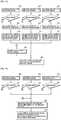
- FIG. 11is a schematic view illustrating types of alignment errors to be considered when a method for error compensation according to an exemplary embodiment of the present disclosure is performed.
- a sum of quantities of lights incident on from each light receiving unitwould have a predetermined value.
- all the light receiving units and the light source unitcome to touch the skin to allow a light, which is a subject of detection, to be incident on four light receiving units.
- a sum, in which all the quantities of lights incident on the light receiving units are addedmay have a predetermined value.
- quantity of light incident on the first to fourth light receiving unitsmay be respectively defined as a first light receiving signal (PD1), a second light receiving signal (PD2), a third light receiving signal (PD3), and a fourth light receiving signal (PD4).
- a difference(PD1+PD2-(PD3+PD4) between optical signals received by the light receiving units arranged on the upper surface and optical signals received by the light receiving units arranged on the bottom surface, a difference (PD1+PD3-(PD2+PD4)
Landscapes
- Health & Medical Sciences (AREA)
- Life Sciences & Earth Sciences (AREA)
- Engineering & Computer Science (AREA)
- Surgery (AREA)
- General Health & Medical Sciences (AREA)
- Biophysics (AREA)
- Pathology (AREA)
- Veterinary Medicine (AREA)
- Biomedical Technology (AREA)
- Heart & Thoracic Surgery (AREA)
- Medical Informatics (AREA)
- Molecular Biology (AREA)
- Public Health (AREA)
- Animal Behavior & Ethology (AREA)
- Physics & Mathematics (AREA)
- Cardiology (AREA)
- Physiology (AREA)
- Dentistry (AREA)
- Oral & Maxillofacial Surgery (AREA)
- Artificial Intelligence (AREA)
- Computer Vision & Pattern Recognition (AREA)
- Psychiatry (AREA)
- Signal Processing (AREA)
- Measuring Pulse, Heart Rate, Blood Pressure Or Blood Flow (AREA)
Description
- The present disclosure relates to an apparatus for measuring bio-information and a method for error compensation thereof.
- A conventional wearable activity tracker may be classified into two types. That is, a band type product made of elastic materials such as band type silicone or rubber, and a wristwatch type product. The former is wrist-unattachable and equipped only with a pedometer function mounted with an acceleration sensor, while the latter is equipped with an optical heart rate sensor to provide health information of a wearer such as heart rate activity state in addition to pedometer function.
- Meanwhile, the optical pulse sensor estimates heart rate activities by measuring blood flowing in the blood vessel using an optical characteristic of bio tissues. To be more specific, PPG (photoplethysmogram) observes optical characteristics of bio tissues such as light reflectivity, absorptance and transmittance that show during volumetric change in blood vessel by using a light, and measures the heart rate using the change. The method of non-invasive method is widely used due to enablement of measuring bio signals, advantageous because of miniaturized size and convenience in usage, and conducive to development of wearable life signal detection sensor.
- The optical heart rate sensor includes a light source and a light receiver, where when a light is incident on skin from the light source, and a light reflected from the incident light is collected by the light receiver, the number of heart rates can be detected from changes in quantity of the collected light.
US 2012/0306643 A1 describes a system that includes a wrist band having one or more sensors that measure the heart rate or other biometric data of a user wearing the band; and a display on the band that displays a message based on biometric data measured by the band. In one example, the band includes an accelerometer.WO 2010/007589 A1 describes a medical device having at least one sensor, such as a heart pulse sensor or a sensor for measuring acceleration. The medical device can be worn as a watch.EP 1297784 A1 describes a device for detecting the pulse rate. The measuring principle includes measuring the intensity of radiant energy after propagation of light through the human body tissue by means of four light detectors. A motion detecting device provides a motion reference signal. The input signals are processed in order to remove motion-related contributions due to motion of the detecting device on and with respect to the human body tissue.US 2004/0236227 A1 describes a portable instrument for measuring a physiological quantity, having an optical element forming a guide coupled to a light source for distributing light emission into several determined illumination zones. In an example, the same principle is applied to a detection device.KR 2013 0084993 A - However, the conventional optical heart rate sensor is disadvantageous in that only one PH (Photo diode) is available, a light source takes a shape of a point light source, and heart rate can be measured by being attached to skin. Thus, the conventional optical heart rate sensor is applicable only to a wrist watch type product, and is relatively difficult to be applied to a wrist-unattachable, band type product.
- The invention is indicated in the independent claims. Further embodiments are indicated in the dependent claims.
- Exemplary aspects of the present disclosure are to substantially solve at least the above problems and/or disadvantages and to provide at least the advantages as mentioned below. Thus, the present disclosure is directed to provide an apparatus for measuring bio-information and a method for error compensation therefor.
- In one general aspect of the present invention, there is provided an apparatus for measuring bio-information, the apparatus comprising:
- a heart rate sensor unit configured to measure heart rates by receiving a light that has entered and come out from skin;
- an acceleration sensor unit configured to output a step count by measuring the step count of a wearer;
- a display unit configured to display the measured heart rates and step count; and
- a wrist-wearable connection unit configured to electrically connect the heart rate sensor, the acceleration sensor unit and the display unit.
- The heart rate sensor unit includes,
a light source unit configured to emit a linear light source,
a light receiving unit configured to receive the light that has entered and come out from the skin from the light emitted from the light source, and
a controller configured to detect the heart rates from a quantity of light received by the light receiving unit. - Preferably, but not necessarily, the light source unit may include,
an LED (Light Emitting Diode) configured to emit a light of point light source,
a curved light guide of a particular curvature radius configured to advance the emitted light to a particular direction,
a plurality of V-shaped patterns configured to emit a light to a particular direction by refracting the emitted light, and
a reflective plate configured to reflect a light emitted to an outside from the light guide into an interior of the light guide. - Preferably, but not necessarily, the LED may use a yellowish green color light source.
- The light receiving unit includes,
a first light receiving unit arranged at an upper left surface based on a lengthwise direction of the light source,
a second light receiving unit arranged at an upper right surface based on a lengthwise direction of the light source,
a third light receiving unit arranged at a bottom left surface based on a lengthwise direction of the light source, and
a fourth light receiving unit arranged at a bottom right surface based on a lengthwise direction of the light source. - Preferably, but not necessarily, the light receiving unit may include,
a photodetector configured to receive a light that has entered and come out of skin from a light emitted from the light source unit, and
a light receiving house configured to wrap the photodetector and to gradually broaden at an entrance toward a skin contact surface. - Preferably, but not necessarily, the plurality of V-shaped patterns may taper off at a spacing of adjacent patterns as being distanced from the LED.
- Preferably, but not necessarily, the connection unit may be a wrist band type connector unit of elastic material.
- Preferably, but not necessarily, the connection unit may be a wrist watch type, wrist-attachable connector unit.
- In another general aspect of the present disclosure, there is provided a method for error compensation in a heart rate sensor including a first light receiving unit arranged at an upper left surface of a line light source, a second light receiving unit arranged at an upper right surface of the line light source,
- a third light receiving unit arranged at a bottom left surface of the line light source, and a fourth light receiving unit arranged at a bottom right surface of the line light source, the method comprising:
- detecting an error by comparing light signals received by the first to fourth light receiving units;
- multiplying a predetermined weight to a greater light signal as a result of comparison of the light signals when the error is generated; and
- adding a size of a light signal multiplied by the weight to a size of a light signal not multiplied by the weight.
- Preferably, but not necessarily, the error may include a first error, which is a difference between a first signal, which is a sum of light signals received by the first and second light receiving units and a second signal, which is a sum of light signals received by the third and fourth light receiving units,
a second error, which is a difference between a third signal, which is a sum of light signals received by the first and third light receiving units and a fourth signal, which is a sum of light signals received by the second and fourth light receiving units, and
a third error, which is a difference between a fifth signal, which is a sum of light signals received by the first and fourth light receiving units and a sixth signal, which is a sum of light signals received by the second and third light receiving units. - Preferably, but not necessarily, the step of multiplying a predetermined weight to a greater light signal as a result of comparison of the light signals when the error is generated may include,
multiplying a predetermined weight to a greater signal between the first and second signals when the first error is generated,
multiplying a predetermined weight to a greater signal between the third and fourth signals when the second error is generated, and
multiplying a predetermined weight to a greater signal between the fifth and sixth signals when the first error is generated. - Preferably, but not necessarily, the method may further comprise determining a greater value as a heart rate reference signal between a size of an optical signal multiplied by the weight and a size of an optical signal not multiplied by the weight.
- In still another general aspect of the present disclosure, there is provided a method for error compensation in a heart rate sensor including a first light receiving unit arranged at an upper left surface of a line light source, a second light receiving unit arranged at an upper right surface of the line light source,
a third light receiving unit arranged at a bottom left surface of the line light source, and a fourth light receiving unit arranged at a bottom right surface of the line light source, the method comprising: - detecting an error by comparing light signals received by the first to fourth light receiving units;
- multiplying a predetermined weight to a light signal having the greatest value as a result of comparison of the light signals when the error is generated; and
- adding a size of a light signal multiplied by the weight to a size of a light signal not multiplied by the weight.
- Preferably, but not necessarily, the step of detecting an error by comparing light signals received by the first to fourth light receiving units may include determining a light receiving unit having received a largest size of optical signal by comparing a first error, which is a difference between a first signal, which is a sum of light signals received by the first and second light receiving units and a second signal, which is a sum of light signals received by the third and fourth light receiving units, a second error, which is a difference between a third signal, which is a sum of light signals received by the first and third light receiving units and a fourth signal, which is a sum of light signals received by the second and fourth light receiving units, and a third error, which is a difference between a fifth signal, which is a sum of light signals received by the first and fourth light receiving units and a sixth signal, which is a sum of light signals received by the second and third light receiving units.
- The present disclosure has an advantageous effect in that heart rate can be accurately measured using a line light source instead of point light source, even if the apparatus for measuring the bio-information is not fully attached to a wrist.
- Another advantageous effect is that the light receiving efficiency can be greatly enhanced using four light receiving units.
- Still another advantageous effect is that the present invention can be applied to both the wrist band type connector unit and a wrist watch typed connector unit.
- Still further advantageous effect is that a heart rate signal can be stably detected even if a heart rate sensor including a plurality of light receiving units is not attached to skin.
- Still further advantageous effect is that the present invention can choose an appropriate method between a comparative signal weighting method and an absolute signal weighting method in consideration of weight setting, SNR (Signal-to-Noise-Ratio) and operation environment of heart rate sensor.
FIG.1 is a block diagram illustrating a configuration of an apparatus for measuring bio-information according to an exemplary embodiment of the present disclosure.FIG. 2 is a block diagram illustrating a configuration of a heart rate sensor unit according to an exemplary embodiment of the present disclosure.FIG. 3 is a schematic view illustrating arrangement of a light source unit of a heart rate sensor unit, and first to fourth light receiving units according to an exemplary embodiment of the present disclosure.FIG. 4 is a schematic view illustrating a structure of a light source unit according to an exemplary embodiment of the present disclosure.FIGS. 5 and 6 are respectively a perspective view and a bottom view of a structure of a light source unit according to an exemplary embodiment of the present disclosure.FIG. 7 is a plan view illustrating structures of light source unit of heart rate sensor unit, and first to fourth light receiving units according to an exemplary embodiment of the present disclosure.FIG. 8 is a lateral view illustrating structures of first to fourth light receiving units according to an exemplary embodiment of the present disclosure.FIG. 9 is a schematic view illustrating a heart rate sensor unit attached to skin of an apparatus for measuring bio-information according to an exemplary embodiment of the present disclosure.FIG. 10 is a schematic view illustrating a structure of an apparatus for measuring bio-information according to an exemplary embodiment of the present disclosure.FIG. 11 is a schematic view illustrating types of alignment errors to be considered when a method for error compensation according to an exemplary embodiment of the present disclosure is performed.FIG. 12 is a schematic view illustrating a method for error compensation according to an exemplary embodiment of the present disclosure.FIG. 13 is a schematic view illustrating a comparative signal weighting method in a method for error compensation according to an exemplary embodiment of the present disclosure.FIG. 14 is a schematic view illustrating an absolute signal weighting method in a method for error compensation according to an exemplary embodiment of the present disclosure.- Various exemplary embodiments will be described more fully hereinafter with reference to the accompanying drawings, in which some exemplary embodiments are shown. The present inventive concept may, however, be embodied in many different forms and should not be construed as limited to the example embodiments set forth herein. Rather, the described aspect is intended to embrace all such alterations, modifications, and variations that fall within the scope and novel idea of the present disclosure.
- Now, an exemplary embodiment of the present disclosure will be described in detail with reference to the accompanying drawings.
FIG.1 is a block diagram illustrating a configuration of an apparatus for measuring bio-information according to an exemplary embodiment of the present disclosure.- Referring to
FIG. 1 , an apparatus for measuring bio-information (hereinafter referred to as) may include a heart rate sensor unit (100), an acceleration sensor unit (200), a wrist-wearable connection unit (300) and a display unit (400). - The heart rate sensor unit (100) may include an optical heart rate sensor to display a heart rate (pulse) of a wearer on the display unit (400) by measuring the heart rate of the wearer. The heart rate sensor unit (100) uses a principle, in which a light that has entered and come out from the skin from the light emitted from a light source is changed by heart rate in time in terms of optical absorption degree in response to plastid in blood such as hemoglobin available in skin tissue and blood, where the heart rate sensor unit (100) receives a light returned by the light receiving unit of the heart rate sensor unit (100) and detects the heart rate by converting the received light to an electrical signal.
- The acceleration sensor unit (200) may measure an acceleration of an apparatus for measuring bio-information (apparatus) according to an exemplary embodiment of the present disclosure and provide a pedometer function. The acceleration sensor unit (200) may include an acceleration sensor mounted on a pedometer or a walk-step measuring device, measure an acceleration speed in response to movement of a wearer of the apparatus, and display on the display unit (400) a step count by converting the measured acceleration speed to the step count.
- The connection unit (300) functions to connect the heart rate sensor unit (100), the acceleration sensor unit (200) and the display unit (400), and may take a shape of being wearable on a wrist, a fore arm, an upper arm, a thigh, a head and/or a finger. The connection unit (300) may be formed in the shape of a band type connection unit of elastic material such as silicone and a rubber, may be formed in the shape of a wrist watch type connection unit wearable to be attached to a wrist like an wrist watch, or may be formed in the shape of a head band type connection unit wearable to be attached to a head like a head band.
- The display unit (400) may display heart rate information measured by the heart rate sensor unit (100). Furthermore, the display unit (400) may display pedometer information measured by the acceleration sensor unit (200).
FIG. 2 is a block diagram illustrating a configuration of a heart rate sensor unit (100) according to an exemplary embodiment of the present disclosure.- Referring to
FIG. 2 , the heart rate sensor unit (100) according to an exemplary embodiment of the present disclosure may include a light source unit (110), first to fourth light receiving units (120, 130, 140, 150) and a controller (160). - The light source unit (110) emits a light. The light source unit (110) may use an optical light guide for emitting a line light source. The use of line light source may irradiate a light on a broader skin area than that of point light source, whereby a sufficient quantity of light can be incident on a wrist area even if the apparatus is not closely attached to the wrist. A detailed structure of the light source unit (110) will be described with reference to
FIGS. 3 to 6 later. - The first to fourth light receiving units (120, 130, 140, 150) may be symmetrically (vertically and horizontally) arranged based on lengthwise direction of the light source unit (110), and may receive a light emitted from the light source unit (110) that has entered and come out from the skin. The arrangement of the first to fourth light receiving units (120, 130, 140, 150) may be changed depending on a length and an area of the light source unit (110).
- The first to fourth light receiving units (120, 130, 140, 150) may include first to fourth photodetectors (121, 131, 141, 151), and the first to fourth photodetectors (121, 131, 141, 151) may be PDs (Photo Diodes). The first to fourth light receiving units (120, 130, 140, 150) may transmit the received light to the controller (160) by converting the received light to an electrical signal.
- The controller (160) may detect quantity of light emitted from the light source unit (110) and may receive the light received by the first to fourth light receiving units (120, 130, 140, 150) in electrical signal.
FIG. 3 is a schematic view illustrating arrangement of the light source unit (110) of the heart rate sensor unit (100), and the first to fourth light receiving units(120, 130, 140, 150) according to an exemplary embodiment of the present disclosure.- Referring to
FIG. 3 , the light source unit (110) may be a line light source unit configured to take a shape of a curved surface. When a curved line light source is employed, the light source unit can be attached to a measurement unit having a curve as in the wrist. The first light receiving unit (120) may be arranged at an upper left surface based on a lengthwise direction of the light source, the second light receiving unit (130) may be arranged at an upper right surface based on a lengthwise direction of the light source, the third light receiving unit (140) may be arranged at a bottom left surface based on a lengthwise direction of the light source, and the fourth light receiving unit (150) may be arranged at a bottom right surface based on a lengthwise direction of the light source. FIG. 4 is a schematic view illustrating a structure of the light source unit (110) according to an exemplary embodiment of the present disclosure.- Referring to
FIG. 4 , although the light source unit (110) may be preferably a line light source unit configured to take a shape of a curved surface, the light source unit is illustrated herein as a line light source unit having no curvature, for convenience sake. - The light source unit may include an LED (Light Emitting Diode, 111), a curved light guide (112), a plurality of V-shaped patterns (113) and a reflective plate (114).
- The LED (111) may emit a light of point light source shape to a lengthwise direction of the light source unit (110). Although only one LED (111) is illustrated at a distal end in
FIG. 4D , a total of two LEDs may be arranged each at a distal end. - Although the LED (111) uses a wavelength of red or an infrared region, the LED (111) preferably uses a yellowish green color light source in consideration of optical characteristic of skin tissue. The curved light guide (112) is preferred to have a particular curvature radius of about 20mm to allow being attached to a radial artery of the wrist when the heart rate sensor unit (100) is brought into contact with the wrist. The curved light guide (112) may be formed with a flexible material.
- The plurality of V-shaped patterns (113) may taper off at a spacing of adjacent patterns as being distanced from the LED (111), which is to emit as much as uniform refracted light because the quantity of reached light decreases as being distanced from the light source.
- The reflective plate (114) may be arranged on all surfaces except for a direction from which the light is emitted from the curved light guide (112) to reflect the light into an interior of the light guide, whereby the light loss can be minimized.
FIGS. 5 and 6 are respectively a perspective view and a bottom view of a structure of a light source unit according to an exemplary embodiment of the present disclosure.- Referring to
FIGS. 5 and 6 , although the light source unit (110) may be preferably a line light source unit configured to take a shape of a curved surface, the light source unit is illustrated herein as a line light source unit having no curvature, for convenience sake. - The plurality of V-shaped patterns (113) may taper off at a spacing of adjacent patterns as being distanced from the LED (111), which is to emit as much uniform refracted light as possible, because the quantity of reached light decreases as being distanced from the light source.
- The curved light guide (112) is formed with a plurality of V-shaped patterns (113) to minimize the quantity of leaked light by arranging the reflective plate (114) on all surfaces except for a direction from which the light is emitted.
FIG. 7 is a plan view illustrating structures of light source unit (110) of heart rate sensor unit (100), and first to fourth light receiving units (120, 130, 140, 150) according to an exemplary embodiment of the present disclosure.- Referring to
FIG. 7 , the first to fourth light receiving units (120, 130, 140, 150) may be symmetrically (vertically and horizontally) arranged based on lengthwise direction of the light source unit (110). - Each of the first to fourth light receiving units (120, 130, 140, 150) may take a combined shape of first to fourth photodetectors (121, 131, 141, 151) and a light receiving housing (170). The first to fourth photodetectors (121, 131, 141, 151) may be PDs (Photo Diodes) configured to receive light emitted from the light source unit that has entered and come out of the skin.
- The light receiving housing (170) may be surface-treated with a hollow material of high reflectivity to take a shape of wrapping the first to fourth photodetectors (121, 131, 141, 151). When the PD is directly arranged on the surface of skin using no light receiving housing, the light receiving rate of light that has entered and come out of the skin may decrease, such that the light receiving housing (170) may be employed to collect as much light as possible.
- The PD may be positioned at an area inside the light receiving housing distanced at a predetermined space from the skin. The light receiving housing (170) may take a shape of a bottomless quadrangular pyramid.
FIG. 8 is a lateral view illustrating structures of first to fourth light receiving units (120, 130, 140, 150) according to an exemplary embodiment of the present disclosure.- Referring to
FIG.8 , the first to fourth light receiving units (120, 130, 140, 150) may include the first to fourth photodetectors (121, 131, 141, 151) and the light receiving housing (170). - The light receiving housing (170) may have a hollow inside to prevent from being directly contact to the skin and take a shape of wrapping the first to fourth photodetectors (121, 131, 141, 151) to collect the light that has entered and come out from the skin.
- Referring to
FIG.8 , the light receiving housing (170) may take a shape of a hollow and bottomless quadrangular pyramid to include the first to fourth photodetectors (121, 131, 141, 151), the present disclosure is not limited thereto, and the light receiving housing (170) may take a shape of any configuration capable of collecting light and being attached to the skin, such as a circular truncated cone, a cube and/or a rectangular parallelepiped, each being less a bottom surface. FIG. 9 is a schematic view illustrating a heart rate sensor unit (100) attached to skin of an apparatus for measuring bio-information according to an exemplary embodiment of the present disclosure.- Referring to
FIG. 9 , the light source unit (110) of the heart rate sensor unit (100) may include an LED (111) and a curved light guide (112). - The light source unit (110) may be centrally formed with the curved light guide (112) having a predetermined radius of curvature to be attached to a wrist area, and may symmetrically (vertically and horizontally) include the first to fourth light receiving units (120, 130, 140, 150) based on a lengthwise direction of the light source unit (110) to allow the LED to come thereon. Each of the first to fourth light receiving units (120, 130, 140, 150) may include the first to fourth photodetectors (121, 131, 141, 151), and a light receiving housing (170) of a bottomless quadrangular pyramid shape.
- It is preferable that the heart rate sensor unit (100) be completely attached the skin, but if the heart rate sensor unit (100) is completely attached to the skin, the wearer may feel uncomfortable, such that the connection unit (300) may be in a band type connection unit of elastic material such as silicone and a rubber. Although the band type connection unit may be formed with a space between the band and the attached area with the skin, the heart rate sensor unit (100) according to the present disclosure can emit a sufficient quantity of light using a line light source and four light receiving units to allow measuring an accurate heart rate count.
FIG. 10 is a schematic view illustrating a structure of an apparatus for measuring bio-information according to an exemplary embodiment of the present disclosure.- Referring to
FIG. 10 , the apparatus for measuring bio-information according to an exemplary embodiment of the present disclosure may include a heart rate sensor unit (100), a connection unit (300) and a display unit (400). As illustrated inFIG.1 , an acceleration sensor unit (200) may be additionally formed in the apparatus, and other bio-information measuring modules may be further added thereto. - Furthermore, the connection unit (300) may be designed to replace various modules used in the apparatus. Although the connection unit (300) in
FIG. 10 is illustrated in the form of a band type connection unit, the present disclosure is not limited thereto, and may be formed in the shape of a wrist watch type connection unit wearable to be attached to a wrist like an wrist watch, and any type wearable to the wrist is also acceptable. The display unit (400) may display various bio-information in addition to a heart rate signal measured by the heart rate sensor unit (100). For example, when a temperature sensor module (not shown) is worn by a wearer, a body temperature may be measured and displayed on the display unit (400). FIG. 11 is a schematic view illustrating types of alignment errors to be considered when a method for error compensation according to an exemplary embodiment of the present disclosure is performed.- In ideal case, that is, when the heart rate sensor unit is completely attached to the skin, a sum of quantities of lights incident on from each light receiving unit would have a predetermined value. To be more specific, when the heart rate sensor unit is completely attached to the skin, all the light receiving units and the light source unit come to touch the skin to allow a light, which is a subject of detection, to be incident on four light receiving units. Thus, a sum, in which all the quantities of lights incident on the light receiving units are added, may have a predetermined value.
- However, when the heart rate sensor unit is not completely attached to the skin to allow some of the light receiving units to be attached to the skin and to allow some of the light receiving units not to be attached to the skin, there may be generated an alignment error. Referring to
FIG. 11 , quantity of light incident on the first to fourth light receiving units (120, 130, 140, 150) may be respectively defined as a first light receiving signal (PD1), a second light receiving signal (PD2), a third light receiving signal (PD3), and a fourth light receiving signal (PD4). - According to the method for error compensation according to an exemplary embodiment of the present disclosure, when check is made on a sum (PD1+PD2+PD3+PD4) of quantities of lights incident on each light receiving units, a difference (PD1+PD2-(PD3+PD4) between optical signals received by the light receiving units arranged on the upper surface and optical signals received by the light receiving units arranged on the bottom surface, a difference (PD1+PD3-(PD2+PD4)
Claims (13)
- An apparatus for measuring bio-information, the apparatus comprising:a heart rate sensor unit (100) configured to measure heart rates by receiving a light that has entered and come out from skin;an acceleration sensor unit (200) configured to output a step count by measuring the step count of a wearer;a display unit (400) configured to display the measured heart rates and step count; anda wrist-wearable connection unit (300) configured to electrically connect the heart rate sensor, the acceleration sensor unit and the display unit,characterized in that the heart rate sensor unit (100) includes a line light source unit (110), a light receiving unit (120,130,140,150) configured to receive the light that has entered and come out from the skin from the light emitted from the light source unit, and a controller (160) configured to detect the heart rates from a quantity of light received by the light receiving unit,wherein the light receiving unit (120,130,140,150) includes a first light receiving unit (120) arranged at an upper left surface based on a lengthwise direction of the light source unit, a second light receiving unit (130) arranged at an upper right surface based on a lengthwise direction of the light source unit, a third light receiving unit (140) arranged at a bottom left surface based on a lengthwise direction of the light source unit, and a fourth light receiving unit (150) arranged at a bottom right surface based on a lengthwise direction of the light source unit,furthercharacterized in that the heart rate sensor unit (100) is configured to detect an error by comparing light signals received by the first to fourth light receiving units (120,130,140,150), multiply a predetermined weight to a greater light signal as a result of comparison of the light signals when the error is generated, and add a size of a light signal multiplied by the weight to a size of a light signal not multiplied by the weight.
- The apparatus of claim 1, wherein the light source unit (110) includes,
an LED (Light Emitting Diode;111) configured to emit a light of point light source shape,
a curved light guide (112) of a particular curvature radius configured to advance the emitted light to a particular direction,
a plurality of V-shaped patterns (113) configured to emit a light to a particular direction by refracting the emitted light, and
a reflective plate (114) configured to reflect a light emitted to an outside from the light guide into an interior of the light guide. - The apparatus of claim 2, wherein the LED (111) uses a yellowish green color light source.
- The apparatus of claim 1, wherein the light receiving unit includes,
a photodetector (121, 131, 141, 151) configured to receive a light that has entered and come out of skin from a light emitted from the light source unit, and
a light receiving housing (170) configured to wrap the photodetector and to gradually broaden at an entrance toward a skin contact surface. - The apparatus of claim 2, wherein the plurality of V-shaped patterns (113) tapers off at a spacing of adjacent patterns as being distanced from the LED.
- The apparatus of claim 1, wherein the connection unit (300) is a wrist band type connector unit of elastic material.
- The apparatus of claim 1, wherein the connection unit (300) is a wrist watch type, wrist-attachable connector unit.
- A method for error compensation in a heart rate sensor (100) including a first light receiving unit (120) arranged at an upper left surface of a line light source, a second light receiving unit (130) arranged at an upper right surface of the line light source,
a third light receiving unit (140) arranged at a bottom left surface of the line light source, and a fourth light receiving unit (150) arranged at a bottom right surface of the line light source, the method comprising:detecting an error by comparing light signals received by the first to fourth light receiving units (120,130,140,150);multiplying a predetermined weight to a greater light signal as a result of comparison of the light signals when the error is generated; andadding a size of a light signal multiplied by the weight to a size of a light signal not multiplied by the weight. - The method of claim 8, wherein the error includes a first error, which is a difference between a first signal, which is a sum of light signals received by the first light receiving unit (120) and the second light receiving unit (130) and a second signal, which is a sum of light signals received by the third light receiving unit (140) and the fourth light receiving unit (150),
a second error, which is a difference between a third signal, which is a sum of light signals received by the first light receiving unit (120) and the third light receiving unit (140) and a fourth signal, which is a sum of light signals received by the second light receiving unit (130) and the fourth light receiving unit (150), and
a third error, which is a difference between a fifth signal, which is a sum of light signals received by the first light receiving unit (120) and the fourth light receiving unit (150) and a sixth signal, which is a sum of light signals received by the second light receiving unit (130) and the third light receiving unit (140). - The method of claim 9, wherein the step of multiplying a predetermined weight to a greater light signal as a result of comparison of the light signals when the error is generated includes,
multiplying a predetermined weight to a greater signal between the first and second signals when the first error is generated,
multiplying a predetermined weight to a greater signal between the third and fourth signals when the second error is generated, and
multiplying a predetermined weight to a greater signal between the fifth and sixth signals when the first error is generated. - The method of claim 10, wherein the method further comprises
determining a greater value as a heart rate reference signal between a size of an optical signal multiplied by the weight and a size of an optical signal not multiplied by the weight. - A method for error compensation in a heart rate sensor including a first light receiving unit (120) arranged at an upper left surface of a line light source, a second light receiving unit (130) arranged at an upper right surface of the line light source,
a third light receiving unit (140) arranged at a bottom left surface of the line light source, and a fourth light receiving unit (150) arranged at a bottom right surface of the line light source, the method comprising:detecting an error by comparing light signals received by the first to fourth light receiving units (120,130,140,150);multiplying a predetermined weight to a light signal having the greatest value as a result of comparison of the light signals when the error is generated; andadding a size of a light signal multiplied by the weight to a size of a light signal not multiplied by the weight. - The method of claim 12, wherein the step of detecting an error by comparing light signals received by the first to fourth light receiving units includes
determining a light receiving unit having received a largest size of optical signal by comparing
a first error, which is a difference between a first signal, which is a sum of light signals received by the first light receiving unit (120) and the second light receiving unit (130) and a second signal, which is a sum of light signals received by the third light receiving unit (140) and the fourth light receiving unit (150),
a second error, which is a difference between a third signal, which is a sum of light signals received by the first light receiving unit (120) and the third light receiving unit (140) and a fourth signal, which is a sum of light signals received by the second light receiving unit (130) and the fourth light receiving unit (150), and
a third error, which is a difference between a fifth signal, which is a sum of light signals received by the first light receiving unit (120) and the fourth light receiving unit (150) and a sixth signal, which is a sum of light signals received by the second light receiving unit (130) and third light receiving unit (140).
Applications Claiming Priority (3)
| Application Number | Priority Date | Filing Date | Title |
|---|---|---|---|
| KR1020130158169AKR102223689B1 (en) | 2013-12-18 | 2013-12-18 | Apparatus for measuring bio-information |
| KR1020130162325AKR102136317B1 (en) | 2013-12-24 | 2013-12-24 | A method for error compensation |
| PCT/KR2014/007864WO2015093716A1 (en) | 2013-12-18 | 2014-08-25 | Apparatus for measuring bio-information and a method for error compensation thereof |
Publications (3)
| Publication Number | Publication Date |
|---|---|
| EP3082584A1 EP3082584A1 (en) | 2016-10-26 |
| EP3082584A4 EP3082584A4 (en) | 2017-08-09 |
| EP3082584B1true EP3082584B1 (en) | 2020-10-21 |
Family
ID=53366981
Family Applications (1)
| Application Number | Title | Priority Date | Filing Date |
|---|---|---|---|
| EP14870684.9AActiveEP3082584B1 (en) | 2013-12-18 | 2014-08-25 | Apparatus for measuring bio-information and a method for error compensation thereof |
Country Status (4)
| Country | Link |
|---|---|
| US (1) | US20150164352A1 (en) |
| EP (1) | EP3082584B1 (en) |
| CN (1) | CN105828708B (en) |
| WO (1) | WO2015093716A1 (en) |
Families Citing this family (20)
| Publication number | Priority date | Publication date | Assignee | Title |
|---|---|---|---|---|
| US20160235369A1 (en)* | 2013-09-27 | 2016-08-18 | Pioneer Corporation | Measuring instrument |
| US10327649B1 (en) | 2014-03-31 | 2019-06-25 | Sensogram Technologies, Inc. | Non-invasive wearable blood pressure monitoring system |
| US10117586B1 (en) | 2014-03-31 | 2018-11-06 | Sensogram Technologies, Inc. | Continuous non-invasive wearable blood pressure monitoring system |
| US9603569B2 (en)* | 2014-07-11 | 2017-03-28 | Verily Life Sciences Llc | Positioning a wearable device for data collection |
| CN106999073A (en)* | 2014-12-16 | 2017-08-01 | 皇家飞利浦有限公司 | Optics vital sign sensors |
| CN105078414A (en)* | 2015-08-21 | 2015-11-25 | 京东方科技集团股份有限公司 | Human sleep monitoring device and method |
| US10667705B2 (en)* | 2015-09-23 | 2020-06-02 | Qualcomm Incorporated | System and method for obtaining blood pressure measurement |
| US10667706B2 (en)* | 2015-09-23 | 2020-06-02 | Qualcomm Incorporated | System and method for obtaining blood pressure measurement |
| CN106371816B (en)* | 2015-10-21 | 2020-11-27 | 北京智谷睿拓技术服务有限公司 | Left-right hand determination method and device |
| US10117598B1 (en) | 2015-11-08 | 2018-11-06 | Sensogram Technologies, Inc. | Non-invasive wearable respiration rate monitoring system |
| US10085652B2 (en)* | 2016-03-18 | 2018-10-02 | Qualcomm Incorporated | Optical measuring device for cardiovascular diagnostics |
| CN106377243A (en)* | 2016-10-12 | 2017-02-08 | 广东小天才科技有限公司 | Heart rate detection method and device |
| WO2018152186A1 (en)* | 2017-02-17 | 2018-08-23 | Sensogram Technologies, Inc | Integrated biosensor |
| US20180353090A1 (en)* | 2017-06-13 | 2018-12-13 | Huami Inc. | Adaptive Heart Rate Estimation |
| US12066702B1 (en) | 2018-09-25 | 2024-08-20 | Apple Inc. | Systems and methods for distinguishing between a user and an object |
| KR102773553B1 (en)* | 2019-02-01 | 2025-02-25 | 삼성전자주식회사 | Heartbeat index determination apparatus and method |
| US11857298B1 (en) | 2019-09-06 | 2024-01-02 | Apple Inc. | Devices having matter differentiation detectors |
| US12089931B1 (en) | 2020-09-11 | 2024-09-17 | Apple Inc. | Optical sensor for skin-contact detection and physiological parameter measurement at wearable electronic device |
| US12204289B1 (en) | 2020-09-11 | 2025-01-21 | Apple Inc. | Device removal indication using different object proximity thresholds |
| US12164027B1 (en) | 2020-09-14 | 2024-12-10 | Apple Inc. | Multi-pathway distance measurements for optical sensors |
Family Cites Families (22)
| Publication number | Priority date | Publication date | Assignee | Title |
|---|---|---|---|---|
| JP4286328B2 (en)* | 1998-02-25 | 2009-06-24 | コーニンクレッカ フィリップス エレクトロニクス エヌ ヴィ | Method and system for measuring performance during exercise and athletic shoes for use in the system |
| EP1163878A1 (en)* | 2000-06-15 | 2001-12-19 | The Procter & Gamble Company | Device for body activity detection and processing |
| GB0017051D0 (en)* | 2000-07-11 | 2000-08-30 | Danish Dermatological Dev A S | Improved light guide for coupling light output from a light source to the skin |
| JP2002320591A (en)* | 2001-04-25 | 2002-11-05 | Sharp Corp | Biological signal measurement device |
| JP2002360530A (en)* | 2001-06-11 | 2002-12-17 | Waatekkusu:Kk | Pulse wave sensor and pulse rate detector |
| EP1297784B8 (en)* | 2001-09-28 | 2011-01-12 | CSEM Centre Suisse d'Electronique et de Microtechnique SA - Recherche et Développement | Method and device for pulse rate detection |
| CH696516A5 (en)* | 2003-05-21 | 2007-07-31 | Asulab Sa | Portable instrument for measuring a physiological quantity comprising a device for illuminating the surface of an organic tissue. |
| AU2004290588A1 (en)* | 2003-11-18 | 2005-06-02 | Vivometrics, Inc. | Method and system for processing data from ambulatory physiological monitoring |
| US7729748B2 (en)* | 2004-02-17 | 2010-06-01 | Joseph Florian | Optical in-vivo monitoring systems |
| US7468036B1 (en)* | 2004-09-28 | 2008-12-23 | Impact Sports Technology, Inc. | Monitoring device, method and system |
| US8618930B2 (en)* | 2005-03-11 | 2013-12-31 | Aframe Digital, Inc. | Mobile wireless customizable health and condition monitor |
| EP1965697A2 (en)* | 2005-12-19 | 2008-09-10 | Koninklijke Philips Electronics N.V. | Apparatus for monitoring a person's heart rate and/or heart rate variation; wristwatch comprising the same |
| KR100770833B1 (en)* | 2006-03-09 | 2007-10-26 | 삼성전자주식회사 | Optical sensor module |
| WO2010007589A1 (en)* | 2008-07-18 | 2010-01-21 | Koninklijke Philips Electronics N.V. | Medical device and method for monitoring status information |
| US8788002B2 (en)* | 2009-02-25 | 2014-07-22 | Valencell, Inc. | Light-guiding devices and monitoring devices incorporating same |
| US8105208B2 (en)* | 2009-05-18 | 2012-01-31 | Adidas Ag | Portable fitness monitoring systems with displays and applications thereof |
| JP5471736B2 (en)* | 2010-04-06 | 2014-04-16 | セイコーエプソン株式会社 | Pulse wave measuring device and pulse wave measuring method |
| US9011292B2 (en)* | 2010-11-01 | 2015-04-21 | Nike, Inc. | Wearable device assembly having athletic functionality |
| US20120271121A1 (en)* | 2010-12-29 | 2012-10-25 | Basis Science, Inc. | Integrated Biometric Sensing and Display Device |
| US8947226B2 (en)* | 2011-06-03 | 2015-02-03 | Brian M. Dugan | Bands for measuring biometric information |
| US20120316455A1 (en)* | 2011-06-10 | 2012-12-13 | Aliphcom | Wearable device and platform for sensory input |
| US20130144136A1 (en)* | 2011-12-01 | 2013-06-06 | Russell Rymut | Method and apparatus for determining tissue hydration |
- 2014
- 2014-08-22USUS14/466,693patent/US20150164352A1/ennot_activeAbandoned
- 2014-08-25EPEP14870684.9Apatent/EP3082584B1/enactiveActive
- 2014-08-25CNCN201480069154.4Apatent/CN105828708B/enactiveActive
- 2014-08-25WOPCT/KR2014/007864patent/WO2015093716A1/enactiveApplication Filing
Non-Patent Citations (1)
| Title |
|---|
| None* |
Also Published As
| Publication number | Publication date |
|---|---|
| US20150164352A1 (en) | 2015-06-18 |
| WO2015093716A1 (en) | 2015-06-25 |
| CN105828708A (en) | 2016-08-03 |
| EP3082584A1 (en) | 2016-10-26 |
| CN105828708B (en) | 2019-12-03 |
| EP3082584A4 (en) | 2017-08-09 |
Similar Documents
| Publication | Publication Date | Title |
|---|---|---|
| EP3082584B1 (en) | Apparatus for measuring bio-information and a method for error compensation thereof | |
| US10172529B2 (en) | Systems and methods for detecting physiological information of a user | |
| US11330993B2 (en) | Sensor and method for continuous health monitoring | |
| US20180235483A1 (en) | Integrated biosensor | |
| US10357165B2 (en) | Method and apparatus for acquiring bioinformation and apparatus for testing bioinformation | |
| US10251565B2 (en) | Multi-channel vitals device | |
| US10299724B2 (en) | Wristwatch including an integrated pulse oximeter or other modules that sense physiological data | |
| JP3722203B2 (en) | Pulse wave sensor | |
| US10219709B2 (en) | Sensor and method for continuous health monitoring | |
| JP2002360530A (en) | Pulse wave sensor and pulse rate detector | |
| US20230079736A1 (en) | Wearing detection techniques for wearable devices | |
| KR20100091592A (en) | Pulse wave measuring apparatus capable of wearing on a wrist | |
| US20180092602A1 (en) | Synthetic Aperture Photoplethysmography Sensor | |
| US11744519B2 (en) | Biological information measurement device | |
| CN107106036B (en) | System and method for optical isolation in measuring physiological parameters | |
| US20180235489A1 (en) | Photoplethysmographic wearable blood pressure monitoring system and methods | |
| KR20150068279A (en) | Self-aligning sensor array and method for self-aligning the same | |
| EP2928371B1 (en) | Method for spectrophotometrically determining a blood oxygen parameter | |
| CN110584627A (en) | Head-mounted physiological parameter monitoring device and exercise reminding method based on target heart rate | |
| JP2019513035A (en) | Optical measurement device for cardiovascular diagnosis | |
| CN102688043B (en) | Oximeter | |
| CN104367310A (en) | Wearable heart rate detection device | |
| US20220007954A1 (en) | Optical light guide for optical sensor | |
| KR102223689B1 (en) | Apparatus for measuring bio-information | |
| JP2013000540A (en) | Pulse wave detector, and pulse wave detection system |
Legal Events
| Date | Code | Title | Description |
|---|---|---|---|
| PUAI | Public reference made under article 153(3) epc to a published international application that has entered the european phase | Free format text:ORIGINAL CODE: 0009012 | |
| 17P | Request for examination filed | Effective date:20160531 | |
| AK | Designated contracting states | Kind code of ref document:A1 Designated state(s):AL AT BE BG CH CY CZ DE DK EE ES FI FR GB GR HR HU IE IS IT LI LT LU LV MC MK MT NL NO PL PT RO RS SE SI SK SM TR | |
| AX | Request for extension of the european patent | Extension state:BA ME | |
| DAX | Request for extension of the european patent (deleted) | ||
| A4 | Supplementary search report drawn up and despatched | Effective date:20170706 | |
| RIC1 | Information provided on ipc code assigned before grant | Ipc:A61B 5/0205 20060101ALI20170630BHEP Ipc:A61B 5/024 20060101ALI20170630BHEP Ipc:A61B 5/11 20060101ALI20170630BHEP Ipc:A61B 5/02 20060101AFI20170630BHEP | |
| GRAP | Despatch of communication of intention to grant a patent | Free format text:ORIGINAL CODE: EPIDOSNIGR1 | |
| STAA | Information on the status of an ep patent application or granted ep patent | Free format text:STATUS: GRANT OF PATENT IS INTENDED | |
| INTG | Intention to grant announced | Effective date:20200519 | |
| RIN1 | Information on inventor provided before grant (corrected) | Inventor name:YOON, HYOUNG KIL Inventor name:JIN, WON HYEOG Inventor name:JO, IN AH | |
| GRAS | Grant fee paid | Free format text:ORIGINAL CODE: EPIDOSNIGR3 | |
| GRAA | (expected) grant | Free format text:ORIGINAL CODE: 0009210 | |
| STAA | Information on the status of an ep patent application or granted ep patent | Free format text:STATUS: THE PATENT HAS BEEN GRANTED | |
| AK | Designated contracting states | Kind code of ref document:B1 Designated state(s):AL AT BE BG CH CY CZ DE DK EE ES FI FR GB GR HR HU IE IS IT LI LT LU LV MC MK MT NL NO PL PT RO RS SE SI SK SM TR | |
| REG | Reference to a national code | Ref country code:GB Ref legal event code:FG4D | |
| REG | Reference to a national code | Ref country code:CH Ref legal event code:EP | |
| REG | Reference to a national code | Ref country code:IE Ref legal event code:FG4D | |
| REG | Reference to a national code | Ref country code:DE Ref legal event code:R096 Ref document number:602014071555 Country of ref document:DE | |
| REG | Reference to a national code | Ref country code:AT Ref legal event code:REF Ref document number:1324975 Country of ref document:AT Kind code of ref document:T Effective date:20201115 | |
| REG | Reference to a national code | Ref country code:AT Ref legal event code:MK05 Ref document number:1324975 Country of ref document:AT Kind code of ref document:T Effective date:20201021 | |
| REG | Reference to a national code | Ref country code:NL Ref legal event code:MP Effective date:20201021 | |
| PG25 | Lapsed in a contracting state [announced via postgrant information from national office to epo] | Ref country code:FI Free format text:LAPSE BECAUSE OF FAILURE TO SUBMIT A TRANSLATION OF THE DESCRIPTION OR TO PAY THE FEE WITHIN THE PRESCRIBED TIME-LIMIT Effective date:20201021 Ref country code:RS Free format text:LAPSE BECAUSE OF FAILURE TO SUBMIT A TRANSLATION OF THE DESCRIPTION OR TO PAY THE FEE WITHIN THE PRESCRIBED TIME-LIMIT Effective date:20201021 Ref country code:PT Free format text:LAPSE BECAUSE OF FAILURE TO SUBMIT A TRANSLATION OF THE DESCRIPTION OR TO PAY THE FEE WITHIN THE PRESCRIBED TIME-LIMIT Effective date:20210222 Ref country code:NO Free format text:LAPSE BECAUSE OF FAILURE TO SUBMIT A TRANSLATION OF THE DESCRIPTION OR TO PAY THE FEE WITHIN THE PRESCRIBED TIME-LIMIT Effective date:20210121 Ref country code:NL Free format text:LAPSE BECAUSE OF FAILURE TO SUBMIT A TRANSLATION OF THE DESCRIPTION OR TO PAY THE FEE WITHIN THE PRESCRIBED TIME-LIMIT Effective date:20201021 Ref country code:GR Free format text:LAPSE BECAUSE OF FAILURE TO SUBMIT A TRANSLATION OF THE DESCRIPTION OR TO PAY THE FEE WITHIN THE PRESCRIBED TIME-LIMIT Effective date:20210122 | |
| REG | Reference to a national code | Ref country code:LT Ref legal event code:MG4D | |
| PG25 | Lapsed in a contracting state [announced via postgrant information from national office to epo] | Ref country code:PL Free format text:LAPSE BECAUSE OF FAILURE TO SUBMIT A TRANSLATION OF THE DESCRIPTION OR TO PAY THE FEE WITHIN THE PRESCRIBED TIME-LIMIT Effective date:20201021 Ref country code:IS Free format text:LAPSE BECAUSE OF FAILURE TO SUBMIT A TRANSLATION OF THE DESCRIPTION OR TO PAY THE FEE WITHIN THE PRESCRIBED TIME-LIMIT Effective date:20210221 Ref country code:LV Free format text:LAPSE BECAUSE OF FAILURE TO SUBMIT A TRANSLATION OF THE DESCRIPTION OR TO PAY THE FEE WITHIN THE PRESCRIBED TIME-LIMIT Effective date:20201021 Ref country code:SE Free format text:LAPSE BECAUSE OF FAILURE TO SUBMIT A TRANSLATION OF THE DESCRIPTION OR TO PAY THE FEE WITHIN THE PRESCRIBED TIME-LIMIT Effective date:20201021 Ref country code:BG Free format text:LAPSE BECAUSE OF FAILURE TO SUBMIT A TRANSLATION OF THE DESCRIPTION OR TO PAY THE FEE WITHIN THE PRESCRIBED TIME-LIMIT Effective date:20210121 Ref country code:AT Free format text:LAPSE BECAUSE OF FAILURE TO SUBMIT A TRANSLATION OF THE DESCRIPTION OR TO PAY THE FEE WITHIN THE PRESCRIBED TIME-LIMIT Effective date:20201021 Ref country code:ES Free format text:LAPSE BECAUSE OF FAILURE TO SUBMIT A TRANSLATION OF THE DESCRIPTION OR TO PAY THE FEE WITHIN THE PRESCRIBED TIME-LIMIT Effective date:20201021 | |
| PG25 | Lapsed in a contracting state [announced via postgrant information from national office to epo] | Ref country code:HR Free format text:LAPSE BECAUSE OF FAILURE TO SUBMIT A TRANSLATION OF THE DESCRIPTION OR TO PAY THE FEE WITHIN THE PRESCRIBED TIME-LIMIT Effective date:20201021 | |
| REG | Reference to a national code | Ref country code:DE Ref legal event code:R097 Ref document number:602014071555 Country of ref document:DE | |
| PG25 | Lapsed in a contracting state [announced via postgrant information from national office to epo] | Ref country code:RO Free format text:LAPSE BECAUSE OF FAILURE TO SUBMIT A TRANSLATION OF THE DESCRIPTION OR TO PAY THE FEE WITHIN THE PRESCRIBED TIME-LIMIT Effective date:20201021 Ref country code:SK Free format text:LAPSE BECAUSE OF FAILURE TO SUBMIT A TRANSLATION OF THE DESCRIPTION OR TO PAY THE FEE WITHIN THE PRESCRIBED TIME-LIMIT Effective date:20201021 Ref country code:LT Free format text:LAPSE BECAUSE OF FAILURE TO SUBMIT A TRANSLATION OF THE DESCRIPTION OR TO PAY THE FEE WITHIN THE PRESCRIBED TIME-LIMIT Effective date:20201021 Ref country code:SM Free format text:LAPSE BECAUSE OF FAILURE TO SUBMIT A TRANSLATION OF THE DESCRIPTION OR TO PAY THE FEE WITHIN THE PRESCRIBED TIME-LIMIT Effective date:20201021 Ref country code:CZ Free format text:LAPSE BECAUSE OF FAILURE TO SUBMIT A TRANSLATION OF THE DESCRIPTION OR TO PAY THE FEE WITHIN THE PRESCRIBED TIME-LIMIT Effective date:20201021 Ref country code:EE Free format text:LAPSE BECAUSE OF FAILURE TO SUBMIT A TRANSLATION OF THE DESCRIPTION OR TO PAY THE FEE WITHIN THE PRESCRIBED TIME-LIMIT Effective date:20201021 | |
| PLBE | No opposition filed within time limit | Free format text:ORIGINAL CODE: 0009261 | |
| STAA | Information on the status of an ep patent application or granted ep patent | Free format text:STATUS: NO OPPOSITION FILED WITHIN TIME LIMIT | |
| PG25 | Lapsed in a contracting state [announced via postgrant information from national office to epo] | Ref country code:DK Free format text:LAPSE BECAUSE OF FAILURE TO SUBMIT A TRANSLATION OF THE DESCRIPTION OR TO PAY THE FEE WITHIN THE PRESCRIBED TIME-LIMIT Effective date:20201021 | |
| 26N | No opposition filed | Effective date:20210722 | |
| PG25 | Lapsed in a contracting state [announced via postgrant information from national office to epo] | Ref country code:IT Free format text:LAPSE BECAUSE OF FAILURE TO SUBMIT A TRANSLATION OF THE DESCRIPTION OR TO PAY THE FEE WITHIN THE PRESCRIBED TIME-LIMIT Effective date:20201021 Ref country code:AL Free format text:LAPSE BECAUSE OF FAILURE TO SUBMIT A TRANSLATION OF THE DESCRIPTION OR TO PAY THE FEE WITHIN THE PRESCRIBED TIME-LIMIT Effective date:20201021 | |
| PG25 | Lapsed in a contracting state [announced via postgrant information from national office to epo] | Ref country code:SI Free format text:LAPSE BECAUSE OF FAILURE TO SUBMIT A TRANSLATION OF THE DESCRIPTION OR TO PAY THE FEE WITHIN THE PRESCRIBED TIME-LIMIT Effective date:20201021 | |
| REG | Reference to a national code | Ref country code:CH Ref legal event code:PL | |
| PG25 | Lapsed in a contracting state [announced via postgrant information from national office to epo] | Ref country code:MC Free format text:LAPSE BECAUSE OF FAILURE TO SUBMIT A TRANSLATION OF THE DESCRIPTION OR TO PAY THE FEE WITHIN THE PRESCRIBED TIME-LIMIT Effective date:20201021 | |
| REG | Reference to a national code | Ref country code:BE Ref legal event code:MM Effective date:20210831 | |
| GBPC | Gb: european patent ceased through non-payment of renewal fee | Effective date:20210825 | |
| PG25 | Lapsed in a contracting state [announced via postgrant information from national office to epo] | Ref country code:LI Free format text:LAPSE BECAUSE OF NON-PAYMENT OF DUE FEES Effective date:20210831 Ref country code:CH Free format text:LAPSE BECAUSE OF NON-PAYMENT OF DUE FEES Effective date:20210831 | |
| PG25 | Lapsed in a contracting state [announced via postgrant information from national office to epo] | Ref country code:IS Free format text:LAPSE BECAUSE OF FAILURE TO SUBMIT A TRANSLATION OF THE DESCRIPTION OR TO PAY THE FEE WITHIN THE PRESCRIBED TIME-LIMIT Effective date:20210221 Ref country code:LU Free format text:LAPSE BECAUSE OF NON-PAYMENT OF DUE FEES Effective date:20210825 | |
| PG25 | Lapsed in a contracting state [announced via postgrant information from national office to epo] | Ref country code:IE Free format text:LAPSE BECAUSE OF NON-PAYMENT OF DUE FEES Effective date:20210825 Ref country code:GB Free format text:LAPSE BECAUSE OF NON-PAYMENT OF DUE FEES Effective date:20210825 Ref country code:FR Free format text:LAPSE BECAUSE OF NON-PAYMENT OF DUE FEES Effective date:20210831 Ref country code:BE Free format text:LAPSE BECAUSE OF NON-PAYMENT OF DUE FEES Effective date:20210831 | |
| PG25 | Lapsed in a contracting state [announced via postgrant information from national office to epo] | Ref country code:HU Free format text:LAPSE BECAUSE OF FAILURE TO SUBMIT A TRANSLATION OF THE DESCRIPTION OR TO PAY THE FEE WITHIN THE PRESCRIBED TIME-LIMIT; INVALID AB INITIO Effective date:20140825 | |
| PG25 | Lapsed in a contracting state [announced via postgrant information from national office to epo] | Ref country code:CY Free format text:LAPSE BECAUSE OF FAILURE TO SUBMIT A TRANSLATION OF THE DESCRIPTION OR TO PAY THE FEE WITHIN THE PRESCRIBED TIME-LIMIT Effective date:20201021 | |
| PG25 | Lapsed in a contracting state [announced via postgrant information from national office to epo] | Ref country code:MK Free format text:LAPSE BECAUSE OF FAILURE TO SUBMIT A TRANSLATION OF THE DESCRIPTION OR TO PAY THE FEE WITHIN THE PRESCRIBED TIME-LIMIT Effective date:20201021 | |
| PG25 | Lapsed in a contracting state [announced via postgrant information from national office to epo] | Ref country code:MT Free format text:LAPSE BECAUSE OF FAILURE TO SUBMIT A TRANSLATION OF THE DESCRIPTION OR TO PAY THE FEE WITHIN THE PRESCRIBED TIME-LIMIT Effective date:20201021 | |
| PGFP | Annual fee paid to national office [announced via postgrant information from national office to epo] | Ref country code:DE Payment date:20240705 Year of fee payment:11 |