EP3080386B1 - A downhole production casing string - Google Patents
A downhole production casing stringDownload PDFInfo
- Publication number
- EP3080386B1 EP3080386B1EP14808567.3AEP14808567AEP3080386B1EP 3080386 B1EP3080386 B1EP 3080386B1EP 14808567 AEP14808567 AEP 14808567AEP 3080386 B1EP3080386 B1EP 3080386B1
- Authority
- EP
- European Patent Office
- Prior art keywords
- casing string
- production casing
- downhole
- borehole
- projecting element
- Prior art date
- Legal status (The legal status is an assumption and is not a legal conclusion. Google has not performed a legal analysis and makes no representation as to the accuracy of the status listed.)
- Active
Links
- 238000004519manufacturing processMethods0.000titleclaimsdescription125
- 239000012530fluidSubstances0.000claimsdescription29
- 230000004888barrier functionEffects0.000claimsdescription25
- 238000003780insertionMethods0.000claimsdescription8
- 230000037431insertionEffects0.000claimsdescription8
- 239000004215Carbon black (E152)Substances0.000claimsdescription6
- 229930195733hydrocarbonNatural products0.000claimsdescription6
- 150000002430hydrocarbonsChemical class0.000claimsdescription6
- 238000000034methodMethods0.000claimsdescription6
- 238000005520cutting processMethods0.000claimsdescription4
- 239000003921oilSubstances0.000description11
- 239000007789gasSubstances0.000description7
- 238000007373indentationMethods0.000description4
- VNWKTOKETHGBQD-UHFFFAOYSA-NmethaneChemical compoundCVNWKTOKETHGBQD-UHFFFAOYSA-N0.000description4
- 241000282472Canis lupus familiarisSpecies0.000description3
- XLYOFNOQVPJJNP-UHFFFAOYSA-NwaterSubstancesOXLYOFNOQVPJJNP-UHFFFAOYSA-N0.000description3
- 230000015572biosynthetic processEffects0.000description2
- 239000010779crude oilSubstances0.000description2
- 238000005553drillingMethods0.000description2
- 238000002955isolationMethods0.000description2
- 239000003345natural gasSubstances0.000description2
- 239000011435rockSubstances0.000description2
- 229910010293ceramic materialInorganic materials0.000description1
- 238000004891communicationMethods0.000description1
- 230000003247decreasing effectEffects0.000description1
- 238000009826distributionMethods0.000description1
- 239000011499joint compoundSubstances0.000description1
- 229910052751metalInorganic materials0.000description1
- 239000002184metalSubstances0.000description1
- 238000012986modificationMethods0.000description1
- 230000004048modificationEffects0.000description1
- 239000002245particleSubstances0.000description1
- 238000007789sealingMethods0.000description1
- 239000000126substanceSubstances0.000description1
- UONOETXJSWQNOL-UHFFFAOYSA-Ntungsten carbideChemical compound[W+]#[C-]UONOETXJSWQNOL-UHFFFAOYSA-N0.000description1
Images


Classifications
- E—FIXED CONSTRUCTIONS
- E21—EARTH OR ROCK DRILLING; MINING
- E21B—EARTH OR ROCK DRILLING; OBTAINING OIL, GAS, WATER, SOLUBLE OR MELTABLE MATERIALS OR A SLURRY OF MINERALS FROM WELLS
- E21B7/00—Special methods or apparatus for drilling
- E21B7/20—Driving or forcing casings or pipes into boreholes, e.g. sinking; Simultaneously drilling and casing boreholes
- E21B7/201—Driving or forcing casings or pipes into boreholes, e.g. sinking; Simultaneously drilling and casing boreholes with helical conveying means
- E—FIXED CONSTRUCTIONS
- E21—EARTH OR ROCK DRILLING; MINING
- E21B—EARTH OR ROCK DRILLING; OBTAINING OIL, GAS, WATER, SOLUBLE OR MELTABLE MATERIALS OR A SLURRY OF MINERALS FROM WELLS
- E21B17/00—Drilling rods or pipes; Flexible drill strings; Kellies; Drill collars; Sucker rods; Cables; Casings; Tubings
- E21B17/02—Couplings; joints
- E21B17/08—Casing joints
- E—FIXED CONSTRUCTIONS
- E21—EARTH OR ROCK DRILLING; MINING
- E21B—EARTH OR ROCK DRILLING; OBTAINING OIL, GAS, WATER, SOLUBLE OR MELTABLE MATERIALS OR A SLURRY OF MINERALS FROM WELLS
- E21B17/00—Drilling rods or pipes; Flexible drill strings; Kellies; Drill collars; Sucker rods; Cables; Casings; Tubings
- E21B17/10—Wear protectors; Centralising devices, e.g. stabilisers
- E21B17/1078—Stabilisers or centralisers for casing, tubing or drill pipes
- E—FIXED CONSTRUCTIONS
- E21—EARTH OR ROCK DRILLING; MINING
- E21B—EARTH OR ROCK DRILLING; OBTAINING OIL, GAS, WATER, SOLUBLE OR MELTABLE MATERIALS OR A SLURRY OF MINERALS FROM WELLS
- E21B17/00—Drilling rods or pipes; Flexible drill strings; Kellies; Drill collars; Sucker rods; Cables; Casings; Tubings
- E21B17/22—Rods or pipes with helical structure
- E—FIXED CONSTRUCTIONS
- E21—EARTH OR ROCK DRILLING; MINING
- E21B—EARTH OR ROCK DRILLING; OBTAINING OIL, GAS, WATER, SOLUBLE OR MELTABLE MATERIALS OR A SLURRY OF MINERALS FROM WELLS
- E21B33/00—Sealing or packing boreholes or wells
- E21B33/10—Sealing or packing boreholes or wells in the borehole
- E21B33/12—Packers; Plugs
- E21B33/127—Packers; Plugs with inflatable sleeve
- E21B33/1277—Packers; Plugs with inflatable sleeve characterised by the construction or fixation of the sleeve
- E—FIXED CONSTRUCTIONS
- E21—EARTH OR ROCK DRILLING; MINING
- E21B—EARTH OR ROCK DRILLING; OBTAINING OIL, GAS, WATER, SOLUBLE OR MELTABLE MATERIALS OR A SLURRY OF MINERALS FROM WELLS
- E21B7/00—Special methods or apparatus for drilling
- E21B7/20—Driving or forcing casings or pipes into boreholes, e.g. sinking; Simultaneously drilling and casing boreholes
- E—FIXED CONSTRUCTIONS
- E21—EARTH OR ROCK DRILLING; MINING
- E21B—EARTH OR ROCK DRILLING; OBTAINING OIL, GAS, WATER, SOLUBLE OR MELTABLE MATERIALS OR A SLURRY OF MINERALS FROM WELLS
- E21B2200/00—Special features related to earth drilling for obtaining oil, gas or water
- E21B2200/06—Sleeve valves
Definitions
- the present inventionrelates to a downhole production casing string for insertion in a borehole in a reservoir. Furthermore, the invention relates to a downhole production casing string system for completing a well downhole and to a method of implementing a production casing string according to the invention.
- Oil and gas wellsmay have a variety of completion designs depending on the reservoir conditions.
- Most of the wellshave a metal tubing, e.g. known from EP2466065 .
- Such tubingmay also be called a casing, which is entered into a drilled borehole, and in some implementations the casing gets stuck, or the packer or annular barriers are not forming a tight zone isolation when set. This sometimes occurs due to the fact that the drilling operation results in a borehole having a plurality of projections which prevent free passage of the casing.
- a downhole production casing stringfor insertion in a borehole in a reservoir, the downhole production casing string having a first end nearest a top of the borehole and a second end furthest away from the top, the downhole production casing string extending along a longitudinal axis and comprising:
- the annular projecting elementmay be a casing collar connecting the casing parts.
- the downhole production casing string as described abovemay further comprise at least one annular barrier.
- annular projecting elementmay be arranged between two annular barriers.
- annular projecting elementmay be part of an annular barrier.
- the annular barriermay comprise a casing part, an expandable sleeve surrounding the casing part and having an inner sleeve face facing the casing part and an outer sleeve face facing the borehole, each end of the expandable sleeve being connected with the casing part in two connections, and an annular space between the inner sleeve face of the expandable sleeve and the casing part, and wherein the annular projecting element may be arranged on an outer casing face adjacent at least the connection closest to the second end of the production casing string.
- the annular barriermay further comprise a casing part, an expandable sleeve surrounding the casing part and having an inner sleeve face facing the casing part and an outer sleeve face facing the borehole, each end of the expandable sleeve being connected with the casing part in two connections, and an annular space between the inner sleeve face of the expandable sleeve and the casing part, and wherein the annular projecting element at least may constitue the one connection arranged closest to the second end of the production casing string.
- annular projecting elementmay be arranged in each end of the expandable sleeve for connecting the sleeve to the casing part.
- the annular projecting elementmay constitute a connection part overlapping the ends of the sleeve so that the sleeve is sandwiched between the annular projecting element and the casing part.
- the openingmay have an angle in relation to a radial direction transverse to the longitudinal axis so that the hydrocarbon-containing fluid is guided into the production casing string in the angle different from 90°.
- the fluidwhen entering the production casing string, the fluid may not be jetted directly into the wall opposite the opening, and therefore wear on the wall may be significantly reduced.
- the helical groovemay have a cutting edge.
- annular projecting elementmay comprise several grooves forming a helix about the longitudinal extension.
- the annular projecting element described abovemay taper towards the second end of the production casing string.
- the outer diameter of the annular projecting elementmay be the overall outer diameter of the production casing string.
- the openingmay be arranged in the groove for letting fluid from the reservoir into the production casing string.
- the production casing stringmay have an inner face along which a sliding sleeve may be slidably arranged for sliding between a closed position, in which the sliding sleeve may block the opening, and an open position, in which the fluid may be allowed to flow through the opening and into the production casing string.
- the openingmay be arranged closer to the first end of the production casing string than to the second end of the production casing string, or closer to the second end of the production casing string than to the first end of the production casing string.
- the groovemay have an angle in relation to the longitudinal axis, wherein the angle may be 10-80°, preferably 25-75°, more preferably 35-55°.
- the groovemay taper towards the first and/or second end of the production casing string.
- annular projecting elementmay have threads for being connected to the casing parts.
- the inventionalso relates to a downhole production casing string system for completing a well downhole, comprising:
- the present inventionrelates to a method of implementing a production casing string according to the invention in a borehole downhole, comprising the following steps:
- Said methodmay further comprise the step of detaching part of a wall of the borehole from the wall by cutting in or hitting against the borehole wall by means of the annular projecting element.
- the method as described abovemay comprise the step of allowing fluid to flow from the borehole, in through an opening in the annular projecting element, and into the downhole production casing string.
- the methodmay further comprise the step of increasing an inner diameter of the borehole as the edge of the groove hits against the borehole wall.
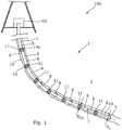
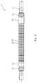
- Fig. 1shows a downhole production casing string 1 during insertion in a borehole 2 in a reservoir 3.
- the boreholehas been drilled and the drill string pulled out of the well before the downhole production casing string 1 is inserted.
- the downhole production casing stringhas a first end 4 nearest a top of the borehole and a second end 5 furthest away from the top.
- the downhole production casing stringextends along a longitudinal axis 6 which is substantially coincident with the longitudinal axis of the borehole.
- the downhole production casing stringextends all the way to the top of the well, but the first end 4 of the production casing string may also be connected with a drill pipe or another tubular for insertion of the production casing string into the borehole.
- the downhole production casing string 1comprises an opening 7 through which hydrocarbon-containing fluid is let into the downhole production casing string from the reservoir in order to produce oil or gas.
- the downhole production casing stringis mounted from a plurality of casing parts 8.
- the casing partshave end sections 9 and a base section 10 between the end sections forming one pipe section.
- An annular projecting element 11is arranged between the casing parts 8 connecting two adjacent casing parts.
- Each annular projecting element 11has an outer face 12 and at least one helical groove 14a arranged in the outer face.
- each annular projecting element 11has an overall outer diameter D oo which is larger than the outer diameter of the base section, so that when the production casing string is inserted in the borehole, the annular projecting elements 11 are the elements hitting against the wall of the borehole.
- the stringis rotated as indicated by the arrows, and since each annular projecting element 11 has helical grooves, the annular projecting elements 11 function as a screw easing the implementation of the production casing string in the borehole.
- the wallhas a lot of rock projections which may prevent free passage of known production casing strings.
- annular projecting elements 11By having annular projecting elements 11 with a helical groove, the production casing string can easily be screwed past these borehole projections, and thus the risk of the production casing string getting stuck in the borehole during insertion is substantially reduced. Furthermore, when inserting the production casing string, the annular projecting elements 11 may hit against the borehole projections and in this way release the tip of the borehole projection from the remaining part, easing the passage of the production casing string further down the borehole. In this way, the annular projecting elements function to even out some of the irregularities of the borehole during the insertion of the downhole production casing string. As the production casing string is inserted and the annular projecting elements hit against the rock projections, the annular projecting elements 11 of the production casing string also protect other completion components in the production casing string by clearing the path.
- the downhole production casing string system 100 shown in Fig. 1comprises the aforementioned production casing string and a rotation equipment 50 for rotating the production casing string along the helical groove as the production casing string is inserted into the borehole.
- the rotation equipment 50is arranged on a derrick but may also be arranged on any suitable rig or vessel.
- the casing partsare assembled with the annular projecting elements 11 above the rotation equipment 50 and subsequently inserted in the borehole, and new casing parts are mounted onto the production casing string 1.
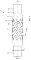
- the annular projecting elements 11are casing collars connecting the casing parts 8.
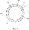
- the annular projecting elements 11have helical grooves as shown in Fig. 2 , where each groove extends partly around the outer face 12 of the annular projecting element 11 covering the whole circumference of the outer face 12 of the annular projecting element 11 as shown in cross-section in Fig. 3 .
- the base section of the casing partshas an outer diameter D o
- the annular projecting element 11has an outer diameter which is the overall outer diameter D oo of the production casing string, and which is larger than the outer diameter of the base section of the casing parts.
- the casing partshave end sections 9 and a base section 10 between the end sections 9, and the end sections 9 are connected to the annular projecting elements 11 by a threaded connection.
- an openingis arranged for letting well fluid into the production casing string during production, or for jetting fracturing fluid out of the production casing string in order to fracture the formation.
- the well fluidis allowed to flow along the groove, and the groove thus provides a fluid channel in the event that the annular projecting element 11 abuts the wall of the borehole.
- the groovesare used for distribution of the fracturing fluid all the way around the circumference of the annular projecting element 11. As shown in Fig. 2 , the groove tapers towards the first end and the second end of the production casing string, so that fluid can always flow into the groove.
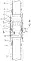
- the annular projecting element 11has an internal groove 31 in which a sliding sleeve 32 is arranged, as shown in Fig. 4a .
- the sliding sleevehas indentations for matching a key tool in order to open and close the sleeve by sliding the sliding sleeve back and forth to cover and uncover the opening.
- the openinghas an angle in relation to the longitudinal axis, shown as the opening having an angle ⁇ in relation to a radial direction transverse to the longitudinal axis, so that the hydrocarbon-containing fluid is guided into the production casing string in the angle different from 90°.
- the angleis approximately 45° in Fig. 4a , but in another embodiment, the angle may be 10-80°, preferably 25-75°, more preferably 35-55°. In this way, when entering the production casing string, the fluid is not jetted directly into the wall opposite the opening, and therefore wear on the wall is significantly reduced.
- the angled openingmay also be part of an insert 51 which is inserted in an opening in the annular projecting element 11 as shown in Fig 4b .
- the insertmay be made of ceramic material or tungsten carbide.
- the annular projecting element 11further has indentations 53, matching dogs 52 or similar elements which are forced outwards by a spring, so that when the dogs of the sliding sleeve are arranged opposite an indentation 53, the dogs engage the indentation.
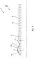
- the annular projecting element 11tapers towards the first end 4 and the second end 5 of the production casing string.
- the annular projecting element 11has a decreasing thickness towards the casing parts and in the area where the annular projecting element 11 and the casing parts engage by the threaded connection 33.
- the helical groove arranged closest to the second and bottom end of the production casing stringis provided with a cutting edge 34, so that when the edge 35 of the groove hits against a projection in the borehole wall that projection is cut off.
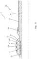
- the annular projecting element 11is part of an annular barrier.
- the annular barriercomprises a casing part 8, an expandable sleeve 15 surrounding the casing part and having an inner sleeve face 16 facing the casing part and an outer sleeve face 17 facing the borehole.
- Each end 18, 19 of the expandable sleeveis connected with the casing part in two connections 22 defining an annular space 20 between the inner sleeve face of the expandable sleeve and the casing part.
- the annular projecting element 11is arranged on an outer casing face 23 and constitutes one of the connections 22, namely the one connection closest to the second end of the production casing string and thus in front of the annular barrier, when inserted into the borehole.
- an annular projecting element 11is arranged in each end of the expandable sleeve 15 for connecting the sleeve 15 to the casing part 8.
- the annular projecting element 11constitutes a connection part 22 overlapping the ends 18, 19 of the sleeve, so that the sleeve is sandwiched between the annular projecting element 11 and the casing part 8.
- the outer diameter of the annular projecting element 11is larger than the outer diameter D o of the connections in the area overlapping the sleeve.
- Sealing means 24are arranged on the outer face 17 of the sleeve 15 for providing a good seal against the borehole when the expandable sleeve is expanded by letting fluid into the space through the expansion opening 21 as indicated by the dotted line.
- the annular projecting element 11 of Fig. 6has thus no opening in connection with the groove.
- the annular projecting element 11is also part of the connection part 22 connecting the expandable sleeve to the casing part 8. Furthermore, openings 7 are arranged in each groove 14a. The openings are joined in a common flow channel in fluid communication with the inside of the production casing string if the sliding sleeve is in its open position. The sliding sleeve is shown in its open position in Fig. 7 .
- the annular projecting element 11 and the connection 22 or connection part 22may also be two separate elements as shown in Figs. 8 and 9 .
- the thickness t 1 of the annular projecting element 11is larger than the thickness t 2 of the connection or connection part 22.
- the annular projecting element 11is a separate component easily mounted on the outer face of the casing part in connection with an annular barrier in order to protect the annular barrier while the production casing string is inserted into the borehole.
- the annular projecting element 11comprises a plurality of openings for jetting fracturing fluid or letting well fluid flow into the production casing string.
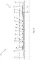
- Fig. 10shows a production casing string having two annular barriers and three annular projecting elements 11 arranged between them.
- the number of annular projecting elements 11depends on the length of each annular barrier, and thus the production casing string can be mounted to fit a variety of boreholes and completion designs.
- the opening 7is arranged closer to the second end of the production casing string than to the first end of the production casing string.
- the openingsmay also be arranged closer to the first end of the production casing string than to the second end of the production casing string, as shown in the left side of Fig. 10 .
- the openingsare not filled with particles during insertion of the production casing string.
- fluid or well fluidany kind of fluid that may be present in oil or gas wells downhole, such as natural gas, oil, oil mud, crude oil, water, etc.
- gasis meant any kind of gas composition present in a well, completion, or open hole
- oilis meant any kind of oil composition, such as crude oil, an oil-containing fluid, etc.
- Gas, oil, and water fluidsmay thus all comprise other elements or substances than gas, oil, and/or water, respectively.
- a casingany kind of pipe, tubing, tubular, liner, string etc. used downhole in relation to oil or natural gas production.
Landscapes
- Engineering & Computer Science (AREA)
- Life Sciences & Earth Sciences (AREA)
- Geology (AREA)
- Mining & Mineral Resources (AREA)
- Physics & Mathematics (AREA)
- Environmental & Geological Engineering (AREA)
- Fluid Mechanics (AREA)
- General Life Sciences & Earth Sciences (AREA)
- Geochemistry & Mineralogy (AREA)
- Mechanical Engineering (AREA)
- Earth Drilling (AREA)
- Placing Or Removing Of Piles Or Sheet Piles, Or Accessories Thereof (AREA)
Description
- The present invention relates to a downhole production casing string for insertion in a borehole in a reservoir. Furthermore, the invention relates to a downhole production casing string system for completing a well downhole and to a method of implementing a production casing string according to the invention.
- Oil and gas wells may have a variety of completion designs depending on the reservoir conditions. Most of the wells have a metal tubing, e.g. known from
EP2466065 . Such tubing may also be called a casing, which is entered into a drilled borehole, and in some implementations the casing gets stuck, or the packer or annular barriers are not forming a tight zone isolation when set. This sometimes occurs due to the fact that the drilling operation results in a borehole having a plurality of projections which prevent free passage of the casing. - It is an object of the present invention to wholly or partly overcome the above disadvantages and drawbacks of the prior art. More specifically, it is an object to provide an improved casing string which is easier to implement in a borehole, also when the production casing string has annular barriers.
- The above objects, together with numerous other objects, advantages and features, which will become evident from the below description, are accomplished by a solution in accordance with the present invention by a downhole production casing string for insertion in a borehole in a reservoir, the downhole production casing string having a first end nearest a top of the borehole and a second end furthest away from the top, the downhole production casing string extending along a longitudinal axis and comprising:
- at least one opening which during production allows hydrocarbon-containing fluid from the reservoir into the downhole production casing string,
- a plurality of casing parts having end sections and a base section between the end sections, the base section having an outer diameter, and
- at least one annular projecting element having an outer face and at least one helical groove arranged in or on the outer face and having an overall outer diameter which is larger than the outer diameter of the base section.
- The annular projecting element may be a casing collar connecting the casing parts.
- The downhole production casing string as described above may further comprise at least one annular barrier.
- Moreover, the annular projecting element may be arranged between two annular barriers.
- Also, the annular projecting element may be part of an annular barrier.
- The annular barrier may comprise a casing part, an expandable sleeve surrounding the casing part and having an inner sleeve face facing the casing part and an outer sleeve face facing the borehole, each end of the expandable sleeve being connected with the casing part in two connections, and an annular space between the inner sleeve face of the expandable sleeve and the casing part, and wherein the annular projecting element may be arranged on an outer casing face adjacent at least the connection closest to the second end of the production casing string.
- The annular barrier may further comprise a casing part, an expandable sleeve surrounding the casing part and having an inner sleeve face facing the casing part and an outer sleeve face facing the borehole, each end of the expandable sleeve being connected with the casing part in two connections, and an annular space between the inner sleeve face of the expandable sleeve and the casing part, and wherein the annular projecting element at least may constitue the one connection arranged closest to the second end of the production casing string.
- Moreover, the annular projecting element may be arranged in each end of the expandable sleeve for connecting the sleeve to the casing part.
- Additionally, the annular projecting element may constitute a connection part overlapping the ends of the sleeve so that the sleeve is sandwiched between the annular projecting element and the casing part.
- Furthermore, the opening may have an angle in relation to a radial direction transverse to the longitudinal axis so that the hydrocarbon-containing fluid is guided into the production casing string in the angle different from 90°.
- In this way, when entering the production casing string, the fluid may not be jetted directly into the wall opposite the opening, and therefore wear on the wall may be significantly reduced.
- Also, the helical groove may have a cutting edge.
- Further, the annular projecting element may comprise several grooves forming a helix about the longitudinal extension.
- The annular projecting element described above may taper towards the second end of the production casing string.
- The outer diameter of the annular projecting element may be the overall outer diameter of the production casing string.
- Also, the opening may be arranged in the groove for letting fluid from the reservoir into the production casing string.
- Furthermore, the production casing string may have an inner face along which a sliding sleeve may be slidably arranged for sliding between a closed position, in which the sliding sleeve may block the opening, and an open position, in which the fluid may be allowed to flow through the opening and into the production casing string.
- The opening may be arranged closer to the first end of the production casing string than to the second end of the production casing string, or closer to the second end of the production casing string than to the first end of the production casing string.
- Moreover, the groove may have an angle in relation to the longitudinal axis, wherein the angle may be 10-80°, preferably 25-75°, more preferably 35-55°.
- Also, the groove may taper towards the first and/or second end of the production casing string.
- Furthermore, the annular projecting element may have threads for being connected to the casing parts.
- The invention also relates to a downhole production casing string system for completing a well downhole, comprising:
- a production casing string according to any of the preceding claims, and
- a rotation equipment for rotating the production casing string along the helical groove as the production casing string is inserted into the borehole.
- Finally, the present invention relates to a method of implementing a production casing string according to the invention in a borehole downhole, comprising the following steps:
- connecting casing parts and at least one annular projecting element for forming the production casing string,
- entering the production casing string into the borehole as the casing parts are assembled, and
- rotating the production casing string along the helical groove as the production casing string enters the borehole.
- Said method may further comprise the step of detaching part of a wall of the borehole from the wall by cutting in or hitting against the borehole wall by means of the annular projecting element.
- Moreover, the method as described above may comprise the step of allowing fluid to flow from the borehole, in through an opening in the annular projecting element, and into the downhole production casing string.
- The method may further comprise the step of increasing an inner diameter of the borehole as the edge of the groove hits against the borehole wall.
- The invention and its many advantages will be described in more detail below with reference to the accompanying schematic drawings, which for the purpose of illustration show some non-limiting embodiments and in which:
Fig. 1 shows a downhole production casing string system for completing a well downhole having a production casing string,Fig. 2 shows an annular projection element as part of a casing collar,Fig. 3 shows a cross-sectional view of the production casing string ofFig. 2 transverse to a longitudinal extension,Fig. 4a shows a cross-sectional view of the production casing string ofFig. 2 along the longitudinal extension,Fig. 4b shows a cross-sectional view of the production casing string along its longitudinal extension,Fig. 5 shows a production casing string having an annular barrier,Fig. 6 shows a cross-sectional view of the production casing string having an annular barrier,Fig. 7 shows a cross-sectional view of another annular barrier having an annular projection element,Fig. 8 shows a cross-sectional view of an annular barrier having another annular projection element,Fig. 9 shows a cross-sectional view of an annular barrier having another annular projection element, andFig. 10 shows a production casing string having two annular barriers.- All the figures are highly schematic and not necessarily to scale, and they show only those parts which are necessary in order to elucidate the invention, other parts being omitted or merely suggested.
Fig. 1 shows a downholeproduction casing string 1 during insertion in aborehole 2 in areservoir 3. The borehole has been drilled and the drill string pulled out of the well before the downholeproduction casing string 1 is inserted. The downhole production casing string has afirst end 4 nearest a top of the borehole and asecond end 5 furthest away from the top. The downhole production casing string extends along alongitudinal axis 6 which is substantially coincident with the longitudinal axis of the borehole. The downhole production casing string extends all the way to the top of the well, but thefirst end 4 of the production casing string may also be connected with a drill pipe or another tubular for insertion of the production casing string into the borehole.- The downhole
production casing string 1 comprises anopening 7 through which hydrocarbon-containing fluid is let into the downhole production casing string from the reservoir in order to produce oil or gas. The downhole production casing string is mounted from a plurality ofcasing parts 8. The casing parts haveend sections 9 and abase section 10 between the end sections forming one pipe section. An annular projectingelement 11 is arranged between thecasing parts 8 connecting two adjacent casing parts. Each annular projectingelement 11 has anouter face 12 and at least onehelical groove 14a arranged in the outer face. The base section has an outer diameter Do, and each annular projectingelement 11 has an overall outer diameter Doo which is larger than the outer diameter of the base section, so that when the production casing string is inserted in the borehole, the annular projectingelements 11 are the elements hitting against the wall of the borehole. The string is rotated as indicated by the arrows, and since each annular projectingelement 11 has helical grooves, the annular projectingelements 11 function as a screw easing the implementation of the production casing string in the borehole. When drilling a borehole, the wall has a lot of rock projections which may prevent free passage of known production casing strings. By having annular projectingelements 11 with a helical groove, the production casing string can easily be screwed past these borehole projections, and thus the risk of the production casing string getting stuck in the borehole during insertion is substantially reduced. Furthermore, when inserting the production casing string, the annular projectingelements 11 may hit against the borehole projections and in this way release the tip of the borehole projection from the remaining part, easing the passage of the production casing string further down the borehole. In this way, the annular projecting elements function to even out some of the irregularities of the borehole during the insertion of the downhole production casing string. As the production casing string is inserted and the annular projecting elements hit against the rock projections, the annular projectingelements 11 of the production casing string also protect other completion components in the production casing string by clearing the path. - The downhole production
casing string system 100 shown inFig. 1 comprises the aforementioned production casing string and arotation equipment 50 for rotating the production casing string along the helical groove as the production casing string is inserted into the borehole. Therotation equipment 50 is arranged on a derrick but may also be arranged on any suitable rig or vessel. The casing parts are assembled with the annular projectingelements 11 above therotation equipment 50 and subsequently inserted in the borehole, and new casing parts are mounted onto theproduction casing string 1. - In
Figs. 1 and2 , the annular projectingelements 11 are casing collars connecting thecasing parts 8. The annular projectingelements 11 have helical grooves as shown inFig. 2 , where each groove extends partly around theouter face 12 of the annular projectingelement 11 covering the whole circumference of theouter face 12 of the annular projectingelement 11 as shown in cross-section inFig. 3 . As shown inFig. 2 , the base section of the casing parts has an outer diameter Do, and the annular projectingelement 11 has an outer diameter which is the overall outer diameter Doo of the production casing string, and which is larger than the outer diameter of the base section of the casing parts. - As can be seen in
Fig. 4a , the casing parts haveend sections 9 and abase section 10 between theend sections 9, and theend sections 9 are connected to the annular projectingelements 11 by a threaded connection. In one of the grooves, an opening is arranged for letting well fluid into the production casing string during production, or for jetting fracturing fluid out of the production casing string in order to fracture the formation. When the opening is used for production, the well fluid is allowed to flow along the groove, and the groove thus provides a fluid channel in the event that the annular projectingelement 11 abuts the wall of the borehole. If the opening is used for letting out fracturing fluid and into the formation, the grooves are used for distribution of the fracturing fluid all the way around the circumference of the annular projectingelement 11. As shown inFig. 2 , the groove tapers towards the first end and the second end of the production casing string, so that fluid can always flow into the groove. - The annular projecting
element 11 has aninternal groove 31 in which a slidingsleeve 32 is arranged, as shown inFig. 4a . The sliding sleeve has indentations for matching a key tool in order to open and close the sleeve by sliding the sliding sleeve back and forth to cover and uncover the opening. - In
Fig. 4a , the opening has an angle in relation to the longitudinal axis, shown as the opening having an angle β in relation to a radial direction transverse to the longitudinal axis, so that the hydrocarbon-containing fluid is guided into the production casing string in the angle different from 90°. The angle is approximately 45° inFig. 4a , but in another embodiment, the angle may be 10-80°, preferably 25-75°, more preferably 35-55°. In this way, when entering the production casing string, the fluid is not jetted directly into the wall opposite the opening, and therefore wear on the wall is significantly reduced. - The angled opening may also be part of an
insert 51 which is inserted in an opening in the annular projectingelement 11 as shown inFig 4b . The insert may be made of ceramic material or tungsten carbide. The annular projectingelement 11 further hasindentations 53, matchingdogs 52 or similar elements which are forced outwards by a spring, so that when the dogs of the sliding sleeve are arranged opposite anindentation 53, the dogs engage the indentation. - As can be seen in
Fig. 1 , the annular projectingelement 11 tapers towards thefirst end 4 and thesecond end 5 of the production casing string. Thus, as shown in the cross-sectional view inFigs. 4a and4b , the annular projectingelement 11 has a decreasing thickness towards the casing parts and in the area where the annular projectingelement 11 and the casing parts engage by the threadedconnection 33. The helical groove arranged closest to the second and bottom end of the production casing string is provided with acutting edge 34, so that when theedge 35 of the groove hits against a projection in the borehole wall that projection is cut off. Thus, while inserting the production casing string having annular projectingelements 11, the inner diameter of the borehole is evened out. By being able to even out the borehole, packers or annular barriers being part of the production casing string can more easily be successfully set later on, as they are to abut the wall of the borehole to provide the zone isolation. - In
Fig. 5 , the annular projectingelement 11 is part of an annular barrier. As shown inFig. 6 , the annular barrier comprises acasing part 8, anexpandable sleeve 15 surrounding the casing part and having aninner sleeve face 16 facing the casing part and anouter sleeve face 17 facing the borehole. Eachend connections 22 defining anannular space 20 between the inner sleeve face of the expandable sleeve and the casing part. The annular projectingelement 11 is arranged on anouter casing face 23 and constitutes one of theconnections 22, namely the one connection closest to the second end of the production casing string and thus in front of the annular barrier, when inserted into the borehole. InFig. 5 , an annular projectingelement 11 is arranged in each end of theexpandable sleeve 15 for connecting thesleeve 15 to thecasing part 8. As shown inFig. 6 , the annular projectingelement 11 constitutes aconnection part 22 overlapping theends element 11 and thecasing part 8. The outer diameter of the annular projectingelement 11 is larger than the outer diameter Do of the connections in the area overlapping the sleeve. Sealing means 24 are arranged on theouter face 17 of thesleeve 15 for providing a good seal against the borehole when the expandable sleeve is expanded by letting fluid into the space through theexpansion opening 21 as indicated by the dotted line. The annular projectingelement 11 ofFig. 6 has thus no opening in connection with the groove. - In
Fig. 7 , the annular projectingelement 11 is also part of theconnection part 22 connecting the expandable sleeve to thecasing part 8. Furthermore,openings 7 are arranged in eachgroove 14a. The openings are joined in a common flow channel in fluid communication with the inside of the production casing string if the sliding sleeve is in its open position. The sliding sleeve is shown in its open position inFig. 7 . - The annular projecting
element 11 and theconnection 22 orconnection part 22 may also be two separate elements as shown inFigs. 8 and9 . The thickness t1 of the annular projectingelement 11 is larger than the thickness t2 of the connection orconnection part 22. InFig. 9 , the annular projectingelement 11 is a separate component easily mounted on the outer face of the casing part in connection with an annular barrier in order to protect the annular barrier while the production casing string is inserted into the borehole. The annular projectingelement 11 comprises a plurality of openings for jetting fracturing fluid or letting well fluid flow into the production casing string. Fig. 10 shows a production casing string having two annular barriers and three annular projectingelements 11 arranged between them. The number of annular projectingelements 11 depends on the length of each annular barrier, and thus the production casing string can be mounted to fit a variety of boreholes and completion designs.- As shown in the right side of
Fig. 10 , theopening 7 is arranged closer to the second end of the production casing string than to the first end of the production casing string. The openings may also be arranged closer to the first end of the production casing string than to the second end of the production casing string, as shown in the left side ofFig. 10 . By having the openings arranged closer to the first end of the production casing string than to the second end of the production casing string, the openings are not filled with particles during insertion of the production casing string. By arranging the openings at a distance from the centre of the annular projectingelement 11, the fluid may flow more easily into the production casing string. - By fluid or well fluid is meant any kind of fluid that may be present in oil or gas wells downhole, such as natural gas, oil, oil mud, crude oil, water, etc. By gas is meant any kind of gas composition present in a well, completion, or open hole, and by oil is meant any kind of oil composition, such as crude oil, an oil-containing fluid, etc. Gas, oil, and water fluids may thus all comprise other elements or substances than gas, oil, and/or water, respectively.
- By a casing is meant any kind of pipe, tubing, tubular, liner, string etc. used downhole in relation to oil or natural gas production.
- Although the invention has been described in the above in connection with preferred embodiments of the invention, it will be evident for a person skilled in the art that several modifications are conceivable without departing from the invention as defined by the following claims.
Claims (12)
- A downhole production casing string (1) for insertion in a borehole (2) in a reservoir (3), the downhole production casing string having a first end (4) nearest a top of the borehole and a second end (5) furthest away from the top, the downhole production casing string extending along a longitudinal axis (6) and comprising:- at least one opening (7) which during production allows hydrocarbon-containing fluid from the reservoir into the downhole production casing string,- a plurality of casing parts (8) having end sections (9) and a base section (10) between the end sections, the base section having an outer diameter (Do), and- at least one annular barrier (24),wherein the annular barrier comprises a casing part (8), an expandable sleeve (15) surrounding the casing part and having an inner sleeve face (16) facing the casing part and an outer sleeve face (17) facing the borehole, each end (18, 19) of the expandable sleeve being connected with the casing part in two connections (22), and an annular space (20) between the inner sleeve face of the expandable sleeve and the casing part,
characterised in that the downhole production casing string further comprises:- at least one annular projecting element (11) having an outer face (12) and at least one helical groove (14a) arranged in or on the outer face and having an overall outer diameter (Doo) which is larger than the outer diameter of the connections (22) in the area overlapping the sleeve, and wherein the annular projecting element is arranged on an outer casing face (23) of the casing part adjacent or constituting the connection closest to the second end (5) of the production casing string. - A downhole production casing string (1) according to claim 1, wherein the annular projecting element is a casing collar connecting the casing parts.
- A downhole production casing string (1) according to claim 1, wherein the annular projecting element is arranged between two annular barriers.
- A downhole production casing string (1) according to claim 1, wherein the annular projecting element is part of the annular barrier (24).
- A downhole production casing string (1) according to any of the preceding claims, wherein the opening has an angle (β) in relation to a radial direction transverse to the longitudinal axis so that the hydrocarbon-containing fluid is guided into the production casing string in the angle different from 90°.
- A downhole production casing string (1) according to any of the preceding claims, wherein the helical groove has a cutting edge (34).
- A downhole production casing string (1) according to any of the preceding claims, wherein the annular projecting element comprises several grooves forming a helix about the longitudinal extension.
- A downhole production casing string (1) according to any of the preceding claims, wherein the annular projecting element tapers towards the second end of the production casing string.
- A downhole production casing string (1) according to any of the preceding claims, wherein the outer diameter of the annular projecting element is the overall outer diameter of the production casing string.
- A downhole production casing string (1) according to any of the preceding claims, wherein the opening is arranged in the groove for letting fluid from the reservoir into the production casing string.
- A downhole production casing string system (100) for completing a well downhole, comprising:- a production casing string (1) according to any of the preceding claims, and- a rotation equipment (50) for rotating the production casing string along the helical groove as the production casing string is inserted into the borehole.
- A method of implementing a production casing string (1) according to any of claims 1-10 in a borehole downhole, comprising the following steps:- connecting casing parts (8) and at least one annular projecting element (11) for forming the production casing string,- entering the production casing string into the borehole as the casing parts are assembled, and- rotating the production casing string along the helical groove as the production casing string enters the borehole.
Priority Applications (1)
| Application Number | Priority Date | Filing Date | Title |
|---|---|---|---|
| EP14808567.3AEP3080386B1 (en) | 2013-11-29 | 2014-11-28 | A downhole production casing string |
Applications Claiming Priority (3)
| Application Number | Priority Date | Filing Date | Title |
|---|---|---|---|
| EP13195030.5AEP2878763A1 (en) | 2013-11-29 | 2013-11-29 | A downhole casing string |
| EP14808567.3AEP3080386B1 (en) | 2013-11-29 | 2014-11-28 | A downhole production casing string |
| PCT/EP2014/075892WO2015079003A2 (en) | 2013-11-29 | 2014-11-28 | A downhole production casing string |
Publications (2)
| Publication Number | Publication Date |
|---|---|
| EP3080386A2 EP3080386A2 (en) | 2016-10-19 |
| EP3080386B1true EP3080386B1 (en) | 2020-09-30 |
Family
ID=49680873
Family Applications (2)
| Application Number | Title | Priority Date | Filing Date |
|---|---|---|---|
| EP13195030.5AWithdrawnEP2878763A1 (en) | 2013-11-29 | 2013-11-29 | A downhole casing string |
| EP14808567.3AActiveEP3080386B1 (en) | 2013-11-29 | 2014-11-28 | A downhole production casing string |
Family Applications Before (1)
| Application Number | Title | Priority Date | Filing Date |
|---|---|---|---|
| EP13195030.5AWithdrawnEP2878763A1 (en) | 2013-11-29 | 2013-11-29 | A downhole casing string |
Country Status (11)
| Country | Link |
|---|---|
| US (1) | US11572740B2 (en) |
| EP (2) | EP2878763A1 (en) |
| CN (1) | CN105723050A (en) |
| AU (1) | AU2014356431B2 (en) |
| BR (1) | BR112016010496B1 (en) |
| CA (1) | CA2930758A1 (en) |
| DK (1) | DK3080386T3 (en) |
| MX (1) | MX2016006628A (en) |
| MY (1) | MY176649A (en) |
| RU (1) | RU2677178C1 (en) |
| WO (1) | WO2015079003A2 (en) |
Families Citing this family (6)
| Publication number | Priority date | Publication date | Assignee | Title |
|---|---|---|---|---|
| WO2016044923A1 (en)* | 2014-09-26 | 2016-03-31 | Ncs Multistage Inc. | Downhole valve apparatus |
| US11354168B2 (en) | 2019-01-18 | 2022-06-07 | Salesforce.Com, Inc. | Elastic data partitioning of a database |
| CA3200943A1 (en)* | 2020-12-21 | 2022-06-30 | Diaset Products Ltd. | Core barrel and core drilling systems and methods |
| CN112855027B (en)* | 2021-02-06 | 2022-05-17 | 中国地质科学院勘探技术研究所 | Through type running-in method for deep sea expansion corrugated pipe |
| CN115822509A (en)* | 2022-06-24 | 2023-03-21 | 中国石油天然气集团有限公司 | Rubber combined sleeve for oil and gas development |
| US20250172047A1 (en)* | 2023-11-27 | 2025-05-29 | Jarod Colson | System, Method, and Apparatus for Centralizing a Downhole Casing and Connecting Portions Thereof |
Citations (2)
| Publication number | Priority date | Publication date | Assignee | Title |
|---|---|---|---|---|
| EP2466065A1 (en)* | 2010-12-17 | 2012-06-20 | Welltec A/S | Well completion |
| US20120152523A1 (en)* | 2010-09-09 | 2012-06-21 | Summit Downhole Dynamics, Ltd. | Self-Orienting Fracturing Sleeve and System |
Family Cites Families (26)
| Publication number | Priority date | Publication date | Assignee | Title |
|---|---|---|---|---|
| US3476415A (en)* | 1967-10-06 | 1969-11-04 | Servco Co | Coupling |
| US3560060A (en)* | 1968-12-18 | 1971-02-02 | Nate Morris | Rod guide and centralizer |
| SU802506A1 (en) | 1978-11-04 | 1981-02-07 | Московский Ордена Трудового Красногознамени Геологоразведочный Институтим.C.Орджоникидзе | Casing column of well |
| US4529045A (en)* | 1984-03-26 | 1985-07-16 | Varco International, Inc. | Top drive drilling unit with rotatable pipe support |
| US4664206A (en)* | 1985-09-23 | 1987-05-12 | Gulf Canada Corporation | Stabilizer for drillstems |
| US5139094A (en)* | 1991-02-01 | 1992-08-18 | Anadrill, Inc. | Directional drilling methods and apparatus |
| GB9211946D0 (en)* | 1992-06-05 | 1992-07-15 | Panther Oil Tools Uk Ltd | Backreaming stabilizer |
| US5697442A (en)* | 1995-11-13 | 1997-12-16 | Halliburton Company | Apparatus and methods for use in cementing a casing string within a well bore |
| FR2789438B1 (en)* | 1999-02-05 | 2001-05-04 | Smf Internat | PROFILE ELEMENT FOR ROTARY DRILLING EQUIPMENT AND DRILLING ROD WITH AT LEAST ONE PROFILED SECTION |
| GB0016146D0 (en) | 2000-06-30 | 2000-08-23 | Brunel Oilfield Serv Uk Ltd | Improvements in or relating to downhole tools |
| CA2412072C (en)* | 2001-11-19 | 2012-06-19 | Packers Plus Energy Services Inc. | Method and apparatus for wellbore fluid treatment |
| FR2835014B1 (en) | 2002-01-18 | 2004-07-16 | Smf Internat | PROFILE ELEMENT FOR ROTARY DRILLING EQUIPMENT AND DRILL ROD COMPRISING AT LEAST ONE PROFILE ELEMENT |
| DE60325200D1 (en)* | 2002-04-18 | 2009-01-22 | Nicholas P Valenti | BOREHOLE PREPARATION WITH UNITED AFFECTION OF DRILLING LIQUIDS |
| CN2573664Y (en) | 2002-07-18 | 2003-09-17 | 栾传振 | External pipe packer |
| FR2843418B1 (en)* | 2002-08-08 | 2005-12-16 | Smf Internat | DEVICE FOR STABILIZING A ROTARY DRILL ROD TRAIN WITH REDUCED FRICTION |
| RU31146U1 (en) | 2003-03-24 | 2003-07-20 | Закрытое акционерное общество "Самарские Горизонты" | PIPE COLUMN |
| CA2486279C (en)* | 2003-10-29 | 2010-10-05 | Weatherford/Lamb, Inc. | Vibration damper systems for drilling with casing |
| US7114562B2 (en)* | 2003-11-24 | 2006-10-03 | Schlumberger Technology Corporation | Apparatus and method for acquiring information while drilling |
| US20070163778A1 (en)* | 2006-01-19 | 2007-07-19 | Jim Wheeler | Casing Centralizer Coupling |
| CA2533563A1 (en)* | 2006-01-20 | 2007-07-20 | Jim Wheeler | Casing centralizer coupling |
| GB0805216D0 (en)* | 2008-03-20 | 2008-04-30 | Flotech Ltd | Flow restrictor |
| ES2464457T3 (en)* | 2009-01-12 | 2014-06-02 | Welltec A/S | Annular barrier and annular barrier system |
| US8695716B2 (en)* | 2009-07-27 | 2014-04-15 | Baker Hughes Incorporated | Multi-zone fracturing completion |
| BRPI1006152B1 (en)* | 2009-11-13 | 2019-11-26 | Wwt Int Inc | non-rotating downhole sleeve and torque reduction method |
| GB2490924B (en)* | 2011-05-18 | 2013-07-10 | Volnay Engineering Services Ltd | Improvements in and relating to downhole tools |
| US20130233620A1 (en)* | 2012-03-09 | 2013-09-12 | Rite Increaser, LLC | Stabilizer with Drilling Fluid Diverting Ports |
- 2013
- 2013-11-29EPEP13195030.5Apatent/EP2878763A1/ennot_activeWithdrawn
- 2014
- 2014-11-28CNCN201480062240.2Apatent/CN105723050A/enactivePending
- 2014-11-28CACA2930758Apatent/CA2930758A1/ennot_activeAbandoned
- 2014-11-28DKDK14808567.3Tpatent/DK3080386T3/enactive
- 2014-11-28WOPCT/EP2014/075892patent/WO2015079003A2/enactiveApplication Filing
- 2014-11-28AUAU2014356431Apatent/AU2014356431B2/enactiveActive
- 2014-11-28RURU2016123344Apatent/RU2677178C1/enactive
- 2014-11-28USUS15/039,146patent/US11572740B2/enactiveActive
- 2014-11-28MXMX2016006628Apatent/MX2016006628A/enactiveIP Right Grant
- 2014-11-28EPEP14808567.3Apatent/EP3080386B1/enactiveActive
- 2014-11-28BRBR112016010496-0Apatent/BR112016010496B1/enactiveIP Right Grant
- 2014-11-28MYMYPI2016000709Apatent/MY176649A/enunknown
Patent Citations (2)
| Publication number | Priority date | Publication date | Assignee | Title |
|---|---|---|---|---|
| US20120152523A1 (en)* | 2010-09-09 | 2012-06-21 | Summit Downhole Dynamics, Ltd. | Self-Orienting Fracturing Sleeve and System |
| EP2466065A1 (en)* | 2010-12-17 | 2012-06-20 | Welltec A/S | Well completion |
Also Published As
| Publication number | Publication date |
|---|---|
| AU2014356431B2 (en) | 2017-03-30 |
| BR112016010496A2 (en) | 2017-08-08 |
| WO2015079003A2 (en) | 2015-06-04 |
| BR112016010496B1 (en) | 2021-11-03 |
| CA2930758A1 (en) | 2015-06-04 |
| US11572740B2 (en) | 2023-02-07 |
| EP2878763A1 (en) | 2015-06-03 |
| WO2015079003A3 (en) | 2015-07-23 |
| MY176649A (en) | 2020-08-19 |
| RU2016123344A (en) | 2018-01-09 |
| CN105723050A (en) | 2016-06-29 |
| US20170016278A1 (en) | 2017-01-19 |
| AU2014356431A1 (en) | 2016-07-07 |
| MX2016006628A (en) | 2016-08-08 |
| EP3080386A2 (en) | 2016-10-19 |
| RU2677178C1 (en) | 2019-01-15 |
| DK3080386T3 (en) | 2020-11-30 |
Similar Documents
| Publication | Publication Date | Title |
|---|---|---|
| EP3080386B1 (en) | A downhole production casing string | |
| US11346173B2 (en) | Milling apparatus | |
| US20150354306A1 (en) | Downhole tool with expandable stabilizer and underreamer | |
| NO342141B1 (en) | Actuation assembly for use with a downhole tool in a subterranean borehole, expandable apparatus for use in a subterranean borehole and method for actuating a downhole tool | |
| CA2776145C (en) | Wireless pipe recovery and perforating system | |
| US9752390B2 (en) | Casing window assembly | |
| AU2016225860B2 (en) | Casing window assembly | |
| AU2014262237B2 (en) | Casing window assembly |
Legal Events
| Date | Code | Title | Description |
|---|---|---|---|
| PUAI | Public reference made under article 153(3) epc to a published international application that has entered the european phase | Free format text:ORIGINAL CODE: 0009012 | |
| 17P | Request for examination filed | Effective date:20160610 | |
| AK | Designated contracting states | Kind code of ref document:A2 Designated state(s):AL AT BE BG CH CY CZ DE DK EE ES FI FR GB GR HR HU IE IS IT LI LT LU LV MC MK MT NL NO PL PT RO RS SE SI SK SM TR | |
| AX | Request for extension of the european patent | Extension state:BA ME | |
| DAX | Request for extension of the european patent (deleted) | ||
| STAA | Information on the status of an ep patent application or granted ep patent | Free format text:STATUS: EXAMINATION IS IN PROGRESS | |
| 17Q | First examination report despatched | Effective date:20170731 | |
| RAP1 | Party data changed (applicant data changed or rights of an application transferred) | Owner name:WELLTEC OILFIELD SOLUTIONS AG | |
| REG | Reference to a national code | Ref country code:DE Ref legal event code:R079 Ref document number:602014070802 Country of ref document:DE Free format text:PREVIOUS MAIN CLASS: E21B0033127000 Ipc:E21B0034000000 | |
| RIC1 | Information provided on ipc code assigned before grant | Ipc:E21B 7/20 20060101ALI20191014BHEP Ipc:E21B 34/00 20060101AFI20191014BHEP Ipc:E21B 33/127 20060101ALI20191014BHEP Ipc:E21B 17/08 20060101ALI20191014BHEP Ipc:E21B 17/10 20060101ALI20191014BHEP | |
| GRAP | Despatch of communication of intention to grant a patent | Free format text:ORIGINAL CODE: EPIDOSNIGR1 | |
| STAA | Information on the status of an ep patent application or granted ep patent | Free format text:STATUS: GRANT OF PATENT IS INTENDED | |
| INTG | Intention to grant announced | Effective date:20191210 | |
| GRAJ | Information related to disapproval of communication of intention to grant by the applicant or resumption of examination proceedings by the epo deleted | Free format text:ORIGINAL CODE: EPIDOSDIGR1 | |
| STAA | Information on the status of an ep patent application or granted ep patent | Free format text:STATUS: EXAMINATION IS IN PROGRESS | |
| INTC | Intention to grant announced (deleted) | ||
| RAP1 | Party data changed (applicant data changed or rights of an application transferred) | Owner name:WELLTEC OILFIELD SOLUTIONS AG | |
| GRAP | Despatch of communication of intention to grant a patent | Free format text:ORIGINAL CODE: EPIDOSNIGR1 | |
| STAA | Information on the status of an ep patent application or granted ep patent | Free format text:STATUS: GRANT OF PATENT IS INTENDED | |
| INTG | Intention to grant announced | Effective date:20200507 | |
| GRAS | Grant fee paid | Free format text:ORIGINAL CODE: EPIDOSNIGR3 | |
| GRAA | (expected) grant | Free format text:ORIGINAL CODE: 0009210 | |
| STAA | Information on the status of an ep patent application or granted ep patent | Free format text:STATUS: THE PATENT HAS BEEN GRANTED | |
| AK | Designated contracting states | Kind code of ref document:B1 Designated state(s):AL AT BE BG CH CY CZ DE DK EE ES FI FR GB GR HR HU IE IS IT LI LT LU LV MC MK MT NL NO PL PT RO RS SE SI SK SM TR | |
| REG | Reference to a national code | Ref country code:CH Ref legal event code:EP Ref country code:GB Ref legal event code:FG4D | |
| REG | Reference to a national code | Ref country code:DE Ref legal event code:R096 Ref document number:602014070802 Country of ref document:DE Ref country code:AT Ref legal event code:REF Ref document number:1318967 Country of ref document:AT Kind code of ref document:T Effective date:20201015 | |
| REG | Reference to a national code | Ref country code:IE Ref legal event code:FG4D | |
| REG | Reference to a national code | Ref country code:DK Ref legal event code:T3 Effective date:20201127 | |
| REG | Reference to a national code | Ref country code:NL Ref legal event code:FP | |
| REG | Reference to a national code | Ref country code:NO Ref legal event code:T2 Effective date:20200930 | |
| PGFP | Annual fee paid to national office [announced via postgrant information from national office to epo] | Ref country code:NL Payment date:20201125 Year of fee payment:7 | |
| PG25 | Lapsed in a contracting state [announced via postgrant information from national office to epo] | Ref country code:HR Free format text:LAPSE BECAUSE OF FAILURE TO SUBMIT A TRANSLATION OF THE DESCRIPTION OR TO PAY THE FEE WITHIN THE PRESCRIBED TIME-LIMIT Effective date:20200930 Ref country code:GR Free format text:LAPSE BECAUSE OF FAILURE TO SUBMIT A TRANSLATION OF THE DESCRIPTION OR TO PAY THE FEE WITHIN THE PRESCRIBED TIME-LIMIT Effective date:20201231 Ref country code:FI Free format text:LAPSE BECAUSE OF FAILURE TO SUBMIT A TRANSLATION OF THE DESCRIPTION OR TO PAY THE FEE WITHIN THE PRESCRIBED TIME-LIMIT Effective date:20200930 Ref country code:SE Free format text:LAPSE BECAUSE OF FAILURE TO SUBMIT A TRANSLATION OF THE DESCRIPTION OR TO PAY THE FEE WITHIN THE PRESCRIBED TIME-LIMIT Effective date:20200930 Ref country code:BG Free format text:LAPSE BECAUSE OF FAILURE TO SUBMIT A TRANSLATION OF THE DESCRIPTION OR TO PAY THE FEE WITHIN THE PRESCRIBED TIME-LIMIT Effective date:20201230 | |
| PGFP | Annual fee paid to national office [announced via postgrant information from national office to epo] | Ref country code:DE Payment date:20201106 Year of fee payment:7 | |
| REG | Reference to a national code | Ref country code:AT Ref legal event code:MK05 Ref document number:1318967 Country of ref document:AT Kind code of ref document:T Effective date:20200930 | |
| PG25 | Lapsed in a contracting state [announced via postgrant information from national office to epo] | Ref country code:LV Free format text:LAPSE BECAUSE OF FAILURE TO SUBMIT A TRANSLATION OF THE DESCRIPTION OR TO PAY THE FEE WITHIN THE PRESCRIBED TIME-LIMIT Effective date:20200930 Ref country code:RS Free format text:LAPSE BECAUSE OF FAILURE TO SUBMIT A TRANSLATION OF THE DESCRIPTION OR TO PAY THE FEE WITHIN THE PRESCRIBED TIME-LIMIT Effective date:20200930 | |
| REG | Reference to a national code | Ref country code:LT Ref legal event code:MG4D | |
| PG25 | Lapsed in a contracting state [announced via postgrant information from national office to epo] | Ref country code:CZ Free format text:LAPSE BECAUSE OF FAILURE TO SUBMIT A TRANSLATION OF THE DESCRIPTION OR TO PAY THE FEE WITHIN THE PRESCRIBED TIME-LIMIT Effective date:20200930 Ref country code:LT Free format text:LAPSE BECAUSE OF FAILURE TO SUBMIT A TRANSLATION OF THE DESCRIPTION OR TO PAY THE FEE WITHIN THE PRESCRIBED TIME-LIMIT Effective date:20200930 Ref country code:PT Free format text:LAPSE BECAUSE OF FAILURE TO SUBMIT A TRANSLATION OF THE DESCRIPTION OR TO PAY THE FEE WITHIN THE PRESCRIBED TIME-LIMIT Effective date:20210201 Ref country code:EE Free format text:LAPSE BECAUSE OF FAILURE TO SUBMIT A TRANSLATION OF THE DESCRIPTION OR TO PAY THE FEE WITHIN THE PRESCRIBED TIME-LIMIT Effective date:20200930 Ref country code:SM Free format text:LAPSE BECAUSE OF FAILURE TO SUBMIT A TRANSLATION OF THE DESCRIPTION OR TO PAY THE FEE WITHIN THE PRESCRIBED TIME-LIMIT Effective date:20200930 Ref country code:RO Free format text:LAPSE BECAUSE OF FAILURE TO SUBMIT A TRANSLATION OF THE DESCRIPTION OR TO PAY THE FEE WITHIN THE PRESCRIBED TIME-LIMIT Effective date:20200930 | |
| PG25 | Lapsed in a contracting state [announced via postgrant information from national office to epo] | Ref country code:ES Free format text:LAPSE BECAUSE OF FAILURE TO SUBMIT A TRANSLATION OF THE DESCRIPTION OR TO PAY THE FEE WITHIN THE PRESCRIBED TIME-LIMIT Effective date:20200930 Ref country code:AL Free format text:LAPSE BECAUSE OF FAILURE TO SUBMIT A TRANSLATION OF THE DESCRIPTION OR TO PAY THE FEE WITHIN THE PRESCRIBED TIME-LIMIT Effective date:20200930 Ref country code:AT Free format text:LAPSE BECAUSE OF FAILURE TO SUBMIT A TRANSLATION OF THE DESCRIPTION OR TO PAY THE FEE WITHIN THE PRESCRIBED TIME-LIMIT Effective date:20200930 Ref country code:PL Free format text:LAPSE BECAUSE OF FAILURE TO SUBMIT A TRANSLATION OF THE DESCRIPTION OR TO PAY THE FEE WITHIN THE PRESCRIBED TIME-LIMIT Effective date:20200930 Ref country code:IS Free format text:LAPSE BECAUSE OF FAILURE TO SUBMIT A TRANSLATION OF THE DESCRIPTION OR TO PAY THE FEE WITHIN THE PRESCRIBED TIME-LIMIT Effective date:20210130 | |
| PG25 | Lapsed in a contracting state [announced via postgrant information from national office to epo] | Ref country code:SK Free format text:LAPSE BECAUSE OF FAILURE TO SUBMIT A TRANSLATION OF THE DESCRIPTION OR TO PAY THE FEE WITHIN THE PRESCRIBED TIME-LIMIT Effective date:20200930 Ref country code:MC Free format text:LAPSE BECAUSE OF FAILURE TO SUBMIT A TRANSLATION OF THE DESCRIPTION OR TO PAY THE FEE WITHIN THE PRESCRIBED TIME-LIMIT Effective date:20200930 | |
| REG | Reference to a national code | Ref country code:CH Ref legal event code:PL | |
| REG | Reference to a national code | Ref country code:DE Ref legal event code:R097 Ref document number:602014070802 Country of ref document:DE | |
| PG25 | Lapsed in a contracting state [announced via postgrant information from national office to epo] | Ref country code:LU Free format text:LAPSE BECAUSE OF NON-PAYMENT OF DUE FEES Effective date:20201128 | |
| PLBE | No opposition filed within time limit | Free format text:ORIGINAL CODE: 0009261 | |
| STAA | Information on the status of an ep patent application or granted ep patent | Free format text:STATUS: NO OPPOSITION FILED WITHIN TIME LIMIT | |
| REG | Reference to a national code | Ref country code:BE Ref legal event code:MM Effective date:20201130 | |
| PG25 | Lapsed in a contracting state [announced via postgrant information from national office to epo] | Ref country code:LI Free format text:LAPSE BECAUSE OF NON-PAYMENT OF DUE FEES Effective date:20201130 Ref country code:CH Free format text:LAPSE BECAUSE OF NON-PAYMENT OF DUE FEES Effective date:20201130 | |
| 26N | No opposition filed | Effective date:20210701 | |
| PG25 | Lapsed in a contracting state [announced via postgrant information from national office to epo] | Ref country code:IE Free format text:LAPSE BECAUSE OF NON-PAYMENT OF DUE FEES Effective date:20201128 Ref country code:IT Free format text:LAPSE BECAUSE OF FAILURE TO SUBMIT A TRANSLATION OF THE DESCRIPTION OR TO PAY THE FEE WITHIN THE PRESCRIBED TIME-LIMIT Effective date:20200930 | |
| PG25 | Lapsed in a contracting state [announced via postgrant information from national office to epo] | Ref country code:SI Free format text:LAPSE BECAUSE OF FAILURE TO SUBMIT A TRANSLATION OF THE DESCRIPTION OR TO PAY THE FEE WITHIN THE PRESCRIBED TIME-LIMIT Effective date:20200930 | |
| PG25 | Lapsed in a contracting state [announced via postgrant information from national office to epo] | Ref country code:IS Free format text:LAPSE BECAUSE OF FAILURE TO SUBMIT A TRANSLATION OF THE DESCRIPTION OR TO PAY THE FEE WITHIN THE PRESCRIBED TIME-LIMIT Effective date:20210130 Ref country code:TR Free format text:LAPSE BECAUSE OF FAILURE TO SUBMIT A TRANSLATION OF THE DESCRIPTION OR TO PAY THE FEE WITHIN THE PRESCRIBED TIME-LIMIT Effective date:20200930 Ref country code:MT Free format text:LAPSE BECAUSE OF FAILURE TO SUBMIT A TRANSLATION OF THE DESCRIPTION OR TO PAY THE FEE WITHIN THE PRESCRIBED TIME-LIMIT Effective date:20200930 Ref country code:CY Free format text:LAPSE BECAUSE OF FAILURE TO SUBMIT A TRANSLATION OF THE DESCRIPTION OR TO PAY THE FEE WITHIN THE PRESCRIBED TIME-LIMIT Effective date:20200930 | |
| REG | Reference to a national code | Ref country code:DE Ref legal event code:R119 Ref document number:602014070802 Country of ref document:DE | |
| PG25 | Lapsed in a contracting state [announced via postgrant information from national office to epo] | Ref country code:MK Free format text:LAPSE BECAUSE OF FAILURE TO SUBMIT A TRANSLATION OF THE DESCRIPTION OR TO PAY THE FEE WITHIN THE PRESCRIBED TIME-LIMIT Effective date:20200930 | |
| REG | Reference to a national code | Ref country code:NL Ref legal event code:MM Effective date:20211201 | |
| PG25 | Lapsed in a contracting state [announced via postgrant information from national office to epo] | Ref country code:BE Free format text:LAPSE BECAUSE OF NON-PAYMENT OF DUE FEES Effective date:20201130 | |
| PG25 | Lapsed in a contracting state [announced via postgrant information from national office to epo] | Ref country code:NL Free format text:LAPSE BECAUSE OF NON-PAYMENT OF DUE FEES Effective date:20211201 | |
| PG25 | Lapsed in a contracting state [announced via postgrant information from national office to epo] | Ref country code:DE Free format text:LAPSE BECAUSE OF NON-PAYMENT OF DUE FEES Effective date:20220601 | |
| P01 | Opt-out of the competence of the unified patent court (upc) registered | Effective date:20230523 | |
| REG | Reference to a national code | Ref country code:GB Ref legal event code:732E Free format text:REGISTERED BETWEEN 20241017 AND 20241023 | |
| PGFP | Annual fee paid to national office [announced via postgrant information from national office to epo] | Ref country code:NO Payment date:20241120 Year of fee payment:11 | |
| PGFP | Annual fee paid to national office [announced via postgrant information from national office to epo] | Ref country code:DK Payment date:20241120 Year of fee payment:11 | |
| PGFP | Annual fee paid to national office [announced via postgrant information from national office to epo] | Ref country code:GB Payment date:20241118 Year of fee payment:11 | |
| PGFP | Annual fee paid to national office [announced via postgrant information from national office to epo] | Ref country code:FR Payment date:20241115 Year of fee payment:11 |