EP3074745B1 - A leak detector and package integrity testing mechanism and testing method for vacuum-sealed packages - Google Patents
A leak detector and package integrity testing mechanism and testing method for vacuum-sealed packagesDownload PDFInfo
- Publication number
- EP3074745B1 EP3074745B1EP14827561.3AEP14827561AEP3074745B1EP 3074745 B1EP3074745 B1EP 3074745B1EP 14827561 AEP14827561 AEP 14827561AEP 3074745 B1EP3074745 B1EP 3074745B1
- Authority
- EP
- European Patent Office
- Prior art keywords
- seal
- packaging
- frame
- testing
- gusset
- Prior art date
- Legal status (The legal status is an assumption and is not a legal conclusion. Google has not performed a legal analysis and makes no representation as to the accuracy of the status listed.)
- Not-in-force
Links
- 238000012360testing methodMethods0.000titleclaimsdescription49
- 230000007246mechanismEffects0.000titledescription4
- 238000011016integrity testingMethods0.000title1
- 238000004806packaging method and processMethods0.000claimsdescription36
- 238000006073displacement reactionMethods0.000claimsdescription23
- 238000010998test methodMethods0.000claimsdescription6
- 230000000284resting effectEffects0.000claimsdescription4
- 238000012544monitoring processMethods0.000claims2
- 238000000034methodMethods0.000description21
- 235000013351cheeseNutrition0.000description14
- 235000013305foodNutrition0.000description4
- 230000009471actionEffects0.000description3
- 238000009461vacuum packagingMethods0.000description3
- XLYOFNOQVPJJNP-UHFFFAOYSA-NwaterSubstancesOXLYOFNOQVPJJNP-UHFFFAOYSA-N0.000description3
- 241000233866FungiSpecies0.000description2
- 241000533293Sesbania emerusSpecies0.000description2
- 238000011109contaminationMethods0.000description2
- 238000011156evaluationMethods0.000description2
- 239000007789gasSubstances0.000description2
- 238000007654immersionMethods0.000description2
- 230000001939inductive effectEffects0.000description2
- 238000005259measurementMethods0.000description2
- 230000004048modificationEffects0.000description2
- 238000012986modificationMethods0.000description2
- 230000001681protective effectEffects0.000description2
- 239000000700radioactive tracerSubstances0.000description2
- 241000894006BacteriaSpecies0.000description1
- 241001148470aerobic bacillusSpecies0.000description1
- QVGXLLKOCUKJST-UHFFFAOYSA-Natomic oxygenChemical compound[O]QVGXLLKOCUKJST-UHFFFAOYSA-N0.000description1
- 238000001514detection methodMethods0.000description1
- 230000008020evaporationEffects0.000description1
- 238000001704evaporationMethods0.000description1
- 238000012423maintenanceMethods0.000description1
- 239000001301oxygenSubstances0.000description1
- 229910052760oxygenInorganic materials0.000description1
- 239000005022packaging materialSubstances0.000description1
- 238000012858packaging processMethods0.000description1
- 230000009467reductionEffects0.000description1
- 230000032258transportEffects0.000description1
- 238000005303weighingMethods0.000description1
Images


Classifications
- G—PHYSICS
- G01—MEASURING; TESTING
- G01M—TESTING STATIC OR DYNAMIC BALANCE OF MACHINES OR STRUCTURES; TESTING OF STRUCTURES OR APPARATUS, NOT OTHERWISE PROVIDED FOR
- G01M3/00—Investigating fluid-tightness of structures
- G01M3/02—Investigating fluid-tightness of structures by using fluid or vacuum
- G01M3/36—Investigating fluid-tightness of structures by using fluid or vacuum by detecting change in dimensions of the structure being tested
- G01M3/366—Investigating fluid-tightness of structures by using fluid or vacuum by detecting change in dimensions of the structure being tested by isolating only a part of the structure being tested
- G—PHYSICS
- G01—MEASURING; TESTING
- G01M—TESTING STATIC OR DYNAMIC BALANCE OF MACHINES OR STRUCTURES; TESTING OF STRUCTURES OR APPARATUS, NOT OTHERWISE PROVIDED FOR
- G01M3/00—Investigating fluid-tightness of structures
- G01M3/02—Investigating fluid-tightness of structures by using fluid or vacuum
- G—PHYSICS
- G01—MEASURING; TESTING
- G01B—MEASURING LENGTH, THICKNESS OR SIMILAR LINEAR DIMENSIONS; MEASURING ANGLES; MEASURING AREAS; MEASURING IRREGULARITIES OF SURFACES OR CONTOURS
- G01B7/00—Measuring arrangements characterised by the use of electric or magnetic techniques
- G01B7/003—Measuring arrangements characterised by the use of electric or magnetic techniques for measuring position, not involving coordinate determination
Definitions
- the present inventionrelates to a device for detecting leaks and testing the integrity of vacuum-sealed packages.
- the present inventionalso relates to a method for detecting leaks and testing the integrity of vacuum-sealed packages. More particularly, although not exclusively, the present invention relates to an apparatus and method where film packaging is put under tension in a particular area and direction, and in a particular manner, and the result is compared to a standard profile to assess the integrity of the vacuum package.
- Vacuum packing or vacuum packagingis a method of food packaging in which all or nearly all of the air in a food package is removed prior to the package being sealed. As the amount of oxygen in the sealed package has been significantly reduced, the growth of aerobic bacteria or fungi is inhibited. The reduction of air also helps to prevent or reduce the evaporation of volatile components from the foodstuff.
- One common testing methodis to test the packages in evacuated chambers, or to submerge the packages in water.
- An evacuated chamberis bulky, requires maintenance and can be complex to operate. Immersion requires a water tank, and there is associated expense to build and maintain this tank, an associated complexity of operation and potential contamination of the foodstuffs.
- Another known methodis to use suction cups on package film to pull the film away from the product and measure the displacement relative to a control package.
- One drawback to this methodis that it can be difficult to achieve a good seal on the packaging as this requires a relatively flat surface area for the cup to seal onto. It is also preferred that the film or other packaging has sufficient 'give' for a useful measurement to be achievable. This can sometimes be difficult to achieve.
- US3,744,210describes a method and apparatus where testing for vacuum leaks in cheese blocks is carried out by detecting leakage of tracer gas introduced into packaging.
- US4,517,827describes a method and apparatus whereby a compressive force is applied to a vacuum packed package that contains a particulate contents, and the displacement of the packaging is measured and compared to a control package to determine leak integrity.
- US5,531,101describes a method and apparatus which applies tension to the surface packaging of a vacuum packed product via a rotatable roller frictionally engaged with the packaging, to determine displacement compared to a control package.
- the rollerimparts a compressive and shear force to the packaging of a vacuum packed product to create tension and displacement across the face of the product.
- US3,998,091describes a method and apparatus which tests the packaging of a vacuum-packed product for leaks by applying a rotational force to the package and measuring the deflection relative to that of a standard package with an intact seal.
- US2010/0122570describes a leak detector system for a sealed food package where a portion of the packaging is deflected, and the deflection compared to the deflection characteristic of a standard, sealed package.
- Other leak detector systems of the prior artare disclosed in DE19622588C1 .
- the inventionmay broadly be said to consist in a seal testing apparatus for testing the integrity of the seal in the packaging of a vacuum packed, according to claim 1.
- the mechanical gripperis a clamp adapted to close and grip each side of a flap extending from the main body of the packaging.
- the clamphas at least one moving portion which is driven by a second actuator.
- the second actuatoris a pneumatic cylinder with linear travel.
- the first actuatoris a linear actuator.
- the first actuatoris a pneumatic cylinder.
- the sensing meansis an actuator position sensor or mounted position transmitter.
- the sensing meansis a linear variable differential transformer (LVDT) or similar inductive device.
- LVDTlinear variable differential transformer
- the seal testing apparatusfurther has a frame on which the vacuum-packed product rests in use, and the gripper is mounted on a sub-frame pivotally connected to the frame, the first actuator acting on the sub-frame to urge the gripper away from the frame.
- the seal testing apparatusfurther has a gusset manipulator, comprising at least one finger which is inserted into the gusset fold area to manipulate a gusset in the packaging associated with the flap.
- a gusset manipulatorcomprising at least one finger which is inserted into the gusset fold area to manipulate a gusset in the packaging associated with the flap.
- the gusset manipulatoris a pair of fingers that pivot into and out of engagement with the gusset fold, each of the fingers having a hook portion on the inner end which is inserted into the side of the gusset fold as the fingers engage.
- the fingersare mounted on the sub-frame via vertically-aligned pivot points and are connected via intermeshing gear segments, a third linear actuator connecting between the frame and one of the gear segments to rotate the gear segment and move the fingers into engagement when activated.
- the gusset manipulatoris moveably connected to the sub-frame via a fourth linear actuator which pushes the gusset manipulator away from the frame when activated.
- an endless linear beltis mounted on the frame, the package resting on and transported by the belt in operation.
- the belttransports the package from one side of the frame to the other, past the sub-frame and gusset manipulator.
- the seal testing machinefurther has a sensor which automatically detects when the package is aligned with the sub-frame and gusset manipulator, the evaluator controlling movement of the belt and stopping the belt when the package is correctly aligned.
- a linear actuatorpositions the package towards the gusset manipulator such as to facilitate testing.
- the evaluatorreceives input from the sensing means and assesses seal integrity by comparing actual displacement over time to a predefined acceptable profile of displacement and time.
- the acceptable profilemay consist of an absolute displacement.
- the acceptable profilemay consist of displacement over a time interval.
- the inventionmay broadly be said to consist in a method of testing seal integrity in the packaging of a vacuum packed product, according to claim 11.
- step of comparing the monitored movement with an acceptable profile actual displacement over timeis compared to a predefined acceptable profile of displacement and time.
- the step of comparing the monitored movement with an acceptable profile the acceptable profilemay consist of an absolute displacement.
- the acceptable profilemay consist of displacement over a time interval.
- the mechanical gripis released and the displacement assessed.
- a flap or sealis gripped.
- a portion of the packagingmechanical fingers are inserted into the gusset fold area to manipulate a gusset in the packaging associated with the flap.
- the preferred embodiments of the inventionare described below.
- the preferred embodimentsare described in relation to testing the seal integrity for a generally cuboidal block of cheese weighing 20 kilograms, vacuum-packed in film packaging, the cuboidal block several times wider and longer than it is high.
- the inventionmay also be applied to any other suitable vacuum-packed items of different sizes with the same or similar configuration - for example a bag of ground coffee or coffee beans which also has a sealed flap - and the description should not be taken as limiting.
- the preferred embodimentis described in relation to a vacuum-packed item where the item is sealed within a bag formed from film packaging which has a single open end, sealed during the packaging process and with a seal/flap extending from one side or end.
- the inventioncould be used with other forms of vacuum-packaging, or other configurations of packaging, for example where the seal or flap is at the top of the packet - e.g. as in a bag of ground coffee or coffee beans. If the seal flap is at the top of the bag, the testing would be carried out either with the bag lying on its side, or a modification of the preferred embodiment as described below would be used in order to test for a package with an upwardly-oriented flap.
- a leak detector 1is shown in the figures.
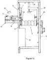
- Figure 2shows the leak detector 1 mounted to a support frame 2 with a protective housing 22 covering the testing station including a human machine interface 24.
- the other figuresshow the detail of the testing mechanisms.
- the leak detector 1has a frame 2 which in use rests on a surface (a warehouse floor or similar) to hold the remainder of the apparatus away from the ground.
- the frame 2also holds various parts of the remainder of the testing apparatus in position.
- the leak detector 1has a central conveyor 3 which in the preferred embodiment is of the linear endless belt type, aligned horizontally to convey items from one (open) end or side of the leak detector 1 to the other, opposite (open) side.
- the conveyor 3can be formed from a number of smaller sub-belts in parallel or a single wide belt.
- a sub-frame 4is pivotally connected to the frame 2 to one side of the conveyor 3.
- the sub-frame 4is connected to the frame 2 via a hinge 5 located below the level of the central conveyor 3, the sub-frame 4 extending upwards above and to the side of the conveyor 3.
- a first actuator 6is mounted on a second sub-frame (not shown) above the conveyor 3.
- the actuator 6is, in the preferred embodiment, a pneumatic cylinder with linear travel.
- the actuator 6could be a hydraulic cylinder, or any other suitable type of actuator: linear, rotary or otherwise.
- the active or moving end of the first pneumatic cylinder 6is connected to the sub-frame 4.
- the body of the first cylinder 6is connected and held rigidly in relation to the conveyor 3, via the second sub-frame. As the cylinder 6 activates, it pushes the sub-frame 4 so that the sub-frame 4 rotates outwards around the pivot point of the hinge 5 away from the conveyor 3.
- a gusset manipulation station 10is connected to the sub-frame 4, the station is connected so that it is just above and to the side of the surface of the conveyor 3.
- the gusset manipulation station 10has a number of interlocking and moving elements which are activated by actuating cylinders as described below.
- a fixed anvil 8is connected to the sub-frame 4.
- the fixed anvil 8has a horizontal upwards-facing anvil striking surface.
- a second linear actuator - flap clamp cylinder 7 -is connected to the sub-frame 4 between the body of the sub-frame 4 and the conveyor 3, above the fixed anvil 8.
- the preferred embodiment of flap clamp cylinder 7is a pneumatic cylinder, with a moving piston that has a clamp anvil 9 on the lower end, the clamp anvil 9 having a downwards-facing anvil surface complimentary to and aligned with the upwardly-facing surface of the fixed anvil 8.
- the position of the fixed anvil 8is vertically adjustable, and most preferably horizontally adjustable also (towards and away from the conveyor 3).
- the position of the flap clamp cylinder 7 and in particular the clamp anvil 9is adjustable in a complimentary manner, either by adjustment of the position of the flap clamp cylinder 7 in it's entirety, or by adjusting the stroke length to suit, so that contact is made at all positions between the flap clamp cylinder 7 and the clamp anvil 9.
- the linear pneumatic flap clamp cylinder 7could be replaced by any suitable clamping mechanism - for example by a jaw rotating towards the anvil, or a pair of jaws rotating together towards one another, or clamping elements which screw towards one another.
- a pair of mechanical fingers 11a, 11bare located one on each side of the gusset manipulation station 10.
- Each finger 11is formed from an elongate member extending towards the conveyor 3, the two fingers 11a, 11b angled away from one another (that is, if the lines of the main portion of the bodies of the fingers were extended to convergence, this would occur at a point further away from the conveyor).
- the outer end (away from the conveyor) of each finger 11a and 11bis connected to a pivoting element 12a and 12b that pivots around a substantially vertical axis so that the fingers 11a and 11b rotate in a substantially horizontal plane.
- the inner ends of the fingers 11a and 11bare angled inwards to form hook portions 13a and 13b.
- the pivoting elements 12a and 12bare a pair of meshed, interlocking gear sections or arcs connected to the sub-frame 4, the interlocking portions located between the vertical rotation axes.
- a third linear actuator 14is connected between a fixed point on the sub-frame 4, and a point on the perimeter of one of the pivoting elements 12a and 12b (i.e. at a distance from the vertical rotation axis of that pivoting element, and between the rotation axes).
- the third linear actuator 14is aligned to activate horizontally away from the conveyor 3 (in the preferred embodiment, substantially perpendicular to the conveyor 3).
- the third linear actuator 14activates, it causes the connected one of the pivoting elements 12 to rotate around the vertical rotation axis, which causes the other pivot element to also rotate in the opposite direction due to the meshed gearing. This causes the fingers 11 to rotate inwards, or towards one another.
- the fingers 11 and the hook portions 13are shaped and sized so that the inner ends arc towards one another and nearly contact each other just to the side and above the edge of the conveyor 3.
- the third linear actuatoris a pneumatic cylinder. As before, this could alternatively be a hydraulic cylinder, a rotary screw, or a similar actuating mechanism.
- the fingers and their associated elementsform another part of the mechanical gripper formed by flap clamp cylinder 7, clamp anvil 9 and anvil 8.
- the gusset manipulation station 10is mounted to the sub-frame 4 in such a manner that it can move relative to the sub-frame 4, substantially horizontally towards and away from the sub-frame 4 and conveyor 3.
- a single specimen of the product to be testedi.e. a 20kg block of vacuum packed cheese 16 in the preferred embodiment (or other similar vacuum packed product) is guided onto the belt of the central conveyor 3 at one end, and moves with the belt along and through the leak detector 1 to a point determined by a photo cell (not shown) mounted either on the frame 2, or an equally appropriate position.
- a photo cell(not shown) mounted either on the frame 2, or an equally appropriate position.
- Another similar type of sensorcould be used instead of the photo cell (for example a weight sensor placed under the belt at the appropriate position, which activates when the cheese or other product is above the sensor.
- the bagged cheese 16is placed on the belt so that the flap/seal 17 extends generally horizontally out to one side of the conveyor, on the same side as the sub-frame 2.
- the vertical position of the flap/sealis known, as each individual product item is substantially identical to the others.
- Thisallows an initial setup/location of items such as the position of the clamp anvil 9 and the fixed anvil 8.
- the block of cheese 16travels along the conveyor 3 until the photo cell detects that the bagged cheese 16 is positioned and/or aligned opposite the gusset manipulation station 10.
- Linear actuator 23may then push the bagged cheese 16 towards the gusset manipulation station 10 until the flap 17 is between the clamp anvil 9 and the fixed anvil 8.
- Linear actuator 23may extend a predetermined distance each time for packages of consistent dimensions or a further sensor may be employed to detect that the flap 17 is correctly located between the anvils.
- the first linear actuator - the flap clamp pneumatic cylinder 7 -is then activated to push the clamp anvil 9 downwards and clamp the flap 17 between the clamp anvil 9 and the fixed anvil 8.
- the second linear actuator - the bag flap stressing pneumatic cylinder 6 -further has an associated sensing means (not shown).
- the bag flap stressing cylinder 6is then activated to apply a force to the sub-frame 4 and rotate this around the pivot point of the hinge 5 and away from the block of cheese.
- the sensing meanswill start to measure the displacement of the sub-frame 4, which is indicative of a leak in the plastic packaging.
- the sensing meansis an actuator position sensor or mounted position transmitter, most preferably a linear variable differential transformer (LVDT) or similar inductive device.
- LVDTlinear variable differential transformer
- the product movementis limited towards sub-frame 4 by a fence fitted to the frame of the testing unit and providing a measurement reference for the displacement of the gripped flap.
- a clamp or holding systemcan be added to the apparatus to secure it in place during the testing sequence.
- the third linear actuator 14is activated. This causes the two mechanical fingers 11a, 11b to rotate inwards towards one another. The hook portions 13a, 13b on the ends of the fingers 11a, 11b will be inserted into the folded gussets on each side of the flap 17 of the plastic bag. This action is independent of the action of the bag flap stressing cylinder 6 and the flap clamp cylinder 7.
- the third linear actuator - pneumatic cylinder 14continues to extend to apply an outwards force to push the fingers 11a and 11b away from the conveyor 3. This causes the hook portions to snag into and manipulate the gusset, and in particular the inside of the plastic gusset seal weld, and a pulling force is applied away from the block of cheese 16. This action will indicate any weakness in the heat sealed area, which will translate to further measurable movement in bag flap stressing cylinder 6 if a leak is present.
- the preferred embodiment of the present inventionincludes an evaluator or evaluating means which receives signals relating to the sensed movement, and uses these to evaluate whether there is a leak or not.
- the leak evaluationis conducted using the sensed amount of movement from bag flap stressing cylinder 6.
- the amount of movementis compared with an acceptable or predefined profile, which is held in the memory of the evaluator.
- the results of this evaluationtags the product acceptable, or to be rejected.
- An additional suction testing methodmay also be employed.
- a linear actuator in the form of pneumatic ram 25may lower suction cup 26 down onto the top surface of the block of cheese 16. Suction may then be applied to the suction cup 26 and the pneumatic ram may be retracted with a set force. The distance travelled up by the pneumatic ram may be measured to provide an additional assessment as to whether the bag is leaking or not.
- a suction testing methodmay be used before, after or during the gusset flap testing method described above.
- the method (and associated apparatus) as outlined aboveis advantageous as outlined below: Pulling the flap/seal 17 is an effective method of detecting large leaks, and pulling in this manner puts lower stress on the packaging.
- a mechanical gripperprovides a robust and reliable means of engagement with the packaging, and does not require a flat surface for use.
- the apparatuscan therefore provide a useful alternative to an apparatus or method that uses only a suction cup.
- gusset manipulationalso acts as a useful comparator to the physical manipulation.
Landscapes
- Physics & Mathematics (AREA)
- General Physics & Mathematics (AREA)
- Examining Or Testing Airtightness (AREA)
Description
- The present invention relates to a device for detecting leaks and testing the integrity of vacuum-sealed packages. The present invention also relates to a method for detecting leaks and testing the integrity of vacuum-sealed packages. More particularly, although not exclusively, the present invention relates to an apparatus and method where film packaging is put under tension in a particular area and direction, and in a particular manner, and the result is compared to a standard profile to assess the integrity of the vacuum package.
- Vacuum packing or vacuum packaging is a method of food packaging in which all or nearly all of the air in a food package is removed prior to the package being sealed. As the amount of oxygen in the sealed package has been significantly reduced, the growth of aerobic bacteria or fungi is inhibited. The reduction of air also helps to prevent or reduce the evaporation of volatile components from the foodstuff.
- Removing air from the container extends the shelf life of foods and reduces the volume of the contents and package. This allows certain foodstuffs that would otherwise spoil quickly to be stored for longer before use. This also enables perishable foodstuffs to be economically and practically transported over longer distances than would otherwise be the case, with space requirements minimised. It is important that the seal is correctly formed before the foodstuffs are transported or stored, and it is important that the seal remains intact until knowingly broken by an end user. Once the seal is broken, bacteria or fungi within the foodstuff are exposed to atmosphere, and their growth is no longer inhibited. If the seal was not initially properly formed (and the foodstuff has remained exposed to atmosphere), or if the seal has been inadvertently broken post-forming, this can lead to inadvertent or unwanted spoilage and wastage. To avoid this, a number of methods and devices have been devised to test the integrity of seals post-packaging.
- One common testing method is to test the packages in evacuated chambers, or to submerge the packages in water. An evacuated chamber is bulky, requires maintenance and can be complex to operate. Immersion requires a water tank, and there is associated expense to build and maintain this tank, an associated complexity of operation and potential contamination of the foodstuffs.
- Another known method is to use suction cups on package film to pull the film away from the product and measure the displacement relative to a control package. One drawback to this method is that it can be difficult to achieve a good seal on the packaging as this requires a relatively flat surface area for the cup to seal onto. It is also preferred that the film or other packaging has sufficient 'give' for a useful measurement to be achievable. This can sometimes be difficult to achieve.
US3,744,210 describes a method and apparatus where testing for vacuum leaks in cheese blocks is carried out by detecting leakage of tracer gas introduced into packaging.US4,517,827 describes a method and apparatus whereby a compressive force is applied to a vacuum packed package that contains a particulate contents, and the displacement of the packaging is measured and compared to a control package to determine leak integrity.US5,531,101 describes a method and apparatus which applies tension to the surface packaging of a vacuum packed product via a rotatable roller frictionally engaged with the packaging, to determine displacement compared to a control package. The roller imparts a compressive and shear force to the packaging of a vacuum packed product to create tension and displacement across the face of the product.US3,998,091 describes a method and apparatus which tests the packaging of a vacuum-packed product for leaks by applying a rotational force to the package and measuring the deflection relative to that of a standard package with an intact seal.US2010/0122570 describes a leak detector system for a sealed food package where a portion of the packaging is deflected, and the deflection compared to the deflection characteristic of a standard, sealed package. Other leak detector systems of the prior art are disclosed inDE19622588C1 .WO93/18385A1 EP1050469A1 .- There are a number of drawbacks associated with the methods which are known in the art. Methods and apparatus which use tracer gases or water immersion are prone to contamination of the foodstuff. Methods and apparatus which apply force to the packaging can subject the packaging material to excessive stress which can result in damage. The known methods and associated apparatus can be expensive, unreliable and slow.
- It is an object of the present invention to provide a device for detecting leaks and testing the integrity of vacuum-sealed packages which goes some way to overcoming the abovementioned disadvantages or which at least provides the public or industry with a useful choice.
- It is a further object of the present invention to provide a method for detecting leaks and testing the integrity of vacuum-sealed packages which goes some way to overcoming the abovementioned disadvantages or which at least provides the public or industry with a useful choice.
- Further objects and advantages of the invention will be brought out in the following portions of the specification, wherein the detailed description is for the purpose of fully disclosing the preferred embodiment of the invention without placing limitations thereon.
- The background discussion (including any potential prior art) is not to be taken as an admission of the common general knowledge.
- In a first aspect, the invention may broadly be said to consist in a seal testing apparatus for testing the integrity of the seal in the packaging of a vacuum packed, according to
claim 1. - Preferably the mechanical gripper is a clamp adapted to close and grip each side of a flap extending from the main body of the packaging.
- Preferably the clamp has at least one moving portion which is driven by a second actuator.
- Preferably the second actuator is a pneumatic cylinder with linear travel.
- Preferably the first actuator is a linear actuator.
- Preferably the first actuator is a pneumatic cylinder.
- Preferably the sensing means is an actuator position sensor or mounted position transmitter.
- Preferably the sensing means is a linear variable differential transformer (LVDT) or similar inductive device.
- Preferably the seal testing apparatus further has a frame on which the vacuum-packed product rests in use, and the gripper is mounted on a sub-frame pivotally connected to the frame, the first actuator acting on the sub-frame to urge the gripper away from the frame.
- Preferably the seal testing apparatus further has a gusset manipulator, comprising at least one finger which is inserted into the gusset fold area to manipulate a gusset in the packaging associated with the flap.
- Preferably the gusset manipulator is a pair of fingers that pivot into and out of engagement with the gusset fold, each of the fingers having a hook portion on the inner end which is inserted into the side of the gusset fold as the fingers engage.
- Preferably the fingers are mounted on the sub-frame via vertically-aligned pivot points and are connected via intermeshing gear segments, a third linear actuator connecting between the frame and one of the gear segments to rotate the gear segment and move the fingers into engagement when activated.
- Preferably the gusset manipulator is moveably connected to the sub-frame via a fourth linear actuator which pushes the gusset manipulator away from the frame when activated.
- Preferably an endless linear belt is mounted on the frame, the package resting on and transported by the belt in operation.
- Preferably the belt transports the package from one side of the frame to the other, past the sub-frame and gusset manipulator.
- Preferably the seal testing machine further has a sensor which automatically detects when the package is aligned with the sub-frame and gusset manipulator, the evaluator controlling movement of the belt and stopping the belt when the package is correctly aligned.
- Preferably a linear actuator positions the package towards the gusset manipulator such as to facilitate testing.
- Preferably the evaluator receives input from the sensing means and assesses seal integrity by comparing actual displacement over time to a predefined acceptable profile of displacement and time.
- The acceptable profile may consist of an absolute displacement.
- Alternatively the acceptable profile may consist of displacement over a time interval.
- In a second aspect the invention may broadly be said to consist in a method of testing seal integrity in the packaging of a vacuum packed product, according to claim 11.
- Preferably in the step of comparing the monitored movement with an acceptable profile actual displacement over time is compared to a predefined acceptable profile of displacement and time.
- The step of comparing the monitored movement with an acceptable profile the acceptable profile may consist of an absolute displacement.
- Alternatively in the step of comparing the monitored movement with an acceptable profile the acceptable profile may consist of displacement over a time interval.
- Preferably after a predetermined time the mechanical grip is released and the displacement assessed.
- Preferably in the step of mechanically gripping a portion of the packaging a flap or seal is gripped.
- Preferably in the step of mechanically gripping a portion of the packaging mechanical fingers are inserted into the gusset fold area to manipulate a gusset in the packaging associated with the flap.
- Embodiments of the present invention will now be described, by way of example only, with reference to the accompanying drawings, in which:
- Figure 1a
- shows a perspective view of an embodiment of the seal testing apparatus of the present invention;
- Figure 1b
- shows a plan view of the embodiment of the seal testing apparatus of the present invention shown in
figure 1a ; - Figure 1c
- shows a view from the entry end of the embodiment of the seal testing apparatus of the present invention shown in
figures 1a andfigure 1b ; - Figure 1d
- shows a side view of the embodiment of the seal testing apparatus of the present invention shown in
figures 1a ,1b , and1c ; - Figure 2
- shows a perspective view of the seal testing apparatus of the present invention shown in
figures 1a-d mounted to a frame with a protective enclosure around the testing station; - Figure 3a
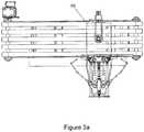
- shows a plan view of a gusset manipulation station that forms part of the seal testing apparatus of the present invention;
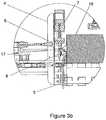
- Figure 3b
- shows a cross-sectional view along line A-A in
Figure 3a ; and - Figure 3c
- shows a vacuum packed package of cheese with a flap/seal at one end.
- The preferred embodiments of the invention are described below. The preferred embodiments are described in relation to testing the seal integrity for a generally cuboidal block of cheese weighing 20 kilograms, vacuum-packed in film packaging, the cuboidal block several times wider and longer than it is high. However, the invention may also be applied to any other suitable vacuum-packed items of different sizes with the same or similar configuration - for example a bag of ground coffee or coffee beans which also has a sealed flap - and the description should not be taken as limiting. Also, the preferred embodiment is described in relation to a vacuum-packed item where the item is sealed within a bag formed from film packaging which has a single open end, sealed during the packaging process and with a seal/flap extending from one side or end. The invention could be used with other forms of vacuum-packaging, or other configurations of packaging, for example where the seal or flap is at the top of the packet - e.g. as in a bag of ground coffee or coffee beans. If the seal flap is at the top of the bag, the testing would be carried out either with the bag lying on its side, or a modification of the preferred embodiment as described below would be used in order to test for a package with an upwardly-oriented flap.
- A
leak detector 1 is shown in the figures.Figure 2 shows theleak detector 1 mounted to asupport frame 2 with aprotective housing 22 covering the testing station including ahuman machine interface 24. The other figures show the detail of the testing mechanisms. Theleak detector 1 has aframe 2 which in use rests on a surface (a warehouse floor or similar) to hold the remainder of the apparatus away from the ground. Theframe 2 also holds various parts of the remainder of the testing apparatus in position. Theleak detector 1 has acentral conveyor 3 which in the preferred embodiment is of the linear endless belt type, aligned horizontally to convey items from one (open) end or side of theleak detector 1 to the other, opposite (open) side. As shown in the figures, theconveyor 3 can be formed from a number of smaller sub-belts in parallel or a single wide belt. - A
sub-frame 4 is pivotally connected to theframe 2 to one side of theconveyor 3. Thesub-frame 4 is connected to theframe 2 via ahinge 5 located below the level of thecentral conveyor 3, thesub-frame 4 extending upwards above and to the side of theconveyor 3. Afirst actuator 6 is mounted on a second sub-frame (not shown) above theconveyor 3. Theactuator 6 is, in the preferred embodiment, a pneumatic cylinder with linear travel. However, theactuator 6 could be a hydraulic cylinder, or any other suitable type of actuator: linear, rotary or otherwise. The active or moving end of the firstpneumatic cylinder 6 is connected to thesub-frame 4. The body of thefirst cylinder 6 is connected and held rigidly in relation to theconveyor 3, via the second sub-frame. As thecylinder 6 activates, it pushes thesub-frame 4 so that thesub-frame 4 rotates outwards around the pivot point of thehinge 5 away from theconveyor 3. - A
gusset manipulation station 10 is connected to thesub-frame 4, the station is connected so that it is just above and to the side of the surface of theconveyor 3. Thegusset manipulation station 10 has a number of interlocking and moving elements which are activated by actuating cylinders as described below. - A fixed
anvil 8 is connected to thesub-frame 4. The fixedanvil 8 has a horizontal upwards-facing anvil striking surface. A second linear actuator - flap clamp cylinder 7 - is connected to thesub-frame 4 between the body of thesub-frame 4 and theconveyor 3, above the fixedanvil 8. The preferred embodiment offlap clamp cylinder 7 is a pneumatic cylinder, with a moving piston that has aclamp anvil 9 on the lower end, theclamp anvil 9 having a downwards-facing anvil surface complimentary to and aligned with the upwardly-facing surface of the fixedanvil 8. When theflap clamp cylinder 7 activates, the downwards-facing anvil surface of theclamp anvil 9 is moved downwards to contact and press against the upwardly-facing surface of theanvil 8. These items form a mechanical gripper for a package, either by themselves or in combination with other items as described below. In the preferred embodiment, the position of the fixedanvil 8 is vertically adjustable, and most preferably horizontally adjustable also (towards and away from the conveyor 3). The position of theflap clamp cylinder 7 and in particular theclamp anvil 9 is adjustable in a complimentary manner, either by adjustment of the position of theflap clamp cylinder 7 in it's entirety, or by adjusting the stroke length to suit, so that contact is made at all positions between theflap clamp cylinder 7 and theclamp anvil 9. The linear pneumaticflap clamp cylinder 7 could be replaced by any suitable clamping mechanism - for example by a jaw rotating towards the anvil, or a pair of jaws rotating together towards one another, or clamping elements which screw towards one another. - A pair of
mechanical fingers gusset manipulation station 10. Each finger 11 is formed from an elongate member extending towards theconveyor 3, the twofingers finger pivoting element fingers fingers hook portions elements sub-frame 4, the interlocking portions located between the vertical rotation axes. A thirdlinear actuator 14 is connected between a fixed point on thesub-frame 4, and a point on the perimeter of one of thepivoting elements linear actuator 14 is aligned to activate horizontally away from the conveyor 3 (in the preferred embodiment, substantially perpendicular to the conveyor 3). As the thirdlinear actuator 14 activates, it causes the connected one of the pivoting elements 12 to rotate around the vertical rotation axis, which causes the other pivot element to also rotate in the opposite direction due to the meshed gearing. This causes the fingers 11 to rotate inwards, or towards one another. The fingers 11 and the hook portions 13 are shaped and sized so that the inner ends arc towards one another and nearly contact each other just to the side and above the edge of theconveyor 3. In the preferred embodiment, the third linear actuator is a pneumatic cylinder. As before, this could alternatively be a hydraulic cylinder, a rotary screw, or a similar actuating mechanism. The fingers and their associated elements form another part of the mechanical gripper formed byflap clamp cylinder 7, clampanvil 9 andanvil 8. - In the preferred embodiment, the
gusset manipulation station 10 is mounted to thesub-frame 4 in such a manner that it can move relative to thesub-frame 4, substantially horizontally towards and away from thesub-frame 4 andconveyor 3. - Operation of the apparatus will now be described with reference to the structural elements described above, and further structural description as necessary.
- A single specimen of the product to be tested - i.e. a 20kg block of vacuum packed
cheese 16 in the preferred embodiment (or other similar vacuum packed product) is guided onto the belt of thecentral conveyor 3 at one end, and moves with the belt along and through theleak detector 1 to a point determined by a photo cell (not shown) mounted either on theframe 2, or an equally appropriate position. Another similar type of sensor could be used instead of the photo cell (for example a weight sensor placed under the belt at the appropriate position, which activates when the cheese or other product is above the sensor. The baggedcheese 16 is placed on the belt so that the flap/seal 17 extends generally horizontally out to one side of the conveyor, on the same side as thesub-frame 2. As the preferred embodiment of the apparatus will be used to test multiple specimens of identical size and packaging, the vertical position of the flap/seal is known, as each individual product item is substantially identical to the others. This allows an initial setup/location of items such as the position of theclamp anvil 9 and the fixedanvil 8. The block ofcheese 16 travels along theconveyor 3 until the photo cell detects that the baggedcheese 16 is positioned and/or aligned opposite thegusset manipulation station 10.Linear actuator 23 may then push the baggedcheese 16 towards thegusset manipulation station 10 until theflap 17 is between theclamp anvil 9 and the fixedanvil 8.Linear actuator 23 may extend a predetermined distance each time for packages of consistent dimensions or a further sensor may be employed to detect that theflap 17 is correctly located between the anvils. - The first linear actuator - the flap clamp pneumatic cylinder 7 - is then activated to push the
clamp anvil 9 downwards and clamp theflap 17 between theclamp anvil 9 and the fixedanvil 8. - The second linear actuator - the bag flap stressing pneumatic cylinder 6 - further has an associated sensing means (not shown). Once the
flap 17 is clamped, the bagflap stressing cylinder 6 is then activated to apply a force to thesub-frame 4 and rotate this around the pivot point of thehinge 5 and away from the block of cheese. As theflap 17 is gripped between theclamp anvil 9 and the fixedanvil 8 it will pull away from and to the side of the block ofcheese 16. The sensing means will start to measure the displacement of thesub-frame 4, which is indicative of a leak in the plastic packaging. In the preferred embodiment, the sensing means is an actuator position sensor or mounted position transmitter, most preferably a linear variable differential transformer (LVDT) or similar inductive device. The product movement is limited towardssub-frame 4 by a fence fitted to the frame of the testing unit and providing a measurement reference for the displacement of the gripped flap. For lighter products a clamp or holding system can be added to the apparatus to secure it in place during the testing sequence.
At the same time as the bagflap stressing cylinder 6 is activated, the thirdlinear actuator 14 is activated. This causes the twomechanical fingers hook portions fingers flap 17 of the plastic bag. This action is independent of the action of the bagflap stressing cylinder 6 and theflap clamp cylinder 7. - Once the
fingers pneumatic cylinder 14 continues to extend to apply an outwards force to push thefingers conveyor 3. This causes the hook portions to snag into and manipulate the gusset, and in particular the inside of the plastic gusset seal weld, and a pulling force is applied away from the block ofcheese 16. This action will indicate any weakness in the heat sealed area, which will translate to further measurable movement in bagflap stressing cylinder 6 if a leak is present. The preferred embodiment of the present invention includes an evaluator or evaluating means which receives signals relating to the sensed movement, and uses these to evaluate whether there is a leak or not. In the preferred embodiment, the leak evaluation is conducted using the sensed amount of movement from bagflap stressing cylinder 6. The amount of movement is compared with an acceptable or predefined profile, which is held in the memory of the evaluator. The results of this evaluation tags the product acceptable, or to be rejected. - An additional suction testing method may also be employed. A linear actuator in the form of
pneumatic ram 25 may lowersuction cup 26 down onto the top surface of the block ofcheese 16. Suction may then be applied to thesuction cup 26 and the pneumatic ram may be retracted with a set force. The distance travelled up by the pneumatic ram may be measured to provide an additional assessment as to whether the bag is leaking or not. A suction testing method may be used before, after or during the gusset flap testing method described above. - After a predetermined time all the actuators -
first cylinder 6,flap clamp cylinder 7,third cylinder 14 and fourth cylinder(s) 15 - will return to their resting position. This releases the block ofcheese 16. Once the cylinders reach their initial or resting position, movement of theconveyor 3 resumes. - The method (and associated apparatus) as outlined above is advantageous as outlined below:
Pulling the flap/seal 17 is an effective method of detecting large leaks, and pulling in this manner puts lower stress on the packaging. - Testing the gusset by manipulating and pulling from the inside (using the fingers) allows good detection of slow leaks, and requires the application of minimal force on the packaging.
- Using a mechanical gripper provides a robust and reliable means of engagement with the packaging, and does not require a flat surface for use. The apparatus can therefore provide a useful alternative to an apparatus or method that uses only a suction cup.
- Using a method where the flap/seal is pulled and also the gusset is manipulated or pulled from inside the folds provides both a primary and secondary method of determining leaks (the seal/flap pull and the gusset manipulation, respectively). The gusset manipulation also acts as a useful comparator to the physical manipulation.
- While the present invention has been illustrated by the description of the embodiments thereof, and while the embodiments have been described in detail, it is not the intention of the applicant to restrict or in any way limit the scope of the appended claims to such detail. Additional advantages and modifications will readily appear to those skilled in the art. Therefore, the invention in its broader aspects is not limited to the specific details, representative apparatus and method, and illustrative examples shown and described.
Claims (15)
- A seal testing apparatus (1) for testing the integrity of the seal in the packaging of a vacuum packed product (16), comprising:a mechanical gripper (8, 9) for gripping a portion of the packaging (17);a first actuator (6) configured to pull the gripped portion away from the product;a sensor for monitoring the movement of the gripped portion relative to the vacuum packed product (16), and;an evaluator that compares the sensed movement of the gripped portion with an acceptable profile and accepts or rejects the product based on the comparison.
- A seal testing apparatus as claimed in claim 1 wherein the mechanical gripper is a clamp adapted to close and grip each side of a flap extending from the main body of the packaging.
- A seal testing apparatus as claimed in claim 1 or claim 2 wherein the sensor is an actuator position sensor or mounted position transmitter.
- A seal testing apparatus as claimed in any one of claims 1 to 3 wherein the seal testing apparatus further has a frame on which the vacuum-packed product rests in use, the gripper is mounted on a sub-frame pivotally connected to the frame, the first actuator acting on the sub-frame to pull the closed gripper away from the product.
- A seal testing apparatus as claimed in any one of claims 1 to 4 wherein the seal testing apparatus further has a gusset manipulator, comprising at least one finger which is inserted into the gusset fold area to manipulate a gusset in the packaging associated with the flap.
- A seal testing apparatus as claimed in claim 5 wherein the gusset manipulator is a pair of fingers that pivot into and out of engagement with the gusset fold, each of the fingers having a hook portion on the inner end which is inserted into the side of the gusset fold as the fingers engage.
- A seal testing machine as claimed in any one of claims 4 to 6 wherein an endless linear belt is mounted on the frame, the package resting on and transported by the belt in operation, the belt transporting the package from one side of the frame to the other, past the sub-frame and gusset manipulator.
- A seal testing machine as claimed in any one of claims 1 to 7 wherein the evaluator receives input from the sensor and assesses seal integrity by comparing actual displacement over time to a predefined acceptable profile of displacement and time.
- A seal testing machine as claimed in claim 8 wherein the acceptable profile consists of an absolute displacement.
- A seal testing machine as claimed in claim 8 wherein the acceptable profile consists of displacement over a time interval.
- A method of testing seal integrity in the packaging of a vacuum packed product comprising the steps of:mechanically gripping a portion of the packaging;applying a force to pull the gripped portion in a direction away from the product;monitoring the movement of the gripped portion relative to the vacuum packed product;comparing the monitored movement with an acceptable profile; andaccepting or rejecting the product based on the comparison.
- A method of testing seal integrity as claimed in claim 11 wherein in the step of comparing the monitored movement with an acceptable profile actual displacement over time is compared to a predefined acceptable profile of displacement and time.
- A method of testing seal integrity as claimed in claim 11 or claim 12 wherein in the step of comparing the monitored movement with an acceptable profile the acceptable profile consists of an absolute displacement.
- A method of testing seal integrity as claimed in claim 11 or claim 12 wherein in the step of comparing the monitored movement with an acceptable profile the acceptable profile consists of displacement over a time interval.
- A method of testing seal integrity as claimed in any one of claims 11 to 14 wherein in the step of mechanically gripping a portion of the packaging mechanical fingers are inserted into the gusset fold area to manipulate a gusset in the packaging associated with the flap.
Applications Claiming Priority (2)
| Application Number | Priority Date | Filing Date | Title |
|---|---|---|---|
| NZ61832913 | 2013-11-28 | ||
| PCT/NZ2014/000236WO2015080601A1 (en) | 2013-11-28 | 2014-11-27 | A leak detector and package integrity testing mechanism and testing method for vacuum-sealed packages |
Publications (2)
| Publication Number | Publication Date |
|---|---|
| EP3074745A1 EP3074745A1 (en) | 2016-10-05 |
| EP3074745B1true EP3074745B1 (en) | 2019-11-13 |
Family
ID=52350263
Family Applications (1)
| Application Number | Title | Priority Date | Filing Date |
|---|---|---|---|
| EP14827561.3ANot-in-forceEP3074745B1 (en) | 2013-11-28 | 2014-11-27 | A leak detector and package integrity testing mechanism and testing method for vacuum-sealed packages |
Country Status (4)
| Country | Link |
|---|---|
| US (1) | US20170160164A1 (en) |
| EP (1) | EP3074745B1 (en) |
| AU (2) | AU2014355230A1 (en) |
| WO (1) | WO2015080601A1 (en) |
Families Citing this family (5)
| Publication number | Priority date | Publication date | Assignee | Title |
|---|---|---|---|---|
| DE102018202451B4 (en)* | 2018-02-19 | 2023-01-12 | Vitesco Technologies Germany Gmbh | Pouch cell tightness measuring arrangement and method for measuring a tightness of pouch cells |
| EP3839470B1 (en) | 2019-12-16 | 2025-01-15 | Elopak ASA | Method and apparatus for testing paperboard-based containers |
| CN115090558B (en)* | 2022-07-30 | 2023-03-03 | 东莞市群立自动化科技有限公司 | Lithium battery leakage detection equipment and detection method |
| CN116793598B (en)* | 2023-07-19 | 2024-05-03 | 重庆南瑞博瑞变压器有限公司 | Pressure maintaining sealing detection device for oil immersed transformer |
| CN120369235A (en)* | 2025-06-26 | 2025-07-25 | 崇义县勤慧农业发展有限公司 | Automatic detection device for air tightness of bagged vacuum food |
Family Cites Families (10)
| Publication number | Priority date | Publication date | Assignee | Title |
|---|---|---|---|---|
| US2374140A (en)* | 1943-07-09 | 1945-04-17 | Robert N Shoner | Seal leakage detector for canned goods |
| US3744210A (en) | 1971-06-28 | 1973-07-10 | Standard Packaging Corp | Packaging machine and method |
| US3877302A (en)* | 1973-12-06 | 1975-04-15 | Us Army | Method for determining tightness of film shrunk over a container or an assembly of containers |
| US3998091A (en)* | 1975-06-23 | 1976-12-21 | Paquette Michael W | Test apparatus for determining quality of packaging for vacuum packaged products |
| US4517827A (en) | 1983-03-24 | 1985-05-21 | General Foods Incorporated | Apparatus and method for testing for leakages in hermetically-sealed packages |
| GB9205011D0 (en)* | 1992-03-07 | 1992-04-22 | Fenlon Christopher | Sealed package integrity testing machine |
| DE19622588C1 (en)* | 1996-06-05 | 1998-01-02 | Koeger Heinz | Container seal integrity testing device |
| EP1050469B1 (en)* | 1999-04-07 | 2003-03-19 | Ishida Co., Ltd. | Automatic package inspecting system |
| US20100122570A1 (en) | 2008-11-14 | 2010-05-20 | Kraft Foods Global Brands Llc | Method and apparatus for detecting sealing of food packages |
| DE202011107446U1 (en)* | 2011-11-04 | 2013-02-06 | Eckhard Polman | Apparatus for vacuum-based leak testing of packages supplied in a continuous packaging stream |
- 2014
- 2014-11-27AUAU2014355230Apatent/AU2014355230A1/ennot_activeAbandoned
- 2014-11-27USUS15/039,376patent/US20170160164A1/ennot_activeAbandoned
- 2014-11-27WOPCT/NZ2014/000236patent/WO2015080601A1/enactiveApplication Filing
- 2014-11-27EPEP14827561.3Apatent/EP3074745B1/ennot_activeNot-in-force
- 2019
- 2019-08-02AUAU2019210663Apatent/AU2019210663A1/ennot_activeAbandoned
Non-Patent Citations (1)
| Title |
|---|
| None* |
Also Published As
| Publication number | Publication date |
|---|---|
| AU2019210663A1 (en) | 2019-08-22 |
| WO2015080601A1 (en) | 2015-06-04 |
| EP3074745A1 (en) | 2016-10-05 |
| AU2014355230A1 (en) | 2016-07-07 |
| US20170160164A1 (en) | 2017-06-08 |
Similar Documents
| Publication | Publication Date | Title |
|---|---|---|
| AU2019210663A1 (en) | A leak detector and package integrity testing mechanism and testing method for vacuum-sealed packages | |
| EP3405398B1 (en) | Method of testing the tightness of a completed package | |
| US5111684A (en) | Method and apparatus for leak testing packages | |
| AU2009251801B2 (en) | Method for positioning a loaded bag in a vacuum chamber | |
| US3591944A (en) | Method and apparatus for detection of leaks in seals of packages | |
| ES2883262T3 (en) | Procedure and device for checking objects supplied continuously | |
| JP2012007931A (en) | Seal check device of bag-packaged product and seal check method | |
| US3708949A (en) | Method and apparatus for detection of leaks in seals of packages | |
| US5507177A (en) | Method and apparatus for testing the tightness of foil bags | |
| JPH0658281B2 (en) | Method and device for inspecting sealability of closed container filled with filling material | |
| JP6942152B2 (en) | Package inspection system | |
| US20240077394A1 (en) | Apparatus, plant and method for inspecting flexible packages | |
| JP6348294B2 (en) | Tube container inspection equipment | |
| AU2009233618A1 (en) | Method and apparatus for detecting sealing of food packages | |
| JP4072455B2 (en) | Leakage inspection method and apparatus for package seal part | |
| CN115465501B (en) | Packaging device for quick-frozen food and packaging method thereof | |
| US9056691B2 (en) | Bag deflation devices and methods for deflating bags | |
| JP2005009931A (en) | Seal defect inspection device | |
| JP4008869B2 (en) | Method and apparatus for inspecting leakage of package seal part | |
| WO2002073151A1 (en) | Production line leak testing | |
| JP2000121487A (en) | Leak inspection method for empty cans, etc. | |
| JP7010912B2 (en) | Package inspection system | |
| JP2000318716A (en) | Bag processing method and apparatus in bagging machine | |
| CN113237606A (en) | Peppery strip packing gas leakage oil leak testing equipment | |
| JP2015182795A (en) | Vacuum state inspection method and device for vacuumized package |
Legal Events
| Date | Code | Title | Description |
|---|---|---|---|
| PUAI | Public reference made under article 153(3) epc to a published international application that has entered the european phase | Free format text:ORIGINAL CODE: 0009012 | |
| 17P | Request for examination filed | Effective date:20160620 | |
| AK | Designated contracting states | Kind code of ref document:A1 Designated state(s):AL AT BE BG CH CY CZ DE DK EE ES FI FR GB GR HR HU IE IS IT LI LT LU LV MC MK MT NL NO PL PT RO RS SE SI SK SM TR | |
| AX | Request for extension of the european patent | Extension state:BA ME | |
| DAX | Request for extension of the european patent (deleted) | ||
| GRAP | Despatch of communication of intention to grant a patent | Free format text:ORIGINAL CODE: EPIDOSNIGR1 | |
| STAA | Information on the status of an ep patent application or granted ep patent | Free format text:STATUS: GRANT OF PATENT IS INTENDED | |
| INTG | Intention to grant announced | Effective date:20190607 | |
| GRAS | Grant fee paid | Free format text:ORIGINAL CODE: EPIDOSNIGR3 | |
| GRAA | (expected) grant | Free format text:ORIGINAL CODE: 0009210 | |
| STAA | Information on the status of an ep patent application or granted ep patent | Free format text:STATUS: THE PATENT HAS BEEN GRANTED | |
| AK | Designated contracting states | Kind code of ref document:B1 Designated state(s):AL AT BE BG CH CY CZ DE DK EE ES FI FR GB GR HR HU IE IS IT LI LT LU LV MC MK MT NL NO PL PT RO RS SE SI SK SM TR | |
| REG | Reference to a national code | Ref country code:CH Ref legal event code:EP Ref country code:AT Ref legal event code:REF Ref document number:1202167 Country of ref document:AT Kind code of ref document:T Effective date:20191115 | |
| REG | Reference to a national code | Ref country code:DE Ref legal event code:R096 Ref document number:602014056878 Country of ref document:DE | |
| REG | Reference to a national code | Ref country code:IE Ref legal event code:FG4D | |
| REG | Reference to a national code | Ref country code:NL Ref legal event code:MP Effective date:20191113 | |
| REG | Reference to a national code | Ref country code:LT Ref legal event code:MG4D | |
| PG25 | Lapsed in a contracting state [announced via postgrant information from national office to epo] | Ref country code:PL Free format text:LAPSE BECAUSE OF FAILURE TO SUBMIT A TRANSLATION OF THE DESCRIPTION OR TO PAY THE FEE WITHIN THE PRESCRIBED TIME-LIMIT Effective date:20191113 Ref country code:LT Free format text:LAPSE BECAUSE OF FAILURE TO SUBMIT A TRANSLATION OF THE DESCRIPTION OR TO PAY THE FEE WITHIN THE PRESCRIBED TIME-LIMIT Effective date:20191113 Ref country code:SE Free format text:LAPSE BECAUSE OF FAILURE TO SUBMIT A TRANSLATION OF THE DESCRIPTION OR TO PAY THE FEE WITHIN THE PRESCRIBED TIME-LIMIT Effective date:20191113 Ref country code:NL Free format text:LAPSE BECAUSE OF FAILURE TO SUBMIT A TRANSLATION OF THE DESCRIPTION OR TO PAY THE FEE WITHIN THE PRESCRIBED TIME-LIMIT Effective date:20191113 Ref country code:BG Free format text:LAPSE BECAUSE OF FAILURE TO SUBMIT A TRANSLATION OF THE DESCRIPTION OR TO PAY THE FEE WITHIN THE PRESCRIBED TIME-LIMIT Effective date:20200213 Ref country code:FI Free format text:LAPSE BECAUSE OF FAILURE TO SUBMIT A TRANSLATION OF THE DESCRIPTION OR TO PAY THE FEE WITHIN THE PRESCRIBED TIME-LIMIT Effective date:20191113 Ref country code:LV Free format text:LAPSE BECAUSE OF FAILURE TO SUBMIT A TRANSLATION OF THE DESCRIPTION OR TO PAY THE FEE WITHIN THE PRESCRIBED TIME-LIMIT Effective date:20191113 Ref country code:GR Free format text:LAPSE BECAUSE OF FAILURE TO SUBMIT A TRANSLATION OF THE DESCRIPTION OR TO PAY THE FEE WITHIN THE PRESCRIBED TIME-LIMIT Effective date:20200214 Ref country code:PT Free format text:LAPSE BECAUSE OF FAILURE TO SUBMIT A TRANSLATION OF THE DESCRIPTION OR TO PAY THE FEE WITHIN THE PRESCRIBED TIME-LIMIT Effective date:20200313 Ref country code:NO Free format text:LAPSE BECAUSE OF FAILURE TO SUBMIT A TRANSLATION OF THE DESCRIPTION OR TO PAY THE FEE WITHIN THE PRESCRIBED TIME-LIMIT Effective date:20200213 | |
| PG25 | Lapsed in a contracting state [announced via postgrant information from national office to epo] | Ref country code:RS Free format text:LAPSE BECAUSE OF FAILURE TO SUBMIT A TRANSLATION OF THE DESCRIPTION OR TO PAY THE FEE WITHIN THE PRESCRIBED TIME-LIMIT Effective date:20191113 Ref country code:HR Free format text:LAPSE BECAUSE OF FAILURE TO SUBMIT A TRANSLATION OF THE DESCRIPTION OR TO PAY THE FEE WITHIN THE PRESCRIBED TIME-LIMIT Effective date:20191113 Ref country code:IS Free format text:LAPSE BECAUSE OF FAILURE TO SUBMIT A TRANSLATION OF THE DESCRIPTION OR TO PAY THE FEE WITHIN THE PRESCRIBED TIME-LIMIT Effective date:20200313 | |
| REG | Reference to a national code | Ref country code:DE Ref legal event code:R119 Ref document number:602014056878 Country of ref document:DE | |
| PG25 | Lapsed in a contracting state [announced via postgrant information from national office to epo] | Ref country code:AL Free format text:LAPSE BECAUSE OF FAILURE TO SUBMIT A TRANSLATION OF THE DESCRIPTION OR TO PAY THE FEE WITHIN THE PRESCRIBED TIME-LIMIT Effective date:20191113 | |
| REG | Reference to a national code | Ref country code:CH Ref legal event code:PL | |
| PG25 | Lapsed in a contracting state [announced via postgrant information from national office to epo] | Ref country code:LU Free format text:LAPSE BECAUSE OF NON-PAYMENT OF DUE FEES Effective date:20191127 Ref country code:CZ Free format text:LAPSE BECAUSE OF FAILURE TO SUBMIT A TRANSLATION OF THE DESCRIPTION OR TO PAY THE FEE WITHIN THE PRESCRIBED TIME-LIMIT Effective date:20191113 Ref country code:LI Free format text:LAPSE BECAUSE OF NON-PAYMENT OF DUE FEES Effective date:20191130 Ref country code:RO Free format text:LAPSE BECAUSE OF FAILURE TO SUBMIT A TRANSLATION OF THE DESCRIPTION OR TO PAY THE FEE WITHIN THE PRESCRIBED TIME-LIMIT Effective date:20191113 Ref country code:ES Free format text:LAPSE BECAUSE OF FAILURE TO SUBMIT A TRANSLATION OF THE DESCRIPTION OR TO PAY THE FEE WITHIN THE PRESCRIBED TIME-LIMIT Effective date:20191113 Ref country code:EE Free format text:LAPSE BECAUSE OF FAILURE TO SUBMIT A TRANSLATION OF THE DESCRIPTION OR TO PAY THE FEE WITHIN THE PRESCRIBED TIME-LIMIT Effective date:20191113 Ref country code:CH Free format text:LAPSE BECAUSE OF NON-PAYMENT OF DUE FEES Effective date:20191130 Ref country code:DK Free format text:LAPSE BECAUSE OF FAILURE TO SUBMIT A TRANSLATION OF THE DESCRIPTION OR TO PAY THE FEE WITHIN THE PRESCRIBED TIME-LIMIT Effective date:20191113 | |
| REG | Reference to a national code | Ref country code:AT Ref legal event code:MK05 Ref document number:1202167 Country of ref document:AT Kind code of ref document:T Effective date:20191113 | |
| REG | Reference to a national code | Ref country code:BE Ref legal event code:MM Effective date:20191130 | |
| PG25 | Lapsed in a contracting state [announced via postgrant information from national office to epo] | Ref country code:SK Free format text:LAPSE BECAUSE OF FAILURE TO SUBMIT A TRANSLATION OF THE DESCRIPTION OR TO PAY THE FEE WITHIN THE PRESCRIBED TIME-LIMIT Effective date:20191113 Ref country code:MC Free format text:LAPSE BECAUSE OF FAILURE TO SUBMIT A TRANSLATION OF THE DESCRIPTION OR TO PAY THE FEE WITHIN THE PRESCRIBED TIME-LIMIT Effective date:20191113 Ref country code:SM Free format text:LAPSE BECAUSE OF FAILURE TO SUBMIT A TRANSLATION OF THE DESCRIPTION OR TO PAY THE FEE WITHIN THE PRESCRIBED TIME-LIMIT Effective date:20191113 | |
| PLBE | No opposition filed within time limit | Free format text:ORIGINAL CODE: 0009261 | |
| STAA | Information on the status of an ep patent application or granted ep patent | Free format text:STATUS: NO OPPOSITION FILED WITHIN TIME LIMIT | |
| 26N | No opposition filed | Effective date:20200814 | |
| GBPC | Gb: european patent ceased through non-payment of renewal fee | Effective date:20200213 | |
| PG25 | Lapsed in a contracting state [announced via postgrant information from national office to epo] | Ref country code:IE Free format text:LAPSE BECAUSE OF NON-PAYMENT OF DUE FEES Effective date:20191127 Ref country code:FR Free format text:LAPSE BECAUSE OF NON-PAYMENT OF DUE FEES Effective date:20200113 Ref country code:DE Free format text:LAPSE BECAUSE OF NON-PAYMENT OF DUE FEES Effective date:20200603 | |
| PG25 | Lapsed in a contracting state [announced via postgrant information from national office to epo] | Ref country code:AT Free format text:LAPSE BECAUSE OF FAILURE TO SUBMIT A TRANSLATION OF THE DESCRIPTION OR TO PAY THE FEE WITHIN THE PRESCRIBED TIME-LIMIT Effective date:20191113 Ref country code:SI Free format text:LAPSE BECAUSE OF FAILURE TO SUBMIT A TRANSLATION OF THE DESCRIPTION OR TO PAY THE FEE WITHIN THE PRESCRIBED TIME-LIMIT Effective date:20191113 Ref country code:BE Free format text:LAPSE BECAUSE OF NON-PAYMENT OF DUE FEES Effective date:20191130 | |
| PG25 | Lapsed in a contracting state [announced via postgrant information from national office to epo] | Ref country code:IT Free format text:LAPSE BECAUSE OF FAILURE TO SUBMIT A TRANSLATION OF THE DESCRIPTION OR TO PAY THE FEE WITHIN THE PRESCRIBED TIME-LIMIT Effective date:20191113 Ref country code:GB Free format text:LAPSE BECAUSE OF NON-PAYMENT OF DUE FEES Effective date:20200213 | |
| PG25 | Lapsed in a contracting state [announced via postgrant information from national office to epo] | Ref country code:CY Free format text:LAPSE BECAUSE OF FAILURE TO SUBMIT A TRANSLATION OF THE DESCRIPTION OR TO PAY THE FEE WITHIN THE PRESCRIBED TIME-LIMIT Effective date:20191113 | |
| PG25 | Lapsed in a contracting state [announced via postgrant information from national office to epo] | Ref country code:MT Free format text:LAPSE BECAUSE OF FAILURE TO SUBMIT A TRANSLATION OF THE DESCRIPTION OR TO PAY THE FEE WITHIN THE PRESCRIBED TIME-LIMIT Effective date:20191113 Ref country code:HU Free format text:LAPSE BECAUSE OF FAILURE TO SUBMIT A TRANSLATION OF THE DESCRIPTION OR TO PAY THE FEE WITHIN THE PRESCRIBED TIME-LIMIT; INVALID AB INITIO Effective date:20141127 | |
| PG25 | Lapsed in a contracting state [announced via postgrant information from national office to epo] | Ref country code:TR Free format text:LAPSE BECAUSE OF FAILURE TO SUBMIT A TRANSLATION OF THE DESCRIPTION OR TO PAY THE FEE WITHIN THE PRESCRIBED TIME-LIMIT Effective date:20191113 | |
| PG25 | Lapsed in a contracting state [announced via postgrant information from national office to epo] | Ref country code:MK Free format text:LAPSE BECAUSE OF FAILURE TO SUBMIT A TRANSLATION OF THE DESCRIPTION OR TO PAY THE FEE WITHIN THE PRESCRIBED TIME-LIMIT Effective date:20191113 |