EP3074246B1 - Tyre comprising a defect-masking pattern on a sidewall - Google Patents
Tyre comprising a defect-masking pattern on a sidewallDownload PDFInfo
- Publication number
- EP3074246B1 EP3074246B1EP14803113.1AEP14803113AEP3074246B1EP 3074246 B1EP3074246 B1EP 3074246B1EP 14803113 AEP14803113 AEP 14803113AEP 3074246 B1EP3074246 B1EP 3074246B1
- Authority
- EP
- European Patent Office
- Prior art keywords
- pattern
- sidewall
- elements
- tire
- hollow
- Prior art date
- Legal status (The legal status is an assumption and is not a legal conclusion. Google has not performed a legal analysis and makes no representation as to the accuracy of the status listed.)
- Active
Links
- 239000000463materialSubstances0.000claimsdescription3
- 230000003746surface roughnessEffects0.000claimsdescription3
- 239000000203mixtureSubstances0.000claims1
- 230000007547defectEffects0.000description6
- 238000004519manufacturing processMethods0.000description4
- 239000011324beadSubstances0.000description3
- 230000031700light absorptionEffects0.000description3
- 230000000007visual effectEffects0.000description3
- 238000010521absorption reactionMethods0.000description1
- 230000001627detrimental effectEffects0.000description1
- 239000006185dispersionSubstances0.000description1
- 239000012530fluidSubstances0.000description1
- 238000005304joiningMethods0.000description1
- 238000003754machiningMethods0.000description1
- 230000000873masking effectEffects0.000description1
- 238000012986modificationMethods0.000description1
- 230000004048modificationEffects0.000description1
- 238000000465mouldingMethods0.000description1
- 238000005096rolling processMethods0.000description1
- 238000007789sealingMethods0.000description1
Images


Classifications
- B—PERFORMING OPERATIONS; TRANSPORTING
- B60—VEHICLES IN GENERAL
- B60C—VEHICLE TYRES; TYRE INFLATION; TYRE CHANGING; CONNECTING VALVES TO INFLATABLE ELASTIC BODIES IN GENERAL; DEVICES OR ARRANGEMENTS RELATED TO TYRES
- B60C13/00—Tyre sidewalls; Protecting, decorating, marking, or the like, thereof
- B60C13/001—Decorating, marking or the like
- B—PERFORMING OPERATIONS; TRANSPORTING
- B60—VEHICLES IN GENERAL
- B60C—VEHICLE TYRES; TYRE INFLATION; TYRE CHANGING; CONNECTING VALVES TO INFLATABLE ELASTIC BODIES IN GENERAL; DEVICES OR ARRANGEMENTS RELATED TO TYRES
- B60C13/00—Tyre sidewalls; Protecting, decorating, marking, or the like, thereof
- B60C13/02—Arrangement of grooves or ribs
Definitions
- the present inventionrelates to a rubber tire for a motor vehicle comprising a sidewall and a pattern formed on this sidewall.
- a tirecomprises, in known manner, an internal carcass, a tread, a fastening bead with a rim, a sidewall, and an internal sealing element.
- the inner carcassis composed of at least one carcass ply of rubber-coated threads.
- this carcass plyis cut and assembled on a drum. This sheet being able to make several turns around this drum, there is thus a plurality of layers formed from the same carcass ply. Now, it is possible that during the setting up of the sheet, the end of this sheet does not coincide exactly with the beginning of this sheet on the drum, so that there is a surplus of sheet in the assembly. This superposition locally creates an extra thickness on the raw blank of the tire.
- this extra thicknessappears hollow at the sidewall of the tire.
- this hollowis particularly visible on the tire, especially under certain lighting conditions, which may constitute a reason for non-purchase by a consumer even though this defect is not detrimental to safety.
- moire patternsare described. These moire patterns are patterns interference including including streaks. Thus, these moire patterns create interference when the light is reflected by the sidewall of the tire. The differences in light reflection that existed between the hilly / hollow zone and the rest of the flank surface are thus no longer visible to the naked eye.
- WO2012 / 066717discloses a rubber tire comprising a flank and a pattern formed in this flank.
- the patterncomprises a plurality of hollow elements, each hollow element having the shape of a sphere portion.
- the present inventionaims to hide this flank deformation defect in a simpler way, and this for a large majority of observation angle of a consumer.
- tread of a tiremeans a quantity of rubber material delimited by lateral surfaces and by two main surfaces, one inside and one outside, said outside surface being intended to come into contact with a roadway when the tire is rolling.
- bearing of a tiremeans a portion of the tire intended to sit on a wheel rim.
- sidewall of a tireis meant a side surface of the tire disposed between the tread of the tire and a bead of the tire.
- pattern formed on a sidewallis meant a flank portion having homogeneous surface-state characteristics different from the rest of the sidewall. This reason can deliver technical and legal information, and secondly allow consumers to distinguish the origin of the product.
- average sidewall surfaceis meant the extension of the surface of the sidewall above the pattern formed on the sidewall.
- the inventionprovides a tire made of rubber material comprising a sidewall and a pattern formed in this sidewall. This flank extends along a medium surface.
- the patterncomprises a plurality of hollow elements, these recessed elements having the shape of a sphere portion. These recessed elements are interconnected at connection areas, these connection areas extending below the average surface of the sidewall. Sectional view, all or part of the hollow elements has an angular opening less than or equal to 70 °.
- the architecture of the patternavoids too much absorption of light by the texture of the sidewall of the tire.
- the light rays coming from the same light source which illuminate the sidewall of the tireare thus substantially deviated in the same manner on the pattern, both at the level of the pattern covering the deformed part of the sidewall and at the level of the pattern covering the sidewall where there is no deformation.
- connection areasare below the average surface of the sidewall, they are better protected against friction phenomena, for example from sidewalk gratings. This is particularly true when the patterns are small in size, the friction forces then being absorbed by the flank edges surrounding the pattern.
- the chosen angular aperturemakes it possible to obtain a better reflection surface for the light.
- the patternthus appears more clearly on the sidewall of the tire.
- the tiremay further comprise one or more additional characteristics among the following:
- the density of hollow elements in the patternis greater than or equal to 0.2 recessed elements per mm 2 . This gives the pattern a more uniform appearance vis-à-vis an observer.
- Sectional view, all or part of the hollow elementshas an angular opening less than or equal to 70 °. This provides a better reflection surface for the light. The pattern thus appears more clearly on the sidewall of the tire.
- the recessed elementsare aligned with each other in the pattern.
- the limits of the patternare thus better controlled.
- All or part of the hollow elementshas a surface roughness of parameter Ra less than 30 microns. This makes it possible to obtain a surface close to a polished surface and thus to limit the dispersion of the light.
- the recessed elementshave a radius R and these hollow elements are interconnected at connection areas, these connection areas being curved and having a connecting radius r, such that r ⁇ R / 3.
- the figure 1illustrates the sidewall 3 of the tire 1, said sidewall 3 comprising a pattern 5.
- the pattern 5comprises a plurality of hollow elements 7, also called concave elements 7.
- the pattern 5extends over all or part of the surface of the sidewall 3 and in particular on the part comprising the sidewall deformation 8 created by the overlap The pattern 5 thus covers the entire undulation / hollow 8.
- the figure 2shows an enlarged perspective view of part of the pattern 5 of the figure 1 .
- the recessed elements 7all have the same shape and the pattern 5 comprises a repetition of this same shape.
- the shapeis an open surface.
- the hollow elements 7are aligned with each other in the pattern 5. This allows to delimit the pattern 5.
- Each hollow element 7has the particular property of returning a quantity of light which remains constant, even when the pattern is inclined at a small angle with respect to a corresponding original position in the example at the position on the side without deformation.
- the inclination of the angleis less than 5 °, which corresponds to the inclination of the recess created by the flank deformation relative to the sidewall surface without deformation.
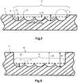
- the perspective view figure 3 and the sectional view figure 4illustrate the geometric shape of the hollow elements 7.
- a hollow element 7has the shape of a spherical part 6 whose projection on a plane M along an axis of symmetry AA 'of the sphere 6 is a square 7', the axis of symmetry AA 'passing through the center C of the sphere.
- a hollow elementcomprises four vertices S1, S2, S3, S4.
- a hollow member 7has a point P equidistant from four vertices S1 to S4 and a depth H.
- the center C of the hollow element 7is the center of the sphere 6 on which it rests, the latter having a radius R and a diameter D.
- each hollow element 7is adjacent with another hollow element 7.
- the distance dalso called “pitch”
- the pitch d between two adjacent equidistant points P1-P2 of two adjacent recessed elements 7is greater than or equal to 0.3 mm and less than 2 mm.
- the pitch d between two adjacent vertices P1-P2is equal to 1 mm.
- a pattern 5 comprising such hollow elements 7is more robust than a pattern with grooves, said grooves having a greater weakness especially during sidewalk grating.
- the vertices S of the plurality of hollow elements 7form connection zones 11. These connection zones are located below the average surface 10 of the sidewall 3.
- the set of vertices of the adjacent recessed elements 7are located on a surface 9 which is set back from the average surface 10.
- the hollow elements 7have a depth H less than a distance PF between the point P of the hollow element 7 and the average surface 10 of the sidewall 3, the distance PF being taken along the axis AA 'of the 7.
- the depth H of a recessed element 7is substantially equal to the depth H of each of the adjacent hollow elements 7.
- the depth His greater than the distance L.
- each hollow element 7has an angular aperture ⁇ less than or equal to 70 °.
- angular aperture ais meant, seen in section, the angle formed by two segments passing through the connecting zones 11 and joining at the center C of the recessed element 7. This avoids significant light absorption.
- the lightis poorly absorbed by the texture of the sidewall of the tire. So there is no so-called "black zone”.
- the lightis reflected in the same way (same angle of reflection) on the pattern 5 covering the hilly / hollow defect 8 as on the pattern 5 covering the portion of the flank 3 having no defect.
- the visual effect created by the hilly / hollow 8is practically no longer visible or at all, regardless of the position of the observer with respect to the sidewall of the tire.
- the entire pattern 5makes it possible to create a so-called "white” zone because of the optimized reflection of the light on this pattern 5.
- the recessed elements 7In order to increase the reflection of light, the recessed elements 7 have a texture that approximates a smooth, reflecting surface that does not scatter the light or reduce the reflected light intensity.
- the arithmetic mean-deviation parameter Ra representative of the surface roughnessis very small and is less than 30 ⁇ m. The amount of light returned is maximized.
- the density of hollow elements 7 in the pattern 5is greater than or equal to 0.2 elements per mm 2 .
- a simple example of a method of manufacturing a mold corresponding to the negative of the pattern 5is to perform machining by knurling the mold.
- the figure 6presents an alternative embodiment in which the tire comprises a housing 13 in the sidewall 3.
- the pattern 5is thus disposed in this housing 13 so that the protection of this pattern against the wear caused by, for example, by gratings with sidewalks.
- the hollow elements 7are at the bottom of the housing 13. In this non-limiting embodiment, the depth H is less than the distance L.
- connection zones 11are connected together at connection areas 11, these connection zones 11 being curved and having a connecting radius r, such that r ⁇ R / 3.
- the hollow elementsare molded by a portion of a mold, this mold part having previously undergone a knurling operation for molding the hollow elements.
- the pattern 5comprises non-aligned hollow elements 7.
Landscapes
- Engineering & Computer Science (AREA)
- Mechanical Engineering (AREA)
- Tires In General (AREA)
Description
Translated fromFrenchLa présente invention concerne un pneumatique en matériau caoutchoutique pour véhicule automobile comprenant un flanc et un motif formé sur ce flanc.The present invention relates to a rubber tire for a motor vehicle comprising a sidewall and a pattern formed on this sidewall.
Un pneumatique comporte de manière connue une carcasse interne, une bande de roulement, un bourrelet d'accrochage à une jante, un flanc, et un élément intérieur d'étanchéité. La carcasse interne est composée d'au moins une nappe carcasse de fils enrobés de caoutchouc. Lors d'une étape de fabrication du pneumatique, cette nappe carcasse est coupée puis assemblée sur un tambour. Cette nappe pouvant faire plusieurs fois le tour de ce tambour, il existe ainsi une pluralité de couches formées à partir d'une même nappe carcasse. Or, il est possible qu'au cours de la mise en place de la nappe, la fin de cette nappe ne coïncide pas exactement avec le début de cette nappe sur le tambour, de sorte qu'il existe un surplus de nappe dans l'assemblage. Cette superposition crée localement une surépaisseur sur l'ébauche crue du pneumatique. Une fois cette ébauche crue vulcanisée et le pneumatique en résultant gonflé, cette surépaisseur apparaît en creux au niveau du flanc du pneumatique. Or ce creux est particulièrement visible sur le pneumatique, notamment sous certaines conditions d'éclairage, ce qui peut constituer un motif de non achat par un consommateur alors même que ce défaut n'est pas préjudiciable à la sécurité. Afin de masquer ce défaut sur le flanc du pneumatique, selon un état de la technique antérieur décrit dans le brevet
Un problème de cet état de la technique est que le procédé de fabrication de ces motifs moirés est complexe et coûteux à mettre en oeuvre. Un autre problème est que ce motif n'apporte pas une esthétique satisfaisante vis-à-vis du consommateur.A problem of this state of the art is that the manufacturing process of these moire patterns is complex and expensive to implement. Another problem is that this pattern does not provide a satisfactory aesthetic vis-à-vis the consumer.
Un autre document
Dans ce contexte, la présente invention vise à masquer ce défaut de déformation flanc d'une manière plus simple, et ceci pour une grande majorité d'angle d'observation d'un consommateur.In this context, the present invention aims to hide this flank deformation defect in a simpler way, and this for a large majority of observation angle of a consumer.
Par « pneumatique », on entend tous les types de bandages élastiques soumis à une pression interne ou non.By "tire" is meant all types of elastic bandages subjected to internal pressure or not.
Par « bande de roulement » d'un pneumatique, on entend une quantité de matériau caoutchoutique délimitée par des surfaces latérales et par deux surfaces principales, l'une intérieure, et l'autre extérieure, ladite surface extérieure étant destinée à entrer en contact avec une chaussée lorsque le pneumatique roule.The term "tread" of a tire means a quantity of rubber material delimited by lateral surfaces and by two main surfaces, one inside and one outside, said outside surface being intended to come into contact with a roadway when the tire is rolling.
Par « bourrelet » d'un pneumatique, on entend une partie du pneumatique destinée à prendre assise sur une jante de roue.By "bead" of a tire means a portion of the tire intended to sit on a wheel rim.
Par « flanc » d'un pneumatique, on entend une surface latérale du pneumatique disposée entre la bande de roulement du pneumatique et un bourrelet de ce pneumatique.By "sidewall" of a tire is meant a side surface of the tire disposed between the tread of the tire and a bead of the tire.
Par « motif formé sur un flanc», on entend une partie de flanc présentant des caractéristiques d'état de surface homogène différentes du reste du flanc. Ce motif peut délivrer des informations techniques et légales, et d'autre part permettre aux consommateurs de distinguer l'origine du produit.By "pattern formed on a sidewall" is meant a flank portion having homogeneous surface-state characteristics different from the rest of the sidewall. This reason can deliver technical and legal information, and secondly allow consumers to distinguish the origin of the product.
Par « surface moyenne de flanc », on entend le prolongement de la surface du flanc au dessus du motif formé sur le flanc.By "average sidewall surface" is meant the extension of the surface of the sidewall above the pattern formed on the sidewall.
A cette fin, l'invention propose un pneumatique en matériau caoutchoutique comprenant un flanc et un motif formé dans ce flanc. Ce flanc s'étend selon une surface moyenne. Le motif comprend une pluralité d'éléments en creux, ces éléments en creux ayant la forme d'une partie de sphère. Ces éléments en creux se raccordent entre eux au niveau de zones de raccordement, ces zones de raccordement s'étendant au-dessous de la surface moyenne du flanc. Vue en coupe, tout ou partie des éléments en creux comporte une ouverture angulaire inférieure ou égale à 70°.To this end, the invention provides a tire made of rubber material comprising a sidewall and a pattern formed in this sidewall. This flank extends along a medium surface. The pattern comprises a plurality of hollow elements, these recessed elements having the shape of a sphere portion. These recessed elements are interconnected at connection areas, these connection areas extending below the average surface of the sidewall. Sectional view, all or part of the hollow elements has an angular opening less than or equal to 70 °.
Ainsi, comme on va le voir par la suite, l'architecture du motif permet d'éviter une trop grande absorption de la lumière par la texture du flanc du pneumatique. Les rayons lumineux provenant d'une même source lumineuse qui éclairent le flanc du pneumatique sont ainsi sensiblement déviés de la même manière sur le motif, aussi bien au niveau du motif recouvrant la partie déformée du flanc qu'au niveau du motif recouvrant le flanc où il n'y a pas de déformation.Thus, as we will see later, the architecture of the pattern avoids too much absorption of light by the texture of the sidewall of the tire. The light rays coming from the same light source which illuminate the sidewall of the tire are thus substantially deviated in the same manner on the pattern, both at the level of the pattern covering the deformed part of the sidewall and at the level of the pattern covering the sidewall where there is no deformation.
En outre, comme les zones de raccordement sont en-dessous de la surface moyenne du flanc, celles-ci sont mieux protégées contre des phénomènes de frottements, issus par exemple de râpages trottoirs. Ceci est notamment vrai lorsque les motifs sont de petites tailles, les efforts de frottement étant alors absorbés par les bords de flanc entourant le motif.In addition, as the connection areas are below the average surface of the sidewall, they are better protected against friction phenomena, for example from sidewalk gratings. This is particularly true when the patterns are small in size, the friction forces then being absorbed by the flank edges surrounding the pattern.
Enfin, l'ouverture angulaire choisie permet d'obtenir une meilleure surface de réflexion pour la lumière. Le motif apparaît ainsi plus clairement sur le flanc du pneumatique.Finally, the chosen angular aperture makes it possible to obtain a better reflection surface for the light. The pattern thus appears more clearly on the sidewall of the tire.
Selon des modes de réalisation non limitatifs, le pneumatique, peut comporter en outre une ou plusieurs caractéristiques supplémentaires parmi les suivantes :According to non-limiting embodiments, the tire may further comprise one or more additional characteristics among the following:
La densité d'éléments en creux dans le motif est supérieure ou égale à 0,2 éléments en creux par mm2. Cela permet de donner au motif un aspect plus uniforme vis-à-vis d'un observateur.The density of hollow elements in the pattern is greater than or equal to 0.2 recessed elements per mm2 . This gives the pattern a more uniform appearance vis-à-vis an observer.
Vue en coupe, tout ou partie des éléments en creux comporte une ouverture angulaire inférieure ou égale à 70°. Cela permet d'obtenir une meilleure surface de réflexion pour la lumière. Le motif apparaît ainsi plus clairement sur le flanc du pneumatique.Sectional view, all or part of the hollow elements has an angular opening less than or equal to 70 °. This provides a better reflection surface for the light. The pattern thus appears more clearly on the sidewall of the tire.
Les éléments en creux sont alignés les uns par rapport aux autres dans le motif. Les limites du motif sont ainsi mieux maîtrisées.The recessed elements are aligned with each other in the pattern. The limits of the pattern are thus better controlled.
Tout ou partie des éléments en creux comporte une rugosité de surface de paramètre Ra inférieur à 30 µm. Cela permet d'obtenir une surface proche d'une surface polie et ainsi de limiter la dispersion de la lumière.All or part of the hollow elements has a surface roughness of parameter Ra less than 30 microns. This makes it possible to obtain a surface close to a polished surface and thus to limit the dispersion of the light.
Les éléments en creux présentent un rayon R et ces éléments en creux se raccordent entre eux au niveau de zones de raccordement, ces zones de raccordement étant courbes et présentant un rayon de raccordement r, tel que r≤R/3.The recessed elements have a radius R and these hollow elements are interconnected at connection areas, these connection areas being curved and having a connecting radius r, such that r≤R / 3.
D'autres caractéristiques et avantages de l'invention ressortiront de la description suivante, donnée à titre d'exemple, sans caractère limitatif, en regard des dessins annexés sur lesquels :
- la
figure 1 représente schématiquement un flanc d'un pneumatique, ledit flanc comportant un motif faisant contraste par rapport à ce flanc ; - la
figure 2 est une représentation en perspective d'une pluralité d'éléments en creux constituant le motif de lafigure 1 ; - la
figure 3 représente une vue en perspective d'un élément en creux du motif de lafigure 1 ; - la
figure 4 représente une vue de profil d'un élément en creux du motif de lafigure 1 ; - la
figure 5 représente schématiquement une vue en coupe d'une partie des éléments en creux de lafigure 1 ; - la
figure 6 représente schématiquement une vue en coupe d'une variante de réalisation du motif de lafigure 1 ; - la
figure 7 représente schématiquement une variante de réalisation du motif de lafigure 1 .
- the
figure 1 schematically represents a sidewall of a tire, said sidewall having a contrasting pattern with respect to this sidewall; - the
figure 2 is a perspective representation of a plurality of recessed elements constituting the motif of thefigure 1 ; - the
figure 3 represents a perspective view of a hollow element of the pattern of thefigure 1 ; - the
figure 4 represents a profile view of a hollow element of the pattern of thefigure 1 ; - the
figure 5 schematically represents a sectional view of a part of the hollow elements of thefigure 1 ; - the
figure 6 schematically represents a sectional view of a variant embodiment of the pattern of thefigure 1 ; - the
figure 7 schematically represents a variant embodiment of the pattern of thefigure 1 .
Dans la description qui va suivre, des éléments sensiblement identiques ou similaires seront désignés par des références identiques.
La
Le motif 5 comprend une pluralité d'éléments en creux 7, également appelés éléments concaves 7. Le motif 5 s'étend sur tout ou partie de la surface du flanc 3 et en particulier sur la partie comprenant la déformation flanc 8 créé par le chevauchement de nappe carcasse du pneumatique 1. Le motif 5 recouvre ainsi tout le vallonnement/creux 8. Lorsque le motif 5 s'étend sur toute la surface circonférentielle du flanc 3, un observateur du pneumatique verra peu de différence visuelle entre le motif 5 et le flanc 3.In the following description, substantially identical or similar elements will be designated by identical references.
The
The
La
Chaque élément en creux 7 a la propriété particulière de renvoyer une quantité de lumière qui reste constante, même lorsque le motif est incliné d'un faible angle par rapport à une position d'origine correspondant dans l'exemple à la position sur le flanc sans déformation. Dans un exemple non limitatif, l'inclinaison de l'angle est inférieure à 5°, ce qui correspond à l'inclinaison du renfoncement créé par la déformation flanc par rapport à la surface du flanc sans déformation.The
Each
La vue en perspective
En outre, comme illustré sur la vue de profil de la
In addition, as shown in the profile view of the
Dans le motif 5, chaque élément en creux 7 est adjacent avec un autre élément en creux 7. Ainsi, comme illustré sur la
Comme on peut le voir sur la
Autrement dit, les éléments en creux 7 présentent une profondeur H inférieure à une distance PF entre le point P de l'élément en creux 7 et la surface moyenne 10 du flanc 3, la distance PF étant prise selon l'axe AA' de l'élément en creux 7. La profondeur H d'un élément en creux 7 est sensiblement égale à la profondeur H de chacun des éléments en creux adjacents 7. Dans ce mode de réalisation non limitatif illustré à la
Ainsi, le fait que les sommets S1 à S4 ne remontent pas jusqu'au niveau de la surface du flanc 3 permet d'avoir un motif 5 plus robuste notamment lors de râpage trottoir. Dans le cas contraire, à savoir si la distance L était nulle, il y aurait une faiblesse au niveau desdits sommets S qui pourraient en effet être abîmés par le râpage trottoir.
Par ailleurs, comme les éléments en creux 7 se situent sous la surface moyenne 10 du flanc 3, cela perturbe moins l'écoulement de l'air qui est ainsi plus fluide et qui suit donc mieux ladite surface moyenne 10 du flanc 3.
Dans un mode de réalisation non limitatif, vue en coupe (coupe droite
Cela évite une absorption de lumière importante. Les rayons lumineux incidents sur le motif 5 et donc sur les éléments en creux 7, sont réfléchis vers l'observateur. Avec ce motif 5, la lumière est peu absorbée par la texture du flanc du pneumatique. Il n'y a donc pas de zone dite « noire ». La lumière est réfléchie de la même manière (même angle de réflexion) sur le motif 5 recouvrant le défaut vallonnement/creux 8 que sur le motif 5 recouvrant la partie du flanc 3 ne comportant aucun défaut. Ainsi, l'effet visuel créé par le vallonnement/creux 8 n'est pratiquement plus visible voire plus du tout, quelque soit la position de l'observateur par rapport au flanc du pneumatique. L'ensemble du motif 5 permet de créer une zone dite « blanche » en raison de la réflexion optimisée de la lumière sur ce motif 5.In the
As can be seen on the
In other words, the
Thus, the fact that the vertices S1 to S4 do not go up to the level of the surface of the
Moreover, since the recessed
In a non-limiting embodiment, sectional view (straight section
This avoids significant light absorption. The light rays incident on the
Afin d'augmenter la réflexion de la lumière, les éléments en creux 7 présentent une texture qui se rapproche d'une surface lisse, réfléchissante, qui ne disperse pas la lumière ni ne réduit l'intensité lumineuse renvoyée. Ainsi, le paramètre écart-moyen arithmétique Ra représentatif de la rugosité de surface est très faible et est inférieur à 30µm. La quantité de lumière renvoyée est maximisée. Quel que soit la position de l'observateur et donc de l'oeil par rapport au pneumatique 1, et quel que soit la source lumineuse qui éclaire le flanc 3 du pneumatique, le motif 5 permet de masquer l'effet visuel créé par le défaut dû au chevauchement de nappe carcasse, à savoir la déformation flanc.In order to increase the reflection of light, the recessed
Afin d'obtenir un procédé de fabrication facile à mettre en oeuvre, dans un mode de réalisation non limitatif, la densité d'éléments en creux 7 dans le motif 5 est supérieure ou égale à 0,2 éléments par mm2. Ainsi, un exemple simple de procédé de fabrication d'un moule correspondant au négatif du motif 5 est d'effectuer un usinage par moletage du moule.In order to obtain a manufacturing method that is easy to implement, in a non-limiting embodiment, the density of
La
La
L'invention n'est pas limitée aux exemples décrits et représentés et diverses modifications peuvent y être apportées sans sortir de son cadre.The invention is not limited to the examples described and shown and various modifications can be made without departing from its scope.
Ainsi, dans un mode de réalisation non limitatif, les éléments en creux sont moulés par une partie d'un moule, cette partie de moule ayant préalablement subie une opération de moletage pour le moulage des éléments en creux.Thus, in a non-limiting embodiment, the hollow elements are molded by a portion of a mold, this mold part having previously undergone a knurling operation for molding the hollow elements.
Dans un autre mode de réalisation non limitatif, le motif 5 comprend des éléments en creux 7 non alignés.In another non-limiting embodiment, the
L'invention décrite présente notamment les avantages suivants :
- avec la texture proposée du motif, la quantité de lumière renvoyée varie très peu, même avec une variation locale d'angle de la surface du pneu créée par le renfoncement de la déformation. Ainsi, la régularité de la quantité de lumière provenant d'une source lumineuse, renvoyée vers un observateur par un élément en gomme, est améliorée. Et l'observateur perçoit ainsi une surface de couleur uniforme, malgré la variation locale de l'angle de la surface du flanc.
- avec les éléments en creux ainsi structurés, on évite l'absorption de la lumière et ainsi, on évite de créer une zone noire ;
- quelque soit la source lumineuse incidente qui éclaire le pneumatique (par exemple la lumière du soleil ou la lumière d'un magasin), il y a un masquage de la déformation flanc par le motif. La solution proposée ne dépend donc pas de la quantité de lumière réfléchie sur le flanc du pneumatique ;
- un observateur du pneumatique ne distingue pratiquement plus, voire plus du tout la déformation flanc ;
- le motif est plus robuste. Il présente ainsi une pérennité dans le temps ; et
- grâce à l'écoulement de l'air amélioré, on diminue la consommation du véhicule dans le temps.
- with the proposed texture of the pattern, the amount of light returned varies very little, even with a local angle variation of the tire surface created by the deformation recess. Thus, the regularity of the amount of light from a light source, returned to an observer by a rubber member, is improved. And the observer thus perceives a surface of uniform color, despite the local variation of the angle of the surface of the flank.
- with the hollow elements thus structured, it avoids the absorption of light and thus, it avoids creating a black area;
- whatever the incident light source that illuminates the tire (for example sunlight or light from a magazine), there is a masking of the flank deformation by the pattern. The proposed solution therefore does not depend on the amount of light reflected on the sidewall of the tire;
- an observer of the tire hardly distinguishes any more or at all the flank deformation;
- the pattern is more robust. It thus presents a durability over time; and
- thanks to the improved air flow, the consumption of the vehicle is reduced over time.
Claims (6)
- Tyre made of rubbery material comprising a sidewall (3) and a pattern (5) formed in this sidewall (3), the said sidewall extending along a mean surface (10), the said pattern (5) comprising a plurality of recessed elements (7), each recessed element (7) having the form of a part of a sphere, the said recessed elements (7) meeting each other at connection zones (11), the connection zones (11) extending under the mean surface (10) of the sidewall,characterized in that, viewed in cross section, all or part of the recessed elements (7) subtend an angle (α) less than or equal to 70°, the said angle (α) corresponds to the angle formed by two segments passing through the connection zones (11) and meeting at the centre C of the recessed element (7).
- Tyre according to Claim 1,characterized in that the density of recessed elements (7) within the pattern (5) is greater than or equal to 0.2 elements per mm2.
- Tyre according to one of Claims 1 to 2,characterized in that the recessed elements (7) are aligned with one another within the pattern (5).
- Tyre according to any one of Claims 1 to 3,characterized in that all or part of the recessed elements (7) have a surface roughness parameter Ra less than 30 µm.
- Tyre according to any one of Claims 1 to 4, the tyre comprising a housing (13) in the sidewall (3),characterized in that the pattern (5) is arranged in the said housing (13).
- Tyre according to any one of Claims 1 to 5, the recessed elements (7) having a radius R,characterized in that the connection zones (11) are curved and have a blend radius r such that r≤R/3.
Applications Claiming Priority (2)
| Application Number | Priority Date | Filing Date | Title |
|---|---|---|---|
| FR1361865AFR3014024B1 (en) | 2013-11-29 | 2013-11-29 | PNEUMATIC COMPRISING A DEFECT MASKING PATTERN ON A FLANK |
| PCT/EP2014/075598WO2015078882A1 (en) | 2013-11-29 | 2014-11-26 | Tyre comprising a defect-masking pattern on a sidewall |
Publications (2)
| Publication Number | Publication Date |
|---|---|
| EP3074246A1 EP3074246A1 (en) | 2016-10-05 |
| EP3074246B1true EP3074246B1 (en) | 2018-05-09 |
Family
ID=50179753
Family Applications (1)
| Application Number | Title | Priority Date | Filing Date |
|---|---|---|---|
| EP14803113.1AActiveEP3074246B1 (en) | 2013-11-29 | 2014-11-26 | Tyre comprising a defect-masking pattern on a sidewall |
Country Status (3)
| Country | Link |
|---|---|
| EP (1) | EP3074246B1 (en) |
| FR (1) | FR3014024B1 (en) |
| WO (1) | WO2015078882A1 (en) |
Families Citing this family (2)
| Publication number | Priority date | Publication date | Assignee | Title |
|---|---|---|---|---|
| DE102016218487A1 (en) | 2016-09-27 | 2018-03-29 | Continental Reifen Deutschland Gmbh | vehicle tires |
| JP7714961B2 (en)* | 2021-08-26 | 2025-07-30 | 住友ゴム工業株式会社 | Tire vulcanization mold, tire manufacturing method, and tire |
Family Cites Families (3)
| Publication number | Priority date | Publication date | Assignee | Title |
|---|---|---|---|---|
| LU80687A1 (en)* | 1977-12-23 | 1979-04-13 | Dunlop Ltd | SHALLOW GROUND PATTERNS ON TIRE SIDES |
| US5027876A (en)* | 1989-11-13 | 1991-07-02 | The Goodyear Tire & Rubber Company | Environmental tire |
| JP4803316B1 (en)* | 2010-11-17 | 2011-10-26 | 横浜ゴム株式会社 | Pneumatic tire |
- 2013
- 2013-11-29FRFR1361865Apatent/FR3014024B1/enactiveActive
- 2014
- 2014-11-26WOPCT/EP2014/075598patent/WO2015078882A1/enactiveApplication Filing
- 2014-11-26EPEP14803113.1Apatent/EP3074246B1/enactiveActive
Non-Patent Citations (1)
| Title |
|---|
| None* |
Also Published As
| Publication number | Publication date |
|---|---|
| EP3074246A1 (en) | 2016-10-05 |
| WO2015078882A1 (en) | 2015-06-04 |
| FR3014024A1 (en) | 2015-06-05 |
| FR3014024B1 (en) | 2017-02-24 |
Similar Documents
| Publication | Publication Date | Title |
|---|---|---|
| FR3054975B1 (en) | PNEUMATIC COMPRISING A MATRIX SYMBOL WITH HIGH CONTRAST ON THE FLANK | |
| EP3010730B1 (en) | Tire comprising a high-contrast marking | |
| EP3592577B1 (en) | Tyre provided with a texture on a sidewall | |
| EP2720887B1 (en) | Tyre comprising a high-contrast pattern and ribs for protecting the pattern | |
| WO2014040967A1 (en) | Tyre comprising a high contrast pattern comprising a plurality of cavities | |
| EP2788204B1 (en) | Combination of a heavy duty tire structure with a tread profile | |
| WO2012004285A1 (en) | Tread protection device | |
| WO2014202731A1 (en) | Tyre comprising high-contrast marking | |
| FR2921586A1 (en) | TIRE TREAD COMPRISING GUM PLOTS | |
| WO2015086447A1 (en) | Tyre comprising a particular graphic element | |
| EP3074247B1 (en) | Tyre comprising a defect-masking pattern on a sidewall | |
| FR3043018A1 (en) | HOLLOW HOLLOW BAND COMPRISING A WEAR INDICATOR HAVING IMPROVED VISIBILITY | |
| EP3074246B1 (en) | Tyre comprising a defect-masking pattern on a sidewall | |
| WO2015018762A1 (en) | Tire comprising a particular graphic element | |
| EP4301610A1 (en) | Sidewall insert for a motorcycle tyre | |
| EP3074245B1 (en) | Tyre comprising a defect-masking pattern on a sidewall | |
| WO2019053350A1 (en) | Mould for a tyre tread comprising concealed channels | |
| WO2015113921A1 (en) | Tire comprising a defect-masking pattern on a sidewall | |
| EP3558716B1 (en) | Tread for an agricultural vehicle tyre | |
| EP3898279A1 (en) | Tread comprising hidden cavities and grooves | |
| WO2020128235A1 (en) | Tread comprising hidden cavities and grooves |
Legal Events
| Date | Code | Title | Description |
|---|---|---|---|
| PUAI | Public reference made under article 153(3) epc to a published international application that has entered the european phase | Free format text:ORIGINAL CODE: 0009012 | |
| 17P | Request for examination filed | Effective date:20160629 | |
| AK | Designated contracting states | Kind code of ref document:A1 Designated state(s):AL AT BE BG CH CY CZ DE DK EE ES FI FR GB GR HR HU IE IS IT LI LT LU LV MC MK MT NL NO PL PT RO RS SE SI SK SM TR | |
| AX | Request for extension of the european patent | Extension state:BA ME | |
| DAX | Request for extension of the european patent (deleted) | ||
| RAP1 | Party data changed (applicant data changed or rights of an application transferred) | Owner name:COMPAGNIE GENERALE DES ETABLISSEMENTS MICHELIN | |
| RAP1 | Party data changed (applicant data changed or rights of an application transferred) | Owner name:COMPAGNIE GENERALE DES ETABLISSEMENTS MICHELIN | |
| GRAP | Despatch of communication of intention to grant a patent | Free format text:ORIGINAL CODE: EPIDOSNIGR1 | |
| INTG | Intention to grant announced | Effective date:20180212 | |
| GRAS | Grant fee paid | Free format text:ORIGINAL CODE: EPIDOSNIGR3 | |
| GRAA | (expected) grant | Free format text:ORIGINAL CODE: 0009210 | |
| AK | Designated contracting states | Kind code of ref document:B1 Designated state(s):AL AT BE BG CH CY CZ DE DK EE ES FI FR GB GR HR HU IE IS IT LI LT LU LV MC MK MT NL NO PL PT RO RS SE SI SK SM TR | |
| REG | Reference to a national code | Ref country code:GB Ref legal event code:FG4D Free format text:NOT ENGLISH | |
| REG | Reference to a national code | Ref country code:CH Ref legal event code:EP Ref country code:AT Ref legal event code:REF Ref document number:997237 Country of ref document:AT Kind code of ref document:T Effective date:20180515 | |
| REG | Reference to a national code | Ref country code:IE Ref legal event code:FG4D Free format text:LANGUAGE OF EP DOCUMENT: FRENCH | |
| REG | Reference to a national code | Ref country code:DE Ref legal event code:R096 Ref document number:602014025347 Country of ref document:DE | |
| REG | Reference to a national code | Ref country code:NL Ref legal event code:FP | |
| REG | Reference to a national code | Ref country code:LT Ref legal event code:MG4D | |
| PG25 | Lapsed in a contracting state [announced via postgrant information from national office to epo] | Ref country code:NO Free format text:LAPSE BECAUSE OF FAILURE TO SUBMIT A TRANSLATION OF THE DESCRIPTION OR TO PAY THE FEE WITHIN THE PRESCRIBED TIME-LIMIT Effective date:20180809 Ref country code:BG Free format text:LAPSE BECAUSE OF FAILURE TO SUBMIT A TRANSLATION OF THE DESCRIPTION OR TO PAY THE FEE WITHIN THE PRESCRIBED TIME-LIMIT Effective date:20180809 Ref country code:FI Free format text:LAPSE BECAUSE OF FAILURE TO SUBMIT A TRANSLATION OF THE DESCRIPTION OR TO PAY THE FEE WITHIN THE PRESCRIBED TIME-LIMIT Effective date:20180509 Ref country code:SE Free format text:LAPSE BECAUSE OF FAILURE TO SUBMIT A TRANSLATION OF THE DESCRIPTION OR TO PAY THE FEE WITHIN THE PRESCRIBED TIME-LIMIT Effective date:20180509 Ref country code:ES Free format text:LAPSE BECAUSE OF FAILURE TO SUBMIT A TRANSLATION OF THE DESCRIPTION OR TO PAY THE FEE WITHIN THE PRESCRIBED TIME-LIMIT Effective date:20180509 Ref country code:LT Free format text:LAPSE BECAUSE OF FAILURE TO SUBMIT A TRANSLATION OF THE DESCRIPTION OR TO PAY THE FEE WITHIN THE PRESCRIBED TIME-LIMIT Effective date:20180509 | |
| RAP2 | Party data changed (patent owner data changed or rights of a patent transferred) | Owner name:COMPAGNIE GENERALE DES ETABLISSEMENTS MICHELIN | |
| PG25 | Lapsed in a contracting state [announced via postgrant information from national office to epo] | Ref country code:HR Free format text:LAPSE BECAUSE OF FAILURE TO SUBMIT A TRANSLATION OF THE DESCRIPTION OR TO PAY THE FEE WITHIN THE PRESCRIBED TIME-LIMIT Effective date:20180509 Ref country code:LV Free format text:LAPSE BECAUSE OF FAILURE TO SUBMIT A TRANSLATION OF THE DESCRIPTION OR TO PAY THE FEE WITHIN THE PRESCRIBED TIME-LIMIT Effective date:20180509 Ref country code:GR Free format text:LAPSE BECAUSE OF FAILURE TO SUBMIT A TRANSLATION OF THE DESCRIPTION OR TO PAY THE FEE WITHIN THE PRESCRIBED TIME-LIMIT Effective date:20180810 Ref country code:RS Free format text:LAPSE BECAUSE OF FAILURE TO SUBMIT A TRANSLATION OF THE DESCRIPTION OR TO PAY THE FEE WITHIN THE PRESCRIBED TIME-LIMIT Effective date:20180509 | |
| REG | Reference to a national code | Ref country code:AT Ref legal event code:MK05 Ref document number:997237 Country of ref document:AT Kind code of ref document:T Effective date:20180509 | |
| PG25 | Lapsed in a contracting state [announced via postgrant information from national office to epo] | Ref country code:EE Free format text:LAPSE BECAUSE OF FAILURE TO SUBMIT A TRANSLATION OF THE DESCRIPTION OR TO PAY THE FEE WITHIN THE PRESCRIBED TIME-LIMIT Effective date:20180509 Ref country code:AT Free format text:LAPSE BECAUSE OF FAILURE TO SUBMIT A TRANSLATION OF THE DESCRIPTION OR TO PAY THE FEE WITHIN THE PRESCRIBED TIME-LIMIT Effective date:20180509 Ref country code:CZ Free format text:LAPSE BECAUSE OF FAILURE TO SUBMIT A TRANSLATION OF THE DESCRIPTION OR TO PAY THE FEE WITHIN THE PRESCRIBED TIME-LIMIT Effective date:20180509 Ref country code:RO Free format text:LAPSE BECAUSE OF FAILURE TO SUBMIT A TRANSLATION OF THE DESCRIPTION OR TO PAY THE FEE WITHIN THE PRESCRIBED TIME-LIMIT Effective date:20180509 Ref country code:DK Free format text:LAPSE BECAUSE OF FAILURE TO SUBMIT A TRANSLATION OF THE DESCRIPTION OR TO PAY THE FEE WITHIN THE PRESCRIBED TIME-LIMIT Effective date:20180509 Ref country code:PL Free format text:LAPSE BECAUSE OF FAILURE TO SUBMIT A TRANSLATION OF THE DESCRIPTION OR TO PAY THE FEE WITHIN THE PRESCRIBED TIME-LIMIT Effective date:20180509 Ref country code:SK Free format text:LAPSE BECAUSE OF FAILURE TO SUBMIT A TRANSLATION OF THE DESCRIPTION OR TO PAY THE FEE WITHIN THE PRESCRIBED TIME-LIMIT Effective date:20180509 | |
| REG | Reference to a national code | Ref country code:DE Ref legal event code:R097 Ref document number:602014025347 Country of ref document:DE | |
| PG25 | Lapsed in a contracting state [announced via postgrant information from national office to epo] | Ref country code:SM Free format text:LAPSE BECAUSE OF FAILURE TO SUBMIT A TRANSLATION OF THE DESCRIPTION OR TO PAY THE FEE WITHIN THE PRESCRIBED TIME-LIMIT Effective date:20180509 Ref country code:IT Free format text:LAPSE BECAUSE OF FAILURE TO SUBMIT A TRANSLATION OF THE DESCRIPTION OR TO PAY THE FEE WITHIN THE PRESCRIBED TIME-LIMIT Effective date:20180509 | |
| PLBE | No opposition filed within time limit | Free format text:ORIGINAL CODE: 0009261 | |
| STAA | Information on the status of an ep patent application or granted ep patent | Free format text:STATUS: NO OPPOSITION FILED WITHIN TIME LIMIT | |
| 26N | No opposition filed | Effective date:20190212 | |
| PG25 | Lapsed in a contracting state [announced via postgrant information from national office to epo] | Ref country code:SI Free format text:LAPSE BECAUSE OF FAILURE TO SUBMIT A TRANSLATION OF THE DESCRIPTION OR TO PAY THE FEE WITHIN THE PRESCRIBED TIME-LIMIT Effective date:20180509 | |
| REG | Reference to a national code | Ref country code:CH Ref legal event code:PL | |
| GBPC | Gb: european patent ceased through non-payment of renewal fee | Effective date:20181126 | |
| PG25 | Lapsed in a contracting state [announced via postgrant information from national office to epo] | Ref country code:LU Free format text:LAPSE BECAUSE OF NON-PAYMENT OF DUE FEES Effective date:20181126 Ref country code:MC Free format text:LAPSE BECAUSE OF FAILURE TO SUBMIT A TRANSLATION OF THE DESCRIPTION OR TO PAY THE FEE WITHIN THE PRESCRIBED TIME-LIMIT Effective date:20180509 | |
| REG | Reference to a national code | Ref country code:BE Ref legal event code:MM Effective date:20181130 | |
| REG | Reference to a national code | Ref country code:IE Ref legal event code:MM4A | |
| PG25 | Lapsed in a contracting state [announced via postgrant information from national office to epo] | Ref country code:CH Free format text:LAPSE BECAUSE OF NON-PAYMENT OF DUE FEES Effective date:20181130 Ref country code:LI Free format text:LAPSE BECAUSE OF NON-PAYMENT OF DUE FEES Effective date:20181130 | |
| PG25 | Lapsed in a contracting state [announced via postgrant information from national office to epo] | Ref country code:IE Free format text:LAPSE BECAUSE OF NON-PAYMENT OF DUE FEES Effective date:20181126 | |
| PG25 | Lapsed in a contracting state [announced via postgrant information from national office to epo] | Ref country code:AL Free format text:LAPSE BECAUSE OF FAILURE TO SUBMIT A TRANSLATION OF THE DESCRIPTION OR TO PAY THE FEE WITHIN THE PRESCRIBED TIME-LIMIT Effective date:20180509 Ref country code:BE Free format text:LAPSE BECAUSE OF NON-PAYMENT OF DUE FEES Effective date:20181130 | |
| PG25 | Lapsed in a contracting state [announced via postgrant information from national office to epo] | Ref country code:GB Free format text:LAPSE BECAUSE OF NON-PAYMENT OF DUE FEES Effective date:20181126 | |
| PG25 | Lapsed in a contracting state [announced via postgrant information from national office to epo] | Ref country code:MT Free format text:LAPSE BECAUSE OF FAILURE TO SUBMIT A TRANSLATION OF THE DESCRIPTION OR TO PAY THE FEE WITHIN THE PRESCRIBED TIME-LIMIT Effective date:20180509 | |
| PGFP | Annual fee paid to national office [announced via postgrant information from national office to epo] | Ref country code:NL Payment date:20191120 Year of fee payment:6 Ref country code:DE Payment date:20191121 Year of fee payment:6 | |
| PG25 | Lapsed in a contracting state [announced via postgrant information from national office to epo] | Ref country code:TR Free format text:LAPSE BECAUSE OF FAILURE TO SUBMIT A TRANSLATION OF THE DESCRIPTION OR TO PAY THE FEE WITHIN THE PRESCRIBED TIME-LIMIT Effective date:20180509 | |
| PG25 | Lapsed in a contracting state [announced via postgrant information from national office to epo] | Ref country code:PT Free format text:LAPSE BECAUSE OF FAILURE TO SUBMIT A TRANSLATION OF THE DESCRIPTION OR TO PAY THE FEE WITHIN THE PRESCRIBED TIME-LIMIT Effective date:20180509 | |
| PG25 | Lapsed in a contracting state [announced via postgrant information from national office to epo] | Ref country code:MK Free format text:LAPSE BECAUSE OF NON-PAYMENT OF DUE FEES Effective date:20180509 Ref country code:CY Free format text:LAPSE BECAUSE OF FAILURE TO SUBMIT A TRANSLATION OF THE DESCRIPTION OR TO PAY THE FEE WITHIN THE PRESCRIBED TIME-LIMIT Effective date:20180509 Ref country code:HU Free format text:LAPSE BECAUSE OF FAILURE TO SUBMIT A TRANSLATION OF THE DESCRIPTION OR TO PAY THE FEE WITHIN THE PRESCRIBED TIME-LIMIT; INVALID AB INITIO Effective date:20141126 | |
| PG25 | Lapsed in a contracting state [announced via postgrant information from national office to epo] | Ref country code:IS Free format text:LAPSE BECAUSE OF FAILURE TO SUBMIT A TRANSLATION OF THE DESCRIPTION OR TO PAY THE FEE WITHIN THE PRESCRIBED TIME-LIMIT Effective date:20180909 | |
| REG | Reference to a national code | Ref country code:DE Ref legal event code:R119 Ref document number:602014025347 Country of ref document:DE | |
| REG | Reference to a national code | Ref country code:NL Ref legal event code:MM Effective date:20201201 | |
| PG25 | Lapsed in a contracting state [announced via postgrant information from national office to epo] | Ref country code:NL Free format text:LAPSE BECAUSE OF NON-PAYMENT OF DUE FEES Effective date:20201201 | |
| PG25 | Lapsed in a contracting state [announced via postgrant information from national office to epo] | Ref country code:DE Free format text:LAPSE BECAUSE OF NON-PAYMENT OF DUE FEES Effective date:20210601 | |
| PGFP | Annual fee paid to national office [announced via postgrant information from national office to epo] | Ref country code:FR Payment date:20241128 Year of fee payment:11 |