EP3074084B1 - Anchor element deployment assembly for medical devices - Google Patents
Anchor element deployment assembly for medical devicesDownload PDFInfo
- Publication number
- EP3074084B1 EP3074084B1EP14863371.2AEP14863371AEP3074084B1EP 3074084 B1EP3074084 B1EP 3074084B1EP 14863371 AEP14863371 AEP 14863371AEP 3074084 B1EP3074084 B1EP 3074084B1
- Authority
- EP
- European Patent Office
- Prior art keywords
- anchor element
- anchor
- cannula
- medical device
- lobe
- Prior art date
- Legal status (The legal status is an assumption and is not a legal conclusion. Google has not performed a legal analysis and makes no representation as to the accuracy of the status listed.)
- Active
Links
- 210000001519tissueAnatomy0.000description9
- 238000000034methodMethods0.000description8
- 238000000429assemblyMethods0.000description6
- 230000000712assemblyEffects0.000description6
- 238000004873anchoringMethods0.000description4
- 230000001225therapeutic effectEffects0.000description4
- 238000013160medical therapyMethods0.000description3
- 210000003205muscleAnatomy0.000description3
- 210000000278spinal cordAnatomy0.000description3
- 230000000638stimulationEffects0.000description3
- 238000002560therapeutic procedureMethods0.000description3
- 230000007704transitionEffects0.000description3
- 238000001802infusionMethods0.000description2
- 230000014759maintenance of locationEffects0.000description2
- 239000000463materialSubstances0.000description2
- 238000012806monitoring deviceMethods0.000description2
- 210000005036nerveAnatomy0.000description2
- 229920000642polymerPolymers0.000description2
- 229920002635polyurethanePolymers0.000description2
- 239000004814polyurethaneSubstances0.000description2
- 229910000619316 stainless steelInorganic materials0.000description1
- 210000004556brainAnatomy0.000description1
- 230000000295complement effectEffects0.000description1
- 230000006835compressionEffects0.000description1
- 238000007906compressionMethods0.000description1
- 210000002808connective tissueAnatomy0.000description1
- 230000000694effectsEffects0.000description1
- 239000012530fluidSubstances0.000description1
- 230000002496gastric effectEffects0.000description1
- 238000003780insertionMethods0.000description1
- 230000037431insertionEffects0.000description1
- 230000007774longtermEffects0.000description1
- 239000007769metal materialSubstances0.000description1
- 238000012544monitoring processMethods0.000description1
- 210000000653nervous systemAnatomy0.000description1
- 206010033675panniculitisDiseases0.000description1
- 210000001428peripheral nervous systemAnatomy0.000description1
- 229920001296polysiloxanePolymers0.000description1
- 210000004304subcutaneous tissueAnatomy0.000description1
- 238000011282treatmentMethods0.000description1
Images


Classifications
- A—HUMAN NECESSITIES
- A61—MEDICAL OR VETERINARY SCIENCE; HYGIENE
- A61N—ELECTROTHERAPY; MAGNETOTHERAPY; RADIATION THERAPY; ULTRASOUND THERAPY
- A61N1/00—Electrotherapy; Circuits therefor
- A61N1/02—Details
- A61N1/04—Electrodes
- A61N1/05—Electrodes for implantation or insertion into the body, e.g. heart electrode
- A61N1/0551—Spinal or peripheral nerve electrodes
- A61N1/0558—Anchoring or fixation means therefor
- A—HUMAN NECESSITIES
- A61—MEDICAL OR VETERINARY SCIENCE; HYGIENE
- A61N—ELECTROTHERAPY; MAGNETOTHERAPY; RADIATION THERAPY; ULTRASOUND THERAPY
- A61N1/00—Electrotherapy; Circuits therefor
- A61N1/02—Details
- A61N1/04—Electrodes
- A61N1/05—Electrodes for implantation or insertion into the body, e.g. heart electrode
- A—HUMAN NECESSITIES
- A61—MEDICAL OR VETERINARY SCIENCE; HYGIENE
- A61B—DIAGNOSIS; SURGERY; IDENTIFICATION
- A61B17/00—Surgical instruments, devices or methods
- A61B17/04—Surgical instruments, devices or methods for suturing wounds; Holders or packages for needles or suture materials
- A61B17/0401—Suture anchors, buttons or pledgets, i.e. means for attaching sutures to bone, cartilage or soft tissue; Instruments for applying or removing suture anchors
- A—HUMAN NECESSITIES
- A61—MEDICAL OR VETERINARY SCIENCE; HYGIENE
- A61B—DIAGNOSIS; SURGERY; IDENTIFICATION
- A61B17/00—Surgical instruments, devices or methods
- A61B17/34—Trocars; Puncturing needles
- A61B17/3468—Trocars; Puncturing needles for implanting or removing devices, e.g. prostheses, implants, seeds, wires
- A—HUMAN NECESSITIES
- A61—MEDICAL OR VETERINARY SCIENCE; HYGIENE
- A61B—DIAGNOSIS; SURGERY; IDENTIFICATION
- A61B5/00—Measuring for diagnostic purposes; Identification of persons
- A61B5/68—Arrangements of detecting, measuring or recording means, e.g. sensors, in relation to patient
- A61B5/6846—Arrangements of detecting, measuring or recording means, e.g. sensors, in relation to patient specially adapted to be brought in contact with an internal body part, i.e. invasive
- A61B5/6879—Means for maintaining contact with the body
- A61B5/6882—Anchoring means
- A—HUMAN NECESSITIES
- A61—MEDICAL OR VETERINARY SCIENCE; HYGIENE
- A61M—DEVICES FOR INTRODUCING MEDIA INTO, OR ONTO, THE BODY; DEVICES FOR TRANSDUCING BODY MEDIA OR FOR TAKING MEDIA FROM THE BODY; DEVICES FOR PRODUCING OR ENDING SLEEP OR STUPOR
- A61M25/00—Catheters; Hollow probes
- A—HUMAN NECESSITIES
- A61—MEDICAL OR VETERINARY SCIENCE; HYGIENE
- A61M—DEVICES FOR INTRODUCING MEDIA INTO, OR ONTO, THE BODY; DEVICES FOR TRANSDUCING BODY MEDIA OR FOR TAKING MEDIA FROM THE BODY; DEVICES FOR PRODUCING OR ENDING SLEEP OR STUPOR
- A61M25/00—Catheters; Hollow probes
- A61M25/01—Introducing, guiding, advancing, emplacing or holding catheters
- A61M25/02—Holding devices, e.g. on the body
- A61M25/04—Holding devices, e.g. on the body in the body, e.g. expansible
- A—HUMAN NECESSITIES
- A61—MEDICAL OR VETERINARY SCIENCE; HYGIENE
- A61M—DEVICES FOR INTRODUCING MEDIA INTO, OR ONTO, THE BODY; DEVICES FOR TRANSDUCING BODY MEDIA OR FOR TAKING MEDIA FROM THE BODY; DEVICES FOR PRODUCING OR ENDING SLEEP OR STUPOR
- A61M31/00—Devices for introducing or retaining media, e.g. remedies, in cavities of the body
- A—HUMAN NECESSITIES
- A61—MEDICAL OR VETERINARY SCIENCE; HYGIENE
- A61N—ELECTROTHERAPY; MAGNETOTHERAPY; RADIATION THERAPY; ULTRASOUND THERAPY
- A61N1/00—Electrotherapy; Circuits therefor
- A61N1/02—Details
- A61N1/04—Electrodes
- A61N1/05—Electrodes for implantation or insertion into the body, e.g. heart electrode
- A61N1/056—Transvascular endocardial electrode systems
- A61N1/057—Anchoring means; Means for fixing the head inside the heart
- A—HUMAN NECESSITIES
- A61—MEDICAL OR VETERINARY SCIENCE; HYGIENE
- A61N—ELECTROTHERAPY; MAGNETOTHERAPY; RADIATION THERAPY; ULTRASOUND THERAPY
- A61N1/00—Electrotherapy; Circuits therefor
- A61N1/02—Details
- A61N1/04—Electrodes
- A61N1/05—Electrodes for implantation or insertion into the body, e.g. heart electrode
- A61N1/0587—Epicardial electrode systems; Endocardial electrodes piercing the pericardium
- A61N1/059—Anchoring means
- A—HUMAN NECESSITIES
- A61—MEDICAL OR VETERINARY SCIENCE; HYGIENE
- A61N—ELECTROTHERAPY; MAGNETOTHERAPY; RADIATION THERAPY; ULTRASOUND THERAPY
- A61N1/00—Electrotherapy; Circuits therefor
- A61N1/18—Applying electric currents by contact electrodes
- A61N1/32—Applying electric currents by contact electrodes alternating or intermittent currents
- A61N1/36—Applying electric currents by contact electrodes alternating or intermittent currents for stimulation
- A61N1/3605—Implantable neurostimulators for stimulating central or peripheral nerve system
- A—HUMAN NECESSITIES
- A61—MEDICAL OR VETERINARY SCIENCE; HYGIENE
- A61N—ELECTROTHERAPY; MAGNETOTHERAPY; RADIATION THERAPY; ULTRASOUND THERAPY
- A61N1/00—Electrotherapy; Circuits therefor
- A61N1/18—Applying electric currents by contact electrodes
- A61N1/32—Applying electric currents by contact electrodes alternating or intermittent currents
- A61N1/36—Applying electric currents by contact electrodes alternating or intermittent currents for stimulation
- A61N1/362—Heart stimulators
- A—HUMAN NECESSITIES
- A61—MEDICAL OR VETERINARY SCIENCE; HYGIENE
- A61N—ELECTROTHERAPY; MAGNETOTHERAPY; RADIATION THERAPY; ULTRASOUND THERAPY
- A61N1/00—Electrotherapy; Circuits therefor
- A61N1/18—Applying electric currents by contact electrodes
- A61N1/32—Applying electric currents by contact electrodes alternating or intermittent currents
- A61N1/36—Applying electric currents by contact electrodes alternating or intermittent currents for stimulation
- A61N1/372—Arrangements in connection with the implantation of stimulators
- A61N1/375—Constructional arrangements, e.g. casings
- A61N1/37518—Anchoring of the implants, e.g. fixation
- A—HUMAN NECESSITIES
- A61—MEDICAL OR VETERINARY SCIENCE; HYGIENE
- A61B—DIAGNOSIS; SURGERY; IDENTIFICATION
- A61B17/00—Surgical instruments, devices or methods
- A61B17/34—Trocars; Puncturing needles
- A61B17/3415—Trocars; Puncturing needles for introducing tubes or catheters, e.g. gastrostomy tubes, drain catheters
- A—HUMAN NECESSITIES
- A61—MEDICAL OR VETERINARY SCIENCE; HYGIENE
- A61B—DIAGNOSIS; SURGERY; IDENTIFICATION
- A61B17/00—Surgical instruments, devices or methods
- A61B2017/00982—General structural features
- A61B2017/00986—Malecots, e.g. slotted tubes, of which the distal end is pulled to deflect side struts
- A—HUMAN NECESSITIES
- A61—MEDICAL OR VETERINARY SCIENCE; HYGIENE
- A61B—DIAGNOSIS; SURGERY; IDENTIFICATION
- A61B17/00—Surgical instruments, devices or methods
- A61B17/04—Surgical instruments, devices or methods for suturing wounds; Holders or packages for needles or suture materials
- A61B17/0401—Suture anchors, buttons or pledgets, i.e. means for attaching sutures to bone, cartilage or soft tissue; Instruments for applying or removing suture anchors
- A61B2017/0409—Instruments for applying suture anchors
- A—HUMAN NECESSITIES
- A61—MEDICAL OR VETERINARY SCIENCE; HYGIENE
- A61B—DIAGNOSIS; SURGERY; IDENTIFICATION
- A61B17/00—Surgical instruments, devices or methods
- A61B17/04—Surgical instruments, devices or methods for suturing wounds; Holders or packages for needles or suture materials
- A61B17/0401—Suture anchors, buttons or pledgets, i.e. means for attaching sutures to bone, cartilage or soft tissue; Instruments for applying or removing suture anchors
- A61B2017/0419—H-fasteners
- A—HUMAN NECESSITIES
- A61—MEDICAL OR VETERINARY SCIENCE; HYGIENE
- A61B—DIAGNOSIS; SURGERY; IDENTIFICATION
- A61B17/00—Surgical instruments, devices or methods
- A61B17/04—Surgical instruments, devices or methods for suturing wounds; Holders or packages for needles or suture materials
- A61B17/0401—Suture anchors, buttons or pledgets, i.e. means for attaching sutures to bone, cartilage or soft tissue; Instruments for applying or removing suture anchors
- A61B2017/0427—Suture anchors, buttons or pledgets, i.e. means for attaching sutures to bone, cartilage or soft tissue; Instruments for applying or removing suture anchors having anchoring barbs or pins extending outwardly from the anchor body
- A61B2017/0437—Suture anchors, buttons or pledgets, i.e. means for attaching sutures to bone, cartilage or soft tissue; Instruments for applying or removing suture anchors having anchoring barbs or pins extending outwardly from the anchor body the barbs being resilient or spring-like
- A—HUMAN NECESSITIES
- A61—MEDICAL OR VETERINARY SCIENCE; HYGIENE
- A61B—DIAGNOSIS; SURGERY; IDENTIFICATION
- A61B17/00—Surgical instruments, devices or methods
- A61B17/04—Surgical instruments, devices or methods for suturing wounds; Holders or packages for needles or suture materials
- A61B17/0401—Suture anchors, buttons or pledgets, i.e. means for attaching sutures to bone, cartilage or soft tissue; Instruments for applying or removing suture anchors
- A61B2017/0464—Suture anchors, buttons or pledgets, i.e. means for attaching sutures to bone, cartilage or soft tissue; Instruments for applying or removing suture anchors for soft tissue
- A—HUMAN NECESSITIES
- A61—MEDICAL OR VETERINARY SCIENCE; HYGIENE
- A61M—DEVICES FOR INTRODUCING MEDIA INTO, OR ONTO, THE BODY; DEVICES FOR TRANSDUCING BODY MEDIA OR FOR TAKING MEDIA FROM THE BODY; DEVICES FOR PRODUCING OR ENDING SLEEP OR STUPOR
- A61M25/00—Catheters; Hollow probes
- A61M25/01—Introducing, guiding, advancing, emplacing or holding catheters
- A61M25/02—Holding devices, e.g. on the body
- A61M2025/0293—Catheter, guide wire or the like with means for holding, centering, anchoring or frictionally engaging the device within an artificial lumen, e.g. tube
Definitions
- the disclosurerelates generally to the field of medical devices and related methods.
- the disclosurerelates to anchor elements and anchor element assemblies that may be utilized to retain at least a portion of a medical device (e.g., a medical therapy delivery device) within a subject and related methods.
- a medical devicee.g., a medical therapy delivery device
- Implantable medical devicese.g ., medical therapy delivery devices
- catheters and leadsmay be employed for a variety of therapeutic and diagnostic purposes.
- Controlled placement and retention of such therapy delivery elements within a subjectis highly desirable as precise placement and retention may result in improved therapeutic efficacy or reduced side effects.
- the location of the delivery elementmay change in time. For example, as the subject moves, the location of the implanted delivery element may move or shift within the subject.
- Anchorsmay be placed about the therapy delivery element and sutured to subcutaneous tissue of the subject in order to secure the position of a delivery region of the therapy delivery element (e.g ., an infusion section or electrode of the delivery element) relative to a target location of the subject.
- a delivery region of the therapy delivery elemente.g ., an infusion section or electrode of the delivery element
- WO 2013/070490shows an anchoring tool for an implantable medical device.
- US 2008/0183257 , US 4 419 819 and EP 0 779 080show examples of known lead anchor elements.
- anchor elementsDescribed are anchor elements, anchor element assemblies, and methods of anchoring at least a portion of a medical device within a subject.
- Such anchor elementsmay be positioned and/or deployed within the subject while the at least a portion of the medical device is positioned within ( e.g ., resident in) a subject.
- such anchor elementsmay be positioned and/or deployed within the subject with an anchor deployment device of an anchor element assembly.
- an anchor element assemblycomprises at least one anchor element having a longitudinal axis.
- This anchor elementincludes at least one lobe section comprising at least one lobe configured to extend transversely or laterally from the longitudinal axis of the at least one anchor element when the anchor element is in a deployed state and a lumen formed within the at least one anchor element configured to receive at least a portion of a medical device in the lumen.
- the anchor element assemblyfurther comprises an anchor deployment device comprising at least one cannula configured to receive the at least one anchor element on the at least one cannula. The anchor deployment device is configured to secure the anchor deployment device to the at least a portion of the medical device.
- an anchor element comprising at least one protrusion sectioncomprises at least two circumferentially-spaced protrusions configured to extend transversely or laterally from a longitudinal axis of the anchor element when the anchor element is in a deployed state and a lumen formed within the at least one anchor element configured to receive at least a portion of a medical device in the lumen.
- the anchor elementis configured to be secured over the at least a portion of the medical device while the at least a portion of the medical device is positioned within a subject.
- the methodincludes positioning at least a portion of the medical device within the subject, securing the at least a portion of the medical device within a lumen of the at least one anchor element, and deploying at least one protrusion of the at least one anchor element to extend transversely or laterally from a longitudinal axis of the at least one anchor element while the at least a portion of the medical device is positioned within the subject.
- medical device assembliesincluding such anchor elements and/or anchor element assemblies.
- FIG. 1depicts a medical device assembly including an anchor element 100 positioned on a medical device 102 (e.g., a distal portion of the medical device 102).
- medical devices 102may include a diagnostic device, a monitoring device, a therapeutic device, or combinations thereof.
- the medical device 102may comprise a medical therapy delivery device, a medical device configured to sense a parameter of the subject, a medical device configured to diagnose a condition, a medical device configured to sample one or more tissues and/or fluids from a subject, or combinations thereof.
- the medical device 102may be utilized alone to provide a medical service (e.g ., diagnostic, monitoring, therapeutic, or combinations thereof) to a subject or may be utilized with one or more medical devices 103 (e.g ., a medical device internal or external to the subject that is electrically and/or mechanically coupled to the medical device 102).
- the medical device 102 and/or device 103may comprise devices such as a pacemaker, defibrillator, monitoring device, infusion device, neurostimulator, gastric stimulator, cochlear device, or any other device that is at least partially subcutaneously implanted in a subject.
- the medical device 102is positioned proximate the nervous system of a subject (e.g ., proximate the spinal cord or canal, brain, and/or peripheral nervous system).
- the medical device 102may be a catheter, a lead, or lead extension.
- the medical device 102may be a lead including one or more electrodes on a distal end portion of the lead. Electrical contacts in the lead may be electrically coupled ( e.g ., physically or wirelessly) to a control module having an electrical signal generator (e.g ., medical device 103 external or internal to the subject) and signals generated by the medical device 103 may be delivered to the subject via the electrodes.
- an electrical signal generatore.g ., medical device 103 external or internal to the subject
- such leadsare utilized as implantable stimulation devices, which may be utilized in a variety of treatments and procedures, such as, for example, spinal cord stimulation.
- implantable stimulation devicesmay be used to stimulate nerves, such as the spinal cord, muscles, or other tissue.
- the stimulator electrodes of the leadsmay be implanted in contact with or near the nerves, muscles, or other tissue to be stimulated.
- a pulse generator of the medical device 103generates electrical pulses that are delivered by the electrodes to body tissue.
- the leadis anchored at one or more places in the subject to prevent or reduce movement of the lead or stimulator electrodes within the subject ( e.g ., during short-term or long-term placement of the devices 102, 103 in the subject) that could damage tissue, move the stimulator electrodes out of the desired position, or interrupt the connection between the stimulator electrodes and the medical device 102, 103.
- the anchor element 100is placed over at least a portion of the medical device 102 (e.g., a cannula of the medical device 102).
- the medical device 102e.g., a cannula of the medical device 102
- at least a portion of the medical device 102may be positioned within a lumen formed by the tubular body ( e.g ., cannula) of the anchor element 100.
- the anchor element 100is shown in a deployed state where one or more protrusions (e.g ., one, two, three, four, or more lobes 104, e.g., circumferentially-spaced lobes) extend outwardly from a portion of the anchor element 100 ( e.g ., laterally outward from a longitudinal axis or centerline of the anchor element 100).
- Each lobe 104 extending laterally from the anchor element 100may form an opening 107 within the lobe 104.
- the lobes 104 of the anchor element 100may anchor the medical device 102 by engaging with one or more portions of the subject.
- the lobes 104 of the anchor element 100may engage with a portion of the subject's tissue (e.g., muscle tissue, nervous tissue, connective tissue, etc. ) to at least partially retain the medical device 102 in a desired position within the subject. It is also believed that, in some embodiments, regrowth of the tissue of the subject proximate the lobes 104 may intertwine with at least a portion of the lobes 104 (e.g ., tissue may extend through the openings 107) further anchoring the anchor element 100 and medical device 102 within the subject.
- tissuee.g., muscle tissue, nervous tissue, connective tissue, etc.
- the anchor element 100may be coupled ( e.g ., mechanically coupled) to at least a portion of the medical device 102 ( e.g ., an outer portion or exterior surface of the medical device 102).
- the anchor element 100may be secured to the medical device 102 through mechanical interference (e.g ., utilizing friction, compression, swaging, etc.) rather than through adhesion or the use of fasteners.
- the anchor element 100may include one or more portions for retaining the anchor element 100 to the medical device 102.
- engagement portions 106, 108may be formed on either side of the lobes 104 and may act to secure the anchor element 100 to the medical device 102 ( e.g ., via a mechanical interference fit).
- each of the engagement portions 106, 108 of the anchor element 100include an inner dimension (e.g ., diameter) that is smaller than an outer dimension ( e.g ., diameter) of the medical device 102.
- One or more portions of the anchor element 100may be formed from a flexible material (e.g ., an elastically deformable material) such as, for example, a polymer ( e.g ., silicone, polyurethane, etc .) .
- the flexible engagement portions 106, 108may be deformed (e.g ., elastically deformed) to enlarge a cross-sectional area of a lumen formed within each the engagement portions 106, 108.
- the enlarged engagement portions 106, 108may be positioned over ( e.g ., around, about) the medical device 102. As the enlarged engagement portions 106, 108 are allowed to contract back to substantially their original size ( e.g ., cross-sectional area), the engagement portions 106, 108 may engage and couple with the medical device 102.
- one or more ends of the anchor element 100include a taper 110 or chamfer to assist in insertion of the anchor element 100 into the subject.
- FIGS. 2A and 2Bdepict an anchor element (e.g ., anchor element 100) in an initial state (e.g., a retracted or relaxed state) and a deployed state (e.g ., a semi-distended state of the inner diameter), respectively.
- the anchor element 100includes a protrusion or lobe portion 105 positioned between the engagement portions 106, 108 of the anchor element 100.
- the body of the anchor elementmay form a lumen 101 therein.
- the lobes 104(e.g., two lobes 104) of the lobe portion 105 are formed about the anchor element 100 ( e.g., at equal circumferential spacing) by slits 112 in the tubular body of the anchor element 100.
- the lobe portion 105 of the anchor element 100is substantially parallel to ( e.g ., coextensive with) a longitudinal axis L 100 of the anchor element 100.
- the engagement portions 106, 108may be moved toward each other to transition the anchor element 100 to the deployed state.
- the slits 112enable the lobes 104 to extend outwardly ( e.g ., in a direction lateral or transverse ( e.g ., perpendicular) to the longitudinal axis L 100 of the anchor element 100) from a portion of the anchor element 100 ( e.g ., from the engagement portions 106, 108).
- FIGS. 3A and 3Bdepict an anchor element 200 in an initial state (e.g ., a retracted state) and a deployed state, respectively.
- the anchor element 200may be somewhat similar to anchor element 100 discussed above and the body of the anchor element 200 may form a lumen 201 therein.
- anchor element 200may include more than one lobe portion (e.g ., two lobe portions 205, 207) positioned between the engagement portions 206, 208 of the anchor element 200.
- the anchor element 200includes three, four, or more lobe portions.
- Lobes 204(e.g., two lobes) of each lobe portion 205, 207 are formed about the anchor element 200 ( e.g., at equal circumferential spacing) by slits 212 in the tubular body of the anchor element 200.
- the lobe portions 205 of the anchor element 200are substantially parallel to ( e.g ., coextensive with) a longitudinal axis L 200 of the anchor element 200.
- the anchor element 200includes an additional engagement portion 209 positioned between the lobe portions 205, 207.
- the engagement portions 206, 208may be moved toward each other ( e.g ., toward the additional engagement portion 209) to transition the anchor element 200 to the deployed state.
- the slits 212enable the lobes 204 to extend outwardly ( e.g., in a direction lateral or transverse ( e.g ., perpendicular) to a longitudinal axis L 200 of the anchor element 200) from a portion of the anchor element 200 ( e.g ., from the engagement portions 206, 208).
- the lobe portions 205, 207may be offset from one another ( e.g ., offset 90 degrees about the longitudinal axis L 200 of the anchor element 200).
- FIG. 4depicts an anchor deployment device 300 that may be utilized with an anchor element (e.g ., anchor elements 100, 200 discussed above with reference to FIGS. 1 through 3B ).
- the anchor deployment device 300includes a first cannula (e.g., deployment cannula 302) and a second cannula (e.g., anchor cannula 304) received at least partially within the deployment cannula 302.
- the deployment cannula 302may have an inner dimension (e.g ., diameter) that is greater than an outer dimension (e.g ., diameter) of the anchor cannula 304 such that the anchor cannula 304 may be received and movable within the deployment cannula 302.
- the anchor deployment device 300may include a handle 306 having a first portion 308 coupled to the deployment cannula 302 and a second portion 310 coupled to the anchor cannula 304.
- the portions 308, 310 of the handle 310may be movable relative to one another (e.g., the second portion 310 may slide relative to the first portion 308) in order to move the anchor cannula 304 within the deployment cannula 302.
- Each portion 308, 310 of the handle 306may include one or more grips 314 enabling a user ( e.g ., medical practitioner) to actuate the handle 306, thereby sliding the second portion 310 relative to the first portion 308 along a common axis.
- a usere.g ., medical practitioner
- the anchor cannula 304may be sized to receive an anchor element (e.g ., anchor element 100) on the anchor cannula 304 at distal portion 312 of the anchor deployment device 300.
- the outer dimension (e.g ., diameter) of the anchor cannula 304may be greater than the inner dimension ( e.g ., diameter) of the anchor element 100.
- Such a diameter of the anchor cannula 304may act to enlarge a cross-sectional area of a lumen 101 formed within a portion of the anchor element 100 ( e.g., at each of the engagement portions 106, 108 ( FIG. 1 )) to form an initial dimension to an enlarged dimension.
- the anchor cannula 304may deform (e.g ., elastically deform) the anchor element 100 to a dimension ( e.g ., diameter) that is greater than a dimension ( e.g., diameter) of the medical device 102 ( FIG. 1 ) on which the anchor element 100 is to be placed.
- FIG. 5depicts a view of the anchor deployment device 300 shown in FIG. 4 beginning to deploy an anchor element (e.g ., anchor element 100 in a distended state of the inner diameter).
- an anchor elemente.g ., anchor element 100 in a distended state of the inner diameter.
- at least a portion of a medical devicee.g ., medical device 102
- the anchor cannula 304may have an inner dimension ( e.g ., diameter) that is sized to enable at least a portion of the medical device 102 to be received within the anchor cannula 304.
- a proximal portion 316 of the anchor deployment device 300is configured such that the medical device 102 extends through the anchor deployment device 300 and out of the of the anchor deployment device 300 at the proximal portion 316.
- Such a configurationmay enable a user to position the anchor deployment device 300 along and through the medical device 102 in order to secure an anchor element 100 to the anchor deployment device 300 at any desired position.
- the medical device 102may be placed within a subject and the anchor deployment device 300 may be slid along the medical device 102.
- a portion of the anchor deployment device 300e.g., the distal portion 312 may be inserted within the subject to secure the anchor element 100 within the subject while the medical device 102 resides within the subject.
- Actuation of the handle 306may bring the anchor element 100, which is positioned on the anchor cannula 304 ( e.g., in a radially enlarged or stretched state), into contact with the deployment cannula 302 ( e.g., a leading end 318 of the deployment cannula 302).
- the deployment cannula 302may act to force ( e.g., slide) at least a portion of the anchor element 100 along the anchor cannula 304.
- the deployment cannula 302may force the first engagement portion 106 toward the second engagement portion 108, thereby deploying the lobes 104 of the anchor element 100.
- the leading end 318 of the deployment cannula 302may force the anchor element 100 off of the anchor cannula 304 and onto the medical device 102 ( e.g ., into the position shown in FIG. 1 ).
- FIG. 6depicts a cross-sectional view of a portion of the anchor deployment device 300 shown in FIG. 4 with the medical device 102 received in the anchor deployment device 300.
- the inner diameter ID 304 of the anchor cannula 304is sized to enable the medical device 102 to be received within the anchor cannula 304.
- the inner diameter ID 302 of the deployment cannula 302may be greater than an outer dimension OD 304 of the anchor cannula 304 such that the anchor cannula 304 may be received and movable within the deployment cannula 302.
- FIG. 7depicts another cross-sectional view of a portion of the anchor deployment device 300 shown in FIG. 4 with the medical device 102 received in the anchor deployment device 300 and the anchor element 100 attached to the anchor deployment device 300.
- the outer diameter OD 304 of the anchor cannula 304may be greater than an inner diameter of the anchor element 100 such that the anchor cannula 304 acts to enlarge a cross-sectional area of the lumen formed within a portion of the anchor element 100 to form an enlarged inner diameter ID 100 of the anchor element 100 that is substantially equal to the outer diameter OD 304 of the anchor cannula 304.
- the enlarged inner diameter ID 100 of the anchor element 100may be greater than an outer diameter OD 102 of the medical device 102 such that the enlarged inner diameter ID 100 of the anchor element 100 may be deployed over the outer diameter OD 102 of the medical device 102.
- the anchor element 100may contract toward the initial diameter to the anchor element 100 ( e.g., where the initial diameter of the anchor element 100 is less than the outer diameter OD 102 of the medical device 102) in order to secure the anchor element 100 to the medical device 102.
- FIGS. 8A and 8Bdepict an anchor element 400 in an initial state and a deployed state, respectively.
- the anchor element 400may be similar to and include one or more of the same features and functioning as the anchor elements 100, 200 discussed above with reference to FIGS. 1 through 3B .
- the anchor element 400includes a lobe portion 405 positioned between the engagement portions 406, 408 of the anchor element 400.
- the body of the anchor element 400may form a lumen 401 therein.
- Lobes 404e.g ., two lobes
- the lobe portion 405are formed about the anchor element 400 ( e.g ., at equal circumferential spacing) by slits 412 in the tubular body of the anchor element 400.
- the lobe portion 405 of the anchor element 400is substantially parallel to ( e.g ., coextensive with) a longitudinal axis L 400 of the anchor element 400.
- the engagement portions 406, 408may be moved toward each other to transition the anchor element 400 to the deployed state.
- the slits 412enable the lobes 404 to extend outwardly ( e.g ., in a direction lateral or transverse ( e.g., perpendicular) to the longitudinal axis L 400 of the anchor element 400) from a portion of the anchor element 400 ( e.g ., from the engagement portions 406, 408).
- the anchor element 400may include a biasing feature (e.g ., a radial biasing feature).
- the anchor element 400may include one or more springs 414 extending about at least a portion of the anchor element 400 ( e.g ., the engagement portions 406, 408).
- the springs 414are disposed on an exterior portion of the anchor element 400.
- the springs 414may be disposed within the anchor element 400. The springs 414 may act to bias the anchor element 400 in ( e.g ., toward) an initial state.
- the springs 414may act to radially bias the engagement portions 406, 408 of the anchor element 400 inward in a direction toward the lumen 401 ( e.g ., constricting the lumen 401) such that the springs 414 bias the engagement portions 406, 408 to or toward an initial state ( e.g., an unstretched inner diameter of the anchor element 400).
- the springs 414act to relatively more rapidly tighten the anchor element 400 around a medical device 102 ( see , e.g ., FIG. 5 ).
- any anchor element disclosed hereinmay include a radial biasing feature (e.g ., springs).
- the anchor elementmay include an axial biasing feature.
- FIGS. 9 and 10depict a perspective view and a side view, respectively, of an anchor deployment device 500.
- the anchor deployment device 500may be similar to and include one or more of the same features and functioning as the anchor deployment device 300 discussed above with reference to FIGS. 4 through 7 .
- the anchor deployment device 500includes a first cannula (e.g ., deployment cannula 502) and a second cannula (e.g ., anchor cannula 504) received at least partially within the deployment cannula 502.
- the anchor deployment device 500may include a handle 506 (e.g., formed as a hub) coupled to the anchor cannula 504 such that the handle 506 and the anchor cannula 504 may be moved relative to another portion of the anchor deployment device 500 (e.g ., a body 501 of the anchor deployment device 500).
- the body 501 of the anchor deployment device 500may define an opening or chamber 507 in which the handle 506 is at least partially disposed.
- the body 501 of the anchor deployment device 500defines a track 509 in the chamber 507 upon which a portion of the handle 506 (e.g., a complementary portion) may move along ( e.g ., slide) to guide ( e.g ., and retain) the handle 506 and the anchor cannula 504 relative to the body 501 and the deployment cannula 502. Movement of the handle 506 relative to the body 501 enables a user ( e.g ., medical practitioner) to slide the anchor cannula 504 relative to the deployment cannula 502 along a common axis.
- a portion of the handle 506e.g., a complementary portion
- guidee.g ., and retain
- Movement of the handle 506 relative to the body 501enables a user ( e.g ., medical practitioner) to slide the anchor cannula 504 relative to the deployment cannula 502 along a common axis.
- the anchor deployment device 500is shown with an anchor element (e.g ., anchor element 400 in a distended state of the inner diameter) positioned on the anchor cannula 504 of the anchor deployment device 500.
- the anchor deployment device 500may have an inner dimension (e.g ., diameter) that is sized to enable at least a portion of a medical device 102 ( FIG. 5 ) to be received within the anchor cannula 504.
- the handle 506, the anchor cannula 504, and the deployment cannula 502may be utilized to deploy one or more anchor elements on a medical device (e.g ., anchor elements 100, 200, 400 on medical device 102 as shown and described above).
- the anchor deployment device 500may include upper handle 510.
- a first end of upper handle 510may include a locking mechanism 512 that holds ( e.g ., locks, clamps, etc.) the medical device 102 ( FIG. 5 ).
- the locking mechanism 512may secure the medical device 102 when an anchor element is being deployed on the medical device 102 ( e.g ., when at least a portion of the medical device 102 is resident in a subject).
- a second end of upper handle 510may include a protrusion or elongated member 514 that engages with the handle 506 to secure the handle 506 and the anchor cannula 504.
- the elongated member 514 of the upper handle 510may retain the handle 506 and the anchor cannula 504 and prevent the handle 506 and the anchor cannula 504 from sliding relative to the body 501 of anchor deployment device 500.
- the upper handle 510may be configured such that the first end and the second end move ( e.g ., pivot) relative to each other.
- the elongated member 514is disengaged with the handle 506, thereby enabling the handle 506 and the anchor cannula 504 to move relative to the body 501.
- the locking mechanism 512is disengaged from the medical device 102, thereby enabling the anchor deployment device 500 to move ( e.g ., slide) along the medical device 102.
- Such a configurationmay enable the anchor deployment device 500 to be secured to the medical device 102 while an anchor element is being deployed and, likewise, secure the anchor deployment device 500 from any unwanted movement of the anchor cannula 504 relative to the deployment cannula 502 when the anchor deployment device 500 is being moved and positioned along the medical device 102.
- the anchor deployment device 500may include rear handle 516 that enables a user to move and position the anchor deployment device 500 along the medical device 102.
- anchor deployment devicesare described in use with a particular anchor element, in other embodiments, the anchor deployment devices may be utilized with any suitable anchor element (e.g ., anchor elements 100, 200, 400).
- anchor elements and components of the anchor deployment deviceare primarily discussed herein as having a diameter, these elements are not necessarily limited to circular cross sections.
- the anchor elements and components of the anchor deployment device, and the lumens formed thereinmay have a square, circular, oval, rectangular, or any other suitable cross-sectional shape.
- a lumen of an anchor element(e.g ., lumen 101, 201, 401 of anchor element 100, 200, 400) is enlarged to position the anchor element 100, 200, 400 on the anchor cannula 304 of the anchor deployment device 300.
- a medical device 102e.g ., a medical device that has already been inserted and positioned within a subject
- the anchor deployment device 300 and anchor element 100, 200, 400are moved along the medical device 102 to position the anchor element 100, 200, 400 within the subject.
- the anchor element 100, 200, 400may then be deployed within the subject utilizing the handle 306 of the anchor deployment device 300 to deploy the lobes 104, 204, 404 of the anchor element 100, 200, 400 and to force the anchor element 100, 200, 400 onto ( e.g ., about, around) the medical device 102 with the deployment cannula 302. Constriction of the anchor element 100, 200, 400 about the medical device 102 as the anchor element 100, 200, 400 contracts toward the initial lumen size of the anchor element 100, 200, 400 acts to secure the anchor element 100, 200, 400 about the medical device 102 while both the anchor element 100, 200, 400 and the medical device 102 are positioned within the subject.
- the anchor element 100, 200, 400may contract to the initial size of the lumen 101, 201, 401 of the anchor element 100, 200, 400 or to a cross-sectional area between the initial size and the enlarged ( e.g ., deformed) size of the lumen 101, 201, 401 of the anchor element 100, 200, 400.
- the constriction of the anchor element 100, 200, 400may also constrict or compress a portion of the medical device 102 ( e.g ., a cannula).
- the lobes 104, 204, 404 of the anchor element 100, 200, 400may anchor the medical device 102 by engaging with one or more portions of the subject's tissue to at least partially retain the medical device 102 in a desired position within the subject.
- the anchor elementsmay be formed from a polymer (e.g., a polyurethane such as CARBOTHANE®) and springs may be formed from a metal material (e.g., 316 stainless steel).
- a polymere.g., a polyurethane such as CARBOTHANE®
- springsmay be formed from a metal material (e.g., 316 stainless steel).
Landscapes
- Health & Medical Sciences (AREA)
- Life Sciences & Earth Sciences (AREA)
- Heart & Thoracic Surgery (AREA)
- General Health & Medical Sciences (AREA)
- Biomedical Technology (AREA)
- Animal Behavior & Ethology (AREA)
- Public Health (AREA)
- Veterinary Medicine (AREA)
- Engineering & Computer Science (AREA)
- Nuclear Medicine, Radiotherapy & Molecular Imaging (AREA)
- Cardiology (AREA)
- Radiology & Medical Imaging (AREA)
- Surgery (AREA)
- Hematology (AREA)
- Anesthesiology (AREA)
- Biophysics (AREA)
- Medical Informatics (AREA)
- Molecular Biology (AREA)
- Pulmonology (AREA)
- Neurology (AREA)
- Neurosurgery (AREA)
- Pathology (AREA)
- Orthopedic Medicine & Surgery (AREA)
- Vascular Medicine (AREA)
- Physics & Mathematics (AREA)
- Rheumatology (AREA)
- Surgical Instruments (AREA)
- Electrotherapy Devices (AREA)
- Infusion, Injection, And Reservoir Apparatuses (AREA)
Description
- The disclosure relates generally to the field of medical devices and related methods. In particular, the disclosure relates to anchor elements and anchor element assemblies that may be utilized to retain at least a portion of a medical device (e.g., a medical therapy delivery device) within a subject and related methods.
- Implantable medical devices (e.g., medical therapy delivery devices), such as catheters and leads, may be employed for a variety of therapeutic and diagnostic purposes. Controlled placement and retention of such therapy delivery elements within a subject is highly desirable as precise placement and retention may result in improved therapeutic efficacy or reduced side effects. However, the location of the delivery element may change in time. For example, as the subject moves, the location of the implanted delivery element may move or shift within the subject.
- Anchors may be placed about the therapy delivery element and sutured to subcutaneous tissue of the subject in order to secure the position of a delivery region of the therapy delivery element (e.g., an infusion section or electrode of the delivery element) relative to a target location of the subject.
WO 2013/070490 shows an anchoring tool for an implantable medical device.US 2008/0183257 ,US 4 419 819 andEP 0 779 080 show examples of known lead anchor elements.- The present invention is defined by the appended claims. Aspects, embodiments or examples of the present disclosure which do not fall within the scope of the appended claims do not form part of the present invention.
- Described are anchor elements, anchor element assemblies, and methods of anchoring at least a portion of a medical device within a subject. Such anchor elements may be positioned and/or deployed within the subject while the at least a portion of the medical device is positioned within (e.g., resident in) a subject. For example, such anchor elements may be positioned and/or deployed within the subject with an anchor deployment device of an anchor element assembly.
- In some embodiments, an anchor element assembly comprises at least one anchor element having a longitudinal axis. This anchor element includes at least one lobe section comprising at least one lobe configured to extend transversely or laterally from the longitudinal axis of the at least one anchor element when the anchor element is in a deployed state and a lumen formed within the at least one anchor element configured to receive at least a portion of a medical device in the lumen. The anchor element assembly further comprises an anchor deployment device comprising at least one cannula configured to receive the at least one anchor element on the at least one cannula. The anchor deployment device is configured to secure the anchor deployment device to the at least a portion of the medical device.
- In certain embodiments, an anchor element comprising at least one protrusion section comprises at least two circumferentially-spaced protrusions configured to extend transversely or laterally from a longitudinal axis of the anchor element when the anchor element is in a deployed state and a lumen formed within the at least one anchor element configured to receive at least a portion of a medical device in the lumen. The anchor element is configured to be secured over the at least a portion of the medical device while the at least a portion of the medical device is positioned within a subject.
- Also disclosed is a method of anchoring a medical device within a subject. The method includes positioning at least a portion of the medical device within the subject, securing the at least a portion of the medical device within a lumen of the at least one anchor element, and deploying at least one protrusion of the at least one anchor element to extend transversely or laterally from a longitudinal axis of the at least one anchor element while the at least a portion of the medical device is positioned within the subject.
- Also disclosed are medical device assemblies including such anchor elements and/or anchor element assemblies.
- Also disclosed are methods of forming and utilizing anchor elements and anchor element assemblies according to the disclosure.
FIG. 1 depicts a medical device assembly including an anchor element positioned on a medical device in accordance with an embodiment of the disclosure.FIGS. 2A and 2B depict an anchor element in accordance with an embodiment hereof in an initial state and a deployed state, respectively.FIGS. 3A and 3B depict an anchor element in accordance with an embodiment hereof in an initial state and a deployed state, respectively.FIG. 4 depicts an anchor deployment device in accordance with one embodiment.FIG. 5 depicts a view of the anchor deployment device shown inFIG. 4 beginning to deploy an anchor element.FIG. 6 depicts a cross-sectional view of a portion of the anchor deployment device shown inFIG. 4 with a medical device received in the anchor deployment device.FIG. 7 depicts another cross-sectional view of a portion of the anchor deployment device shown inFIG. 4 with the medical device received in the anchor deployment device and an anchor element attached to the anchor deployment device.FIGS. 8A and 8B depict an anchor element in accordance with an embodiment hereof in an initial state and a deployed state, respectively.FIGS. 9 and 10 depict a perspective view and a side view, respectively, of an anchor deployment device in accordance with an embodiment of the disclosure.- Illustrations presented herein are not necessarily meant to be actual views of any particular device, assembly, system, method, or components thereof, but are merely idealized representations, which are employed to describe embodiments of the disclosure. Additionally, elements common between figures may retain the same numerical designation.
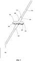
FIG. 1 depicts a medical device assembly including ananchor element 100 positioned on a medical device 102 (e.g., a distal portion of the medical device 102). Suchmedical devices 102 may include a diagnostic device, a monitoring device, a therapeutic device, or combinations thereof. For example, themedical device 102 may comprise a medical therapy delivery device, a medical device configured to sense a parameter of the subject, a medical device configured to diagnose a condition, a medical device configured to sample one or more tissues and/or fluids from a subject, or combinations thereof.- The
medical device 102 may be utilized alone to provide a medical service (e.g., diagnostic, monitoring, therapeutic, or combinations thereof) to a subject or may be utilized with one or more medical devices 103 (e.g., a medical device internal or external to the subject that is electrically and/or mechanically coupled to the medical device 102). For example, themedical device 102 and/ordevice 103 may comprise devices such as a pacemaker, defibrillator, monitoring device, infusion device, neurostimulator, gastric stimulator, cochlear device, or any other device that is at least partially subcutaneously implanted in a subject. - In some embodiments, at least a portion of the
medical device 102 is positioned proximate the nervous system of a subject (e.g., proximate the spinal cord or canal, brain, and/or peripheral nervous system). Themedical device 102 may be a catheter, a lead, or lead extension. For example, themedical device 102 may be a lead including one or more electrodes on a distal end portion of the lead. Electrical contacts in the lead may be electrically coupled (e.g., physically or wirelessly) to a control module having an electrical signal generator (e.g.,medical device 103 external or internal to the subject) and signals generated by themedical device 103 may be delivered to the subject via the electrodes. In some embodiments, such leads are utilized as implantable stimulation devices, which may be utilized in a variety of treatments and procedures, such as, for example, spinal cord stimulation. For example, implantable stimulation devices may be used to stimulate nerves, such as the spinal cord, muscles, or other tissue. The stimulator electrodes of the leads may be implanted in contact with or near the nerves, muscles, or other tissue to be stimulated. A pulse generator of themedical device 103 generates electrical pulses that are delivered by the electrodes to body tissue. In such embodiments, the lead is anchored at one or more places in the subject to prevent or reduce movement of the lead or stimulator electrodes within the subject (e.g., during short-term or long-term placement of thedevices medical device - As shown in
FIG. 1 , theanchor element 100 is placed over at least a portion of the medical device 102(e.g., a cannula of the medical device 102). For example, at least a portion of themedical device 102 may be positioned within a lumen formed by the tubular body (e.g., cannula) of theanchor element 100. As depicted, theanchor element 100 is shown in a deployed state where one or more protrusions (e.g., one, two, three, four, ormore lobes 104, e.g., circumferentially-spaced lobes) extend outwardly from a portion of the anchor element 100 (e.g., laterally outward from a longitudinal axis or centerline of the anchor element 100). Eachlobe 104 extending laterally from theanchor element 100 may form anopening 107 within thelobe 104. - When attached to the
medical device 102, thelobes 104 of theanchor element 100 may anchor themedical device 102 by engaging with one or more portions of the subject. For example, thelobes 104 of theanchor element 100 may engage with a portion of the subject's tissue (e.g., muscle tissue, nervous tissue, connective tissue,etc.) to at least partially retain themedical device 102 in a desired position within the subject. It is also believed that, in some embodiments, regrowth of the tissue of the subject proximate thelobes 104 may intertwine with at least a portion of the lobes 104 (e.g., tissue may extend through the openings 107) further anchoring theanchor element 100 andmedical device 102 within the subject. - The
anchor element 100 may be coupled (e.g., mechanically coupled) to at least a portion of the medical device 102 (e.g., an outer portion or exterior surface of the medical device 102). For example, theanchor element 100 may be secured to themedical device 102 through mechanical interference (e.g., utilizing friction, compression, swaging,etc.) rather than through adhesion or the use of fasteners. Theanchor element 100 may include one or more portions for retaining theanchor element 100 to themedical device 102. For example,engagement portions lobes 104 and may act to secure theanchor element 100 to the medical device 102 (e.g., via a mechanical interference fit). In some embodiments, each of theengagement portions anchor element 100 include an inner dimension (e.g., diameter) that is smaller than an outer dimension (e.g., diameter) of themedical device 102. One or more portions of the anchor element 100 (e.g.,engagement portions 106, 108) may be formed from a flexible material (e.g., an elastically deformable material) such as, for example, a polymer (e.g., silicone, polyurethane,etc.). Theflexible engagement portions engagement portions enlarged engagement portions medical device 102. As theenlarged engagement portions engagement portions medical device 102. - In some embodiments, one or more ends of the
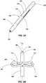
anchor element 100 include ataper 110 or chamfer to assist in insertion of theanchor element 100 into the subject. FIGS. 2A and 2B depict an anchor element (e.g., anchor element 100) in an initial state (e.g., a retracted or relaxed state) and a deployed state (e.g., a semi-distended state of the inner diameter), respectively. As shown inFIG. 2A , theanchor element 100 includes a protrusion orlobe portion 105 positioned between theengagement portions anchor element 100. The body of the anchor element may form alumen 101 therein. The lobes 104 (e.g., two lobes 104) of thelobe portion 105 are formed about the anchor element 100 (e.g., at equal circumferential spacing) byslits 112 in the tubular body of theanchor element 100. In the initial state, thelobe portion 105 of theanchor element 100 is substantially parallel to (e.g., coextensive with) a longitudinal axis L100 of theanchor element 100.- Referring also to
FIG. 2B , theengagement portions anchor element 100 to the deployed state. Theslits 112 enable thelobes 104 to extend outwardly (e.g., in a direction lateral or transverse (e.g., perpendicular) to the longitudinal axis L100 of the anchor element 100) from a portion of the anchor element 100 (e.g., from theengagement portions 106, 108). FIGS. 3A and 3B depict ananchor element 200 in an initial state (e.g., a retracted state) and a deployed state, respectively. As shown inFIG. 3A , theanchor element 200 may be somewhat similar toanchor element 100 discussed above and the body of theanchor element 200 may form alumen 201 therein. However,anchor element 200 may include more than one lobe portion (e.g., twolobe portions 205, 207) positioned between theengagement portions anchor element 200. In other embodiments, theanchor element 200 includes three, four, or more lobe portions. Lobes 204 (e.g., two lobes) of eachlobe portion slits 212 in the tubular body of theanchor element 200. In the initial state, thelobe portions 205 of theanchor element 200 are substantially parallel to (e.g., coextensive with) a longitudinal axis L200 of theanchor element 200.- In some embodiments, the
anchor element 200 includes anadditional engagement portion 209 positioned between thelobe portions - Referring also to
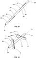
FIG. 3B , theengagement portions anchor element 200 to the deployed state. Theslits 212 enable thelobes 204 to extend outwardly (e.g., in a direction lateral or transverse (e.g., perpendicular) to a longitudinal axis L200 of the anchor element 200) from a portion of the anchor element 200 (e.g., from theengagement portions 206, 208). As depicted, thelobe portions FIG. 4 depicts ananchor deployment device 300 that may be utilized with an anchor element (e.g.,anchor elements FIGS. 1 through 3B ). As shown inFIG. 4 , theanchor deployment device 300 includes a first cannula (e.g., deployment cannula 302) and a second cannula (e.g., anchor cannula 304) received at least partially within thedeployment cannula 302. For example, thedeployment cannula 302 may have an inner dimension (e.g., diameter) that is greater than an outer dimension (e.g., diameter) of theanchor cannula 304 such that theanchor cannula 304 may be received and movable within thedeployment cannula 302. Theanchor deployment device 300 may include ahandle 306 having afirst portion 308 coupled to thedeployment cannula 302 and asecond portion 310 coupled to theanchor cannula 304. Theportions handle 310 may be movable relative to one another(e.g., thesecond portion 310 may slide relative to the first portion 308) in order to move theanchor cannula 304 within thedeployment cannula 302. Eachportion handle 306 may include one ormore grips 314 enabling a user (e.g., medical practitioner) to actuate thehandle 306, thereby sliding thesecond portion 310 relative to thefirst portion 308 along a common axis.- As depicted, the
anchor cannula 304 may be sized to receive an anchor element (e.g., anchor element 100) on theanchor cannula 304 atdistal portion 312 of theanchor deployment device 300. The outer dimension (e.g., diameter) of theanchor cannula 304 may be greater than the inner dimension (e.g., diameter) of theanchor element 100. Such a diameter of theanchor cannula 304 may act to enlarge a cross-sectional area of alumen 101 formed within a portion of the anchor element 100 (e.g., at each of theengagement portions 106, 108 (FIG. 1 )) to form an initial dimension to an enlarged dimension. For example, theanchor cannula 304 may deform (e.g., elastically deform) theanchor element 100 to a dimension (e.g., diameter) that is greater than a dimension (e.g., diameter) of the medical device 102 (FIG. 1 ) on which theanchor element 100 is to be placed. FIG. 5 depicts a view of theanchor deployment device 300 shown inFIG. 4 beginning to deploy an anchor element (e.g.,anchor element 100 in a distended state of the inner diameter). As shown inFIG. 5 , at least a portion of a medical device (e.g., medical device 102) may be received within a portion of theanchor deployment device 300. For example, theanchor cannula 304 may have an inner dimension (e.g., diameter) that is sized to enable at least a portion of themedical device 102 to be received within theanchor cannula 304. In some embodiments, aproximal portion 316 of theanchor deployment device 300 is configured such that themedical device 102 extends through theanchor deployment device 300 and out of the of theanchor deployment device 300 at theproximal portion 316. Such a configuration may enable a user to position theanchor deployment device 300 along and through themedical device 102 in order to secure ananchor element 100 to theanchor deployment device 300 at any desired position. For example, themedical device 102 may be placed within a subject and theanchor deployment device 300 may be slid along themedical device 102. A portion of the anchor deployment device 300 (e.g., the distal portion 312) may be inserted within the subject to secure theanchor element 100 within the subject while themedical device 102 resides within the subject.- Actuation of the
handle 306 may bring theanchor element 100, which is positioned on the anchor cannula 304 (e.g., in a radially enlarged or stretched state), into contact with the deployment cannula 302 (e.g., aleading end 318 of the deployment cannula 302). Thedeployment cannula 302 may act to force (e.g., slide) at least a portion of theanchor element 100 along theanchor cannula 304. For example, thedeployment cannula 302 may force thefirst engagement portion 106 toward thesecond engagement portion 108, thereby deploying thelobes 104 of theanchor element 100. As theanchor cannula 304 is slid within thedeployment cannula 302, theleading end 318 of thedeployment cannula 302 may force theanchor element 100 off of theanchor cannula 304 and onto the medical device 102 (e.g., into the position shown inFIG. 1 ). FIG. 6 depicts a cross-sectional view of a portion of theanchor deployment device 300 shown inFIG. 4 with themedical device 102 received in theanchor deployment device 300. As shown inFIG. 6 , the inner diameter ID304 of theanchor cannula 304 is sized to enable themedical device 102 to be received within theanchor cannula 304. The inner diameter ID302 of thedeployment cannula 302 may be greater than an outer dimension OD304 of theanchor cannula 304 such that theanchor cannula 304 may be received and movable within thedeployment cannula 302.FIG. 7 depicts another cross-sectional view of a portion of theanchor deployment device 300 shown inFIG. 4 with themedical device 102 received in theanchor deployment device 300 and theanchor element 100 attached to theanchor deployment device 300. The outer diameter OD304 of theanchor cannula 304 may be greater than an inner diameter of theanchor element 100 such that theanchor cannula 304 acts to enlarge a cross-sectional area of the lumen formed within a portion of theanchor element 100 to form an enlarged inner diameter ID100 of theanchor element 100 that is substantially equal to the outer diameter OD304 of theanchor cannula 304. The enlarged inner diameter ID100 of theanchor element 100 may be greater than an outer diameter OD102 of themedical device 102 such that the enlarged inner diameter ID100 of theanchor element 100 may be deployed over the outer diameter OD102 of themedical device 102. When theanchor element 100 is removed from the anchor cannula 304 (e.g., by thedeployment cannula 302 as discussed above), theanchor element 100 may contract toward the initial diameter to the anchor element 100 (e.g., where the initial diameter of theanchor element 100 is less than the outer diameter OD102 of the medical device 102) in order to secure theanchor element 100 to themedical device 102.FIGS. 8A and 8B depict ananchor element 400 in an initial state and a deployed state, respectively. Theanchor element 400 may be similar to and include one or more of the same features and functioning as theanchor elements FIGS. 1 through 3B . As shown inFIG. 8A , theanchor element 400 includes alobe portion 405 positioned between theengagement portions anchor element 400. The body of theanchor element 400 may form alumen 401 therein. Lobes 404 (e.g., two lobes) of thelobe portion 405 are formed about the anchor element 400 (e.g., at equal circumferential spacing) byslits 412 in the tubular body of theanchor element 400. In the initial state, thelobe portion 405 of theanchor element 400 is substantially parallel to (e.g., coextensive with) a longitudinal axis L400 of theanchor element 400.- Referring also to
FIG. 8B , theengagement portions anchor element 400 to the deployed state. Theslits 412 enable thelobes 404 to extend outwardly (e.g., in a direction lateral or transverse (e.g., perpendicular) to the longitudinal axis L400 of the anchor element 400) from a portion of the anchor element 400 (e.g., from theengagement portions 406, 408). - As depicted, the
anchor element 400 may include a biasing feature (e.g., a radial biasing feature). For example, theanchor element 400 may include one ormore springs 414 extending about at least a portion of the anchor element 400 (e.g., theengagement portions 406, 408). In some embodiments, thesprings 414 are disposed on an exterior portion of theanchor element 400. In other embodiments, thesprings 414 may be disposed within theanchor element 400. Thesprings 414 may act to bias theanchor element 400 in (e.g., toward) an initial state. For example, thesprings 414 may act to radially bias theengagement portions anchor element 400 inward in a direction toward the lumen 401 (e.g., constricting the lumen 401) such that thesprings 414 bias theengagement portions springs 414 act to relatively more rapidly tighten theanchor element 400 around a medical device 102 (see,e.g.,FIG. 5 ). - It is noted that any anchor element disclosed herein (e.g.,
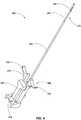
anchor elements 100, 200) may include a radial biasing feature (e.g., springs). In other embodiments, the anchor element may include an axial biasing feature. FIGS. 9 and 10 depict a perspective view and a side view, respectively, of ananchor deployment device 500. Theanchor deployment device 500 may be similar to and include one or more of the same features and functioning as theanchor deployment device 300 discussed above with reference toFIGS. 4 through 7 . As shown inFIGS. 9 and 10 , theanchor deployment device 500 includes a first cannula (e.g., deployment cannula 502) and a second cannula (e.g., anchor cannula 504) received at least partially within thedeployment cannula 502. Theanchor deployment device 500 may include a handle 506 (e.g., formed as a hub) coupled to theanchor cannula 504 such that thehandle 506 and theanchor cannula 504 may be moved relative to another portion of the anchor deployment device 500 (e.g., abody 501 of the anchor deployment device 500). For example, thebody 501 of theanchor deployment device 500 may define an opening orchamber 507 in which thehandle 506 is at least partially disposed. In some embodiments, thebody 501 of theanchor deployment device 500 defines atrack 509 in thechamber 507 upon which a portion of the handle 506 (e.g., a complementary portion) may move along (e.g., slide) to guide (e.g., and retain) thehandle 506 and theanchor cannula 504 relative to thebody 501 and thedeployment cannula 502. Movement of thehandle 506 relative to thebody 501 enables a user (e.g., medical practitioner) to slide theanchor cannula 504 relative to thedeployment cannula 502 along a common axis.- As depicted, the
anchor deployment device 500 is shown with an anchor element (e.g.,anchor element 400 in a distended state of the inner diameter) positioned on theanchor cannula 504 of theanchor deployment device 500. As above, theanchor deployment device 500 may have an inner dimension (e.g., diameter) that is sized to enable at least a portion of a medical device 102 (FIG. 5 ) to be received within theanchor cannula 504. As also described above, thehandle 506, theanchor cannula 504, and thedeployment cannula 502 may be utilized to deploy one or more anchor elements on a medical device (e.g.,anchor elements medical device 102 as shown and described above). - As further depicted in
FIGS. 9 and 10 , theanchor deployment device 500 may includeupper handle 510. A first end ofupper handle 510 may include alocking mechanism 512 that holds (e.g., locks, clamps,etc.) the medical device 102 (FIG. 5 ). For example, thelocking mechanism 512 may secure themedical device 102 when an anchor element is being deployed on the medical device 102 (e.g., when at least a portion of themedical device 102 is resident in a subject). - A second end of
upper handle 510 may include a protrusion orelongated member 514 that engages with thehandle 506 to secure thehandle 506 and theanchor cannula 504. For example, theelongated member 514 of theupper handle 510 may retain thehandle 506 and theanchor cannula 504 and prevent thehandle 506 and theanchor cannula 504 from sliding relative to thebody 501 ofanchor deployment device 500. - The
upper handle 510 may be configured such that the first end and the second end move (e.g., pivot) relative to each other. For example, when thelocking mechanism 512 is securing the medical device 102 (FIG. 5 ), theelongated member 514 is disengaged with thehandle 506, thereby enabling thehandle 506 and theanchor cannula 504 to move relative to thebody 501. Similarly, when theelongated member 514 is engaged with thehandle 506 and restricting thehandle 506 and theanchor cannula 504 from moving relative to thebody 501, thelocking mechanism 512 is disengaged from themedical device 102, thereby enabling theanchor deployment device 500 to move (e.g., slide) along themedical device 102. Such a configuration may enable theanchor deployment device 500 to be secured to themedical device 102 while an anchor element is being deployed and, likewise, secure theanchor deployment device 500 from any unwanted movement of theanchor cannula 504 relative to thedeployment cannula 502 when theanchor deployment device 500 is being moved and positioned along themedical device 102. - The
anchor deployment device 500 may includerear handle 516 that enables a user to move and position theanchor deployment device 500 along themedical device 102. - It is noted that to the extent that the anchor deployment devices are described in use with a particular anchor element, in other embodiments, the anchor deployment devices may be utilized with any suitable anchor element (e.g.,
anchor elements - It is further noted that while the anchor elements and components of the anchor deployment device are primarily discussed herein as having a diameter, these elements are not necessarily limited to circular cross sections. For example, the anchor elements and components of the anchor deployment device, and the lumens formed therein, may have a square, circular, oval, rectangular, or any other suitable cross-sectional shape.
- Referring to
FIGS. 1 through 10 , in operation, a lumen of an anchor element (e.g.,lumen anchor element anchor element anchor cannula 304 of theanchor deployment device 300. A medical device 102 (e.g., a medical device that has already been inserted and positioned within a subject) is positioned within theanchor element 302 and theanchor deployment device 300 andanchor element medical device 102 to position theanchor element anchor element handle 306 of theanchor deployment device 300 to deploy thelobes anchor element anchor element medical device 102 with thedeployment cannula 302. Constriction of theanchor element medical device 102 as theanchor element anchor element anchor element medical device 102 while both theanchor element medical device 102 are positioned within the subject. For example, theanchor element lumen anchor element lumen anchor element anchor element - Once the
anchor element medical device 102 within the subject, thelobes anchor element medical device 102 by engaging with one or more portions of the subject's tissue to at least partially retain themedical device 102 in a desired position within the subject. - Once being apprised of the instant disclosure, one of ordinary skill in the art will be able to make and use the devices and assemblies disclosed herein. For example, the anchor elements may be formed from a polymer (e.g., a polyurethane such as CARBOTHANE®) and springs may be formed from a metal material (e.g., 316 stainless steel).
- The scope of the invention is defined by the appended claims.
Claims (8)
- An anchor element assembly comprising:at least one anchor element having a longitudinal axis, the at least one anchor element comprising:two engagement portions for securing to at least a portion of a medical device;at least one lobe section positioned between the two engagement portions and comprising at least one lobe configured to extend transversely from the longitudinal axis of the at least one anchor element when the at least one anchor element is in a deployed state; anda lumen formed within the at least one anchor element configured to receive at least a portion of a medical device in the lumen; andan anchor deployment device comprising:a first cannula configured to receive the at least one anchor element thereon; anda second cannula having at least a portion of the first cannula received therein,wherein the first cannula is movable relative to the second cannula, andwherein the second cannula and the at least one anchor element are mutually configured to:force the two engagement portions toward each other in order to extend the at least one lobe section to position the at least one anchor element in the deployed state while the at least one anchor element is positioned on the first cannula; andforce the at least one anchor element off of the first cannula in the deployed state in order to secure the at least one anchor element to the at least a portion of the medical device in the deployed state;wherein an outer dimension of the first cannula of the anchor deployment device is greater than an inner dimension of the at least one anchor element, the first cannula configured to at least partially enlarge the lumen of the at least one anchor element in order to deploy the at least one anchor element over the at least a portion of the medical device;wherein an inner dimension of the first cannula of the anchor deployment device is greater than an outer dimension of the at least a portion of the medical device, the first cannula configured to receive at least a portion of the medical device within a lumen formed within the first cannula; andwherein the lumen of the at least one anchor element is configured to contract around the at least a portion of the medical device in order to secure the at least one anchor element to the at least a portion of the medical device.
- The anchor element assembly of claim 1, wherein the first cannula is coupled to a hub movably received within a portion of the anchor deployment device such that movement of the hub translates the first cannula relative to the second cannula.
- The anchor element assembly of claim 2, wherein the anchor deployment device further comprises a securing member configured to secure the hub to the anchor deployment device to prevent movement of the hub and the first cannula relative to the second cannula.
- The anchor element assembly of claim 1 or 3, wherein the anchor deployment device further comprises a locking mechanism configured to secure the medical device to the anchor deployment device.
- The anchor element assembly of claim 4, wherein the anchor deployment device further comprises a pivoting handle having the locking mechanism on a first side of the pivoting handle and the securing member on a second side of the pivoting handle, wherein, in a first position of the pivoting handle, the locking mechanism is configured to be engaged with the medical device and disengaged from the hub and, in a second position of the pivoting handle, the locking mechanism is configured to be disengaged from the medical device and engaged with the hub.
- The anchor element assembly of any one of claims 1 through 4, wherein the anchor deployment device is configured to at least partially move the at least one anchor element from an initial state where the at least one lobe section of the at least one anchor element is substantially parallel to the longitudinal axis of the at least one anchor element to the deployed state where the at least one lobe of the at least one lobe section extends transversely from the longitudinal axis of the at least one anchor element.
- The anchor element assembly of any one of claims 1 through 4, wherein the at least one lobe section of the at least one anchor element comprises at least two lobe sections spaced along the longitudinal axis of the at least one anchor element, each lobe section of the at least two lobe sections comprising at least two lobes.
- The anchor element assembly of claim 7, wherein the at least two lobes of a first lobe section of the at least two lobe sections are offset about the longitudinal axis of the at least one anchor element from the at least two lobes of a second lobe section of the at least two lobe sections.
Applications Claiming Priority (2)
| Application Number | Priority Date | Filing Date | Title |
|---|---|---|---|
| US201361908603P | 2013-11-25 | 2013-11-25 | |
| PCT/US2014/067500WO2015077796A1 (en) | 2013-11-25 | 2014-11-25 | Anchor elements, medical devices including one or more anchor elements and related assemblies and methods |
Publications (3)
| Publication Number | Publication Date |
|---|---|
| EP3074084A1 EP3074084A1 (en) | 2016-10-05 |
| EP3074084A4 EP3074084A4 (en) | 2017-08-30 |
| EP3074084B1true EP3074084B1 (en) | 2019-10-30 |
Family
ID=53180315
Family Applications (1)
| Application Number | Title | Priority Date | Filing Date |
|---|---|---|---|
| EP14863371.2AActiveEP3074084B1 (en) | 2013-11-25 | 2014-11-25 | Anchor element deployment assembly for medical devices |
Country Status (9)
| Country | Link |
|---|---|
| US (2) | US10226620B2 (en) |
| EP (1) | EP3074084B1 (en) |
| JP (1) | JP6697393B2 (en) |
| KR (1) | KR102407167B1 (en) |
| CN (1) | CN105813689B (en) |
| AU (1) | AU2014352645B2 (en) |
| CA (1) | CA2931459C (en) |
| ES (1) | ES2765303T3 (en) |
| WO (1) | WO2015077796A1 (en) |
Families Citing this family (9)
| Publication number | Priority date | Publication date | Assignee | Title |
|---|---|---|---|---|
| CN105813689B (en) | 2013-11-25 | 2019-06-25 | 定制医学应用有限公司 | Anchoring element, the medical device including one or more anchoring elements and associated component and method |
| US10448972B2 (en) | 2015-09-15 | 2019-10-22 | Custom Medical Applications Inc. | Deployment devices and related assemblies and methods |
| EP3648679A4 (en)* | 2017-07-10 | 2021-03-31 | Stimwave Technologies Incorporated | An injectable anchor system and methods for using the same to implant an implantable device |
| CN108553697B (en)* | 2018-04-25 | 2021-01-15 | 刘晓君 | Special drainage nursing device of hepatobiliary surgery |
| JP7524528B2 (en)* | 2019-10-16 | 2024-07-30 | 住友ベークライト株式会社 | Medical Expanders |
| CN211835836U (en)* | 2019-10-31 | 2020-11-03 | 杭州神络医疗科技有限公司 | Electrode anchor mounting device |
| US11524155B2 (en)* | 2020-05-01 | 2022-12-13 | Advanced Neuromodulation Systems, Inc. | Foraminal ligament anchor for application in DRG therapy |
| CN112426571A (en)* | 2020-11-12 | 2021-03-02 | 自贡市第四人民医院(自贡市急救中心) | Drainage and fixing device of semifluid secretion |
| USD1042810S1 (en)* | 2022-05-26 | 2024-09-17 | Koumpi LLC | Endotracheal intubation device |
Family Cites Families (60)
| Publication number | Priority date | Publication date | Assignee | Title |
|---|---|---|---|---|
| FR779080A (en)* | 1934-09-17 | 1935-03-29 | New method and machine for <<corroyer>> and <<smooth>> cuts of soles and leather | |
| US3397699A (en) | 1966-05-05 | 1968-08-20 | Gerald C. Kohl | Retaining catheter having resiliently biased wing flanges |
| US4374527A (en) | 1978-07-19 | 1983-02-22 | Medtronic, Inc. | Body stimulation lead |
| US4406042A (en) | 1981-04-13 | 1983-09-27 | American Hospital Supply Corporation | Tubing clip |
| US4419819A (en)* | 1982-01-29 | 1983-12-13 | Medtronic, Inc. | Method of making biomedical lead with lobed lead anchor |
| US4913164A (en) | 1988-09-27 | 1990-04-03 | Intermedics, Inc. | Extensible passive fixation mechanism for lead assembly of an implantable cardiac stimulator |
| US5238007A (en) | 1991-12-12 | 1993-08-24 | Vitatron Medical B.V. | Pacing lead with improved anchor mechanism |
| US5344439A (en) | 1992-10-30 | 1994-09-06 | Medtronic, Inc. | Catheter with retractable anchor mechanism |
| US5584874A (en) | 1995-04-28 | 1996-12-17 | Medtronic, Inc. | Medical electrical lead having improved anchoring sleeve |
| US5658309A (en) | 1995-05-01 | 1997-08-19 | C. R. Bard, Inc. | Guidewire/inflation tube locking apparatus and method of use |
| FR2742058B1 (en)* | 1995-12-12 | 1998-03-06 | Ela Medical Sa | FOLDABLE ANCHOR BARS PROBES FOR AN IMPLANTED MEDICAL DEVICE, IN PARTICULAR FOR A HEART STIMULATOR |
| DE29601310U1 (en) | 1996-01-26 | 1997-06-05 | B. Braun Melsungen Ag, 34212 Melsungen | Catheter set with ECG lead possibility |
| EP1039864B1 (en)* | 1997-11-14 | 2006-12-27 | Boston Scientific Limited | Multi-sheath delivery catheter |
| US20010021824A1 (en) | 1998-07-17 | 2001-09-13 | Marsh Ronald W. | Variable extension combined spinal/epidural needle set and method for its use |
| DE19928901C2 (en) | 1999-06-24 | 2003-06-05 | Vasco Med Inst Fuer Katheterte | Device for pulling an object having an elongated inner lumen out of its anchoring in a body |
| US6473654B1 (en) | 2000-03-08 | 2002-10-29 | Advanced Bionics Corporation | Lead anchor |
| US6517573B1 (en) | 2000-04-11 | 2003-02-11 | Endovascular Technologies, Inc. | Hook for attaching to a corporeal lumen and method of manufacturing |
| US6901287B2 (en) | 2001-02-09 | 2005-05-31 | Medtronic, Inc. | Implantable therapy delivery element adjustable anchor |
| US6620122B2 (en)* | 2001-04-26 | 2003-09-16 | Scimed Life Systems, Inc. | Gastric pseudocyst drainage and stent delivery system for use therein |
| US20030199961A1 (en)* | 2002-04-03 | 2003-10-23 | Bjorklund Vicki L. | Method and apparatus for fixating a pacing lead of an implantable medical device |
| US20030199831A1 (en) | 2002-04-23 | 2003-10-23 | Morris Mary M. | Catheter anchor system and method |
| WO2004028348A2 (en) | 2002-09-26 | 2004-04-08 | Savacor, Inc. | Cardiovascular anchoring device and method of deploying same |
| US8303511B2 (en) | 2002-09-26 | 2012-11-06 | Pacesetter, Inc. | Implantable pressure transducer system optimized for reduced thrombosis effect |
| US7317951B2 (en)* | 2003-07-25 | 2008-01-08 | Integrated Sensing Systems, Inc. | Anchor for medical implant placement and method of manufacture |
| US7056286B2 (en) | 2003-11-12 | 2006-06-06 | Adrian Ravenscroft | Medical device anchor and delivery system |
| US7452351B2 (en)* | 2004-04-16 | 2008-11-18 | Kyphon Sarl | Spinal diagnostic methods and apparatus |
| USD531724S1 (en) | 2004-07-29 | 2006-11-07 | The Gessert Group | Physician demonstration tool |
| US8118749B2 (en) | 2005-03-03 | 2012-02-21 | Cardiomems, Inc. | Apparatus and method for sensor deployment and fixation |
| US7591970B2 (en) | 2005-03-07 | 2009-09-22 | Medtronic, Inc. | Medical device anchor and method of manufacture thereof |
| US7811251B2 (en) | 2005-10-13 | 2010-10-12 | Tyco Healthcare Group Lp | Trocar anchor |
| US8016794B2 (en) | 2006-03-09 | 2011-09-13 | Interrad Medical, Inc. | Anchor device and method |
| US8298281B2 (en) | 2006-07-18 | 2012-10-30 | Cordis Corporation | Twisted anchoring barb for stent of abdominal aortic aneurysm (AAA) device |
| US7731132B2 (en) | 2006-08-31 | 2010-06-08 | Fricker/Raines/Sinnott, Llc | Medication fluid tube stabilization device |
| US7765015B2 (en) | 2007-01-12 | 2010-07-27 | Cardiac Pacemakers, Inc. | Lead with inflatable fixation mechanism |
| JP5562648B2 (en)* | 2007-01-29 | 2014-07-30 | スパイナル・モデュレーション・インコーポレイテッド | Non-stitched top retaining mechanism |
| US20120071833A1 (en) | 2007-03-02 | 2012-03-22 | Hill Roger J | Implantable catheter or lead anchor for implantable medical device system and method of use |
| EP2150187A2 (en) | 2007-04-18 | 2010-02-10 | Access Scientific, Inc. | Access device |
| US7753889B2 (en) | 2007-06-15 | 2010-07-13 | Interrad Medical, Inc. | Anchor instrumentation and methods |
| US20090105746A1 (en) | 2007-10-17 | 2009-04-23 | Gardia Medical Ltd | Guidewire stop |
| US8343029B2 (en) | 2007-10-24 | 2013-01-01 | Circulite, Inc. | Transseptal cannula, tip, delivery system, and method |
| US8262624B2 (en)* | 2008-03-27 | 2012-09-11 | Medtronic, Inc. | Anchor and anchor deployment apparatus |
| US8235948B2 (en) | 2008-06-27 | 2012-08-07 | Interrad Medical, Inc. | System for anchoring medical devices |
| US8038653B2 (en) | 2008-07-16 | 2011-10-18 | Interrad Medical, Inc. | Anchor systems and methods |
| US7908015B2 (en) | 2008-07-31 | 2011-03-15 | Medtronic, Inc. | Subcutaneously implantable lead including distal fixation mechanism |
| US8029476B2 (en)* | 2008-11-19 | 2011-10-04 | Interrad Medical, Inc. | Anchoring a medical instrument |
| US8317827B2 (en) | 2009-01-07 | 2012-11-27 | Ethicon Endo-Surgery, Inc. | Suturing devices and methods |
| WO2010085456A1 (en) | 2009-01-20 | 2010-07-29 | Guided Delivery Systems Inc. | Anchor deployment devices and related methods |
| US8295948B2 (en) | 2009-07-21 | 2012-10-23 | Boston Scientific Neuromodulation Corporation | Tubular lead anchor and methods and devices using the anchor |
| US8311643B2 (en) | 2009-07-21 | 2012-11-13 | North Richard B | Spinal cord stimulation lead anchor |
| US8229573B2 (en) | 2009-07-21 | 2012-07-24 | Boston Scientific Neuromodulation Corporation | Spring passive lead anchor and methods and devices using the anchor |
| US8740972B2 (en) | 2009-12-22 | 2014-06-03 | Cook Medical Technologies Llc | Medical device with anchor members |
| US10105224B2 (en) | 2010-09-01 | 2018-10-23 | Mvalve Technologies Ltd. | Cardiac valve support structure |
| US9498248B2 (en) | 2010-10-05 | 2016-11-22 | Medtronic, Inc. | Retainer for immobilizing an implanted catheter during stylet retraction, and stylet holder for use with same |
| EP2788073B1 (en)* | 2011-11-10 | 2018-03-21 | Medtronic Inc. | Introduction and anchoring tool for an implantable medical device element |
| USD718436S1 (en) | 2012-10-26 | 2014-11-25 | Beyondevices Lda | Apparatus and equipment for delivering medication to a patient |
| US9198650B2 (en) | 2012-12-27 | 2015-12-01 | Medos International Sarl | Multi-piece anchor inserter |
| US9302043B2 (en) | 2013-03-12 | 2016-04-05 | Medtronic, Inc. | Socketed portal anchors and methods of using same |
| USD709753S1 (en) | 2013-05-23 | 2014-07-29 | Industrie Borla, S.P.A. | Locking cannula |
| CN105813689B (en) | 2013-11-25 | 2019-06-25 | 定制医学应用有限公司 | Anchoring element, the medical device including one or more anchoring elements and associated component and method |
| USD785793S1 (en) | 2016-06-14 | 2017-05-02 | Landanger | Device for mitral prosthesis rope laying |
- 2014
- 2014-11-25CNCN201480068715.9Apatent/CN105813689B/enactiveActive
- 2014-11-25KRKR1020167016693Apatent/KR102407167B1/enactiveActive
- 2014-11-25WOPCT/US2014/067500patent/WO2015077796A1/enactiveApplication Filing
- 2014-11-25EPEP14863371.2Apatent/EP3074084B1/enactiveActive
- 2014-11-25USUS15/039,027patent/US10226620B2/enactiveActive
- 2014-11-25AUAU2014352645Apatent/AU2014352645B2/enactiveActive
- 2014-11-25JPJP2016554835Apatent/JP6697393B2/enactiveActive
- 2014-11-25ESES14863371Tpatent/ES2765303T3/enactiveActive
- 2014-11-25CACA2931459Apatent/CA2931459C/enactiveActive
- 2016
- 2016-11-16USUS29/584,674patent/USD865165S1/enactiveActive
Non-Patent Citations (1)
| Title |
|---|
| None* |
Also Published As
| Publication number | Publication date |
|---|---|
| CN105813689A (en) | 2016-07-27 |
| KR20160118220A (en) | 2016-10-11 |
| USD865165S1 (en) | 2019-10-29 |
| JP6697393B2 (en) | 2020-05-20 |
| CA2931459A1 (en) | 2015-05-28 |
| US10226620B2 (en) | 2019-03-12 |
| KR102407167B1 (en) | 2022-06-10 |
| JP2016537179A (en) | 2016-12-01 |
| AU2014352645A1 (en) | 2016-07-07 |
| EP3074084A1 (en) | 2016-10-05 |
| EP3074084A4 (en) | 2017-08-30 |
| US20170165478A1 (en) | 2017-06-15 |
| AU2014352645B2 (en) | 2019-05-30 |
| CN105813689B (en) | 2019-06-25 |
| WO2015077796A1 (en) | 2015-05-28 |
| ES2765303T3 (en) | 2020-06-08 |
| CA2931459C (en) | 2022-11-22 |
Similar Documents
| Publication | Publication Date | Title |
|---|---|---|
| EP3074084B1 (en) | Anchor element deployment assembly for medical devices | |
| US8483845B2 (en) | Anchor for implantable medical device | |
| US8676341B2 (en) | Multi durometer reinforced suture sleeve | |
| US8613729B2 (en) | Anchor and anchor deployment apparatus | |
| US11918250B2 (en) | Deployment devices and related methods | |
| EP2667928B1 (en) | Repositionable therapy delivery element anchor | |
| HK1224975A1 (en) | Anchor elements, medical devices including one or more anchor elements and related assemblies and methods | |
| HK1224975B (en) | Anchor elements, medical devices including one or more anchor elements and related assemblies and methods |
Legal Events
| Date | Code | Title | Description |
|---|---|---|---|
| PUAI | Public reference made under article 153(3) epc to a published international application that has entered the european phase | Free format text:ORIGINAL CODE: 0009012 | |
| 17P | Request for examination filed | Effective date:20160620 | |
| AK | Designated contracting states | Kind code of ref document:A1 Designated state(s):AL AT BE BG CH CY CZ DE DK EE ES FI FR GB GR HR HU IE IS IT LI LT LU LV MC MK MT NL NO PL PT RO RS SE SI SK SM TR | |
| AX | Request for extension of the european patent | Extension state:BA ME | |
| DAX | Request for extension of the european patent (deleted) | ||
| A4 | Supplementary search report drawn up and despatched | Effective date:20170727 | |
| RIC1 | Information provided on ipc code assigned before grant | Ipc:A61M 25/04 20060101ALI20170721BHEP Ipc:A61N 1/05 20060101AFI20170721BHEP Ipc:A61B 5/00 20060101ALN20170721BHEP Ipc:A61B 17/34 20060101ALN20170721BHEP | |
| STAA | Information on the status of an ep patent application or granted ep patent | Free format text:STATUS: EXAMINATION IS IN PROGRESS | |
| 17Q | First examination report despatched | Effective date:20181114 | |
| REG | Reference to a national code | Ref country code:DE Ref legal event code:R079 Ref document number:602014056085 Country of ref document:DE Free format text:PREVIOUS MAIN CLASS: A61N0001362000 Ipc:A61N0001050000 | |
| GRAP | Despatch of communication of intention to grant a patent | Free format text:ORIGINAL CODE: EPIDOSNIGR1 | |
| STAA | Information on the status of an ep patent application or granted ep patent | Free format text:STATUS: GRANT OF PATENT IS INTENDED | |
| RIC1 | Information provided on ipc code assigned before grant | Ipc:A61B 17/34 20060101ALN20190426BHEP Ipc:A61B 17/04 20060101ALI20190426BHEP Ipc:A61N 1/05 20060101AFI20190426BHEP Ipc:A61M 25/04 20060101ALI20190426BHEP Ipc:A61B 5/00 20060101ALN20190426BHEP Ipc:A61M 25/02 20060101ALI20190426BHEP | |
| RIC1 | Information provided on ipc code assigned before grant | Ipc:A61B 17/34 20060101ALN20190508BHEP Ipc:A61B 5/00 20060101ALN20190508BHEP Ipc:A61B 17/04 20060101ALI20190508BHEP Ipc:A61M 25/02 20060101ALI20190508BHEP Ipc:A61N 1/05 20060101AFI20190508BHEP Ipc:A61M 25/04 20060101ALI20190508BHEP | |
| INTG | Intention to grant announced | Effective date:20190527 | |
| GRAS | Grant fee paid | Free format text:ORIGINAL CODE: EPIDOSNIGR3 | |
| GRAA | (expected) grant | Free format text:ORIGINAL CODE: 0009210 | |
| STAA | Information on the status of an ep patent application or granted ep patent | Free format text:STATUS: THE PATENT HAS BEEN GRANTED | |
| AK | Designated contracting states | Kind code of ref document:B1 Designated state(s):AL AT BE BG CH CY CZ DE DK EE ES FI FR GB GR HR HU IE IS IT LI LT LU LV MC MK MT NL NO PL PT RO RS SE SI SK SM TR | |
| REG | Reference to a national code | Ref country code:GB Ref legal event code:FG4D | |
| REG | Reference to a national code | Ref country code:CH Ref legal event code:EP | |
| REG | Reference to a national code | Ref country code:AT Ref legal event code:REF Ref document number:1195507 Country of ref document:AT Kind code of ref document:T Effective date:20191115 | |
| REG | Reference to a national code | Ref country code:DE Ref legal event code:R096 Ref document number:602014056085 Country of ref document:DE | |
| REG | Reference to a national code | Ref country code:IE Ref legal event code:FG4D | |
| REG | Reference to a national code | Ref country code:LT Ref legal event code:MG4D | |
| PG25 | Lapsed in a contracting state [announced via postgrant information from national office to epo] | Ref country code:PL Free format text:LAPSE BECAUSE OF FAILURE TO SUBMIT A TRANSLATION OF THE DESCRIPTION OR TO PAY THE FEE WITHIN THE PRESCRIBED TIME-LIMIT Effective date:20191030 Ref country code:GR Free format text:LAPSE BECAUSE OF FAILURE TO SUBMIT A TRANSLATION OF THE DESCRIPTION OR TO PAY THE FEE WITHIN THE PRESCRIBED TIME-LIMIT Effective date:20200131 Ref country code:LT Free format text:LAPSE BECAUSE OF FAILURE TO SUBMIT A TRANSLATION OF THE DESCRIPTION OR TO PAY THE FEE WITHIN THE PRESCRIBED TIME-LIMIT Effective date:20191030 Ref country code:PT Free format text:LAPSE BECAUSE OF FAILURE TO SUBMIT A TRANSLATION OF THE DESCRIPTION OR TO PAY THE FEE WITHIN THE PRESCRIBED TIME-LIMIT Effective date:20200302 Ref country code:BG Free format text:LAPSE BECAUSE OF FAILURE TO SUBMIT A TRANSLATION OF THE DESCRIPTION OR TO PAY THE FEE WITHIN THE PRESCRIBED TIME-LIMIT Effective date:20200130 Ref country code:NO Free format text:LAPSE BECAUSE OF FAILURE TO SUBMIT A TRANSLATION OF THE DESCRIPTION OR TO PAY THE FEE WITHIN THE PRESCRIBED TIME-LIMIT Effective date:20200130 Ref country code:FI Free format text:LAPSE BECAUSE OF FAILURE TO SUBMIT A TRANSLATION OF THE DESCRIPTION OR TO PAY THE FEE WITHIN THE PRESCRIBED TIME-LIMIT Effective date:20191030 Ref country code:LV Free format text:LAPSE BECAUSE OF FAILURE TO SUBMIT A TRANSLATION OF THE DESCRIPTION OR TO PAY THE FEE WITHIN THE PRESCRIBED TIME-LIMIT Effective date:20191030 Ref country code:SE Free format text:LAPSE BECAUSE OF FAILURE TO SUBMIT A TRANSLATION OF THE DESCRIPTION OR TO PAY THE FEE WITHIN THE PRESCRIBED TIME-LIMIT Effective date:20191030 | |
| REG | Reference to a national code | Ref country code:NL Ref legal event code:FP | |
| PG25 | Lapsed in a contracting state [announced via postgrant information from national office to epo] | Ref country code:HR Free format text:LAPSE BECAUSE OF FAILURE TO SUBMIT A TRANSLATION OF THE DESCRIPTION OR TO PAY THE FEE WITHIN THE PRESCRIBED TIME-LIMIT Effective date:20191030 Ref country code:IS Free format text:LAPSE BECAUSE OF FAILURE TO SUBMIT A TRANSLATION OF THE DESCRIPTION OR TO PAY THE FEE WITHIN THE PRESCRIBED TIME-LIMIT Effective date:20200229 Ref country code:RS Free format text:LAPSE BECAUSE OF FAILURE TO SUBMIT A TRANSLATION OF THE DESCRIPTION OR TO PAY THE FEE WITHIN THE PRESCRIBED TIME-LIMIT Effective date:20191030 | |
| REG | Reference to a national code | Ref country code:ES Ref legal event code:FG2A Ref document number:2765303 Country of ref document:ES Kind code of ref document:T3 Effective date:20200608 | |
| PG25 | Lapsed in a contracting state [announced via postgrant information from national office to epo] | Ref country code:AL Free format text:LAPSE BECAUSE OF FAILURE TO SUBMIT A TRANSLATION OF THE DESCRIPTION OR TO PAY THE FEE WITHIN THE PRESCRIBED TIME-LIMIT Effective date:20191030 | |
| REG | Reference to a national code | Ref country code:CH Ref legal event code:PL | |
| PG25 | Lapsed in a contracting state [announced via postgrant information from national office to epo] | Ref country code:CZ Free format text:LAPSE BECAUSE OF FAILURE TO SUBMIT A TRANSLATION OF THE DESCRIPTION OR TO PAY THE FEE WITHIN THE PRESCRIBED TIME-LIMIT Effective date:20191030 Ref country code:RO Free format text:LAPSE BECAUSE OF FAILURE TO SUBMIT A TRANSLATION OF THE DESCRIPTION OR TO PAY THE FEE WITHIN THE PRESCRIBED TIME-LIMIT Effective date:20191030 Ref country code:MC Free format text:LAPSE BECAUSE OF FAILURE TO SUBMIT A TRANSLATION OF THE DESCRIPTION OR TO PAY THE FEE WITHIN THE PRESCRIBED TIME-LIMIT Effective date:20191030 Ref country code:LU Free format text:LAPSE BECAUSE OF NON-PAYMENT OF DUE FEES Effective date:20191125 Ref country code:DK Free format text:LAPSE BECAUSE OF FAILURE TO SUBMIT A TRANSLATION OF THE DESCRIPTION OR TO PAY THE FEE WITHIN THE PRESCRIBED TIME-LIMIT Effective date:20191030 Ref country code:LI Free format text:LAPSE BECAUSE OF NON-PAYMENT OF DUE FEES Effective date:20191130 Ref country code:EE Free format text:LAPSE BECAUSE OF FAILURE TO SUBMIT A TRANSLATION OF THE DESCRIPTION OR TO PAY THE FEE WITHIN THE PRESCRIBED TIME-LIMIT Effective date:20191030 Ref country code:CH Free format text:LAPSE BECAUSE OF NON-PAYMENT OF DUE FEES Effective date:20191130 | |
| REG | Reference to a national code | Ref country code:DE Ref legal event code:R097 Ref document number:602014056085 Country of ref document:DE | |
| REG | Reference to a national code | Ref country code:AT Ref legal event code:MK05 Ref document number:1195507 Country of ref document:AT Kind code of ref document:T Effective date:20191030 | |
| PG25 | Lapsed in a contracting state [announced via postgrant information from national office to epo] | Ref country code:SK Free format text:LAPSE BECAUSE OF FAILURE TO SUBMIT A TRANSLATION OF THE DESCRIPTION OR TO PAY THE FEE WITHIN THE PRESCRIBED TIME-LIMIT Effective date:20191030 Ref country code:SM Free format text:LAPSE BECAUSE OF FAILURE TO SUBMIT A TRANSLATION OF THE DESCRIPTION OR TO PAY THE FEE WITHIN THE PRESCRIBED TIME-LIMIT Effective date:20191030 | |
| PLBE | No opposition filed within time limit | Free format text:ORIGINAL CODE: 0009261 | |
| STAA | Information on the status of an ep patent application or granted ep patent | Free format text:STATUS: NO OPPOSITION FILED WITHIN TIME LIMIT | |
| 26N | No opposition filed | Effective date:20200731 | |
| PG25 | Lapsed in a contracting state [announced via postgrant information from national office to epo] | Ref country code:SI Free format text:LAPSE BECAUSE OF FAILURE TO SUBMIT A TRANSLATION OF THE DESCRIPTION OR TO PAY THE FEE WITHIN THE PRESCRIBED TIME-LIMIT Effective date:20191030 Ref country code:AT Free format text:LAPSE BECAUSE OF FAILURE TO SUBMIT A TRANSLATION OF THE DESCRIPTION OR TO PAY THE FEE WITHIN THE PRESCRIBED TIME-LIMIT Effective date:20191030 | |
| PG25 | Lapsed in a contracting state [announced via postgrant information from national office to epo] | Ref country code:CY Free format text:LAPSE BECAUSE OF FAILURE TO SUBMIT A TRANSLATION OF THE DESCRIPTION OR TO PAY THE FEE WITHIN THE PRESCRIBED TIME-LIMIT Effective date:20191030 | |
| PG25 | Lapsed in a contracting state [announced via postgrant information from national office to epo] | Ref country code:HU Free format text:LAPSE BECAUSE OF FAILURE TO SUBMIT A TRANSLATION OF THE DESCRIPTION OR TO PAY THE FEE WITHIN THE PRESCRIBED TIME-LIMIT; INVALID AB INITIO Effective date:20141125 Ref country code:MT Free format text:LAPSE BECAUSE OF FAILURE TO SUBMIT A TRANSLATION OF THE DESCRIPTION OR TO PAY THE FEE WITHIN THE PRESCRIBED TIME-LIMIT Effective date:20191030 | |
| PG25 | Lapsed in a contracting state [announced via postgrant information from national office to epo] | Ref country code:TR Free format text:LAPSE BECAUSE OF FAILURE TO SUBMIT A TRANSLATION OF THE DESCRIPTION OR TO PAY THE FEE WITHIN THE PRESCRIBED TIME-LIMIT Effective date:20191030 | |
| PG25 | Lapsed in a contracting state [announced via postgrant information from national office to epo] | Ref country code:MK Free format text:LAPSE BECAUSE OF FAILURE TO SUBMIT A TRANSLATION OF THE DESCRIPTION OR TO PAY THE FEE WITHIN THE PRESCRIBED TIME-LIMIT Effective date:20191030 | |
| PGFP | Annual fee paid to national office [announced via postgrant information from national office to epo] | Ref country code:NL Payment date:20241126 Year of fee payment:11 | |
| PGFP | Annual fee paid to national office [announced via postgrant information from national office to epo] | Ref country code:DE Payment date:20241127 Year of fee payment:11 | |
| PGFP | Annual fee paid to national office [announced via postgrant information from national office to epo] | Ref country code:BE Payment date:20241127 Year of fee payment:11 | |
| PGFP | Annual fee paid to national office [announced via postgrant information from national office to epo] | Ref country code:GB Payment date:20241127 Year of fee payment:11 | |
| PGFP | Annual fee paid to national office [announced via postgrant information from national office to epo] | Ref country code:FR Payment date:20241128 Year of fee payment:11 | |
| PGFP | Annual fee paid to national office [announced via postgrant information from national office to epo] | Ref country code:IE Payment date:20241127 Year of fee payment:11 | |
| PGFP | Annual fee paid to national office [announced via postgrant information from national office to epo] | Ref country code:IT Payment date:20241122 Year of fee payment:11 Ref country code:ES Payment date:20241202 Year of fee payment:11 |