EP3073942B1 - Features to apply fluid to an ultrasonic blade of a surgical instrument - Google Patents
Features to apply fluid to an ultrasonic blade of a surgical instrumentDownload PDFInfo
- Publication number
- EP3073942B1 EP3073942B1EP14816508.7AEP14816508AEP3073942B1EP 3073942 B1EP3073942 B1EP 3073942B1EP 14816508 AEP14816508 AEP 14816508AEP 3073942 B1EP3073942 B1EP 3073942B1
- Authority
- EP
- European Patent Office
- Prior art keywords
- clamp arm
- ultrasonic blade
- pad
- blade
- ultrasonic
- Prior art date
- Legal status (The legal status is an assumption and is not a legal conclusion. Google has not performed a legal analysis and makes no representation as to the accuracy of the status listed.)
- Active
Links
- 239000012530fluidSubstances0.000titleclaimsdescription26
- 239000012636effectorSubstances0.000claimsdescription42
- 239000012809cooling fluidSubstances0.000claimsdescription16
- 229920006395saturated elastomerPolymers0.000claimsdescription10
- 238000004891communicationMethods0.000claimsdescription6
- 239000006261foam materialSubstances0.000claimsdescription4
- 230000009471actionEffects0.000claimsdescription3
- 238000009736wettingMethods0.000claims23
- 238000001816coolingMethods0.000description19
- 238000001356surgical procedureMethods0.000description16
- 238000005516engineering processMethods0.000description15
- 238000000576coating methodMethods0.000description12
- 238000000034methodMethods0.000description11
- 239000011248coating agentSubstances0.000description10
- 239000007788liquidSubstances0.000description8
- 210000003813thumbAnatomy0.000description8
- 230000004888barrier functionEffects0.000description7
- 238000005520cutting processMethods0.000description7
- 210000003811fingerAnatomy0.000description7
- FAPWRFPIFSIZLT-UHFFFAOYSA-MSodium chlorideChemical compound[Na+].[Cl-]FAPWRFPIFSIZLT-UHFFFAOYSA-M0.000description6
- 239000000090biomarkerSubstances0.000description6
- 239000003814drugSubstances0.000description6
- 239000000463materialSubstances0.000description6
- 239000011780sodium chlorideSubstances0.000description6
- 229940124597therapeutic agentDrugs0.000description6
- 238000010438heat treatmentMethods0.000description5
- 239000012212insulatorSubstances0.000description5
- 230000003213activating effectEffects0.000description4
- 230000001112coagulating effectEffects0.000description4
- 230000010355oscillationEffects0.000description4
- 230000005855radiationEffects0.000description4
- 238000013519translationMethods0.000description4
- 238000004140cleaningMethods0.000description3
- 230000014509gene expressionEffects0.000description3
- 108090000623proteins and genesProteins0.000description3
- 102000004169proteins and genesHuman genes0.000description3
- GWEVSGVZZGPLCZ-UHFFFAOYSA-NTitan oxideChemical compoundO=[Ti]=OGWEVSGVZZGPLCZ-UHFFFAOYSA-N0.000description2
- 230000002745absorbentEffects0.000description2
- 239000002250absorbentSubstances0.000description2
- 206010000496acneDiseases0.000description2
- 230000004913activationEffects0.000description2
- 238000007726management methodMethods0.000description2
- 230000010358mechanical oscillationEffects0.000description2
- 239000007769metal materialSubstances0.000description2
- 238000012978minimally invasive surgical procedureMethods0.000description2
- 238000012986modificationMethods0.000description2
- 230000004048modificationEffects0.000description2
- 238000002355open surgical procedureMethods0.000description2
- 239000004033plasticSubstances0.000description2
- 238000010791quenchingMethods0.000description2
- 238000012546transferMethods0.000description2
- 230000007704transitionEffects0.000description2
- 238000011282treatmentMethods0.000description2
- 238000002604ultrasonographyMethods0.000description2
- 239000004925Acrylic resinSubstances0.000description1
- 229920000178Acrylic resinPolymers0.000description1
- 241000894006BacteriaSpecies0.000description1
- IAYPIBMASNFSPL-UHFFFAOYSA-NEthylene oxideChemical compoundC1CO1IAYPIBMASNFSPL-UHFFFAOYSA-N0.000description1
- 239000004775TyvekSubstances0.000description1
- 229920000690TyvekPolymers0.000description1
- 230000006978adaptationEffects0.000description1
- PNEYBMLMFCGWSK-UHFFFAOYSA-Naluminium oxideInorganic materials[O-2].[O-2].[O-2].[Al+3].[Al+3]PNEYBMLMFCGWSK-UHFFFAOYSA-N0.000description1
- 239000013060biological fluidSubstances0.000description1
- 210000004204blood vesselAnatomy0.000description1
- 230000015271coagulationEffects0.000description1
- 238000005345coagulationMethods0.000description1
- 230000000295complement effectEffects0.000description1
- 239000000110cooling liquidSubstances0.000description1
- 238000005260corrosionMethods0.000description1
- 230000007797corrosionEffects0.000description1
- 238000002224dissectionMethods0.000description1
- 230000001700effect on tissueEffects0.000description1
- 239000000945fillerSubstances0.000description1
- 238000001415gene therapyMethods0.000description1
- 239000011810insulating materialSubstances0.000description1
- 238000009413insulationMethods0.000description1
- 238000002955isolationMethods0.000description1
- 210000004932little fingerAnatomy0.000description1
- 230000007246mechanismEffects0.000description1
- 239000003595mistSubstances0.000description1
- 239000002114nanocompositeSubstances0.000description1
- TWNQGVIAIRXVLR-UHFFFAOYSA-Noxo(oxoalumanyloxy)alumaneChemical compoundO=[Al]O[Al]=OTWNQGVIAIRXVLR-UHFFFAOYSA-N0.000description1
- RVTZCBVAJQQJTK-UHFFFAOYSA-Noxygen(2-);zirconium(4+)Chemical compound[O-2].[O-2].[Zr+4]RVTZCBVAJQQJTK-UHFFFAOYSA-N0.000description1
- 238000003825pressingMethods0.000description1
- 238000007789sealingMethods0.000description1
- 239000007787solidSubstances0.000description1
- 230000007480spreadingEffects0.000description1
- 238000003892spreadingMethods0.000description1
- 230000001954sterilising effectEffects0.000description1
- 238000004659sterilization and disinfectionMethods0.000description1
- 239000000126substanceSubstances0.000description1
- 239000000725suspensionSubstances0.000description1
- 230000001960triggered effectEffects0.000description1
- 229910001928zirconium oxideInorganic materials0.000description1
Images


Classifications
- A—HUMAN NECESSITIES
- A61—MEDICAL OR VETERINARY SCIENCE; HYGIENE
- A61N—ELECTROTHERAPY; MAGNETOTHERAPY; RADIATION THERAPY; ULTRASOUND THERAPY
- A61N7/00—Ultrasound therapy
- A—HUMAN NECESSITIES
- A61—MEDICAL OR VETERINARY SCIENCE; HYGIENE
- A61B—DIAGNOSIS; SURGERY; IDENTIFICATION
- A61B17/00—Surgical instruments, devices or methods
- A61B17/28—Surgical forceps
- A61B17/2812—Surgical forceps with a single pivotal connection
- A—HUMAN NECESSITIES
- A61—MEDICAL OR VETERINARY SCIENCE; HYGIENE
- A61B—DIAGNOSIS; SURGERY; IDENTIFICATION
- A61B17/00—Surgical instruments, devices or methods
- A61B17/32—Surgical cutting instruments
- A—HUMAN NECESSITIES
- A61—MEDICAL OR VETERINARY SCIENCE; HYGIENE
- A61B—DIAGNOSIS; SURGERY; IDENTIFICATION
- A61B17/00—Surgical instruments, devices or methods
- A61B17/32—Surgical cutting instruments
- A61B17/320068—Surgical cutting instruments using mechanical vibrations, e.g. ultrasonic
- A—HUMAN NECESSITIES
- A61—MEDICAL OR VETERINARY SCIENCE; HYGIENE
- A61B—DIAGNOSIS; SURGERY; IDENTIFICATION
- A61B17/00—Surgical instruments, devices or methods
- A61B17/32—Surgical cutting instruments
- A61B17/320068—Surgical cutting instruments using mechanical vibrations, e.g. ultrasonic
- A61B17/320092—Surgical cutting instruments using mechanical vibrations, e.g. ultrasonic with additional movable means for clamping or cutting tissue, e.g. with a pivoting jaw
- A—HUMAN NECESSITIES
- A61—MEDICAL OR VETERINARY SCIENCE; HYGIENE
- A61B—DIAGNOSIS; SURGERY; IDENTIFICATION
- A61B18/00—Surgical instruments, devices or methods for transferring non-mechanical forms of energy to or from the body
- A61B18/04—Surgical instruments, devices or methods for transferring non-mechanical forms of energy to or from the body by heating
- A61B18/12—Surgical instruments, devices or methods for transferring non-mechanical forms of energy to or from the body by heating by passing a current through the tissue to be heated, e.g. high-frequency current
- A61B18/14—Probes or electrodes therefor
- A61B18/1442—Probes having pivoting end effectors, e.g. forceps
- A—HUMAN NECESSITIES
- A61—MEDICAL OR VETERINARY SCIENCE; HYGIENE
- A61B—DIAGNOSIS; SURGERY; IDENTIFICATION
- A61B17/00—Surgical instruments, devices or methods
- A61B17/00234—Surgical instruments, devices or methods for minimally invasive surgery
- A61B2017/00353—Surgical instruments, devices or methods for minimally invasive surgery one mechanical instrument performing multiple functions, e.g. cutting and grasping
- A—HUMAN NECESSITIES
- A61—MEDICAL OR VETERINARY SCIENCE; HYGIENE
- A61B—DIAGNOSIS; SURGERY; IDENTIFICATION
- A61B17/00—Surgical instruments, devices or methods
- A61B17/28—Surgical forceps
- A61B17/2812—Surgical forceps with a single pivotal connection
- A61B17/282—Jaws
- A61B2017/2825—Inserts of different material in jaws
- A—HUMAN NECESSITIES
- A61—MEDICAL OR VETERINARY SCIENCE; HYGIENE
- A61B—DIAGNOSIS; SURGERY; IDENTIFICATION
- A61B17/00—Surgical instruments, devices or methods
- A61B17/28—Surgical forceps
- A61B17/2812—Surgical forceps with a single pivotal connection
- A61B17/282—Jaws
- A61B2017/2829—Jaws with a removable cover
- A—HUMAN NECESSITIES
- A61—MEDICAL OR VETERINARY SCIENCE; HYGIENE
- A61B—DIAGNOSIS; SURGERY; IDENTIFICATION
- A61B17/00—Surgical instruments, devices or methods
- A61B17/32—Surgical cutting instruments
- A61B17/320016—Endoscopic cutting instruments, e.g. arthroscopes, resectoscopes
- A61B2017/32004—Endoscopic cutting instruments, e.g. arthroscopes, resectoscopes having a laterally movable cutting member at its most distal end which remains within the contours of said end
- A—HUMAN NECESSITIES
- A61—MEDICAL OR VETERINARY SCIENCE; HYGIENE
- A61B—DIAGNOSIS; SURGERY; IDENTIFICATION
- A61B17/00—Surgical instruments, devices or methods
- A61B17/32—Surgical cutting instruments
- A61B17/320068—Surgical cutting instruments using mechanical vibrations, e.g. ultrasonic
- A61B2017/320071—Surgical cutting instruments using mechanical vibrations, e.g. ultrasonic with articulating means for working tip
- A—HUMAN NECESSITIES
- A61—MEDICAL OR VETERINARY SCIENCE; HYGIENE
- A61B—DIAGNOSIS; SURGERY; IDENTIFICATION
- A61B17/00—Surgical instruments, devices or methods
- A61B17/32—Surgical cutting instruments
- A61B17/320068—Surgical cutting instruments using mechanical vibrations, e.g. ultrasonic
- A61B2017/320072—Working tips with special features, e.g. extending parts
- A61B2017/320074—Working tips with special features, e.g. extending parts blade
- A61B2017/320077—Working tips with special features, e.g. extending parts blade double edge blade, e.g. reciprocating
- A—HUMAN NECESSITIES
- A61—MEDICAL OR VETERINARY SCIENCE; HYGIENE
- A61B—DIAGNOSIS; SURGERY; IDENTIFICATION
- A61B17/00—Surgical instruments, devices or methods
- A61B17/32—Surgical cutting instruments
- A61B17/320068—Surgical cutting instruments using mechanical vibrations, e.g. ultrasonic
- A61B2017/320072—Working tips with special features, e.g. extending parts
- A61B2017/320078—Tissue manipulating surface
- A—HUMAN NECESSITIES
- A61—MEDICAL OR VETERINARY SCIENCE; HYGIENE
- A61B—DIAGNOSIS; SURGERY; IDENTIFICATION
- A61B17/00—Surgical instruments, devices or methods
- A61B17/32—Surgical cutting instruments
- A61B17/320068—Surgical cutting instruments using mechanical vibrations, e.g. ultrasonic
- A61B2017/320084—Irrigation sleeves
- A—HUMAN NECESSITIES
- A61—MEDICAL OR VETERINARY SCIENCE; HYGIENE
- A61B—DIAGNOSIS; SURGERY; IDENTIFICATION
- A61B17/00—Surgical instruments, devices or methods
- A61B17/32—Surgical cutting instruments
- A61B17/320068—Surgical cutting instruments using mechanical vibrations, e.g. ultrasonic
- A61B2017/320089—Surgical cutting instruments using mechanical vibrations, e.g. ultrasonic node location
- A—HUMAN NECESSITIES
- A61—MEDICAL OR VETERINARY SCIENCE; HYGIENE
- A61B—DIAGNOSIS; SURGERY; IDENTIFICATION
- A61B17/00—Surgical instruments, devices or methods
- A61B17/32—Surgical cutting instruments
- A61B17/320068—Surgical cutting instruments using mechanical vibrations, e.g. ultrasonic
- A61B17/320092—Surgical cutting instruments using mechanical vibrations, e.g. ultrasonic with additional movable means for clamping or cutting tissue, e.g. with a pivoting jaw
- A61B2017/320093—Surgical cutting instruments using mechanical vibrations, e.g. ultrasonic with additional movable means for clamping or cutting tissue, e.g. with a pivoting jaw additional movable means performing cutting operation
- A—HUMAN NECESSITIES
- A61—MEDICAL OR VETERINARY SCIENCE; HYGIENE
- A61B—DIAGNOSIS; SURGERY; IDENTIFICATION
- A61B17/00—Surgical instruments, devices or methods
- A61B17/32—Surgical cutting instruments
- A61B17/320068—Surgical cutting instruments using mechanical vibrations, e.g. ultrasonic
- A61B17/320092—Surgical cutting instruments using mechanical vibrations, e.g. ultrasonic with additional movable means for clamping or cutting tissue, e.g. with a pivoting jaw
- A61B2017/320094—Surgical cutting instruments using mechanical vibrations, e.g. ultrasonic with additional movable means for clamping or cutting tissue, e.g. with a pivoting jaw additional movable means performing clamping operation
- A—HUMAN NECESSITIES
- A61—MEDICAL OR VETERINARY SCIENCE; HYGIENE
- A61B—DIAGNOSIS; SURGERY; IDENTIFICATION
- A61B18/00—Surgical instruments, devices or methods for transferring non-mechanical forms of energy to or from the body
- A61B2018/00005—Cooling or heating of the probe or tissue immediately surrounding the probe
- A61B2018/00011—Cooling or heating of the probe or tissue immediately surrounding the probe with fluids
- A—HUMAN NECESSITIES
- A61—MEDICAL OR VETERINARY SCIENCE; HYGIENE
- A61B—DIAGNOSIS; SURGERY; IDENTIFICATION
- A61B18/00—Surgical instruments, devices or methods for transferring non-mechanical forms of energy to or from the body
- A61B2018/00053—Mechanical features of the instrument of device
- A61B2018/00107—Coatings on the energy applicator
- A—HUMAN NECESSITIES
- A61—MEDICAL OR VETERINARY SCIENCE; HYGIENE
- A61B—DIAGNOSIS; SURGERY; IDENTIFICATION
- A61B18/00—Surgical instruments, devices or methods for transferring non-mechanical forms of energy to or from the body
- A61B2018/00571—Surgical instruments, devices or methods for transferring non-mechanical forms of energy to or from the body for achieving a particular surgical effect
- A61B2018/0063—Sealing
- A—HUMAN NECESSITIES
- A61—MEDICAL OR VETERINARY SCIENCE; HYGIENE
- A61B—DIAGNOSIS; SURGERY; IDENTIFICATION
- A61B90/00—Instruments, implements or accessories specially adapted for surgery or diagnosis and not covered by any of the groups A61B1/00 - A61B50/00, e.g. for luxation treatment or for protecting wound edges
- A61B90/04—Protection of tissue around surgical sites against effects of non-mechanical surgery, e.g. laser surgery
- A61B2090/0409—Specification of type of protection measures
- A61B2090/0436—Shielding
- A—HUMAN NECESSITIES
- A61—MEDICAL OR VETERINARY SCIENCE; HYGIENE
- A61B—DIAGNOSIS; SURGERY; IDENTIFICATION
- A61B90/00—Instruments, implements or accessories specially adapted for surgery or diagnosis and not covered by any of the groups A61B1/00 - A61B50/00, e.g. for luxation treatment or for protecting wound edges
- A61B90/04—Protection of tissue around surgical sites against effects of non-mechanical surgery, e.g. laser surgery
- A61B2090/0472—Protection of tissue around surgical sites against effects of non-mechanical surgery, e.g. laser surgery against ultrasound energy
Definitions
- a variety of surgical instrumentsinclude an end effector having a blade element that vibrates at ultrasonic frequencies to cut and/or seal tissue (e.g., by denaturing proteins in tissue cells). These instruments include piezoelectric elements that convert electrical power into ultrasonic vibrations, which are communicated along an acoustic waveguide to the blade element. The precision of cutting and coagulation may be controlled by the surgeon's technique and adjusting the power level, blade edge, tissue traction and blade pressure.
- ultrasonic surgical instrumentsexamples include the HARMONIC ACE® Ultrasonic Shears, the HARMONIC WAVE® Ultrasonic Shears, the HARMONIC FOCUS® Ultrasonic Shears, and the HARMONIC SYNERGY® Ultrasonic Blades, all by Ethicon Endo-Surgery, Inc. of Cincinnati, Ohio. Further examples of such devices and related concepts are disclosed in U.S. Pat. No. 5,322,055 , entitled “Clamp Coagulator/Cutting System for Ultrasonic Surgical Instruments," issued June 21, 1994; U.S. Pat. No.
- ultrasonic surgical instrumentsmay include a cordless transducer such as that disclosed in U.S. Pub. No. 2012/0112687 , entitled “Recharge System for Medical Devices,” published May 10, 2012; U.S. Pub. No. 2012/0116265 , entitled “Surgical Instrument with Charging Devices,” published May 10, 2012; and/or U.S. Pat. App. No. 61/410,603, filed November 5, 2010 , entitled “Energy-Based Surgical Instruments”.
- ultrasonic surgical instrumentsmay include an articulating shaft section. Examples of such ultrasonic surgical instruments are disclosed in U.S. Pub. No. 2014/0005701 , entitled “Surgical Instruments with Articulating Shafts,” published January 2, 2014; and U.S. Pub. No. 2014/0114334 , entitled “Flexible Harmonic Waveguides/Blades for Surgical Instruments,” published April 24, 2014.
- Biomarkersare collected and used to determine biological propensities of a patient, to determine the efficacy of medical devices, to select and administer therapeutic agents, to select medical devices, to make adjustments to medical devices, and/or to adjust surgical techniques.
- a described apparatusincludes a port to draw a biological fluid (e.g., a mist) from a surgical site.
- the apparatusincludes a sensor having a cantilevered beam.
- the beamincludes substances selected to attract certain biomarkers as the fluid is communicated across the beam.
- the same apparatus or another apparatusis used to administer a therapeutic agent based at least in part on collected biomarker data.
- the therapeutic agent delivery apparatusmay include a device that is also used to create a wound at a surgical site. For instance, a harmonic surgical instrument may be used to both collect biomarkers and administer a therapeutic agent (e.g., gene therapy using sonoporation).
- proximal and distalare defined herein relative to a human or robotic operator of the surgical instrument.
- proximalrefers the position of an element closer to the human or robotic operator of the surgical instrument and further away from the surgical end effector of the surgical instrument.
- distalrefers to the position of an element closer to the surgical end effector of the surgical instrument and further away from the human or robotic operator of the surgical instrument.
- FIGS. 1-6Billustrate exemplary ultrasonic surgical instruments (10, 100). At least part of each instrument (10, 100) may be constructed and operable in accordance with at least some of the teachings of U.S. Pat. No. 5,322,055 ; U.S. Pat. No. 5,873,873 ; U.S. Pat. No. 5,980,510 ; U.S. Pat. No. 6,325,811 ; U.S. Pat. No. 6,773,444 ; U.S. Pat. No. 6,783,524 ; U.S. Pub. No. 2006/0079874 ; U.S. Pub. No. 2007/0191713 ; U.S. Pub. No. 2007/0282333 ; U.S. Pub. No.
- each instrument (10, 100)is operable to cut tissue and seal or weld tissue (e.g., a blood vessel, etc.) substantially simultaneously.
- tissue and seal or weld tissuee.g., a blood vessel, etc.
- instruments (10, 100)may have various structural and functional similarities with the HARMONIC ACE® Ultrasonic Shears, the HARMONIC WAVE® Ultrasonic Shears, the HARMONIC FOCUS® Ultrasonic Shears, and/or the HARMONIC SYNERGY® Ultrasonic Blades.
- instruments (10, 100)may have various structural and functional similarities with the devices taught in any of the other references that are cited.
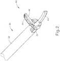
- FIG. 1illustrates an exemplary ultrasonic surgical instrument (10) that is configured to be used in minimally invasive surgical procedures (e.g., via a trocar or other small diameter access port, etc.).
- Instrument (10) of this examplecomprises a handle assembly (20), a shaft assembly (30), and an end effector (40).
- shaft assembly (30)comprises an outer sheath (32), an inner tube (34) slidably disposed within outer sheath (32), and a waveguide (38) disposed within inner tube (34).
- longitudinal translation of inner tube (34) relative to outer sheath (32)causes actuation of clamp arm (44) at end effector (40).
- Handle assembly (20)comprises a body (22) including a pistol grip (24) and a pair of buttons (26). Handle assembly (20) also includes a trigger (28) that is pivotable toward and away from pistol grip (24). It should be understood, however, that various other suitable configurations may be used, including but not limited to a scissor grip configuration. In the present example, a resilient member biases trigger (28) away from pistol grip (24). Trigger (28) is pivotable toward pistol grip (24) to drive inner tube (34) proximally relative to outer sheath (32). When trigger (28) is thereafter released or driven away from pistol grip (24), inner tube (34) is driven distally relative to outer sheath (32).
- trigger (28)may be coupled with inner tube (34) in accordance with the teachings of various references cited herein.
- Other suitable ways in which trigger (28) may be coupled with inner tube (34)will be apparent to those of ordinary skill in the art in view of the teachings herein.
- end effector (40)includes an ultrasonic blade (42) and a pivoting clamp arm (44).
- Clamp arm (44)includes a clamp pad (46) facing ultrasonic blade (42).
- Clamp arm (44)is pivotably coupled with a distal end of outer sheath (32) of shaft assembly (30), above ultrasonic blade (42), via a pin (33).
- a distal end of inner tube (34)is pivotably coupled with a proximal end of clamp arm (44), below ultrasonic blade (42), via another pin (35).
- longitudinal translation of inner tube (34) relative to outer sheath (32)causes clamp arm (44) to pivot about pin (33) toward and away from ultrasonic blade (42) to thereby clamp tissue between clamp pad (46) and ultrasonic blade (42) to transect and/or seal the tissue.
- proximal longitudinal translation of inner tube (34) relative to outer sheath (32) and handle assembly (20)causes clamp arm (44) to pivot toward ultrasonic blade (42); and distal longitudinal translation of inner tube (34) relative to outer sheath (32) and handle assembly (20) causes clamp arm (44) to pivot away from ultrasonic blade (42).
- An ultrasonic transducer assembly (12)extends proximally from body (22) of handle assembly (20). Transducer assembly (12) is coupled with a generator (16) via a cable (14). Transducer assembly (12) receives electrical power from generator (16) and converts that power into ultrasonic vibrations through piezoelectric principles.
- Generator (16)may include a power source and control module that is configured to provide a power profile to transducer assembly (12) that is particularly suited for the generation of ultrasonic vibrations through transducer assembly (12).
- generator (16)may comprise a GEN 300 sold by Ethicon Endo-Surgery, Inc. of Cincinnati, Ohio.
- generator (16)may be constructed in accordance with at least some of the teachings of U.S.
- generator (16)may be integrated into handle assembly (20), and that handle assembly (20) may even include a battery or other on-board power source such that cable (14) is omitted. Still other suitable forms that generator (16) may take, as well as various features and operabilities that generator (16) may provide, will be apparent to those of ordinary skill in the art in view of the teachings herein.
- Ultrasonic vibrations that are generated by transducer assembly (12)are communicated along an acoustic waveguide (38), which extends through shaft assembly (30) to reach ultrasonic blade (42).
- Waveguide (38)is secured within shaft assembly (30) via a pin (not shown), which passes through waveguide (38) and shaft assembly (30). This pin is located at a position along the length of waveguide (38) corresponding to a node associated with resonant ultrasonic vibrations communicated through waveguide (38).
- ultrasonic blade (42)when ultrasonic blade (42) is in an activated state (i.e., vibrating ultrasonically), ultrasonic blade (42) is operable to effectively cut through and seal tissue, particularly when the tissue is being clamped between clamp pad (46) and ultrasonic blade (42).
- waveguide (38)may be configured to amplify mechanical vibrations transmitted through waveguide (38). Furthermore, waveguide (38) may include features operable to control the gain of the longitudinal vibrations along waveguide (38) and/or features to tune waveguide (38) to the resonant frequency of the system.
- the distal end of ultrasonic blade (42)is located at a position corresponding to an anti-node associated with resonant ultrasonic vibrations communicated through waveguide (38), in order to tune the acoustic assembly to a preferred resonant frequency f ⁇ when the acoustic assembly is not loaded by tissue.
- the distal end of ultrasonic blade (42)is configured to move longitudinally in the range of, for example, approximately 10 to 500 microns peak-to-peak, and in some instances in the range of about 20 to about 200 microns at a predetermined vibratory frequency f ⁇ of, for example, 55.5 kHz.
- transducer assembly (12) of the present exampleWhen transducer assembly (12) of the present example is activated, these mechanical oscillations are transmitted through the waveguide to reach ultrasonic blade (102), thereby providing oscillation of ultrasonic blade (102) at the resonant ultrasonic frequency.
- ultrasonic blade (42)when tissue is secured between ultrasonic blade (42) and clamp pad (46), the ultrasonic oscillation of ultrasonic blade (42) may simultaneously sever the tissue and denature the proteins in adjacent tissue cells, thereby providing a coagulative effect with relatively little thermal spread.
- an electrical currentmay also be provided through ultrasonic blade (42) and/or clamp pad (46) to also seal the tissue.
- buttons (26)may be activate buttons (26) to selectively activate transducer assembly (12) to thereby activate ultrasonic blade (42).
- two buttons (26)are provided - one for activating ultrasonic blade (42) at a low power and another for activating ultrasonic blade (42) at a high power.
- a foot pedalmay be provided to selectively activate transducer assembly (12).
- Buttons (26) of the present exampleare positioned such that an operator may readily fully operate instrument (10) with a single hand. For instance, the operator may position their thumb about pistol grip (24), position their middle, ring, and/or little finger about trigger (28), and manipulate buttons (26) using their index finger.
- any other suitable techniquesmay be used to grip and operate instrument (10); and buttons (26) may be located at any other suitable positions.
- instrument (10)may be configured in numerous other ways as will be apparent to those of ordinary skill in the art in view of the teachings herein.
- at least part of instrument (10)may be constructed and/or operable in accordance with at least some of the teachings of any of the following: U.S. Pat. No. 5,322,055 ; U.S. Pat. No. 5,873,873 ; U.S. Pat. No. 5,980,510 ; U.S. Pat. No. 6,325,811 ; U.S. Pat. No. 6,783,524 ; U.S. Pub. No. 2006/0079874 ; U.S. Pub. No.
- FIG. 4illustrates an exemplary ultrasonic surgical instrument (100) that is configured to be used in open surgical procedures.
- Instrument (100) of this examplecomprises a handle assembly (120), a shaft assembly (130), and an end effector (140).
- Handle assembly (120)comprises a body (122) including a finger grip ring (124) and a pair of buttons (126).
- Instrument (100)also includes a clamp arm assembly (150) that is pivotable toward and away from body (122).
- Clamp arm (150)includes a shank (152) with a thumb grip ring (154).
- Thumb grip ring (154) and finger grip ring (124)together provide a scissor grip type of configuration. It should be understood, however, that various other suitable configurations may be used, including but not limited to a pistol grip configuration.
- Shaft assembly (130)comprises an outer sheath (132) extending distally from body (122).
- a cap (134)is secured to the distal end of sheath (132).
- end effector (140)comprises an ultrasonic blade (142) and a clamp arm (144).
- Ultrasonic blade (142)extends distally from cap (134).
- Clamp arm (144)is an integral feature of clamp arm assembly (150).
- Clamp arm (144)includes a clamp pad (146) facing ultrasonic blade (142).
- Clamp arm assembly (150)is pivotally coupled with outer sheath (132) via a pin (156).
- Clamp arm (144)is positioned distal to pin (156); while shank (152) and thumb grip ring (154) are positioned proximal to pin (156).
- clamp arm (144)is pivotable toward and away from ultrasonic blade (142) based on pivoting of thumb grip ring (154) toward and away from body (122) of handle assembly (120). It should therefore be understood that an operator may squeeze thumb grip ring (154) toward body (122) to thereby clamp tissue between clamp pad (146) and ultrasonic blade (142) to transect and/or seal the tissue.
- one or more resilient membersare used to bias clamp arm (144) to the open position shown in FIG. 6A .
- such a resilient membermay comprise a leaf spring, a torsion spring, and/or any other suitable kind of resilient member.
- an ultrasonic transducer assembly (112)extends proximally from body (122) of handle assembly (120). Transducer assembly (112) is coupled with a generator (116) via a cable (114). Transducer assembly (112) receives electrical power from generator (116) and converts that power into ultrasonic vibrations through piezoelectric principles.
- Generator (116)may include a power source and control module that is configured to provide a power profile to transducer assembly (112) that is particularly suited for the generation of ultrasonic vibrations through transducer assembly (112).
- generator (116)may comprise a GEN 300 sold by Ethicon Endo-Surgery, Inc. of Cincinnati, Ohio.
- generator (116)may be constructed in accordance with at least some of the teachings of U.S. Pub. No. 2011/0087212 , entitled “Surgical Generator for Ultrasonic and Electrosurgical Devices,” published April 14, 2011. It should also be understood that at least some of the functionality of generator (116) may be integrated into handle assembly (120), and that handle assembly (120) may even include a battery or other on-board power source such that cable (114) is omitted. Still other suitable forms that generator (116) may take, as well as various features and operabilities that generator (116) may provide, will be apparent to those of ordinary skill in the art in view of the teachings herein.
- Ultrasonic vibrations that are generated by transducer assembly (112)are communicated along an acoustic waveguide (138), which extends through shaft assembly (130) to reach ultrasonic blade (142).
- Waveguide (138)is secured within shaft assembly (130) via a pin (not shown), which passes through waveguide (138) and shaft assembly (130). This pin is located at a position along the length of waveguide (138) corresponding to a node associated with resonant ultrasonic vibrations communicated through waveguide (138).
- ultrasonic blade (142)when ultrasonic blade (142) is in an activated state (i.e., vibrating ultrasonically), ultrasonic blade (142) is operable to effectively cut through and seal tissue, particularly when the tissue is being clamped between clamp pad (146) and ultrasonic blade (142).
- waveguide (138)may be configured to amplify mechanical vibrations transmitted through waveguide (138).
- waveguide (138)may include features operable to control the gain of the longitudinal vibrations along waveguide (138) and/or features to tune waveguide (138) to the resonant frequency of the system.
- the distal end of ultrasonic blade (142)is located at a position corresponding to an anti-node associated with resonant ultrasonic vibrations communicated through waveguide (138), in order to tune the acoustic assembly to a preferred resonant frequency f o when the acoustic assembly is not loaded by tissue.
- the distal end of ultrasonic blade (142)is configured to move longitudinally in the range of for example, approximately 10 to 500 microns peak-to-peak, and in some instances in the range of about 20 to about 200 microns at a predetermined vibratory frequency f ⁇ of, for example, 55.5 kHz.
- transducer assembly (112) of the present exampleWhen transducer assembly (112) of the present example is activated, these mechanical oscillations are transmitted through the waveguide to reach ultrasonic blade (102), thereby providing oscillation of ultrasonic blade (102) at the resonant ultrasonic frequency.
- the ultrasonic oscillation of ultrasonic blade (142)may simultaneously sever the tissue and denature the proteins in adjacent tissue cells, thereby providing a coagulative effect with relatively little thermal spread.
- an electrical currentmay also be provided through ultrasonic blade (142) and/or clamp pad (146) to also seal the tissue.
- buttons (126)may activate buttons (126) to selectively activate transducer assembly (112) to thereby activate ultrasonic blade (142).
- two buttons (126)are provided - one for activating ultrasonic blade (142) at a low power and another for activating ultrasonic blade (142) at a high power.
- a foot pedalmay be provided to selectively activate transducer assembly (112).
- Buttons (126) of the present exampleare positioned such that an operator may readily fully operate instrument (100) with a single hand.
- buttons (126)may be located at any other suitable positions.
- instrument (100)may be configured in numerous other ways as will be apparent to those of ordinary skill in the art in view of the teachings herein.
- at least part of instrument (100)may be constructed and/or operable in accordance with at least some of the teachings of any of the following: U.S. Pat. No. 5,322,055 ; U.S. Pat. No. 5,873,873 ; U.S. Pat. No. 5,980,510 ; U.S. Pat. No. 6,325,811 ; U.S. Pat. No. 6,783,524 ; U.S. Pub. No. 2006/0079874 ; U.S. Pub.
- one or more regions of instrument (10, 100)may heat up during extended operation of instrument (10, 100) in a surgical procedure.
- blade (42, 142), clamp arm (44, 144), and/or other portions of instrument (10, 100)may eventually heat up over time. Such heating may be caused by friction and/or other factors.
- the heatmay be initially generated in one particular component of instrument (10, 100) (e.g., blade (42, 142) or clamp arm (44, 144), etc.), such heat may be gradually transmitted to other portions of instrument (10, 100). It may be desirable to minimize such heating and/or otherwise manage such heating in order to avoid having heated portions of instrument (10, 100) contact tissue that should not be heated.
- end effector (40, 140)may wish for end effector (40, 140) to be relatively cool when the operator wishes to use end effector (40, 140) to perform spreading blunt dissections and/or simple tissue grasping, etc. It may also be desirable to minimize heat and/or otherwise manage heat in a way that does not significantly increase the size or operability of instrument (10, 100). Several examples of how heating may be minimized and/or otherwise managed are described in greater detail below; while other examples will be apparent to those of ordinary skill in the art in view of the teachings herein.
- one or more portions of instrument (10, 100)may include a thermal insulator or barrier coating (e.g., a thin coating of thermal insulator or barrier material with a very low thermal conductivity).
- a thermal insulator or barrier coatingis a nanocomposite (e.g., hydro-NM-oxide) in an acrylic resin suspension.
- An example of such a coatingis NANSULATE® coating by Industrial Nanotech, Inc. of Naples, Florida.
- Additional merely illustrative examples of thermal insulator or barrier coatingsinclude the following: EST 1711 by Ellison Surface Technologies, Inc. of Mason, Ohio; EST 1732 by Ellison Surface Technologies, Inc.
- a thermal insulator or barrier coatingmay be applied to various external surfaces of instrument (10, 100), such as regions of blade (42, 142) that are not intended to contact tissue, clamp arm (44, 144), clamp pad (46, 146), outer sheath (32, 132), cap (134), etc.
- a coatingmay be applied to various internal surfaces of instrument (10, 100), such as surfaces in generator (16, 116), transducer assembly (12, 112), internal electronics components, etc.
- such a coatingmay serve as a corrosion barrier, fire block, etc.
- the coatingmay also be applied to one or more regions of such components.
- Other suitable ways in which a thermal coating may be incorporated into instrument (10, 100) and variations thereofwill be apparent to those of ordinary skill in the art in view of the teachings herein.
- One merely exemplary way in which heat may be managed in instrument (10, 100)is to use a fluid to cool blade (42, 142).
- a cooling liquide.g., saline, etc.
- the cooling fluidmay then be communicated distally along the rest of the length of blade (42, 142) to thereby cool blade.
- the ultrasonic vibration of blade (42, 142)may provide such distal communication of the fluid.
- a particular vibrational schememay be used to drive liquid distally along blade (42, 142). Such a particular, vibrational scheme may have no meaningful effect on tissue that is in contact with blade (42, 142) while blade is being driven in such a fashion.
- blade (42, 142)may be vibrated in short pulses (e.g., of approximately 10 to 20 millisecond duration) of low amplitude motion to drive the liquid distally along blade (42, 142).
- generator (16, 116)is programmed to provide such liquid driving ultrasonic activation of blade (42, 142) when the operator is not pressing any buttons (26, 126).
- generator (16, 116)may be programmed to provide liquid driving ultrasonic activation of blade (42, 142) when generator (16, 116) detects that blade (42, 142) is not contacting tissue.
- instrument (10, 100)may include a separate user input feature that is operable to manually trigger a liquid driving vibrational scheme. Other suitable ways in which a liquid driving vibrational scheme may be triggered will be apparent to those of ordinary skill in the art in view of the teachings herein.
- the same vibrational movement that is used to drive blade during tissue cutting/sealingmay drive liquid distally along blade (42, 142).
- fluidmay be communicated to and/or along blade in accordance with at least some of the teachings of U.S. Pub. No. 2011/0152759 , entitled “Use of Biomarkers and Therapeutic Agents with Surgical Devices," published June 23, 2011. It should be understood that the teachings in U.S. Pub. No. 2011/0152759 relating to dispensation of medical fluids may be readily adapted to provide communication of cooling fluid.
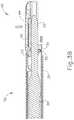
- FIGS. 7A-7Bshow an exemplary alternative end effector (240) positioned at the distal end of an exemplary alternative shaft assembly (230).
- End effector (240) of this exampleis substantially identical to end effector (40) described above.
- end effector (240)includes an ultrasonic blade (242) and a pivoting clamp arm (244) with clamp pad (246).
- Shaft assembly (230)is substantially similar to shaft assembly (30) described above.
- shaft assembly (230)includes an outer sheath (232) and an inner tube (234). Outer sheath (232) is pivotably coupled with clamp arm (244) via a pin (233); while inner tube (234) is pivotably coupled with clamp arm (244) via a pin (235).
- Inner tube (234)translates relative to outer sheath (232) to selectively pivot clamp arm (244) toward ( FIG. 7A ) and away from ( FIG. 7B ) blade (242).
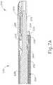
- inner tube (234) of this exampleincludes an inwardly directed protrusion (260).
- Protrusion (260)is configured to engage a cooling feature (250).
- Cooling feature (250)is disposed between waveguide (238) and inner tube (234). Cooling feature (250) includes a cantilever beam (252), which is mechanically grounded relative to outer sheath (232). Inner tube (234) thus translates relative to cantilever beam (252) when inner tube (234) translates relative to outer sheath (232).
- a hydrophilic pad (254)is located at the distal end of cantilever beam (252).
- pad (254)may comprise a foam material.
- suitable material(s) that may be used to form pad (254)will be apparent to those of ordinary skill in the art in view of the teachings herein. As seen in the transition from FIG. 7A to FIG.
- protrusion (260) of inner tube (34)is configured to drive pad (254) into engagement with the proximal end of blade (242) each time inner tube (234) translates distally relative to cantilever beam (252) and outer sheath (232). This occurs due to a camming engagement by protrusion (260) against the underside of cantilever beam (252).
- Cantilever beam (252)is bent such that protrusion (260) disengages the underside of cantilever beam (252) when inner tube (234) returns to a proximal position relative to cantilever beam (252) and outer sheath (232).
- Cantilever beam (252)is resiliently biased to disengage pad (254) from the proximal end of blade (242) when protrusion (260) is disengaged from the underside of cantilever beam (252).
- pad (254)is saturated in a cooling fluid, such that pad (254) applies the cooling fluid to blade (242) when pad (254) engages blade (242).
- the saturated pad (254)may thereby quench or otherwise cool blade (242) each time clamp arm (244) is pivoted away from blade (242).
- the operatormay dip end effector (240) and the distal end of shaft assembly (230) into a container holding saline or some other cooling fluid in order to saturate or otherwise wet pad (254). This may be done at the beginning of a surgical procedure and/or during a surgical procedure.
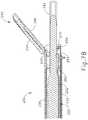
- FIG. 8shows an exemplary alternative cooling feature (250) that comprises a cantilever beam (272), a hydrophilic pad (274), and a wicking feature (276) extending proximally from hydrophilic pad (274) along an upper side of cantilever beam (272).
- Wicking feature (276)is in fluid communication with pad (274) such that fluid absorbed by pad (274) may be wicked into wicking feature (276) by a capillary action.
- pad (274)starts to dry out (e.g., after engaging a warm blade (242) one or more times, etc.)
- fluid in wicking feature (276)may be drawn back into pad (274) through a capillary action.
- a fluid conduitmay be coupled with wicking feature (276) and/or pad (254, 274) to communicate fluid directly to wicking feature (276) and/or pad (254, 274) from a source external to the patient (e.g., a reservoir within a handle assembly, etc.).
- wicking feature (276) and/or pad (254, 274)may be replenished with fluid during a surgical procedure without having to remove end effector (240) from the patient.
- steammay be generated at the surgical site when blade (242) cuts and seals tissue.
- Wicking feature (276) and/or pad (254, 274)may absorb fluid from such steam during the surgical procedure. The same concept may also apply to any other absorbent pad described herein.
- cantilever beams (252, 272) and pads (254, 274)are shown as being generally flat in the present example, it should be understood that cantilever beams (252, 272) and pads (254, 274) may instead have a curved profile to complement the curvature of waveguide (238), blade (242), and inner tube (234). As another merely illustrative variation, pad (254, 274) may contact waveguide (238) instead of contacting blade (242). Still other suitable variations will be apparent to those of ordinary skill in the art in view of the teachings herein.
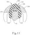
- FIGS. 9-11show an exemplary alternative clamp arm (300) that may be used as a substitute for clamp arm (44).
- Clamp arm (300) of this exampleincludes a longitudinally extending support beam (306), a clamp pad (310), and a cooling pad (320).
- Clamp pad (310)is secured to the underside of support beam (306).
- Cooling pad (320)is insertable through two channels (302, 304) formed in clamp arm (300) on opposite sides of support beam (306).
- cooling pad (320)may be bent to form an upside-down "U" shape; and may then be draped over a support beam (306) defined by clamp arm (300). Cooling pad (320) may remain in place due to friction.
- pad (320)may comprise a foam material.
- suitable material(s) that may be used to form pad (320)will be apparent to those of ordinary skill in the art in view of the teachings herein.
- free ends (322, 324)drape over the sides of blade (42) when clamp arm (300) is in a closed position relative to blade (42).
- Free ends (322, 324)define a gap distance that is less the width of blade (42), such that free ends (322, 324) bear inwardly against the outer surfaces of blade (42) when clamp arm (300) is in a closed position relative to blade (42) as shown in FIG. 11 .
- tissuemay initially be captured between clamp arm (300) and blade (42) such that the tissue is interposed between pad (320) and blade (42).
- Clamp pad (310) and blade (42)may cooperate to sever and seal the tissue, which may then separate from blade (42).
- pad (320)may directly engage blade (42) as shown in FIG. 11 . It should therefore be understood that pad (320) may engage blade (42) as shown in FIG. 11 right after blade (42) has severed and sealed tissue captured between clamp pad (310) and blade (42).
- Pad (320) of this examplemay be used similar to pad (254, 274) described above.
- pad (320)may be saturated or otherwise wetted with a cooling fluid (e.g., saline, etc.).
- Pad (320)may thus apply the cooling fluid to blade (42) when pad (320) engages blade (42), such that the saturated pad (320) quenches or otherwise cools blade (42) each time clamp arm (300) reaches a closed position relative to blade (42).
- An end effector that is fitted with clamp arm (300)may be dipped into a container holding saline or some other cooling fluid in order to saturate or otherwise wet pad (320). This may be done at the beginning of a surgical procedure and/or during a surgical procedure.
- pad (320)may absorb fluid from vapor emitted by tissue during a surgical procedure and/or other fluid from a surgical site.
- a fluid conduitmay be coupled with pad (320) to communicate fluid directly to pad (320) from a source external to the patient (e.g., a reservoir within a handle assembly, etc.).
- a source external to the patiente.g., a reservoir within a handle assembly, etc.
- pad (320)may be saturated or otherwise wetted will be apparent to those of ordinary skill in the art in view of the teachings herein.
- FIGS. 12-13show another exemplary clamp arm (350) that may be combined with pad (320).
- Clamp arm (350) of this examplemay also be used as a substitute for clamp arm (44).
- Clamp arm (350) of this exampleincludes a pair of engagement channels (352, 354) that are longitudinally spaced apart from each other. Each engagement channel (352, 354) includes a respective internal shelf (356, 358).
- a retaining member (360)is configured to engage clamp arm (350).
- a clamp pad (370)is secured to the underside of retaining member (360).
- Retaining member (360)includes a pair of transversely extending arms (362, 364). Each arm (362, 364) includes a respective latch (366, 368). Arms (362, 364) are configured to be inserted through corresponding engagement channels (352, 354), such that latches (366, 368) engage corresponding shelves (356, 358) to secure retaining member (360) to clamp arm (350) in a snap fit.
- Retaining member (360)is configured to secure pad (320) relative to clamp arm (350).
- pad (320)may be draped over retaining member (360); and retaining member (360) may then be secured to clamp arm (350) as described above such that pad (320) is captured between retaining member (360) and clamp arm (350).
- Free ends (322, 324)may again extend below clamp arm (300) and below clamp pad (310), such that pad (320) may engage a blade (42), in a manner similar to that shown in FIG. 11 and described above, when clamp arm (350) is in a closed position relative to blade (42).
- pad (320)when pad (320) is saturated or otherwise wetted with a cooling fluid, pad (320) may quench or otherwise cool blade (42) when clamp arm (350) is in a closed position relative to blade (42).
- a clamp armmay incorporate a cooling pad will be apparent to those of ordinary skill in the art in view of the teachings herein.
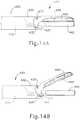
- FIGS. 14A-15show an exemplary alternative end effector (440) positioned at the distal end of an exemplary alternative shaft assembly (430).
- End effector (440) of this exampleis substantially similar to end effector (40) described above.
- end effector (440)includes an ultrasonic blade (442) and a pivoting clamp arm (444) with clamp pad (446).
- Shaft assembly (430)is substantially similar to shaft assembly (30) described above.
- shaft assembly (430)includes an outer sheath (432) and an inner tube (434). Outer sheath (432) is pivotably coupled with clamp arm (444) via a pin (433); while inner tube (434) is pivotably coupled with clamp arm (444) via a pin (435).
- Inner tube (434)translates relative to outer sheath (432) to selectively pivot clamp arm (444) toward ( FIG. 14A ) and away from ( FIG. 14B ) blade (442).
- the distal end (437) of inner tube (434) of this exampleis resilient and includes an integral cooling pad (450).
- outer sheath (432) of this exampleincludes a camming feature (452).
- the distal end (437) of inner tube (434)is bent to form a "U" shape; and pad (450) also defines a "U” shape. This shape complements the configuration of blade (442).
- the distal end (437) of inner tube (434) and camming feature (452) of outer sheath (432)are configured such that camming feature (452) drives the distal end of inner tube (434) inwardly toward blade (442) when inner tube (434) travels distally, as shown in FIG. 14B .
- the resilience of the distal end of inner tube (434)drives the distal end (437) of inner tube (434) outwardly.
- distal end (437)comprises a plastic material that is insert molded with a metal material that forms the remainder of inner tube (434). In some other versions, distal end (437) is unitarily formed by a metal material that forms the remainder of inner tube (434). Other suitable ways in which distal end (437) may be formed will be apparent to those of ordinary skill in the art in view of the teachings herein. Also by way of example only, pad (450) may comprise a foam material. Various suitable material(s) that may be used to form pad (450) will be apparent to those of ordinary skill in the art in view of the teachings herein.
- pad (450)may be saturated or otherwise wetted with a cooling fluid (e.g., saline, etc.).
- a cooling fluide.g., saline, etc.
- Pad (450)may thus apply the cooling fluid to blade (442) when pad (450) engages blade (442), such that the saturated pad (450) quenches or otherwise cools blade (442) each time end effector (440) reaches an open configuration.
- End effector (440)may be dipped into a container holding saline or some other cooling fluid in order to saturate or otherwise wet pad (450). This may be done at the beginning of a surgical procedure and/or during a surgical procedure.
- pad (450)may absorb fluid from vapor emitted by tissue during a surgical procedure and/or other fluid from a surgical site.
- a fluid conduitmay be coupled with pad (450) to communicate fluid directly to pad (450) from a source external to the patient (e.g., a reservoir within a handle assembly, etc.).
- a source external to the patiente.g., a reservoir within a handle assembly, etc.
- pad (450)may be saturated or otherwise wetted will be apparent to those of ordinary skill in the art in view of the teachings herein.
- one or more shielding featuresmay be used to avoid direct contact between a hot portion of instrument (10, 100) and tissue (or other structures).
- a gapmay be defined between the shielding feature and the corresponding hot portion of instrument (10, 100), to avoid or minimize communication of heat from the hot portion of instrument (10, 100) and the shielding feature.
- Such a gapmay be filled with liquid, air or some other gas, a solid insulating material, and/or any other suitable kind of filler, including combinations thereof.
- a shielding feature(and/or a hot feature of instrument (10, 100)) may include external surface structures such as a roughened surface, grooves, dimples, pimples, nubs, knurling, a honeycomb structure, etc., to minimize transfer of heat from the shielding feature (or hot feature) to adjacent tissue, etc.
- the heating at an end effector (40, 140)may be caused or hastened by direct contact between clamp pad (46, 146) and blade (42, 142) while clamp arm (44, 144) is closed and blade (42, 142) is activated, etc.
- Such direct contactmay occur at regions where tissue is not interposed between clamp pad (46, 146) and blade (42, 142).
- Some operatorsmay position tissue just between the distal portion of clamp pad (46, 146) and the distal portion of blade (42, 142). This may occur when end effector (40, 140) is used to transect relatively small vessels.
- clamp pad (46, 146) and blade (42, 142)may both contact the tissue compressed between clamp pad (46, 146) and blade (42, 142); yet the proximal portions of clamp pad (46, 146) and blade (42, 142) may just directly contact each other.
- blade (42, 142)is activated in such instances, clamp pad (46, 146) and blade (42, 142) may rapidly generate a significant amount of heat at the proximal portions where the direct contact occurs.
- Versions of the devices described abovemay have application in conventional medical treatments and procedures conducted by a medical professional, as well as application in robotic-assisted medical treatments and procedures.
- various teachings hereinmay be readily incorporated into a robotic surgical system such as the DAVINCITM system by Intuitive Surgical, Inc., of Sunnyvale, California.
- DAVINCITM systemby Intuitive Surgical, Inc., of Sunnyvale, California.
- teachings hereinmay be readily combined with various teachings of U.S. Pat. No. 6,783,524 , entitled “Robotic Surgical Tool with Ultrasound Cauterizing and Cutting Instrument,” published August 31, 2004.
- Versions described abovemay be designed to be disposed of after a single use, or they can be designed to be used multiple times. Versions may, in either or both cases, be reconditioned for reuse after at least one use. Reconditioning may include any combination of the steps of disassembly of the device, followed by cleaning or replacement of particular pieces, and subsequent reassembly. In particular, some versions of the device may be disassembled, and any number of the particular pieces or parts of the device may be selectively replaced or removed in any combination. Upon cleaning and/or replacement of particular parts, some versions of the device may be reassembled for subsequent use either at a reconditioning facility, or by a user immediately prior to a procedure.
- reconditioning of a devicemay utilize a variety of techniques for disassembly, cleaning/replacement, and reassembly. Use of such techniques, and the resulting reconditioned device, are all within the scope of the present application.
- versions described hereinmay be sterilized before and/or after a procedure.
- the deviceis placed in a closed and sealed container, such as a plastic or TYVEK bag.
- the container and devicemay then be placed in a field of radiation that can penetrate the container, such as gamma radiation, x-rays, or high-energy electrons.
- the radiationmay kill bacteria on the device and in the container.
- the sterilized devicemay then be stored in the sterile container for later use.
- a devicemay also be sterilized using any other technique known in the art, including but not limited to beta or gamma radiation, ethylene oxide, or steam.
Landscapes
- Health & Medical Sciences (AREA)
- Life Sciences & Earth Sciences (AREA)
- Surgery (AREA)
- Engineering & Computer Science (AREA)
- General Health & Medical Sciences (AREA)
- Veterinary Medicine (AREA)
- Nuclear Medicine, Radiotherapy & Molecular Imaging (AREA)
- Biomedical Technology (AREA)
- Public Health (AREA)
- Animal Behavior & Ethology (AREA)
- Molecular Biology (AREA)
- Medical Informatics (AREA)
- Heart & Thoracic Surgery (AREA)
- Dentistry (AREA)
- Mechanical Engineering (AREA)
- Radiology & Medical Imaging (AREA)
- Ophthalmology & Optometry (AREA)
- Surgical Instruments (AREA)
Description
- This application claims priority to
U.S. Provisional Patent App. No. 61/908,920 - A variety of surgical instruments include an end effector having a blade element that vibrates at ultrasonic frequencies to cut and/or seal tissue (e.g., by denaturing proteins in tissue cells). These instruments include piezoelectric elements that convert electrical power into ultrasonic vibrations, which are communicated along an acoustic waveguide to the blade element. The precision of cutting and coagulation may be controlled by the surgeon's technique and adjusting the power level, blade edge, tissue traction and blade pressure.
- Examples of ultrasonic surgical instruments include the HARMONIC ACE® Ultrasonic Shears, the HARMONIC WAVE® Ultrasonic Shears, the HARMONIC FOCUS® Ultrasonic Shears, and the HARMONIC SYNERGY® Ultrasonic Blades, all by Ethicon Endo-Surgery, Inc. of Cincinnati, Ohio. Further examples of such devices and related concepts are disclosed in
U.S. Pat. No. 5,322,055 , entitled "Clamp Coagulator/Cutting System for Ultrasonic Surgical Instruments," issued June 21, 1994;U.S. Pat. No. 5,873,873 , entitled "Ultrasonic Clamp Coagulator Apparatus Having Improved Clamp Mechanism," issued February 23, 1999;U.S. Pat. No. 5,980,510 , entitled "Ultrasonic Clamp Coagulator Apparatus Having Improved Clamp Arm Pivot Mount," filed October 10, 1997;U.S. Pat. No. 6,325,811 , entitled "Blades with Functional Balance Asymmetries for use with Ultrasonic Surgical Instruments," issued December 4, 2001;U.S. Pat. No. 6,773,444 , entitled "Blades with Functional Balance Asymmetries for Use with Ultrasonic Surgical Instruments," issued August 10, 2004; andU.S. Pat. No. 6,783,524 , entitled "Robotic Surgical Tool with Ultrasound Cauterizing and Cutting Instrument," issued August 31, 2004. - Still further examples of ultrasonic surgical instruments are disclosed in
U.S. Pub. No. 2006/0079874 , entitled "Tissue Pad for Use with an Ultrasonic Surgical Instrument," published April 13, 2006;U.S. Pub. No. 2007/0191713 , entitled "Ultrasonic Device for Cutting and Coagulating," published August 16, 2007;U.S. Pub. No. 2007/0282333 , entitled "Ultrasonic Waveguide and Blade," published December 6, 2007;U.S. Pub. No. 2008/0200940 , entitled "Ultrasonic Device for Cutting and Coagulating," published August 21, 2008;U.S. Pub. No. 2009/0105750 , entitled "Ergonomic Surgical Instruments," published April 23, 2009;U.S. Pub. No. 2010/0069940 , entitled "Ultrasonic Device for Fingertip Control," published March 18, 2010; andU.S. Pub. No. 2011/0015660 , entitled "Rotating Transducer Mount for Ultrasonic Surgical Instruments," published January 20, 2011; andU.S. Pub. No. 2012/0029546 , entitled "Ultrasonic Surgical Instrument Blades," published February 2, 2012. - Some of ultrasonic surgical instruments may include a cordless transducer such as that disclosed in
U.S. Pub. No. 2012/0112687 , entitled "Recharge System for Medical Devices," published May 10, 2012;U.S. Pub. No. 2012/0116265 , entitled "Surgical Instrument with Charging Devices," published May 10, 2012; and/orU.S. Pat. App. No. 61/410,603, filed November 5, 2010 - Additionally, some ultrasonic surgical instruments may include an articulating shaft section. Examples of such ultrasonic surgical instruments are disclosed in
U.S. Pub. No. 2014/0005701 , entitled "Surgical Instruments with Articulating Shafts," published January 2, 2014; andU.S. Pub. No. 2014/0114334 , entitled "Flexible Harmonic Waveguides/Blades for Surgical Instruments," published April 24, 2014. US 2011/152759 A1 describes use of biomarkers and therapeutic agents with surgical devices. Biomarkers are collected and used to determine biological propensities of a patient, to determine the efficacy of medical devices, to select and administer therapeutic agents, to select medical devices, to make adjustments to medical devices, and/or to adjust surgical techniques. A described apparatus includes a port to draw a biological fluid (e.g., a mist) from a surgical site. The apparatus includes a sensor having a cantilevered beam. The beam includes substances selected to attract certain biomarkers as the fluid is communicated across the beam. The same apparatus or another apparatus is used to administer a therapeutic agent based at least in part on collected biomarker data. The therapeutic agent delivery apparatus may include a device that is also used to create a wound at a surgical site. For instance, a harmonic surgical instrument may be used to both collect biomarkers and administer a therapeutic agent (e.g., gene therapy using sonoporation).- While several surgical instruments and systems have been made and used, it is believed that no one prior to the inventors has made or used the invention described in the appended claims.
- The invention is defined by the appended claims.
- While the specification concludes with claims which particularly point out and distinctly claim this technology, it is believed this technology will be better understood from the following description of certain examples taken in conjunction with the accompanying drawings, in which like reference numerals identify the same elements and in which:
FIG. 1 depicts a side elevational view of an exemplary surgical instrument;FIG. 2 depicts a perspective view of the end effector of the instrument ofFIG. 1 , in an open configuration;FIG. 3A depicts a side cross-sectional view of the end effector ofFIG. 2 , in the open configuration;FIG. 3B depicts a side cross-sectional view of the end effector ofFIG. 2 , in a closed configuration;FIG. 4 depicts a perspective view of another exemplary surgical instrument;FIG. 5 depicts a side elevational view of the end effector of the instrument ofFIG. 4 , in a closed configuration;FIG. 6A depicts a perspective view of the end effector ofFIG. 5 , in an open configuration;FIG. 6B depicts a perspective view of the end effector ofFIG. 5 , in a closed configuration;FIG. 7A depicts a cross-sectional side view of an exemplary alternative end effector of the invention, in a closed configuration, with a cooling element spaced away from the waveguide;FIG. 7B depicts a cross-sectional side view of the end effector ofFIG. 7A , in an open configuration, with the cooling element in contact with the waveguide;FIG. 8 depicts a perspective view of the cooling element ofFIG. 7A ;FIG. 9 depicts a perspective view of an exemplary alternative clamp arm of the invention;FIG. 10 depicts an exploded view of the clamp arm ofFIG. 9 ;FIG. 11 depicts a cross-sectional end view of the clamp arm ofFIG. 9 , clamped against an ultrasonic blade;FIG. 12 depicts a perspective view of another exemplary alternative clamp arm of the invention;FIG. 13 depicts an exploded view of the clamp arm ofFIG. 12 ;FIG. 14A depicts a side elevational view of another exemplary alternative end effector of the invention, in a closed configuration, with a cooling element spaced away from the ultrasonic blade;FIG. 14B depicts a side elevational view of the end effector ofFIG. 14A , in an open configuration, with the cooling element in contact with the ultrasonic blade; andFIG. 15 depicts a cross-sectional end view of the cooling element ofFIG. 14A in contact with the ultrasonic blade.- The drawings are not intended to be limiting in any way, and it is contemplated that various embodiments of the technology may be carried out in a variety of other ways, including those not necessarily depicted in the drawings. The accompanying drawings incorporated in and forming a part of the specification illustrate several aspects of the present technology, and together with the description serve to explain the principles of the technology; it being understood, however, that this technology is not limited to the precise arrangements shown.
- The following description of certain examples of the technology should not be used to limit its scope. Other examples, features, aspects, embodiments, and advantages of the technology will become apparent to those skilled in the art from the following description, which is by way of illustration, one of the best modes contemplated for carrying out the technology. As will be realized, the technology described herein is capable of other different and obvious aspects, all without departing from the technology. Accordingly, the drawings and descriptions should be regarded as illustrative in nature and not restrictive.
- It is further understood that any one or more of the teachings, expressions, embodiments, examples, etc. described herein may be combined with any one or more of the other teachings, expressions, embodiments, examples, etc. that are described herein. The following-described teachings, expressions, embodiments, examples, etc. should therefore not be viewed in isolation relative to each other. Various suitable ways in which the teachings herein may be combined will be readily apparent to those of ordinary skill in the art in view of the teachings herein. The invention is defined solely by the claims.
- For clarity of disclosure, the terms "proximal" and "distal" are defined herein relative to a human or robotic operator of the surgical instrument. The term "proximal" refers the position of an element closer to the human or robotic operator of the surgical instrument and further away from the surgical end effector of the surgical instrument. The term "distal" refers to the position of an element closer to the surgical end effector of the surgical instrument and further away from the human or robotic operator of the surgical instrument.
FIGS. 1-6B illustrate exemplary ultrasonic surgical instruments (10, 100). At least part of each instrument (10, 100) may be constructed and operable in accordance with at least some of the teachings ofU.S. Pat. No. 5,322,055 ;U.S. Pat. No. 5,873,873 ;U.S. Pat. No. 5,980,510 ;U.S. Pat. No. 6,325,811 ;U.S. Pat. No. 6,773,444 ;U.S. Pat. No. 6,783,524 ;U.S. Pub. No. 2006/0079874 ;U.S. Pub. No. 2007/0191713 ;U.S. Pub. No. 2007/0282333 ;U.S. Pub. No. 2008/0200940 ;U.S. Pub. No. 2009/0105750 ;U.S. Pub. No. 2010/0069940 ;U.S. Pub. No. 2011/0015660 ;U.S. Pub. No. 2012/0112687 ;U.S. Pub. No. 2012/0116265 ;U.S. Pub. No. 2014/0005701 ;U.S. Pub. No. 2014/0114334 ;U.S. Pat. App. No. 61/410,603 U.S. Pat. App. No. 14/028,717 , published asUS 2015/0080924 . As described therein and as will be described in greater detail below, each instrument (10, 100) is operable to cut tissue and seal or weld tissue (e.g., a blood vessel, etc.) substantially simultaneously. It should also be understood that instruments (10, 100) may have various structural and functional similarities with the HARMONIC ACE® Ultrasonic Shears, the HARMONIC WAVE® Ultrasonic Shears, the HARMONIC FOCUS® Ultrasonic Shears, and/or the HARMONIC SYNERGY® Ultrasonic Blades. Furthermore, instruments (10, 100) may have various structural and functional similarities with the devices taught in any of the other references that are cited.- To the extent that there is some degree of overlap between the teachings of the references cited herein, the HARMONIC ACE® Ultrasonic Shears, the HARMONIC WAVE® Ultrasonic Shears, the HARMONIC FOCUS® Ultrasonic Shears, and/or the HARMONIC SYNERGY® Ultrasonic Blades, and the following teachings relating to instruments (10, 100), there is no intent for any of the description herein to be presumed as admitted prior art. Several teachings herein will in fact go beyond the scope of the teachings of the references cited herein and the HARMONIC ACE® Ultrasonic Shears, the HARMONIC WAVES Ultrasonic Shears, the HARMONIC FOCUS® Ultrasonic Shears, and the HARMONIC SYNERGY® Ultrasonic Blades.
FIG. 1 illustrates an exemplary ultrasonic surgical instrument (10) that is configured to be used in minimally invasive surgical procedures (e.g., via a trocar or other small diameter access port, etc.). Instrument (10) of this example comprises a handle assembly (20), a shaft assembly (30), and an end effector (40). As shown inFIGS. 2-3B , shaft assembly (30) comprises an outer sheath (32), an inner tube (34) slidably disposed within outer sheath (32), and a waveguide (38) disposed within inner tube (34). As will be discussed in more detail below, longitudinal translation of inner tube (34) relative to outer sheath (32) causes actuation of clamp arm (44) at end effector (40). Handle assembly (20) comprises a body (22) including a pistol grip (24) and a pair of buttons (26). Handle assembly (20) also includes a trigger (28) that is pivotable toward and away from pistol grip (24). It should be understood, however, that various other suitable configurations may be used, including but not limited to a scissor grip configuration. In the present example, a resilient member biases trigger (28) away from pistol grip (24). Trigger (28) is pivotable toward pistol grip (24) to drive inner tube (34) proximally relative to outer sheath (32). When trigger (28) is thereafter released or driven away from pistol grip (24), inner tube (34) is driven distally relative to outer sheath (32). By way of example only, trigger (28) may be coupled with inner tube (34) in accordance with the teachings of various references cited herein. Other suitable ways in which trigger (28) may be coupled with inner tube (34) will be apparent to those of ordinary skill in the art in view of the teachings herein.- As shown in
FIGS. 2-3B , end effector (40) includes an ultrasonic blade (42) and a pivoting clamp arm (44). Clamp arm (44) includes a clamp pad (46) facing ultrasonic blade (42). Clamp arm (44) is pivotably coupled with a distal end of outer sheath (32) of shaft assembly (30), above ultrasonic blade (42), via a pin (33). A distal end of inner tube (34) is pivotably coupled with a proximal end of clamp arm (44), below ultrasonic blade (42), via another pin (35). Thus, longitudinal translation of inner tube (34) relative to outer sheath (32) causes clamp arm (44) to pivot about pin (33) toward and away from ultrasonic blade (42) to thereby clamp tissue between clamp pad (46) and ultrasonic blade (42) to transect and/or seal the tissue. In particular, as seen in the transition fromFIGS. 3A to FIG. 3B , proximal longitudinal translation of inner tube (34) relative to outer sheath (32) and handle assembly (20) causes clamp arm (44) to pivot toward ultrasonic blade (42); and distal longitudinal translation of inner tube (34) relative to outer sheath (32) and handle assembly (20) causes clamp arm (44) to pivot away from ultrasonic blade (42). It should therefore be understood that pivoting of trigger (28) toward pistol grip (24) will cause clamp arm (44) to pivot toward ultrasonic blade (42); and that pivoting of trigger (28) away from pistol grip (24) will cause clamp arm (44) to pivot away from ultrasonic blade (42). - An ultrasonic transducer assembly (12) extends proximally from body (22) of handle assembly (20). Transducer assembly (12) is coupled with a generator (16) via a cable (14). Transducer assembly (12) receives electrical power from generator (16) and converts that power into ultrasonic vibrations through piezoelectric principles. Generator (16) may include a power source and control module that is configured to provide a power profile to transducer assembly (12) that is particularly suited for the generation of ultrasonic vibrations through transducer assembly (12). By way of example only, generator (16) may comprise a
GEN 300 sold by Ethicon Endo-Surgery, Inc. of Cincinnati, Ohio. In addition or in the alternative, generator (16) may be constructed in accordance with at least some of the teachings ofU.S. Pub. No. 2011/0087212 , entitled "Surgical Generator for Ultrasonic and Electrosurgical Devices," published April 14, 2011. It should also be understood that at least some of the functionality of generator (16) may be integrated into handle assembly (20), and that handle assembly (20) may even include a battery or other on-board power source such that cable (14) is omitted. Still other suitable forms that generator (16) may take, as well as various features and operabilities that generator (16) may provide, will be apparent to those of ordinary skill in the art in view of the teachings herein. - Ultrasonic vibrations that are generated by transducer assembly (12) are communicated along an acoustic waveguide (38), which extends through shaft assembly (30) to reach ultrasonic blade (42). Waveguide (38) is secured within shaft assembly (30) via a pin (not shown), which passes through waveguide (38) and shaft assembly (30). This pin is located at a position along the length of waveguide (38) corresponding to a node associated with resonant ultrasonic vibrations communicated through waveguide (38). As noted above, when ultrasonic blade (42) is in an activated state (i.e., vibrating ultrasonically), ultrasonic blade (42) is operable to effectively cut through and seal tissue, particularly when the tissue is being clamped between clamp pad (46) and ultrasonic blade (42). It should be understood that waveguide (38) may be configured to amplify mechanical vibrations transmitted through waveguide (38). Furthermore, waveguide (38) may include features operable to control the gain of the longitudinal vibrations along waveguide (38) and/or features to tune waveguide (38) to the resonant frequency of the system.
- In the present example, the distal end of ultrasonic blade (42) is located at a position corresponding to an anti-node associated with resonant ultrasonic vibrations communicated through waveguide (38), in order to tune the acoustic assembly to a preferred resonant frequency fο when the acoustic assembly is not loaded by tissue. When transducer assembly (12) is energized, the distal end of ultrasonic blade (42) is configured to move longitudinally in the range of, for example, approximately 10 to 500 microns peak-to-peak, and in some instances in the range of about 20 to about 200 microns at a predetermined vibratory frequency fο of, for example, 55.5 kHz. When transducer assembly (12) of the present example is activated, these mechanical oscillations are transmitted through the waveguide to reach ultrasonic blade (102), thereby providing oscillation of ultrasonic blade (102) at the resonant ultrasonic frequency. Thus, when tissue is secured between ultrasonic blade (42) and clamp pad (46), the ultrasonic oscillation of ultrasonic blade (42) may simultaneously sever the tissue and denature the proteins in adjacent tissue cells, thereby providing a coagulative effect with relatively little thermal spread. In some versions, an electrical current may also be provided through ultrasonic blade (42) and/or clamp pad (46) to also seal the tissue.
- An operator may activate buttons (26) to selectively activate transducer assembly (12) to thereby activate ultrasonic blade (42). In the present example, two buttons (26) are provided - one for activating ultrasonic blade (42) at a low power and another for activating ultrasonic blade (42) at a high power. However, it should be understood that any other suitable number of buttons and/or otherwise selectable power levels may be provided. For instance, a foot pedal may be provided to selectively activate transducer assembly (12). Buttons (26) of the present example are positioned such that an operator may readily fully operate instrument (10) with a single hand. For instance, the operator may position their thumb about pistol grip (24), position their middle, ring, and/or little finger about trigger (28), and manipulate buttons (26) using their index finger. Of course, any other suitable techniques may be used to grip and operate instrument (10); and buttons (26) may be located at any other suitable positions.
- The foregoing components and operabilities of instrument (10) are merely illustrative. Instrument (10) may be configured in numerous other ways as will be apparent to those of ordinary skill in the art in view of the teachings herein. By way of example only, at least part of instrument (10) may be constructed and/or operable in accordance with at least some of the teachings of any of the following:
U.S. Pat. No. 5,322,055 ;U.S. Pat. No. 5,873,873 ;U.S. Pat. No. 5,980,510 ;U.S. Pat. No. 6,325,811 ;U.S. Pat. No. 6,783,524 ;U.S. Pub. No. 2006/0079874 ;U.S. Pub. No. 2007/0191713 ;U.S. Pub. No. 2007/0282333 ;U.S. Pub. No. 2008/0200940 ;U.S. Pub. No. 2010/0069940 ;U.S. Pub. No. 2011/0015660 ;U.S. Pub. No. 2012/0112687 ;U.S. Pub. No. 2012/0116265 ;U.S. Pub. No. 2014/0005701 ; and/orU.S. Pub. No. 2014/0114334 . Additional merely illustrative variations for instrument (10) will be described in greater detail below. It should be understood that the below described variations may be readily applied to instrument (10) described above and any of the instruments referred to in any of the references that are cited herein, among others. FIG. 4 illustrates an exemplary ultrasonic surgical instrument (100) that is configured to be used in open surgical procedures. Instrument (100) of this example comprises a handle assembly (120), a shaft assembly (130), and an end effector (140). Handle assembly (120) comprises a body (122) including a finger grip ring (124) and a pair of buttons (126). Instrument (100) also includes a clamp arm assembly (150) that is pivotable toward and away from body (122). Clamp arm (150) includes a shank (152) with a thumb grip ring (154). Thumb grip ring (154) and finger grip ring (124) together provide a scissor grip type of configuration. It should be understood, however, that various other suitable configurations may be used, including but not limited to a pistol grip configuration.- Shaft assembly (130) comprises an outer sheath (132) extending distally from body (122). A cap (134) is secured to the distal end of sheath (132). As best seen in
FIGS. 5-6B , end effector (140) comprises an ultrasonic blade (142) and a clamp arm (144). Ultrasonic blade (142) extends distally from cap (134). Clamp arm (144) is an integral feature of clamp arm assembly (150). Clamp arm (144) includes a clamp pad (146) facing ultrasonic blade (142). Clamp arm assembly (150) is pivotally coupled with outer sheath (132) via a pin (156). Clamp arm (144) is positioned distal to pin (156); while shank (152) and thumb grip ring (154) are positioned proximal to pin (156). Thus, as shown inFIGS. 6A-6B , clamp arm (144) is pivotable toward and away from ultrasonic blade (142) based on pivoting of thumb grip ring (154) toward and away from body (122) of handle assembly (120). It should therefore be understood that an operator may squeeze thumb grip ring (154) toward body (122) to thereby clamp tissue between clamp pad (146) and ultrasonic blade (142) to transect and/or seal the tissue. In some versions, one or more resilient members are used to bias clamp arm (144) to the open position shown inFIG. 6A . By way of example only, such a resilient member may comprise a leaf spring, a torsion spring, and/or any other suitable kind of resilient member. - Referring back to
FIG. 4 , an ultrasonic transducer assembly (112) extends proximally from body (122) of handle assembly (120). Transducer assembly (112) is coupled with a generator (116) via a cable (114). Transducer assembly (112) receives electrical power from generator (116) and converts that power into ultrasonic vibrations through piezoelectric principles. Generator (116) may include a power source and control module that is configured to provide a power profile to transducer assembly (112) that is particularly suited for the generation of ultrasonic vibrations through transducer assembly (112). By way of example only, generator (116) may comprise aGEN 300 sold by Ethicon Endo-Surgery, Inc. of Cincinnati, Ohio. In addition or in the alternative, generator (116) may be constructed in accordance with at least some of the teachings ofU.S. Pub. No. 2011/0087212 , entitled "Surgical Generator for Ultrasonic and Electrosurgical Devices," published April 14, 2011. It should also be understood that at least some of the functionality of generator (116) may be integrated into handle assembly (120), and that handle assembly (120) may even include a battery or other on-board power source such that cable (114) is omitted. Still other suitable forms that generator (116) may take, as well as various features and operabilities that generator (116) may provide, will be apparent to those of ordinary skill in the art in view of the teachings herein. - Ultrasonic vibrations that are generated by transducer assembly (112) are communicated along an acoustic waveguide (138), which extends through shaft assembly (130) to reach ultrasonic blade (142). Waveguide (138) is secured within shaft assembly (130) via a pin (not shown), which passes through waveguide (138) and shaft assembly (130). This pin is located at a position along the length of waveguide (138) corresponding to a node associated with resonant ultrasonic vibrations communicated through waveguide (138). As noted above, when ultrasonic blade (142) is in an activated state (i.e., vibrating ultrasonically), ultrasonic blade (142) is operable to effectively cut through and seal tissue, particularly when the tissue is being clamped between clamp pad (146) and ultrasonic blade (142). It should be understood that waveguide (138) may be configured to amplify mechanical vibrations transmitted through waveguide (138). Furthermore, waveguide (138) may include features operable to control the gain of the longitudinal vibrations along waveguide (138) and/or features to tune waveguide (138) to the resonant frequency of the system.
- In the present example, the distal end of ultrasonic blade (142) is located at a position corresponding to an anti-node associated with resonant ultrasonic vibrations communicated through waveguide (138), in order to tune the acoustic assembly to a preferred resonant frequency fo when the acoustic assembly is not loaded by tissue. When transducer assembly (112) is energized, the distal end of ultrasonic blade (142) is configured to move longitudinally in the range of for example, approximately 10 to 500 microns peak-to-peak, and in some instances in the range of about 20 to about 200 microns at a predetermined vibratory frequency fο of, for example, 55.5 kHz. When transducer assembly (112) of the present example is activated, these mechanical oscillations are transmitted through the waveguide to reach ultrasonic blade (102), thereby providing oscillation of ultrasonic blade (102) at the resonant ultrasonic frequency. Thus, when tissue is secured between ultrasonic blade (142) and clamp pad (46), the ultrasonic oscillation of ultrasonic blade (142) may simultaneously sever the tissue and denature the proteins in adjacent tissue cells, thereby providing a coagulative effect with relatively little thermal spread. In some versions, an electrical current may also be provided through ultrasonic blade (142) and/or clamp pad (146) to also seal the tissue.
- An operator may activate buttons (126) to selectively activate transducer assembly (112) to thereby activate ultrasonic blade (142). In the present example, two buttons (126) are provided - one for activating ultrasonic blade (142) at a low power and another for activating ultrasonic blade (142) at a high power. However, it should be understood that any other suitable number of buttons and/or otherwise selectable power levels may be provided. For instance, a foot pedal may be provided to selectively activate transducer assembly (112). Buttons (126) of the present example are positioned such that an operator may readily fully operate instrument (100) with a single hand. For instance, the operator may position their thumb in thumb grip ring (154), position their ring finger in finger grip ring (124), position their middle finger about body (122), and manipulate buttons (126) using their index finger. Of course, any other suitable techniques may be used to grip and operate instrument (100); and buttons (126) may be located at any other suitable positions.
- The foregoing components and operabilities of instrument (100) are merely illustrative. Instrument (100) may be configured in numerous other ways as will be apparent to those of ordinary skill in the art in view of the teachings herein. By way of example only, at least part of instrument (100) may be constructed and/or operable in accordance with at least some of the teachings of any of the following:
U.S. Pat. No. 5,322,055 ;U.S. Pat. No. 5,873,873 ;U.S. Pat. No. 5,980,510 ;U.S. Pat. No. 6,325,811 ;U.S. Pat. No. 6,783,524 ;U.S. Pub. No. 2006/0079874 ;U.S. Pub. No. 2007/0191713 ;U.S. Pub. No. 2007/0282333 ;U.S. Pub. No. 2008/0200940 ;U.S. Pub. No. 2010/0069940 ;U.S. Pub. No. 2011/0015660 ;U.S. Pub. No. 2012/0112687 ;U.S. Pub. No. 2012/0116265 ;U.S. Pub. No. 2014/0005701 ;U.S. Pub. No. 2014/0114334 ; and/orU.S. Pat. App. No. 14/031,665 , published asUS 2015/0080925 . Additional merely illustrative variations for instrument (100) will be described in greater detail below. It should be understood that the below described variations may be readily applied to instrument (100) described above and any of the instruments referred to in any of the references that are cited herein, among others. - In some instances, one or more regions of instrument (10, 100) may heat up during extended operation of instrument (10, 100) in a surgical procedure. By way of example only, blade (42, 142), clamp arm (44, 144), and/or other portions of instrument (10, 100) may eventually heat up over time. Such heating may be caused by friction and/or other factors. To the extent that the heat is initially generated in one particular component of instrument (10, 100) (e.g., blade (42, 142) or clamp arm (44, 144), etc.), such heat may be gradually transmitted to other portions of instrument (10, 100). It may be desirable to minimize such heating and/or otherwise manage such heating in order to avoid having heated portions of instrument (10, 100) contact tissue that should not be heated. For instance, the operator may wish for end effector (40, 140) to be relatively cool when the operator wishes to use end effector (40, 140) to perform spreading blunt dissections and/or simple tissue grasping, etc. It may also be desirable to minimize heat and/or otherwise manage heat in a way that does not significantly increase the size or operability of instrument (10, 100). Several examples of how heating may be minimized and/or otherwise managed are described in greater detail below; while other examples will be apparent to those of ordinary skill in the art in view of the teachings herein.
- In addition to the examples described below, it should be understood that one or more portions of instrument (10, 100) may include a thermal insulator or barrier coating (e.g., a thin coating of thermal insulator or barrier material with a very low thermal conductivity). An example of a thermal insulator or barrier coating is a nanocomposite (e.g., hydro-NM-oxide) in an acrylic resin suspension. An example of such a coating is NANSULATE® coating by Industrial Nanotech, Inc. of Naples, Florida. Additional merely illustrative examples of thermal insulator or barrier coatings include the following: EST 1711 by Ellison Surface Technologies, Inc. of Mason, Ohio; EST 1732 by Ellison Surface Technologies, Inc. of Mason, Ohio; EST 3030 by Ellison Surface Technologies, Inc. of Mason, Ohio; EST 1711 + EST 3030 by Ellison Surface Technologies, Inc. of Mason, Ohio; Oxytech V by Techmetals, Inc. of Dayton, Ohio; Alumina Titania; Zirconium Oxide; Aluminum Oxide; and/or various other kinds of coatings, including combinations thereof.
- A thermal insulator or barrier coating may be applied to various external surfaces of instrument (10, 100), such as regions of blade (42, 142) that are not intended to contact tissue, clamp arm (44, 144), clamp pad (46, 146), outer sheath (32, 132), cap (134), etc. In addition or in the alternative, such a coating may be applied to various internal surfaces of instrument (10, 100), such as surfaces in generator (16, 116), transducer assembly (12, 112), internal electronics components, etc. In addition to providing a thermal barrier or insulation, such a coating may serve as a corrosion barrier, fire block, etc. In the below examples that include various components that are added to or otherwise incorporated into variations of instrument (10, 100), the coating may also be applied to one or more regions of such components. Other suitable ways in which a thermal coating may be incorporated into instrument (10, 100) and variations thereof will be apparent to those of ordinary skill in the art in view of the teachings herein.
- To the extent that any of the examples discussed below are shown and described in the context of a variation of one particular kind of instrument (10 or 100), it should be understood that the same teachings may be readily applied to the other kind of instrument (10 or 100). Each example described below should therefore not be viewed as only having applicability to either instrument (10) or instrument (100). Furthermore, it is contemplated that the teachings below may be readily applied to other kinds of instruments, not just variations of instruments (10, 100).
- One merely exemplary way in which heat may be managed in instrument (10, 100) is to use a fluid to cool blade (42, 142). For instance, a cooling liquid (e.g., saline, etc.) may be applied to the proximal end of blade (42, 142). The cooling fluid may then be communicated distally along the rest of the length of blade (42, 142) to thereby cool blade. The ultrasonic vibration of blade (42, 142) may provide such distal communication of the fluid. In some such versions, a particular vibrational scheme may be used to drive liquid distally along blade (42, 142). Such a particular, vibrational scheme may have no meaningful effect on tissue that is in contact with blade (42, 142) while blade is being driven in such a fashion. For instance, blade (42, 142) may be vibrated in short pulses (e.g., of approximately 10 to 20 millisecond duration) of low amplitude motion to drive the liquid distally along blade (42, 142). In some such instances, generator (16, 116) is programmed to provide such liquid driving ultrasonic activation of blade (42, 142) when the operator is not pressing any buttons (26, 126). In addition or in the alternative, generator (16, 116) may be programmed to provide liquid driving ultrasonic activation of blade (42, 142) when generator (16, 116) detects that blade (42, 142) is not contacting tissue. As yet another merely illustrative example, instrument (10, 100) may include a separate user input feature that is operable to manually trigger a liquid driving vibrational scheme. Other suitable ways in which a liquid driving vibrational scheme may be triggered will be apparent to those of ordinary skill in the art in view of the teachings herein.
- In some other versions, the same vibrational movement that is used to drive blade during tissue cutting/sealing may drive liquid distally along blade (42, 142). As yet another merely illustrative example, fluid may be communicated to and/or along blade in accordance with at least some of the teachings of
U.S. Pub. No. 2011/0152759 , entitled "Use of Biomarkers and Therapeutic Agents with Surgical Devices," published June 23, 2011. It should be understood that the teachings inU.S. Pub. No. 2011/0152759 relating to dispensation of medical fluids may be readily adapted to provide communication of cooling fluid. Additional examples of ways in which fluid may be used to cool blade (42, 142) are described in greater detail below; while still further examples will be apparent to those of ordinary skill in the art in view of the teachings herein. It should also be understood that the below teachings may be readily combined with the teachings of U.S. Patent App. No. [ATTORNEY DOCKET NO. END7577USNP.0621500], entitled "Features for Communication of Fluid through Shaft Assembly of Ultrasonic Surgical Instrument," filed on even date herewith; U.S. Patent App. No. [ATTORNEY DOCKET NO. END7578USNP.0621502], entitled "Ultrasonic Surgical Instrument with Blade Cooling through Retraction," filed on even date herewith; and U.S. Patent App. No. [ATTORNEY DOCKET NO. END7479USNP.0616774], entitled "Features to Drive Fluid toward an Ultrasonic Blade of a Surgical Instrument," filed on even date herewith. FIGS. 7A-7B show an exemplary alternative end effector (240) positioned at the distal end of an exemplary alternative shaft assembly (230). End effector (240) of this example is substantially identical to end effector (40) described above. In particular, end effector (240) includes an ultrasonic blade (242) and a pivoting clamp arm (244) with clamp pad (246). Shaft assembly (230) is substantially similar to shaft assembly (30) described above. In particular, shaft assembly (230) includes an outer sheath (232) and an inner tube (234). Outer sheath (232) is pivotably coupled with clamp arm (244) via a pin (233); while inner tube (234) is pivotably coupled with clamp arm (244) via a pin (235). Inner tube (234) translates relative to outer sheath (232) to selectively pivot clamp arm (244) toward (FIG. 7A ) and away from (FIG. 7B ) blade (242). Unlike inner tube (34), however, inner tube (234) of this example includes an inwardly directed protrusion (260). Protrusion (260) is configured to engage a cooling feature (250).- Cooling feature (250) is disposed between waveguide (238) and inner tube (234). Cooling feature (250) includes a cantilever beam (252), which is mechanically grounded relative to outer sheath (232). Inner tube (234) thus translates relative to cantilever beam (252) when inner tube (234) translates relative to outer sheath (232). A hydrophilic pad (254) is located at the distal end of cantilever beam (252). By way of example only, pad (254) may comprise a foam material. Various suitable material(s) that may be used to form pad (254) will be apparent to those of ordinary skill in the art in view of the teachings herein. As seen in the transition from
FIG. 7A to FIG. 7B , protrusion (260) of inner tube (34) is configured to drive pad (254) into engagement with the proximal end of blade (242) each time inner tube (234) translates distally relative to cantilever beam (252) and outer sheath (232). This occurs due to a camming engagement by protrusion (260) against the underside of cantilever beam (252). Cantilever beam (252) is bent such that protrusion (260) disengages the underside of cantilever beam (252) when inner tube (234) returns to a proximal position relative to cantilever beam (252) and outer sheath (232). Cantilever beam (252) is resiliently biased to disengage pad (254) from the proximal end of blade (242) when protrusion (260) is disengaged from the underside of cantilever beam (252). - In the present example, pad (254) is saturated in a cooling fluid, such that pad (254) applies the cooling fluid to blade (242) when pad (254) engages blade (242). The saturated pad (254) may thereby quench or otherwise cool blade (242) each time clamp arm (244) is pivoted away from blade (242). By way of example only, the operator may dip end effector (240) and the distal end of shaft assembly (230) into a container holding saline or some other cooling fluid in order to saturate or otherwise wet pad (254). This may be done at the beginning of a surgical procedure and/or during a surgical procedure.
FIG. 8 shows an exemplary alternative cooling feature (250) that comprises a cantilever beam (272), a hydrophilic pad (274), and a wicking feature (276) extending proximally from hydrophilic pad (274) along an upper side of cantilever beam (272). Wicking feature (276) is in fluid communication with pad (274) such that fluid absorbed by pad (274) may be wicked into wicking feature (276) by a capillary action. When pad (274) starts to dry out (e.g., after engaging a warm blade (242) one or more times, etc.), fluid in wicking feature (276) may be drawn back into pad (274) through a capillary action. - As yet another merely illustrative variation, a fluid conduit may be coupled with wicking feature (276) and/or pad (254, 274) to communicate fluid directly to wicking feature (276) and/or pad (254, 274) from a source external to the patient (e.g., a reservoir within a handle assembly, etc.). In such versions, wicking feature (276) and/or pad (254, 274) may be replenished with fluid during a surgical procedure without having to remove end effector (240) from the patient. It should also be understood that steam may be generated at the surgical site when blade (242) cuts and seals tissue. Wicking feature (276) and/or pad (254, 274) may absorb fluid from such steam during the surgical procedure. The same concept may also apply to any other absorbent pad described herein.
- While cantilever beams (252, 272) and pads (254, 274) are shown as being generally flat in the present example, it should be understood that cantilever beams (252, 272) and pads (254, 274) may instead have a curved profile to complement the curvature of waveguide (238), blade (242), and inner tube (234). As another merely illustrative variation, pad (254, 274) may contact waveguide (238) instead of contacting blade (242). Still other suitable variations will be apparent to those of ordinary skill in the art in view of the teachings herein.
FIGS. 9-11 show an exemplary alternative clamp arm (300) that may be used as a substitute for clamp arm (44). Clamp arm (300) of this example includes a longitudinally extending support beam (306), a clamp pad (310), and a cooling pad (320). Clamp pad (310) is secured to the underside of support beam (306). Cooling pad (320) is insertable through two channels (302, 304) formed in clamp arm (300) on opposite sides of support beam (306). In particular, cooling pad (320) may be bent to form an upside-down "U" shape; and may then be draped over a support beam (306) defined by clamp arm (300). Cooling pad (320) may remain in place due to friction. With cooling pad (320) secured to clamp arm (300), free ends (322, 324) of cooling pad (320) extend below clamp arm (300) and below clamp pad (310). By way of example only, pad (320) may comprise a foam material. Various suitable material(s) that may be used to form pad (320) will be apparent to those of ordinary skill in the art in view of the teachings herein.- As best seen in
FIG. 11 , free ends (322, 324) drape over the sides of blade (42) when clamp arm (300) is in a closed position relative to blade (42). Free ends (322, 324) define a gap distance that is less the width of blade (42), such that free ends (322, 324) bear inwardly against the outer surfaces of blade (42) when clamp arm (300) is in a closed position relative to blade (42) as shown inFIG. 11 . It should be understood that, during use of clamp arm (300) in a surgical procedure, tissue may initially be captured between clamp arm (300) and blade (42) such that the tissue is interposed between pad (320) and blade (42). Clamp pad (310) and blade (42) may cooperate to sever and seal the tissue, which may then separate from blade (42). Once the tissue is no longer interposed between pad (320) and blade (42), pad (320) may directly engage blade (42) as shown inFIG. 11 . It should therefore be understood that pad (320) may engage blade (42) as shown inFIG. 11 right after blade (42) has severed and sealed tissue captured between clamp pad (310) and blade (42). - Pad (320) of this example may be used similar to pad (254, 274) described above. In particular, pad (320) may be saturated or otherwise wetted with a cooling fluid (e.g., saline, etc.). Pad (320) may thus apply the cooling fluid to blade (42) when pad (320) engages blade (42), such that the saturated pad (320) quenches or otherwise cools blade (42) each time clamp arm (300) reaches a closed position relative to blade (42). An end effector that is fitted with clamp arm (300) may be dipped into a container holding saline or some other cooling fluid in order to saturate or otherwise wet pad (320). This may be done at the beginning of a surgical procedure and/or during a surgical procedure. In addition or in the alternative, pad (320) may absorb fluid from vapor emitted by tissue during a surgical procedure and/or other fluid from a surgical site. As yet another merely illustrative variation, a fluid conduit may be coupled with pad (320) to communicate fluid directly to pad (320) from a source external to the patient (e.g., a reservoir within a handle assembly, etc.). Other suitable ways in which pad (320) may be saturated or otherwise wetted will be apparent to those of ordinary skill in the art in view of the teachings herein.
FIGS. 12-13 show another exemplary clamp arm (350) that may be combined with pad (320). Clamp arm (350) of this example may also be used as a substitute for clamp arm (44). Clamp arm (350) of this example includes a pair of engagement channels (352, 354) that are longitudinally spaced apart from each other. Each engagement channel (352, 354) includes a respective internal shelf (356, 358). A retaining member (360) is configured to engage clamp arm (350). A clamp pad (370) is secured to the underside of retaining member (360). Retaining member (360) includes a pair of transversely extending arms (362, 364). Each arm (362, 364) includes a respective latch (366, 368). Arms (362, 364) are configured to be inserted through corresponding engagement channels (352, 354), such that latches (366, 368) engage corresponding shelves (356, 358) to secure retaining member (360) to clamp arm (350) in a snap fit.- Retaining member (360) is configured to secure pad (320) relative to clamp arm (350). In particular, pad (320) may be draped over retaining member (360); and retaining member (360) may then be secured to clamp arm (350) as described above such that pad (320) is captured between retaining member (360) and clamp arm (350). Free ends (322, 324) may again extend below clamp arm (300) and below clamp pad (310), such that pad (320) may engage a blade (42), in a manner similar to that shown in
FIG. 11 and described above, when clamp arm (350) is in a closed position relative to blade (42). Thus, when pad (320) is saturated or otherwise wetted with a cooling fluid, pad (320) may quench or otherwise cool blade (42) when clamp arm (350) is in a closed position relative to blade (42). Other suitable ways in which a clamp arm may incorporate a cooling pad will be apparent to those of ordinary skill in the art in view of the teachings herein. FIGS. 14A-15 show an exemplary alternative end effector (440) positioned at the distal end of an exemplary alternative shaft assembly (430). End effector (440) of this example is substantially similar to end effector (40) described above. In particular, end effector (440) includes an ultrasonic blade (442) and a pivoting clamp arm (444) with clamp pad (446). Shaft assembly (430) is substantially similar to shaft assembly (30) described above. In particular, shaft assembly (430) includes an outer sheath (432) and an inner tube (434). Outer sheath (432) is pivotably coupled with clamp arm (444) via a pin (433); while inner tube (434) is pivotably coupled with clamp arm (444) via a pin (435). Inner tube (434) translates relative to outer sheath (432) to selectively pivot clamp arm (444) toward (FIG. 14A ) and away from (FIG. 14B ) blade (442). Unlike inner tube (34), however, the distal end (437) of inner tube (434) of this example is resilient and includes an integral cooling pad (450). Unlike outer sheath (32), outer sheath (432) of this example includes a camming feature (452).- As best seen in
FIG. 15 , the distal end (437) of inner tube (434) is bent to form a "U" shape; and pad (450) also defines a "U" shape. This shape complements the configuration of blade (442). The distal end (437) of inner tube (434) and camming feature (452) of outer sheath (432) are configured such that camming feature (452) drives the distal end of inner tube (434) inwardly toward blade (442) when inner tube (434) travels distally, as shown inFIG. 14B . When inner tube (434) travels back proximally, the resilience of the distal end of inner tube (434) drives the distal end (437) of inner tube (434) outwardly. This inward/outward movement of the distal end of inner tube (434) provides selective engagement between pad (450) and blade (442). In some versions, distal end (437) comprises a plastic material that is insert molded with a metal material that forms the remainder of inner tube (434). In some other versions, distal end (437) is unitarily formed by a metal material that forms the remainder of inner tube (434). Other suitable ways in which distal end (437) may be formed will be apparent to those of ordinary skill in the art in view of the teachings herein. Also by way of example only, pad (450) may comprise a foam material. Various suitable material(s) that may be used to form pad (450) will be apparent to those of ordinary skill in the art in view of the teachings herein. - As with other pads described herein, pad (450) may be saturated or otherwise wetted with a cooling fluid (e.g., saline, etc.). Pad (450) may thus apply the cooling fluid to blade (442) when pad (450) engages blade (442), such that the saturated pad (450) quenches or otherwise cools blade (442) each time end effector (440) reaches an open configuration. End effector (440) may be dipped into a container holding saline or some other cooling fluid in order to saturate or otherwise wet pad (450). This may be done at the beginning of a surgical procedure and/or during a surgical procedure. In addition or in the alternative, pad (450) may absorb fluid from vapor emitted by tissue during a surgical procedure and/or other fluid from a surgical site. As yet another merely illustrative variation, a fluid conduit may be coupled with pad (450) to communicate fluid directly to pad (450) from a source external to the patient (e.g., a reservoir within a handle assembly, etc.). Other suitable ways in which pad (450) may be saturated or otherwise wetted will be apparent to those of ordinary skill in the art in view of the teachings herein.
- In addition to or as an alternative to using fluid to reduce heat in a version of instrument (10, 100), one or more shielding features may be used to avoid direct contact between a hot portion of instrument (10, 100) and tissue (or other structures). A gap may be defined between the shielding feature and the corresponding hot portion of instrument (10, 100), to avoid or minimize communication of heat from the hot portion of instrument (10, 100) and the shielding feature. Such a gap may be filled with liquid, air or some other gas, a solid insulating material, and/or any other suitable kind of filler, including combinations thereof. It should also be understood that various kinds of structural features may be interposed between the hot portion of instrument (10, 100) and the shielding feature, including but not limited to a roughened surface, grooves, dimples, pimples, nubs, knurling, a honeycomb structure, etc. Such structural features may minimize transfer of heat from the hot portion of instrument (10, 100) and the shielding feature. Similarly, a shielding feature (and/or a hot feature of instrument (10, 100)) may include external surface structures such as a roughened surface, grooves, dimples, pimples, nubs, knurling, a honeycomb structure, etc., to minimize transfer of heat from the shielding feature (or hot feature) to adjacent tissue, etc. Various merely illustrative examples of shielding features are described in
U.S. Provisional Patent App. No. 61/908,920 - In some instances, the heating at an end effector (40, 140) may be caused or hastened by direct contact between clamp pad (46, 146) and blade (42, 142) while clamp arm (44, 144) is closed and blade (42, 142) is activated, etc. Such direct contact may occur at regions where tissue is not interposed between clamp pad (46, 146) and blade (42, 142). Some operators may position tissue just between the distal portion of clamp pad (46, 146) and the distal portion of blade (42, 142). This may occur when end effector (40, 140) is used to transect relatively small vessels. When this occurs, the distal portions of clamp pad (46, 146) and blade (42, 142) may both contact the tissue compressed between clamp pad (46, 146) and blade (42, 142); yet the proximal portions of clamp pad (46, 146) and blade (42, 142) may just directly contact each other. When blade (42, 142) is activated in such instances, clamp pad (46, 146) and blade (42, 142) may rapidly generate a significant amount of heat at the proximal portions where the direct contact occurs.
- It may therefore be desirable to minimize the amount of direct contact between clamp pad (46, 146) and blade (42, 142), particularly at the proximal regions of clamp pad (46, 146) and blade (42, 142). In other words, it may be desirable to provide staged engagement between clamp pad (46, 146) and blade (42, 142), such that the distal regions of clamp pad (46, 146) and blade (42, 142) engage first; then the proximal regions of clamp pad (46, 146) and blade (42, 142). Various examples of how an end effector (40, 140) may provide such staged engagement are described in
U.S. Provisional Patent App. No. 61/908,920 - It should be understood that any of the versions of instruments described herein may include various other features in addition to or in lieu of those described above. Other types of instruments into which the teachings herein may be incorporated will be apparent to those of ordinary skill in the art.
- Versions of the devices described above may have application in conventional medical treatments and procedures conducted by a medical professional, as well as application in robotic-assisted medical treatments and procedures. By way of example only, various teachings herein may be readily incorporated into a robotic surgical system such as the DAVINCI™ system by Intuitive Surgical, Inc., of Sunnyvale, California. Similarly, those of ordinary skill in the art will recognize that various teachings herein may be readily combined with various teachings of
U.S. Pat. No. 6,783,524 , entitled "Robotic Surgical Tool with Ultrasound Cauterizing and Cutting Instrument," published August 31, 2004. - Versions described above may be designed to be disposed of after a single use, or they can be designed to be used multiple times. Versions may, in either or both cases, be reconditioned for reuse after at least one use. Reconditioning may include any combination of the steps of disassembly of the device, followed by cleaning or replacement of particular pieces, and subsequent reassembly. In particular, some versions of the device may be disassembled, and any number of the particular pieces or parts of the device may be selectively replaced or removed in any combination. Upon cleaning and/or replacement of particular parts, some versions of the device may be reassembled for subsequent use either at a reconditioning facility, or by a user immediately prior to a procedure. Those skilled in the art will appreciate that reconditioning of a device may utilize a variety of techniques for disassembly, cleaning/replacement, and reassembly. Use of such techniques, and the resulting reconditioned device, are all within the scope of the present application.
- By way of example only, versions described herein may be sterilized before and/or after a procedure. In one sterilization technique, the device is placed in a closed and sealed container, such as a plastic or TYVEK bag. The container and device may then be placed in a field of radiation that can penetrate the container, such as gamma radiation, x-rays, or high-energy electrons. The radiation may kill bacteria on the device and in the container. The sterilized device may then be stored in the sterile container for later use. A device may also be sterilized using any other technique known in the art, including but not limited to beta or gamma radiation, ethylene oxide, or steam.
- Having shown and described various embodiments of the present invention, further adaptations of the systems described herein may be accomplished by appropriate modifications by one of ordinary skill in the art without departing from the scope of the present invention, which is defined solely by the claims. Several of such potential modifications have been mentioned, and others will be apparent to those skilled in the art. For instance, the examples, embodiments, geometrics, materials, dimensions, ratios, and the like discussed above are illustrative and are not required. Accordingly, the scope of the present invention should be considered in terms of the following claims and is understood not to be limited to the details of structure and operation shown and described in the specification and drawings, but solely to be limited by the scope of the claims.
Claims (15)
- An apparatus comprising:(a) a body (22);(b) a shaft assembly (30, 130) extending distally from the body;(c) an end effector (40, 140) located at a distal end of the shaft assembly, wherein the end effector comprises an ultrasonic blade (42, 142), wherein the ultrasonic blade is configured to vibrate at an ultrasonic frequency; and(d) a wetting member, wherein the wetting member is selectively movable between a first position and a second position, wherein the wetting member is configured to be spaced away from the ultrasonic blade in the first position, wherein the wetting member is configured to contact the ultrasonic blade in the second position and thereby apply a cooling fluid to the ultrasonic blade, wherein the wetting member is a pad (254, 274, 320, 450) comprising a foam material.
- The apparatus of claim 1, further comprising a cam feature, wherein the cam feature (260, 452) is operable to selectively drive the wetting member (254, 450) toward the second position in response to movement of the cam feature, and preferably wherein the wetting member is resiliently biased toward the first position.
- The apparatus of claim 2, wherein the wetting member comprises:(i) a pad (254) saturated in the cooling fluid, and(ii) a beam (252), wherein the pad is mounted to the beam, wherein the cam feature is operable to deform the beam.
- The apparatus of claim 3, wherein the wetting member further comprises a wicking feature (276), wherein the wicking feature is in communication with the pad, wherein the wicking feature runs along at least part of the length of the beam, wherein the wicking feature is operable to communicate fluid to the pad through a capillary action.
- The apparatus of claim 1, wherein the wetting member (320) comprises a pair of arms (322, 324) having respective free ends, wherein the arms are configured and positioned to contact and bear inwardly against opposite sides of the ultrasonic blade (42) when the wetting member is in the second position.
- The apparatus of claim 5, wherein the wetting member defines a "U" shape.
- The apparatus of claim 1, wherein the end effector further comprises a clamp arm (44, 144), wherein the clamp arm is operable to move toward and away from the ultrasonic blade (42, 142) to thereby compress tissue between the clamp arm and the ultrasonic blade.
- The apparatus of claim 7, wherein the shaft assembly comprises a clamp arm actuator, wherein the clamp arm actuator is operable to translate longitudinally to thereby drive the clamp arm (44) toward and away from the ultrasonic blade, and is preferably further operable to drive the wetting member (450) toward the second position to thereby drive the wetting feature into contact with the ultrasonic blade.
- The apparatus of claim 7, wherein the shaft assembly further comprises an outer sheath (32, 432), wherein the clamp arm actuator comprises an inner tube (34, 434) slidably disposed within the outer sheath.
- The apparatus of claim 7, wherein the wetting member is secured to the clamp arm such that the wetting member is movable from the first position to the second positions as the clamp arm moves toward the ultrasonic blade.
- The apparatus of claim 10, wherein the clamp arm (300) comprises:(A) a pair of channels (302, 304), wherein the channels are configured to receive corresponding portions of the wetting member, and(B) a support beam, wherein the support beam (306) is configured to support the wetting member.
- The apparatus of claim 11, wherein the clamp arm further comprises a clamp pad (310) secured to the support beam, wherein the clamp pad is configured to engage tissue compressed between the clamp arm and the ultrasonic blade.
- The apparatus of claim 10, wherein the end effector further comprises a retaining member (360) secured to the clamp arm (350), wherein a portion of the wetting member is captured between the retaining member and the clamp arm, and preferably wherein the clamp arm further comprises a clamp pad (370) secured to the retaining member, wherein the clamp pad is configured to engage tissue compressed between the clamp arm and the ultrasonic blade.
- The apparatus of claim 1, wherein the shaft assembly comprises a translating member (34, 234, 434), wherein the translating member is operable to translate longitudinally relative to the body between a first position and a second position;
wherein the end effector further comprises a clamp arm (44, 244, 444) coupled with the translating member, wherein the clamp arm is configured to move toward the ultrasonic blade (42, 442) in response to movement of the translating member from the first position to the second position; and
wherein the wetting member (254) is configured to engage the ultrasonic blade and thereby apply a cooling fluid to the ultrasonic blade in response to movement of the translating member from the first position to the second position, wherein the wetting member is configured to disengage the ultrasonic blade in response to movement of the translating member from the second position to the first position. - The apparatus of claim 1, wherein the end effector further comprises a clamp arm (300), wherein the clamp arm is configured to move toward the ultrasonic blade (42); and
wherein the wetting member (320) is secured to the clamp arm, wherein the wetting member is configured to engage the ultrasonic blade and thereby apply a cooling fluid to the ultrasonic blade in response to movement of the clamp arm toward the ultrasonic blade.
Applications Claiming Priority (2)
| Application Number | Priority Date | Filing Date | Title |
|---|---|---|---|
| US201361908920P | 2013-11-26 | 2013-11-26 | |
| PCT/US2014/067218WO2015081038A1 (en) | 2013-11-26 | 2014-11-25 | Features to apply fluid to an ultrasonic blade of a surgical instrument |
Publications (2)
| Publication Number | Publication Date |
|---|---|
| EP3073942A1 EP3073942A1 (en) | 2016-10-05 |
| EP3073942B1true EP3073942B1 (en) | 2020-12-23 |
Family
ID=52101609
Family Applications (6)
| Application Number | Title | Priority Date | Filing Date |
|---|---|---|---|
| EP14816009.6AActiveEP3073941B1 (en) | 2013-11-26 | 2014-11-25 | Shielding features for ultrasonic blade of a surgical instrument |
| EP14812367.2AActiveEP3073939B1 (en) | 2013-11-26 | 2014-11-25 | Ultrasonic surgical instrument with staged clamping |
| EP20172910.0AActiveEP3711693B1 (en) | 2013-11-26 | 2014-11-25 | Sleeve features for ultrasonic blade of a surgical instrument |
| EP21175501.2AActiveEP3912575B1 (en) | 2013-11-26 | 2014-11-25 | Shielding features for ultrasonic blade of a surgical instrument |
| EP14816508.7AActiveEP3073942B1 (en) | 2013-11-26 | 2014-11-25 | Features to apply fluid to an ultrasonic blade of a surgical instrument |
| EP14815516.1AActiveEP3073940B1 (en) | 2013-11-26 | 2014-11-25 | Sleeve features for ultrasonic blade of a surgical instrument |
Family Applications Before (4)
| Application Number | Title | Priority Date | Filing Date |
|---|---|---|---|
| EP14816009.6AActiveEP3073941B1 (en) | 2013-11-26 | 2014-11-25 | Shielding features for ultrasonic blade of a surgical instrument |
| EP14812367.2AActiveEP3073939B1 (en) | 2013-11-26 | 2014-11-25 | Ultrasonic surgical instrument with staged clamping |
| EP20172910.0AActiveEP3711693B1 (en) | 2013-11-26 | 2014-11-25 | Sleeve features for ultrasonic blade of a surgical instrument |
| EP21175501.2AActiveEP3912575B1 (en) | 2013-11-26 | 2014-11-25 | Shielding features for ultrasonic blade of a surgical instrument |
Family Applications After (1)
| Application Number | Title | Priority Date | Filing Date |
|---|---|---|---|
| EP14815516.1AActiveEP3073940B1 (en) | 2013-11-26 | 2014-11-25 | Sleeve features for ultrasonic blade of a surgical instrument |
Country Status (8)
| Country | Link |
|---|---|
| US (7) | US10004528B2 (en) |
| EP (6) | EP3073941B1 (en) |
| JP (4) | JP6509858B2 (en) |
| CN (4) | CN105934209B (en) |
| BR (4) | BR112016011723B1 (en) |
| MX (4) | MX387096B (en) |
| PL (1) | PL3073940T3 (en) |
| WO (4) | WO2015081038A1 (en) |
Families Citing this family (287)
| Publication number | Priority date | Publication date | Assignee | Title |
|---|---|---|---|---|
| US11229472B2 (en) | 2001-06-12 | 2022-01-25 | Cilag Gmbh International | Modular battery powered handheld surgical instrument with multiple magnetic position sensors |
| US8182501B2 (en) | 2004-02-27 | 2012-05-22 | Ethicon Endo-Surgery, Inc. | Ultrasonic surgical shears and method for sealing a blood vessel using same |
| US20060079879A1 (en) | 2004-10-08 | 2006-04-13 | Faller Craig N | Actuation mechanism for use with an ultrasonic surgical instrument |
| US20070191713A1 (en) | 2005-10-14 | 2007-08-16 | Eichmann Stephen E | Ultrasonic device for cutting and coagulating |
| US7621930B2 (en) | 2006-01-20 | 2009-11-24 | Ethicon Endo-Surgery, Inc. | Ultrasound medical instrument having a medical ultrasonic blade |
| US8057498B2 (en) | 2007-11-30 | 2011-11-15 | Ethicon Endo-Surgery, Inc. | Ultrasonic surgical instrument blades |
| US8142461B2 (en) | 2007-03-22 | 2012-03-27 | Ethicon Endo-Surgery, Inc. | Surgical instruments |
| US8911460B2 (en) | 2007-03-22 | 2014-12-16 | Ethicon Endo-Surgery, Inc. | Ultrasonic surgical instruments |
| US8808319B2 (en) | 2007-07-27 | 2014-08-19 | Ethicon Endo-Surgery, Inc. | Surgical instruments |
| US8523889B2 (en) | 2007-07-27 | 2013-09-03 | Ethicon Endo-Surgery, Inc. | Ultrasonic end effectors with increased active length |
| US9044261B2 (en) | 2007-07-31 | 2015-06-02 | Ethicon Endo-Surgery, Inc. | Temperature controlled ultrasonic surgical instruments |
| US8512365B2 (en) | 2007-07-31 | 2013-08-20 | Ethicon Endo-Surgery, Inc. | Surgical instruments |
| US8430898B2 (en) | 2007-07-31 | 2013-04-30 | Ethicon Endo-Surgery, Inc. | Ultrasonic surgical instruments |
| EP2217157A2 (en) | 2007-10-05 | 2010-08-18 | Ethicon Endo-Surgery, Inc. | Ergonomic surgical instruments |
| US10010339B2 (en) | 2007-11-30 | 2018-07-03 | Ethicon Llc | Ultrasonic surgical blades |
| US9089360B2 (en) | 2008-08-06 | 2015-07-28 | Ethicon Endo-Surgery, Inc. | Devices and techniques for cutting and coagulating tissue |
| US9700339B2 (en) | 2009-05-20 | 2017-07-11 | Ethicon Endo-Surgery, Inc. | Coupling arrangements and methods for attaching tools to ultrasonic surgical instruments |
| US8663220B2 (en) | 2009-07-15 | 2014-03-04 | Ethicon Endo-Surgery, Inc. | Ultrasonic surgical instruments |
| US11090104B2 (en) | 2009-10-09 | 2021-08-17 | Cilag Gmbh International | Surgical generator for ultrasonic and electrosurgical devices |
| US8469981B2 (en) | 2010-02-11 | 2013-06-25 | Ethicon Endo-Surgery, Inc. | Rotatable cutting implement arrangements for ultrasonic surgical instruments |
| US8486096B2 (en) | 2010-02-11 | 2013-07-16 | Ethicon Endo-Surgery, Inc. | Dual purpose surgical instrument for cutting and coagulating tissue |
| US8951272B2 (en) | 2010-02-11 | 2015-02-10 | Ethicon Endo-Surgery, Inc. | Seal arrangements for ultrasonically powered surgical instruments |
| US9241757B2 (en) | 2012-01-13 | 2016-01-26 | Covidien Lp | System and method for performing surgical procedures with a reusable instrument module |
| US9636091B2 (en) | 2012-01-13 | 2017-05-02 | Covidien Lp | Hand-held electromechanical surgical system |
| US9439668B2 (en) | 2012-04-09 | 2016-09-13 | Ethicon Endo-Surgery, Llc | Switch arrangements for ultrasonic surgical instruments |
| US11871901B2 (en) | 2012-05-20 | 2024-01-16 | Cilag Gmbh International | Method for situational awareness for surgical network or surgical network connected device capable of adjusting function based on a sensed situation or usage |
| US20140005705A1 (en) | 2012-06-29 | 2014-01-02 | Ethicon Endo-Surgery, Inc. | Surgical instruments with articulating shafts |
| US9393037B2 (en) | 2012-06-29 | 2016-07-19 | Ethicon Endo-Surgery, Llc | Surgical instruments with articulating shafts |
| US9351754B2 (en) | 2012-06-29 | 2016-05-31 | Ethicon Endo-Surgery, Llc | Ultrasonic surgical instruments with distally positioned jaw assemblies |
| US9198714B2 (en) | 2012-06-29 | 2015-12-01 | Ethicon Endo-Surgery, Inc. | Haptic feedback devices for surgical robot |
| US9820768B2 (en) | 2012-06-29 | 2017-11-21 | Ethicon Llc | Ultrasonic surgical instruments with control mechanisms |
| US9226767B2 (en) | 2012-06-29 | 2016-01-05 | Ethicon Endo-Surgery, Inc. | Closed feedback control for electrosurgical device |
| US9408622B2 (en) | 2012-06-29 | 2016-08-09 | Ethicon Endo-Surgery, Llc | Surgical instruments with articulating shafts |
| US9186215B2 (en) | 2012-09-27 | 2015-11-17 | City Of Hope | Microwave coaptive surgical sealing tool |
| US9095367B2 (en) | 2012-10-22 | 2015-08-04 | Ethicon Endo-Surgery, Inc. | Flexible harmonic waveguides/blades for surgical instruments |
| US20140135804A1 (en) | 2012-11-15 | 2014-05-15 | Ethicon Endo-Surgery, Inc. | Ultrasonic and electrosurgical devices |
| US10226273B2 (en) | 2013-03-14 | 2019-03-12 | Ethicon Llc | Mechanical fasteners for use with surgical energy devices |
| US9622767B2 (en) | 2013-09-11 | 2017-04-18 | Covidien Lp | Ultrasonic surgical instrument with cooling system |
| US9901358B2 (en)* | 2013-11-15 | 2018-02-27 | Ethicon Llc | Ultrasonic surgical instrument with integral blade cleaning feature |
| WO2015081038A1 (en) | 2013-11-26 | 2015-06-04 | Ethicon Endo-Surgery, Inc. | Features to apply fluid to an ultrasonic blade of a surgical instrument |
| GB2521229A (en) | 2013-12-16 | 2015-06-17 | Ethicon Endo Surgery Inc | Medical device |
| US10349967B2 (en)* | 2014-02-28 | 2019-07-16 | Ethicon Llc | Ultrasonic surgical instrument with removable handle assembly |
| US9675374B2 (en) | 2014-03-24 | 2017-06-13 | Ethicon Llc | Ultrasonic forceps |
| US10092310B2 (en) | 2014-03-27 | 2018-10-09 | Ethicon Llc | Electrosurgical devices |
| US9737355B2 (en) | 2014-03-31 | 2017-08-22 | Ethicon Llc | Controlling impedance rise in electrosurgical medical devices |
| US9913680B2 (en) | 2014-04-15 | 2018-03-13 | Ethicon Llc | Software algorithms for electrosurgical instruments |
| US10285724B2 (en) | 2014-07-31 | 2019-05-14 | Ethicon Llc | Actuation mechanisms and load adjustment assemblies for surgical instruments |
| WO2016028980A1 (en) | 2014-08-20 | 2016-02-25 | City Of Hope | Hand-held grasping device |
| US11504192B2 (en) | 2014-10-30 | 2022-11-22 | Cilag Gmbh International | Method of hub communication with surgical instrument systems |
| US10206705B2 (en) | 2014-11-25 | 2019-02-19 | Ethicon Llc | Features for communication of fluid through shaft assembly of ultrasonic surgical instrument |
| US10433863B2 (en) | 2014-11-25 | 2019-10-08 | Ethicon Llc | Ultrasonic surgical instrument with blade cooling through retraction |
| US10004529B2 (en) | 2014-11-25 | 2018-06-26 | Ethicon Llc | Features to drive fluid toward an ultrasonic blade of a surgical instrument |
| US10537667B2 (en)* | 2015-01-28 | 2020-01-21 | Ethicon Llc | High temperature material for use in medical devices |
| US10245095B2 (en) | 2015-02-06 | 2019-04-02 | Ethicon Llc | Electrosurgical instrument with rotation and articulation mechanisms |
| EP3287086B1 (en)* | 2015-05-29 | 2020-09-02 | Olympus Corporation | Medical device |
| US11020140B2 (en) | 2015-06-17 | 2021-06-01 | Cilag Gmbh International | Ultrasonic surgical blade for use with ultrasonic surgical instruments |
| US11141213B2 (en) | 2015-06-30 | 2021-10-12 | Cilag Gmbh International | Surgical instrument with user adaptable techniques |
| US10357303B2 (en) | 2015-06-30 | 2019-07-23 | Ethicon Llc | Translatable outer tube for sealing using shielded lap chole dissector |
| US10154852B2 (en) | 2015-07-01 | 2018-12-18 | Ethicon Llc | Ultrasonic surgical blade with improved cutting and coagulation features |
| US10507033B2 (en) | 2015-08-26 | 2019-12-17 | Ethicon Llc | Ultrasonic surgical instrument with replaceable clamp pad |
| US10456157B2 (en) | 2015-08-26 | 2019-10-29 | Ethicon Llc | Ultrasonic surgical instrument clamp arm with snap-on clamp pad |
| WO2017043120A1 (en) | 2015-09-09 | 2017-03-16 | オリンパス株式会社 | Medical device |
| EP3295879A4 (en)* | 2015-09-17 | 2019-01-23 | Olympus Corporation | Gripping treatment instrument |
| US10194973B2 (en) | 2015-09-30 | 2019-02-05 | Ethicon Llc | Generator for digitally generating electrical signal waveforms for electrosurgical and ultrasonic surgical instruments |
| US10327797B2 (en)* | 2015-10-16 | 2019-06-25 | Ethicon Llc | Ultrasonic surgical instrument with removable shaft assembly portion |
| US10595930B2 (en) | 2015-10-16 | 2020-03-24 | Ethicon Llc | Electrode wiping surgical device |
| US11020200B2 (en) | 2015-10-19 | 2021-06-01 | Ethicon Llc | Surgical instrument with dual mode end effector and compound lever with detents |
| US20170164997A1 (en)* | 2015-12-10 | 2017-06-15 | Ethicon Endo-Surgery, Llc | Method of treating tissue using end effector with ultrasonic and electrosurgical features |
| US10470790B2 (en)* | 2015-12-16 | 2019-11-12 | Ethicon Llc | Surgical instrument with selector |
| US10743901B2 (en) | 2015-12-29 | 2020-08-18 | Ethicon Llc | Snap fit clamp pad for ultrasonic surgical instrument |
| US10470791B2 (en) | 2015-12-30 | 2019-11-12 | Ethicon Llc | Surgical instrument with staged application of electrosurgical and ultrasonic energy |
| US11051840B2 (en) | 2016-01-15 | 2021-07-06 | Ethicon Llc | Modular battery powered handheld surgical instrument with reusable asymmetric handle housing |
| US11229471B2 (en) | 2016-01-15 | 2022-01-25 | Cilag Gmbh International | Modular battery powered handheld surgical instrument with selective application of energy based on tissue characterization |
| US12193698B2 (en) | 2016-01-15 | 2025-01-14 | Cilag Gmbh International | Method for self-diagnosing operation of a control switch in a surgical instrument system |
| US11129670B2 (en) | 2016-01-15 | 2021-09-28 | Cilag Gmbh International | Modular battery powered handheld surgical instrument with selective application of energy based on button displacement, intensity, or local tissue characterization |
| US10603065B2 (en) | 2016-02-18 | 2020-03-31 | Covidien Lp | Surgical instruments and jaw members thereof |
| US10555769B2 (en) | 2016-02-22 | 2020-02-11 | Ethicon Llc | Flexible circuits for electrosurgical instrument |
| US10456156B2 (en) | 2016-03-29 | 2019-10-29 | Covidien Lp | Devices, systems, and methods for cooling a surgical instrument |
| US10342566B2 (en) | 2016-03-29 | 2019-07-09 | Covidien Lp | Devices, systems, and methods for cooling a surgical instrument |
| US10433864B2 (en)* | 2016-04-13 | 2019-10-08 | Ethicon Llc | Ultrasonic surgical instrument with sliding blade sheath |
| WO2017181092A1 (en)* | 2016-04-15 | 2017-10-19 | Just Right Surgical, Llc | Electrosurgical sealer and divider |
| US10765471B2 (en) | 2016-04-15 | 2020-09-08 | Bolder Surgical, Llc | Electrosurgical sealer and divider |
| US10172684B2 (en) | 2016-04-29 | 2019-01-08 | Ethicon Llc | Lifecycle monitoring features for surgical instrument |
| US10456193B2 (en) | 2016-05-03 | 2019-10-29 | Ethicon Llc | Medical device with a bilateral jaw configuration for nerve stimulation |
| US10543013B2 (en)* | 2016-05-19 | 2020-01-28 | Ethicon Llc | Passive dissection features for ultrasonic surgical instrument |
| US10660663B2 (en) | 2016-05-25 | 2020-05-26 | Ethicon Llc | Ultrasonic surgical instrument blade with heat reduction feature |
| US10702296B2 (en) | 2016-05-25 | 2020-07-07 | Ethicon Llc | Ultrasonic surgical instrument with cooling conduit |
| US10555748B2 (en) | 2016-05-25 | 2020-02-11 | Ethicon Llc | Features and methods to control delivery of cooling fluid to end effector of ultrasonic surgical instrument |
| US10245064B2 (en) | 2016-07-12 | 2019-04-02 | Ethicon Llc | Ultrasonic surgical instrument with piezoelectric central lumen transducer |
| US10893883B2 (en) | 2016-07-13 | 2021-01-19 | Ethicon Llc | Ultrasonic assembly for use with ultrasonic surgical instruments |
| US10842522B2 (en) | 2016-07-15 | 2020-11-24 | Ethicon Llc | Ultrasonic surgical instruments having offset blades |
| US10376305B2 (en) | 2016-08-05 | 2019-08-13 | Ethicon Llc | Methods and systems for advanced harmonic energy |
| US10285723B2 (en) | 2016-08-09 | 2019-05-14 | Ethicon Llc | Ultrasonic surgical blade with improved heel portion |
| USD847990S1 (en) | 2016-08-16 | 2019-05-07 | Ethicon Llc | Surgical instrument |
| JP6639683B2 (en) | 2016-08-23 | 2020-02-05 | オリンパス株式会社 | Surgical treatment tools |
| US10736649B2 (en) | 2016-08-25 | 2020-08-11 | Ethicon Llc | Electrical and thermal connections for ultrasonic transducer |
| US10952759B2 (en) | 2016-08-25 | 2021-03-23 | Ethicon Llc | Tissue loading of a surgical instrument |
| US11602364B2 (en) | 2016-11-16 | 2023-03-14 | Cilag Gmbh International | Surgical instrument with removable end effector components |
| US10987124B2 (en) | 2016-11-22 | 2021-04-27 | Covidien Lp | Surgical instruments and jaw members thereof |
| US10603064B2 (en) | 2016-11-28 | 2020-03-31 | Ethicon Llc | Ultrasonic transducer |
| US11266430B2 (en) | 2016-11-29 | 2022-03-08 | Cilag Gmbh International | End effector control and calibration |
| US10758231B2 (en)* | 2017-02-17 | 2020-09-01 | Ethicon Llc | Surgical stapler with bent anvil tip, angled staple cartridge tip, and tissue gripping features |
| US11058472B2 (en)* | 2017-05-22 | 2021-07-13 | Cilag Gmbh International | Combination ultrasonic and electrosurgical instrument having clamp arm electrode |
| US10820920B2 (en) | 2017-07-05 | 2020-11-03 | Ethicon Llc | Reusable ultrasonic medical devices and methods of their use |
| US10478211B2 (en)* | 2017-07-07 | 2019-11-19 | Ethicon Llc | Features to promote removal of debris from within ultrasonic surgical instrument |
| US11311342B2 (en) | 2017-10-30 | 2022-04-26 | Cilag Gmbh International | Method for communicating with surgical instrument systems |
| US11317919B2 (en) | 2017-10-30 | 2022-05-03 | Cilag Gmbh International | Clip applier comprising a clip crimping system |
| US11026687B2 (en) | 2017-10-30 | 2021-06-08 | Cilag Gmbh International | Clip applier comprising clip advancing systems |
| US11564756B2 (en) | 2017-10-30 | 2023-01-31 | Cilag Gmbh International | Method of hub communication with surgical instrument systems |
| US11911045B2 (en) | 2017-10-30 | 2024-02-27 | Cllag GmbH International | Method for operating a powered articulating multi-clip applier |
| US11229436B2 (en) | 2017-10-30 | 2022-01-25 | Cilag Gmbh International | Surgical system comprising a surgical tool and a surgical hub |
| US11801098B2 (en) | 2017-10-30 | 2023-10-31 | Cilag Gmbh International | Method of hub communication with surgical instrument systems |
| US11510741B2 (en) | 2017-10-30 | 2022-11-29 | Cilag Gmbh International | Method for producing a surgical instrument comprising a smart electrical system |
| US11925373B2 (en) | 2017-10-30 | 2024-03-12 | Cilag Gmbh International | Surgical suturing instrument comprising a non-circular needle |
| US11291510B2 (en) | 2017-10-30 | 2022-04-05 | Cilag Gmbh International | Method of hub communication with surgical instrument systems |
| US11357565B2 (en) | 2017-11-03 | 2022-06-14 | City Of Hope | Energy-enhanced, hand-held vascular sealer |
| US12396806B2 (en) | 2017-12-28 | 2025-08-26 | Cilag Gmbh International | Adjustment of a surgical device function based on situational awareness |
| US11589888B2 (en) | 2017-12-28 | 2023-02-28 | Cilag Gmbh International | Method for controlling smart energy devices |
| US12127729B2 (en) | 2017-12-28 | 2024-10-29 | Cilag Gmbh International | Method for smoke evacuation for surgical hub |
| US11304763B2 (en) | 2017-12-28 | 2022-04-19 | Cilag Gmbh International | Image capturing of the areas outside the abdomen to improve placement and control of a surgical device in use |
| US11786245B2 (en) | 2017-12-28 | 2023-10-17 | Cilag Gmbh International | Surgical systems with prioritized data transmission capabilities |
| US20190201142A1 (en) | 2017-12-28 | 2019-07-04 | Ethicon Llc | Automatic tool adjustments for robot-assisted surgical platforms |
| US11051876B2 (en) | 2017-12-28 | 2021-07-06 | Cilag Gmbh International | Surgical evacuation flow paths |
| US11069012B2 (en) | 2017-12-28 | 2021-07-20 | Cilag Gmbh International | Interactive surgical systems with condition handling of devices and data capabilities |
| US11786251B2 (en) | 2017-12-28 | 2023-10-17 | Cilag Gmbh International | Method for adaptive control schemes for surgical network control and interaction |
| US11284936B2 (en) | 2017-12-28 | 2022-03-29 | Cilag Gmbh International | Surgical instrument having a flexible electrode |
| US11464559B2 (en) | 2017-12-28 | 2022-10-11 | Cilag Gmbh International | Estimating state of ultrasonic end effector and control system therefor |
| US20190206569A1 (en) | 2017-12-28 | 2019-07-04 | Ethicon Llc | Method of cloud based data analytics for use with the hub |
| US10892995B2 (en) | 2017-12-28 | 2021-01-12 | Ethicon Llc | Surgical network determination of prioritization of communication, interaction, or processing based on system or device needs |
| US11903601B2 (en) | 2017-12-28 | 2024-02-20 | Cilag Gmbh International | Surgical instrument comprising a plurality of drive systems |
| US11291495B2 (en) | 2017-12-28 | 2022-04-05 | Cilag Gmbh International | Interruption of energy due to inadvertent capacitive coupling |
| US11529187B2 (en) | 2017-12-28 | 2022-12-20 | Cilag Gmbh International | Surgical evacuation sensor arrangements |
| US11304745B2 (en) | 2017-12-28 | 2022-04-19 | Cilag Gmbh International | Surgical evacuation sensing and display |
| US11376002B2 (en) | 2017-12-28 | 2022-07-05 | Cilag Gmbh International | Surgical instrument cartridge sensor assemblies |
| US11253315B2 (en) | 2017-12-28 | 2022-02-22 | Cilag Gmbh International | Increasing radio frequency to create pad-less monopolar loop |
| US11602393B2 (en) | 2017-12-28 | 2023-03-14 | Cilag Gmbh International | Surgical evacuation sensing and generator control |
| US11304699B2 (en) | 2017-12-28 | 2022-04-19 | Cilag Gmbh International | Method for adaptive control schemes for surgical network control and interaction |
| US11832899B2 (en) | 2017-12-28 | 2023-12-05 | Cilag Gmbh International | Surgical systems with autonomously adjustable control programs |
| US11324557B2 (en) | 2017-12-28 | 2022-05-10 | Cilag Gmbh International | Surgical instrument with a sensing array |
| US11540855B2 (en) | 2017-12-28 | 2023-01-03 | Cilag Gmbh International | Controlling activation of an ultrasonic surgical instrument according to the presence of tissue |
| US11160605B2 (en) | 2017-12-28 | 2021-11-02 | Cilag Gmbh International | Surgical evacuation sensing and motor control |
| US11571234B2 (en) | 2017-12-28 | 2023-02-07 | Cilag Gmbh International | Temperature control of ultrasonic end effector and control system therefor |
| US11969216B2 (en) | 2017-12-28 | 2024-04-30 | Cilag Gmbh International | Surgical network recommendations from real time analysis of procedure variables against a baseline highlighting differences from the optimal solution |
| WO2019133144A1 (en) | 2017-12-28 | 2019-07-04 | Ethicon Llc | Detection and escalation of security responses of surgical instruments to increasing severity threats |
| US10755813B2 (en) | 2017-12-28 | 2020-08-25 | Ethicon Llc | Communication of smoke evacuation system parameters to hub or cloud in smoke evacuation module for interactive surgical platform |
| US11832840B2 (en) | 2017-12-28 | 2023-12-05 | Cilag Gmbh International | Surgical instrument having a flexible circuit |
| US10849697B2 (en) | 2017-12-28 | 2020-12-01 | Ethicon Llc | Cloud interface for coupled surgical devices |
| US10944728B2 (en) | 2017-12-28 | 2021-03-09 | Ethicon Llc | Interactive surgical systems with encrypted communication capabilities |
| US11166772B2 (en) | 2017-12-28 | 2021-11-09 | Cilag Gmbh International | Surgical hub coordination of control and communication of operating room devices |
| US20190201039A1 (en) | 2017-12-28 | 2019-07-04 | Ethicon Llc | Situational awareness of electrosurgical systems |
| US11659023B2 (en) | 2017-12-28 | 2023-05-23 | Cilag Gmbh International | Method of hub communication |
| US11666331B2 (en) | 2017-12-28 | 2023-06-06 | Cilag Gmbh International | Systems for detecting proximity of surgical end effector to cancerous tissue |
| US11317937B2 (en) | 2018-03-08 | 2022-05-03 | Cilag Gmbh International | Determining the state of an ultrasonic end effector |
| US12376855B2 (en) | 2017-12-28 | 2025-08-05 | Cilag Gmbh International | Safety systems for smart powered surgical stapling |
| US10966791B2 (en) | 2017-12-28 | 2021-04-06 | Ethicon Llc | Cloud-based medical analytics for medical facility segmented individualization of instrument function |
| US11896322B2 (en) | 2017-12-28 | 2024-02-13 | Cilag Gmbh International | Sensing the patient position and contact utilizing the mono-polar return pad electrode to provide situational awareness to the hub |
| US11857152B2 (en) | 2017-12-28 | 2024-01-02 | Cilag Gmbh International | Surgical hub spatial awareness to determine devices in operating theater |
| US11076921B2 (en) | 2017-12-28 | 2021-08-03 | Cilag Gmbh International | Adaptive control program updates for surgical hubs |
| US11132462B2 (en) | 2017-12-28 | 2021-09-28 | Cilag Gmbh International | Data stripping method to interrogate patient records and create anonymized record |
| US11056244B2 (en) | 2017-12-28 | 2021-07-06 | Cilag Gmbh International | Automated data scaling, alignment, and organizing based on predefined parameters within surgical networks |
| US12062442B2 (en) | 2017-12-28 | 2024-08-13 | Cilag Gmbh International | Method for operating surgical instrument systems |
| US11202570B2 (en) | 2017-12-28 | 2021-12-21 | Cilag Gmbh International | Communication hub and storage device for storing parameters and status of a surgical device to be shared with cloud based analytics systems |
| US11364075B2 (en) | 2017-12-28 | 2022-06-21 | Cilag Gmbh International | Radio frequency energy device for delivering combined electrical signals |
| US11419630B2 (en) | 2017-12-28 | 2022-08-23 | Cilag Gmbh International | Surgical system distributed processing |
| US11234756B2 (en) | 2017-12-28 | 2022-02-01 | Cilag Gmbh International | Powered surgical tool with predefined adjustable control algorithm for controlling end effector parameter |
| US11266468B2 (en) | 2017-12-28 | 2022-03-08 | Cilag Gmbh International | Cooperative utilization of data derived from secondary sources by intelligent surgical hubs |
| US11419667B2 (en) | 2017-12-28 | 2022-08-23 | Cilag Gmbh International | Ultrasonic energy device which varies pressure applied by clamp arm to provide threshold control pressure at a cut progression location |
| US12096916B2 (en) | 2017-12-28 | 2024-09-24 | Cilag Gmbh International | Method of sensing particulate from smoke evacuated from a patient, adjusting the pump speed based on the sensed information, and communicating the functional parameters of the system to the hub |
| US10943454B2 (en) | 2017-12-28 | 2021-03-09 | Ethicon Llc | Detection and escalation of security responses of surgical instruments to increasing severity threats |
| US11424027B2 (en) | 2017-12-28 | 2022-08-23 | Cilag Gmbh International | Method for operating surgical instrument systems |
| US10987178B2 (en) | 2017-12-28 | 2021-04-27 | Ethicon Llc | Surgical hub control arrangements |
| US11937769B2 (en) | 2017-12-28 | 2024-03-26 | Cilag Gmbh International | Method of hub communication, processing, storage and display |
| US20190201090A1 (en) | 2017-12-28 | 2019-07-04 | Ethicon Llc | Capacitive coupled return path pad with separable array elements |
| US11464535B2 (en) | 2017-12-28 | 2022-10-11 | Cilag Gmbh International | Detection of end effector emersion in liquid |
| US11410259B2 (en) | 2017-12-28 | 2022-08-09 | Cilag Gmbh International | Adaptive control program updates for surgical devices |
| US11179208B2 (en) | 2017-12-28 | 2021-11-23 | Cilag Gmbh International | Cloud-based medical analytics for security and authentication trends and reactive measures |
| US11633237B2 (en) | 2017-12-28 | 2023-04-25 | Cilag Gmbh International | Usage and technique analysis of surgeon / staff performance against a baseline to optimize device utilization and performance for both current and future procedures |
| US11864728B2 (en) | 2017-12-28 | 2024-01-09 | Cilag Gmbh International | Characterization of tissue irregularities through the use of mono-chromatic light refractivity |
| US10758310B2 (en) | 2017-12-28 | 2020-09-01 | Ethicon Llc | Wireless pairing of a surgical device with another device within a sterile surgical field based on the usage and situational awareness of devices |
| US11998193B2 (en) | 2017-12-28 | 2024-06-04 | Cilag Gmbh International | Method for usage of the shroud as an aspect of sensing or controlling a powered surgical device, and a control algorithm to adjust its default operation |
| US11818052B2 (en) | 2017-12-28 | 2023-11-14 | Cilag Gmbh International | Surgical network determination of prioritization of communication, interaction, or processing based on system or device needs |
| US11559307B2 (en) | 2017-12-28 | 2023-01-24 | Cilag Gmbh International | Method of robotic hub communication, detection, and control |
| US10695081B2 (en) | 2017-12-28 | 2020-06-30 | Ethicon Llc | Controlling a surgical instrument according to sensed closure parameters |
| US10892899B2 (en) | 2017-12-28 | 2021-01-12 | Ethicon Llc | Self describing data packets generated at an issuing instrument |
| US11147607B2 (en) | 2017-12-28 | 2021-10-19 | Cilag Gmbh International | Bipolar combination device that automatically adjusts pressure based on energy modality |
| US10918310B2 (en) | 2018-01-03 | 2021-02-16 | Biosense Webster (Israel) Ltd. | Fast anatomical mapping (FAM) using volume filling |
| US20190201112A1 (en) | 2017-12-28 | 2019-07-04 | Ethicon Llc | Computer implemented interactive surgical systems |
| US11311306B2 (en) | 2017-12-28 | 2022-04-26 | Cilag Gmbh International | Surgical systems for detecting end effector tissue distribution irregularities |
| US11432885B2 (en) | 2017-12-28 | 2022-09-06 | Cilag Gmbh International | Sensing arrangements for robot-assisted surgical platforms |
| US11969142B2 (en) | 2017-12-28 | 2024-04-30 | Cilag Gmbh International | Method of compressing tissue within a stapling device and simultaneously displaying the location of the tissue within the jaws |
| US10932872B2 (en) | 2017-12-28 | 2021-03-02 | Ethicon Llc | Cloud-based medical analytics for linking of local usage trends with the resource acquisition behaviors of larger data set |
| US11109866B2 (en) | 2017-12-28 | 2021-09-07 | Cilag Gmbh International | Method for circular stapler control algorithm adjustment based on situational awareness |
| US11576677B2 (en) | 2017-12-28 | 2023-02-14 | Cilag Gmbh International | Method of hub communication, processing, display, and cloud analytics |
| US11096693B2 (en) | 2017-12-28 | 2021-08-24 | Cilag Gmbh International | Adjustment of staple height of at least one row of staples based on the sensed tissue thickness or force in closing |
| US11696760B2 (en) | 2017-12-28 | 2023-07-11 | Cilag Gmbh International | Safety systems for smart powered surgical stapling |
| US11179175B2 (en) | 2017-12-28 | 2021-11-23 | Cilag Gmbh International | Controlling an ultrasonic surgical instrument according to tissue location |
| US11744604B2 (en) | 2017-12-28 | 2023-09-05 | Cilag Gmbh International | Surgical instrument with a hardware-only control circuit |
| US11100631B2 (en) | 2017-12-28 | 2021-08-24 | Cilag Gmbh International | Use of laser light and red-green-blue coloration to determine properties of back scattered light |
| US11304720B2 (en) | 2017-12-28 | 2022-04-19 | Cilag Gmbh International | Activation of energy devices |
| US11896443B2 (en) | 2017-12-28 | 2024-02-13 | Cilag Gmbh International | Control of a surgical system through a surgical barrier |
| US11423007B2 (en) | 2017-12-28 | 2022-08-23 | Cilag Gmbh International | Adjustment of device control programs based on stratified contextual data in addition to the data |
| US11257589B2 (en) | 2017-12-28 | 2022-02-22 | Cilag Gmbh International | Real-time analysis of comprehensive cost of all instrumentation used in surgery utilizing data fluidity to track instruments through stocking and in-house processes |
| US11446052B2 (en) | 2017-12-28 | 2022-09-20 | Cilag Gmbh International | Variation of radio frequency and ultrasonic power level in cooperation with varying clamp arm pressure to achieve predefined heat flux or power applied to tissue |
| US11273001B2 (en) | 2017-12-28 | 2022-03-15 | Cilag Gmbh International | Surgical hub and modular device response adjustment based on situational awareness |
| US11389164B2 (en) | 2017-12-28 | 2022-07-19 | Cilag Gmbh International | Method of using reinforced flexible circuits with multiple sensors to optimize performance of radio frequency devices |
| US11678881B2 (en) | 2017-12-28 | 2023-06-20 | Cilag Gmbh International | Spatial awareness of surgical hubs in operating rooms |
| US11308075B2 (en) | 2017-12-28 | 2022-04-19 | Cilag Gmbh International | Surgical network, instrument, and cloud responses based on validation of received dataset and authentication of its source and integrity |
| US11013563B2 (en) | 2017-12-28 | 2021-05-25 | Ethicon Llc | Drive arrangements for robot-assisted surgical platforms |
| US10898622B2 (en) | 2017-12-28 | 2021-01-26 | Ethicon Llc | Surgical evacuation system with a communication circuit for communication between a filter and a smoke evacuation device |
| US11612444B2 (en) | 2017-12-28 | 2023-03-28 | Cilag Gmbh International | Adjustment of a surgical device function based on situational awareness |
| US11026751B2 (en) | 2017-12-28 | 2021-06-08 | Cilag Gmbh International | Display of alignment of staple cartridge to prior linear staple line |
| US11278281B2 (en) | 2017-12-28 | 2022-03-22 | Cilag Gmbh International | Interactive surgical system |
| US11559308B2 (en) | 2017-12-28 | 2023-01-24 | Cilag Gmbh International | Method for smart energy device infrastructure |
| KR102012840B1 (en)* | 2017-12-29 | 2019-08-21 | (의료)길의료재단 | High-temperature spray inhalation ultrasonic cutting machine |
| US10881424B2 (en) | 2018-02-13 | 2021-01-05 | Covidien Lp | Removable fluid reservoir and ultrasonic surgical instrument including the same |
| US11534196B2 (en) | 2018-03-08 | 2022-12-27 | Cilag Gmbh International | Using spectroscopy to determine device use state in combo instrument |
| US11986233B2 (en) | 2018-03-08 | 2024-05-21 | Cilag Gmbh International | Adjustment of complex impedance to compensate for lost power in an articulating ultrasonic device |
| US11259830B2 (en) | 2018-03-08 | 2022-03-01 | Cilag Gmbh International | Methods for controlling temperature in ultrasonic device |
| US12303159B2 (en) | 2018-03-08 | 2025-05-20 | Cilag Gmbh International | Methods for estimating and controlling state of ultrasonic end effector |
| US11278280B2 (en) | 2018-03-28 | 2022-03-22 | Cilag Gmbh International | Surgical instrument comprising a jaw closure lockout |
| US11207067B2 (en) | 2018-03-28 | 2021-12-28 | Cilag Gmbh International | Surgical stapling device with separate rotary driven closure and firing systems and firing member that engages both jaws while firing |
| US10973520B2 (en) | 2018-03-28 | 2021-04-13 | Ethicon Llc | Surgical staple cartridge with firing member driven camming assembly that has an onboard tissue cutting feature |
| US11090047B2 (en) | 2018-03-28 | 2021-08-17 | Cilag Gmbh International | Surgical instrument comprising an adaptive control system |
| US11471156B2 (en) | 2018-03-28 | 2022-10-18 | Cilag Gmbh International | Surgical stapling devices with improved rotary driven closure systems |
| US11219453B2 (en) | 2018-03-28 | 2022-01-11 | Cilag Gmbh International | Surgical stapling devices with cartridge compatible closure and firing lockout arrangements |
| US11213294B2 (en) | 2018-03-28 | 2022-01-04 | Cilag Gmbh International | Surgical instrument comprising co-operating lockout features |
| US11589865B2 (en) | 2018-03-28 | 2023-02-28 | Cilag Gmbh International | Methods for controlling a powered surgical stapler that has separate rotary closure and firing systems |
| US11096688B2 (en) | 2018-03-28 | 2021-08-24 | Cilag Gmbh International | Rotary driven firing members with different anvil and channel engagement features |
| US10828060B2 (en)* | 2018-06-13 | 2020-11-10 | Covidien Lp | Hemostat-style ultrasonic surgical instrument with clamp force-limiting feature |
| US11311314B2 (en) | 2018-07-31 | 2022-04-26 | GetSet Surgical SA | Spinal surgery systems and methods |
| CN209422040U (en)* | 2018-08-24 | 2019-09-24 | 北京水木天蓬医疗技术有限公司 | Metal liquid flow sleeve |
| US11331115B2 (en) | 2018-10-03 | 2022-05-17 | Covidien Lp | Reusable ultrasonic transducer and generator assemblies, surgical instruments including the same, and methods of manufacturing the same |
| US11369377B2 (en) | 2019-02-19 | 2022-06-28 | Cilag Gmbh International | Surgical stapling assembly with cartridge based retainer configured to unlock a firing lockout |
| US11317915B2 (en) | 2019-02-19 | 2022-05-03 | Cilag Gmbh International | Universal cartridge based key feature that unlocks multiple lockout arrangements in different surgical staplers |
| US11464511B2 (en) | 2019-02-19 | 2022-10-11 | Cilag Gmbh International | Surgical staple cartridges with movable authentication key arrangements |
| US11357503B2 (en) | 2019-02-19 | 2022-06-14 | Cilag Gmbh International | Staple cartridge retainers with frangible retention features and methods of using same |
| US11331100B2 (en) | 2019-02-19 | 2022-05-17 | Cilag Gmbh International | Staple cartridge retainer system with authentication keys |
| JP7305788B2 (en)* | 2019-04-16 | 2023-07-10 | ラブンピープル カンパニー リミテッド | tissue removal device |
| US11350960B2 (en) | 2019-04-30 | 2022-06-07 | Cilag Gmbh International | Dual sterilization and temperature based sterilization detection |
| US11179177B2 (en) | 2019-04-30 | 2021-11-23 | Cilag Gmbh International | Ultrasonic blade and clamp arm matching design |
| US11123095B2 (en) | 2019-04-30 | 2021-09-21 | Cilag Gmbh International | Blade grounding mechanisms and alternative pin designs |
| US11202650B2 (en) | 2019-04-30 | 2021-12-21 | Cilag Gmbh International | Blade cooling gas/fluid storage |
| USD927687S1 (en) | 2019-06-07 | 2021-08-10 | GetSet Surgical SA | Surgical instrument handle |
| USD896384S1 (en) | 2019-06-07 | 2020-09-15 | GetSet Surgical SA | Spinal fusion cage |
| USD926312S1 (en) | 2019-06-07 | 2021-07-27 | GetSet Surgical SA | Surgical instrument handle |
| USD926978S1 (en) | 2019-06-07 | 2021-08-03 | GetSet Surgical SA | Surgical instrument handle |
| US11607267B2 (en)* | 2019-06-10 | 2023-03-21 | Covidien Lp | Electrosurgical forceps |
| USD952144S1 (en) | 2019-06-25 | 2022-05-17 | Cilag Gmbh International | Surgical staple cartridge retainer with firing system authentication key |
| USD950728S1 (en) | 2019-06-25 | 2022-05-03 | Cilag Gmbh International | Surgical staple cartridge |
| USD964564S1 (en) | 2019-06-25 | 2022-09-20 | Cilag Gmbh International | Surgical staple cartridge retainer with a closure system authentication key |
| US11844563B2 (en) | 2019-11-19 | 2023-12-19 | Covidien Lp | Energy-based surgical instruments incorporating cooling features |
| US11786294B2 (en) | 2019-12-30 | 2023-10-17 | Cilag Gmbh International | Control program for modular combination energy device |
| US12343063B2 (en) | 2019-12-30 | 2025-07-01 | Cilag Gmbh International | Multi-layer clamp arm pad for enhanced versatility and performance of a surgical device |
| US11684412B2 (en) | 2019-12-30 | 2023-06-27 | Cilag Gmbh International | Surgical instrument with rotatable and articulatable surgical end effector |
| US12076006B2 (en) | 2019-12-30 | 2024-09-03 | Cilag Gmbh International | Surgical instrument comprising an orientation detection system |
| US11696776B2 (en) | 2019-12-30 | 2023-07-11 | Cilag Gmbh International | Articulatable surgical instrument |
| US20210196357A1 (en) | 2019-12-30 | 2021-07-01 | Ethicon Llc | Electrosurgical instrument with asynchronous energizing electrodes |
| US12262937B2 (en) | 2019-12-30 | 2025-04-01 | Cilag Gmbh International | User interface for surgical instrument with combination energy modality end-effector |
| US11911063B2 (en) | 2019-12-30 | 2024-02-27 | Cilag Gmbh International | Techniques for detecting ultrasonic blade to electrode contact and reducing power to ultrasonic blade |
| US12053224B2 (en) | 2019-12-30 | 2024-08-06 | Cilag Gmbh International | Variation in electrode parameters and deflectable electrode to modify energy density and tissue interaction |
| US11786291B2 (en) | 2019-12-30 | 2023-10-17 | Cilag Gmbh International | Deflectable support of RF energy electrode with respect to opposing ultrasonic blade |
| US11937866B2 (en) | 2019-12-30 | 2024-03-26 | Cilag Gmbh International | Method for an electrosurgical procedure |
| US11950797B2 (en) | 2019-12-30 | 2024-04-09 | Cilag Gmbh International | Deflectable electrode with higher distal bias relative to proximal bias |
| US12114912B2 (en) | 2019-12-30 | 2024-10-15 | Cilag Gmbh International | Non-biased deflectable electrode to minimize contact between ultrasonic blade and electrode |
| US12336747B2 (en) | 2019-12-30 | 2025-06-24 | Cilag Gmbh International | Method of operating a combination ultrasonic / bipolar RF surgical device with a combination energy modality end-effector |
| US12064109B2 (en) | 2019-12-30 | 2024-08-20 | Cilag Gmbh International | Surgical instrument comprising a feedback control circuit |
| US11944366B2 (en) | 2019-12-30 | 2024-04-02 | Cilag Gmbh International | Asymmetric segmented ultrasonic support pad for cooperative engagement with a movable RF electrode |
| US12023086B2 (en) | 2019-12-30 | 2024-07-02 | Cilag Gmbh International | Electrosurgical instrument for delivering blended energy modalities to tissue |
| US11660089B2 (en) | 2019-12-30 | 2023-05-30 | Cilag Gmbh International | Surgical instrument comprising a sensing system |
| US11779329B2 (en) | 2019-12-30 | 2023-10-10 | Cilag Gmbh International | Surgical instrument comprising a flex circuit including a sensor system |
| US11452525B2 (en) | 2019-12-30 | 2022-09-27 | Cilag Gmbh International | Surgical instrument comprising an adjustment system |
| US11779387B2 (en) | 2019-12-30 | 2023-10-10 | Cilag Gmbh International | Clamp arm jaw to minimize tissue sticking and improve tissue control |
| US11986201B2 (en) | 2019-12-30 | 2024-05-21 | Cilag Gmbh International | Method for operating a surgical instrument |
| US11937863B2 (en) | 2019-12-30 | 2024-03-26 | Cilag Gmbh International | Deflectable electrode with variable compression bias along the length of the deflectable electrode |
| US12082808B2 (en) | 2019-12-30 | 2024-09-10 | Cilag Gmbh International | Surgical instrument comprising a control system responsive to software configurations |
| US20210196362A1 (en) | 2019-12-30 | 2021-07-01 | Ethicon Llc | Electrosurgical end effectors with thermally insulative and thermally conductive portions |
| US11812957B2 (en) | 2019-12-30 | 2023-11-14 | Cilag Gmbh International | Surgical instrument comprising a signal interference resolution system |
| WO2021152753A1 (en)* | 2020-01-29 | 2021-08-05 | オリンパス株式会社 | Treatment instrument, and method for manufacturing treatment instrument |
| WO2022003810A1 (en)* | 2020-06-30 | 2022-01-06 | オリンパス株式会社 | Vibration transmission member, ultrasonic treatment instrument, and vibration transmission member production method |
| USD974558S1 (en) | 2020-12-18 | 2023-01-03 | Stryker European Operations Limited | Ultrasonic knife |
| US12414793B2 (en) | 2021-01-06 | 2025-09-16 | Covidien Lp | Devices, systems, and methods of manufacturing fluid-cooled ultrasonic surgical instruments |
| US20220265307A1 (en)* | 2021-02-23 | 2022-08-25 | Olympus Medical Systems Corp. | Ultrasonic treatment devices |
| WO2022185406A1 (en)* | 2021-03-02 | 2022-09-09 | オリンパスメディカルシステムズ株式会社 | Ultrasonic treatment tool |
| CN113616281B (en)* | 2021-04-22 | 2024-08-09 | 厚凯(北京)医疗科技有限公司 | Ultrasonic knife |
| CN113598893B (en)* | 2021-08-30 | 2024-02-20 | 无锡贝恩外科器械有限公司 | Jaw pressure uniform distribution structure for ultrasonic knife and ultrasonic knife |
| US20230131317A1 (en)* | 2021-10-22 | 2023-04-27 | Ring Rescue Inc. | Ring cutter for safely transecting a ring trapped on an appendage |
| CN118058807B (en)* | 2024-04-19 | 2024-06-21 | 以诺康医疗科技(苏州)有限公司 | Ultrasonic bone knife capable of efficiently reducing temperature |
Family Cites Families (95)
| Publication number | Priority date | Publication date | Assignee | Title |
|---|---|---|---|---|
| US5322055B1 (en) | 1993-01-27 | 1997-10-14 | Ultracision Inc | Clamp coagulator/cutting system for ultrasonic surgical instruments |
| US6544264B2 (en) | 1995-03-10 | 2003-04-08 | Seedling Enterprises, Llc | Electrosurgery with cooled electrodes |
| US6669690B1 (en)* | 1995-04-06 | 2003-12-30 | Olympus Optical Co., Ltd. | Ultrasound treatment system |
| US6056735A (en) | 1996-04-04 | 2000-05-02 | Olympus Optical Co., Ltd. | Ultrasound treatment system |
| US5938633A (en)* | 1997-07-09 | 1999-08-17 | Ethicon Endo-Surgery, Inc. | Ultrasonic surgical devices |
| JP4229491B2 (en) | 1997-07-16 | 2009-02-25 | オリンパス株式会社 | Surgical instrument |
| US6024750A (en) | 1997-08-14 | 2000-02-15 | United States Surgical | Ultrasonic curved blade |
| US5980510A (en) | 1997-10-10 | 1999-11-09 | Ethicon Endo-Surgery, Inc. | Ultrasonic clamp coagulator apparatus having improved clamp arm pivot mount |
| US5873873A (en) | 1997-10-10 | 1999-02-23 | Ethicon Endo-Surgery, Inc. | Ultrasonic clamp coagulator apparatus having improved clamp mechanism |
| JP2000033092A (en)* | 1998-05-13 | 2000-02-02 | Olympus Optical Co Ltd | Ultrasonic treatment device |
| US6193709B1 (en) | 1998-05-13 | 2001-02-27 | Olympus Optical Co., Ltd. | Ultrasonic treatment apparatus |
| US6325811B1 (en)* | 1999-10-05 | 2001-12-04 | Ethicon Endo-Surgery, Inc. | Blades with functional balance asymmetries for use with ultrasonic surgical instruments |
| JP4233742B2 (en) | 1999-10-05 | 2009-03-04 | エシコン・エンド−サージェリィ・インコーポレイテッド | Connecting curved clamp arms and tissue pads used with ultrasonic surgical instruments |
| JP2001353165A (en)* | 2000-06-15 | 2001-12-25 | Olympus Optical Co Ltd | Operation instrument |
| US7235073B2 (en) | 2000-07-06 | 2007-06-26 | Ethicon Endo-Surgery, Inc. | Cooled electrosurgical forceps |
| US6500176B1 (en) | 2000-10-23 | 2002-12-31 | Csaba Truckai | Electrosurgical systems and techniques for sealing tissue |
| US8348880B2 (en)* | 2001-04-04 | 2013-01-08 | Ethicon Endo-Surgery, Inc. | Ultrasonic surgical instrument incorporating fluid management |
| US6783524B2 (en) | 2001-04-19 | 2004-08-31 | Intuitive Surgical, Inc. | Robotic surgical tool with ultrasound cauterizing and cutting instrument |
| US6929644B2 (en) | 2001-10-22 | 2005-08-16 | Surgrx Inc. | Electrosurgical jaw structure for controlled energy delivery |
| US7311709B2 (en) | 2001-10-22 | 2007-12-25 | Surgrx, Inc. | Electrosurgical instrument and method of use |
| US7125409B2 (en) | 2001-10-22 | 2006-10-24 | Surgrx, Inc. | Electrosurgical working end for controlled energy delivery |
| US7189233B2 (en) | 2001-10-22 | 2007-03-13 | Surgrx, Inc. | Electrosurgical instrument |
| US7354440B2 (en) | 2001-10-22 | 2008-04-08 | Surgrx, Inc. | Electrosurgical instrument and method of use |
| AU2003205316A1 (en) | 2002-01-22 | 2003-09-02 | Sciogen Llc | Electrosurgical instrument and method of use |
| JP2004209042A (en)* | 2003-01-06 | 2004-07-29 | Olympus Corp | Ultrasonic treatment apparatus |
| US7169146B2 (en) | 2003-02-14 | 2007-01-30 | Surgrx, Inc. | Electrosurgical probe and method of use |
| US7011656B2 (en)* | 2003-11-14 | 2006-03-14 | Starion Instruments Corporation | Thermal cautery devices with improved heating profiles |
| US7309849B2 (en) | 2003-11-19 | 2007-12-18 | Surgrx, Inc. | Polymer compositions exhibiting a PTC property and methods of fabrication |
| US7442193B2 (en)* | 2003-11-20 | 2008-10-28 | Covidien Ag | Electrically conductive/insulative over-shoe for tissue fusion |
| US7223267B2 (en)* | 2004-02-06 | 2007-05-29 | Misonix, Incorporated | Ultrasonic probe with detachable slidable cauterization forceps |
| US20050192610A1 (en) | 2004-02-27 | 2005-09-01 | Houser Kevin L. | Ultrasonic surgical shears and tissue pad for same |
| US20050192611A1 (en) | 2004-02-27 | 2005-09-01 | Houser Kevin L. | Ultrasonic surgical instrument, shears and tissue pad, method for sealing a blood vessel and method for transecting patient tissue |
| US7220951B2 (en) | 2004-04-19 | 2007-05-22 | Surgrx, Inc. | Surgical sealing surfaces and methods of use |
| US20050273126A1 (en)* | 2004-06-07 | 2005-12-08 | Crescendo Technologies, Inc. | Color treated condition-indicating ultrasonic surgical device and method |
| US7066936B2 (en) | 2004-06-07 | 2006-06-27 | Ethicon, Inc. | Surgical cutting and tissue vaporizing instrument |
| US20060079879A1 (en) | 2004-10-08 | 2006-04-13 | Faller Craig N | Actuation mechanism for use with an ultrasonic surgical instrument |
| JP4481922B2 (en) | 2005-05-13 | 2010-06-16 | オリンパスメディカルシステムズ株式会社 | Medical treatment tool |
| JP5019723B2 (en)* | 2005-06-30 | 2012-09-05 | オリンパスメディカルシステムズ株式会社 | Incision forceps |
| JP4402629B2 (en)* | 2005-08-19 | 2010-01-20 | オリンパスメディカルシステムズ株式会社 | Ultrasonic coagulation and incision device |
| US20070191713A1 (en) | 2005-10-14 | 2007-08-16 | Eichmann Stephen E | Ultrasonic device for cutting and coagulating |
| US8366727B2 (en) | 2006-06-01 | 2013-02-05 | Ethicon Endo-Surgery, Inc. | Tissue pad ultrasonic surgical instrument |
| US7717914B2 (en)* | 2006-07-11 | 2010-05-18 | Olympus Medical Systems Corporation | Treatment device |
| JP5165696B2 (en) | 2007-01-16 | 2013-03-21 | エシコン・エンド−サージェリィ・インコーポレイテッド | Ultrasonic device for cutting and coagulation |
| CN101674780B (en)* | 2007-03-22 | 2012-05-23 | 伊西康内外科公司 | Ultrasonic surgical instrument blades |
| US8057498B2 (en) | 2007-11-30 | 2011-11-15 | Ethicon Endo-Surgery, Inc. | Ultrasonic surgical instrument blades |
| US8523889B2 (en) | 2007-07-27 | 2013-09-03 | Ethicon Endo-Surgery, Inc. | Ultrasonic end effectors with increased active length |
| US9044261B2 (en) | 2007-07-31 | 2015-06-02 | Ethicon Endo-Surgery, Inc. | Temperature controlled ultrasonic surgical instruments |
| EP2217157A2 (en) | 2007-10-05 | 2010-08-18 | Ethicon Endo-Surgery, Inc. | Ergonomic surgical instruments |
| CA2702075C (en) | 2007-10-10 | 2016-06-28 | Ethicon Endo-Surgery, Inc. | Ultrasonic device for cutting and coagulating |
| US7901423B2 (en) | 2007-11-30 | 2011-03-08 | Ethicon Endo-Surgery, Inc. | Folded ultrasonic end effectors with increased active length |
| US20100063527A1 (en)* | 2008-09-05 | 2010-03-11 | Beaupre Jean Michael | Tissue pad |
| WO2010030850A2 (en) | 2008-09-12 | 2010-03-18 | Ethicon Endo-Surgery, Inc. | Ultrasonic device for fingertip control |
| US20100331873A1 (en) | 2009-06-30 | 2010-12-30 | Dannaher William D | Ultrasonic device for cutting and coagulating |
| US8461744B2 (en) | 2009-07-15 | 2013-06-11 | Ethicon Endo-Surgery, Inc. | Rotating transducer mount for ultrasonic surgical instruments |
| US9050093B2 (en) | 2009-10-09 | 2015-06-09 | Ethicon Endo-Surgery, Inc. | Surgical generator for ultrasonic and electrosurgical devices |
| US8591459B2 (en) | 2009-12-21 | 2013-11-26 | Ethicon Endo-Surgery, Inc. | Use of biomarkers and therapeutic agents with surgical devices |
| ES2436516T3 (en)* | 2010-02-04 | 2014-01-02 | Aesculap Ag | Laparoscopic radiofrequency surgical device |
| US8685020B2 (en) | 2010-05-17 | 2014-04-01 | Ethicon Endo-Surgery, Inc. | Surgical instruments and end effectors therefor |
| US9005199B2 (en) | 2010-06-10 | 2015-04-14 | Ethicon Endo-Surgery, Inc. | Heat management configurations for controlling heat dissipation from electrosurgical instruments |
| US8535257B1 (en) | 2010-07-07 | 2013-09-17 | Michael S. Zelten | Syringe and swab system |
| US9782214B2 (en)* | 2010-11-05 | 2017-10-10 | Ethicon Llc | Surgical instrument with sensor and powered control |
| US9381058B2 (en) | 2010-11-05 | 2016-07-05 | Ethicon Endo-Surgery, Llc | Recharge system for medical devices |
| US20120116265A1 (en) | 2010-11-05 | 2012-05-10 | Houser Kevin L | Surgical instrument with charging devices |
| US9072523B2 (en) | 2010-11-05 | 2015-07-07 | Ethicon Endo-Surgery, Inc. | Medical device with feature for sterile acceptance of non-sterile reusable component |
| WO2012116957A1 (en) | 2011-03-01 | 2012-09-07 | Universität Zürich Prorektorat Mnw | Electrocoagulation device with limited heat damage |
| CN103108600B (en) | 2011-03-24 | 2015-07-22 | 奥林巴斯医疗株式会社 | Surgical gripping device |
| CN103747752B (en) | 2011-03-24 | 2017-04-26 | 伊西康内外科公司 | Energy-based scissor device |
| WO2012135715A1 (en) | 2011-03-30 | 2012-10-04 | Tyco Healthcare Group Lp | Ultrasonic surgical instruments |
| WO2012135721A1 (en)* | 2011-03-30 | 2012-10-04 | Tyco Healthcare Group Lp | Ultrasonic surgical instruments |
| US10729458B2 (en) | 2011-03-30 | 2020-08-04 | Covidien Lp | Ultrasonic surgical instruments |
| US9113943B2 (en)* | 2011-03-30 | 2015-08-25 | Covidien Lp | Ultrasonic surgical instruments |
| US8444664B2 (en)* | 2011-05-16 | 2013-05-21 | Covidien Lp | Medical ultrasound instrument with articulated jaws |
| US8968283B2 (en)* | 2011-05-19 | 2015-03-03 | Covidien Lp | Ultrasound device for precise tissue sealing and blade-less cutting |
| US20130090576A1 (en) | 2011-10-10 | 2013-04-11 | Foster B. Stulen | Surgical instrument with ultrasonic waveguide defining a fluid lumen |
| US10085762B2 (en) | 2011-10-21 | 2018-10-02 | Ethicon Llc | Ultrasonic device for cutting and coagulating |
| CN103889355B (en) | 2011-10-26 | 2016-06-15 | 奥林巴斯株式会社 | Ultrasonic treatment equipment |
| US8662745B2 (en) | 2011-11-11 | 2014-03-04 | Covidien Lp | Methods of measuring conditions of an ultrasonic instrument |
| US20130231528A1 (en) | 2012-03-05 | 2013-09-05 | Misonix Incorporated | Protective sleeve and associated surgical method |
| CN104135955B (en) | 2012-04-20 | 2016-10-19 | 奥林巴斯株式会社 | surgical device |
| CN203107225U (en)* | 2012-05-18 | 2013-08-07 | 北京速迈医疗科技有限公司 | Ultrasonic orthopedic fine operation system and composite ultrasonic vibration handle of ultrasonic orthopedic fine operation system |
| EP2859859B1 (en) | 2012-06-06 | 2016-09-14 | Olympus Corporation | Ultrasonic surgical treatment apparatus |
| JP2014000311A (en)* | 2012-06-20 | 2014-01-09 | Olympus Corp | Ultrasonic treatment instrument |
| US9283045B2 (en) | 2012-06-29 | 2016-03-15 | Ethicon Endo-Surgery, Llc | Surgical instruments with fluid management system |
| US9393037B2 (en) | 2012-06-29 | 2016-07-19 | Ethicon Endo-Surgery, Llc | Surgical instruments with articulating shafts |
| US9095367B2 (en) | 2012-10-22 | 2015-08-04 | Ethicon Endo-Surgery, Inc. | Flexible harmonic waveguides/blades for surgical instruments |
| US20140135804A1 (en) | 2012-11-15 | 2014-05-15 | Ethicon Endo-Surgery, Inc. | Ultrasonic and electrosurgical devices |
| US9050100B2 (en) | 2012-12-10 | 2015-06-09 | Ethicon Endo-Surgery, Inc. | Surgical instrument with feedback at end effector |
| US9895161B2 (en)* | 2013-03-15 | 2018-02-20 | Ethicon Llc | Ultrasonic surgical shears with clamping feature |
| US10172636B2 (en) | 2013-09-17 | 2019-01-08 | Ethicon Llc | Articulation features for ultrasonic surgical instrument |
| US20150080925A1 (en) | 2013-09-19 | 2015-03-19 | Ethicon Endo-Surgery, Inc. | Alignment features for ultrasonic surgical instrument |
| JP2015090894A (en) | 2013-11-05 | 2015-05-11 | イビデン株式会社 | Printed wiring board |
| WO2015081038A1 (en) | 2013-11-26 | 2015-06-04 | Ethicon Endo-Surgery, Inc. | Features to apply fluid to an ultrasonic blade of a surgical instrument |
| US10206705B2 (en) | 2014-11-25 | 2019-02-19 | Ethicon Llc | Features for communication of fluid through shaft assembly of ultrasonic surgical instrument |
| US10433863B2 (en) | 2014-11-25 | 2019-10-08 | Ethicon Llc | Ultrasonic surgical instrument with blade cooling through retraction |
| US10004529B2 (en) | 2014-11-25 | 2018-06-26 | Ethicon Llc | Features to drive fluid toward an ultrasonic blade of a surgical instrument |
- 2014
- 2014-11-25WOPCT/US2014/067218patent/WO2015081038A1/enactiveApplication Filing
- 2014-11-25WOPCT/US2014/067225patent/WO2015081042A1/enactiveApplication Filing
- 2014-11-25EPEP14816009.6Apatent/EP3073941B1/enactiveActive
- 2014-11-25USUS14/552,681patent/US10004528B2/enactiveActive
- 2014-11-25USUS14/552,530patent/US10034685B2/enactiveActive
- 2014-11-25CNCN201480073943.5Apatent/CN105934209B/enactiveActive
- 2014-11-25CNCN201480073956.2Apatent/CN106413597B/enactiveActive
- 2014-11-25BRBR112016011723-9Apatent/BR112016011723B1/enactiveIP Right Grant
- 2014-11-25MXMX2016006846Apatent/MX387096B/enunknown
- 2014-11-25EPEP14812367.2Apatent/EP3073939B1/enactiveActive
- 2014-11-25EPEP20172910.0Apatent/EP3711693B1/enactiveActive
- 2014-11-25EPEP21175501.2Apatent/EP3912575B1/enactiveActive
- 2014-11-25JPJP2016534210Apatent/JP6509858B2/enactiveActive
- 2014-11-25BRBR112016011719-0Apatent/BR112016011719B1/enactiveIP Right Grant
- 2014-11-25EPEP14816508.7Apatent/EP3073942B1/enactiveActive
- 2014-11-25USUS14/552,552patent/US9993260B2/enactiveActive
- 2014-11-25CNCN201480074070.XApatent/CN105939680A/enactivePending
- 2014-11-25BRBR112016011728-0Apatent/BR112016011728B1/enactiveIP Right Grant
- 2014-11-25JPJP2016534211Apatent/JP2016538069A/enactivePending
- 2014-11-25MXMX2016006847Apatent/MX2016006847A/enactiveIP Right Grant
- 2014-11-25JPJP2016534207Apatent/JP6453329B2/enactiveActive
- 2014-11-25JPJP2016534204Apatent/JP6509857B2/enactiveActive
- 2014-11-25PLPL14815516Tpatent/PL3073940T3/enunknown
- 2014-11-25BRBR112016011680-1Apatent/BR112016011680B1/enactiveIP Right Grant
- 2014-11-25WOPCT/US2014/067221patent/WO2015081040A1/enactiveApplication Filing
- 2014-11-25USUS14/552,614patent/US10004527B2/enactiveActive
- 2014-11-25MXMX2016006849Apatent/MX2016006849A/enactiveIP Right Grant
- 2014-11-25CNCN201480074069.7Apatent/CN105934210B/enactiveActive
- 2014-11-25WOPCT/US2014/067219patent/WO2015081039A1/enactiveApplication Filing
- 2014-11-25MXMX2016006844Apatent/MX383547B/enunknown
- 2014-11-25EPEP14815516.1Apatent/EP3073940B1/enactiveActive
- 2018
- 2018-05-02USUS15/969,028patent/US10716957B2/enactiveActive
- 2020
- 2020-06-02USUS16/890,198patent/US11801399B2/enactiveActive
- 2023
- 2023-09-20USUS18/470,765patent/US20240009488A1/enactivePending
Non-Patent Citations (1)
| Title |
|---|
| None* |
Also Published As
Similar Documents
| Publication | Publication Date | Title |
|---|---|---|
| EP3073942B1 (en) | Features to apply fluid to an ultrasonic blade of a surgical instrument | |
| US12318107B2 (en) | Handpiece and blade configurations for ultrasonic surgical instrument | |
| US10932803B2 (en) | Features for communication of fluid through shaft assembly of ultrasonic surgical instrument | |
| EP3223725B1 (en) | Features to drive fluid toward an ultrasonic blade of a surgical instrument | |
| KR102559682B1 (en) | Ultrasonic Surgical Instruments with Cooling Ducts | |
| EP3478191B1 (en) | Ultrasonic surgical instrument with clamp arm deflection feature | |
| US11202650B2 (en) | Blade cooling gas/fluid storage | |
| EP3457960B1 (en) | Passive dissection features for ultrasonic surgical instrument |
Legal Events
| Date | Code | Title | Description |
|---|---|---|---|
| PUAI | Public reference made under article 153(3) epc to a published international application that has entered the european phase | Free format text:ORIGINAL CODE: 0009012 | |
| 17P | Request for examination filed | Effective date:20160627 | |
| AK | Designated contracting states | Kind code of ref document:A1 Designated state(s):AL AT BE BG CH CY CZ DE DK EE ES FI FR GB GR HR HU IE IS IT LI LT LU LV MC MK MT NL NO PL PT RO RS SE SI SK SM TR | |
| AX | Request for extension of the european patent | Extension state:BA ME | |
| DAX | Request for extension of the european patent (deleted) | ||
| GRAP | Despatch of communication of intention to grant a patent | Free format text:ORIGINAL CODE: EPIDOSNIGR1 | |
| STAA | Information on the status of an ep patent application or granted ep patent | Free format text:STATUS: GRANT OF PATENT IS INTENDED | |
| INTG | Intention to grant announced | Effective date:20200415 | |
| GRAJ | Information related to disapproval of communication of intention to grant by the applicant or resumption of examination proceedings by the epo deleted | Free format text:ORIGINAL CODE: EPIDOSDIGR1 | |
| STAA | Information on the status of an ep patent application or granted ep patent | Free format text:STATUS: REQUEST FOR EXAMINATION WAS MADE | |
| GRAP | Despatch of communication of intention to grant a patent | Free format text:ORIGINAL CODE: EPIDOSNIGR1 | |
| STAA | Information on the status of an ep patent application or granted ep patent | Free format text:STATUS: GRANT OF PATENT IS INTENDED | |
| INTC | Intention to grant announced (deleted) | ||
| INTG | Intention to grant announced | Effective date:20200907 | |
| GRAS | Grant fee paid | Free format text:ORIGINAL CODE: EPIDOSNIGR3 | |
| GRAA | (expected) grant | Free format text:ORIGINAL CODE: 0009210 | |
| STAA | Information on the status of an ep patent application or granted ep patent | Free format text:STATUS: THE PATENT HAS BEEN GRANTED | |
| RAP1 | Party data changed (applicant data changed or rights of an application transferred) | Owner name:ETHICON LLC | |
| AK | Designated contracting states | Kind code of ref document:B1 Designated state(s):AL AT BE BG CH CY CZ DE DK EE ES FI FR GB GR HR HU IE IS IT LI LT LU LV MC MK MT NL NO PL PT RO RS SE SI SK SM TR | |
| REG | Reference to a national code | Ref country code:GB Ref legal event code:FG4D | |
| REG | Reference to a national code | Ref country code:DE Ref legal event code:R096 Ref document number:602014073639 Country of ref document:DE | |
| REG | Reference to a national code | Ref country code:AT Ref legal event code:REF Ref document number:1346941 Country of ref document:AT Kind code of ref document:T Effective date:20210115 | |
| REG | Reference to a national code | Ref country code:IE Ref legal event code:FG4D | |
| PG25 | Lapsed in a contracting state [announced via postgrant information from national office to epo] | Ref country code:GR Free format text:LAPSE BECAUSE OF FAILURE TO SUBMIT A TRANSLATION OF THE DESCRIPTION OR TO PAY THE FEE WITHIN THE PRESCRIBED TIME-LIMIT Effective date:20210324 Ref country code:NO Free format text:LAPSE BECAUSE OF FAILURE TO SUBMIT A TRANSLATION OF THE DESCRIPTION OR TO PAY THE FEE WITHIN THE PRESCRIBED TIME-LIMIT Effective date:20210323 Ref country code:RS Free format text:LAPSE BECAUSE OF FAILURE TO SUBMIT A TRANSLATION OF THE DESCRIPTION OR TO PAY THE FEE WITHIN THE PRESCRIBED TIME-LIMIT Effective date:20201223 Ref country code:FI Free format text:LAPSE BECAUSE OF FAILURE TO SUBMIT A TRANSLATION OF THE DESCRIPTION OR TO PAY THE FEE WITHIN THE PRESCRIBED TIME-LIMIT Effective date:20201223 | |
| REG | Reference to a national code | Ref country code:AT Ref legal event code:MK05 Ref document number:1346941 Country of ref document:AT Kind code of ref document:T Effective date:20201223 | |
| REG | Reference to a national code | Ref country code:NL Ref legal event code:MP Effective date:20201223 | |
| PG25 | Lapsed in a contracting state [announced via postgrant information from national office to epo] | Ref country code:BG Free format text:LAPSE BECAUSE OF FAILURE TO SUBMIT A TRANSLATION OF THE DESCRIPTION OR TO PAY THE FEE WITHIN THE PRESCRIBED TIME-LIMIT Effective date:20210323 Ref country code:LV Free format text:LAPSE BECAUSE OF FAILURE TO SUBMIT A TRANSLATION OF THE DESCRIPTION OR TO PAY THE FEE WITHIN THE PRESCRIBED TIME-LIMIT Effective date:20201223 Ref country code:SE Free format text:LAPSE BECAUSE OF FAILURE TO SUBMIT A TRANSLATION OF THE DESCRIPTION OR TO PAY THE FEE WITHIN THE PRESCRIBED TIME-LIMIT Effective date:20201223 | |
| PG25 | Lapsed in a contracting state [announced via postgrant information from national office to epo] | Ref country code:NL Free format text:LAPSE BECAUSE OF FAILURE TO SUBMIT A TRANSLATION OF THE DESCRIPTION OR TO PAY THE FEE WITHIN THE PRESCRIBED TIME-LIMIT Effective date:20201223 Ref country code:HR Free format text:LAPSE BECAUSE OF FAILURE TO SUBMIT A TRANSLATION OF THE DESCRIPTION OR TO PAY THE FEE WITHIN THE PRESCRIBED TIME-LIMIT Effective date:20201223 | |
| REG | Reference to a national code | Ref country code:LT Ref legal event code:MG9D | |
| PG25 | Lapsed in a contracting state [announced via postgrant information from national office to epo] | Ref country code:PT Free format text:LAPSE BECAUSE OF FAILURE TO SUBMIT A TRANSLATION OF THE DESCRIPTION OR TO PAY THE FEE WITHIN THE PRESCRIBED TIME-LIMIT Effective date:20210423 Ref country code:RO Free format text:LAPSE BECAUSE OF FAILURE TO SUBMIT A TRANSLATION OF THE DESCRIPTION OR TO PAY THE FEE WITHIN THE PRESCRIBED TIME-LIMIT Effective date:20201223 Ref country code:SK Free format text:LAPSE BECAUSE OF FAILURE TO SUBMIT A TRANSLATION OF THE DESCRIPTION OR TO PAY THE FEE WITHIN THE PRESCRIBED TIME-LIMIT Effective date:20201223 Ref country code:LT Free format text:LAPSE BECAUSE OF FAILURE TO SUBMIT A TRANSLATION OF THE DESCRIPTION OR TO PAY THE FEE WITHIN THE PRESCRIBED TIME-LIMIT Effective date:20201223 Ref country code:CZ Free format text:LAPSE BECAUSE OF FAILURE TO SUBMIT A TRANSLATION OF THE DESCRIPTION OR TO PAY THE FEE WITHIN THE PRESCRIBED TIME-LIMIT Effective date:20201223 Ref country code:EE Free format text:LAPSE BECAUSE OF FAILURE TO SUBMIT A TRANSLATION OF THE DESCRIPTION OR TO PAY THE FEE WITHIN THE PRESCRIBED TIME-LIMIT Effective date:20201223 Ref country code:SM Free format text:LAPSE BECAUSE OF FAILURE TO SUBMIT A TRANSLATION OF THE DESCRIPTION OR TO PAY THE FEE WITHIN THE PRESCRIBED TIME-LIMIT Effective date:20201223 | |
| PG25 | Lapsed in a contracting state [announced via postgrant information from national office to epo] | Ref country code:PL Free format text:LAPSE BECAUSE OF FAILURE TO SUBMIT A TRANSLATION OF THE DESCRIPTION OR TO PAY THE FEE WITHIN THE PRESCRIBED TIME-LIMIT Effective date:20201223 Ref country code:AT Free format text:LAPSE BECAUSE OF FAILURE TO SUBMIT A TRANSLATION OF THE DESCRIPTION OR TO PAY THE FEE WITHIN THE PRESCRIBED TIME-LIMIT Effective date:20201223 | |
| REG | Reference to a national code | Ref country code:DE Ref legal event code:R097 Ref document number:602014073639 Country of ref document:DE | |
| PG25 | Lapsed in a contracting state [announced via postgrant information from national office to epo] | Ref country code:IS Free format text:LAPSE BECAUSE OF FAILURE TO SUBMIT A TRANSLATION OF THE DESCRIPTION OR TO PAY THE FEE WITHIN THE PRESCRIBED TIME-LIMIT Effective date:20210423 | |
| PG25 | Lapsed in a contracting state [announced via postgrant information from national office to epo] | Ref country code:AL Free format text:LAPSE BECAUSE OF FAILURE TO SUBMIT A TRANSLATION OF THE DESCRIPTION OR TO PAY THE FEE WITHIN THE PRESCRIBED TIME-LIMIT Effective date:20201223 | |
| PLBE | No opposition filed within time limit | Free format text:ORIGINAL CODE: 0009261 | |
| STAA | Information on the status of an ep patent application or granted ep patent | Free format text:STATUS: NO OPPOSITION FILED WITHIN TIME LIMIT | |
| PG25 | Lapsed in a contracting state [announced via postgrant information from national office to epo] | Ref country code:DK Free format text:LAPSE BECAUSE OF FAILURE TO SUBMIT A TRANSLATION OF THE DESCRIPTION OR TO PAY THE FEE WITHIN THE PRESCRIBED TIME-LIMIT Effective date:20201223 Ref country code:ES Free format text:LAPSE BECAUSE OF FAILURE TO SUBMIT A TRANSLATION OF THE DESCRIPTION OR TO PAY THE FEE WITHIN THE PRESCRIBED TIME-LIMIT Effective date:20201223 | |
| 26N | No opposition filed | Effective date:20210924 | |
| PG25 | Lapsed in a contracting state [announced via postgrant information from national office to epo] | Ref country code:SI Free format text:LAPSE BECAUSE OF FAILURE TO SUBMIT A TRANSLATION OF THE DESCRIPTION OR TO PAY THE FEE WITHIN THE PRESCRIBED TIME-LIMIT Effective date:20201223 | |
| PG25 | Lapsed in a contracting state [announced via postgrant information from national office to epo] | Ref country code:IS Free format text:LAPSE BECAUSE OF FAILURE TO SUBMIT A TRANSLATION OF THE DESCRIPTION OR TO PAY THE FEE WITHIN THE PRESCRIBED TIME-LIMIT Effective date:20210423 | |
| PG25 | Lapsed in a contracting state [announced via postgrant information from national office to epo] | Ref country code:MC Free format text:LAPSE BECAUSE OF FAILURE TO SUBMIT A TRANSLATION OF THE DESCRIPTION OR TO PAY THE FEE WITHIN THE PRESCRIBED TIME-LIMIT Effective date:20201223 | |
| REG | Reference to a national code | Ref country code:CH Ref legal event code:PL | |
| PG25 | Lapsed in a contracting state [announced via postgrant information from national office to epo] | Ref country code:LU Free format text:LAPSE BECAUSE OF NON-PAYMENT OF DUE FEES Effective date:20211125 Ref country code:BE Free format text:LAPSE BECAUSE OF NON-PAYMENT OF DUE FEES Effective date:20211130 | |
| REG | Reference to a national code | Ref country code:BE Ref legal event code:MM Effective date:20211130 | |
| PG25 | Lapsed in a contracting state [announced via postgrant information from national office to epo] | Ref country code:LI Free format text:LAPSE BECAUSE OF NON-PAYMENT OF DUE FEES Effective date:20211130 Ref country code:CH Free format text:LAPSE BECAUSE OF NON-PAYMENT OF DUE FEES Effective date:20211130 | |
| PG25 | Lapsed in a contracting state [announced via postgrant information from national office to epo] | Ref country code:IE Free format text:LAPSE BECAUSE OF NON-PAYMENT OF DUE FEES Effective date:20211125 | |
| PG25 | Lapsed in a contracting state [announced via postgrant information from national office to epo] | Ref country code:HU Free format text:LAPSE BECAUSE OF FAILURE TO SUBMIT A TRANSLATION OF THE DESCRIPTION OR TO PAY THE FEE WITHIN THE PRESCRIBED TIME-LIMIT; INVALID AB INITIO Effective date:20141125 | |
| PG25 | Lapsed in a contracting state [announced via postgrant information from national office to epo] | Ref country code:CY Free format text:LAPSE BECAUSE OF FAILURE TO SUBMIT A TRANSLATION OF THE DESCRIPTION OR TO PAY THE FEE WITHIN THE PRESCRIBED TIME-LIMIT Effective date:20201223 | |
| PG25 | Lapsed in a contracting state [announced via postgrant information from national office to epo] | Ref country code:MK Free format text:LAPSE BECAUSE OF FAILURE TO SUBMIT A TRANSLATION OF THE DESCRIPTION OR TO PAY THE FEE WITHIN THE PRESCRIBED TIME-LIMIT Effective date:20201223 | |
| PG25 | Lapsed in a contracting state [announced via postgrant information from national office to epo] | Ref country code:TR Free format text:LAPSE BECAUSE OF FAILURE TO SUBMIT A TRANSLATION OF THE DESCRIPTION OR TO PAY THE FEE WITHIN THE PRESCRIBED TIME-LIMIT Effective date:20201223 | |
| PG25 | Lapsed in a contracting state [announced via postgrant information from national office to epo] | Ref country code:MT Free format text:LAPSE BECAUSE OF FAILURE TO SUBMIT A TRANSLATION OF THE DESCRIPTION OR TO PAY THE FEE WITHIN THE PRESCRIBED TIME-LIMIT Effective date:20201223 | |
| PGFP | Annual fee paid to national office [announced via postgrant information from national office to epo] | Ref country code:DE Payment date:20241001 Year of fee payment:11 | |
| PGFP | Annual fee paid to national office [announced via postgrant information from national office to epo] | Ref country code:GB Payment date:20241001 Year of fee payment:11 | |
| PGFP | Annual fee paid to national office [announced via postgrant information from national office to epo] | Ref country code:FR Payment date:20241001 Year of fee payment:11 | |
| PGFP | Annual fee paid to national office [announced via postgrant information from national office to epo] | Ref country code:IT Payment date:20241010 Year of fee payment:11 |