EP3073414B1 - A biometric sensor for detection of wrist blood vessels in a wrist strap - Google Patents
A biometric sensor for detection of wrist blood vessels in a wrist strapDownload PDFInfo
- Publication number
- EP3073414B1 EP3073414B1EP15161422.9AEP15161422AEP3073414B1EP 3073414 B1EP3073414 B1EP 3073414B1EP 15161422 AEP15161422 AEP 15161422AEP 3073414 B1EP3073414 B1EP 3073414B1
- Authority
- EP
- European Patent Office
- Prior art keywords
- wrist
- camera
- clasp
- images
- capturing
- Prior art date
- Legal status (The legal status is an assumption and is not a legal conclusion. Google has not performed a legal analysis and makes no representation as to the accuracy of the status listed.)
- Active
Links
Images


Classifications
- G—PHYSICS
- G06—COMPUTING OR CALCULATING; COUNTING
- G06F—ELECTRIC DIGITAL DATA PROCESSING
- G06F21/00—Security arrangements for protecting computers, components thereof, programs or data against unauthorised activity
- G06F21/30—Authentication, i.e. establishing the identity or authorisation of security principals
- G06F21/31—User authentication
- G06F21/32—User authentication using biometric data, e.g. fingerprints, iris scans or voiceprints
- A—HUMAN NECESSITIES
- A45—HAND OR TRAVELLING ARTICLES
- A45F—TRAVELLING OR CAMP EQUIPMENT: SACKS OR PACKS CARRIED ON THE BODY
- A45F5/00—Holders or carriers for hand articles; Holders or carriers for use while travelling or camping
- G—PHYSICS
- G06—COMPUTING OR CALCULATING; COUNTING
- G06V—IMAGE OR VIDEO RECOGNITION OR UNDERSTANDING
- G06V40/00—Recognition of biometric, human-related or animal-related patterns in image or video data
- G06V40/10—Human or animal bodies, e.g. vehicle occupants or pedestrians; Body parts, e.g. hands
- G06V40/107—Static hand or arm
- G—PHYSICS
- G06—COMPUTING OR CALCULATING; COUNTING
- G06V—IMAGE OR VIDEO RECOGNITION OR UNDERSTANDING
- G06V40/00—Recognition of biometric, human-related or animal-related patterns in image or video data
- G06V40/10—Human or animal bodies, e.g. vehicle occupants or pedestrians; Body parts, e.g. hands
- G06V40/14—Vascular patterns
- G06V40/145—Sensors therefor
- H—ELECTRICITY
- H04—ELECTRIC COMMUNICATION TECHNIQUE
- H04N—PICTORIAL COMMUNICATION, e.g. TELEVISION
- H04N23/00—Cameras or camera modules comprising electronic image sensors; Control thereof
- H04N23/20—Cameras or camera modules comprising electronic image sensors; Control thereof for generating image signals from infrared radiation only
- H04N23/21—Cameras or camera modules comprising electronic image sensors; Control thereof for generating image signals from infrared radiation only from near infrared [NIR] radiation
- A—HUMAN NECESSITIES
- A45—HAND OR TRAVELLING ARTICLES
- A45F—TRAVELLING OR CAMP EQUIPMENT: SACKS OR PACKS CARRIED ON THE BODY
- A45F5/00—Holders or carriers for hand articles; Holders or carriers for use while travelling or camping
- A45F2005/008—Hand articles fastened to the wrist or to the arm or to the leg
- G—PHYSICS
- G06—COMPUTING OR CALCULATING; COUNTING
- G06V—IMAGE OR VIDEO RECOGNITION OR UNDERSTANDING
- G06V40/00—Recognition of biometric, human-related or animal-related patterns in image or video data
- G06V40/10—Human or animal bodies, e.g. vehicle occupants or pedestrians; Body parts, e.g. hands
- G06V40/14—Vascular patterns
Definitions
- the present inventionconcerns a biometric sensor for detection of wrist blood vessels in a wristwatch.
- Biometricsis widely used in order to authenticate or identify users. Biometrics is often based on fingerprint, voice, retina, iris, palm, face or wrist vessel recognition. The present application is related to biometric sensors used for authenticating or identifying users based on patterns of blood vessels in the wrist.
- the subcutaneous blood vessels on a human wristcan be imaged using infrared illumination and in particular, near infrared (NIR) illumination.
- infrared illuminationand in particular, near infrared (NIR) illumination.
- NIRnear infrared
- US8019126B2describes a biometric data acquisition device to be worn around the wrist.
- the devicecomprises a biometric acquisition unit for acquiring a vein pattern of a living body, and an authentication unit for performing personal authentication using the vein pattern acquired by the biometric acquisition unit.
- the biometric data acquisition unitincludes a light source unit that emits illuminating light, such as a LED or a circular light source unit, and a light receiving unit such as a CCD device and micro lens arrays provided on one main surface of the circular basis of the wristwatch.
- This documentdoes not describe the technology used to manufacture the light source unit and the CCD device. Conventional technology would result in a thick, flat device that is difficult to integrate in a wristwatch, especially in a flat wristwatch.
- large CCDswhich are required in order to scan a large area of the dorsal area of the wrist are expensive and power-consuming.
- US6799726B2describes a wristwatch having a biometric sensor positioned so as to rest on the skin and detect the subcutaneous pattern or arteries, veins, capillaries and other blood vessels. The technology used to manufacture the sensor is not described.
- US7174032B2describes an apparatus with a pickup section for picking up an image of a blood vessel pattern of a wrist.
- the pickup sectionis provided with a near-infrared LED an IR camera, such as a CCD camera.
- the apparatusis voluminous and intended to be integrated in a chair armrest.
- US4699149discloses an apparatus for identifying an individual based on his detected blood vessels.
- the apparatuscomprises infra-red radiation emitting diodes and reflecting radiations sensing means.
- US20140196131discloses a wearable wrist vein pattern device for authentication applications.
- the wrist devicecomprises illuminators, such as LEDs or VCSELs Lasers, and an array of wrist contact sensors, e.g. CCD sensors.
- EP2328111describes a biometric pattern detecting method and device adapted to detect subcutaneous blood vessels for authentication applications.
- the deviceexploits optical, electrical and/or temperature discriminants between epidermal tissue and deep-layer tissue of the skin.
- tissue structuresare established by a plurality of temperature detecting devices arrayed upon the skin.
- a two-dimensional array of detecting temperature devicese.g. thermistor, bolometers, thermopiles, is arranged to detect epidermal layer temperatures.
- a problem common to those prior art devicesis their thickness which make them difficult to integrate in a wristwatch or bracelet for a wristwatch.
- Another problemis the small size of the area which can be imaged with an infrared sensor that rests directly on the skin.
- the areais limited by the surface of the back of the watch in contact with the skin, usually a circle with a diameter of 42mm or less. This surface is insufficient for capturing a pattern of blood vessels large enough to perform a reliable authentication.
- wristwatchesdo not always rest on the same area of the wrist, but are often held relatively loosely so that they can rotate and slide along the wrist. Therefore, the reference pattern of blood vessels and the test pattern often correspond to different areas of the wrist, resulting in many legitimate users being rejected.
- these aimsare achieved by means of a biometric sensor apparatus according to claim 1 and a method according to claim 16.
- the apparatusmay be for example a wristwatch, a wrist strap (bracelet), etc.
- an imageshould be given a broad meaning so as to encompass different concepts.
- An imagecould be a picture or reproduction, for example on paper or on a display.
- An imagecould be data corresponding to such a reproduction, for example a file such as a tif file, a jpeg file etc.
- An imagecould correspond to a visible phenomenon, for example a reproduction in a visible range of what a human or visible length sensor would see, or to something not visible, for example data or reproduction of values captured by a sensor such as an infrared sensor, a near-infrared sensor, a temperature sensor, etc
- the camerais provided on the inner side of a portion of the wrist strap and could thus be used to identify a user when accessing applications and/or web sites with a smartwatch mounted onto said strap, for example, or with a computer, mobile phone or tablet connected with this strap.
- the identificationis thus provided by a proof of possession of an object (the wrist strap) and by biometric features.
- Capturing images from a distancealso makes the illumination easier, since a relatively large portion of the inner side of the wrist could be illuminated with an illuminating unit for illuminating a portion of said inner side.
- the sensormay be mounted on a deployant clasp of the strap.
- the deployant claspmay comprise a plurality of blades overlapped when the clasp is closed and juxtaposed when the clasp is deployed.
- the claspmay be a butterfly clasp, a flip clasp, a diapason clasp, etc. It may comprise two or three blades.
- the cameramay be mounted onto one of said blades.
- the claspmay comprise a cover over the blades.
- the covermay house the camera.
- At least one of the bladesmay comprise a window, for example an opening between two parallel branches of the blade.
- the cameramay be arranged for capturing an image of the blood vessel pattern through this window.
- a cameramay be mounted on the lower (inner) side of the clasp.
- a cameramay be mounted on a lateral side of said clasp, and oriented toward the inner side of the wrist when the clasp is secured.
- the wrist strapmay be elastic in order to increase the distance between said camera and said wrist temporarily during the capture.
- the apparatusmay comprise a button for triggering the capture when the user activates said button. This button may also be used to open and/or to close the clasp.
- the apparatusmay be arranged for automatically triggering a capture when a user closes the wrist strap, for example when he closes the clasp.
- the apparatusincludes an accelerometer for automatically triggering a capture when a closure movement is detected.
- the apparatusmay be arranged for automatically capturing a sequence of images of blood vessel patterns when a user closes said wrist strap or when a user activates a capture.
- the apparatusmay further comprise a computer vision software module for analysing sequences of images captured with the camera at various distances and/or orientation relative to the wrist, and selecting at least one image comprising a desired portion of the wrist.
- a computer vision software modulefor analysing sequences of images captured with the camera at various distances and/or orientation relative to the wrist, and selecting at least one image comprising a desired portion of the wrist.
- the capture of a sequenceis triggered manually by the user, or automatically when the clasp is secured. Among those successive images in the sequence, only those which are focused and pointed at a relevant portion of the wrist are used for the authentication or identification process.
- the apparatusmay comprise a plurality of cameras, each of said cameras being arranged for capturing a plurality of sequences of images of said wrist.
- the apparatusmay comprise a processor for processing data measured by said sensor in order to identify or authenticate a user.
- the apparatusmay comprise a software module executable by a processor for causing said processor to stitch a plurality of images of different portions of the wrist, for example successive images from one camera, and/or images captured with different cameras.
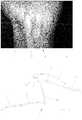
- Figure 1illustrates an image 1 of the inner side of a human wrist captured with a common CCD camera. It shows a pattern of blood vessels 30, in particular veins, clearly distinguishable among the surrounding tissues 31.
- this imageis a reproduction in the visible range of data captured with a near-infrared or temperature sensor.
- This patternconstitutes a unique feature of the person and could be compared with one or a plurality of reference patterns in order to identify or authenticate this person.
- FIG. 2illustrates a first embodiment of an apparatus according to the invention.
- the strap 12comprises a deployant flip clasp (or buckle) 4 with two articulated blades 10 which are superimposed or juxtaposed when the clasp is closed.
- One of the bladespreferably the lower blade 10 may comprise two parallel branches 100 with a window 101 between them in which the upper blade is inserted when the clasp is closed.
- a cover 11is connected to one blade on one side and to one branch of the strap on the other side. This cover covers at least partly the two blades 10 when the clasp is closed, and might comprise locking means for holding the clasp securely closed, or for opening it by acting on at least one button 110.
- a camera 3is mounted on a lateral side of the cover 11 and oriented toward the inner side of the wrist when the clasp is normally closed.
- This camera(as in all further embodiments) may comprise a CCD sensor for capturing images of the pattern of blood vessels in a near-infrared wavelength. The use of near-infrared wavelength makes the capture less sensitive to ambient light.
- a lens(not shown) may be provided in front of the camera 3 for controlling the size of the captured portion of wrist, and for focusing the image on the camera when the camera is at a suitable distance to the wrist. The focusing distance may be in a range between 10 and 80mm.
- the image of the wristmay be captured between the two branches 100 of the lower blade 10, and on both sides of this lower blade.
- the camera 3may be controlled for capturing a sequence of images from various distances and various orientations when the clasp is closed.
- the sequence of imagesmay comprise images of the inner side of the wrist, and/or images of at least some fingers and/or images of the palms; all those images may be captured when the clasp 4 is closed and while the camera is moved at a distance from the fingers, palm and/or wrist.
- the imagesmay be used for authenticating or identifying the user.
- the images of the wrist, palm and/or fingerspreferably include blood vessels of the wrist, palm and/or fingers, respectively.
- a computer vision software modulemay retain the suitable images in the sequence, for example the images which are focused and correctly oriented. Images of adjacent or overlapping portions of the fingers, palm and/or wrists may be stitched into a larger image. Successive images of a same area may be combined into a higher resolution, better focused, more dynamic and/or less noisy image of the area.
- Illuminating lights 15, for example near-infrared LEDs or OLEDs,may be provided on the cover 11 for illuminating the portion of wrist to be imaged.
- Various lights emitting in various wavelengths, for example near-infrared leds and visible light leds,may be provided in order to capture, simultaneously or sequentially, different images of a same portion of the body illuminated with different wavelengths.
- the skinis illuminated with light injected into a preferably flat light transmitive plate or foil acting as a light guide over or around or beneath the camera 3.
- a light source 15injects light into the plate, which is internally reflected against the upper and lower surfaces.
- the upper and lower surfaces of the plateare structured with a grating in order to control the inner reflexions at the interface between the plate and the air, so as to control the intensity of light which is internally reflected or scattered outside the plate to illuminate the skin.
- the platemay be flat or bended. The image of the skin may traverse the plate and reach the sensor.
- the illuminating sources 15are preferably arranged such that light emanating from the illuminating sources coincide at a depth 3mm below the surface of the skin to minimise back scatter into the photo diode array and to optimally illuminate the veins.
- the illuminating sources 15are switched to provide a series of differently illuminated images which is integrated into a combined image to improve vein rendition.
- the capture of a sequence of imagesmay be triggered by the user, for example by acting on one of the buttons 110 used for locking/unlocking the cover or on additional dedicated button.
- the action of triggering a capture of a sequence of imagesis provided by a pinch mechanism actuated by the finger and thumb on button 110 at both sides of the cover 11. Using the finger and thumb in this manner ensures that the camera is not inadvertently obscured as the image is taken.
- the capturemay be triggered automatically when the clasp 4 is closed.
- a galvanic contactis established during the folding of the blades, which triggers a capture.
- an inertial sensorsuch as an accelerometer detects the closure of the clasp and triggers the camera 3.
- Figure 3illustrates another embodiment of a flip clasp 4 with two blades 10 and one cover 11.
- the camera 3 and/or the lighting elements 15are mounted on the upper blade 10 in order to capture an image of the wrist through the window 101 between the two branches 100 of the lower blade 10, and on both sides of this lower blade.
- the camera 3may be equipped with a wide angle lens. It might be a near infrared camera. It might be equipped with an optical filter for blocking light outside of the near-infrared range.
- the sensorfurther comprises an integrated circuit (not shown), for example an ASIC, for controlling the camera 3 and processing the images captured with this camera.
- ASICan integrated circuit
- the ASIC, as well as a battery for powering the camera and the sensor,might be mounted within the cover 11. Alternatively, the sensor and camera might be powered from a smartwatch mounted on the strap 12.
- the lighting meansfor example near infrared LEDs may also be mounted below the cover 11.
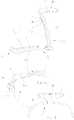
- FIGS 4a and 4billustrate a wrist strap 12 with a butterfly clasp 4, i.e. a clasp comprising a central blade 11 and two lateral blades 10, one lateral blade being articulated at each extremity of the central blade 11 so that each lateral blade may be folded under (or above) one half length of the central blade when the clasp is secured in a closed state.
- the camera 3(not shown) and the battery plus integrated circuit might be mounted into or below the central blade 11, with a focus distance of more than 10mm in order to capture a focused view when the central blade 11 is at one distance of more than 10 mm from the wrist, palm and/or fingers.
- Figure 5a and 5billustrate another example of wrist strap 12 with a deployant clasp 4 comprising seven blades 10; the central blade 10A includes the electronics, the battery and two cameras 3 for capturing an image of the wrist from a distance of more than 10mm. Lighting elements (not shown) may also be provided under the central blade 10A.
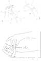
- Figures 6a and 6billustrate another example of wrist strap 12 with a clasp 4 comprising a cover 11 in two parts which can be moved against each other and secured together in a closed position.
- the two parts of the covermay be linked to each other by wires or cables 13 which are retracted into one part 11 when the cover is closed.
- the camera 3 and/or lighting elementsmay be provided below one part 11 of the cover, so that it will be laterally moved when the clasp is closed, thus scanning a large portion of the wrist, palm and/or fingers.
- Figure 7illustrates an example of a wrist watch comprising a case 14 for the watch movement and display, a strap 12 and a cover 11 having two cameras 3 and a lighting element 15 arranged for imaging the inner side of the wrist.
- the strap 12comprises a plurality of links 120 elastically connected to each other, so that the wrist watch can be put on.
- By enlarging the strap 12 as in Figure 10it is also possible to move the cameras 3 at a distance from the wrist, for example at a distance of more than 10mm, and to scroll it over the fingers, palm and wrist in order to image a larger portion of the fingers, palm and/or wrist.
- Another camera or blood vessel sensormight be provided below the cover of the watch 14.
- Figure 8illustrates another example of wrist watch with a strap 12 comprising two branches; a camera 3, and possibly a lighting system, is mounted at one extremity of one branch, in order to capture a focused image of the wrist, palm and/or fingers from a distance of more than 10 mm.
- Figures 9a and 9billustrate another example of a strap 12 with a clasp 4 comprising two blade 10 and a cover 11. Two cameras are provided under the cover 11, as well as possibly a lighting element (not shown).
- each embodimentcould comprise lighting means, for example near-infrared LEDs, and/or a wide-angle lens, and/or an optical filter such as a polarizing filter and/or a near-infrared filter and/or a diffuser.
- the camera 3is arranged for capturing focus image of the blood vessels underneath the skin when the camera is at a distance of more than 10mm, for example a distance of more than 20mm, typically a distance between 25 and 50mm.
- the lighting meanscould comprise LEDs that encircle the camera lens in a circular or rectangular configuration.
- the Ledsmay be mounted in a black or brown plastic diffuser.
- the reliability of the identification or authentication taskdepends on the number of distinguishing identification points in the captured image. Therefore, a high resolution image of a large portion of the user's wrist, preferably including portions of the palm and/or portions of the fingers,enables a more reliable recognition than a low resolution and/or small size image.
- a large size imagecould be captured with a large size sensor at a distance to the skin.
- the wristwatch and the sensorare preferably moved, for example slid, between each image in the series. This movement might be the natural movement of one part of the clasp which is required in order to close the clasp.
- the resolution of the different camerasmay be identical or different.
- an additional sensormay be provided on the back of the watch or on the inner side of the clasp or strap, for capturing images of the wrist from a close distance (less than 5mm, possibly 0mm) to the wrist.
- This additional sensormay be manufactured with organic electronic components, for example organic photodetectors, printed on a substrate, for example a bendable substrate, preferably a plastic substrate.
- Organic photodetectorsmay be printed on this substrate, for example using ink-jet or other digital printing technology. These photodetectors are adapted for capturing light reflected by the skin in one or a plurality of wavelengths, for example in the near-infrared range. Different photodetectors onto the same substrate may be adapted for detecting light in different wavelengths.
- the wristwatch or wristbandmay include a processor (not shown) for receiving the images from the sensor or sensors, possibly stitching those images, possibly detect spoofing attempts, and match those images with reference images in order to authenticate or identify the user.
- a processornot shown for receiving the images from the sensor or sensors, possibly stitching those images, possibly detect spoofing attempts, and match those images with reference images in order to authenticate or identify the user.
- a software modulecan be stored in a memory of the apparatus and executed by the processor for enhancing the contrast between the blood vessels and the rest of the image.
- a software modulecan be stored in a memory of the apparatus and executed by the processor for removing noise in the image produced by the sensor and/or by the contrast enhancing module.
- the different images produced at various wavelengthsmay be combined into a single image with more information. For example, the shadows and other area of an image in the visible wavelengths which are affected by the ambient light may be corrected with information from the infrared sensor which is less sensible to ambient light.
- the different images produced at different wavelengths rangesmay be compared individually to reference images; in this later case, a decision for the identification / authentication may depend on the results of all classifications at different wavelengths.
- the processormay further execute a module for matching a captured image with at least one reference image.
- features of the captured imageare compared with features of a reference image corresponding to an identity claimed by the user wearing the wrist band.
- This claimed identitymay be for example entered by inputting an identification, possibly with a password, possible on the display of a smartwatch including the sensor, with a device such as a computer, smartphone or tablet connected to the smartwatch.
- This identitymay be claimed for example each time a user starts his watch, or on demand each time he wants to access a protected application or web site for example.
- features of the reference imageare compared with features of one reference image stored in the smartwatch including the sensor, or in a smart card in this smartwatch.
- the reference imagemay be entered during an enrolment session for example when the user uses the sensor for the first time. In this case, the user does not need to claim his identity each time he needs to be authenticated with the biometric sensor; the role of the biometric sensor is mainly to make sure that the wrist band is worn by one authorised user.
- the biometric sensoris used for identifying the wearer of the band, by matching features of his biometric image with features of images corresponding to different users in order to identify which specific user has the wrist band.
- the identification or authenticationmay be performed each time the user starts his apparatus, for example when he puts his watch, when he logs on into the operating system of a smartwatch. It could be performed on demand when the user requests access to a protected application, function or web site for example. It could be performed continuously, or at regular intervals. A plurality of successive images may be used, for example in order to improve the quality and reliability, and/or to detect aliveness of the user and prevent spoofing.
- a first authenticationis performed when the user put his watch, and a new authentication or confirmation of the previous authentication is performed on request when the user requests access to a protected application, function or web site for example.
- the matching of imagesmay comprise a step of aligning them on topographical features. It might comprise a step of extracting features from the captured images, and comparing those features with corresponding features in reference images.
- the alignmentmay use the edges of the wrist, if both edges are visible. It may use the edges of the palm and/or fingers.
- a watch userwould place a watch with the sensor on his wrist and secure the clasp; he or she would then move the watch down to stop at the back of the hand where the width of the hand would stop further movement.
- This stoptriggers a change in an accelerometer which starts a clock signal.
- the userthen moves the watch up the wrist to stop at the point where the wrist thickens to prevent any further upward movement.
- the information from the sensoris written into a memory on each clock trigger to provide an image of the wrist, palm and/or fingers
Landscapes
- Engineering & Computer Science (AREA)
- Theoretical Computer Science (AREA)
- Multimedia (AREA)
- Physics & Mathematics (AREA)
- General Physics & Mathematics (AREA)
- Human Computer Interaction (AREA)
- Computer Security & Cryptography (AREA)
- Health & Medical Sciences (AREA)
- Signal Processing (AREA)
- Computer Hardware Design (AREA)
- Software Systems (AREA)
- General Engineering & Computer Science (AREA)
- Vascular Medicine (AREA)
- General Health & Medical Sciences (AREA)
- Toxicology (AREA)
- Measurement Of The Respiration, Hearing Ability, Form, And Blood Characteristics Of Living Organisms (AREA)
- Image Input (AREA)
Description
- The present invention concerns a biometric sensor for detection of wrist blood vessels in a wristwatch.
- Biometrics is widely used in order to authenticate or identify users. Biometrics is often based on fingerprint, voice, retina, iris, palm, face or wrist vessel recognition. The present application is related to biometric sensors used for authenticating or identifying users based on patterns of blood vessels in the wrist.
- The subcutaneous blood vessels on a human wrist can be imaged using infrared illumination and in particular, near infrared (NIR) illumination.
- This technology is disclosed, among other, in an article published by the New York Times and related to a smart card carrier that reads veins. The article is available at http://www.nytimes.com/1988/12/14/business/business-technology-a-card-that-sees-user-s-veins.html
- An oral presentation on this subject was also made byMr Joe Rice at the Biometric Summit in Washington, DC in January 1999. This lecture was subsequently published in theInformation Systems Audit and Control Associations Journal, and is available at https://groups.google.com/forum/#imsg/comp.society.privacy/gynQOQHXzmQ/6LpJ ubLOWmwJ.
- The web page"http://fingerchip.pagesperso-orange.fr/biometrics/types/vein JoeRice.htm" describe another aspects of vein pattern biometric and how it can be applied can be applied to safeguarding the individuals privacy and security.
US8019126B2 describes a biometric data acquisition device to be worn around the wrist. The device comprises a biometric acquisition unit for acquiring a vein pattern of a living body, and an authentication unit for performing personal authentication using the vein pattern acquired by the biometric acquisition unit. The biometric data acquisition unit includes a light source unit that emits illuminating light, such as a LED or a circular light source unit, and a light receiving unit such as a CCD device and micro lens arrays provided on one main surface of the circular basis of the wristwatch. This document does not describe the technology used to manufacture the light source unit and the CCD device. Conventional technology would result in a thick, flat device that is difficult to integrate in a wristwatch, especially in a flat wristwatch. Moreover, large CCDs which are required in order to scan a large area of the dorsal area of the wrist are expensive and power-consuming.US6799726B2 describes a wristwatch having a biometric sensor positioned so as to rest on the skin and detect the subcutaneous pattern or arteries, veins, capillaries and other blood vessels. The technology used to manufacture the sensor is not described.US7174032B2 describes an apparatus with a pickup section for picking up an image of a blood vessel pattern of a wrist. The pickup section is provided with a near-infrared LED an IR camera, such as a CCD camera. The apparatus is voluminous and intended to be integrated in a chair armrest.US4699149 discloses an apparatus for identifying an individual based on his detected blood vessels. The apparatus comprises infra-red radiation emitting diodes and reflecting radiations sensing means.US20140196131 discloses a wearable wrist vein pattern device for authentication applications. The wrist device comprises illuminators, such as LEDs or VCSELs Lasers, and an array of wrist contact sensors, e.g. CCD sensors.EP2328111 describes a biometric pattern detecting method and device adapted to detect subcutaneous blood vessels for authentication applications. The device exploits optical, electrical and/or temperature discriminants between epidermal tissue and deep-layer tissue of the skin. In one embodiment, tissue structures are established by a plurality of temperature detecting devices arrayed upon the skin. A two-dimensional array of detecting temperature devices, e.g. thermistor, bolometers, thermopiles, is arranged to detect epidermal layer temperatures.- A problem common to those prior art devices is their thickness which make them difficult to integrate in a wristwatch or bracelet for a wristwatch.
- Another problem is the cost of designing and manufacturing sensors in various different dimensions. Wristwatches and bracelets exist in a large variety of sizes and forms, and it would be desirable to adapt the size and form of the sensor to each specific design. However, the cost of producing small series of devices using conventional photolithography technologies is prohibitive.
- Another problem is the small size of the area which can be imaged with an infrared sensor that rests directly on the skin. The area is limited by the surface of the back of the watch in contact with the skin, usually a circle with a diameter of 42mm or less. This surface is insufficient for capturing a pattern of blood vessels large enough to perform a reliable authentication. Moreover, wristwatches do not always rest on the same area of the wrist, but are often held relatively loosely so that they can rotate and slide along the wrist. Therefore, the reference pattern of blood vessels and the test pattern often correspond to different areas of the wrist, resulting in many legitimate users being rejected.
- Most conventional solutions are integrated in the back of a wristwatch and therefore intended for capturing patterns of blood vessels on the dorsal side of a wrist. This dorsal side is however poorly irrigated and contains less vessels than the inner side of the wrist. Therefore, the authentication is based on a matching between limited number of vessels, and therefore not very reliable.
- It is therefore an aim of the invention to provide an apparatus that solves or mitigates the problems of those prior art solutions as e.g. disclosed in
US2010/0237990 . - According to the invention, these aims are achieved by means of a biometric sensor apparatus according to
claim 1 and a method according to claim 16. - The apparatus may be for example a wristwatch, a wrist strap (bracelet), etc.
- In this application, the expression "image" should be given a broad meaning so as to encompass different concepts. An image could be a picture or reproduction, for example on paper or on a display. An image could be data corresponding to such a reproduction, for example a file such as a tif file, a jpeg file etc. An image could correspond to a visible phenomenon, for example a reproduction in a visible range of what a human or visible length sensor would see, or to something not visible, for example data or reproduction of values captured by a sensor such as an infrared sensor, a near-infrared sensor, a temperature sensor, etc
- The camera is provided on the inner side of a portion of the wrist strap and could thus be used to identify a user when accessing applications and/or web sites with a smartwatch mounted onto said strap, for example, or with a computer, mobile phone or tablet connected with this strap. The identification is thus provided by a proof of possession of an object (the wrist strap) and by biometric features.
- By capturing images when the inner side is at a distance from the wrist, for example at a distance of more than 10mm, for example more than 20mm, it is possible to capture a relatively large area of the wrist. This makes the matching with reference images more reliable, since it could be based on a larger network of blood vessels and larger number of features. Moreover, it is more likely that a sufficient portion of the captured image will correspond to a portion of a corresponding reference image.
- Capturing images from a distance also makes the illumination easier, since a relatively large portion of the inner side of the wrist could be illuminated with an illuminating unit for illuminating a portion of said inner side.
- The sensor may be mounted on a deployant clasp of the strap.
- The deployant clasp may comprise a plurality of blades overlapped when the clasp is closed and juxtaposed when the clasp is deployed. The clasp may be a butterfly clasp, a flip clasp, a diapason clasp, etc. It may comprise two or three blades.
- The camera may be mounted onto one of said blades.
- The clasp may comprise a cover over the blades. The cover may house the camera.
- At least one of the blades may comprise a window, for example an opening between two parallel branches of the blade. The camera may be arranged for capturing an image of the blood vessel pattern through this window.
- A camera may be mounted on the lower (inner) side of the clasp.
- A camera may be mounted on a lateral side of said clasp, and oriented toward the inner side of the wrist when the clasp is secured.
- The wrist strap may be elastic in order to increase the distance between said camera and said wrist temporarily during the capture.
- The apparatus may comprise a button for triggering the capture when the user activates said button. This button may also be used to open and/or to close the clasp.
- The apparatus may be arranged for automatically triggering a capture when a user closes the wrist strap, for example when he closes the clasp.
- In one example, the apparatus includes an accelerometer for automatically triggering a capture when a closure movement is detected.
- The apparatus may be arranged for automatically capturing a sequence of images of blood vessel patterns when a user closes said wrist strap or when a user activates a capture.
- The apparatus may further comprise a computer vision software module for analysing sequences of images captured with the camera at various distances and/or orientation relative to the wrist, and selecting at least one image comprising a desired portion of the wrist. In one embodiment, the capture of a sequence is triggered manually by the user, or automatically when the clasp is secured. Among those successive images in the sequence, only those which are focused and pointed at a relevant portion of the wrist are used for the authentication or identification process.
- The apparatus may comprise a plurality of cameras, each of said cameras being arranged for capturing a plurality of sequences of images of said wrist.
- The apparatus may comprise a processor for processing data measured by said sensor in order to identify or authenticate a user.
- The apparatus may comprise a software module executable by a processor for causing said processor to stitch a plurality of images of different portions of the wrist, for example successive images from one camera, and/or images captured with different cameras.
- The invention will be better understood with the aid of the description of an embodiment given by way of example and illustrated by the figures, in which:
Fig. 1 shows an image of a pattern of blood vessels in a human wrist.Fig. 2 is a side view of a first embodiment of an apparatus according to a first embodiment of the invention.Fig. 3 is a top view of a second embodiment of an apparatus according to the invention.Fig. 4a and 4b are a perspective and side view of a third embodiment of an apparatus according to the invention.Fig. 5a and 5b are two isometric views of a fourth embodiment of an apparatus according to the invention.Fig. 6a and 6b are two an isometric views of a fifth embodiment of an apparatus according to the invention.Fig. 7 is an isometric view of a sixth embodiment of an apparatus according to the invention.Fig. 8 is an isometric view of a seventh embodiment of an apparatus according to the invention.Figures 9a and 9b are two isometric views of an eighth embodiment of an apparatus according to the invention, in an open respectively closed state.Figure 10 illustrates how a sequence of images may be captured when the strap is moved with a camera at a distance from the wrist.Figure 1 illustrates animage 1 of the inner side of a human wrist captured with a common CCD camera. It shows a pattern ofblood vessels 30, in particular veins, clearly distinguishable among the surroundingtissues 31. In one example, this image is a reproduction in the visible range of data captured with a near-infrared or temperature sensor. This pattern constitutes a unique feature of the person and could be compared with one or a plurality of reference patterns in order to identify or authenticate this person.Figure 2 illustrates a first embodiment of an apparatus according to the invention. In this embodiment, thestrap 12 comprises a deployant flip clasp (or buckle) 4 with two articulatedblades 10 which are superimposed or juxtaposed when the clasp is closed. One of the blades, preferably thelower blade 10, may comprise twoparallel branches 100 with awindow 101 between them in which the upper blade is inserted when the clasp is closed. Acover 11 is connected to one blade on one side and to one branch of the strap on the other side. This cover covers at least partly the twoblades 10 when the clasp is closed, and might comprise locking means for holding the clasp securely closed, or for opening it by acting on at least onebutton 110.- A
camera 3 is mounted on a lateral side of thecover 11 and oriented toward the inner side of the wrist when the clasp is normally closed. This camera (as in all further embodiments) may comprise a CCD sensor for capturing images of the pattern of blood vessels in a near-infrared wavelength. The use of near-infrared wavelength makes the capture less sensitive to ambient light. A lens (not shown) may be provided in front of thecamera 3 for controlling the size of the captured portion of wrist, and for focusing the image on the camera when the camera is at a suitable distance to the wrist. The focusing distance may be in a range between 10 and 80mm. - The image of the wrist may be captured between the two
branches 100 of thelower blade 10, and on both sides of this lower blade. - The
camera 3 may be controlled for capturing a sequence of images from various distances and various orientations when the clasp is closed. As illustrated withFigure 10 , the sequence of images may comprise images of the inner side of the wrist, and/or images of at least some fingers and/or images of the palms; all those images may be captured when theclasp 4 is closed and while the camera is moved at a distance from the fingers, palm and/or wrist. The images may be used for authenticating or identifying the user. The images of the wrist, palm and/or fingers preferably include blood vessels of the wrist, palm and/or fingers, respectively. - A computer vision software module may retain the suitable images in the sequence, for example the images which are focused and correctly oriented. Images of adjacent or overlapping portions of the fingers, palm and/or wrists may be stitched into a larger image. Successive images of a same area may be combined into a higher resolution, better focused, more dynamic and/or less noisy image of the area.
- Illuminating
lights 15, for example near-infrared LEDs or OLEDs, may be provided on thecover 11 for illuminating the portion of wrist to be imaged. Various lights emitting in various wavelengths, for example near-infrared leds and visible light leds, may be provided in order to capture, simultaneously or sequentially, different images of a same portion of the body illuminated with different wavelengths. - In one embodiment, the skin is illuminated with light injected into a preferably flat light transmitive plate or foil acting as a light guide over or around or beneath the
camera 3. Alight source 15 injects light into the plate, which is internally reflected against the upper and lower surfaces. The upper and lower surfaces of the plate are structured with a grating in order to control the inner reflexions at the interface between the plate and the air, so as to control the intensity of light which is internally reflected or scattered outside the plate to illuminate the skin. The plate may be flat or bended. The image of the skin may traverse the plate and reach the sensor. - The illuminating
sources 15 are preferably arranged such that light emanating from the illuminating sources coincide at a depth 3mm below the surface of the skin to minimise back scatter into the photo diode array and to optimally illuminate the veins. - In one embodiment, the illuminating
sources 15 are switched to provide a series of differently illuminated images which is integrated into a combined image to improve vein rendition. - The capture of a sequence of images may be triggered by the user, for example by acting on one of the
buttons 110 used for locking/unlocking the cover or on additional dedicated button. In one embodiment, the action of triggering a capture of a sequence of images is provided by a pinch mechanism actuated by the finger and thumb onbutton 110 at both sides of thecover 11. Using the finger and thumb in this manner ensures that the camera is not inadvertently obscured as the image is taken. - Alternatively, or in addition, the capture may be triggered automatically when the
clasp 4 is closed. In one example, a galvanic contact is established during the folding of the blades, which triggers a capture. In another embodiment, an inertial sensor (not shown) such as an accelerometer detects the closure of the clasp and triggers thecamera 3. Figure 3 illustrates another embodiment of aflip clasp 4 with twoblades 10 and onecover 11. In this example, thecamera 3 and/or thelighting elements 15 are mounted on theupper blade 10 in order to capture an image of the wrist through thewindow 101 between the twobranches 100 of thelower blade 10, and on both sides of this lower blade. Thecamera 3 may be equipped with a wide angle lens. It might be a near infrared camera. It might be equipped with an optical filter for blocking light outside of the near-infrared range.- The sensor further comprises an integrated circuit (not shown), for example an ASIC, for controlling the
camera 3 and processing the images captured with this camera. The ASIC, as well as a battery for powering the camera and the sensor, might be mounted within thecover 11. Alternatively, the sensor and camera might be powered from a smartwatch mounted on thestrap 12. - The lighting means, for example near infrared LEDs may also be mounted below the
cover 11. Figures 4a and 4b illustrate awrist strap 12 with abutterfly clasp 4, i.e. a clasp comprising acentral blade 11 and twolateral blades 10, one lateral blade being articulated at each extremity of thecentral blade 11 so that each lateral blade may be folded under (or above) one half length of the central blade when the clasp is secured in a closed state. The camera 3 (not shown) and the battery plus integrated circuit might be mounted into or below thecentral blade 11, with a focus distance of more than 10mm in order to capture a focused view when thecentral blade 11 is at one distance of more than 10 mm from the wrist, palm and/or fingers.Figure 5a and 5b illustrate another example ofwrist strap 12 with adeployant clasp 4 comprising sevenblades 10; thecentral blade 10A includes the electronics, the battery and twocameras 3 for capturing an image of the wrist from a distance of more than 10mm. Lighting elements (not shown) may also be provided under thecentral blade 10A.Figures 6a and 6b illustrate another example ofwrist strap 12 with aclasp 4 comprising acover 11 in two parts which can be moved against each other and secured together in a closed position. The two parts of the cover may be linked to each other by wires orcables 13 which are retracted into onepart 11 when the cover is closed. Thecamera 3 and/or lighting elements (not shown) may be provided below onepart 11 of the cover, so that it will be laterally moved when the clasp is closed, thus scanning a large portion of the wrist, palm and/or fingers.Figure 7 illustrates an example of a wrist watch comprising acase 14 for the watch movement and display, astrap 12 and acover 11 having twocameras 3 and alighting element 15 arranged for imaging the inner side of the wrist. Thestrap 12 comprises a plurality oflinks 120 elastically connected to each other, so that the wrist watch can be put on. By enlarging thestrap 12 as inFigure 10 , it is also possible to move thecameras 3 at a distance from the wrist, for example at a distance of more than 10mm, and to scroll it over the fingers, palm and wrist in order to image a larger portion of the fingers, palm and/or wrist. Another camera or blood vessel sensor might be provided below the cover of thewatch 14.Figure 8 illustrates another example of wrist watch with astrap 12 comprising two branches; acamera 3, and possibly a lighting system, is mounted at one extremity of one branch, in order to capture a focused image of the wrist, palm and/or fingers from a distance of more than 10 mm.Figures 9a and 9b illustrate another example of astrap 12 with aclasp 4 comprising twoblade 10 and acover 11. Two cameras are provided under thecover 11, as well as possibly a lighting element (not shown).- Features of the various embodiments could be combined. For example, it is possible to have a plurality of cameras in each of the described embodiments. Each embodiment could comprise lighting means, for example near-infrared LEDs, and/or a wide-angle lens, and/or an optical filter such as a polarizing filter and/or a near-infrared filter and/or a diffuser. In each embodiment, the
camera 3 is arranged for capturing focus image of the blood vessels underneath the skin when the camera is at a distance of more than 10mm, for example a distance of more than 20mm, typically a distance between 25 and 50mm. - The lighting means could comprise LEDs that encircle the camera lens in a circular or rectangular configuration. The Leds may be mounted in a black or brown plastic diffuser.
- The reliability of the identification or authentication task depends on the number of distinguishing identification points in the captured image. Therefore, a high resolution image of a large portion of the user's wrist, preferably including portions of the palm and/or portions of the fingers,enables a more reliable recognition than a low resolution and/or small size image. A large size image could be captured with a large size sensor at a distance to the skin. Alternatively, it is also possible to capture a series of images of adjacent portions of the wrist, palm and/or fingers, and to assemble or stitch those successive images into a large size image corresponding to a larger portion of the wrist, palm and/or fingers. The wristwatch and the sensor are preferably moved, for example slid, between each image in the series. This movement might be the natural movement of one part of the clasp which is required in order to close the clasp.
- It is also possible to increase the size of the captured portion by using a plurality of cameras. The resolution of the different cameras may be identical or different.
- In one example, an additional sensor may be provided on the back of the watch or on the inner side of the clasp or strap, for capturing images of the wrist from a close distance (less than 5mm, possibly 0mm) to the wrist. This additional sensor may be manufactured with organic electronic components, for example organic photodetectors, printed on a substrate, for example a bendable substrate, preferably a plastic substrate. Organic photodetectors may be printed on this substrate, for example using ink-jet or other digital printing technology. These photodetectors are adapted for capturing light reflected by the skin in one or a plurality of wavelengths, for example in the near-infrared range. Different photodetectors onto the same substrate may be adapted for detecting light in different wavelengths.
- The wristwatch or wristband may include a processor (not shown) for receiving the images from the sensor or sensors, possibly stitching those images, possibly detect spoofing attempts, and match those images with reference images in order to authenticate or identify the user.
- A software module can be stored in a memory of the apparatus and executed by the processor for enhancing the contrast between the blood vessels and the rest of the image.
- A software module can be stored in a memory of the apparatus and executed by the processor for removing noise in the image produced by the sensor and/or by the contrast enhancing module.
- The different images produced at various wavelengths may be combined into a single image with more information. For example, the shadows and other area of an image in the visible wavelengths which are affected by the ambient light may be corrected with information from the infrared sensor which is less sensible to ambient light. Alternatively, the different images produced at different wavelengths ranges may be compared individually to reference images; in this later case, a decision for the identification / authentication may depend on the results of all classifications at different wavelengths.
- The processor may further execute a module for matching a captured image with at least one reference image. In one embodiment, features of the captured image are compared with features of a reference image corresponding to an identity claimed by the user wearing the wrist band. This claimed identity may be for example entered by inputting an identification, possibly with a password, possible on the display of a smartwatch including the sensor, with a device such as a computer, smartphone or tablet connected to the smartwatch. This identity may be claimed for example each time a user starts his watch, or on demand each time he wants to access a protected application or web site for example.
- Alternatively, features of the reference image are compared with features of one reference image stored in the smartwatch including the sensor, or in a smart card in this smartwatch. The reference image may be entered during an enrolment session for example when the user uses the sensor for the first time. In this case, the user does not need to claim his identity each time he needs to be authenticated with the biometric sensor; the role of the biometric sensor is mainly to make sure that the wrist band is worn by one authorised user.
- In another embodiment, the biometric sensor is used for identifying the wearer of the band, by matching features of his biometric image with features of images corresponding to different users in order to identify which specific user has the wrist band.
- The identification or authentication may be performed each time the user starts his apparatus, for example when he puts his watch, when he logs on into the operating system of a smartwatch. It could be performed on demand when the user requests access to a protected application, function or web site for example. It could be performed continuously, or at regular intervals. A plurality of successive images may be used, for example in order to improve the quality and reliability, and/or to detect aliveness of the user and prevent spoofing. In one embodiment, a first authentication is performed when the user put his watch, and a new authentication or confirmation of the previous authentication is performed on request when the user requests access to a protected application, function or web site for example.
- The matching of images may comprise a step of aligning them on topographical features. It might comprise a step of extracting features from the captured images, and comparing those features with corresponding features in reference images.
- The alignment may use the edges of the wrist, if both edges are visible. It may use the edges of the palm and/or fingers.
- In one example of use, a watch user would place a watch with the sensor on his wrist and secure the clasp; he or she would then move the watch down to stop at the back of the hand where the width of the hand would stop further movement. This stop triggers a change in an accelerometer which starts a clock signal. The user then moves the watch up the wrist to stop at the point where the wrist thickens to prevent any further upward movement. As this movement is taking place the information from the sensor is written into a memory on each clock trigger to provide an image of the wrist, palm and/or fingers
Claims (16)
- A biometric sensor apparatus for capturing images (1) of patterns of blood vessels (30) on the inner side of a wrist, comprising:a wrist strap (12); anda near infrared camera (3) for capturing said images;said camera being mounted on a portion of the wrist strap and oriented towards the inner side of the wrist;and means to activate the capturing of said images;characterized in that:
said portion of said wrist strap comprises multiple components which remain connected together in a retractable way or in a foldable way to provide an open position and a closed position, said camera being mounted on one of the components facing the wrist in the open position of the wrist strap and arranged to capture said images. - The apparatus according to claim 1, wherein the wrist strap (12) comprises a clasp (4) having a cover (11) in two parts which can be moved against each other and secured together in the closed position, the two parts being linked to each other by wires or cables (13) which are retractable into one part (11) when the cover is closed, the camera being provided below one part (11) of the cover.
- The apparatus according to claim 1, the wrist strap (12) comprising a deployant clasp (4) comprising two articulated blades (10) overlapped when the clasp is closed and juxtaposed when the clasp is deployed and a cover (11) which at least partly covers the blades (10) when the clasp (4) is closed, the camera (3) being mounted on the cover (11).
- The apparatus according to claim 1, the wrist strap (12) comprising a deployant clasp (4) comprising a plurality of articulated blades (10, 10A, 11) overlapped when the clasp is closed and juxtaposed when the clasp is deployed, the camera being mounted on one of said blades.
- The apparatus of any of the preceding claims, further comprising a lens for controlling the size of the captured portion of wrist and for focusing the image on the camera.
- The apparatus of any of the preceding claims, further comprising an illuminating unit (15) for illuminating a portion of said inner side.
- The apparatus of claim 6, said illuminating unit comprising a light transmitive plate or foil acting as a light guide over or around or beneath said camera (3), and a light source for emitting light into said plate or foil.
- The apparatus of one of the claims 3 to 7, at least one of said blades (10) comprising a window (101), said camera (3) being arranged for capturing an image (1) of said patterns through said window.
- The apparatus of one of the claims 3 to 8, said camera (3) being mounted on the lower side of said clasp.
- The apparatus of one of the claims 3 to 8, said camera (3) being mounted on a lateral side of said clasp.
- The apparatus of one of the claims 1 to 10, further comprising a button (110) for triggering said capture when said user activates said button.
- The apparatus of one of the claims 1 to 11, being arranged for automatically capturing a sequence of images when a user closes said wrist strap or when a user activates a capture.
- The apparatus of one of the claims 11 to 12, further comprising a computer vision software module for analysing sequences of images captured with said camera (3) at various distances and/or orientation relative to the wrist, and selecting at least one image comprising a desired portion of the wrist.
- The apparatus of any of the claims 1 to 13, comprising a plurality of cameras (3), each of said cameras being arranged for capturing a plurality of sequences of images of said wrist.
- The apparatus of any of the claims 1 to 14, further comprising a processor and a software module executable by said processor for causing said processor to stitch images of different portions of the wrist.
- A method for identifying a user of a biometric sensor apparatus according to claim 1, comprising:
capturing a sequence of images of the inner side of the wrist and/or at least some fingers and/or at least one palm of the user while said portion of said wrist strap is in the open position and the camera is moved, at a distance, over said wrist, fingers or palm when the user activates said capture.
Priority Applications (3)
| Application Number | Priority Date | Filing Date | Title |
|---|---|---|---|
| EP15161422.9AEP3073414B1 (en) | 2015-03-27 | 2015-03-27 | A biometric sensor for detection of wrist blood vessels in a wrist strap |
| US15/046,187US9996758B2 (en) | 2015-03-27 | 2016-02-17 | Biometric sensor for detection of wrist blood vessels in a wrist strap |
| JP2016043567AJP6767755B2 (en) | 2015-03-27 | 2016-03-07 | Biometric sensor that detects blood vessels in the wrist on the wrist strap |
Applications Claiming Priority (1)
| Application Number | Priority Date | Filing Date | Title |
|---|---|---|---|
| EP15161422.9AEP3073414B1 (en) | 2015-03-27 | 2015-03-27 | A biometric sensor for detection of wrist blood vessels in a wrist strap |
Publications (2)
| Publication Number | Publication Date |
|---|---|
| EP3073414A1 EP3073414A1 (en) | 2016-09-28 |
| EP3073414B1true EP3073414B1 (en) | 2019-07-24 |
Family
ID=52774146
Family Applications (1)
| Application Number | Title | Priority Date | Filing Date |
|---|---|---|---|
| EP15161422.9AActiveEP3073414B1 (en) | 2015-03-27 | 2015-03-27 | A biometric sensor for detection of wrist blood vessels in a wrist strap |
Country Status (3)
| Country | Link |
|---|---|
| US (1) | US9996758B2 (en) |
| EP (1) | EP3073414B1 (en) |
| JP (1) | JP6767755B2 (en) |
Families Citing this family (14)
| Publication number | Priority date | Publication date | Assignee | Title |
|---|---|---|---|---|
| EP4588433A3 (en)* | 2013-11-29 | 2025-07-30 | Ouraring Inc. | Wearable computing device |
| WO2016040687A1 (en)* | 2014-09-10 | 2016-03-17 | Duo Watches Corporation | Multi-watch band |
| US20160183852A1 (en)* | 2014-12-26 | 2016-06-30 | Priya E. JOSEPH | System and method for determining a state of a body |
| WO2016196411A1 (en) | 2015-05-30 | 2016-12-08 | Jordan Frank | Electronic utility strap |
| WO2016197020A1 (en)* | 2015-06-05 | 2016-12-08 | Strebe Matthew | Multiple device wrist band |
| EP3118762B1 (en)* | 2015-07-15 | 2020-03-11 | Biowatch SA | Method, device and computer program for authenticating a user |
| JP6172341B2 (en)* | 2016-01-04 | 2017-08-02 | オムロンヘルスケア株式会社 | Biological information measuring device |
| US10331083B1 (en)* | 2016-09-16 | 2019-06-25 | Apple Inc. | Watch band with optical sensor |
| WO2018138067A1 (en)* | 2017-01-24 | 2018-08-02 | Smart Secure Id In Sweden Ab | Wearable biometric data acquisition device |
| KR20180129133A (en)* | 2017-05-25 | 2018-12-05 | 전자부품연구원 | 3D MSP-based Biometric Device and Method |
| US10867159B2 (en) | 2018-03-09 | 2020-12-15 | Apple Inc. | Electronic device including palm biometric sensor layer and related methods |
| USD912830S1 (en)* | 2018-06-18 | 2021-03-09 | Oxitone Medical Ltd. | Sensors case for watch |
| EP3832405A1 (en)* | 2019-12-06 | 2021-06-09 | Tissot S.A. | Watch comprising a system for controlling biometric access to confidential data |
| US11308744B1 (en)* | 2019-12-27 | 2022-04-19 | Jimcy Exantus | Wrist-wearable tracking and monitoring device |
Family Cites Families (22)
| Publication number | Priority date | Publication date | Assignee | Title |
|---|---|---|---|---|
| WO1985004088A1 (en) | 1984-03-20 | 1985-09-26 | Joseph Rice | Method and apparatus for the identification of individuals |
| DE10001929A1 (en)* | 2000-01-19 | 2001-08-09 | Skidata Ag | Authorization control facility |
| JP4039039B2 (en) | 2001-11-08 | 2008-01-30 | ソニー株式会社 | Personal authentication device |
| EP2098977B1 (en) | 2002-05-09 | 2012-11-21 | Sony Corporation | Method of detecting biological pattern, biological pattern detector, method of biological certificate and biological certificate apparatus |
| JP4387643B2 (en)* | 2002-07-31 | 2009-12-16 | 富士通株式会社 | Processing device with personal recognition function |
| JP2006048667A (en)* | 2004-07-08 | 2006-02-16 | Universal Robot Kk | Personal authentication device, robot controller using the same, authentication method and robot control method using the same |
| US20060288233A1 (en)* | 2005-04-25 | 2006-12-21 | Douglas Kozlay | Attachable biometric authentication apparatus for watchbands and other personal items |
| JP4863793B2 (en)* | 2005-07-12 | 2012-01-25 | シスメックス株式会社 | Non-invasive living body measurement device |
| WO2007115570A1 (en)* | 2006-04-07 | 2007-10-18 | Novarix Ltd | Vein navigation device |
| JP4308220B2 (en)* | 2006-04-24 | 2009-08-05 | 富士通株式会社 | Personal recognition device |
| JP5352960B2 (en) | 2006-04-27 | 2013-11-27 | セイコーエプソン株式会社 | Biometric information acquisition apparatus, biometric information acquisition method, and biometric authentication apparatus |
| EP1905351B1 (en)* | 2006-09-29 | 2016-10-26 | Sysmex Corporation | Nonivasive living body measuring device and noninvasive living body measuring method |
| JP5010368B2 (en)* | 2007-06-29 | 2012-08-29 | シスメックス株式会社 | Non-invasive blood component measurement method and non-invasive blood component measurement device |
| EP2172154A4 (en)* | 2007-07-31 | 2013-09-25 | Sysmex Corp | Noninvasive biometric device and noninvasive biometric method |
| JP5274829B2 (en)* | 2007-12-27 | 2013-08-28 | シスメックス株式会社 | Non-invasive living body measurement device |
| JP2010211756A (en)* | 2009-03-12 | 2010-09-24 | Seiko Epson Corp | Apparatus, and method for obtaining biological information, and biometric authentication apparatus |
| US20130314303A1 (en)* | 2010-02-28 | 2013-11-28 | Osterhout Group, Inc. | Ar glasses with user action control of and between internal and external applications with feedback |
| US8954135B2 (en)* | 2012-06-22 | 2015-02-10 | Fitbit, Inc. | Portable biometric monitoring devices and methods of operating same |
| US20140196131A1 (en) | 2013-01-07 | 2014-07-10 | Salutron, Inc. | User authentication based on a wrist vein pattern |
| WO2014147713A1 (en)* | 2013-03-18 | 2014-09-25 | 株式会社 東芝 | Electronic device and authentication control method |
| US10478127B2 (en)* | 2014-06-23 | 2019-11-19 | Sherlock Solutions, LLC | Apparatuses, methods, processes, and systems related to significant detrimental changes in health parameters and activating lifesaving measures |
| US10463141B2 (en)* | 2014-07-01 | 2019-11-05 | Heloisa Fitzgerald Jewelry | Wearable modular electronic device, such as to hold a selectable and/or replaceable biometric sensor in close proximity to and/or in physical contact with a wearer and/or to hold a battery |
- 2015
- 2015-03-27EPEP15161422.9Apatent/EP3073414B1/enactiveActive
- 2016
- 2016-02-17USUS15/046,187patent/US9996758B2/ennot_activeExpired - Fee Related
- 2016-03-07JPJP2016043567Apatent/JP6767755B2/ennot_activeExpired - Fee Related
Non-Patent Citations (1)
| Title |
|---|
| None* |
Also Published As
| Publication number | Publication date |
|---|---|
| US20160283809A1 (en) | 2016-09-29 |
| JP2016189186A (en) | 2016-11-04 |
| US9996758B2 (en) | 2018-06-12 |
| JP6767755B2 (en) | 2020-10-14 |
| EP3073414A1 (en) | 2016-09-28 |
Similar Documents
| Publication | Publication Date | Title |
|---|---|---|
| EP3118764B1 (en) | A biometric sensor apparatus for authenticating a user, and a user authenticating method | |
| EP3073414B1 (en) | A biometric sensor for detection of wrist blood vessels in a wrist strap | |
| US11036844B2 (en) | Wearable electronic device having a light field camera | |
| US10360431B2 (en) | Electronic device including pin hole array mask above optical image sensor and related methods | |
| US10528834B2 (en) | Biometric sensor for detection of wrist blood vessels in a wristwatch or wristband | |
| US10282582B2 (en) | Finger biometric sensor for generating three dimensional fingerprint ridge data and related methods | |
| KR101255855B1 (en) | Personal identification device and method | |
| US8803963B2 (en) | Vein pattern recognition based biometric system and methods thereof | |
| US9491171B2 (en) | System and method for vascular mapping authentication | |
| JP6134662B2 (en) | Biometric authentication device and biometric authentication method | |
| US20150062319A1 (en) | Authentication apparatus, prism member for authentication and authentication method | |
| WO2016036456A1 (en) | Swipe motion registration on a fingerprint sensor | |
| JP2007219625A (en) | Blood vessel image input device and personal authentication system | |
| JP5811386B2 (en) | Authentication device, authentication prism body, and authentication method | |
| JP5811385B2 (en) | Authentication device, authentication prism body, and authentication method | |
| JP2006285487A (en) | Biometric information detection apparatus and biometric authentication apparatus | |
| KR101547659B1 (en) | A finger vein recognition apparatus and a terminal with the same | |
| JP6862739B2 (en) | Biographer and multifunctional clock | |
| Bhattacharyya et al. | Biometric authentication using infrared imaging of hand vein patterns | |
| KR20120076985A (en) | Finger vein authentication device using multi-wavelength |
Legal Events
| Date | Code | Title | Description |
|---|---|---|---|
| PUAI | Public reference made under article 153(3) epc to a published international application that has entered the european phase | Free format text:ORIGINAL CODE: 0009012 | |
| AK | Designated contracting states | Kind code of ref document:A1 Designated state(s):AL AT BE BG CH CY CZ DE DK EE ES FI FR GB GR HR HU IE IS IT LI LT LU LV MC MK MT NL NO PL PT RO RS SE SI SK SM TR | |
| AX | Request for extension of the european patent | Extension state:BA ME | |
| STAA | Information on the status of an ep patent application or granted ep patent | Free format text:STATUS: REQUEST FOR EXAMINATION WAS MADE | |
| 17P | Request for examination filed | Effective date:20170327 | |
| RBV | Designated contracting states (corrected) | Designated state(s):AL AT BE BG CH CY CZ DE DK EE ES FI FR GB GR HR HU IE IS IT LI LT LU LV MC MK MT NL NO PL PT RO RS SE SI SK SM TR | |
| STAA | Information on the status of an ep patent application or granted ep patent | Free format text:STATUS: EXAMINATION IS IN PROGRESS | |
| 17Q | First examination report despatched | Effective date:20171122 | |
| RAP1 | Party data changed (applicant data changed or rights of an application transferred) | Owner name:BIOWATCH SA | |
| RAP1 | Party data changed (applicant data changed or rights of an application transferred) | Owner name:BIOWATCH SA | |
| GRAP | Despatch of communication of intention to grant a patent | Free format text:ORIGINAL CODE: EPIDOSNIGR1 | |
| STAA | Information on the status of an ep patent application or granted ep patent | Free format text:STATUS: GRANT OF PATENT IS INTENDED | |
| INTG | Intention to grant announced | Effective date:20190424 | |
| GRAS | Grant fee paid | Free format text:ORIGINAL CODE: EPIDOSNIGR3 | |
| GRAA | (expected) grant | Free format text:ORIGINAL CODE: 0009210 | |
| STAA | Information on the status of an ep patent application or granted ep patent | Free format text:STATUS: THE PATENT HAS BEEN GRANTED | |
| AK | Designated contracting states | Kind code of ref document:B1 Designated state(s):AL AT BE BG CH CY CZ DE DK EE ES FI FR GB GR HR HU IE IS IT LI LT LU LV MC MK MT NL NO PL PT RO RS SE SI SK SM TR | |
| REG | Reference to a national code | Ref country code:GB Ref legal event code:FG4D | |
| REG | Reference to a national code | Ref country code:CH Ref legal event code:EP | |
| REG | Reference to a national code | Ref country code:DE Ref legal event code:R096 Ref document number:602015034140 Country of ref document:DE | |
| REG | Reference to a national code | Ref country code:AT Ref legal event code:REF Ref document number:1159078 Country of ref document:AT Kind code of ref document:T Effective date:20190815 | |
| REG | Reference to a national code | Ref country code:IE Ref legal event code:FG4D | |
| REG | Reference to a national code | Ref country code:NL Ref legal event code:MP Effective date:20190724 | |
| REG | Reference to a national code | Ref country code:LT Ref legal event code:MG4D | |
| REG | Reference to a national code | Ref country code:CH Ref legal event code:NV Representative=s name:OMNIS-IP SA, CH | |
| REG | Reference to a national code | Ref country code:AT Ref legal event code:MK05 Ref document number:1159078 Country of ref document:AT Kind code of ref document:T Effective date:20190724 | |
| PG25 | Lapsed in a contracting state [announced via postgrant information from national office to epo] | Ref country code:FI Free format text:LAPSE BECAUSE OF FAILURE TO SUBMIT A TRANSLATION OF THE DESCRIPTION OR TO PAY THE FEE WITHIN THE PRESCRIBED TIME-LIMIT Effective date:20190724 Ref country code:SE Free format text:LAPSE BECAUSE OF FAILURE TO SUBMIT A TRANSLATION OF THE DESCRIPTION OR TO PAY THE FEE WITHIN THE PRESCRIBED TIME-LIMIT Effective date:20190724 Ref country code:LT Free format text:LAPSE BECAUSE OF FAILURE TO SUBMIT A TRANSLATION OF THE DESCRIPTION OR TO PAY THE FEE WITHIN THE PRESCRIBED TIME-LIMIT Effective date:20190724 Ref country code:HR Free format text:LAPSE BECAUSE OF FAILURE TO SUBMIT A TRANSLATION OF THE DESCRIPTION OR TO PAY THE FEE WITHIN THE PRESCRIBED TIME-LIMIT Effective date:20190724 Ref country code:NL Free format text:LAPSE BECAUSE OF FAILURE TO SUBMIT A TRANSLATION OF THE DESCRIPTION OR TO PAY THE FEE WITHIN THE PRESCRIBED TIME-LIMIT Effective date:20190724 Ref country code:PT Free format text:LAPSE BECAUSE OF FAILURE TO SUBMIT A TRANSLATION OF THE DESCRIPTION OR TO PAY THE FEE WITHIN THE PRESCRIBED TIME-LIMIT Effective date:20191125 Ref country code:NO Free format text:LAPSE BECAUSE OF FAILURE TO SUBMIT A TRANSLATION OF THE DESCRIPTION OR TO PAY THE FEE WITHIN THE PRESCRIBED TIME-LIMIT Effective date:20191024 Ref country code:BG Free format text:LAPSE BECAUSE OF FAILURE TO SUBMIT A TRANSLATION OF THE DESCRIPTION OR TO PAY THE FEE WITHIN THE PRESCRIBED TIME-LIMIT Effective date:20191024 Ref country code:AT Free format text:LAPSE BECAUSE OF FAILURE TO SUBMIT A TRANSLATION OF THE DESCRIPTION OR TO PAY THE FEE WITHIN THE PRESCRIBED TIME-LIMIT Effective date:20190724 | |
| PG25 | Lapsed in a contracting state [announced via postgrant information from national office to epo] | Ref country code:AL Free format text:LAPSE BECAUSE OF FAILURE TO SUBMIT A TRANSLATION OF THE DESCRIPTION OR TO PAY THE FEE WITHIN THE PRESCRIBED TIME-LIMIT Effective date:20190724 Ref country code:ES Free format text:LAPSE BECAUSE OF FAILURE TO SUBMIT A TRANSLATION OF THE DESCRIPTION OR TO PAY THE FEE WITHIN THE PRESCRIBED TIME-LIMIT Effective date:20190724 Ref country code:IS Free format text:LAPSE BECAUSE OF FAILURE TO SUBMIT A TRANSLATION OF THE DESCRIPTION OR TO PAY THE FEE WITHIN THE PRESCRIBED TIME-LIMIT Effective date:20191124 Ref country code:RS Free format text:LAPSE BECAUSE OF FAILURE TO SUBMIT A TRANSLATION OF THE DESCRIPTION OR TO PAY THE FEE WITHIN THE PRESCRIBED TIME-LIMIT Effective date:20190724 Ref country code:LV Free format text:LAPSE BECAUSE OF FAILURE TO SUBMIT A TRANSLATION OF THE DESCRIPTION OR TO PAY THE FEE WITHIN THE PRESCRIBED TIME-LIMIT Effective date:20190724 Ref country code:GR Free format text:LAPSE BECAUSE OF FAILURE TO SUBMIT A TRANSLATION OF THE DESCRIPTION OR TO PAY THE FEE WITHIN THE PRESCRIBED TIME-LIMIT Effective date:20191025 | |
| PG25 | Lapsed in a contracting state [announced via postgrant information from national office to epo] | Ref country code:TR Free format text:LAPSE BECAUSE OF FAILURE TO SUBMIT A TRANSLATION OF THE DESCRIPTION OR TO PAY THE FEE WITHIN THE PRESCRIBED TIME-LIMIT Effective date:20190724 | |
| PG25 | Lapsed in a contracting state [announced via postgrant information from national office to epo] | Ref country code:IT Free format text:LAPSE BECAUSE OF FAILURE TO SUBMIT A TRANSLATION OF THE DESCRIPTION OR TO PAY THE FEE WITHIN THE PRESCRIBED TIME-LIMIT Effective date:20190724 Ref country code:RO Free format text:LAPSE BECAUSE OF FAILURE TO SUBMIT A TRANSLATION OF THE DESCRIPTION OR TO PAY THE FEE WITHIN THE PRESCRIBED TIME-LIMIT Effective date:20190724 Ref country code:DK Free format text:LAPSE BECAUSE OF FAILURE TO SUBMIT A TRANSLATION OF THE DESCRIPTION OR TO PAY THE FEE WITHIN THE PRESCRIBED TIME-LIMIT Effective date:20190724 Ref country code:PL Free format text:LAPSE BECAUSE OF FAILURE TO SUBMIT A TRANSLATION OF THE DESCRIPTION OR TO PAY THE FEE WITHIN THE PRESCRIBED TIME-LIMIT Effective date:20190724 Ref country code:EE Free format text:LAPSE BECAUSE OF FAILURE TO SUBMIT A TRANSLATION OF THE DESCRIPTION OR TO PAY THE FEE WITHIN THE PRESCRIBED TIME-LIMIT Effective date:20190724 | |
| PGFP | Annual fee paid to national office [announced via postgrant information from national office to epo] | Ref country code:DE Payment date:20200320 Year of fee payment:6 Ref country code:GB Payment date:20200323 Year of fee payment:6 | |
| PG25 | Lapsed in a contracting state [announced via postgrant information from national office to epo] | Ref country code:CZ Free format text:LAPSE BECAUSE OF FAILURE TO SUBMIT A TRANSLATION OF THE DESCRIPTION OR TO PAY THE FEE WITHIN THE PRESCRIBED TIME-LIMIT Effective date:20190724 Ref country code:SM Free format text:LAPSE BECAUSE OF FAILURE TO SUBMIT A TRANSLATION OF THE DESCRIPTION OR TO PAY THE FEE WITHIN THE PRESCRIBED TIME-LIMIT Effective date:20190724 Ref country code:IS Free format text:LAPSE BECAUSE OF FAILURE TO SUBMIT A TRANSLATION OF THE DESCRIPTION OR TO PAY THE FEE WITHIN THE PRESCRIBED TIME-LIMIT Effective date:20200224 Ref country code:SK Free format text:LAPSE BECAUSE OF FAILURE TO SUBMIT A TRANSLATION OF THE DESCRIPTION OR TO PAY THE FEE WITHIN THE PRESCRIBED TIME-LIMIT Effective date:20190724 | |
| PGFP | Annual fee paid to national office [announced via postgrant information from national office to epo] | Ref country code:CH Payment date:20200319 Year of fee payment:6 | |
| REG | Reference to a national code | Ref country code:DE Ref legal event code:R097 Ref document number:602015034140 Country of ref document:DE | |
| PGFP | Annual fee paid to national office [announced via postgrant information from national office to epo] | Ref country code:FR Payment date:20200320 Year of fee payment:6 | |
| PLBE | No opposition filed within time limit | Free format text:ORIGINAL CODE: 0009261 | |
| STAA | Information on the status of an ep patent application or granted ep patent | Free format text:STATUS: NO OPPOSITION FILED WITHIN TIME LIMIT | |
| PG2D | Information on lapse in contracting state deleted | Ref country code:IS | |
| 26N | No opposition filed | Effective date:20200603 | |
| PG25 | Lapsed in a contracting state [announced via postgrant information from national office to epo] | Ref country code:SI Free format text:LAPSE BECAUSE OF FAILURE TO SUBMIT A TRANSLATION OF THE DESCRIPTION OR TO PAY THE FEE WITHIN THE PRESCRIBED TIME-LIMIT Effective date:20190724 | |
| PG25 | Lapsed in a contracting state [announced via postgrant information from national office to epo] | Ref country code:MC Free format text:LAPSE BECAUSE OF FAILURE TO SUBMIT A TRANSLATION OF THE DESCRIPTION OR TO PAY THE FEE WITHIN THE PRESCRIBED TIME-LIMIT Effective date:20190724 | |
| REG | Reference to a national code | Ref country code:BE Ref legal event code:MM Effective date:20200331 | |
| PG25 | Lapsed in a contracting state [announced via postgrant information from national office to epo] | Ref country code:LU Free format text:LAPSE BECAUSE OF NON-PAYMENT OF DUE FEES Effective date:20200327 | |
| PG25 | Lapsed in a contracting state [announced via postgrant information from national office to epo] | Ref country code:IE Free format text:LAPSE BECAUSE OF NON-PAYMENT OF DUE FEES Effective date:20200327 | |
| PG25 | Lapsed in a contracting state [announced via postgrant information from national office to epo] | Ref country code:BE Free format text:LAPSE BECAUSE OF NON-PAYMENT OF DUE FEES Effective date:20200331 | |
| REG | Reference to a national code | Ref country code:DE Ref legal event code:R119 Ref document number:602015034140 Country of ref document:DE | |
| REG | Reference to a national code | Ref country code:CH Ref legal event code:PL | |
| GBPC | Gb: european patent ceased through non-payment of renewal fee | Effective date:20210327 | |
| PG25 | Lapsed in a contracting state [announced via postgrant information from national office to epo] | Ref country code:DE Free format text:LAPSE BECAUSE OF NON-PAYMENT OF DUE FEES Effective date:20211001 Ref country code:GB Free format text:LAPSE BECAUSE OF NON-PAYMENT OF DUE FEES Effective date:20210327 Ref country code:FR Free format text:LAPSE BECAUSE OF NON-PAYMENT OF DUE FEES Effective date:20210331 Ref country code:LI Free format text:LAPSE BECAUSE OF NON-PAYMENT OF DUE FEES Effective date:20210331 Ref country code:CH Free format text:LAPSE BECAUSE OF NON-PAYMENT OF DUE FEES Effective date:20210331 | |
| PG25 | Lapsed in a contracting state [announced via postgrant information from national office to epo] | Ref country code:MT Free format text:LAPSE BECAUSE OF FAILURE TO SUBMIT A TRANSLATION OF THE DESCRIPTION OR TO PAY THE FEE WITHIN THE PRESCRIBED TIME-LIMIT Effective date:20190724 Ref country code:CY Free format text:LAPSE BECAUSE OF FAILURE TO SUBMIT A TRANSLATION OF THE DESCRIPTION OR TO PAY THE FEE WITHIN THE PRESCRIBED TIME-LIMIT Effective date:20190724 | |
| PG25 | Lapsed in a contracting state [announced via postgrant information from national office to epo] | Ref country code:MK Free format text:LAPSE BECAUSE OF FAILURE TO SUBMIT A TRANSLATION OF THE DESCRIPTION OR TO PAY THE FEE WITHIN THE PRESCRIBED TIME-LIMIT Effective date:20190724 |