EP3072799B1 - Chainring - Google Patents
ChainringDownload PDFInfo
- Publication number
- EP3072799B1 EP3072799B1EP16000933.8AEP16000933AEP3072799B1EP 3072799 B1EP3072799 B1EP 3072799B1EP 16000933 AEP16000933 AEP 16000933AEP 3072799 B1EP3072799 B1EP 3072799B1
- Authority
- EP
- European Patent Office
- Prior art keywords
- teeth
- group
- tooth
- chainring
- chain
- Prior art date
- Legal status (The legal status is an assumption and is not a legal conclusion. Google has not performed a legal analysis and makes no representation as to the accuracy of the status listed.)
- Active
Links
Images


Classifications
- B—PERFORMING OPERATIONS; TRANSPORTING
- B62—LAND VEHICLES FOR TRAVELLING OTHERWISE THAN ON RAILS
- B62M—RIDER PROPULSION OF WHEELED VEHICLES OR SLEDGES; POWERED PROPULSION OF SLEDGES OR SINGLE-TRACK CYCLES; TRANSMISSIONS SPECIALLY ADAPTED FOR SUCH VEHICLES
- B62M9/00—Transmissions characterised by use of an endless chain, belt, or the like
- B62M9/04—Transmissions characterised by use of an endless chain, belt, or the like of changeable ratio
- B62M9/06—Transmissions characterised by use of an endless chain, belt, or the like of changeable ratio using a single chain, belt, or the like
- B62M9/10—Transmissions characterised by use of an endless chain, belt, or the like of changeable ratio using a single chain, belt, or the like involving different-sized wheels, e.g. rear sprocket chain wheels selectively engaged by the chain, belt, or the like
- B62M9/105—Transmissions characterised by use of an endless chain, belt, or the like of changeable ratio using a single chain, belt, or the like involving different-sized wheels, e.g. rear sprocket chain wheels selectively engaged by the chain, belt, or the like involving front sprocket chain-wheels engaged by the chain, belt or the like
- B—PERFORMING OPERATIONS; TRANSPORTING
- B62—LAND VEHICLES FOR TRAVELLING OTHERWISE THAN ON RAILS
- B62M—RIDER PROPULSION OF WHEELED VEHICLES OR SLEDGES; POWERED PROPULSION OF SLEDGES OR SINGLE-TRACK CYCLES; TRANSMISSIONS SPECIALLY ADAPTED FOR SUCH VEHICLES
- B62M9/00—Transmissions characterised by use of an endless chain, belt, or the like
- B—PERFORMING OPERATIONS; TRANSPORTING
- B62—LAND VEHICLES FOR TRAVELLING OTHERWISE THAN ON RAILS
- B62M—RIDER PROPULSION OF WHEELED VEHICLES OR SLEDGES; POWERED PROPULSION OF SLEDGES OR SINGLE-TRACK CYCLES; TRANSMISSIONS SPECIALLY ADAPTED FOR SUCH VEHICLES
- B62M1/00—Rider propulsion of wheeled vehicles
- B62M1/36—Rider propulsion of wheeled vehicles with rotary cranks, e.g. with pedal cranks
- B—PERFORMING OPERATIONS; TRANSPORTING
- B62—LAND VEHICLES FOR TRAVELLING OTHERWISE THAN ON RAILS
- B62M—RIDER PROPULSION OF WHEELED VEHICLES OR SLEDGES; POWERED PROPULSION OF SLEDGES OR SINGLE-TRACK CYCLES; TRANSMISSIONS SPECIALLY ADAPTED FOR SUCH VEHICLES
- B62M9/00—Transmissions characterised by use of an endless chain, belt, or the like
- B62M9/04—Transmissions characterised by use of an endless chain, belt, or the like of changeable ratio
- B62M9/06—Transmissions characterised by use of an endless chain, belt, or the like of changeable ratio using a single chain, belt, or the like
- B62M9/08—Transmissions characterised by use of an endless chain, belt, or the like of changeable ratio using a single chain, belt, or the like involving eccentrically- mounted or elliptically-shaped driving or driven wheel; with expansible driving or driven wheel
- F—MECHANICAL ENGINEERING; LIGHTING; HEATING; WEAPONS; BLASTING
- F16—ENGINEERING ELEMENTS AND UNITS; GENERAL MEASURES FOR PRODUCING AND MAINTAINING EFFECTIVE FUNCTIONING OF MACHINES OR INSTALLATIONS; THERMAL INSULATION IN GENERAL
- F16H—GEARING
- F16H55/00—Elements with teeth or friction surfaces for conveying motion; Worms, pulleys or sheaves for gearing mechanisms
- F16H55/02—Toothed members; Worms
- F16H55/30—Chain-wheels
- F16H55/303—Chain-wheels for round linked chains, i.e. hoisting chains with identical links
- B—PERFORMING OPERATIONS; TRANSPORTING
- B62—LAND VEHICLES FOR TRAVELLING OTHERWISE THAN ON RAILS
- B62M—RIDER PROPULSION OF WHEELED VEHICLES OR SLEDGES; POWERED PROPULSION OF SLEDGES OR SINGLE-TRACK CYCLES; TRANSMISSIONS SPECIALLY ADAPTED FOR SUCH VEHICLES
- B62M9/00—Transmissions characterised by use of an endless chain, belt, or the like
- B62M2009/002—Non-circular chain rings or sprockets
- B—PERFORMING OPERATIONS; TRANSPORTING
- B62—LAND VEHICLES FOR TRAVELLING OTHERWISE THAN ON RAILS
- B62M—RIDER PROPULSION OF WHEELED VEHICLES OR SLEDGES; POWERED PROPULSION OF SLEDGES OR SINGLE-TRACK CYCLES; TRANSMISSIONS SPECIALLY ADAPTED FOR SUCH VEHICLES
- B62M9/00—Transmissions characterised by use of an endless chain, belt, or the like
- B62M2009/005—Details of transmission chains specially adapted for bicycles
- Y—GENERAL TAGGING OF NEW TECHNOLOGICAL DEVELOPMENTS; GENERAL TAGGING OF CROSS-SECTIONAL TECHNOLOGIES SPANNING OVER SEVERAL SECTIONS OF THE IPC; TECHNICAL SUBJECTS COVERED BY FORMER USPC CROSS-REFERENCE ART COLLECTIONS [XRACs] AND DIGESTS
- Y10—TECHNICAL SUBJECTS COVERED BY FORMER USPC
- Y10T—TECHNICAL SUBJECTS COVERED BY FORMER US CLASSIFICATION
- Y10T74/00—Machine element or mechanism
- Y10T74/21—Elements
- Y10T74/2164—Cranks and pedals
- Y10T74/2165—Cranks and pedals with attached gear
Definitions
- This inventionrelates to chainrings, and more particularly, to a solitary chainring for use with a conventional chain in a bicycle drivetrain system including a bicycle crank according to claim 1.
- Bicycles and other chain-driven vehiclestypically employ one or more chainrings and a set of rear hub mounted sprockets connected by a chain.
- Various mechanismsare used to maintain the chain on the chainring and sprockets. These mechanisms include chain guards, chain tensioners, chain catchers, derailleur configurations and so on.
- the chainring in any bicyclecan potentially touch the chain stay of the bicycle frame when the crank is in a position where high loads are applied by the rider, causing an elastic deformation of the bicycle frame and the crankset. This can lead to damage to the frame and chainring and cause other problems.
- the inventionprovides an enhanced drive chain management, especially for a bicycle that can successfully and reliably be ridden over rough and challenging terrain.
- Document EP 0 034 445 A2describes a bicycle chainring including a number of regular teeth and groups of at least two consecutive teeth having a reduced width or a twisted shape in order to provide better shifting characteristics.
- Document JP S56 42489 Ushows the preamble of claim 1, and describes a sprocket with alternatingly arranged thin and thick teeth.
- Document US 3,956,943describes a sprocket wheel having a first group of teeth and a second group of teeth arranged alternatingly wherein the first teeth are arranged axially offset of the second teeth.
- WO 93/07044 A1a non-circular front chainring for a crankset of a bicycle.
- the inventionprovides a chainring having the features of claim 1.
- a solitary chainring of a bicycle front cranksetfor engaging a drive chain.
- the solitary chainringwherein solitary means only one, includes a plurality of teeth formed about a periphery of the chainring, the plurality of teeth consisting of an even number.
- the plurality of teethincludes a first group of teeth and a second group of teeth arranged alternatingly between the first group of teeth.
- the first group of teeth and the second group of teethare equal in number.
- Each tooth of the first and second group of teethincludes an outboard side and an inboard side opposite the outboard side.
- Each tooth of the first group of teethincludes at least a first protrusion on the outboard side thereof and each tooth of the second group of teeth is free of protrusions.
- the chainringmay further comprise a second protrusion on the inboard side of each tooth of the first group of teeth.
- the chainringmay further provide that the first protrusion has a first width and the second protrusion has a second width, wherein the first width is equal to the second width.
- the chainringmay further provide that the first width is greater than the second width.
- the chainring specified above according to the inventionmay further provide that the first group of teeth each have a cross-shaped cross section adjacent a base thereof.
- the chainring specified above according to the inventionmay further provide that the second group of teeth each have a rectangular-shaped cross section adjacent a base thereof.
- each tooth of the first group of teeth and the second group teethmay further provide that each tooth of the first group of teeth and the second group teeth include a front flank, and wherein the front flank includes a protruding tip portion configured to guide the chain.
- each tooth of the first group of teeth and the second group teethinclude a rear flank, and wherein the rear flank includes a hook feature configured to guide the chain.
- each tooth of the first group of teeth and the second group teethinclude a front flank and a rear flank, wherein the front flank of each tooth includes a protruding tip portion.
- the hook portionincludes a generally radially-oriented portion.
- the chainring specified above according to the inventionmay further provide that the protruding tip portion and an adjacent tooth hook portion cooperate to guide the chain.
- each tooth of the first group of teethincludes a radially outer chamfer having a first extent along the outboard side of each tooth.
- each tooth of the second group of teethincludes a radially outer chamfer having a second extent along the outboard side of each tooth.
- the chainringmay further provide that each tooth of the first group of teeth includes an outer chamfer having a first extent and each tooth of the second group of teeth includes an outer chamfer having a second extent and the first extent is lesser than the second extent.
- the chainring specified above according to the inventionmay further provide that each of the inboard and outboard sides of each tooth of the second group of teeth define a recess formed in the chainring.
- each recessis defined by an axially-extending base surface and a radially-extending wall.
- the chainringmay further provide that each recess extends from a front flank of a first tooth of the first group of teeth to a rear flank of a second tooth of the first group of teeth, wherein the first tooth and the second tooth are adjacent ones of the first group of teeth in a drive direction.
- the chainringmay further comprise a first protrusion on the outboard side and a second protrusion on the inboard side of each tooth of the first group of teeth, the first and second protrusions defined at least in part by the recess.
- the chainringmay further provide that the first protrusion has a first width and the second protrusion has a second width, wherein the first width is equal to the second width.
- the first widthmay be greater than the second width.
- the chainring specified above according to the inventionmay further provide that the first group of teeth each have a cross-shaped cross section adjacent a base thereof defined by the recess.
- the chainring specified above according to the inventionmay further provide that the second group of teeth each have a rectangular-shaped cross section adjacent a base thereof defined by the recess.
- the inventionfurther contemplates a bicycle crankset, comprising:
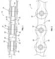
- numeral 10generally indicates a conventional roller drive chain for a bicycle or any similar chain-driven device.
- the drive chain 10generally includes outer chain links 12 and inner chain links 14 which are pivotally mounted on and connected to the outer chain links by pins 16, 18.
- the outer chain links 12are alternatingly interleaved with the inner chain links 14.
- the outer chain links 12have paired outer link plates 20 and the inner chain links have paired inner link plates 22.
- rollers 24are arranged around the pins 16, 18.
- the plates 20, 22are provided with holes 30 at their ends 32.
- the pins 16, 18typically extend through and project out of the holes 30, although no projection at all is considered to be optimal.
- the pins 16, 18are externally riveted at their ends 34, 36 during the assembly of the roller chain 10. While the pin 16 may be made of round stock, pin 18 may be made of tube stock, as in the roller chain 10 in FIG. 2 .
- a narrow middle part 38which helps to determine the positioning of the roller chain 10 extends between the two circular ends 32 of each of the outer link plates 20 and the inner link plates 22.
- the interleaving of the outer links 12 and inner links 14creates corresponding alternating outer link spaces 40 and inner links spaces 42.
- the outer link spaces 40are openings defined by the outer link plates 20 and rollers 24.
- the inner link spaces 42are openings defined by the inner link plates 22 and rollers 24.
- the inner link spaces 42are generally rectangular with the long axis of the rectangle aligned with the long axis (A) of the chain 10 (as viewed as in FIG. 1 ).
- the axial length of the inner link spaces 42is determined by the distance between the rollers 24, while the distance between the inner link plates 22 determines the transverse spacing of the inner link spaces.
- the outer link spaces 40are generally in the shape of a "cross” or in other words, a "plus.”
- the axial length of the outer link spaces 40is determined by the distance between the rollers 24, while the distance between the outer link plates 20 determines the transverse spacing of the outer link spaces.
- the transverse spacing between the outer link plates 20is greater than the spacing between the inner link plates 22.
- the rollersdictate the transverse spacing D1 of the inner link spaces 42.
- the transverse spacing D2 of the outer link spaces 40is dictated by the sum of the transverse width of the rollers 24 and the thickness of two inner link plates.
- a chainring 50is used with a conventional chain 10.
- Chainringstypically have a large plurality of teeth compared to cassettes, for example, having about 20 or more teeth.
- a crank or crank arm 48is in a typical position and attached to the chain ring 50 in a well-known manner.
- the crank side of the chainring 50is shown in FIG. 3 , which is the outboard side 54 of the chainring.
- the outboard sidealso faces away from the vehicle to which it is attached.
- the opposite of the outboard side 54 of the chainring 50is the inboard side 56.
- the inboard side 56faces toward the vehicle.
- crank arm 48typically in a downward direction, for example
- rotation of the chainring 50in a like direction (clockwise).
- Rotation of the chainring 50causes the chain 10 to be drawn over and advanced about the chainring.
- the chainring 50has a plurality of teeth 52 formed about the periphery 51 of the chainring, with the total number of the plurality of teeth consisting of an even number.
- the plurality of teeth 52include a first group of teeth 58 and a second group of teeth 60 arranged in an alternating fashion and wherein the first group of teeth is equal in number to the second group of teeth.
- the inventionprovides the first group of teeth 58, that is configured to be received by and fitted into the outer link spaces 40, and a second group of teeth 60 that is configured to be received by and fitted into the inner link spaces 42.
- the overall shape of the chainring periphery 51may be generally circular or non-circular, that is elliptical, oval, polygon, or parabolic, for example. All of the examples of chainrings provided herein are shown with a circular periphery 51.
- Each tooth of the first group of teeth 58is configured to engage with the chain 10 via an outer link space 40.
- Each tooth of the second group of teeth 60is configured to engage with the chain 10 via an inner link space 42.
- each tooth of the second group of teeth 60has a shape which in a cross sectional view is generally rectangular, particularly at or near the base or root of the tooth.
- the cross sectional viewis taken through a plane parallel to the top land 80 of the tooth and passing through the base circle position of the tooth, i.e., about halfway between the root circle and the outside circle.
- each tooth of the second group of teeth 60should closely match the configuration of each of the inner link spaces 42 ( FIG. 1 ).
- the cross section shown of each tooth of the second group of teethshows that the outboard side 54 is generally planar and the inboard side 56 is also generally planar.
- Each tooth of the second group of teeth 60may fill over about 75% of the axial distance D 1 of a corresponding space in the chain 10.
- each tooth of the second group of teeth 60may fill over about 80% of D 1 of a corresponding space in the chain 10. More preferably, each tooth of the second group of teeth 60 may fill over about 85% of D 1 of a corresponding space in the chain 10.
- each of the alternative versions of teeth 58a, 58b, 58c of the first group of teeth 58has a shape which in a cross sectional view, taken through the tooth as in FIG. 12 , has the same longitudinal length L T as that of the second group of teeth 60 ( FIG. 12 ).
- Each tooth of the first group of teeth 58may fill over about 75% of the distance D 2 of a corresponding space in the chain 10.
- each tooth of the first group of teeth 58may fill over about 80% of D 2 of a corresponding space in the chain 10. More preferably, each tooth of the first group of teeth 58 may fill over about 85% of D 2 of a corresponding space in the chain 10.
- Each tooth of the first group of teeth 58has the additional feature of an outboard or first protrusion 62 on the outboard side 54 of each alternative teeth 58a, 58b, and 58c.
- FIG. 13also demonstrates that the inboard side 56 of tooth 58a can be the same (i.e., without a protrusion) as the inboard side 56 of each tooth of the second group of teeth 60.
- the first protrusion 62is configured to fit into the corresponding part of outer link spaces 40 of chain 10 ( FIG. 1 ) and has a width W 1 .
- the protrusion 62functions to help maintain the chain 10 on the chainring 50 ( FIG. 3 ).
- the protrusion 62causes an overall width WO 2 of each of teeth 58a to be greater than the overall width WO 1 of each of teeth 60 by the extent of protrusion 62.
- FIG. 14is another embodiment of a tooth 58b of the first group of teeth 58.
- tooth 58bis similar to those of FIG. 13 , with the additional feature of an inboard or second protrusion 64 on the inboard side 56 of the tooth.
- the protrusion 64has a width W 2 that is less than the width W 1 of the protrusion 62 of tooth 58a, or alternatively, greater than W 1 .
- the protrusions 62, 64cause an overall width WO 3 of each of teeth 58b to be greater than the overall width WO 1 of each of teeth 60 by the extent of protrusions 62, 64. Furthermore, WO 3 is greater than WO 2 .
- FIG. 15is yet another embodiment of a tooth 58c of the first group of teeth 58.
- tooth 58cis similar to that of FIG. 14 , with an inboard or second protrusion 66 on the inboard side 56 of the tooth.
- the protrusion 66has a width W 1 that is equal to the width W 1 of the protrusion 62 of tooth 58a.
- the protrusions 62, 66cause an overall width WO 4 of each of teeth 58c to be greater than the overall width WO 1 of each of teeth 60 by the extent of protrusions 62, 66.
- WO 4is greater than WO 3 .
- the various configurations of the teeth 58include protrusions that are positioned along the side or sides of each tooth in a position where they effectively function to assist in positioning the chain on the chainring 50, including positions that are adjacent or at the base of each tooth or higher on each tooth 58.
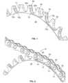
- FIG. 4 and FIG. 6is an outboard side 54 of chainring 50 and the driving direction DD.
- the first group of teeth 58is alternatingly arranged with the second group of teeth 60.
- the configuration of the second group of teeth 60may be defined, with respect to the outboard and inboard sides 54, 56 of each of the teeth 60, by forming an inner link receiving recess 72 in the chainring 50 that represents material removed from the sides of the teeth 60.
- the inner link receiving recess 72also serves to define the cross-sectional shape of each of the group of teeth 58.
- the inner link receiving recess 72defines the outboard and inboard sides 54, 56 of each tooth and extends from the front flank 68 of one of the group of teeth 58 to a rear flank 70 of an adjacent one of the group of teeth 58 in the drive direction DD.
- Each inner link receiving recess 72is configured to receive the length L P an inner link plate 22 of the chain ( FIG. 6 ).
- Each recess 72has a base surface 72a that extends in an axial direction and a wall 72b ( FIG. 7 ) that extends radially.
- the base surface 72amay describe a smoothly curving contour, and may be generally in the shape of a "U".
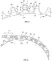
- FIG. 5is the profile of each tooth of the teeth 58, 60 in more detail.
- the inner link receiving recess 72is formed in the chainring 50 and can be seen extending along the side of each of the second group tooth 60 and extending from the load side, front or leading flank 68 of one of the group of teeth 58 to a rear flank 70 of an adjacent one of the group of teeth 58 in the drive direction DD.
- the recess 72is configured to receive the length L P ( FIG. 6 ) of an inner link plate 22.
- Each toothmay have a top land 80.
- the base surface 72amay extend to the top land 80 of each of the teeth 58.
- the front flank 68 of each toothincludes a contact zone 74, where a roller 24 ( FIG. 1 ) contacts the tooth.
- the roller 24does not contact the tip portion 76 under normal driving conditions.
- the tip portion 76may protrude forwardly from a line drawn along the contact zone 74 a distance T.
- the protruding tip portion 76functions to engage a chain link earlier than a chain lacking the tip portion and provides better guiding of the chain.
- a hook feature 78is a feature that is formed on the rear flank 70 of each of teeth 58, 60.
- the hook feature 78is positioned along the rear flank 70 and may cooperate with the tip portion 76 to provide better guiding of the chain.
- the hook feature 78may include a portion of the rear flank 70 being aligned in the radial direction R.
- each of the first group of teeth 58 and the second group of teeth 60 of the chainring 50are arranged in an alternating fashion.
- An optional feature of each of the first group of teeth 58 and second group of teeth 60is a respective outer chamfer 82a, 82b.
- Each tooth of the first group of teeth 58has an outer chamfer 82a, which may be an arcuate face formed on the outboard side 54 or shoulder of each tooth.
- Each tooth of the second group of teeth 60has an outer chamfer 82b, which may be an arcuate face formed on the outboard side 54 or shoulder of each tooth.
- the outer chamfer of 82b of each tooth 60may have an extent C, that is greater relative to the extent C 2 of the outer chamfer 82a of each tooth 58.
- the chainring 50includes chain 10 positioned and engaged thereon.
- Outer chain links 12are positioned on the first group of teeth 58.
- Inner chain links 14are positioned on the second group of teeth 60.
- FIGS. 10 and 11respectively is a front view of the chainring 50 without a chain 10 and with a chain.
- An optional feature of all of the teeth 58, 60 of the chainring 50is an offset OS of the center of the tooth tip or top land 80 from the center line CL in a direction toward the inboard side 56 of the chainring. This offset feature provides better guiding of the chain to one side of the chainring.
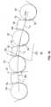
- a chainring 50includes a number of teeth 58, 60.
- Link 1 of a chain engaged on the chainring 50is represented by line L 1
- link 2 and link 3are represented by lines L 2 , L 3 respectively.
- the line of each of L 1-3is drawn between the centers of the axis of each of the chain rollers 24.
- the hook feature 78is shown on the rear flank 70 of each of teeth 58, 60.
- the hook feature 78is positioned along the rear flank 70 and may cooperate with the tip portion 76 of the front flank 68 to provide better guiding of the chain.
- the hook feature 78may include a portion of the rear flank 70 being aligned in the radial direction R.
- the hook feature 78has a radially outermost extent 78a where the hook feature and the link centerlines L 1-3 intersect. Alternately, the outermost extent 78a may be higher than the centerlines L 1-3 , providing more room for the roller to engage the teeth in the driving direction.
- the curved line 90is the path of the roller 24 when it disengages the tooth.
- the chain 10is installed with each of the outer chain links 12 on one of the first group of teeth 58 and each of the inner chain links 14 on one of the second group of teeth 60.
- the chainring 50is rotated by the crank 48, the chain 10 is drawn about the chainring, and the outer chain links 12 and the inner chain links 14 are sequentially engaged with respective first and second ones of the groups of teeth 58, 60.
- the various features of the chainring 50function to guide and maintain the chain 10 thereon.
Landscapes
- Engineering & Computer Science (AREA)
- Mechanical Engineering (AREA)
- Chemical & Material Sciences (AREA)
- Combustion & Propulsion (AREA)
- Transportation (AREA)
- General Engineering & Computer Science (AREA)
- Devices For Conveying Motion By Means Of Endless Flexible Members (AREA)
- Gears, Cams (AREA)
- Automatic Cycles, And Cycles In General (AREA)
Description
- This invention relates to chainrings, and more particularly, to a solitary chainring for use with a conventional chain in a bicycle drivetrain system including a bicycle crank according to claim 1.
- Bicycles and other chain-driven vehicles typically employ one or more chainrings and a set of rear hub mounted sprockets connected by a chain. Various mechanisms are used to maintain the chain on the chainring and sprockets. These mechanisms include chain guards, chain tensioners, chain catchers, derailleur configurations and so on.
- While riding a vehicle with a chain driven drivetrain, management of the chain and chainring engagement is particularly important to safe and effective propulsion of the bicycle. Keeping the chain engaged with the chainring can be difficult, which is especially true of geared bicycles which can experience severe changes in chain tension, and energetic motion of the chain, especially from riding over rough terrain.
- Moreover, the chainring in any bicycle can potentially touch the chain stay of the bicycle frame when the crank is in a position where high loads are applied by the rider, causing an elastic deformation of the bicycle frame and the crankset. This can lead to damage to the frame and chainring and cause other problems.
- The invention provides an enhanced drive chain management, especially for a bicycle that can successfully and reliably be ridden over rough and challenging terrain.
- Document
EP 0 034 445 A2 describes a bicycle chainring including a number of regular teeth and groups of at least two consecutive teeth having a reduced width or a twisted shape in order to provide better shifting characteristics. - Document
WO 03/095867 A1 - Document
JP S56 42489 U - Document
US 3,956,943 describes a sprocket wheel having a first group of teeth and a second group of teeth arranged alternatingly wherein the first teeth are arranged axially offset of the second teeth. WO 93/07044 A1 - The invention provides a chainring having the features of claim 1. In particular the invention provides in one aspect, a solitary chainring of a bicycle front crankset for engaging a drive chain. The solitary chainring, wherein solitary means only one, includes a plurality of teeth formed about a periphery of the chainring, the plurality of teeth consisting of an even number. The plurality of teeth includes a first group of teeth and a second group of teeth arranged alternatingly between the first group of teeth. The first group of teeth and the second group of teeth are equal in number. Each tooth of the first and second group of teeth includes an outboard side and an inboard side opposite the outboard side. Each tooth of the first group of teeth includes at least a first protrusion on the outboard side thereof and each tooth of the second group of teeth is free of protrusions.
- The chainring may further comprise a second protrusion on the inboard side of each tooth of the first group of teeth.
- The chainring may further provide that the first protrusion has a first width and the second protrusion has a second width, wherein the first width is equal to the second width.
- The chainring may further provide that the first width is greater than the second width. The chainring specified above according to the invention may further provide that the first group of teeth each have a cross-shaped cross section adjacent a base thereof.
- The chainring specified above according to the invention may further provide that the second group of teeth each have a rectangular-shaped cross section adjacent a base thereof.
- The chainring specified above according to the invention may further provide that each tooth of the first group of teeth and the second group teeth include a front flank, and wherein the front flank includes a protruding tip portion configured to guide the chain.
- According to the invention, each tooth of the first group of teeth and the second group teeth include a rear flank, and wherein the rear flank includes a hook feature configured to guide the chain.
- The chainring specified above according to the invention may further provide that each tooth of the first group of teeth and the second group teeth include a front flank and a rear flank, wherein the front flank of each tooth includes a protruding tip portion.
- According to the invention, the hook portion includes a generally radially-oriented portion.
- The chainring specified above according to the invention may further provide that the protruding tip portion and an adjacent tooth hook portion cooperate to guide the chain.
- The chainring may further provide that each tooth of the first group of teeth includes a radially outer chamfer having a first extent along the outboard side of each tooth.
- The chainring may further provide that each tooth of the second group of teeth includes a radially outer chamfer having a second extent along the outboard side of each tooth.
- The chainring may further provide that each tooth of the first group of teeth includes an outer chamfer having a first extent and each tooth of the second group of teeth includes an outer chamfer having a second extent and the first extent is lesser than the second extent.
- The chainring specified above according to the invention may further provide that each of the inboard and outboard sides of each tooth of the second group of teeth define a recess formed in the chainring.
- The chainring may further provide that each recess is defined by an axially-extending base surface and a radially-extending wall.
- The chainring may further provide that each recess extends from a front flank of a first tooth of the first group of teeth to a rear flank of a second tooth of the first group of teeth, wherein the first tooth and the second tooth are adjacent ones of the first group of teeth in a drive direction.
- The chainring may further comprise a first protrusion on the outboard side and a second protrusion on the inboard side of each tooth of the first group of teeth, the first and second protrusions defined at least in part by the recess.
- The chainring may further provide that the first protrusion has a first width and the second protrusion has a second width, wherein the first width is equal to the second width.
- The first width may be greater than the second width.
- The chainring specified above according to the invention may further provide that the first group of teeth each have a cross-shaped cross section adjacent a base thereof defined by the recess.
- The chainring specified above according to the invention may further provide that the second group of teeth each have a rectangular-shaped cross section adjacent a base thereof defined by the recess.
- The invention further contemplates a bicycle crankset, comprising:
- a bicycle crank arm; and
- a solitary chainring as defined above attached to the bicycle crank arm and engageable with a drive chain.
- These and other features and advantages of the present invention will be more fully understood from the following description of one or more embodiments of the invention, taken together with the accompanying drawings.
- In the drawings:
- FIG. 1
- is a top view of a conventional drive chain;
- FIG. 2
- is a side view of the conventional drive chain of
FIG. 1 ; - FIG. 3
- is an isometric view of a combined drive chain and chainring according to the invention engaged by a drivetrain;
- FIG. 4
- is a side view of the chainring according to the invention;
- FIG. 5
- is a close up of the chainring of
FIG. 4 ; - FIG. 6
- is a side view of a combined drive chain and chainring according to the invention engaged by a drive chain with the outer link plates removed;
- FIG. 7
- is a front isometric view of the chainring according to the invention;
- FIG. 8
- is a front isometric view of the chainring according to
FIG. 7 , engaged by a drive chain; - FIG. 9
- is a rear isometric view of the chainring according to
FIG. 7 , engaged by a drive chain; - FIG. 10
- is a front view of the chainring according to the invention;
- FIG. 11
- is a front view of the chainring according to the invention engaged by a drive chain;
- FIG. 12
- is a cross sectional view through line B-B of
FIG. 5 of one type of gear tooth according to one group of teeth; - FIGS. 13-15
- are cross sectional views through line A-A of
FIG. 5 of alternative types of gear teeth that are different than the tooth ofFIG. 12 and according to another group of teeth; and - FIG. 16
- is a partial side view of the chainring according to the invention with rollers of a chain engaged with the teeth of the chainring.
- Preferred embodiments of the invention will herein be described with reference to the drawings. It will be understood that the drawings and descriptions set out herein are provided for illustration only and do not limit the invention as defined by the claims appended hereto and any and all their equivalents. For example, the terms "first" and "second" or "left" and "right" are used for the sake of clarity and not as terms of limitation.
- Referring to
FIGS. 1 and 2 of the drawings, numeral 10 generally indicates a conventional roller drive chain for a bicycle or any similar chain-driven device. Thedrive chain 10 generally includes outer chain links 12 and inner chain links 14 which are pivotally mounted on and connected to the outer chain links bypins - The outer chain links 12 have paired
outer link plates 20 and the inner chain links have pairedinner link plates 22. Typically,rollers 24 are arranged around thepins plates holes 30 at their ends 32. Thepins holes 30, although no projection at all is considered to be optimal. Thepins ends roller chain 10. While thepin 16 may be made of round stock,pin 18 may be made of tube stock, as in theroller chain 10 inFIG. 2 . A narrowmiddle part 38, which helps to determine the positioning of theroller chain 10 extends between the two circular ends 32 of each of theouter link plates 20 and theinner link plates 22. - As seen best in
FIG. 1 , and as viewed from above (or below) the chain, the interleaving of theouter links 12 andinner links 14 creates corresponding alternatingouter link spaces 40 andinner links spaces 42. Generally, theouter link spaces 40 are openings defined by theouter link plates 20 androllers 24. Generally, theinner link spaces 42 are openings defined by theinner link plates 22 androllers 24. - The
inner link spaces 42 are generally rectangular with the long axis of the rectangle aligned with the long axis (A) of the chain 10 (as viewed as inFIG. 1 ). The axial length of theinner link spaces 42 is determined by the distance between therollers 24, while the distance between theinner link plates 22 determines the transverse spacing of the inner link spaces. - As seen in
FIG. 1 , theouter link spaces 40 are generally in the shape of a "cross" or in other words, a "plus." The axial length of theouter link spaces 40 is determined by the distance between therollers 24, while the distance between theouter link plates 20 determines the transverse spacing of the outer link spaces. - It can be seen that the transverse spacing between the
outer link plates 20 is greater than the spacing between theinner link plates 22. Thus, because the transverse width of therollers 24 determines the spacing of theinner link plates 22, the rollers dictate the transverse spacing D1 of theinner link spaces 42. Similarly, since theouter link plates 20 are positioned on the pins 16 (or 18) on the outboard sides of theinner link plates 22, the transverse spacing D2 of theouter link spaces 40 is dictated by the sum of the transverse width of therollers 24 and the thickness of two inner link plates. - Referring to
FIG. 3 , achainring 50 according to the invention is used with aconventional chain 10. Chainrings typically have a large plurality of teeth compared to cassettes, for example, having about 20 or more teeth. A crank or crankarm 48 is in a typical position and attached to thechain ring 50 in a well-known manner. The crank side of thechainring 50 is shown inFIG. 3 , which is theoutboard side 54 of the chainring. The outboard side also faces away from the vehicle to which it is attached. The opposite of theoutboard side 54 of thechainring 50 is theinboard side 56. Theinboard side 56 faces toward the vehicle. - Generally, force applied to the crank arm 48 (typically in a downward direction, for example) causes rotation of the
chainring 50 in a like direction (clockwise). Rotation of thechainring 50 causes thechain 10 to be drawn over and advanced about the chainring. - The
chainring 50 has a plurality ofteeth 52 formed about theperiphery 51 of the chainring, with the total number of the plurality of teeth consisting of an even number. The plurality ofteeth 52 include a first group ofteeth 58 and a second group ofteeth 60 arranged in an alternating fashion and wherein the first group of teeth is equal in number to the second group of teeth. In a most general form, the invention provides the first group ofteeth 58, that is configured to be received by and fitted into theouter link spaces 40, and a second group ofteeth 60 that is configured to be received by and fitted into theinner link spaces 42. - The overall shape of the
chainring periphery 51 may be generally circular or non-circular, that is elliptical, oval, polygon, or parabolic, for example. All of the examples of chainrings provided herein are shown with acircular periphery 51. - Each tooth of the first group of
teeth 58 is configured to engage with thechain 10 via anouter link space 40. Each tooth of the second group ofteeth 60 is configured to engage with thechain 10 via aninner link space 42. - Turning to
FIG. 12 , each tooth of the second group ofteeth 60 has a shape which in a cross sectional view is generally rectangular, particularly at or near the base or root of the tooth. The cross sectional view is taken through a plane parallel to thetop land 80 of the tooth and passing through the base circle position of the tooth, i.e., about halfway between the root circle and the outside circle. - The rectangular cross section and overall width WO, of each tooth of the second group of
teeth 60 should closely match the configuration of each of the inner link spaces 42 (FIG. 1 ). The cross section shown of each tooth of the second group of teeth shows that theoutboard side 54 is generally planar and theinboard side 56 is also generally planar. Each tooth of the second group ofteeth 60 may fill over about 75% of the axial distance D1 of a corresponding space in thechain 10. Preferably, each tooth of the second group ofteeth 60 may fill over about 80% of D1 of a corresponding space in thechain 10. More preferably, each tooth of the second group ofteeth 60 may fill over about 85% of D1 of a corresponding space in thechain 10. - Turning to
FIG. 13-15 , each of the alternative versions ofteeth FIG. 3 ) has a shape which in a cross sectional view, taken through the tooth as inFIG. 12 , has the same longitudinal length LT as that of the second group of teeth 60 (FIG. 12 ). Each tooth of the first group ofteeth 58 may fill over about 75% of the distance D2 of a corresponding space in thechain 10. Preferably, each tooth of the first group ofteeth 58 may fill over about 80% of D2 of a corresponding space in thechain 10. More preferably, each tooth of the first group ofteeth 58 may fill over about 85% of D2 of a corresponding space in thechain 10. - Each tooth of the first group of
teeth 58 has the additional feature of an outboard orfirst protrusion 62 on theoutboard side 54 of eachalternative teeth FIG. 13 also demonstrates that theinboard side 56 oftooth 58a can be the same (i.e., without a protrusion) as theinboard side 56 of each tooth of the second group ofteeth 60. Thefirst protrusion 62 is configured to fit into the corresponding part ofouter link spaces 40 of chain 10 (FIG. 1 ) and has a width W1. Theprotrusion 62 functions to help maintain thechain 10 on the chainring 50 (FIG. 3 ). Theprotrusion 62 causes an overall width WO2 of each ofteeth 58a to be greater than the overall width WO1 of each ofteeth 60 by the extent ofprotrusion 62. FIG. 14 is another embodiment of atooth 58b of the first group ofteeth 58. In particular,tooth 58b is similar to those ofFIG. 13 , with the additional feature of an inboard orsecond protrusion 64 on theinboard side 56 of the tooth. Theprotrusion 64 has a width W2 that is less than the width W1 of theprotrusion 62 oftooth 58a, or alternatively, greater than W1. Theprotrusions teeth 58b to be greater than the overall width WO1 of each ofteeth 60 by the extent ofprotrusions FIG. 15 is yet another embodiment of atooth 58c of the first group ofteeth 58. In particular,tooth 58c is similar to that ofFIG. 14 , with an inboard orsecond protrusion 66 on theinboard side 56 of the tooth. Theprotrusion 66 has a width W1 that is equal to the width W1 of theprotrusion 62 oftooth 58a. Theprotrusions teeth 58c to be greater than the overall width WO1 of each ofteeth 60 by the extent ofprotrusions - It will be understood that the various configurations of the
teeth 58 include protrusions that are positioned along the side or sides of each tooth in a position where they effectively function to assist in positioning the chain on thechainring 50, including positions that are adjacent or at the base of each tooth or higher on eachtooth 58. FIG. 4 andFIG. 6 is anoutboard side 54 ofchainring 50 and the driving direction DD. The first group ofteeth 58 is alternatingly arranged with the second group ofteeth 60.- The configuration of the second group of
teeth 60 may be defined, with respect to the outboard andinboard sides teeth 60, by forming an innerlink receiving recess 72 in thechainring 50 that represents material removed from the sides of theteeth 60. The innerlink receiving recess 72 also serves to define the cross-sectional shape of each of the group ofteeth 58. The innerlink receiving recess 72 defines the outboard andinboard sides front flank 68 of one of the group ofteeth 58 to arear flank 70 of an adjacent one of the group ofteeth 58 in the drive direction DD. Each innerlink receiving recess 72 is configured to receive the length LP aninner link plate 22 of the chain (FIG. 6 ). Eachrecess 72 has abase surface 72a that extends in an axial direction and awall 72b (FIG. 7 ) that extends radially. Thebase surface 72a may describe a smoothly curving contour, and may be generally in the shape of a "U". FIG. 5 is the profile of each tooth of theteeth link receiving recess 72 is formed in thechainring 50 and can be seen extending along the side of each of thesecond group tooth 60 and extending from the load side, front or leadingflank 68 of one of the group ofteeth 58 to arear flank 70 of an adjacent one of the group ofteeth 58 in the drive direction DD. Therecess 72 is configured to receive the length LP (FIG. 6 ) of aninner link plate 22. Each tooth may have atop land 80. Thebase surface 72a may extend to thetop land 80 of each of theteeth 58. Thefront flank 68 of each tooth includes acontact zone 74, where a roller 24 (FIG. 1 ) contacts the tooth.- Above the
contact zone 74 is anoptional tip portion 76. Theroller 24 does not contact thetip portion 76 under normal driving conditions. Thetip portion 76 may protrude forwardly from a line drawn along the contact zone 74 a distance T. The protrudingtip portion 76 functions to engage a chain link earlier than a chain lacking the tip portion and provides better guiding of the chain. - A
hook feature 78 is a feature that is formed on therear flank 70 of each ofteeth hook feature 78 is positioned along therear flank 70 and may cooperate with thetip portion 76 to provide better guiding of the chain. Thehook feature 78 may include a portion of therear flank 70 being aligned in the radial direction R. - Turning to
FIG. 7 the first group ofteeth 58 and the second group ofteeth 60 of thechainring 50 are arranged in an alternating fashion. An optional feature of each of the first group ofteeth 58 and second group ofteeth 60 is a respectiveouter chamfer teeth 58 has anouter chamfer 82a, which may be an arcuate face formed on theoutboard side 54 or shoulder of each tooth. Each tooth of the second group ofteeth 60 has anouter chamfer 82b, which may be an arcuate face formed on theoutboard side 54 or shoulder of each tooth. The outer chamfer of 82b of eachtooth 60 may have an extent C, that is greater relative to the extent C2 of theouter chamfer 82a of eachtooth 58. - Turning to
FIGS. 8 and9 thechainring 50 includeschain 10 positioned and engaged thereon. Outer chain links 12 are positioned on the first group ofteeth 58. Inner chain links 14 are positioned on the second group ofteeth 60. FIGS. 10 and 11 respectively is a front view of thechainring 50 without achain 10 and with a chain. An optional feature of all of theteeth chainring 50 is an offset OS of the center of the tooth tip ortop land 80 from the center line CL in a direction toward theinboard side 56 of the chainring. This offset feature provides better guiding of the chain to one side of the chainring.- Turning to
FIG. 16 , achainring 50 includes a number ofteeth chainring 50 is represented by line L1, and link 2 and link 3 are represented by lines L2, L3 respectively. The line of each of L1-3 is drawn between the centers of the axis of each of thechain rollers 24. - The
hook feature 78 is shown on therear flank 70 of each ofteeth hook feature 78 is positioned along therear flank 70 and may cooperate with thetip portion 76 of thefront flank 68 to provide better guiding of the chain. Thehook feature 78 may include a portion of therear flank 70 being aligned in the radial direction R. Thehook feature 78 has a radiallyoutermost extent 78a where the hook feature and the link centerlines L1-3 intersect. Alternately, theoutermost extent 78a may be higher than the centerlines L1-3, providing more room for the roller to engage the teeth in the driving direction. Thecurved line 90 is the path of theroller 24 when it disengages the tooth. - In use, the
chain 10 is installed with each of the outer chain links 12 on one of the first group ofteeth 58 and each of the inner chain links 14 on one of the second group ofteeth 60. As thechainring 50 is rotated by thecrank 48, thechain 10 is drawn about the chainring, and the outer chain links 12 and the inner chain links 14 are sequentially engaged with respective first and second ones of the groups ofteeth chainring 50 function to guide and maintain thechain 10 thereon.
Claims (9)
- A bicycle solitary chainring (50) of a bicycle front crank set for engagement with a drive chain (10), comprising:a plurality of teeth (52) extending from a periphery of the chainring (50), wherein the plurality of teeth (52) is formed about the periphery of the chainring (50); the plurality of teeth (52) consists of an even number;the plurality of teeth (52) including a first group of teeth (58) and a second group of teeth (60), each tooth of the first group of teeth (58) is wider than each tooth of the second group of teeth (60) in the axial direction of the chain ring (50) wherein each tooth of the plurality of teeth (52) includes an outboard side (54) and an inboard side (56) opposite the outboard side (54) and each tooth of the first group of teeth (58) includes at least a first protrusion (62) on the outboard side (54) and each tooth of the second group of teeth (60) is free of protrusions; wherein the first group of teeth (58) and the second group of teeth (60) are equal in number;wherein the teeth of the second group of teeth (60) are arranged alternatingly and adjacently between teeth of the first group of teeth, such that a single tooth of the first group of teeth (58) is arranged between two successive teeth of the second group of teeth (60); andwherein each tooth of the first and second group of teeth (60) include a front flank (68) and a rear flank (70);characterized in thatthe front flanks (68) and rear flanks (70) of the same tooth of the first group of teeth (58) have differing shapes when viewed in an axial direction, wherein the rear flank (70) of each tooth of the first group of teeth (58) includes a hook feature (78) configured for guiding the drive chain (10), wherein the shape of the rear flank (70) of each tooth of the first group of teeth (58) is differing by the hook feature (78) from the shape of the front flank (68) of the same tooth when viewed in an axial direction, andwherein the front flanks (68) and rear flanks (70) of the same tooth of the second group of teeth have differing shapes when viewed in an axial direction, wherein the rear flank (70) of each tooth of the second group of teeth (60) includes a hook feature (78) configured for guiding the drive chain (10), wherein the shape of the rear flank (70) of each tooth of the second group of teeth (60) is differing by the hook feature (78) from the shape of the front flank (68) of the same tooth when viewed in an axial direction, wherein the hook feature (78) includes a portion of the rear flank (70) being aligned in the radial direction (R) of the chainring (50), wherein the rear flank (70) between a top land (80) and the portion being aligned in the radial direction (R) of the chainring exceeds away from the radial direction (R) in direction to the front flank (68) of the same tooth.
- The bicycle solitary chainring (50) of claim 1, wherein each tooth of the first group of teeth (58) includes a second protrusion (64) on the inboard side (56), wherein the first protrusion (62) has a first width, and the second protrusion (64) has a second width; and
wherein the first and the second protrusion (64) widths are equal, or wherein the first width is greater than the second width. - The bicycle solitary chainring (50) of one the claims 1 or 2, wherein the front flank (68) of each tooth includes a contact zone (74) configured to be contacted by a roller of the chain.
- The bicycle solitary chainring (50) of claim 3, wherein a protruding tip portion (76) and an adjacent tooth hook feature (78) cooperate to guide the drive chain (10).
- The bicycle solitary chainring (50) of claim 1, wherein a plane (CL) bisects the chainring (50) into the outboard side (54) and the inboard side (56) opposite the outboard side (54); and
wherein the center of the tooth tips (80) of the first and second groups of teeth are offset from the plane in a direction toward the inboard side (56) of the chainring (50), wherein in particular the center of the top land of the first and second groups of teeth (58, 60) is offset from the plane in said direction toward the inboard side (56) of the chainring (50). - The bicycle solitary chainring (50) of claim 1, adapted for engagement with a roller drive chain (10), the roller drive chain (10) having alternating outer and inner chain links defining outer and inner link spaces (40, 42), respectively, wherein each tooth of the first group of teeth (58) is sized and shaped such that it is adapted to fit within one of the outer link spaces (40) and each tooth of the second group of teeth (60) is sized and shaped such that it is adapted to fit within one of the inner link spaces (42).
- The bicycle solitary chainring (50) of claim 1, adapted for engagement with a roller drive chain (10), the roller drive chain (10) having alternating outer and inner chain links (20, 22) defining outer and inner link spaces (42), respectively, wherein the first group of teeth (58) has a cross-shaped cross section adjacent a base thereof defined by a recess;each tooth of the first group of teeth (58) is sized and shaped such that it is adapted to fit within one of the outer link spaces (40) and each tooth of the second group of teeth (60) is sized and shaped to fit within one of the inner link spaces (42); andwherein said chainring (50) is configured and adapted to guide and maintain the drive chain (10) thereon.
- The bicycle solitary chainring (50) of claim 1, wherein the second group of teeth (60) having a rectangular-shaped cross-section adjacent a base thereof defined by a recess.
- Bicycle crankset comprising:a crank arm (48), anda bicycle solitary chainring (50) according to one of the claims 1 to 8 attached to the crank arm (48).
Applications Claiming Priority (2)
| Application Number | Priority Date | Filing Date | Title |
|---|---|---|---|
| US13/311,735US9182027B2 (en) | 2011-12-06 | 2011-12-06 | Chainring |
| EP12008132.8AEP2602176B1 (en) | 2011-12-06 | 2012-12-05 | Chainring |
Related Parent Applications (2)
| Application Number | Title | Priority Date | Filing Date |
|---|---|---|---|
| EP12008132.8ADivision-IntoEP2602176B1 (en) | 2011-12-06 | 2012-12-05 | Chainring |
| EP12008132.8ADivisionEP2602176B1 (en) | 2011-12-06 | 2012-12-05 | Chainring |
Publications (2)
| Publication Number | Publication Date |
|---|---|
| EP3072799A1 EP3072799A1 (en) | 2016-09-28 |
| EP3072799B1true EP3072799B1 (en) | 2023-11-08 |
Family
ID=47504563
Family Applications (7)
| Application Number | Title | Priority Date | Filing Date |
|---|---|---|---|
| EP16000947.8AActiveEP3072801B1 (en) | 2011-12-06 | 2012-12-05 | Chainring |
| EP16000933.8AActiveEP3072799B1 (en) | 2011-12-06 | 2012-12-05 | Chainring |
| EP16000934.6AActiveEP3072800B1 (en) | 2011-12-06 | 2012-12-05 | Chainring |
| EP16000949.4AWithdrawnEP3072803A1 (en) | 2011-12-06 | 2012-12-05 | Chainring |
| EP16000948.6AActiveEP3072802B1 (en) | 2011-12-06 | 2012-12-05 | Chainring |
| EP12008132.8AActiveEP2602176B1 (en) | 2011-12-06 | 2012-12-05 | Chainring |
| EP16000950.2AActiveEP3075644B1 (en) | 2011-12-06 | 2012-12-05 | Chainring |
Family Applications Before (1)
| Application Number | Title | Priority Date | Filing Date |
|---|---|---|---|
| EP16000947.8AActiveEP3072801B1 (en) | 2011-12-06 | 2012-12-05 | Chainring |
Family Applications After (5)
| Application Number | Title | Priority Date | Filing Date |
|---|---|---|---|
| EP16000934.6AActiveEP3072800B1 (en) | 2011-12-06 | 2012-12-05 | Chainring |
| EP16000949.4AWithdrawnEP3072803A1 (en) | 2011-12-06 | 2012-12-05 | Chainring |
| EP16000948.6AActiveEP3072802B1 (en) | 2011-12-06 | 2012-12-05 | Chainring |
| EP12008132.8AActiveEP2602176B1 (en) | 2011-12-06 | 2012-12-05 | Chainring |
| EP16000950.2AActiveEP3075644B1 (en) | 2011-12-06 | 2012-12-05 | Chainring |
Country Status (7)
| Country | Link |
|---|---|
| US (9) | US9182027B2 (en) |
| EP (7) | EP3072801B1 (en) |
| CN (7) | CN105905228B (en) |
| DE (10) | DE102012025875B3 (en) |
| ES (6) | ES2666831T3 (en) |
| PL (6) | PL3075644T3 (en) |
| TW (19) | TWI744726B (en) |
Families Citing this family (97)
| Publication number | Priority date | Publication date | Assignee | Title |
|---|---|---|---|---|
| US8820192B2 (en) | 2009-04-29 | 2014-09-02 | Race Face Prerformance Products Inc. | Bicycle crank arm and insert therefore |
| US20130116074A1 (en)* | 2011-11-08 | 2013-05-09 | Chang Hui Lin | Sprocket wheel for bicycle |
| US9182027B2 (en) | 2011-12-06 | 2015-11-10 | Sram, Llc | Chainring |
| US9062758B2 (en)* | 2011-12-06 | 2015-06-23 | Sram, Llc | Chainring |
| US9701364B2 (en) | 2013-05-17 | 2017-07-11 | Shimano Inc. | Bicycle sprocket and bicycle crank assembly |
| DE102014007274A1 (en)* | 2013-05-17 | 2014-11-20 | Shimano Inc. | Bicycle sprocket and bike crank assembly |
| DE102013009492B4 (en) | 2013-06-05 | 2023-10-19 | Sram Deutschland Gmbh | Chain ring |
| US9150277B2 (en) | 2014-01-07 | 2015-10-06 | Shimano Inc. | Bicycle crank assembly |
| US9086138B1 (en)* | 2014-01-14 | 2015-07-21 | Shimano Inc. | Bicycle sprocket |
| US10000256B2 (en)* | 2014-01-23 | 2018-06-19 | Shimano Inc. | Bicycle sprocket |
| DE102015000912B4 (en) | 2014-01-23 | 2024-02-22 | Shimano Inc. | Bicycle chainring |
| US9581230B2 (en) | 2014-02-10 | 2017-02-28 | Wolf Tooth Components, LLC | Sprocket |
| US9394986B2 (en)* | 2014-02-10 | 2016-07-19 | Wolf Tooth Components, LLC | Sprocket |
| US9394987B2 (en)* | 2014-02-10 | 2016-07-19 | Wolf Tooth Components, LLC | Sprocket |
| US9581229B2 (en)* | 2014-02-10 | 2017-02-28 | Wolf Tooth Components, LLC | Sprocket |
| US9669899B2 (en)* | 2014-02-27 | 2017-06-06 | Eko Sport, Inc. | Alternating tooth chain ring |
| US9404565B2 (en)* | 2014-04-08 | 2016-08-02 | Wolf Tooth Components, LLC | Sprocket |
| US9625027B2 (en)* | 2014-04-08 | 2017-04-18 | Wolf Tooth Components, LLC | Sprocket |
| US9581231B2 (en)* | 2014-04-08 | 2017-02-28 | Wolf Tooth Components, LLC | Sprocket |
| US9409624B2 (en) | 2014-04-11 | 2016-08-09 | Shimano Inc. | Bicycle sprocket |
| US9964196B2 (en)* | 2014-05-20 | 2018-05-08 | Shimano Inc. | Bicycle sprocket |
| US20170191558A1 (en)* | 2014-05-29 | 2017-07-06 | Miranda & Irmaco, Lda. | Drivetrain system and use thereof |
| US9334014B2 (en)* | 2014-09-01 | 2016-05-10 | Shimano Inc. | Bicycle sprocket and bicycle sprocket assembly |
| US9463844B2 (en)* | 2014-09-01 | 2016-10-11 | Shimano Inc. | Bicycle sprocket and bicycle sprocket assembly |
| AU358118S (en)* | 2014-09-25 | 2014-10-13 | Calcino Corp Pty Ltd | A sprocket |
| DE102015219522B4 (en)* | 2014-10-14 | 2025-07-24 | Sram Deutschland Gmbh | Multiple sprocket arrangement for a rear wheel hub |
| USD750998S1 (en)* | 2014-12-19 | 2016-03-08 | John Wang | Sprocket |
| US9599208B2 (en)* | 2015-02-12 | 2017-03-21 | Sram, Llc | Chainrings and crank assemblies |
| US9631714B2 (en) | 2015-03-24 | 2017-04-25 | Shimano Inc. | Bicycle sprocket and bicycle crank assembly |
| USD774987S1 (en)* | 2015-04-01 | 2016-12-27 | Tien Hsin Industries Co., Ltd. | Bicycle sprocket |
| EP3283792B1 (en) | 2015-04-13 | 2024-12-25 | Eko Sport, Inc. | Chain ring with teeth oppositely laterally engaging a drive chain |
| US9540070B2 (en)* | 2015-05-27 | 2017-01-10 | Shimano Inc. | Bicycle sprocket and bicycle crank assembly |
| US10703441B2 (en) | 2015-07-03 | 2020-07-07 | Sram Deutschland Gmbh | Drive arrangement for a bicycle |
| DE102015017347B3 (en) | 2015-07-03 | 2023-09-21 | Sram Deutschland Gmbh | Single sprocket for a bicycle front crank assembly |
| DE102015008662A1 (en) | 2015-07-03 | 2017-01-05 | Sram Deutschland Gmbh | Single sprocket for a bicycle forward crank assembly |
| US9926038B2 (en) | 2015-07-28 | 2018-03-27 | Shimano Inc. | Bicycle sprocket, bicycle rear sprocket, and bicycle multiple sprocket assembly |
| JP2017071380A (en)* | 2015-10-09 | 2017-04-13 | 株式会社シマノ | Sprocket for bicycle and sprocket assembly for bicycle |
| US20170101159A1 (en)* | 2015-10-09 | 2017-04-13 | Shimano Inc. | Bicycle sprocket and bicycle sprocket assembly |
| DE102015016767A1 (en) | 2015-12-23 | 2017-06-29 | Sram Deutschland Gmbh | Drive arrangement of a bicycle with a multiple sprocket arrangement |
| US10549816B2 (en) | 2016-02-26 | 2020-02-04 | Shimano Inc. | Bicycle sprocket and bicycle sprocket assembly |
| EP3239035A1 (en) | 2016-04-11 | 2017-11-01 | Fox Factory, Inc. | Bicycle front sprocket |
| EP3251938A1 (en) | 2016-06-03 | 2017-12-06 | ZUMA Innovation, S.L. | Chain-rings set for a power transmission system provided with segmented chain-rings in different planes |
| EP3251937A1 (en) | 2016-06-03 | 2017-12-06 | ZUMA Innovation, S.L. | Chain-rings set for a bicycle power transmission system provided with segmented chain-ring |
| EP3251940B1 (en) | 2016-06-03 | 2018-12-19 | ZUMA Innovation, S.L. | Chain-ring set for a power transmission system |
| US10247291B2 (en)* | 2016-06-24 | 2019-04-02 | Shimano Inc. | Bicycle sprocket and bicycle sprocket assembly |
| US10359106B2 (en)* | 2016-06-24 | 2019-07-23 | Shimano Inc. | Bicycle sprocket and bicycle sprocket assembly |
| US9885409B1 (en) | 2016-09-12 | 2018-02-06 | Shimano Inc. | Bicycle sprocket and bicycle rear sprocket assembly |
| US10138991B2 (en)* | 2016-09-14 | 2018-11-27 | Shimano Inc. | Bicycle sprocket |
| US9915336B1 (en)* | 2016-09-14 | 2018-03-13 | Shimano Inc. | Bicycle sprocket assembly |
| US10377445B2 (en)* | 2016-09-20 | 2019-08-13 | Shimano Inc. | Bicycle front sprocket assembly |
| US20170016524A1 (en)* | 2016-09-28 | 2017-01-19 | Chao-Yuan Cheng | Bicycle sprocket wheel |
| US10507888B2 (en)* | 2016-11-10 | 2019-12-17 | Shimano Inc. | Bicycle crank assembly and bicycle sprocket assembly |
| US10358186B2 (en)* | 2016-12-16 | 2019-07-23 | Shimano Inc. | Bicycle sprocket and bicycle sprocket assembly |
| DE102016015433A1 (en)* | 2016-12-23 | 2018-06-28 | Sram Deutschland Gmbh | Multiple sprocket assembly and bicycle drive with such a multiple sprocket arrangement |
| US10577050B2 (en)* | 2016-12-26 | 2020-03-03 | Shimano Inc. | Bicycle sprocket |
| US10295041B2 (en)* | 2016-12-26 | 2019-05-21 | Shimano Inc. | Bicycle sprocket and bicycle sprocket assembly |
| TW201825811A (en) | 2017-01-03 | 2018-07-16 | 榮輪科技股份有限公司 | Manufacturing method of single chain wheel forming an intermediate tooth with a thickness for allowing an inner width of an inner panel of a chain to be smoothly fitted therein |
| US10378637B2 (en)* | 2017-01-19 | 2019-08-13 | Shimano Inc. | Bicycle sprocket |
| CN108343708B (en)* | 2017-01-23 | 2024-11-05 | 超汇桂盟传动(苏州)有限公司 | Chain and inner link |
| US10625821B2 (en)* | 2017-03-17 | 2020-04-21 | Shimano Inc. | Bicycle sprocket and bicycle sprocket assembly |
| JP2018179046A (en)* | 2017-04-05 | 2018-11-15 | 株式会社シマノ | Sprocket for bicycle and sprocket assembly for bicycle |
| US10309515B2 (en)* | 2017-04-17 | 2019-06-04 | Shimano Inc. | Bicycle rear sprocket |
| US10703439B2 (en) | 2017-04-20 | 2020-07-07 | Shimano Inc. | Bicycle sprocket |
| US11014628B2 (en) | 2017-04-28 | 2021-05-25 | Fox Factory, Inc. | Cinch direct mount 2X ring system |
| CN113650718B (en)* | 2017-05-12 | 2022-08-23 | 米兰达兄弟有限公司 | Narrow and wide fluted disc |
| EP3406932A1 (en) | 2017-05-24 | 2018-11-28 | Miranda & Irmão Lda. | Drive chain and method for manufacturing a drive chain |
| US10940916B2 (en)* | 2017-09-15 | 2021-03-09 | Shimano Inc. | Bicycle rear sprocket, bicycle rear sprocket assembly, and bicycle drive train |
| TWI763855B (en)* | 2017-05-30 | 2022-05-11 | 日商島野股份有限公司 | Bicycle sprocket |
| US10550925B2 (en)* | 2017-06-02 | 2020-02-04 | Shimano Inc. | Bicycle sprocket |
| US10378638B2 (en)* | 2017-06-15 | 2019-08-13 | Tien Hsin Industries Co., Ltd. | Bicycle sprocket |
| US10808824B2 (en)* | 2017-07-13 | 2020-10-20 | Shimano Inc. | Bicycle sprocket assembly |
| DE102017012035A1 (en)* | 2017-12-22 | 2019-06-27 | Sram Deutschland Gmbh | Simply sprocket |
| EP3533701B1 (en)* | 2018-02-28 | 2021-01-20 | SRAM Deutschland GmbH | Rear wheel pinion assembly with two pieces for joint rotation of partial assemblies connected to each other |
| US10830329B2 (en)* | 2018-03-08 | 2020-11-10 | Shimano Inc. | Bicycle sprocket |
| US10865870B2 (en)* | 2018-07-06 | 2020-12-15 | Shimano Inc. | Bicycle sprocket |
| RU2692510C1 (en)* | 2018-10-01 | 2019-06-25 | Артём Станиславович Усов | Plate chain |
| EP3636535B1 (en) | 2018-10-09 | 2023-08-02 | Miranda & Irmão Lda. | Drive chain system |
| US11300192B2 (en)* | 2018-11-28 | 2022-04-12 | D3 Innovation Inc. | Chainring for a bicycle |
| US12227262B2 (en) | 2018-12-07 | 2025-02-18 | Fox Factory, Inc. | Mid-sprocket assembly |
| US11359709B2 (en)* | 2018-12-18 | 2022-06-14 | Fox Factory, Inc. | Chainring |
| US11767078B2 (en)* | 2019-02-05 | 2023-09-26 | Sram Deutschland Gmbh | Drive arrangement for a bicycle |
| TWI747152B (en)* | 2019-02-05 | 2021-11-21 | 美商速聯有限責任公司 | Drive arrangement for a bicycle |
| US11680633B2 (en) | 2019-02-08 | 2023-06-20 | Fox Factory, Inc. | Chainring |
| TWI851562B (en)* | 2019-03-28 | 2024-08-11 | 日商島野股份有限公司 | Human-powered vehicle sprocket |
| DE102020211481A1 (en)* | 2019-10-08 | 2021-04-08 | Sram Deutschland Gmbh | BICYCLE CHAIN WITH PARTIALLY REDUCED OUTER CONTOUR OF THE INNER PLATE |
| DE202020000984U1 (en) | 2020-04-01 | 2020-04-15 | Sram Deutschland Gmbh | Shift lanes on multiple sprocket arrangements |
| TWI726676B (en)* | 2020-04-09 | 2021-05-01 | 傳誠技研有限公司 | Chainring of a bicycle |
| USD951818S1 (en)* | 2021-01-12 | 2022-05-17 | The Cycle Group | Cassette |
| USD951819S1 (en)* | 2021-01-12 | 2022-05-17 | The Cycle Group | Cassette |
| US12145691B2 (en) | 2021-05-25 | 2024-11-19 | Fox Factory, Inc. | Crank impact and wear protection article |
| EP4239221B1 (en) | 2022-03-03 | 2024-04-03 | Marcin Golec | An improved bicycle chainring and a bicycle comprising the bicycle chainring |
| US12325925B2 (en) | 2022-04-18 | 2025-06-10 | Sst Systems, Inc. | Finishing system |
| US12392403B2 (en) | 2022-05-16 | 2025-08-19 | Wick Werks Llc | Bicycle chainring with offset and full wide teeth |
| JP2023173282A (en) | 2022-05-25 | 2023-12-07 | 株式会社シマノ | drive train |
| WO2024076938A1 (en)* | 2022-10-02 | 2024-04-11 | Hacking Sean Colin | Belt drive system |
| US12281793B1 (en) | 2024-01-29 | 2025-04-22 | Ge Infrastructure Technology Llc | Fuel injection assembly for a combustor |
| USD1095343S1 (en) | 2024-04-15 | 2025-09-30 | Sram, Llc | Bicycle chainring |
Citations (4)
| Publication number | Priority date | Publication date | Assignee | Title |
|---|---|---|---|---|
| EP0818644A2 (en)* | 1996-07-09 | 1998-01-14 | Tsubakimoto Chain Co. | Tooth profile for roller chain sprocket |
| US20020098934A1 (en)* | 2001-01-25 | 2002-07-25 | Wigsten Mark Macdonald | Sprocket system for inverted tooth chain |
| DE102006022343A1 (en)* | 2006-05-12 | 2007-11-15 | Shimano Inc., Sakai | Multicomponent gear |
| US20110092327A1 (en)* | 2009-10-16 | 2011-04-21 | Shimano Inc. | Bicycle sprocket |
Family Cites Families (136)
| Publication number | Priority date | Publication date | Assignee | Title |
|---|---|---|---|---|
| US611170A (en) | 1898-09-20 | James howard | ||
| US586991A (en) | 1897-07-27 | Drive-gear | ||
| US590649A (en) | 1897-09-28 | Sprocket wheel and chain | ||
| US596289A (en)* | 1897-12-28 | William thomas smith | ||
| US592552A (en) | 1897-10-26 | Drive-chain | ||
| US556254A (en) | 1896-03-10 | Charles w | ||
| US613756A (en)* | 1898-11-08 | Sprocket-wheel | ||
| US536813A (en) | 1895-04-02 | Sprocket-wheel | ||
| US495584A (en) | 1893-04-18 | Herbert guthrie | ||
| US530058A (en)* | 1894-11-27 | Driving-gear for bicycles | ||
| US515449A (en) | 1894-02-27 | Bicycle | ||
| US591270A (en) | 1897-10-05 | Sprocket-wheel | ||
| US528145A (en) | 1894-10-30 | Bicycle | ||
| US431529A (en)* | 1890-07-01 | Signments | ||
| US581024A (en) | 1897-04-20 | Sprocket mechanism for bigycles | ||
| US513589A (en)* | 1894-01-30 | Bicycle | ||
| US568862A (en)* | 1896-10-06 | Velocipede | ||
| US257445A (en)* | 1882-01-03 | 1882-05-02 | Francis m | |
| US702841A (en) | 1901-06-25 | 1902-06-17 | William Frederick Williams | Elliptic chain driving-gear. |
| US1482896A (en) | 1919-08-20 | 1924-02-05 | Hiram H Huntington | Sprocket wheel |
| US1835406A (en) | 1922-05-16 | 1931-12-08 | Kirsten Boeing Engineering Co | Power transmitting mechanism |
| US2602343A (en) | 1949-11-26 | 1952-07-08 | Joy Mfg Co | Chain drive |
| GB825336A (en) | 1957-03-05 | 1959-12-16 | Juy Lucien Charles Hippolyte | Improvements in or relating to sprocket-wheels |
| US3375022A (en) | 1965-12-14 | 1968-03-26 | Green William P | Drives for bicycles |
| US3661021A (en) | 1969-07-26 | 1972-05-09 | Masakazu Ohshita Shimano Ind C | Multiple free wheel for a bicycle |
| US3648519A (en) | 1969-10-08 | 1972-03-14 | Kikunori Nakata | Multiple free wheel for a bicycle |
| JPS4980736A (en) | 1972-12-07 | 1974-08-03 | ||
| US3969947A (en)* | 1975-05-22 | 1976-07-20 | Gehl Company | Tapered tooth sprocket |
| US4144773A (en)* | 1976-07-12 | 1979-03-20 | Addicks Lyle F | Bicycle sprocket wheel |
| JPS53108054U (en) | 1977-02-05 | 1978-08-30 | ||
| JPS53165964U (en) | 1977-06-02 | 1978-12-26 | ||
| CA1064773A (en) | 1977-07-29 | 1979-10-23 | Lorne R. Shrum | Tank for explosive forming |
| US4268259A (en) | 1977-08-25 | 1981-05-19 | Shimano Industrial Company Limited | Multi-speed sprockets for a bicycle and the like |
| US4154327A (en) | 1977-10-31 | 1979-05-15 | Haeussinger John D | Convertible bicycle hub |
| US4174642A (en)* | 1978-02-09 | 1979-11-20 | Gehl Company | Chain drive including sprocket having alternate wide and narrow teeth |
| DE2816137A1 (en) | 1978-04-14 | 1979-10-25 | Willi Strohmeyer Maschinenbau | Pressed sheet metal chain wheel - has tooth tips formed by bending tooth profile in loop extending from plane of sheet |
| US4240303A (en) | 1978-09-27 | 1980-12-23 | Mosley Earnest D | Chain sprocket with opposite frangible side guide plates |
| JPS566698U (en) | 1979-06-28 | 1981-01-21 | ||
| JPS5642489U (en)* | 1979-09-08 | 1981-04-18 | ||
| JPS603269B2 (en)* | 1979-09-14 | 1985-01-26 | 松下電工株式会社 | Multi-channel remote control system |
| JPS6010955Y2 (en)* | 1980-02-13 | 1985-04-12 | 株式会社シマノ | gear crank device |
| EP0047092B1 (en) | 1980-08-18 | 1985-12-04 | Shimano Industrial Company Limited | Gear crank for pedal vehicle |
| JPS628181Y2 (en) | 1980-10-17 | 1987-02-25 | ||
| JPS5890A (en) | 1981-06-23 | 1983-01-05 | Kawasaki Heavy Ind Ltd | Structure of heat exchanger utilizing metal hydride |
| JPS6015745Y2 (en) | 1981-06-25 | 1985-05-17 | 株式会社杉野鉄工所 | sprocket |
| US4522610A (en) | 1982-06-01 | 1985-06-11 | Shimano Industrial Company Limited | Gear crank apparatus for a bicycle |
| JPS59153682A (en) | 1983-02-19 | 1984-09-01 | 株式会社シマノ | Chain gear for bicycle |
| FR2545902B1 (en) | 1983-05-13 | 1988-07-15 | Gauchon Ets Louis | ROTATING DENTAL MEMBER FOR CHAIN DRIVE SYSTEM, AND MANUFACTURING METHOD |
| US4501575A (en)* | 1983-08-22 | 1985-02-26 | Lapeyre Fernand S | Multi-speed transmission for BMX bicycles and the like |
| JPS60104866U (en) | 1983-12-20 | 1985-07-17 | 三菱電機株式会社 | Display tube holding piece |
| JPS628181U (en) | 1985-07-01 | 1987-01-19 | ||
| JPS6228128A (en) | 1985-07-31 | 1987-02-06 | Shimano & Co Ltd | Manufacture of oval gear |
| FR2588633A1 (en) | 1985-10-14 | 1987-04-17 | Jouret Vanoverschelde | Toothed wheel (sprocket) as well as its method of manufacture |
| JPH0737388B2 (en) | 1987-02-10 | 1995-04-26 | 田辺製薬株式会社 | Renal function improving agent |
| JPH01171795A (en) | 1987-12-24 | 1989-07-06 | Daito Sanshin Kk | Cutting machine |
| JPH02103890A (en) | 1988-10-12 | 1990-04-16 | Sanyo Electric Co Ltd | Electronic range |
| JP2848834B2 (en) | 1988-12-17 | 1999-01-20 | 株式会社シマノ | Multi-stage gear crank for bicycle |
| FR2657134A1 (en) | 1989-11-03 | 1991-07-19 | Sachs Ind Sa | Set of multiple sprockets or chain wheels especially for a cycle |
| JP3164805B2 (en) | 1990-02-28 | 2001-05-14 | 株式会社シマノ | Multi-stage sprocket device for bicycle |
| JPH04325390A (en) | 1991-04-23 | 1992-11-13 | Maeda Kogyo Kk | Multi-stage sprocket device for bicycle |
| FR2678890B3 (en) | 1991-07-09 | 1993-10-15 | Bg Innovations | GEAR WHEEL FOR CHAIN TRANSMISSION, ESPECIALLY FOR A CYCLE. |
| FR2682349B1 (en) | 1991-10-11 | 1997-08-14 | Michel Sassi | NON-CIRCULAR TRAY FOR BICYCLE CRANKSET. |
| US5285701A (en) | 1992-05-26 | 1994-02-15 | Danial Parachinni | Gearing mechanism for high speed bicycles |
| JPH0740387A (en) | 1993-07-27 | 1995-02-10 | Fanuc Ltd | Nozzle for injection molding machine |
| US5609536A (en)* | 1995-06-13 | 1997-03-11 | Tracer Company, Ltd. | Bicycle freewheel gear cluster gear-shifting mechanism |
| US5759124A (en)* | 1995-10-18 | 1998-06-02 | National Science Council | Multistage sprocket used in a bicycle rear derailleur system |
| DE19606667C2 (en) | 1996-02-23 | 1999-10-14 | Sram De Gmbh | Derailleur gears for bicycles |
| US5921878A (en) | 1996-07-03 | 1999-07-13 | Cloyes Gear And Products, Inc. | Roller chain drive system having improved noise characteristics |
| DE19628065C2 (en) | 1996-07-11 | 1998-06-04 | Daimler Benz Ag | Protection device for a door gap of an armored special protection vehicle |
| JP3533833B2 (en) | 1996-07-24 | 2004-05-31 | 日産自動車株式会社 | Brake drum structure |
| US5921879A (en)* | 1996-07-25 | 1999-07-13 | Cloyes Gear And Products, Inc. | Random engagement roller chain sprocket with staged meshing and flank relief to provide improved noise characteristics |
| ID18024A (en) | 1996-08-14 | 1998-02-19 | Sunstar Engineering Inc | GEARS |
| JP4061836B2 (en) | 1996-08-14 | 2008-03-19 | サンスター技研株式会社 | sprocket |
| US5672133A (en)* | 1996-10-09 | 1997-09-30 | Eden; Tom | Bicycle gearing system |
| US5921881A (en)* | 1996-11-21 | 1999-07-13 | Shimano, Inc. | Narrow bicycle chain with inner links that receive sprocket teeth within a bottom recess |
| DE29621084U1 (en) | 1996-12-04 | 1998-04-02 | Joh. Winklhofer & Söhne GmbH und Co KG, 81369 München | Sprocket |
| US6761657B2 (en)* | 1996-12-19 | 2004-07-13 | Cloyes Gear And Products, Inc. | Roller chain sprocket with added chordal pitch reduction |
| US7416500B2 (en)* | 1996-12-19 | 2008-08-26 | Cloyes Gear And Products, Inc. | Random engagement roller chain sprocket and timing chain system including same |
| US5876159A (en)* | 1997-04-23 | 1999-03-02 | Industrial Technology Research Institute | Sprocket trimming method for the multi-stage sprocket assembly |
| TW331290U (en) | 1997-08-01 | 1998-05-01 | Tracer Company Ltd | Improved structure of a chain wheel assembly of a bicycle |
| US6045472A (en)* | 1997-12-30 | 2000-04-04 | National Science Council | Integrated up-and downshifting configuration of a multistage sprocket assembly for a bicycle |
| US6013001A (en) | 1998-02-04 | 2000-01-11 | Shimano, Inc. | Bicycle sprocket having recesses beneath chain receiving edges |
| US6152250A (en)* | 1998-07-07 | 2000-11-28 | Shu-Hsien; Li | Power driving control system of electrically-assisted bicycle |
| JP2000035049A (en) | 1998-07-16 | 2000-02-02 | Nippon Seiko Kk | Universal joint |
| US6139456A (en)* | 1999-01-13 | 2000-10-31 | Lii; Jia-Miin | Bicycle sprocket |
| CN2366349Y (en)* | 1999-03-25 | 2000-03-01 | 梁宗泰 | bicycle chainring |
| US6190275B1 (en)* | 1999-05-26 | 2001-02-20 | Gregory J. Ciancio | Bicycle chain anti-snare device |
| US6428437B1 (en) | 1999-06-10 | 2002-08-06 | Raphael Schlanger | Power transmission assembly |
| US6273836B1 (en) | 2000-02-11 | 2001-08-14 | Spencer J. Thompson | Chain sprocket with axial stiffeners |
| USD435492S (en)* | 2000-04-29 | 2000-12-26 | Jiin-Chyr Shy | Bicycle chain ring |
| CN2430351Y (en)* | 2000-07-18 | 2001-05-16 | 陈国钧 | Driving device for man power bicycle |
| US6340338B1 (en) | 2000-09-13 | 2002-01-22 | Shimano Inc. | Bicycle sprocket |
| US6666786B2 (en) | 2000-12-29 | 2003-12-23 | Shimano Inc. | Chamfered sprocket assembly |
| JP2005524810A (en)* | 2002-05-06 | 2005-08-18 | クロイズ ギア アンド プロダクツ インコーポレイテッド | Buffered sprocket and improved silent chain for its use |
| USD478849S1 (en)* | 2002-06-11 | 2003-08-26 | Matthew C. Griffin | Motorcycle sprocket |
| US7128672B2 (en) | 2003-04-16 | 2006-10-31 | Chalin Cluster Corporation | Cluster sprockets for bicycle transmissions and other prime movers |
| JP3749904B2 (en)* | 2003-06-16 | 2006-03-01 | 株式会社スギノテクノ | Sprocket for roller chain |
| TWM243426U (en)* | 2003-09-17 | 2004-09-11 | Yi-Ling Wen | Chain plate for bicycle |
| DE20314269U1 (en) | 2003-09-15 | 2003-12-18 | Pest, Stefan | Heart shaped baking mould, comprises a closure on one of two longitudinal sides, and a flat base section |
| DE10347784B4 (en)* | 2003-10-10 | 2017-04-06 | Sram Deutschland Gmbh | Low noise derailleur |
| JP2006007799A (en) | 2004-06-22 | 2006-01-12 | Shimano Inc | Sprocket for bicycle |
| US7585240B2 (en)* | 2005-02-03 | 2009-09-08 | Shimano Inc. | Bicycle sprocket assembly |
| JP2006248290A (en)* | 2005-03-09 | 2006-09-21 | Shimano Inc | Sprocket for bicycle |
| CN101616837B (en)* | 2005-03-15 | 2012-11-28 | 罗特尔部件技术公司 | Ovoid chainrings for optimising pedalling |
| US7686721B2 (en) | 2005-05-11 | 2010-03-30 | Shimano Inc. | Bicycle chainring |
| US8617015B2 (en) | 2005-09-27 | 2013-12-31 | Wick Werks, LLC | Bicycle chain rings |
| US8092329B2 (en)* | 2005-08-31 | 2012-01-10 | Wick Werks, LLC | Bicycle chain rings with ramps |
| JP2007071302A (en)* | 2005-09-07 | 2007-03-22 | Tsubakimoto Chain Co | Sintered sprocket having projection |
| EP1764296B1 (en)* | 2005-09-15 | 2012-05-30 | Campagnolo S.r.l. | Toothed wheel of a bicycle drivetrain |
| US7824287B2 (en) | 2005-12-02 | 2010-11-02 | Shimano Inc. | Bicycle sprocket |
| JP2007198403A (en) | 2006-01-23 | 2007-08-09 | Toyota Motor Corp | Power transmission device |
| USD540718S1 (en)* | 2006-03-01 | 2007-04-17 | Wickliffe Christopher A | Pair of bicycle chain rings |
| TW200846244A (en)* | 2007-05-30 | 2008-12-01 | Tian Hsin Inc Co Ltd | Structural improvement of chain wheel |
| CN201176245Y (en)* | 2007-12-07 | 2009-01-07 | 重庆宗申技术开发研究有限公司 | Two stage transmission gear of booster bicycle |
| TW201000360A (en)* | 2008-06-25 | 2010-01-01 | Tien Hsin Industries Co Ltd | Sprocket structure |
| USD599716S1 (en)* | 2008-09-18 | 2009-09-08 | Wickliffe Christopher A | Large road bike chain ring |
| USD599255S1 (en)* | 2008-09-18 | 2009-09-01 | Wickliffe Christopher A | Medium road bike chain ring |
| USD599718S1 (en)* | 2008-09-18 | 2009-09-08 | Wickliffe Christopher A | Large mountain bike chain ring |
| USD599719S1 (en)* | 2008-09-18 | 2009-09-08 | Wickliffe Christopher A | Medium mountain bike chain ring |
| USD599717S1 (en)* | 2008-09-18 | 2009-09-08 | Wickliffe Christopher A | Large cyclocross bike chain ring |
| US8550944B2 (en)* | 2008-10-01 | 2013-10-08 | Sram, Llc | Multi-speed sprocket assembly |
| USD607784S1 (en)* | 2009-03-26 | 2010-01-12 | Tien Hsin Industries Co., Ltd. | Crank set |
| JP5223895B2 (en)* | 2010-08-06 | 2013-06-26 | トヨタ自動車株式会社 | Cam sprocket and manufacturing method thereof |
| DE102011013695B4 (en)* | 2011-03-11 | 2024-02-01 | Sram Deutschland Gmbh | Drive unit on the rear wheel of a bicycle |
| JP5842427B2 (en)* | 2011-07-20 | 2016-01-13 | トヨタ自動車株式会社 | Gear manufacturing method |
| CN103748003B (en)* | 2011-08-23 | 2017-02-15 | 崔闰皙 | Asymmetric elliptical chain gear for bicycle |
| JP5483371B2 (en)* | 2011-10-05 | 2014-05-07 | 株式会社椿本チエイン | Replacement tooth sprocket |
| JP2013096447A (en) | 2011-10-28 | 2013-05-20 | Tsubakimoto Chain Co | Sprocket and chain transmission device |
| US9062758B2 (en)* | 2011-12-06 | 2015-06-23 | Sram, Llc | Chainring |
| US9182027B2 (en) | 2011-12-06 | 2015-11-10 | Sram, Llc | Chainring |
| JP2014088943A (en) | 2012-10-31 | 2014-05-15 | Tsubakimoto Chain Co | Sprocket, and chain transmission device |
| US9701364B2 (en) | 2013-05-17 | 2017-07-11 | Shimano Inc. | Bicycle sprocket and bicycle crank assembly |
| US9581230B2 (en) | 2014-02-10 | 2017-02-28 | Wolf Tooth Components, LLC | Sprocket |
| US9964196B2 (en) | 2014-05-20 | 2018-05-08 | Shimano Inc. | Bicycle sprocket |
| US10155566B2 (en)* | 2015-05-20 | 2018-12-18 | Shimano Inc. | Interchangeable bicycle sprocket |
| US9540070B2 (en)* | 2015-05-27 | 2017-01-10 | Shimano Inc. | Bicycle sprocket and bicycle crank assembly |
- 2011
- 2011-12-06USUS13/311,735patent/US9182027B2/enactiveActive
- 2012
- 2012-10-26TWTW108143118Apatent/TWI744726B/enactive
- 2012-10-26TWTW105113969Apatent/TWI600852B/enactive
- 2012-10-26TWTW105210192Upatent/TWM546464U/enunknown
- 2012-10-26TWTW105210198Upatent/TWM534723U/enunknown
- 2012-10-26TWTW102223238Upatent/TWM495449U/ennot_activeIP Right Cessation
- 2012-10-26TWTW105113970Apatent/TWI652199B/enactive
- 2012-10-26TWTW102137120Apatent/TW201407068A/enunknown
- 2012-10-26TWTW105113975Apatent/TWI585319B/enactive
- 2012-10-26TWTW110136059Apatent/TWI798844B/enactive
- 2012-10-26TWTW105210193Upatent/TWM531534U/enunknown
- 2012-10-26TWTW105113972Apatent/TWI599734B/ennot_activeIP Right Cessation
- 2012-10-26TWTW107113571Apatent/TWI680245B/enactive
- 2012-10-26TWTW105113968Apatent/TWI583876B/enactive
- 2012-10-26TWTW105210196Upatent/TWM534724U/enunknown
- 2012-10-26TWTW105210194Upatent/TWM531432U/enunknown
- 2012-10-26TWTW106127973Apatent/TWI679363B/enactive
- 2012-10-26TWTW105210197Upatent/TWM534722U/enunknown
- 2012-10-26TWTW101139737Apatent/TWI537501B/enactive
- 2012-10-26TWTW105113971Apatent/TWI597441B/enactive
- 2012-12-05ESES12008132.8Tpatent/ES2666831T3/enactiveActive
- 2012-12-05EPEP16000947.8Apatent/EP3072801B1/enactiveActive
- 2012-12-05ESES16000934Tpatent/ES3037654T3/enactiveActive
- 2012-12-05EPEP16000933.8Apatent/EP3072799B1/enactiveActive
- 2012-12-05EPEP16000934.6Apatent/EP3072800B1/enactiveActive
- 2012-12-05EPEP16000949.4Apatent/EP3072803A1/ennot_activeWithdrawn
- 2012-12-05ESES16000933Tpatent/ES2964780T3/enactiveActive
- 2012-12-05DEDE102012025875.5Apatent/DE102012025875B3/enactiveActive
- 2012-12-05CNCN201610286164.4Apatent/CN105905228B/enactiveActive
- 2012-12-05EPEP16000948.6Apatent/EP3072802B1/enactiveActive
- 2012-12-05CNCN201610286306.7Apatent/CN105752260B/enactiveActive
- 2012-12-05CNCN201610285783.1Apatent/CN105905227B/enactiveActive
- 2012-12-05ESES16000948Tpatent/ES2940913T3/enactiveActive
- 2012-12-05PLPL16000950.2Tpatent/PL3075644T3/enunknown
- 2012-12-05DEDE202012013381.0Upatent/DE202012013381U1/ennot_activeExpired - Lifetime
- 2012-12-05PLPL16000947.8Tpatent/PL3072801T3/enunknown
- 2012-12-05DEDE102012023819.3Apatent/DE102012023819B4/enactiveActive
- 2012-12-05ESES16000950Tpatent/ES3037874T3/enactiveActive
- 2012-12-05DEDE202012013377.2Upatent/DE202012013377U1/ennot_activeExpired - Lifetime
- 2012-12-05CNCN201210517493.7Apatent/CN103144734B/enactiveActive
- 2012-12-05PLPL16000933.8Tpatent/PL3072799T3/enunknown
- 2012-12-05CNCN201610286246.9Apatent/CN105857504B/enactiveActive
- 2012-12-05DEDE202012013379.9Upatent/DE202012013379U1/ennot_activeExpired - Lifetime
- 2012-12-05DEDE102012025876.3Apatent/DE102012025876B3/enactiveActive
- 2012-12-05ESES16000947Tpatent/ES3014158T3/enactiveActive
- 2012-12-05DEDE202012013380.2Upatent/DE202012013380U1/ennot_activeExpired - Lifetime
- 2012-12-05PLPL16000934.6Tpatent/PL3072800T3/enunknown
- 2012-12-05CNCN201610286079.8Apatent/CN105857503A/enactivePending
- 2012-12-05PLPL16000948.6Tpatent/PL3072802T3/enunknown
- 2012-12-05PLPL12008132Tpatent/PL2602176T3/enunknown
- 2012-12-05EPEP12008132.8Apatent/EP2602176B1/enactiveActive
- 2012-12-05DEDE202012013376.4Upatent/DE202012013376U1/ennot_activeExpired - Lifetime
- 2012-12-05DEDE202012012533Upatent/DE202012012533U1/ennot_activeCeased
- 2012-12-05DEDE202012013378.0Upatent/DE202012013378U1/ennot_activeExpired - Lifetime
- 2012-12-05EPEP16000950.2Apatent/EP3075644B1/enactiveActive
- 2012-12-05CNCN201610286224.2Apatent/CN105947098B/enactiveActive
- 2013
- 2013-10-31USUS29/471,384patent/USD715699S1/enactiveActive
- 2013-12-10USUS14/102,013patent/US9291250B2/enactiveActive
- 2015
- 2015-11-02USUS14/929,846patent/US9650107B2/enactiveActive
- 2015-11-02USUS14/929,781patent/US9493211B2/enactiveActive
- 2015-11-02USUS14/929,892patent/US9731790B2/enactiveActive
- 2015-11-02USUS14/929,749patent/US9862456B2/enactiveActive
- 2016
- 2016-01-11USUS14/992,270patent/US9731791B2/enactiveActive
- 2017
- 2017-07-07USUS15/643,914patent/US11110991B2/enactiveActive
Patent Citations (4)
| Publication number | Priority date | Publication date | Assignee | Title |
|---|---|---|---|---|
| EP0818644A2 (en)* | 1996-07-09 | 1998-01-14 | Tsubakimoto Chain Co. | Tooth profile for roller chain sprocket |
| US20020098934A1 (en)* | 2001-01-25 | 2002-07-25 | Wigsten Mark Macdonald | Sprocket system for inverted tooth chain |
| DE102006022343A1 (en)* | 2006-05-12 | 2007-11-15 | Shimano Inc., Sakai | Multicomponent gear |
| US20110092327A1 (en)* | 2009-10-16 | 2011-04-21 | Shimano Inc. | Bicycle sprocket |
Also Published As
Similar Documents
| Publication | Publication Date | Title |
|---|---|---|
| EP3072799B1 (en) | Chainring | |
| US9062758B2 (en) | Chainring | |
| US10724621B2 (en) | Chainring | |
| EP2289793B1 (en) | Bicycle sprocket | |
| TWI876289B (en) | Bicycle chainring, bicycle crankset and bicycle drivetrain |
Legal Events
| Date | Code | Title | Description |
|---|---|---|---|
| PUAI | Public reference made under article 153(3) epc to a published international application that has entered the european phase | Free format text:ORIGINAL CODE: 0009012 | |
| 17P | Request for examination filed | Effective date:20160426 | |
| AC | Divisional application: reference to earlier application | Ref document number:2602176 Country of ref document:EP Kind code of ref document:P | |
| AK | Designated contracting states | Kind code of ref document:A1 Designated state(s):AL AT BE BG CH CY CZ DE DK EE ES FI FR GB GR HR HU IE IS IT LI LT LU LV MC MK MT NL NO PL PT RO RS SE SI SK SM TR | |
| RIN1 | Information on inventor provided before grant (corrected) | Inventor name:REITER, MARKUS Inventor name:BRAEDT, HENRIK Inventor name:FLORCZYK, RAYMOND | |
| STAA | Information on the status of an ep patent application or granted ep patent | Free format text:STATUS: EXAMINATION IS IN PROGRESS | |
| 17Q | First examination report despatched | Effective date:20171220 | |
| TPAC | Observations filed by third parties | Free format text:ORIGINAL CODE: EPIDOSNTIPA | |
| TPAC | Observations filed by third parties | Free format text:ORIGINAL CODE: EPIDOSNTIPA | |
| TPAC | Observations filed by third parties | Free format text:ORIGINAL CODE: EPIDOSNTIPA | |
| TPAC | Observations filed by third parties | Free format text:ORIGINAL CODE: EPIDOSNTIPA | |
| TPAC | Observations filed by third parties | Free format text:ORIGINAL CODE: EPIDOSNTIPA | |
| TPAC | Observations filed by third parties | Free format text:ORIGINAL CODE: EPIDOSNTIPA | |
| TPAC | Observations filed by third parties | Free format text:ORIGINAL CODE: EPIDOSNTIPA | |
| GRAP | Despatch of communication of intention to grant a patent | Free format text:ORIGINAL CODE: EPIDOSNIGR1 | |
| STAA | Information on the status of an ep patent application or granted ep patent | Free format text:STATUS: GRANT OF PATENT IS INTENDED | |
| INTG | Intention to grant announced | Effective date:20230420 | |
| P01 | Opt-out of the competence of the unified patent court (upc) registered | Effective date:20230523 | |
| GRAS | Grant fee paid | Free format text:ORIGINAL CODE: EPIDOSNIGR3 | |
| TPAC | Observations filed by third parties | Free format text:ORIGINAL CODE: EPIDOSNTIPA | |
| GRAA | (expected) grant | Free format text:ORIGINAL CODE: 0009210 | |
| STAA | Information on the status of an ep patent application or granted ep patent | Free format text:STATUS: THE PATENT HAS BEEN GRANTED | |
| AC | Divisional application: reference to earlier application | Ref document number:2602176 Country of ref document:EP Kind code of ref document:P | |
| AK | Designated contracting states | Kind code of ref document:B1 Designated state(s):AL AT BE BG CH CY CZ DE DK EE ES FI FR GB GR HR HU IE IS IT LI LT LU LV MC MK MT NL NO PL PT RO RS SE SI SK SM TR | |
| REG | Reference to a national code | Ref country code:GB Ref legal event code:FG4D | |
| REG | Reference to a national code | Ref country code:CH Ref legal event code:EP | |
| REG | Reference to a national code | Ref country code:DE Ref legal event code:R096 Ref document number:602012080290 Country of ref document:DE | |
| REG | Reference to a national code | Ref country code:IE Ref legal event code:FG4D | |
| REG | Reference to a national code | Ref country code:NL Ref legal event code:FP | |
| REG | Reference to a national code | Ref country code:LT Ref legal event code:MG9D | |
| PG25 | Lapsed in a contracting state [announced via postgrant information from national office to epo] | Ref country code:GR Free format text:LAPSE BECAUSE OF FAILURE TO SUBMIT A TRANSLATION OF THE DESCRIPTION OR TO PAY THE FEE WITHIN THE PRESCRIBED TIME-LIMIT Effective date:20240209 | |
| PG25 | Lapsed in a contracting state [announced via postgrant information from national office to epo] | Ref country code:IS Free format text:LAPSE BECAUSE OF FAILURE TO SUBMIT A TRANSLATION OF THE DESCRIPTION OR TO PAY THE FEE WITHIN THE PRESCRIBED TIME-LIMIT Effective date:20240308 | |
| REG | Reference to a national code | Ref country code:ES Ref legal event code:FG2A Ref document number:2964780 Country of ref document:ES Kind code of ref document:T3 Effective date:20240409 | |
| PG25 | Lapsed in a contracting state [announced via postgrant information from national office to epo] | Ref country code:LT Free format text:LAPSE BECAUSE OF FAILURE TO SUBMIT A TRANSLATION OF THE DESCRIPTION OR TO PAY THE FEE WITHIN THE PRESCRIBED TIME-LIMIT Effective date:20231108 | |
| REG | Reference to a national code | Ref country code:AT Ref legal event code:MK05 Ref document number:1629399 Country of ref document:AT Kind code of ref document:T Effective date:20231108 | |
| PG25 | Lapsed in a contracting state [announced via postgrant information from national office to epo] | Ref country code:AT Free format text:LAPSE BECAUSE OF FAILURE TO SUBMIT A TRANSLATION OF THE DESCRIPTION OR TO PAY THE FEE WITHIN THE PRESCRIBED TIME-LIMIT Effective date:20231108 | |
| PG25 | Lapsed in a contracting state [announced via postgrant information from national office to epo] | Ref country code:LT Free format text:LAPSE BECAUSE OF FAILURE TO SUBMIT A TRANSLATION OF THE DESCRIPTION OR TO PAY THE FEE WITHIN THE PRESCRIBED TIME-LIMIT Effective date:20231108 Ref country code:IS Free format text:LAPSE BECAUSE OF FAILURE TO SUBMIT A TRANSLATION OF THE DESCRIPTION OR TO PAY THE FEE WITHIN THE PRESCRIBED TIME-LIMIT Effective date:20240308 Ref country code:GR Free format text:LAPSE BECAUSE OF FAILURE TO SUBMIT A TRANSLATION OF THE DESCRIPTION OR TO PAY THE FEE WITHIN THE PRESCRIBED TIME-LIMIT Effective date:20240209 Ref country code:BG Free format text:LAPSE BECAUSE OF FAILURE TO SUBMIT A TRANSLATION OF THE DESCRIPTION OR TO PAY THE FEE WITHIN THE PRESCRIBED TIME-LIMIT Effective date:20240208 Ref country code:AT Free format text:LAPSE BECAUSE OF FAILURE TO SUBMIT A TRANSLATION OF THE DESCRIPTION OR TO PAY THE FEE WITHIN THE PRESCRIBED TIME-LIMIT Effective date:20231108 Ref country code:PT Free format text:LAPSE BECAUSE OF FAILURE TO SUBMIT A TRANSLATION OF THE DESCRIPTION OR TO PAY THE FEE WITHIN THE PRESCRIBED TIME-LIMIT Effective date:20240308 | |
| PG25 | Lapsed in a contracting state [announced via postgrant information from national office to epo] | Ref country code:SE Free format text:LAPSE BECAUSE OF FAILURE TO SUBMIT A TRANSLATION OF THE DESCRIPTION OR TO PAY THE FEE WITHIN THE PRESCRIBED TIME-LIMIT Effective date:20231108 Ref country code:RS Free format text:LAPSE BECAUSE OF FAILURE TO SUBMIT A TRANSLATION OF THE DESCRIPTION OR TO PAY THE FEE WITHIN THE PRESCRIBED TIME-LIMIT Effective date:20231108 Ref country code:NO Free format text:LAPSE BECAUSE OF FAILURE TO SUBMIT A TRANSLATION OF THE DESCRIPTION OR TO PAY THE FEE WITHIN THE PRESCRIBED TIME-LIMIT Effective date:20240208 Ref country code:LV Free format text:LAPSE BECAUSE OF FAILURE TO SUBMIT A TRANSLATION OF THE DESCRIPTION OR TO PAY THE FEE WITHIN THE PRESCRIBED TIME-LIMIT Effective date:20231108 Ref country code:HR Free format text:LAPSE BECAUSE OF FAILURE TO SUBMIT A TRANSLATION OF THE DESCRIPTION OR TO PAY THE FEE WITHIN THE PRESCRIBED TIME-LIMIT Effective date:20231108 | |
| PG25 | Lapsed in a contracting state [announced via postgrant information from national office to epo] | Ref country code:DK Free format text:LAPSE BECAUSE OF FAILURE TO SUBMIT A TRANSLATION OF THE DESCRIPTION OR TO PAY THE FEE WITHIN THE PRESCRIBED TIME-LIMIT Effective date:20231108 | |
| PG25 | Lapsed in a contracting state [announced via postgrant information from national office to epo] | Ref country code:CZ Free format text:LAPSE BECAUSE OF FAILURE TO SUBMIT A TRANSLATION OF THE DESCRIPTION OR TO PAY THE FEE WITHIN THE PRESCRIBED TIME-LIMIT Effective date:20231108 | |
| PG25 | Lapsed in a contracting state [announced via postgrant information from national office to epo] | Ref country code:SK Free format text:LAPSE BECAUSE OF FAILURE TO SUBMIT A TRANSLATION OF THE DESCRIPTION OR TO PAY THE FEE WITHIN THE PRESCRIBED TIME-LIMIT Effective date:20231108 | |
| PG25 | Lapsed in a contracting state [announced via postgrant information from national office to epo] | Ref country code:SM Free format text:LAPSE BECAUSE OF FAILURE TO SUBMIT A TRANSLATION OF THE DESCRIPTION OR TO PAY THE FEE WITHIN THE PRESCRIBED TIME-LIMIT Effective date:20231108 Ref country code:SK Free format text:LAPSE BECAUSE OF FAILURE TO SUBMIT A TRANSLATION OF THE DESCRIPTION OR TO PAY THE FEE WITHIN THE PRESCRIBED TIME-LIMIT Effective date:20231108 Ref country code:RO Free format text:LAPSE BECAUSE OF FAILURE TO SUBMIT A TRANSLATION OF THE DESCRIPTION OR TO PAY THE FEE WITHIN THE PRESCRIBED TIME-LIMIT Effective date:20231108 Ref country code:IT Free format text:LAPSE BECAUSE OF FAILURE TO SUBMIT A TRANSLATION OF THE DESCRIPTION OR TO PAY THE FEE WITHIN THE PRESCRIBED TIME-LIMIT Effective date:20231108 Ref country code:EE Free format text:LAPSE BECAUSE OF FAILURE TO SUBMIT A TRANSLATION OF THE DESCRIPTION OR TO PAY THE FEE WITHIN THE PRESCRIBED TIME-LIMIT Effective date:20231108 Ref country code:DK Free format text:LAPSE BECAUSE OF FAILURE TO SUBMIT A TRANSLATION OF THE DESCRIPTION OR TO PAY THE FEE WITHIN THE PRESCRIBED TIME-LIMIT Effective date:20231108 Ref country code:CZ Free format text:LAPSE BECAUSE OF FAILURE TO SUBMIT A TRANSLATION OF THE DESCRIPTION OR TO PAY THE FEE WITHIN THE PRESCRIBED TIME-LIMIT Effective date:20231108 | |
| REG | Reference to a national code | Ref country code:CH Ref legal event code:PL | |
| REG | Reference to a national code | Ref country code:DE Ref legal event code:R097 Ref document number:602012080290 Country of ref document:DE | |
| PG25 | Lapsed in a contracting state [announced via postgrant information from national office to epo] | Ref country code:LU Free format text:LAPSE BECAUSE OF NON-PAYMENT OF DUE FEES Effective date:20231205 | |
| PG25 | Lapsed in a contracting state [announced via postgrant information from national office to epo] | Ref country code:MC Free format text:LAPSE BECAUSE OF FAILURE TO SUBMIT A TRANSLATION OF THE DESCRIPTION OR TO PAY THE FEE WITHIN THE PRESCRIBED TIME-LIMIT Effective date:20231108 | |
| REG | Reference to a national code | Ref country code:BE Ref legal event code:MM Effective date:20231231 | |
| PG25 | Lapsed in a contracting state [announced via postgrant information from national office to epo] | Ref country code:MC Free format text:LAPSE BECAUSE OF FAILURE TO SUBMIT A TRANSLATION OF THE DESCRIPTION OR TO PAY THE FEE WITHIN THE PRESCRIBED TIME-LIMIT Effective date:20231108 Ref country code:LU Free format text:LAPSE BECAUSE OF NON-PAYMENT OF DUE FEES Effective date:20231205 | |
| PLBE | No opposition filed within time limit | Free format text:ORIGINAL CODE: 0009261 | |
| STAA | Information on the status of an ep patent application or granted ep patent | Free format text:STATUS: NO OPPOSITION FILED WITHIN TIME LIMIT | |
| REG | Reference to a national code | Ref country code:IE Ref legal event code:MM4A | |
| PG25 | Lapsed in a contracting state [announced via postgrant information from national office to epo] | Ref country code:IE Free format text:LAPSE BECAUSE OF NON-PAYMENT OF DUE FEES Effective date:20231205 | |
| PG25 | Lapsed in a contracting state [announced via postgrant information from national office to epo] | Ref country code:BE Free format text:LAPSE BECAUSE OF NON-PAYMENT OF DUE FEES Effective date:20231231 | |
| 26N | No opposition filed | Effective date:20240809 | |
| PG25 | Lapsed in a contracting state [announced via postgrant information from national office to epo] | Ref country code:CH Free format text:LAPSE BECAUSE OF NON-PAYMENT OF DUE FEES Effective date:20231231 | |
| PGFP | Annual fee paid to national office [announced via postgrant information from national office to epo] | Ref country code:PL Payment date:20240917 Year of fee payment:13 | |
| PG25 | Lapsed in a contracting state [announced via postgrant information from national office to epo] | Ref country code:SI Free format text:LAPSE BECAUSE OF FAILURE TO SUBMIT A TRANSLATION OF THE DESCRIPTION OR TO PAY THE FEE WITHIN THE PRESCRIBED TIME-LIMIT Effective date:20231108 | |
| PG25 | Lapsed in a contracting state [announced via postgrant information from national office to epo] | Ref country code:SI Free format text:LAPSE BECAUSE OF FAILURE TO SUBMIT A TRANSLATION OF THE DESCRIPTION OR TO PAY THE FEE WITHIN THE PRESCRIBED TIME-LIMIT Effective date:20231108 Ref country code:IE Free format text:LAPSE BECAUSE OF NON-PAYMENT OF DUE FEES Effective date:20231205 Ref country code:CH Free format text:LAPSE BECAUSE OF NON-PAYMENT OF DUE FEES Effective date:20231231 Ref country code:BE Free format text:LAPSE BECAUSE OF NON-PAYMENT OF DUE FEES Effective date:20231231 | |
| PGFP | Annual fee paid to national office [announced via postgrant information from national office to epo] | Ref country code:NL Payment date:20241114 Year of fee payment:13 | |
| PGFP | Annual fee paid to national office [announced via postgrant information from national office to epo] | Ref country code:DE Payment date:20241111 Year of fee payment:13 | |
| PGFP | Annual fee paid to national office [announced via postgrant information from national office to epo] | Ref country code:GB Payment date:20241114 Year of fee payment:13 | |
| PGFP | Annual fee paid to national office [announced via postgrant information from national office to epo] | Ref country code:FR Payment date:20241111 Year of fee payment:13 | |
| PGFP | Annual fee paid to national office [announced via postgrant information from national office to epo] | Ref country code:ES Payment date:20250116 Year of fee payment:13 | |
| PG25 | Lapsed in a contracting state [announced via postgrant information from national office to epo] | Ref country code:FI Free format text:LAPSE BECAUSE OF FAILURE TO SUBMIT A TRANSLATION OF THE DESCRIPTION OR TO PAY THE FEE WITHIN THE PRESCRIBED TIME-LIMIT Effective date:20231108 | |
| PG25 | Lapsed in a contracting state [announced via postgrant information from national office to epo] | Ref country code:CY Free format text:LAPSE BECAUSE OF FAILURE TO SUBMIT A TRANSLATION OF THE DESCRIPTION OR TO PAY THE FEE WITHIN THE PRESCRIBED TIME-LIMIT; INVALID AB INITIO Effective date:20121205 | |
| PG25 | Lapsed in a contracting state [announced via postgrant information from national office to epo] | Ref country code:HU Free format text:LAPSE BECAUSE OF FAILURE TO SUBMIT A TRANSLATION OF THE DESCRIPTION OR TO PAY THE FEE WITHIN THE PRESCRIBED TIME-LIMIT; INVALID AB INITIO Effective date:20121205 |