EP3072467B1 - Surgical forceps with scalpel functionality - Google Patents
Surgical forceps with scalpel functionalityDownload PDFInfo
- Publication number
- EP3072467B1 EP3072467B1EP16159789.3AEP16159789AEP3072467B1EP 3072467 B1EP3072467 B1EP 3072467B1EP 16159789 AEP16159789 AEP 16159789AEP 3072467 B1EP3072467 B1EP 3072467B1
- Authority
- EP
- European Patent Office
- Prior art keywords
- knife
- actuator
- trigger
- disposed
- jaw members
- Prior art date
- Legal status (The legal status is an assumption and is not a legal conclusion. Google has not performed a legal analysis and makes no representation as to the accuracy of the status listed.)
- Active
Links
Images


Classifications
- A—HUMAN NECESSITIES
- A61—MEDICAL OR VETERINARY SCIENCE; HYGIENE
- A61B—DIAGNOSIS; SURGERY; IDENTIFICATION
- A61B18/00—Surgical instruments, devices or methods for transferring non-mechanical forms of energy to or from the body
- A61B18/04—Surgical instruments, devices or methods for transferring non-mechanical forms of energy to or from the body by heating
- A61B18/12—Surgical instruments, devices or methods for transferring non-mechanical forms of energy to or from the body by heating by passing a current through the tissue to be heated, e.g. high-frequency current
- A61B18/14—Probes or electrodes therefor
- A61B18/1442—Probes having pivoting end effectors, e.g. forceps
- A61B18/1445—Probes having pivoting end effectors, e.g. forceps at the distal end of a shaft, e.g. forceps or scissors at the end of a rigid rod
- A—HUMAN NECESSITIES
- A61—MEDICAL OR VETERINARY SCIENCE; HYGIENE
- A61B—DIAGNOSIS; SURGERY; IDENTIFICATION
- A61B17/00—Surgical instruments, devices or methods
- A61B17/28—Surgical forceps
- A61B17/29—Forceps for use in minimally invasive surgery
- A61B17/2909—Handles
- A—HUMAN NECESSITIES
- A61—MEDICAL OR VETERINARY SCIENCE; HYGIENE
- A61B—DIAGNOSIS; SURGERY; IDENTIFICATION
- A61B17/00—Surgical instruments, devices or methods
- A61B17/28—Surgical forceps
- A61B17/29—Forceps for use in minimally invasive surgery
- A61B17/295—Forceps for use in minimally invasive surgery combined with cutting implements
- A—HUMAN NECESSITIES
- A61—MEDICAL OR VETERINARY SCIENCE; HYGIENE
- A61B—DIAGNOSIS; SURGERY; IDENTIFICATION
- A61B34/00—Computer-aided surgery; Manipulators or robots specially adapted for use in surgery
- A61B34/30—Surgical robots
- A61B34/37—Leader-follower robots
- A—HUMAN NECESSITIES
- A61—MEDICAL OR VETERINARY SCIENCE; HYGIENE
- A61B—DIAGNOSIS; SURGERY; IDENTIFICATION
- A61B17/00—Surgical instruments, devices or methods
- A61B17/32—Surgical cutting instruments
- A61B17/3209—Incision instruments
- A61B17/3211—Surgical scalpels, knives; Accessories therefor
- A—HUMAN NECESSITIES
- A61—MEDICAL OR VETERINARY SCIENCE; HYGIENE
- A61B—DIAGNOSIS; SURGERY; IDENTIFICATION
- A61B17/00—Surgical instruments, devices or methods
- A61B17/00234—Surgical instruments, devices or methods for minimally invasive surgery
- A61B2017/00353—Surgical instruments, devices or methods for minimally invasive surgery one mechanical instrument performing multiple functions, e.g. cutting and grasping
- A—HUMAN NECESSITIES
- A61—MEDICAL OR VETERINARY SCIENCE; HYGIENE
- A61B—DIAGNOSIS; SURGERY; IDENTIFICATION
- A61B17/00—Surgical instruments, devices or methods
- A61B17/28—Surgical forceps
- A61B17/29—Forceps for use in minimally invasive surgery
- A61B2017/2901—Details of shaft
- A61B2017/2902—Details of shaft characterized by features of the actuating rod
- A—HUMAN NECESSITIES
- A61—MEDICAL OR VETERINARY SCIENCE; HYGIENE
- A61B—DIAGNOSIS; SURGERY; IDENTIFICATION
- A61B17/00—Surgical instruments, devices or methods
- A61B17/28—Surgical forceps
- A61B17/29—Forceps for use in minimally invasive surgery
- A61B17/2909—Handles
- A61B2017/2925—Pistol grips
- A—HUMAN NECESSITIES
- A61—MEDICAL OR VETERINARY SCIENCE; HYGIENE
- A61B—DIAGNOSIS; SURGERY; IDENTIFICATION
- A61B17/00—Surgical instruments, devices or methods
- A61B17/28—Surgical forceps
- A61B17/29—Forceps for use in minimally invasive surgery
- A61B2017/2946—Locking means
- A—HUMAN NECESSITIES
- A61—MEDICAL OR VETERINARY SCIENCE; HYGIENE
- A61B—DIAGNOSIS; SURGERY; IDENTIFICATION
- A61B18/00—Surgical instruments, devices or methods for transferring non-mechanical forms of energy to or from the body
- A61B2018/00571—Surgical instruments, devices or methods for transferring non-mechanical forms of energy to or from the body for achieving a particular surgical effect
- A61B2018/00595—Cauterization
- A—HUMAN NECESSITIES
- A61—MEDICAL OR VETERINARY SCIENCE; HYGIENE
- A61B—DIAGNOSIS; SURGERY; IDENTIFICATION
- A61B18/00—Surgical instruments, devices or methods for transferring non-mechanical forms of energy to or from the body
- A61B2018/00571—Surgical instruments, devices or methods for transferring non-mechanical forms of energy to or from the body for achieving a particular surgical effect
- A61B2018/00607—Coagulation and cutting with the same instrument
- A—HUMAN NECESSITIES
- A61—MEDICAL OR VETERINARY SCIENCE; HYGIENE
- A61B—DIAGNOSIS; SURGERY; IDENTIFICATION
- A61B18/00—Surgical instruments, devices or methods for transferring non-mechanical forms of energy to or from the body
- A61B18/04—Surgical instruments, devices or methods for transferring non-mechanical forms of energy to or from the body by heating
- A61B18/12—Surgical instruments, devices or methods for transferring non-mechanical forms of energy to or from the body by heating by passing a current through the tissue to be heated, e.g. high-frequency current
- A61B18/14—Probes or electrodes therefor
- A61B18/1442—Probes having pivoting end effectors, e.g. forceps
- A61B2018/145—Probes having pivoting end effectors, e.g. forceps wherein the effectors remain parallel during closing and opening
- A—HUMAN NECESSITIES
- A61—MEDICAL OR VETERINARY SCIENCE; HYGIENE
- A61B—DIAGNOSIS; SURGERY; IDENTIFICATION
- A61B18/00—Surgical instruments, devices or methods for transferring non-mechanical forms of energy to or from the body
- A61B18/04—Surgical instruments, devices or methods for transferring non-mechanical forms of energy to or from the body by heating
- A61B18/12—Surgical instruments, devices or methods for transferring non-mechanical forms of energy to or from the body by heating by passing a current through the tissue to be heated, e.g. high-frequency current
- A61B18/14—Probes or electrodes therefor
- A61B18/1442—Probes having pivoting end effectors, e.g. forceps
- A61B2018/1452—Probes having pivoting end effectors, e.g. forceps including means for cutting
- A61B2018/1455—Probes having pivoting end effectors, e.g. forceps including means for cutting having a moving blade for cutting tissue grasped by the jaws
Definitions
- the present disclosurerelates to surgical instruments and, more particularly, to surgical forceps for grasping and/or treating tissue that incorporates a retractable knife capable of being used as a scalpel.
- a forcepsis a plier-like instrument which relies on mechanical action between its jaws to grasp, clamp and constrict tissue. Electrosurgical forceps utilize both mechanical clamping action and electrical energy to affect hemostasis by heating tissue to treat, e.g., coagulate, cauterize, and/or seal, tissue. Typically, once tissue is treated, the surgeon has to accurately sever the treated tissue. Accordingly, electrosurgical forceps have been designed which incorporate a knife or blade member which effectively severs the tissue after electrosurgical treatment thereof.
- tissueIn some surgical procedures, it is necessary to dissect through one or more layers of tissue, for example, in order to reach underlying tissue(s) to be treated and/or divided. As can be appreciated, it may be beneficial, particularly with respect to endoscopic surgical procedures, to provide a single instrument capable of performing both of these tasks, thereby obviating the need to alternatingly remove and insert different instruments in favor of one another.
- EP2628459(A2 ) discloses a surgical instrument including an end effector assembly having jaw members movable between spaced-apart, first approximated, and second approximated positions.
- a knifeis selectively movable relative to the end effector assembly between a retracted position, a first extended position, and a second extended position.
- a triggeris selectively actuatable between a un-actuated position, a first actuated position, and a second actuated position for moving the knife between its respective positions.
- a control memberprevents movement of the trigger when the jaw members are disposed in the spaced-apart position, permits movement of the trigger to the first actuated position but prevents movement beyond the first actuated position when the jaw members are disposed in the first approximated position, and permits movement of the trigger to the second actuated position but prevents movement beyond the second actuated position when the jaw members are disposed in the second approximated position.
- US5318040discloses apparatus and methods of use performing some medical procedure, e.g., positioning tissue, in the body of a being.
- the apparatushaving a proximal portion and a distal portion, with the distal portion including a piercing end for forming a small percutaneous incision or puncture to enable the distal portion be inserted into the being's body to a desired internal position without the use of a trocar or other introducing device.
- the distal portion of the apparatusis elongated and has a longitudinal axis.
- An actuatable mechanisme.g., a pair of moveable jaws, is located at the distal portion and is arranged to project outward laterally of the longitudinal axis for engagement with tissue located at the operative site to perform some operation, e.g., clamping.
- the actuatable mechanismis actuated by the proximal portion of the apparatus.
- EP2653120(A2 ) discloses a handle for a medical instrument having two actuators movable relative to a base body.
- Two coupling unitscouple the actuators with transmission units for transmitting force or torque respectively, where decoupling positions of the two coupling units are accessible when an outer shaft is not provided in a medical instrument such that a clutch is connected to the base body.
- One of the coupling units and a carriageare displaceable by one of the actuators along a predetermined path.
- EP2591744(A1 ) discloses an end effector of a forceps including first and second jaw members movable between spaced-apart and approximated positions for grasping tissue.
- Each jaw memberincludes a tissue sealing plate that is selectively energizable.
- the tissue sealing platesare configured to conduct energy therebetween and though tissue to seal tissue.
- a knifeincludes a distal surface and an upper surface. The knife is selectively translatable between a retracted position and an extended position wherein the knife extends between the jaw members.
- the distal surfaceis configured for dynamic tissue cutting upon translation of the knife from the retracted to the extended position.
- the upper surfaceis configured for static tissue cutting with the knife in the extended position.
- the knifeis selectively energizable and is configured to conduct energy between the knife and one or both of the tissue sealing plates and through tissue to electrically cut tissue.
- a surgical forcepscomprising a housing; a shaft extending distally from the housing; an end effector assembly disposed at a distal end of the shaft and including first and second jaw members configured for grasping tissue therebetween; a knife assembly disposed within the shaft and including a knife bar having a knife disposed at a distal end thereof, the knife bar longitudinally translatable through the shaft and relative to the end effector assembly to translate the knife between a retracted position, wherein the knife is disposed proximally of the end effector assembly, a first extended position, wherein the knife extends between the first and second jaw members, and a second extended position, a trigger assembly associated with the housing and including a trigger operably coupled with the knife bar such that movement of the trigger between an un-actuated position, a first actuated position, and a second actuated position moves the knife between the retracted position, the first extended position, and
- distalrefers to the portion of the instrument or component thereof that is being described which is further from a user
- proximalrefers to the portion of the instrument or component thereof that is being described which is closer to a user.
- a surgical forcepsincluding a housing, a shaft extending distally from the housing, an end effector assembly disposed at a distal end of the shaft and including first and second jaw members configured for grasping tissue therebetween, a knife assembly, a trigger assembly, and a knife lock assembly.
- the knife assemblyis disposed within the shaft and includes a knife bar having a knife disposed at a distal end thereof.
- the knife baris longitudinally translatable through the shaft and relative to the end effector assembly to translate the knife between a retracted position, wherein the knife is disposed proximally of the end effector assembly, a first extended position, wherein the knife extends between the first and second jaw members, and a second extended position, wherein the knife extends distally from the first and second jaw members.
- the trigger assemblyis associated with the housing and includes a trigger operably coupled with the knife bar such that movement of the trigger between an un-actuated position, a first actuated position, and a second actuated position moves the knife between the retracted position, the first extended position, and the second extended position, respectively.
- the knife lock assemblyis associated with the housing and includes an actuator movable between a locked position and an unlocked position. With the trigger disposed in the un-actuated position or the first actuated position and the actuator disposed in the locked position, movement of the trigger to the second actuated position is inhibited. With the trigger disposed in the second actuated position and the actuator disposed in the locked position, the trigger is retained in the second actuated position. With actuator disposed in the unlocked position, the trigger is movable between the un-actuated position or the first actuated position and the second actuated position.
- the trigger assemblyincludes a slider coupled between the trigger and the knife bar.
- the actuatorinterferes with the slider to inhibit movement of the trigger to the second actuated position; with the trigger disposed in the second actuated position and the actuator disposed in the locked position, the actuator engages the slider to inhibit movement of the slider, thereby retaining the trigger in the second actuated position; and with actuator disposed in the unlocked position, the actuator permits translation of the slider therethrough such that the trigger is movable between the un-actuated position or the first actuated position and the second actuated position.
- the sliderincludes a proximal mandrel operably coupling the trigger with the knife bar and a distal mandrel operably associated with the actuator.
- the actuatoris biased towards the locked position.
- the actuatorincludes an actuator button disposed on the housing.
- the actuator buttonis selectively depressible relative to the housing to move the actuator from the locked position to the unlocked position.
- the forcepsfurther includes a drive assembly including a drive bar slidably disposed within the shaft.
- the drive baris coupled to at least one of the first and second jaw members at a distal end thereof.
- the forcepsin such aspects, further includes a handle assembly associated with the housing and including a movable handle operably coupled with the drive bar.
- the movable handleis movable between an initial position and a compressed position for moving the first and second jaw members from a spaced-apart position to an approximated position for grasping tissue therebetween.
- each of the first and second jaw membersincludes an electrically-conductive surface adapted to connect to a source of energy for treating tissue grasped between the first and second jaw members.
- each of the first and second jaw membersdefines a knife slot configured to permit reciprocation of the knife therethrough.
- Another surgical forcepsincludes a housing, a shaft extending distally from the housing, an end effector assembly disposed at a distal end of the shaft and including first and second jaw members configured for grasping tissue therebetween, a knife assembly, a slider, a trigger assembly, and a knife lock assembly.
- the knife assemblyis disposed within the shaft and includes a knife bar having a knife disposed at a distal end thereof.
- the knife baris longitudinally translatable through the shaft and relative to the end effector assembly to translate the knife between a retracted position, wherein the knife is disposed proximally of the end effector assembly, a first extended position, wherein the knife extends between the first and second jaw members, and a second extended position, wherein the knife extends distally from the first and second jaw members.
- the slideris operably coupled to the knife bar.
- the trigger assemblyis associated with the housing and includes a trigger operably coupled with the slider such that movement of the trigger between an un-actuated position, a first actuated position, and a second actuated position moves the knife between the retracted position, the first extended position, and the second extended position, respectively.
- the knife lock assemblyis associated with the housing and includes an actuator movable between a locked position and an unlocked position. In the locked position, the actuator interferes with the slider to inhibit movement of the trigger from the un-actuated position or the first actuated position to the second actuated position. In the unlocked position, the actuator permits movement of the trigger between the un-actuated position or the first actuated position and the second actuated position.
- the sliderincludes a proximal mandrel operably coupling the trigger with the knife bar and a distal mandrel operably associated with the actuator.
- the actuatoris biased towards the locked position.
- the actuatorincludes an actuator button disposed on the housing.
- the actuator buttonis selectively depressible relative to the housing to move the actuator from the locked position to the unlocked position.
- a drive assemblyincluding a drive bar slidably disposed within the shaft is provided with the surgical forceps.
- the drive baris coupled to at least one of the first and second jaw members at a distal end thereof.
- a handle assembly associated with the housing and including a movable handle operably coupled with the drive baris also provided.
- the movable handleis movable between an initial position and a compressed position for moving the first and second jaw members from a spaced-apart position to an approximated position for grasping tissue therebetween.
- each of the first and second jaw membersincludes an electrically-conductive surface adapted to connect to a source of energy for treating tissue grasped between the first and second jaw members.
- each of the first and second jaw membersdefines a knife slot configured to permit reciprocation of the knife therethrough.
- the scope of the inventionis defined by independent claim 1. Preferred embodiments are given in the dependent claims.
- Forceps 10for use in connection with endoscopic surgical procedures is shown, although forceps 10 may also be configured for use in connection with traditional open surgical procedures and/or with any suitable form of energy.
- Forceps 10generally includes a housing 20, a handle assembly 30, a trigger assembly 60, a knife lock assembly 80, a rotating assembly 90, and an end effector assembly 100.
- End effector assembly 100includes first and second jaw members 110, 120, respectively, at least one of which is configured to pivot relative to the other between a spaced-apart position ( FIG. 2B ) and an approximated position ( FIG. 3B ) for grasping tissue therebetween.
- Forceps 10further includes a shaft 12 having a distal end 14 configured to engage end effector assembly 100 and a proximal end 16 that engages housing 20.
- Rotating assembly 90is rotatable in either direction to rotate end effector assembly 100 relative to shaft 12 and housing 20 in either direction.
- Housing 20houses the internal working components of forceps 10.
- Forceps 10also includes an electrosurgical cable 2 that connects forceps 10 to a generator (not shown) or other suitable power source, although forceps 10 may alternatively be configured as a battery powered instrument.
- Cable 2includes a wire (or wires) 4 extending therethrough, into housing 20 and through shaft 12, to ultimately connect the source of energy to jaw member 110 and/or jaw member 120 of end effector assembly 100.
- An activation switch 6 mounted on housing 20is electrically coupled between end effector assembly 100 and cable 2 so as to enable the selective supply of energy to jaw member 110 and/or jaw member 120, e.g., upon activation of activation switch 6.
- Other suitable electrical connections and/or configurations for supplying energy to jaw member 110 and/or jaw member 120may alternatively be provided.
- End effector assembly 100is attached at distal end 14 of shaft 12 and includes a pair of opposing jaw members 110 and 120.
- End effector assembly 100is designed as a unilateral assembly, i.e., where jaw member 120 is fixed relative to shaft 12 and jaw member 110 is moveable relative to both shaft 12 and fixed jaw member 120.
- end effector assembly 100may alternatively be configured as a bilateral assembly, i.e., where both jaw member 110 and jaw member 120 are moveable relative to one another and with respect to shaft 12.
- Each jaw member 110, 120includes an electrically-conductive tissue-contacting surface 112, 122 disposed thereon. Surfaces 112, 122 are positioned on jaw members 110, 120, respectively, to oppose one another for grasping and treating tissue disposed between jaw members 110, 120.
- handle assembly 30includes a fixed handle 50 and a movable handle 40.
- Fixed handle 50is integrally associated with housing 20 and movable handle 40 is movable relative to fixed handle 50.
- Movable handle 40is ultimately connected to a drive assembly 160 that, together, mechanically cooperate to impart movement of jaw members 110 and 120 between the spaced-apart and approximated positions to grasp tissue between surfaces 112, 122, respectively.
- movable handle 40includes a bifurcated flange portion 42 that is pivotably coupled within housing 20 via a pivot 44 and is operably coupled with drive bar 162 of drive assembly 160 via a drive mandrel 164 such that pivoting of movable handle 40 towards fixed handle 30 effects longitudinal translation of drive mandrel 164 and, thus, drive bar 162 through housing 20 and shaft 12.
- Drive bar 162is slidably disposed within shaft 12 and is coupled to jaw member 110 at the distal end thereof such that, as drive bar 162 is translated proximally through shaft 12, jaw member 110 is pivoted relative to jaw member 120 from the spaced-apart positon ( FIG. 2B ) towards the approximated position ( FIG. 3B ).
- moveable handle 40is initially spaced-apart from fixed handle 50 and, correspondingly, jaw members 110, 120 are disposed in the spaced-apart position ( FIG. 2B ).
- Moveable handle 40is depressible from this initial position to a compressed position corresponding to the approximated position of jaw members 110, 120 (see FIGS. 3A and 3B ).
- electrosurgical energymay be conducted between surfaces 112, 122, e.g., upon actuation of activation switch 6, to treat tissue grasped between jaw members 110, 120.
- a knife assembly 180is disposed within shaft 12 and a knife channel 115, 125 is defined within one or both of jaw members 110, 120, respectively, to permit reciprocation of a knife 184 therethrough for cutting tissue grasped between jaw members 110, 120.
- Trigger 62 of trigger assembly 60is operably coupled to knife 184 to advance knife 184 between a retracted position ( FIG. 3B ), wherein knife 184 is disposed within shaft 12, a first extended position ( FIG.
- Knife channels 115, 125define open distal ends so as to permit extension of knife 184 to the second extended position ( FIG. 5B ), although other configurations are also contemplated, e.g., knife 184 may be configured to ramp below surface 122 of jaw member 120 and through an aperture defined within the distal end of jaw member 120 to permit extension of knife 184 to the second extended position ( FIG. 5B ).
- Knife assembly 180further includes a knife bar 182 that is slidably disposed within drive bar 162. Knife 184 is coupled to knife bar 182 at the proximal end of knife 184, while the distal end of knife 184 defines a cutting blade 186 configured to facilitate cutting of tissue.
- Trigger assembly 60includes trigger 62 pivotably coupled to housing 20 and movable relative thereto between an un-actuated position ( FIG. 3A ), a first actuated position ( FIG. 4A ), and a second actuated position ( FIG. 5A ) for translating knife 184 between the retracted position ( FIG. 3B ), the first extended position ( FIG. 4B ), and the second extended position ( FIG. 5B ).
- trigger 62includes a manipulation portion 63 extending from housing 20 to enable actuation of trigger 62 by a user, a bifurcated flange portion 64 (only one leg of the bifurcated flange portion 64 is illustrated in FIGS. 2A , 3A , 4A , and 5A ) to enable illustration of the components disposed therebetween) extending upwardly into housing 20, and an intermediate portion 65 disposed between manipulation portion 63 and bifurcated flange portion 64 and about which trigger 62 is pivotably coupled to housing 20.
- Each leg of bifurcated flange portion 64defines a slot 66 therethrough.
- a pin 67extends through slots 66 and between the legs of bifurcated flange portion 64.
- Pin 67is engaged within an annular slot 73 defined within proximal mandrel 72 of slider 70.
- Slider 70is slidably disposed about drive bar 162 and engaged with knife bar 182, e.g., via a pin (not shown) engaged with slider 70 and knife bar 182 and extending through a slot (not shown) defined within drive bar 162) such that pivoting of trigger 62 from the un-actuated position ( FIG. 3A ) to the first actuated position ( FIG.
- a biasing member 68may be disposed within housing 20 and positioned to bias slider 70 proximally, thereby biasing knife 184 towards the retracted position ( FIG. 3B ) and trigger 62 towards the un-actuated position ( FIG. 3A ).
- knife lock assembly 80includes a lock/unlock actuator 82 including a base 84 slidably disposed within housing 20 in generally vertical orientation (generally perpendicular to the longitudinally-extending shaft 12, drive bar 162, and knife bar 182) and an actuator button 86 disposed at an end of base 84 to facilitate actuation of lock/unlock actuator 82.
- lock/unlock actuator 82is selectively actuatable to permit movement of trigger 62 from the un-actuated position ( FIG. 3A ) or the first actuated position ( FIG. 4A ) to the second actuated position ( FIG. 5A ), thus permitting extension of knife 184 from the retracted position ( FIG. 3B ) or the first extended position ( FIG. 4B ) to the second extended position ( FIG. 5A ).
- Base 84 of lock/unlock actuator 82 of knife lock assembly 80defines a vertical slot 88 therein so as to permit passage of drive bar 162 (and knife bar 182, which is disposed within drive bar 162) therethrough.
- vertical slot 88is off-center relative to drive bar 162 such that at least a portion of base 84 inhibits the translation of slider 70 so as to inhibit actuation of trigger 62 beyond the first actuated position ( FIG. 4A ), thereby inhibiting extension of knife 184 beyond the first extended position ( FIG. 4B ). More specifically, base 84 interferes with distal mandrel 74 of slider 70 to inhibit further distal translation thereof beyond the first actuated position of trigger 62 ( FIG.
- Lock/unlock actuator 82 of knife lock assembly 80is movable, e.g., via depression of actuator button 86 towards housing 20, against the bias of biasing member 89 from the locked position ( FIGS. 3A , 4A , and 5A ) to an unlocked position, wherein vertical slot 88 is centered relative to drive bar 162.
- distal mandrel 74 of slider 70is capable of extending at least partially through vertical slot 88, sufficiently so as to permit movement of trigger 62 from the un-actuated position ( FIG. 3A ) or the first actuated position ( FIG. 4A ) to the second actuated position ( FIG. 5A ), thus permitting extension of knife 184 from the retracted position ( FIG.
- lock/unlock actuator 82is once again depressed towards housing 20 to the unlocked position, wherein vertical slot 88 is centered relative to drive bar 162.
- this centered position of vertical slot 88similarly as detailed above, sufficient clearance is provided so as to enable distal mandrel 74 and, thus, slider 70 to return proximally relative to lock/unlock actuator 82 to the un-actuated position ( FIG. 3A ) or first actuated position ( FIG. 4A ).
- lock/unlock actuator 82may be released, allowing lock/unlock actuator 82 to return to its biased, locked position.
- trigger 62is once again confined to movement between the un-actuated position ( FIG. 3A ) and the first actuated position ( FIG. 4A ) and, accordingly, knife 184 is confined to movement between the retracted position ( FIG. 3B ) and the first extended position ( FIG. 4B ).
- the various embodiments disclosed hereinmay also be configured to work with robotic surgical systems and what is commonly referred to as "Telesurgery.”
- Such systemsemploy various robotic elements to assist the surgeon and allow remote operation (or partial remote operation) of surgical instrumentation.
- Various robotic arms, gears, cams, pulleys, electric and mechanical motors, etc.may be employed for this purpose and may be designed with a robotic surgical system to assist the surgeon during the course of an operation or treatment.
- Such robotic systemsmay include remotely steerable systems, automatically flexible surgical systems, remotely flexible surgical systems, remotely articulating surgical systems, wireless surgical systems, modular or selectively configurable remotely operated surgical systems, etc.
- the robotic surgical systemsmay be employed with one or more consoles that are next to the operating theater or located in a remote location.
- one team of surgeons or nursesmay prep the patient for surgery and configure the robotic surgical system with one or more of the instruments disclosed herein while another surgeon (or group of surgeons) remotely control(s) the instruments via the robotic surgical system.
- a highly skilled surgeonmay perform multiple operations in multiple locations without leaving his/her remote console which can be both economically advantageous and a benefit to the patient or a series of patients.
- the robotic arms of the surgical systemare typically coupled to a pair of master handles by a controller.
- the handlescan be moved by the surgeon to produce a corresponding movement of the working ends of any type of surgical instrument (e.g., end effectors, graspers, knifes, scissors, etc.) which may complement the use of one or more of the embodiments described herein.
- the movement of the master handlesmay be scaled so that the working ends have a corresponding movement that is different, smaller or larger, than the movement performed by the operating hands of the surgeon.
- the scale factor or gearing ratiomay be adjustable so that the operator can control the resolution of the working ends of the surgical instrument(s).
- the master handlesmay include various sensors to provide feedback to the surgeon relating to various tissue parameters or conditions, e.g., tissue resistance due to manipulation, cutting or otherwise treating, pressure by the instrument onto the tissue, tissue temperature, tissue impedance, etc. As can be appreciated, such sensors provide the surgeon with enhanced tactile feedback simulating actual operating conditions.
- the master handlesmay also include a variety of different actuators for delicate tissue manipulation or treatment further enhancing the surgeon's ability to mimic actual operating conditions.
- a medical work stationis shown generally as work station 1000 and generally may include a plurality of robot arms 1002, 1003; a control device 1004; and an operating console 1005 coupled with control device 1004.
- Operating console 1005may include a display device 1006, which may be set up in particular to display three-dimensional images; and manual input devices 1007, 1008, by means of which a person (not shown), for example a surgeon, may be able to telemanipulate robot arms 1002, 1003 in a first operating mode.
- Each of the robot arms 1002, 1003may include a plurality of members, which are connected through joints, and an attaching device 1009, 1011, to which may be attached, for example, a surgical tool "ST" supporting an end effector 1100, in accordance with any one of several embodiments disclosed herein, as will be described in greater detail below.
- Robot arms 1002, 1003may be driven by electric drives (not shown) that are connected to control device 1004.
- Control device 1004e.g., a computer
- Control device 1004may be set up to activate the drives, in particular by means of a computer program, in such a way that robot arms 1002, 1003, their attaching devices 1009, 1011 and thus the surgical tools (including end effector 1100) execute a desired movement according to a movement defined by means of manual input devices 1007, 1008.
- Control device 1004may also be set up in such a way that it regulates the movement of robot arms 1002, 1003 and/or of the drives.
- Medical work station 1000may be configured for use on a patient 1013 lying on a patient table 1012 to be treated in a minimally invasive manner by means of end effector 1100. Medical work station 1000 may also include more than two robot arms 1002, 1003, the additional robot arms likewise being connected to control device 1004 and being telemanipulatable by means of operating console 1005. A medical instrument or surgical tool (including an end effector 1100) may also be attached to the additional robot arm. Medical work station 1000 may include a database 1014, in particular coupled to with control device 1004, in which are stored, for example, preoperative data from patient/living being 1013 and/or anatomical atlases.
Landscapes
- Health & Medical Sciences (AREA)
- Surgery (AREA)
- Life Sciences & Earth Sciences (AREA)
- Engineering & Computer Science (AREA)
- Medical Informatics (AREA)
- Veterinary Medicine (AREA)
- Biomedical Technology (AREA)
- Heart & Thoracic Surgery (AREA)
- Nuclear Medicine, Radiotherapy & Molecular Imaging (AREA)
- Molecular Biology (AREA)
- Animal Behavior & Ethology (AREA)
- General Health & Medical Sciences (AREA)
- Public Health (AREA)
- Robotics (AREA)
- Ophthalmology & Optometry (AREA)
- Physics & Mathematics (AREA)
- Plasma & Fusion (AREA)
- Otolaryngology (AREA)
- Surgical Instruments (AREA)
Description
- The present disclosure relates to surgical instruments and, more particularly, to surgical forceps for grasping and/or treating tissue that incorporates a retractable knife capable of being used as a scalpel.
- A forceps is a plier-like instrument which relies on mechanical action between its jaws to grasp, clamp and constrict tissue. Electrosurgical forceps utilize both mechanical clamping action and electrical energy to affect hemostasis by heating tissue to treat, e.g., coagulate, cauterize, and/or seal, tissue. Typically, once tissue is treated, the surgeon has to accurately sever the treated tissue. Accordingly, electrosurgical forceps have been designed which incorporate a knife or blade member which effectively severs the tissue after electrosurgical treatment thereof.
- In some surgical procedures, it is necessary to dissect through one or more layers of tissue, for example, in order to reach underlying tissue(s) to be treated and/or divided. As can be appreciated, it may be beneficial, particularly with respect to endoscopic surgical procedures, to provide a single instrument capable of performing both of these tasks, thereby obviating the need to alternatingly remove and insert different instruments in favor of one another.
EP2628459 (A2 ) discloses a surgical instrument including an end effector assembly having jaw members movable between spaced-apart, first approximated, and second approximated positions. A knife is selectively movable relative to the end effector assembly between a retracted position, a first extended position, and a second extended position. A trigger is selectively actuatable between a un-actuated position, a first actuated position, and a second actuated position for moving the knife between its respective positions. A control member prevents movement of the trigger when the jaw members are disposed in the spaced-apart position, permits movement of the trigger to the first actuated position but prevents movement beyond the first actuated position when the jaw members are disposed in the first approximated position, and permits movement of the trigger to the second actuated position but prevents movement beyond the second actuated position when the jaw members are disposed in the second approximated position.US5318040 discloses apparatus and methods of use performing some medical procedure, e.g., positioning tissue, in the body of a being. The apparatus having a proximal portion and a distal portion, with the distal portion including a piercing end for forming a small percutaneous incision or puncture to enable the distal portion be inserted into the being's body to a desired internal position without the use of a trocar or other introducing device. The distal portion of the apparatus is elongated and has a longitudinal axis. An actuatable mechanism, e.g., a pair of moveable jaws, is located at the distal portion and is arranged to project outward laterally of the longitudinal axis for engagement with tissue located at the operative site to perform some operation, e.g., clamping. The actuatable mechanism is actuated by the proximal portion of the apparatus.EP2653120 (A2 ) discloses a handle for a medical instrument having two actuators movable relative to a base body. Two coupling units couple the actuators with transmission units for transmitting force or torque respectively, where decoupling positions of the two coupling units are accessible when an outer shaft is not provided in a medical instrument such that a clutch is connected to the base body. One of the coupling units and a carriage are displaceable by one of the actuators along a predetermined path.EP2591744 (A1 ) discloses an end effector of a forceps including first and second jaw members movable between spaced-apart and approximated positions for grasping tissue. Each jaw member includes a tissue sealing plate that is selectively energizable. The tissue sealing plates are configured to conduct energy therebetween and though tissue to seal tissue. A knife includes a distal surface and an upper surface. The knife is selectively translatable between a retracted position and an extended position wherein the knife extends between the jaw members. The distal surface is configured for dynamic tissue cutting upon translation of the knife from the retracted to the extended position. The upper surface is configured for static tissue cutting with the knife in the extended position. The knife is selectively energizable and is configured to conduct energy between the knife and one or both of the tissue sealing plates and through tissue to electrically cut tissue.- The following features are, in combination, part of the prior art, and are necessary for the definition of the claimed subject-matter: a surgical forceps, comprising a housing; a shaft extending distally from the housing; an end effector assembly disposed at a distal end of the shaft and including first and second jaw members configured for grasping tissue therebetween; a knife assembly disposed within the shaft and including a knife bar having a knife disposed at a distal end thereof, the knife bar longitudinally translatable through the shaft and relative to the end effector assembly to translate the knife between a retracted position, wherein the knife is disposed proximally of the end effector assembly, a first extended position, wherein the knife extends between the first and second jaw members, and a second extended position, a trigger assembly associated with the housing and including a trigger operably coupled with the knife bar such that movement of the trigger between an un-actuated position, a first actuated position, and a second actuated position moves the knife between the retracted position, the first extended position, and the second extended position, respectively; and a knife lock assembly associated with the housing, the knife lock assembly including an actuator movable between a locked position and an unlocked position and configured to selectively permit movement of the knife between the retracted position or first extended position and the second extended position.
- As used herein, the term "distal" refers to the portion of the instrument or component thereof that is being described which is further from a user, while the term "proximal" refers to the portion of the instrument or component thereof that is being described which is closer to a user. Further, to the extent consistent, any of the aspects disclosed herein may be used in conjunction with any or all of the other aspects disclosed herein.
- In accordance with aspects of the present disclosure, a surgical forceps is provided including a housing, a shaft extending distally from the housing, an end effector assembly disposed at a distal end of the shaft and including first and second jaw members configured for grasping tissue therebetween, a knife assembly, a trigger assembly, and a knife lock assembly. The knife assembly is disposed within the shaft and includes a knife bar having a knife disposed at a distal end thereof. The knife bar is longitudinally translatable through the shaft and relative to the end effector assembly to translate the knife between a retracted position, wherein the knife is disposed proximally of the end effector assembly, a first extended position, wherein the knife extends between the first and second jaw members, and a second extended position, wherein the knife extends distally from the first and second jaw members. The trigger assembly is associated with the housing and includes a trigger operably coupled with the knife bar such that movement of the trigger between an un-actuated position, a first actuated position, and a second actuated position moves the knife between the retracted position, the first extended position, and the second extended position, respectively. The knife lock assembly is associated with the housing and includes an actuator movable between a locked position and an unlocked position. With the trigger disposed in the un-actuated position or the first actuated position and the actuator disposed in the locked position, movement of the trigger to the second actuated position is inhibited. With the trigger disposed in the second actuated position and the actuator disposed in the locked position, the trigger is retained in the second actuated position. With actuator disposed in the unlocked position, the trigger is movable between the un-actuated position or the first actuated position and the second actuated position.
- In an aspect of the present disclosure, the trigger assembly includes a slider coupled between the trigger and the knife bar. In such aspects, with the trigger disposed in the un-actuated position or the first actuated position and the actuator disposed in the locked position, the actuator interferes with the slider to inhibit movement of the trigger to the second actuated position; with the trigger disposed in the second actuated position and the actuator disposed in the locked position, the actuator engages the slider to inhibit movement of the slider, thereby retaining the trigger in the second actuated position; and with actuator disposed in the unlocked position, the actuator permits translation of the slider therethrough such that the trigger is movable between the un-actuated position or the first actuated position and the second actuated position.
- In another aspect of the present disclosure, the slider includes a proximal mandrel operably coupling the trigger with the knife bar and a distal mandrel operably associated with the actuator.
- In yet another aspect of the present disclosure, the actuator is biased towards the locked position.
- In still another aspect of the present disclosure, the actuator includes an actuator button disposed on the housing. The actuator button is selectively depressible relative to the housing to move the actuator from the locked position to the unlocked position.
- In still yet another aspect of the present disclosure, the forceps further includes a drive assembly including a drive bar slidably disposed within the shaft. The drive bar is coupled to at least one of the first and second jaw members at a distal end thereof. The forceps, in such aspects, further includes a handle assembly associated with the housing and including a movable handle operably coupled with the drive bar. The movable handle is movable between an initial position and a compressed position for moving the first and second jaw members from a spaced-apart position to an approximated position for grasping tissue therebetween.
- In another aspect of the present disclosure, each of the first and second jaw members includes an electrically-conductive surface adapted to connect to a source of energy for treating tissue grasped between the first and second jaw members.
- In still another aspect of the present disclosure, each of the first and second jaw members defines a knife slot configured to permit reciprocation of the knife therethrough.
- Another surgical forceps provided in accordance with aspects of the present disclosure includes a housing, a shaft extending distally from the housing, an end effector assembly disposed at a distal end of the shaft and including first and second jaw members configured for grasping tissue therebetween, a knife assembly, a slider, a trigger assembly, and a knife lock assembly. The knife assembly is disposed within the shaft and includes a knife bar having a knife disposed at a distal end thereof. The knife bar is longitudinally translatable through the shaft and relative to the end effector assembly to translate the knife between a retracted position, wherein the knife is disposed proximally of the end effector assembly, a first extended position, wherein the knife extends between the first and second jaw members, and a second extended position, wherein the knife extends distally from the first and second jaw members. The slider is operably coupled to the knife bar. The trigger assembly is associated with the housing and includes a trigger operably coupled with the slider such that movement of the trigger between an un-actuated position, a first actuated position, and a second actuated position moves the knife between the retracted position, the first extended position, and the second extended position, respectively. The knife lock assembly is associated with the housing and includes an actuator movable between a locked position and an unlocked position. In the locked position, the actuator interferes with the slider to inhibit movement of the trigger from the un-actuated position or the first actuated position to the second actuated position. In the unlocked position, the actuator permits movement of the trigger between the un-actuated position or the first actuated position and the second actuated position.
- In an aspect of the present disclosure, the slider includes a proximal mandrel operably coupling the trigger with the knife bar and a distal mandrel operably associated with the actuator.
- In another aspect of the present disclosure, the actuator is biased towards the locked position.
- In still another aspect of the present disclosure, the actuator includes an actuator button disposed on the housing. The actuator button is selectively depressible relative to the housing to move the actuator from the locked position to the unlocked position.
- In yet another aspect of the present disclosure, a drive assembly including a drive bar slidably disposed within the shaft is provided with the surgical forceps. The drive bar is coupled to at least one of the first and second jaw members at a distal end thereof. In such aspects, a handle assembly associated with the housing and including a movable handle operably coupled with the drive bar is also provided. The movable handle is movable between an initial position and a compressed position for moving the first and second jaw members from a spaced-apart position to an approximated position for grasping tissue therebetween.
- In still yet another aspect of the present disclosure, each of the first and second jaw members includes an electrically-conductive surface adapted to connect to a source of energy for treating tissue grasped between the first and second jaw members.
- In another aspect of the present disclosure, each of the first and second jaw members defines a knife slot configured to permit reciprocation of the knife therethrough. The scope of the invention is defined by
independent claim 1. Preferred embodiments are given in the dependent claims. - Various aspects of the present disclosure are described herein with reference to the drawings wherein like reference numerals identify similar or identical elements:
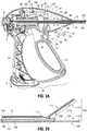
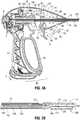
FIG. 1A is a side, perspective view of an endoscopic surgical forceps provided in accordance with the present disclosure;FIG. 1B is an enlarged, side, perspective view of the distal end of the forceps ofFIG. 1 A;FIG. 2A is a side, cross-sectional view of the proximal end of the forceps ofFIG. 1A , wherein the movable handle is disposed in an initial position and the trigger is disposed in an un-actuated position;FIG. 2B is a side, cross-sectional view of the distal end of the forceps ofFIG. 1A , wherein jaw members of the end effector assembly are disposed in a spaced-apart position corresponding to the initial position of the movable handle and wherein a knife is disposed in a retracted position corresponding to the un-actuated position of the trigger;FIG. 3A is a side, cross-sectional view of the proximal end of the forceps ofFIG. 1A , wherein the movable handle is disposed in a depressed position and the trigger is disposed in the un-actuated position;FIG. 3B is a side, cross-sectional view of the distal end of the forceps ofFIG. 1A , wherein the jaw members of the end effector assembly are disposed in an approximated position corresponding to the depressed position of the movable handle and wherein the knife is disposed in a retracted position corresponding to the un-actuated position of the trigger;FIG. 4A is a side, cross-sectional view of the proximal end of the forceps ofFIG. 1A , wherein the movable handle is disposed in an depressed position and the trigger is disposed in a first actuated position;FIG. 4B is a side, cross-sectional view of the distal end of the forceps ofFIG. 1A , wherein the jaw members of the end effector assembly are disposed in the approximated position corresponding to the depressed position of the movable handle and the knife is disposed in a first extended position corresponding to the first actuated position of the trigger;FIG. 5A is a side, cross-sectional view of the proximal end of the forceps ofFIG. 1A , wherein the movable handle is disposed in an depressed position, the trigger is disposed in a second actuated position, and a knife lock assembly is disposed in a locked configuration;FIG. 5B is a side, cross-sectional view of the distal end of the forceps ofFIG. 1A , wherein the jaw members of the end effector assembly are disposed in the approximated position corresponding to the depressed position of the movable handle and the knife is retained in a second extended position corresponding to the second actuated position of the trigger and the locked configuration of the knife lock assembly; andFIG. 6 is a schematic illustration of a robotic surgical system configured for use in conjunction with aspects and features of the present disclosure.- Referring to
FIGS. 1A and 1B , anelectrosurgical forceps 10 for use in connection with endoscopic surgical procedures is shown, althoughforceps 10 may also be configured for use in connection with traditional open surgical procedures and/or with any suitable form of energy.Forceps 10 generally includes ahousing 20, ahandle assembly 30, atrigger assembly 60, aknife lock assembly 80, a rotatingassembly 90, and anend effector assembly 100.End effector assembly 100 includes first andsecond jaw members FIG. 2B ) and an approximated position (FIG. 3B ) for grasping tissue therebetween.Forceps 10 further includes ashaft 12 having adistal end 14 configured to engageend effector assembly 100 and aproximal end 16 that engageshousing 20. Rotatingassembly 90 is rotatable in either direction to rotateend effector assembly 100 relative toshaft 12 andhousing 20 in either direction.Housing 20 houses the internal working components offorceps 10. Forceps 10 also includes anelectrosurgical cable 2 that connectsforceps 10 to a generator (not shown) or other suitable power source, althoughforceps 10 may alternatively be configured as a battery powered instrument.Cable 2 includes a wire (or wires) 4 extending therethrough, intohousing 20 and throughshaft 12, to ultimately connect the source of energy tojaw member 110 and/orjaw member 120 ofend effector assembly 100. Anactivation switch 6 mounted onhousing 20 is electrically coupled betweenend effector assembly 100 andcable 2 so as to enable the selective supply of energy tojaw member 110 and/orjaw member 120, e.g., upon activation ofactivation switch 6. However, other suitable electrical connections and/or configurations for supplying energy tojaw member 110 and/orjaw member 120 may alternatively be provided.End effector assembly 100 is attached atdistal end 14 ofshaft 12 and includes a pair of opposingjaw members End effector assembly 100 is designed as a unilateral assembly, i.e., wherejaw member 120 is fixed relative toshaft 12 andjaw member 110 is moveable relative to bothshaft 12 and fixedjaw member 120. However,end effector assembly 100 may alternatively be configured as a bilateral assembly, i.e., where bothjaw member 110 andjaw member 120 are moveable relative to one another and with respect toshaft 12. Eachjaw member surface Surfaces jaw members jaw members - With additional reference to
FIGS. 2A-3B , handleassembly 30 includes a fixedhandle 50 and amovable handle 40. Fixedhandle 50 is integrally associated withhousing 20 andmovable handle 40 is movable relative to fixedhandle 50.Movable handle 40 is ultimately connected to adrive assembly 160 that, together, mechanically cooperate to impart movement ofjaw members surfaces movable handle 40 includes abifurcated flange portion 42 that is pivotably coupled withinhousing 20 via apivot 44 and is operably coupled withdrive bar 162 ofdrive assembly 160 via adrive mandrel 164 such that pivoting ofmovable handle 40 towards fixedhandle 30 effects longitudinal translation ofdrive mandrel 164 and, thus, drivebar 162 throughhousing 20 andshaft 12.Drive bar 162 is slidably disposed withinshaft 12 and is coupled tojaw member 110 at the distal end thereof such that, asdrive bar 162 is translated proximally throughshaft 12,jaw member 110 is pivoted relative tojaw member 120 from the spaced-apart positon (FIG. 2B ) towards the approximated position (FIG. 3B ). On the other hand, whenmovable handle 40 is released or returned to its initial position relative to fixedhandle 30,drive bar 162 is translated distally, thereby pivotingjaw member 110 relative tojaw member 120 from the approximated position (FIG. 3B ) back towards the spaced-apart position (FIG. 2B ). However, this configuration may be reversed, e.g., where proximal translation ofdrive bar 162 movesjaw members drive bar 162 movesjaw members - As shown in
FIG. 2A ,moveable handle 40 is initially spaced-apart from fixedhandle 50 and, correspondingly,jaw members FIG. 2B ).Moveable handle 40 is depressible from this initial position to a compressed position corresponding to the approximated position ofjaw members 110, 120 (seeFIGS. 3A and 3B ). With tissue grasped betweensurfaces jaw members surfaces activation switch 6, to treat tissue grasped betweenjaw members - Referring to
FIGS. 1A, 1B , and3A-5B , aknife assembly 180 is disposed withinshaft 12 and aknife channel jaw members knife 184 therethrough for cutting tissue grasped betweenjaw members Trigger 62 oftrigger assembly 60 is operably coupled toknife 184 to advanceknife 184 between a retracted position (FIG. 3B ), whereinknife 184 is disposed withinshaft 12, a first extended position (FIG. 4B ), whereinknife 184 extends throughknife channels jaw members 110, 120 (but does not extend distally beyondjaw members 110, 120) to cut tissue grasped therebetween, and a second extended position (FIG. 5B ), whereinknife 184 extends distally fromjaw members knife 184 as a scalpel.Knife channels knife 184 to the second extended position (FIG. 5B ), although other configurations are also contemplated, e.g.,knife 184 may be configured to ramp belowsurface 122 ofjaw member 120 and through an aperture defined within the distal end ofjaw member 120 to permit extension ofknife 184 to the second extended position (FIG. 5B ). Knife assembly 180 further includes aknife bar 182 that is slidably disposed withindrive bar 162.Knife 184 is coupled toknife bar 182 at the proximal end ofknife 184, while the distal end ofknife 184 defines acutting blade 186 configured to facilitate cutting of tissue.Trigger assembly 60 includestrigger 62 pivotably coupled tohousing 20 and movable relative thereto between an un-actuated position (FIG. 3A ), a first actuated position (FIG. 4A ), and a second actuated position (FIG. 5A ) for translatingknife 184 between the retracted position (FIG. 3B ), the first extended position (FIG. 4B ), and the second extended position (FIG. 5B ). More specifically, trigger 62 includes amanipulation portion 63 extending fromhousing 20 to enable actuation oftrigger 62 by a user, a bifurcated flange portion 64 (only one leg of thebifurcated flange portion 64 is illustrated inFIGS. 2A ,3A ,4A , and5A ) to enable illustration of the components disposed therebetween) extending upwardly intohousing 20, and anintermediate portion 65 disposed betweenmanipulation portion 63 andbifurcated flange portion 64 and about which trigger 62 is pivotably coupled tohousing 20. Each leg ofbifurcated flange portion 64 defines aslot 66 therethrough. Apin 67 extends throughslots 66 and between the legs ofbifurcated flange portion 64.Pin 67 is engaged within anannular slot 73 defined withinproximal mandrel 72 ofslider 70.Slider 70 is slidably disposed aboutdrive bar 162 and engaged withknife bar 182, e.g., via a pin (not shown) engaged withslider 70 andknife bar 182 and extending through a slot (not shown) defined within drive bar 162) such that pivoting oftrigger 62 from the un-actuated position (FIG. 3A ) to the first actuated position (FIG. 4A ) urges bifurcatedflange portion 64 distally, thereby urgingproximal mandrel 72 andslider 70 distally and, thus, translatingknife bar 182 distally throughdrive bar 162 andshaft 12 and relative to endeffector assembly 100 to deployknife 184. A biasingmember 68 may be disposed withinhousing 20 and positioned to biasslider 70 proximally, thereby biasingknife 184 towards the retracted position (FIG. 3B ) and trigger 62 towards the un-actuated position (FIG. 3A ).- Continuing with reference to
FIGS. 1A, 1B , and3A-5B ,knife lock assembly 80 includes a lock/unlock actuator 82 including a base 84 slidably disposed withinhousing 20 in generally vertical orientation (generally perpendicular to the longitudinally-extendingshaft 12,drive bar 162, and knife bar 182) and anactuator button 86 disposed at an end ofbase 84 to facilitate actuation of lock/unlock actuator 82. As detailed below, lock/unlockactuator 82 is selectively actuatable to permit movement oftrigger 62 from the un-actuated position (FIG. 3A ) or the first actuated position (FIG. 4A ) to the second actuated position (FIG. 5A ), thus permitting extension ofknife 184 from the retracted position (FIG. 3B ) or the first extended position (FIG. 4B ) to the second extended position (FIG. 5A ). Base 84 of lock/unlock actuator 82 ofknife lock assembly 80 defines avertical slot 88 therein so as to permit passage of drive bar 162 (andknife bar 182, which is disposed within drive bar 162) therethrough. Initially, in a locked position ofactuator 82,vertical slot 88 is off-center relative to drivebar 162 such that at least a portion ofbase 84 inhibits the translation ofslider 70 so as to inhibit actuation oftrigger 62 beyond the first actuated position (FIG. 4A ), thereby inhibiting extension ofknife 184 beyond the first extended position (FIG. 4B ). More specifically,base 84 interferes withdistal mandrel 74 ofslider 70 to inhibit further distal translation thereof beyond the first actuated position of trigger 62 (FIG. 4A ) and the first extended position of knife 184 (FIG. 4B ). A biasingmember 89 disposed withinhousing 20 and connected betweenhousing 20 and the free end ofbase 84 biases base 84 downwardly corresponding to the off-center positioning ofvertical slot 88, e.g., the locked position ofactuator 82.- Lock/
unlock actuator 82 ofknife lock assembly 80 is movable, e.g., via depression ofactuator button 86 towardshousing 20, against the bias of biasingmember 89 from the locked position (FIGS. 3A ,4A , and5A ) to an unlocked position, whereinvertical slot 88 is centered relative to drivebar 162. In this centered position ofvertical slot 88,distal mandrel 74 ofslider 70 is capable of extending at least partially throughvertical slot 88, sufficiently so as to permit movement oftrigger 62 from the un-actuated position (FIG. 3A ) or the first actuated position (FIG. 4A ) to the second actuated position (FIG. 5A ), thus permitting extension ofknife 184 from the retracted position (FIG. 3B ) or the first extended position (FIG. 4B ) to the second extended position (FIG. 5B ). As noted above, actuation oftrigger 62 to the second actuated position (FIG. 5A ) movesknife 184 to the second extended position (FIG. 5B ). In this position,slider 70 is positioned such thatannular slot 76 defined withindistal mandrel 74 is disposed withinslot 88 ofbase 84 of lock/unlock actuator 82. Thus, upon release of lock/unlock actuator 82, biasingmember 89 urges lock/unlock actuator 82 to return to the locked position, whereinvertical slot 88 is moved to the off-center position relative to drivebar 162. Withannular slot 76 ofdistal mandrel 74 ofslider 70 disposed withinslot 88 ofbase 84, such return of lock/unlock actuator 82 to the locked position retainsslider 70 in position corresponding to the second actuated position of trigger 62 (FIG. 5A ) and the second extended position of knife 184 (FIG. 5B ) due to interference betweendistal mandrel 74 on either side of base 84 (which is received withinannular slot 76 of distal mandrel 74). Accordingly, withknife 184 locked in the second extended position (FIG. 5B ),knife 184 may be utilized as a scalpel, for example, to cut through tissue layers to reach tissue to be treated. - In order to release
knife 184 from the second extended position (FIG. 5B ), lock/unlockactuator 82 is once again depressed towardshousing 20 to the unlocked position, whereinvertical slot 88 is centered relative to drivebar 162. In this centered position ofvertical slot 88, similarly as detailed above, sufficient clearance is provided so as to enabledistal mandrel 74 and, thus,slider 70 to return proximally relative to lock/unlock actuator 82 to the un-actuated position (FIG. 3A ) or first actuated position (FIG. 4A ). Once the un-actuated position (FIG. 3A ) or first actuated position (FIG. 4A ) has been achieved, lock/unlockactuator 82 may be released, allowing lock/unlock actuator 82 to return to its biased, locked position. With lock/unlock actuator 82 returned to the locked position, trigger 62 is once again confined to movement between the un-actuated position (FIG. 3A ) and the first actuated position (FIG. 4A ) and, accordingly,knife 184 is confined to movement between the retracted position (FIG. 3B ) and the first extended position (FIG. 4B ). - The various embodiments disclosed herein may also be configured to work with robotic surgical systems and what is commonly referred to as "Telesurgery." Such systems employ various robotic elements to assist the surgeon and allow remote operation (or partial remote operation) of surgical instrumentation. Various robotic arms, gears, cams, pulleys, electric and mechanical motors, etc. may be employed for this purpose and may be designed with a robotic surgical system to assist the surgeon during the course of an operation or treatment. Such robotic systems may include remotely steerable systems, automatically flexible surgical systems, remotely flexible surgical systems, remotely articulating surgical systems, wireless surgical systems, modular or selectively configurable remotely operated surgical systems, etc.
- The robotic surgical systems may be employed with one or more consoles that are next to the operating theater or located in a remote location. In this instance, one team of surgeons or nurses may prep the patient for surgery and configure the robotic surgical system with one or more of the instruments disclosed herein while another surgeon (or group of surgeons) remotely control(s) the instruments via the robotic surgical system. As can be appreciated, a highly skilled surgeon may perform multiple operations in multiple locations without leaving his/her remote console which can be both economically advantageous and a benefit to the patient or a series of patients.
- The robotic arms of the surgical system are typically coupled to a pair of master handles by a controller. The handles can be moved by the surgeon to produce a corresponding movement of the working ends of any type of surgical instrument (e.g., end effectors, graspers, knifes, scissors, etc.) which may complement the use of one or more of the embodiments described herein. The movement of the master handles may be scaled so that the working ends have a corresponding movement that is different, smaller or larger, than the movement performed by the operating hands of the surgeon. The scale factor or gearing ratio may be adjustable so that the operator can control the resolution of the working ends of the surgical instrument(s).
- The master handles may include various sensors to provide feedback to the surgeon relating to various tissue parameters or conditions, e.g., tissue resistance due to manipulation, cutting or otherwise treating, pressure by the instrument onto the tissue, tissue temperature, tissue impedance, etc. As can be appreciated, such sensors provide the surgeon with enhanced tactile feedback simulating actual operating conditions. The master handles may also include a variety of different actuators for delicate tissue manipulation or treatment further enhancing the surgeon's ability to mimic actual operating conditions.
- Referring to
FIG. 6 , a medical work station is shown generally aswork station 1000 and generally may include a plurality ofrobot arms control device 1004; and anoperating console 1005 coupled withcontrol device 1004.Operating console 1005 may include adisplay device 1006, which may be set up in particular to display three-dimensional images; andmanual input devices robot arms - Each of the
robot arms device end effector 1100, in accordance with any one of several embodiments disclosed herein, as will be described in greater detail below. Robot arms device 1004. Control device 1004 (e.g., a computer) may be set up to activate the drives, in particular by means of a computer program, in such a way thatrobot arms devices manual input devices Control device 1004 may also be set up in such a way that it regulates the movement ofrobot arms Medical work station 1000 may be configured for use on apatient 1013 lying on a patient table 1012 to be treated in a minimally invasive manner by means ofend effector 1100.Medical work station 1000 may also include more than tworobot arms device 1004 and being telemanipulatable by means ofoperating console 1005. A medical instrument or surgical tool (including an end effector 1100) may also be attached to the additional robot arm.Medical work station 1000 may include adatabase 1014, in particular coupled to withcontrol device 1004, in which are stored, for example, preoperative data from patient/living being 1013 and/or anatomical atlases.- From the foregoing and with reference to the various figure drawings, those skilled in the art will appreciate that certain modifications can also be made to the present disclosure without departing from the scope of the same. While several embodiments of the disclosure have been shown in the drawings, it is not intended that the disclosure be limited thereto, as it is intended that the disclosure be as broad in scope as the art will allow and that the specification be read likewise. Therefore, the above description should not be construed as limiting, but merely as exemplifications of particular embodiments. Those skilled in the art will envision other modifications within the scope of the claims appended hereto.
Claims (15)
- A surgical forceps (10), comprising:a housing (20);a shaft (12) extending distally from the housing;an end effector assembly (100) disposed at a distal end of the shaft and including first and second jaw members (110, 120) configured for grasping tissue therebetween;a knife assembly (180) disposed within the shaft and including a knife bar (182) having a knife (184) disposed at a distal end thereof, the knife bar longitudinally translatable through the shaft and relative to the end effector assembly to translate the knife between a retracted position, wherein the knife is disposed proximally of the end effector assembly, a first extended position, wherein the knife extends between the first and second jaw members, and a second extended position, wherein the knife extends distally from the first and second jaw members;a trigger assembly (60) associated with the housing and including a trigger operably coupled with the knife bar such that movement of the trigger between an un-actuated position, a first actuated position, and a second actuated position moves the knife between the retracted position, the first extended position, and the second extended position, respectively; anda knife lock assembly (80) associated with the housing, the knife lock assembly including an actuator (82) movable between a locked position and an unlocked position and configured to selectively permit movement of the knife between the retracted position or first extended position and the second extended position.
- The forceps according to claim 1, wherein the trigger assembly includes a slider (70) coupled between the trigger and the knife bar,
wherein, with the trigger disposed in the un-actuated position or the first actuated position and the actuator disposed in the locked position, the actuator interferes with the slider to inhibit movement of the trigger to the second actuated position,
wherein, with the trigger disposed in the second actuated position and the actuator disposed in the locked position, the actuator engages the slider to inhibit movement of the slider, thereby retaining the trigger in the second actuated position, and
wherein, with actuator disposed in the unlocked position, the actuator permits translation of the slider therethrough such that the trigger is movable between the un-actuated position or the first actuated position and the second actuated position. - The forceps according to claim 2, wherein the slider includes a proximal mandrel (74) operably coupling the trigger with the knife bar and a distal mandrel operably associated with the actuator.
- The forceps according to claim 1, 2 or 3, wherein the actuator is biased towards the locked position.
- The forceps according to any preceding claim, wherein the actuator includes an actuator button (86) disposed on the housing, the actuator button selectively depressible relative to the housing to move the actuator from the locked position to the unlocked position.
- The forceps according to any preceding claim, further including:a drive assembly (160) including a drive bar (162) slidably disposed within the shaft, the drive bar coupled to at least one of the first and second jaw members at a distal end thereof; anda handle assembly (30) associated with the housing and including a movable handle (40) operably coupled with the drive bar, the movable handle movable between an initial position and a compressed position for moving the first and second jaw members from a spaced-apart position to an approximated position for grasping tissue therebetween.
- The forceps according to any preceding claim, wherein each of the first and second jaw members includes an electrically-conductive surface (112, 122) adapted to connect to a source of energy for treating tissue grasped between the first and second jaw members.
- The forceps according to any preceding claim, wherein each of the first and second jaw members defines a knife slot configured to permit reciprocation of the knife therethrough.
- The forceps according to claim 1, comprising:a slider (70) operably coupled to the knife bar;wherein, in the locked position, the actuator interferes with the slider to inhibit movement of the trigger from the un-actuated position or the first actuated position to the second actuated position, and wherein, in the unlocked position, the actuator permits movement of the trigger between the un-actuated position or the first actuated position and the second actuated position.
- The forceps according to claim 9, wherein the slider includes a proximal mandrel (74) operably coupling the trigger with the knife bar and a distal mandrel operably associated with the actuator.
- The forceps according to claim 9 or 10, wherein the actuator is biased towards the locked position.
- The forceps according to any of claims 9 to 11, wherein the actuator includes an actuator button (86) disposed on the housing, the actuator button selectively depressible relative to the housing to move the actuator from the locked position to the unlocked position.
- The forceps according to any of claims 9 to 12, further including:a drive assembly (160) including a drive bar (162) slidably disposed within the shaft, the drive bar coupled to at least one of the first and second jaw members at a distal end thereof; anda handle assembly (30) associated with the housing and including a movable handle (40) operably coupled with the drive bar, the movable handle movable between an initial position and a compressed position for moving the first and second jaw members from a spaced-apart position to an approximated position for grasping tissue therebetween.
- The forceps according to any of claims 9 to 13, wherein each of the first and second jaw members includes an electrically-conductive surface (112, 122) adapted to connect to a source of energy for treating tissue grasped between the first and second jaw members.
- The forceps according to any one of claims 9 to 14, wherein each of the first and second jaw members defines a knife slot (66) configured to permit reciprocation of the knife therethrough.
Applications Claiming Priority (1)
| Application Number | Priority Date | Filing Date | Title |
|---|---|---|---|
| US14/657,553US10206736B2 (en) | 2015-03-13 | 2015-03-13 | Surgical forceps with scalpel functionality |
Publications (2)
| Publication Number | Publication Date |
|---|---|
| EP3072467A1 EP3072467A1 (en) | 2016-09-28 |
| EP3072467B1true EP3072467B1 (en) | 2017-09-20 |
Family
ID=55527382
Family Applications (1)
| Application Number | Title | Priority Date | Filing Date |
|---|---|---|---|
| EP16159789.3AActiveEP3072467B1 (en) | 2015-03-13 | 2016-03-11 | Surgical forceps with scalpel functionality |
Country Status (2)
| Country | Link |
|---|---|
| US (1) | US10206736B2 (en) |
| EP (1) | EP3072467B1 (en) |
Families Citing this family (14)
| Publication number | Priority date | Publication date | Assignee | Title |
|---|---|---|---|---|
| IL269091B2 (en) | 2017-03-08 | 2024-04-01 | Momentis Surgical Ltd | Electrosurgery device |
| US11350977B2 (en) | 2017-03-08 | 2022-06-07 | Memic Innovative Surgery Ltd. | Modular electrosurgical device |
| US11172980B2 (en) | 2017-05-12 | 2021-11-16 | Covidien Lp | Electrosurgical forceps for grasping, treating, and/or dividing tissue |
| US10973567B2 (en)* | 2017-05-12 | 2021-04-13 | Covidien Lp | Electrosurgical forceps for grasping, treating, and/or dividing tissue |
| US10849641B2 (en) | 2018-03-30 | 2020-12-01 | Gyrus Acmi, Inc. | Forceps including a pre-loaded handle latch |
| US11471211B2 (en) | 2018-10-12 | 2022-10-18 | Covidien Lp | Electrosurgical forceps |
| US11376062B2 (en) | 2018-10-12 | 2022-07-05 | Covidien Lp | Electrosurgical forceps |
| CA3120184A1 (en)* | 2018-11-15 | 2020-05-22 | Applied Medical Resources Corporation | Laparoscopic grasper with force-limiting grasping mechanism |
| US11350982B2 (en) | 2018-12-05 | 2022-06-07 | Covidien Lp | Electrosurgical forceps |
| US11523861B2 (en) | 2019-03-22 | 2022-12-13 | Covidien Lp | Methods for manufacturing a jaw assembly for an electrosurgical forceps |
| US11648023B2 (en)* | 2020-02-10 | 2023-05-16 | Covidien Lp | Drive mechanisms for surgical instruments |
| US11969203B2 (en)* | 2020-02-14 | 2024-04-30 | Covidien Lp | Colpotomy system with applied energy |
| US11622804B2 (en) | 2020-03-16 | 2023-04-11 | Covidien Lp | Forceps with linear trigger mechanism |
| WO2025057110A1 (en)* | 2023-09-13 | 2025-03-20 | Covidien Lp | Trigger safety and kickout mechanism for surgical instruments and surgical instruments incorporating the same |
Family Cites Families (172)
| Publication number | Priority date | Publication date | Assignee | Title |
|---|---|---|---|---|
| SU401367A1 (en) | 1971-10-05 | 1973-10-12 | Тернопольский государственный медицинский институт | BIAKTIVNYE ELECTRO SURGICAL INSTRUMENT |
| DE2415263A1 (en) | 1974-03-29 | 1975-10-02 | Aesculap Werke Ag | Surgical H.F. coagulation probe has electrode tongs - with exposed ends of insulated conductors forming tong-jaws |
| DE2514501A1 (en) | 1975-04-03 | 1976-10-21 | Karl Storz | Bipolar coagulation instrument for endoscopes - has two high frequency electrodes looped over central insulating piece |
| FR2315286A2 (en) | 1975-06-26 | 1977-01-21 | Lamidey Marcel | H.F. blood coagulating dissecting forceps - with adjustable stops to vary clamping space and circuit making contacts |
| USD249549S (en) | 1976-10-22 | 1978-09-19 | Aspen Laboratories, Inc. | Electrosurgical handle |
| USD263020S (en) | 1980-01-22 | 1982-02-16 | Rau Iii David M | Retractable knife |
| US4671274A (en) | 1984-01-30 | 1987-06-09 | Kharkovsky Nauchno-Issledovatelsky Institut Obschei I | Bipolar electrosurgical instrument |
| DE3423356C2 (en) | 1984-06-25 | 1986-06-26 | Berchtold Medizin-Elektronik GmbH & Co, 7200 Tuttlingen | Electrosurgical high frequency cutting instrument |
| US4657016A (en) | 1984-08-20 | 1987-04-14 | Garito Jon C | Electrosurgical handpiece for blades, needles and forceps |
| USD299413S (en) | 1985-07-17 | 1989-01-17 | The Stanley Works | Folding pocket saw handle |
| USD295893S (en) | 1985-09-25 | 1988-05-24 | Acme United Corporation | Disposable surgical clamp |
| USD295894S (en) | 1985-09-26 | 1988-05-24 | Acme United Corporation | Disposable surgical scissors |
| DE3627221A1 (en) | 1986-01-15 | 1988-02-18 | Siemens Ag | HF SURGERY DEVICE WITH POWER CONTROL FROM THE SURGICAL HANDLE |
| USD298353S (en) | 1986-05-06 | 1988-11-01 | Vitalmetrics, Inc. | Handle for surgical instrument |
| DE8712328U1 (en) | 1987-09-11 | 1988-02-18 | Jakoubek, Franz, 7201 Emmingen-Liptingen | Endoscopy forceps |
| US5919202A (en) | 1989-12-05 | 1999-07-06 | Yoon; Inbae | Surgical instrument with jaws and movable internal needle and method for use thereof |
| US5893863A (en) | 1989-12-05 | 1999-04-13 | Yoon; Inbae | Surgical instrument with jaws and movable internal hook member for use thereof |
| JP2806511B2 (en) | 1990-07-31 | 1998-09-30 | 松下電工株式会社 | Manufacturing method of sintered alloy |
| US5389102A (en) | 1990-09-13 | 1995-02-14 | United States Surgical Corporation | Apparatus and method for subcuticular stapling of body tissue |
| US5190541A (en) | 1990-10-17 | 1993-03-02 | Boston Scientific Corporation | Surgical instrument and method |
| JP2951418B2 (en) | 1991-02-08 | 1999-09-20 | トキコ株式会社 | Sample liquid component analyzer |
| US5330471A (en) | 1991-06-07 | 1994-07-19 | Hemostatic Surgery Corporation | Bi-polar electrosurgical endoscopic instruments and methods of use |
| USD348930S (en) | 1991-10-11 | 1994-07-19 | Ethicon, Inc. | Endoscopic stapler |
| JPH0630945A (en) | 1992-05-19 | 1994-02-08 | Olympus Optical Co Ltd | Suturing apparatus |
| US5312391A (en) | 1992-07-29 | 1994-05-17 | Wilk Peter J | Laparoscopic instrument assembly |
| US5318040A (en) | 1992-08-27 | 1994-06-07 | Kensey Nash Corporation | Instruments and methods for performing medical procedures via small percutaneous incisions or punctures without using a trocar |
| USD349341S (en) | 1992-10-28 | 1994-08-02 | Microsurge, Inc. | Endoscopic grasper |
| DE4303882C2 (en) | 1993-02-10 | 1995-02-09 | Kernforschungsz Karlsruhe | Combination instrument for separation and coagulation for minimally invasive surgery |
| US5445638B1 (en) | 1993-03-08 | 1998-05-05 | Everest Medical Corp | Bipolar coagulation and cutting forceps |
| JP3390041B2 (en) | 1993-04-05 | 2003-03-24 | オリンパス光学工業株式会社 | Forceps |
| GB9309142D0 (en) | 1993-05-04 | 1993-06-16 | Gyrus Medical Ltd | Laparoscopic instrument |
| USD343453S (en) | 1993-05-05 | 1994-01-18 | Laparomed Corporation | Handle for laparoscopic surgical instrument |
| USD354564S (en) | 1993-06-25 | 1995-01-17 | Richard-Allan Medical Industries, Inc. | Surgical clip applier |
| US5693051A (en) | 1993-07-22 | 1997-12-02 | Ethicon Endo-Surgery, Inc. | Electrosurgical hemostatic device with adaptive electrodes |
| US5688270A (en) | 1993-07-22 | 1997-11-18 | Ethicon Endo-Surgery,Inc. | Electrosurgical hemostatic device with recessed and/or offset electrodes |
| GB9322464D0 (en) | 1993-11-01 | 1993-12-22 | Gyrus Medical Ltd | Electrosurgical apparatus |
| USD358887S (en) | 1993-12-02 | 1995-05-30 | Cobot Medical Corporation | Combined cutting and coagulating forceps |
| DE4403252A1 (en) | 1994-02-03 | 1995-08-10 | Michael Hauser | Instrument shaft for min. invasive surgery |
| GB9413070D0 (en) | 1994-06-29 | 1994-08-17 | Gyrus Medical Ltd | Electrosurgical apparatus |
| USD384413S (en) | 1994-10-07 | 1997-09-30 | United States Surgical Corporation | Endoscopic suturing instrument |
| GB9425781D0 (en) | 1994-12-21 | 1995-02-22 | Gyrus Medical Ltd | Electrosurgical instrument |
| DE19506363A1 (en) | 1995-02-24 | 1996-08-29 | Frost Lore Geb Haupt | Non-invasive thermometry in organs under hyperthermia and coagulation conditions |
| JPH08289895A (en) | 1995-04-21 | 1996-11-05 | Olympus Optical Co Ltd | Suture device |
| DE19515914C1 (en) | 1995-05-02 | 1996-07-25 | Aesculap Ag | Tong or scissor-shaped surgical instrument |
| JPH09538A (en) | 1995-06-21 | 1997-01-07 | Fuji Photo Optical Co Ltd | High-frequency medical treatment instrument |
| US6293942B1 (en) | 1995-06-23 | 2001-09-25 | Gyrus Medical Limited | Electrosurgical generator method |
| JPH1024051A (en) | 1995-09-20 | 1998-01-27 | Olympus Optical Co Ltd | Coagulation forceps with separating function |
| USH1745H (en) | 1995-09-29 | 1998-08-04 | Paraschac; Joseph F. | Electrosurgical clamping device with insulation limited bipolar electrode |
| AU703455B2 (en) | 1995-10-20 | 1999-03-25 | Ethicon Endo-Surgery, Inc. | Self protecting knife for curved jaw surgical instruments |
| US5673842A (en) | 1996-03-05 | 1997-10-07 | Ethicon Endo-Surgery | Surgical stapler with locking mechanism |
| DE19608716C1 (en) | 1996-03-06 | 1997-04-17 | Aesculap Ag | Bipolar surgical holding instrument |
| USD408018S (en) | 1996-03-12 | 1999-04-13 | Mcnaughton Patrick J | Switch guard |
| USD416089S (en) | 1996-04-08 | 1999-11-02 | Richard-Allan Medical Industries, Inc. | Endoscopic linear stapling and dividing surgical instrument |
| DE29616210U1 (en) | 1996-09-18 | 1996-11-14 | Olympus Winter & Ibe Gmbh, 22045 Hamburg | Handle for surgical instruments |
| US5923475A (en) | 1996-11-27 | 1999-07-13 | Eastman Kodak Company | Laser printer using a fly's eye integrator |
| JP3836551B2 (en) | 1996-12-04 | 2006-10-25 | ペンタックス株式会社 | Endoscopic hot biopsy forceps |
| US5891142A (en) | 1996-12-06 | 1999-04-06 | Eggers & Associates, Inc. | Electrosurgical forceps |
| USH2037H1 (en) | 1997-05-14 | 2002-07-02 | David C. Yates | Electrosurgical hemostatic device including an anvil |
| USH1904H (en) | 1997-05-14 | 2000-10-03 | Ethicon Endo-Surgery, Inc. | Electrosurgical hemostatic method and device |
| JP3986126B2 (en) | 1997-08-04 | 2007-10-03 | オリンパス株式会社 | Endoscopic surgical instrument |
| JP3986127B2 (en) | 1997-08-06 | 2007-10-03 | オリンパス株式会社 | Endoscopic surgical instrument |
| DE19738457B4 (en) | 1997-09-03 | 2009-01-02 | Celon Ag Medical Instruments | Method and device for in vivo deep coagulation of biological tissue volumes while sparing the tissue surface with high frequency alternating current |
| USD402028S (en) | 1997-10-10 | 1998-12-01 | Invasatec, Inc. | Hand controller for medical system |
| US5980510A (en) | 1997-10-10 | 1999-11-09 | Ethicon Endo-Surgery, Inc. | Ultrasonic clamp coagulator apparatus having improved clamp arm pivot mount |
| DE19751108A1 (en) | 1997-11-18 | 1999-05-20 | Beger Frank Michael Dipl Desig | Electrosurgical operation tool, especially for diathermy |
| JPH11169381A (en) | 1997-12-15 | 1999-06-29 | Olympus Optical Co Ltd | High frequency treating device |
| EP0923907A1 (en) | 1997-12-19 | 1999-06-23 | Gyrus Medical Limited | An electrosurgical instrument |
| US6679882B1 (en) | 1998-06-22 | 2004-01-20 | Lina Medical Aps | Electrosurgical device for coagulating and for making incisions, a method of severing blood vessels and a method of coagulating and for making incisions in or severing tissue |
| JP4225624B2 (en) | 1998-08-27 | 2009-02-18 | オリンパス株式会社 | High frequency treatment device |
| USD424694S (en) | 1998-10-23 | 2000-05-09 | Sherwood Services Ag | Forceps |
| USD449886S1 (en) | 1998-10-23 | 2001-10-30 | Sherwood Services Ag | Forceps with disposable electrode |
| USD425201S (en) | 1998-10-23 | 2000-05-16 | Sherwood Services Ag | Disposable electrode assembly |
| AU756626B2 (en) | 1998-10-23 | 2003-01-16 | Covidien Ag | Open vessel sealing forceps with disposable electrodes |
| DE19858512C1 (en) | 1998-12-18 | 2000-05-25 | Storz Karl Gmbh & Co Kg | Bipolar medical instrument for minimally invasive surgery for endoscopic operations; has mutually insulated leads passing through tubular shaft to conductor elements on linked jaw parts |
| US6190386B1 (en) | 1999-03-09 | 2001-02-20 | Everest Medical Corporation | Electrosurgical forceps with needle electrodes |
| DE19915061A1 (en) | 1999-04-01 | 2000-10-26 | Erbe Elektromedizin | Surgical instrument |
| GB9911954D0 (en) | 1999-05-21 | 1999-07-21 | Gyrus Medical Ltd | Electrosurgery system and instrument |
| GB9911956D0 (en) | 1999-05-21 | 1999-07-21 | Gyrus Medical Ltd | Electrosurgery system and method |
| GB9912627D0 (en) | 1999-05-28 | 1999-07-28 | Gyrus Medical Ltd | An electrosurgical instrument |
| GB9912625D0 (en) | 1999-05-28 | 1999-07-28 | Gyrus Medical Ltd | An electrosurgical generator and system |
| GB9913652D0 (en) | 1999-06-11 | 1999-08-11 | Gyrus Medical Ltd | An electrosurgical generator |
| JP2001003400A (en) | 1999-06-21 | 2001-01-09 | Sumitomo Constr Mach Co Ltd | Monitor device for hydraulic shovel |
| JP2001029355A (en) | 1999-07-21 | 2001-02-06 | Olympus Optical Co Ltd | Electric cautery device |
| DE19940689A1 (en) | 1999-08-27 | 2001-04-05 | Storz Karl Gmbh & Co Kg | Bipolar medical instrument |
| USD465281S1 (en) | 1999-09-21 | 2002-11-05 | Karl Storz Gmbh & Co. Kg | Endoscopic medical instrument |
| DE19946527C1 (en) | 1999-09-28 | 2001-07-12 | Storz Karl Gmbh & Co Kg | Bipolar, e.g. laparoscopic surgery instrument, cuts electrically, cauterizes and grips using simple design with high frequency current-concentrating projections |
| JP4315557B2 (en) | 2000-01-12 | 2009-08-19 | オリンパス株式会社 | Medical treatment tool |
| DE10003020C2 (en) | 2000-01-25 | 2001-12-06 | Aesculap Ag & Co Kg | Bipolar barrel instrument |
| DE10031773B4 (en) | 2000-05-04 | 2007-11-29 | Erbe Elektromedizin Gmbh | Surgical gripping instrument, in particular tweezers or forceps |
| DE10027727C1 (en) | 2000-06-03 | 2001-12-06 | Aesculap Ag & Co Kg | Scissors-shaped or forceps-shaped surgical instrument |
| DE10045375C2 (en) | 2000-09-14 | 2002-10-24 | Aesculap Ag & Co Kg | Medical instrument |
| AU2002246923A1 (en) | 2000-10-20 | 2002-07-30 | Onux Medical, Inc. | Surgical suturing instrument and method of use |
| JP3523839B2 (en) | 2000-10-30 | 2004-04-26 | オリンパス株式会社 | Surgical instruments |
| USD453923S1 (en) | 2000-11-16 | 2002-02-26 | Carling Technologies, Inc. | Electrical rocker switch guard |
| DE10061278B4 (en) | 2000-12-08 | 2004-09-16 | GFD-Gesellschaft für Diamantprodukte mbH | Instrument for surgical purposes |
| US6554829B2 (en) | 2001-01-24 | 2003-04-29 | Ethicon, Inc. | Electrosurgical instrument with minimally invasive jaws |
| US6464702B2 (en) | 2001-01-24 | 2002-10-15 | Ethicon, Inc. | Electrosurgical instrument with closing tube for conducting RF energy and moving jaws |
| US20020111624A1 (en) | 2001-01-26 | 2002-08-15 | Witt David A. | Coagulating electrosurgical instrument with tissue dam |
| DE20121161U1 (en) | 2001-01-31 | 2002-04-04 | Olympus Winter & Ibe Gmbh, 22045 Hamburg | Endoscopic instrument |
| USD466209S1 (en) | 2001-02-27 | 2002-11-26 | Visionary Biomedical, Inc. | Steerable catheter |
| USD454951S1 (en) | 2001-02-27 | 2002-03-26 | Visionary Biomedical, Inc. | Steerable catheter |
| USD457959S1 (en) | 2001-04-06 | 2002-05-28 | Sherwood Services Ag | Vessel sealer |
| USD457958S1 (en) | 2001-04-06 | 2002-05-28 | Sherwood Services Ag | Vessel sealer and divider |
| FR2828248B1 (en) | 2001-08-02 | 2003-11-14 | Peugeot Citroen Automobiles Sa | PIVOT LINK BETWEEN TWO PARTS |
| US6616661B2 (en) | 2001-09-28 | 2003-09-09 | Ethicon, Inc. | Surgical device for clamping, ligating, and severing tissue |
| JP2003116871A (en) | 2001-10-16 | 2003-04-22 | Olympus Optical Co Ltd | Surgical tool |
| US6676660B2 (en) | 2002-01-23 | 2004-01-13 | Ethicon Endo-Surgery, Inc. | Feedback light apparatus and method for use with an electrosurgical instrument |
| EP1795140B1 (en) | 2002-10-04 | 2017-02-22 | Covidien AG | Electrode assembly for sealing and cutting tissue |
| JP2003175052A (en) | 2002-11-01 | 2003-06-24 | Olympus Optical Co Ltd | Coagulation treatment tool |
| USD493888S1 (en) | 2003-02-04 | 2004-08-03 | Sherwood Services Ag | Electrosurgical pencil with pistol grip |
| USD499181S1 (en) | 2003-05-15 | 2004-11-30 | Sherwood Services Ag | Handle for a vessel sealer and divider |
| USD496997S1 (en) | 2003-05-15 | 2004-10-05 | Sherwood Services Ag | Vessel sealer and divider |
| USD502994S1 (en) | 2003-05-21 | 2005-03-15 | Blake, Iii Joseph W | Repeating multi-clip applier |
| US7150749B2 (en) | 2003-06-13 | 2006-12-19 | Sherwood Services Ag | Vessel sealer and divider having elongated knife stroke and safety cutting mechanism |
| US7510562B2 (en) | 2003-07-08 | 2009-03-31 | Terumo Corporation | Vein dissector, cauterizing and ligating apparatus for endoscopic harvesting of blood vessels |
| USD545432S1 (en) | 2003-08-08 | 2007-06-26 | Olympus Corporation | Distal portion of hemostatic forceps for endoscope |
| USD509297S1 (en) | 2003-10-17 | 2005-09-06 | Tyco Healthcare Group, Lp | Surgical instrument |
| US7367976B2 (en) | 2003-11-17 | 2008-05-06 | Sherwood Services Ag | Bipolar forceps having monopolar extension |
| US7232440B2 (en)* | 2003-11-17 | 2007-06-19 | Sherwood Services Ag | Bipolar forceps having monopolar extension |
| US7442193B2 (en) | 2003-11-20 | 2008-10-28 | Covidien Ag | Electrically conductive/insulative over-shoe for tissue fusion |
| JP4624697B2 (en) | 2004-03-12 | 2011-02-02 | オリンパス株式会社 | Surgical instrument |
| USD541938S1 (en) | 2004-04-09 | 2007-05-01 | Sherwood Services Ag | Open vessel sealer with mechanical cutter |
| JP2005312807A (en) | 2004-04-30 | 2005-11-10 | Olympus Corp | Energy therapy device |
| DE102004026179B4 (en) | 2004-05-14 | 2009-01-22 | Erbe Elektromedizin Gmbh | Electrosurgical instrument |
| USD533942S1 (en) | 2004-06-30 | 2006-12-19 | Sherwood Services Ag | Open vessel sealer with mechanical cutter |
| JP2006015078A (en) | 2004-07-05 | 2006-01-19 | Olympus Corp | Medical apparatus |
| DE102004040959B4 (en) | 2004-08-24 | 2008-12-24 | Erbe Elektromedizin Gmbh | Surgical instrument |
| DE102004049243B4 (en)* | 2004-10-01 | 2008-07-10 | Fabrizio Dr. Caroli | Surgical instrument |
| USD535027S1 (en) | 2004-10-06 | 2007-01-09 | Sherwood Services Ag | Low profile vessel sealing and cutting mechanism |
| USD541418S1 (en) | 2004-10-06 | 2007-04-24 | Sherwood Services Ag | Lung sealing device |
| USD525361S1 (en) | 2004-10-06 | 2006-07-18 | Sherwood Services Ag | Hemostat style elongated dissecting and dividing instrument |
| USD531311S1 (en) | 2004-10-06 | 2006-10-31 | Sherwood Services Ag | Pistol grip style elongated dissecting and dividing instrument |
| USD567943S1 (en) | 2004-10-08 | 2008-04-29 | Sherwood Services Ag | Over-ratchet safety for a vessel sealing instrument |
| USD533274S1 (en) | 2004-10-12 | 2006-12-05 | Allegiance Corporation | Handle for surgical suction-irrigation device |
| USD564662S1 (en) | 2004-10-13 | 2008-03-18 | Sherwood Services Ag | Hourglass-shaped knife for electrosurgical forceps |
| USD582038S1 (en) | 2004-10-13 | 2008-12-02 | Medtronic, Inc. | Transurethral needle ablation device |
| USD538932S1 (en) | 2005-06-30 | 2007-03-20 | Medical Action Industries Inc. | Surgical needle holder |
| USD541611S1 (en) | 2006-01-26 | 2007-05-01 | Robert Bosch Gmbh | Cordless screwdriver |
| CN101420914B (en) | 2006-04-11 | 2011-06-29 | 爱尔伯电子医疗设备公司 | Multi-function device for endoscopic surgery |
| JP4701401B2 (en) | 2006-08-31 | 2011-06-15 | 国立大学法人滋賀医科大学 | Microwave surgical device |
| USD547154S1 (en) | 2006-09-08 | 2007-07-24 | Winsource Industries Limited | Rotary driving tool |
| JP5149903B2 (en) | 2006-10-05 | 2013-02-20 | エルベ・エレクトロメディティン・ゲゼルシャフト・ミット・ベシュレンクテル・ハフツング | Medical equipment |
| USD575395S1 (en) | 2007-02-15 | 2008-08-19 | Tyco Healthcare Group Lp | Hemostat style elongated dissecting and dividing instrument |
| USD649249S1 (en) | 2007-02-15 | 2011-11-22 | Tyco Healthcare Group Lp | End effectors of an elongated dissecting and dividing instrument |
| USD575401S1 (en) | 2007-06-12 | 2008-08-19 | Tyco Healthcare Group Lp | Vessel sealer |
| DE202007009317U1 (en) | 2007-06-26 | 2007-08-30 | Aesculap Ag & Co. Kg | Surgical instrument |
| DE202007009318U1 (en) | 2007-06-26 | 2007-08-30 | Aesculap Ag & Co. Kg | Surgical instrument |
| DE202007009165U1 (en) | 2007-06-29 | 2007-08-30 | Kls Martin Gmbh + Co. Kg | Surgical instrument e.g. tube shaft, for use in e.g. high frequency coagulation instrument, has separator inserted through opening such that largest extension of opening transverse to moving direction corresponds to dimension of separator |
| DE202007016233U1 (en) | 2007-11-20 | 2008-01-31 | Aesculap Ag & Co. Kg | Surgical forceps |
| DE102008018406B3 (en) | 2008-04-10 | 2009-07-23 | Bowa-Electronic Gmbh & Co. Kg | Electrosurgical device |
| DE102008030285A1 (en) | 2008-06-30 | 2009-12-31 | Celon Ag Medical Instruments | Electrosurgical instrument |
| CN201299462Y (en) | 2008-10-28 | 2009-09-02 | 宋洪海 | Multi-layer metal composite pot |
| US20100185196A1 (en) | 2009-01-21 | 2010-07-22 | Satomi Sakao | Medical treatment apparatus, treatment instrument and treatment method for living tissue using energy |
| USD621503S1 (en) | 2009-04-28 | 2010-08-10 | Tyco Healthcare Group Ip | Pistol grip laparoscopic sealing and dissection device |
| USD649643S1 (en) | 2009-05-13 | 2011-11-29 | Tyco Healthcare Group Lp | End effector with a rounded tip |
| USD617900S1 (en) | 2009-05-13 | 2010-06-15 | Tyco Healthcare Group Lp | End effector tip with undercut bottom jaw |
| USD618798S1 (en) | 2009-05-13 | 2010-06-29 | Tyco Healthcare Group Lp | Vessel sealing jaw seal plate |
| USD617903S1 (en) | 2009-05-13 | 2010-06-15 | Tyco Healthcare Group Lp | End effector pointed tip |
| USD617902S1 (en) | 2009-05-13 | 2010-06-15 | Tyco Healthcare Group Lp | End effector tip with undercut top jaw |
| USD617901S1 (en) | 2009-05-13 | 2010-06-15 | Tyco Healthcare Group Lp | End effector chamfered tip |
| USD630324S1 (en) | 2009-08-05 | 2011-01-04 | Tyco Healthcare Group Lp | Dissecting surgical jaw |
| DE102009037614A1 (en) | 2009-08-14 | 2011-02-24 | Erbe Elektromedizin Gmbh | Electrosurgical instrument |
| USD627462S1 (en) | 2009-09-09 | 2010-11-16 | Tyco Healthcare Group Lp | Knife channel of a jaw device |
| USD628290S1 (en) | 2009-11-30 | 2010-11-30 | Tyco Healthcare Group Lp | Surgical instrument handle |
| USD628289S1 (en) | 2009-11-30 | 2010-11-30 | Tyco Healthcare Group Lp | Surgical instrument handle |
| JP5579427B2 (en) | 2009-12-14 | 2014-08-27 | 中国電力株式会社 | Indirect hot wire work tool support device |
| USD670808S1 (en) | 2010-10-01 | 2012-11-13 | Tyco Healthcare Group Lp | Open vessel sealing forceps |
| USD661394S1 (en) | 2011-02-24 | 2012-06-05 | Tyco Healthcare Group Lp | Device jaw |
| US8968309B2 (en) | 2011-11-10 | 2015-03-03 | Covidien Lp | Surgical forceps |
| USD680220S1 (en) | 2012-01-12 | 2013-04-16 | Coviden IP | Slider handle for laparoscopic device |
| US8747434B2 (en) | 2012-02-20 | 2014-06-10 | Covidien Lp | Knife deployment mechanisms for surgical forceps |
| DE102012007650A1 (en) | 2012-04-18 | 2013-10-24 | Karl Storz Gmbh & Co. Kg | Handling device for a medical instrument |
- 2015
- 2015-03-13USUS14/657,553patent/US10206736B2/enactiveActive
- 2016
- 2016-03-11EPEP16159789.3Apatent/EP3072467B1/enactiveActive
Non-Patent Citations (1)
| Title |
|---|
| None* |
Also Published As
| Publication number | Publication date |
|---|---|
| US20160262826A1 (en) | 2016-09-15 |
| EP3072467A1 (en) | 2016-09-28 |
| US10206736B2 (en) | 2019-02-19 |
Similar Documents
| Publication | Publication Date | Title |
|---|---|---|
| EP3072467B1 (en) | Surgical forceps with scalpel functionality | |
| US10213250B2 (en) | Deployment and safety mechanisms for surgical instruments | |
| US10154877B2 (en) | Endoscopic surgical instrument | |
| US20210121189A1 (en) | Articulation assemblies for use with endoscopic surgical instruments | |
| WO2016045041A1 (en) | Surgical instruments facilitating replacement of disposable components and/or sterilization of reusable components | |
| US10779880B2 (en) | Surgical forceps for grasping, treating, and/or cutting tissue | |
| US20230181210A1 (en) | Electrosurgical forceps for video assisted thoracoscopic surgery and other surgical procedures | |
| WO2016045044A1 (en) | Surgical instruments facilitating replacement of disposable components and/or sterilization of reusable components | |
| US11090099B2 (en) | Surgical forceps and methods of manufacturing the same | |
| US20210068840A1 (en) | Energizable surgical clip applier | |
| EP3253314B1 (en) | Controlling jaw forces with spring assembly | |
| US10918407B2 (en) | Surgical instrument for grasping, treating, and/or dividing tissue | |
| US10206737B2 (en) | Mechanical cutting system for surgical forceps | |
| US10213221B2 (en) | Surgical instruments including cam surfaces | |
| US11540872B2 (en) | Electrosurgical instrument with trigger driven cutting function | |
| US12295641B2 (en) | Electrosurgical forceps with swivel action nerve probe | |
| US11207091B2 (en) | Surgical instrument for grasping, treating, and/or dividing tissue | |
| US10441340B2 (en) | Surgical forceps |
Legal Events
| Date | Code | Title | Description |
|---|---|---|---|
| PUAI | Public reference made under article 153(3) epc to a published international application that has entered the european phase | Free format text:ORIGINAL CODE: 0009012 | |
| 17P | Request for examination filed | Effective date:20160311 | |
| AK | Designated contracting states | Kind code of ref document:A1 Designated state(s):AL AT BE BG CH CY CZ DE DK EE ES FI FR GB GR HR HU IE IS IT LI LT LU LV MC MK MT NL NO PL PT RO RS SE SI SK SM TR | |
| AX | Request for extension of the european patent | Extension state:BA ME | |
| GRAP | Despatch of communication of intention to grant a patent | Free format text:ORIGINAL CODE: EPIDOSNIGR1 | |
| RBV | Designated contracting states (corrected) | Designated state(s):AL AT BE BG CH CY CZ DE DK EE ES FI FR GB GR HR HU IE IS IT LI LT LU LV MC MK MT NL NO PL PT RO RS SE SI SK SM TR | |
| RIC1 | Information provided on ipc code assigned before grant | Ipc:A61B 18/14 20060101AFI20170328BHEP Ipc:A61B 34/37 20160101ALI20170328BHEP Ipc:A61B 17/295 20060101ALI20170328BHEP Ipc:A61B 18/00 20060101ALN20170328BHEP Ipc:A61B 17/00 20060101ALN20170328BHEP Ipc:A61B 17/29 20060101ALI20170328BHEP | |
| INTG | Intention to grant announced | Effective date:20170410 | |
| GRAS | Grant fee paid | Free format text:ORIGINAL CODE: EPIDOSNIGR3 | |
| GRAA | (expected) grant | Free format text:ORIGINAL CODE: 0009210 | |
| AK | Designated contracting states | Kind code of ref document:B1 Designated state(s):AL AT BE BG CH CY CZ DE DK EE ES FI FR GB GR HR HU IE IS IT LI LT LU LV MC MK MT NL NO PL PT RO RS SE SI SK SM TR | |
| REG | Reference to a national code | Ref country code:GB Ref legal event code:FG4D | |
| REG | Reference to a national code | Ref country code:CH Ref legal event code:EP | |
| REG | Reference to a national code | Ref country code:AT Ref legal event code:REF Ref document number:929546 Country of ref document:AT Kind code of ref document:T Effective date:20171015 | |
| REG | Reference to a national code | Ref country code:IE Ref legal event code:FG4D | |
| REG | Reference to a national code | Ref country code:DE Ref legal event code:R096 Ref document number:602016000412 Country of ref document:DE | |
| REG | Reference to a national code | Ref country code:NL Ref legal event code:MP Effective date:20170920 | |
| PG25 | Lapsed in a contracting state [announced via postgrant information from national office to epo] | Ref country code:HR Free format text:LAPSE BECAUSE OF FAILURE TO SUBMIT A TRANSLATION OF THE DESCRIPTION OR TO PAY THE FEE WITHIN THE PRESCRIBED TIME-LIMIT Effective date:20170920 Ref country code:NO Free format text:LAPSE BECAUSE OF FAILURE TO SUBMIT A TRANSLATION OF THE DESCRIPTION OR TO PAY THE FEE WITHIN THE PRESCRIBED TIME-LIMIT Effective date:20171220 Ref country code:FI Free format text:LAPSE BECAUSE OF FAILURE TO SUBMIT A TRANSLATION OF THE DESCRIPTION OR TO PAY THE FEE WITHIN THE PRESCRIBED TIME-LIMIT Effective date:20170920 Ref country code:LT Free format text:LAPSE BECAUSE OF FAILURE TO SUBMIT A TRANSLATION OF THE DESCRIPTION OR TO PAY THE FEE WITHIN THE PRESCRIBED TIME-LIMIT Effective date:20170920 Ref country code:SE Free format text:LAPSE BECAUSE OF FAILURE TO SUBMIT A TRANSLATION OF THE DESCRIPTION OR TO PAY THE FEE WITHIN THE PRESCRIBED TIME-LIMIT Effective date:20170920 | |
| REG | Reference to a national code | Ref country code:LT Ref legal event code:MG4D | |
| REG | Reference to a national code | Ref country code:AT Ref legal event code:MK05 Ref document number:929546 Country of ref document:AT Kind code of ref document:T Effective date:20170920 | |
| REG | Reference to a national code | Ref country code:FR Ref legal event code:PLFP Year of fee payment:3 | |
| PG25 | Lapsed in a contracting state [announced via postgrant information from national office to epo] | Ref country code:GR Free format text:LAPSE BECAUSE OF FAILURE TO SUBMIT A TRANSLATION OF THE DESCRIPTION OR TO PAY THE FEE WITHIN THE PRESCRIBED TIME-LIMIT Effective date:20171221 Ref country code:LV Free format text:LAPSE BECAUSE OF FAILURE TO SUBMIT A TRANSLATION OF THE DESCRIPTION OR TO PAY THE FEE WITHIN THE PRESCRIBED TIME-LIMIT Effective date:20170920 Ref country code:BG Free format text:LAPSE BECAUSE OF FAILURE TO SUBMIT A TRANSLATION OF THE DESCRIPTION OR TO PAY THE FEE WITHIN THE PRESCRIBED TIME-LIMIT Effective date:20171220 Ref country code:RS Free format text:LAPSE BECAUSE OF FAILURE TO SUBMIT A TRANSLATION OF THE DESCRIPTION OR TO PAY THE FEE WITHIN THE PRESCRIBED TIME-LIMIT Effective date:20170920 | |
| PG25 | Lapsed in a contracting state [announced via postgrant information from national office to epo] | Ref country code:NL Free format text:LAPSE BECAUSE OF FAILURE TO SUBMIT A TRANSLATION OF THE DESCRIPTION OR TO PAY THE FEE WITHIN THE PRESCRIBED TIME-LIMIT Effective date:20170920 | |
| PG25 | Lapsed in a contracting state [announced via postgrant information from national office to epo] | Ref country code:ES Free format text:LAPSE BECAUSE OF FAILURE TO SUBMIT A TRANSLATION OF THE DESCRIPTION OR TO PAY THE FEE WITHIN THE PRESCRIBED TIME-LIMIT Effective date:20170920 Ref country code:RO Free format text:LAPSE BECAUSE OF FAILURE TO SUBMIT A TRANSLATION OF THE DESCRIPTION OR TO PAY THE FEE WITHIN THE PRESCRIBED TIME-LIMIT Effective date:20170920 Ref country code:PL Free format text:LAPSE BECAUSE OF FAILURE TO SUBMIT A TRANSLATION OF THE DESCRIPTION OR TO PAY THE FEE WITHIN THE PRESCRIBED TIME-LIMIT Effective date:20170920 Ref country code:CZ Free format text:LAPSE BECAUSE OF FAILURE TO SUBMIT A TRANSLATION OF THE DESCRIPTION OR TO PAY THE FEE WITHIN THE PRESCRIBED TIME-LIMIT Effective date:20170920 | |
| PG25 | Lapsed in a contracting state [announced via postgrant information from national office to epo] | Ref country code:SK Free format text:LAPSE BECAUSE OF FAILURE TO SUBMIT A TRANSLATION OF THE DESCRIPTION OR TO PAY THE FEE WITHIN THE PRESCRIBED TIME-LIMIT Effective date:20170920 Ref country code:IS Free format text:LAPSE BECAUSE OF FAILURE TO SUBMIT A TRANSLATION OF THE DESCRIPTION OR TO PAY THE FEE WITHIN THE PRESCRIBED TIME-LIMIT Effective date:20180120 Ref country code:IT Free format text:LAPSE BECAUSE OF FAILURE TO SUBMIT A TRANSLATION OF THE DESCRIPTION OR TO PAY THE FEE WITHIN THE PRESCRIBED TIME-LIMIT Effective date:20170920 Ref country code:SM Free format text:LAPSE BECAUSE OF FAILURE TO SUBMIT A TRANSLATION OF THE DESCRIPTION OR TO PAY THE FEE WITHIN THE PRESCRIBED TIME-LIMIT Effective date:20170920 Ref country code:AT Free format text:LAPSE BECAUSE OF FAILURE TO SUBMIT A TRANSLATION OF THE DESCRIPTION OR TO PAY THE FEE WITHIN THE PRESCRIBED TIME-LIMIT Effective date:20170920 Ref country code:EE Free format text:LAPSE BECAUSE OF FAILURE TO SUBMIT A TRANSLATION OF THE DESCRIPTION OR TO PAY THE FEE WITHIN THE PRESCRIBED TIME-LIMIT Effective date:20170920 | |
| REG | Reference to a national code | Ref country code:DE Ref legal event code:R097 Ref document number:602016000412 Country of ref document:DE | |
| PLBE | No opposition filed within time limit | Free format text:ORIGINAL CODE: 0009261 | |
| STAA | Information on the status of an ep patent application or granted ep patent | Free format text:STATUS: NO OPPOSITION FILED WITHIN TIME LIMIT | |
| PG25 | Lapsed in a contracting state [announced via postgrant information from national office to epo] | Ref country code:DK Free format text:LAPSE BECAUSE OF FAILURE TO SUBMIT A TRANSLATION OF THE DESCRIPTION OR TO PAY THE FEE WITHIN THE PRESCRIBED TIME-LIMIT Effective date:20170920 | |
| 26N | No opposition filed | Effective date:20180621 | |
| PG25 | Lapsed in a contracting state [announced via postgrant information from national office to epo] | Ref country code:SI Free format text:LAPSE BECAUSE OF FAILURE TO SUBMIT A TRANSLATION OF THE DESCRIPTION OR TO PAY THE FEE WITHIN THE PRESCRIBED TIME-LIMIT Effective date:20170920 Ref country code:MC Free format text:LAPSE BECAUSE OF FAILURE TO SUBMIT A TRANSLATION OF THE DESCRIPTION OR TO PAY THE FEE WITHIN THE PRESCRIBED TIME-LIMIT Effective date:20170920 | |
| REG | Reference to a national code | Ref country code:BE Ref legal event code:MM Effective date:20180331 | |
| PG25 | Lapsed in a contracting state [announced via postgrant information from national office to epo] | Ref country code:LU Free format text:LAPSE BECAUSE OF NON-PAYMENT OF DUE FEES Effective date:20180311 | |
| PG25 | Lapsed in a contracting state [announced via postgrant information from national office to epo] | Ref country code:BE Free format text:LAPSE BECAUSE OF NON-PAYMENT OF DUE FEES Effective date:20180331 | |
| REG | Reference to a national code | Ref country code:CH Ref legal event code:PL | |
| PG25 | Lapsed in a contracting state [announced via postgrant information from national office to epo] | Ref country code:CH Free format text:LAPSE BECAUSE OF NON-PAYMENT OF DUE FEES Effective date:20190331 Ref country code:LI Free format text:LAPSE BECAUSE OF NON-PAYMENT OF DUE FEES Effective date:20190331 Ref country code:MT Free format text:LAPSE BECAUSE OF NON-PAYMENT OF DUE FEES Effective date:20180311 | |
| PG25 | Lapsed in a contracting state [announced via postgrant information from national office to epo] | Ref country code:TR Free format text:LAPSE BECAUSE OF FAILURE TO SUBMIT A TRANSLATION OF THE DESCRIPTION OR TO PAY THE FEE WITHIN THE PRESCRIBED TIME-LIMIT Effective date:20170920 | |
| PG25 | Lapsed in a contracting state [announced via postgrant information from national office to epo] | Ref country code:PT Free format text:LAPSE BECAUSE OF FAILURE TO SUBMIT A TRANSLATION OF THE DESCRIPTION OR TO PAY THE FEE WITHIN THE PRESCRIBED TIME-LIMIT Effective date:20170920 | |
| PG25 | Lapsed in a contracting state [announced via postgrant information from national office to epo] | Ref country code:MK Free format text:LAPSE BECAUSE OF NON-PAYMENT OF DUE FEES Effective date:20170920 Ref country code:CY Free format text:LAPSE BECAUSE OF FAILURE TO SUBMIT A TRANSLATION OF THE DESCRIPTION OR TO PAY THE FEE WITHIN THE PRESCRIBED TIME-LIMIT Effective date:20170920 Ref country code:HU Free format text:LAPSE BECAUSE OF FAILURE TO SUBMIT A TRANSLATION OF THE DESCRIPTION OR TO PAY THE FEE WITHIN THE PRESCRIBED TIME-LIMIT; INVALID AB INITIO Effective date:20160311 | |
| PG25 | Lapsed in a contracting state [announced via postgrant information from national office to epo] | Ref country code:AL Free format text:LAPSE BECAUSE OF FAILURE TO SUBMIT A TRANSLATION OF THE DESCRIPTION OR TO PAY THE FEE WITHIN THE PRESCRIBED TIME-LIMIT Effective date:20170920 | |
| PGFP | Annual fee paid to national office [announced via postgrant information from national office to epo] | Ref country code:IE Payment date:20210219 Year of fee payment:6 | |
| PG25 | Lapsed in a contracting state [announced via postgrant information from national office to epo] | Ref country code:IE Free format text:LAPSE BECAUSE OF NON-PAYMENT OF DUE FEES Effective date:20220311 | |
| PGFP | Annual fee paid to national office [announced via postgrant information from national office to epo] | Ref country code:DE Payment date:20250218 Year of fee payment:10 | |
| PGFP | Annual fee paid to national office [announced via postgrant information from national office to epo] | Ref country code:FR Payment date:20250218 Year of fee payment:10 | |
| PGFP | Annual fee paid to national office [announced via postgrant information from national office to epo] | Ref country code:GB Payment date:20250221 Year of fee payment:10 |