EP3072407B1 - An aerosol-generating device with a capillary interface - Google Patents
An aerosol-generating device with a capillary interfaceDownload PDFInfo
- Publication number
- EP3072407B1 EP3072407B1EP16165974.3AEP16165974AEP3072407B1EP 3072407 B1EP3072407 B1EP 3072407B1EP 16165974 AEP16165974 AEP 16165974AEP 3072407 B1EP3072407 B1EP 3072407B1
- Authority
- EP
- European Patent Office
- Prior art keywords
- capillary
- aerosol
- porous
- forming substrate
- storage portion
- Prior art date
- Legal status (The legal status is an assumption and is not a legal conclusion. Google has not performed a legal analysis and makes no representation as to the accuracy of the status listed.)
- Active
Links
Images


Classifications
- A—HUMAN NECESSITIES
- A24—TOBACCO; CIGARS; CIGARETTES; SIMULATED SMOKING DEVICES; SMOKERS' REQUISITES
- A24F—SMOKERS' REQUISITES; MATCH BOXES; SIMULATED SMOKING DEVICES
- A24F40/00—Electrically operated smoking devices; Component parts thereof; Manufacture thereof; Maintenance or testing thereof; Charging means specially adapted therefor
- A24F40/40—Constructional details, e.g. connection of cartridges and battery parts
- A24F40/48—Fluid transfer means, e.g. pumps
- A24F40/485—Valves; Apertures
- A—HUMAN NECESSITIES
- A24—TOBACCO; CIGARS; CIGARETTES; SIMULATED SMOKING DEVICES; SMOKERS' REQUISITES
- A24B—MANUFACTURE OR PREPARATION OF TOBACCO FOR SMOKING OR CHEWING; TOBACCO; SNUFF
- A24B15/00—Chemical features or treatment of tobacco; Tobacco substitutes, e.g. in liquid form
- A24B15/10—Chemical features of tobacco products or tobacco substitutes
- A24B15/16—Chemical features of tobacco products or tobacco substitutes of tobacco substitutes
- A24B15/167—Chemical features of tobacco products or tobacco substitutes of tobacco substitutes in liquid or vaporisable form, e.g. liquid compositions for electronic cigarettes
- A—HUMAN NECESSITIES
- A24—TOBACCO; CIGARS; CIGARETTES; SIMULATED SMOKING DEVICES; SMOKERS' REQUISITES
- A24F—SMOKERS' REQUISITES; MATCH BOXES; SIMULATED SMOKING DEVICES
- A24F40/00—Electrically operated smoking devices; Component parts thereof; Manufacture thereof; Maintenance or testing thereof; Charging means specially adapted therefor
- A24F40/10—Devices using liquid inhalable precursors
- A—HUMAN NECESSITIES
- A24—TOBACCO; CIGARS; CIGARETTES; SIMULATED SMOKING DEVICES; SMOKERS' REQUISITES
- A24F—SMOKERS' REQUISITES; MATCH BOXES; SIMULATED SMOKING DEVICES
- A24F40/00—Electrically operated smoking devices; Component parts thereof; Manufacture thereof; Maintenance or testing thereof; Charging means specially adapted therefor
- A24F40/40—Constructional details, e.g. connection of cartridges and battery parts
- A24F40/42—Cartridges or containers for inhalable precursors
- A—HUMAN NECESSITIES
- A24—TOBACCO; CIGARS; CIGARETTES; SIMULATED SMOKING DEVICES; SMOKERS' REQUISITES
- A24F—SMOKERS' REQUISITES; MATCH BOXES; SIMULATED SMOKING DEVICES
- A24F40/00—Electrically operated smoking devices; Component parts thereof; Manufacture thereof; Maintenance or testing thereof; Charging means specially adapted therefor
- A24F40/40—Constructional details, e.g. connection of cartridges and battery parts
- A24F40/44—Wicks
- A—HUMAN NECESSITIES
- A24—TOBACCO; CIGARS; CIGARETTES; SIMULATED SMOKING DEVICES; SMOKERS' REQUISITES
- A24F—SMOKERS' REQUISITES; MATCH BOXES; SIMULATED SMOKING DEVICES
- A24F40/00—Electrically operated smoking devices; Component parts thereof; Manufacture thereof; Maintenance or testing thereof; Charging means specially adapted therefor
- A24F40/40—Constructional details, e.g. connection of cartridges and battery parts
- A24F40/46—Shape or structure of electric heating means
- A—HUMAN NECESSITIES
- A61—MEDICAL OR VETERINARY SCIENCE; HYGIENE
- A61M—DEVICES FOR INTRODUCING MEDIA INTO, OR ONTO, THE BODY; DEVICES FOR TRANSDUCING BODY MEDIA OR FOR TAKING MEDIA FROM THE BODY; DEVICES FOR PRODUCING OR ENDING SLEEP OR STUPOR
- A61M11/00—Sprayers or atomisers specially adapted for therapeutic purposes
- A61M11/04—Sprayers or atomisers specially adapted for therapeutic purposes operated by the vapour pressure of the liquid to be sprayed or atomised
- A61M11/041—Sprayers or atomisers specially adapted for therapeutic purposes operated by the vapour pressure of the liquid to be sprayed or atomised using heaters
- A61M11/042—Sprayers or atomisers specially adapted for therapeutic purposes operated by the vapour pressure of the liquid to be sprayed or atomised using heaters electrical
- A—HUMAN NECESSITIES
- A61—MEDICAL OR VETERINARY SCIENCE; HYGIENE
- A61M—DEVICES FOR INTRODUCING MEDIA INTO, OR ONTO, THE BODY; DEVICES FOR TRANSDUCING BODY MEDIA OR FOR TAKING MEDIA FROM THE BODY; DEVICES FOR PRODUCING OR ENDING SLEEP OR STUPOR
- A61M15/00—Inhalators
- A61M15/06—Inhaling appliances shaped like cigars, cigarettes or pipes
- B—PERFORMING OPERATIONS; TRANSPORTING
- B01—PHYSICAL OR CHEMICAL PROCESSES OR APPARATUS IN GENERAL
- B01F—MIXING, e.g. DISSOLVING, EMULSIFYING OR DISPERSING
- B01F23/00—Mixing according to the phases to be mixed, e.g. dispersing or emulsifying
- B01F23/10—Mixing gases with gases
- B01F23/12—Mixing gases with gases with vaporisation of a liquid
- B—PERFORMING OPERATIONS; TRANSPORTING
- B01—PHYSICAL OR CHEMICAL PROCESSES OR APPARATUS IN GENERAL
- B01F—MIXING, e.g. DISSOLVING, EMULSIFYING OR DISPERSING
- B01F23/00—Mixing according to the phases to be mixed, e.g. dispersing or emulsifying
- B01F23/20—Mixing gases with liquids
- B01F23/21—Mixing gases with liquids by introducing liquids into gaseous media
- B—PERFORMING OPERATIONS; TRANSPORTING
- B01—PHYSICAL OR CHEMICAL PROCESSES OR APPARATUS IN GENERAL
- B01F—MIXING, e.g. DISSOLVING, EMULSIFYING OR DISPERSING
- B01F35/00—Accessories for mixers; Auxiliary operations or auxiliary devices; Parts or details of general application
- B01F35/90—Heating or cooling systems
- H—ELECTRICITY
- H05—ELECTRIC TECHNIQUES NOT OTHERWISE PROVIDED FOR
- H05B—ELECTRIC HEATING; ELECTRIC LIGHT SOURCES NOT OTHERWISE PROVIDED FOR; CIRCUIT ARRANGEMENTS FOR ELECTRIC LIGHT SOURCES, IN GENERAL
- H05B1/00—Details of electric heating devices
- H05B1/02—Automatic switching arrangements specially adapted to apparatus ; Control of heating devices
- H05B1/0227—Applications
- H—ELECTRICITY
- H05—ELECTRIC TECHNIQUES NOT OTHERWISE PROVIDED FOR
- H05B—ELECTRIC HEATING; ELECTRIC LIGHT SOURCES NOT OTHERWISE PROVIDED FOR; CIRCUIT ARRANGEMENTS FOR ELECTRIC LIGHT SOURCES, IN GENERAL
- H05B3/00—Ohmic-resistance heating
- H05B3/0014—Devices wherein the heating current flows through particular resistances
- H—ELECTRICITY
- H05—ELECTRIC TECHNIQUES NOT OTHERWISE PROVIDED FOR
- H05B—ELECTRIC HEATING; ELECTRIC LIGHT SOURCES NOT OTHERWISE PROVIDED FOR; CIRCUIT ARRANGEMENTS FOR ELECTRIC LIGHT SOURCES, IN GENERAL
- H05B3/00—Ohmic-resistance heating
- H05B3/10—Heating elements characterised by the composition or nature of the materials or by the arrangement of the conductor
- H05B3/12—Heating elements characterised by the composition or nature of the materials or by the arrangement of the conductor characterised by the composition or nature of the conductive material
- H05B3/14—Heating elements characterised by the composition or nature of the materials or by the arrangement of the conductor characterised by the composition or nature of the conductive material the material being non-metallic
- H05B3/141—Conductive ceramics, e.g. metal oxides, metal carbides, barium titanate, ferrites, zirconia, vitrous compounds
- A—HUMAN NECESSITIES
- A61—MEDICAL OR VETERINARY SCIENCE; HYGIENE
- A61M—DEVICES FOR INTRODUCING MEDIA INTO, OR ONTO, THE BODY; DEVICES FOR TRANSDUCING BODY MEDIA OR FOR TAKING MEDIA FROM THE BODY; DEVICES FOR PRODUCING OR ENDING SLEEP OR STUPOR
- A61M2205/00—General characteristics of the apparatus
- A61M2205/36—General characteristics of the apparatus related to heating or cooling
- A61M2205/3653—General characteristics of the apparatus related to heating or cooling by Joule effect, i.e. electric resistance
- A—HUMAN NECESSITIES
- A61—MEDICAL OR VETERINARY SCIENCE; HYGIENE
- A61M—DEVICES FOR INTRODUCING MEDIA INTO, OR ONTO, THE BODY; DEVICES FOR TRANSDUCING BODY MEDIA OR FOR TAKING MEDIA FROM THE BODY; DEVICES FOR PRODUCING OR ENDING SLEEP OR STUPOR
- A61M2205/00—General characteristics of the apparatus
- A61M2205/82—Internal energy supply devices
- A61M2205/8206—Internal energy supply devices battery-operated
- B—PERFORMING OPERATIONS; TRANSPORTING
- B01—PHYSICAL OR CHEMICAL PROCESSES OR APPARATUS IN GENERAL
- B01F—MIXING, e.g. DISSOLVING, EMULSIFYING OR DISPERSING
- B01F35/00—Accessories for mixers; Auxiliary operations or auxiliary devices; Parts or details of general application
- B01F35/90—Heating or cooling systems
- B01F2035/99—Heating
Definitions
- the present inventionrelates to an aerosol generating device for heating an aerosol-forming substrate. Particularly, but not exclusively, the present invention relates to an electrically operated aerosol generating device for heating a liquid aerosol-forming substrate.
- WO-A-2009/132793discloses an electrically heated smoking system.
- a liquidis stored in a liquid storage portion, and a capillary wick has a first end which extends into the liquid storage portion for contact with the liquid therein, and a second end which extends out of the liquid storage portion.
- a heating elementheats the second end of the capillary wick.
- the heating elementis in the form of a spirally wound electric heating element in electrical connection with a power supply, and surrounding the second end of the capillary wick. In use, the heating element may be activated by the user to switch on the power supply. Suction on a mouthpiece by the user causes air to be drawn into the electrically heated smoking system over the capillary wick and heating element and subsequently into the mouth of the user.
- a similar aerosol generating deviceis disclosed in EP-A-2340729 .
- a cartridgecomprising an aerosol-forming substrate; a vaporizer for heating the aerosol-forming substrate; a capillary material for conveying the aerosol-forming substrate towards the vaporizer by capillary action; and a porous material between the capillary material and the vaporizer.
- the cartridgemay further comprise a storage portion for storing the aerosol-forming substrate.
- the cartridgecooperates with an aerosol-generating device to provide an aerosol generating system for vaporizing the aerosol-forming substrate.
- the cartridge or devicemay comprise the storage portion for storing the aerosol-forming substrate.
- the storage portionmay be a liquid storage portion.
- the aerosol forming substratemay be a liquid aerosol forming substrate.
- the aerosol-forming substratemay alternatively be any other sort of substrate, for example, a gas substrate or a gel substrate, or any combination of the various types of substrate.
- the aerosol generating device or systemis arranged to vaporize an aerosol-forming substrate to form the aerosol.
- an aerosolis a suspension of solid particles or liquid droplets in a gas, such as air.
- the capillary materialis arranged to be in contact with aerosol-forming substrate in the storage portion.
- liquid in the capillary materialis vaporized by the heater to form a supersaturated vapour.
- the supersaturated vapouris mixed with and carried in the air flow.
- the vapourcondenses to form the aerosol and the aerosol is carried towards the mouth of a user.
- the liquid aerosol-forming substratehas suitable physical properties, including surface tension and viscosity, which allow the liquid to be transported through the capillary material by capillary action.
- the porous materialmay provide structural support for the capillary material, to prevent the capillary material from being damaged, for example, split, bent or flattened. This is particularly true if the capillary material is a flexible material and the porous material is a rigid material. If the capillary material is protected from damage, the aerosol formation is more likely to be consistent, even over multiple uses of the aerosol generating device.
- manufacturing costsmay be reduced because the capillary material may be a simple and relatively inexpensive material.
- the porous materialmay comprise a more robust and expensive material. Thus, the more expensive material need only be used for the small porous material, and the relatively inexpensive material can be used for the bulk of the device.
- the capillary materialmay comprise any suitable material or combination of materials which is able to convey the aerosol-forming substrate towards the vaporizer.
- the capillary materialis preferably a porous material, but this need not be the case.
- the capillary materialmay have a fibrous or spongy structure.
- the capillary materialpreferably comprises a bundle of capillaries.
- the capillary materialmay comprise a plurality of fibres or threads or other fine bore tubes.
- the capillary materialmay comprise sponge-like or foam-like material.
- the structure of the capillary materialforms a plurality of small bores or tubes, through which the aerosol-forming substrate can be transported by capillary action from the storage portion towards the vaporizer.
- capillary material or materialswill depend on the physical properties of the aerosol-forming substrate.
- suitable capillary materialsinclude a sponge or foam material, ceramic- or graphite-based materials in the form of fibres or sintered powders, foamed metal or plastics material, a fibrous material, for example made of spun or extruded fibres, such as cellulose acetate, polyester, or bonded polyolefin, polyethylene, terylene or polypropylene fibres, nylon fibres or ceramic.
- the capillary materialmay have any suitable capillarity so as to be used with different liquid physical properties.
- the liquidhas physical properties, including but not limited to viscosity, surface tension, density, thermal conductivity, boiling point and vapour pressure, which allow the liquid to be transported through the capillary material.
- the porous materialmay comprise any suitable material or combination of materials which is permeable to the aerosol-forming substrate and allows the aerosol-forming substrate to migrate from the capillary material to the vaporizer.
- the material or combination of materialsis also inert with respect to the aerosol-forming substrate.
- the porous materialmay or may not be a capillary material.
- the porous materialmay comprise a hydrophilic material to improve distribution and spread of the aerosol-forming substrate. This may assist with consistent aerosol formation.
- the particular preferred material or materialswill depend on the physical properties of the aerosol-forming substrate.
- Suitable materialsare a capillary material, for example a sponge or foam material, ceramic- or graphite-based materials in the form of fibres or sintered powders, a foamed metal or plastics material, a fibrous material, for example made of spun or extruded fibres, such as cellulose acetate, polyester, or bonded polyolefin, polyethylene, terylene or polypropylene fibres, nylon fibres or ceramic.
- the porous materialmay have any suitable porosity so as to be used with different liquid physical properties.
- the porous material and capillary materialpreferably comprise different materials.
- the capillary material and the porous materialare in contact, as this provides for good transfer of liquid.
- the storage portionmay protect the aerosol-forming substrate from ambient air (because air cannot generally enter the liquid storage portion).
- the storage portionmay protect the aerosol-forming substrate from light, so that the risk of degradation of the aerosol-forming substrate is significantly reduced. Moreover, a high level of hygiene can be maintained.
- the storage portionmay not be refillable. Thus, when the aerosol-forming substrate in the storage portion has been used up, the cartridge is replaced. Alternatively, the storage portion may be refillable. In that case, the cartridge may be replaced after a certain number of refills of the storage portion.
- the storage portionis arranged to hold aerosol-forming substrate for a pre-determined number of puffs.
- the aerosol generating deviceis electrically operated and the vaporizer comprises an electric heater for heating the aerosol-forming substrate.
- the electric heatermay comprise a single heating element.
- the electric heatermay comprise more than one heating element for example two, or three, or four, or five, or six or more heating elements.
- the heating element or heating elementsmay be arranged appropriately so as to most effectively heat the aerosol-forming substrate.
- the at least one electric heating elementpreferably comprises an electrically resistive material.
- Suitable electrically resistive materialsinclude but are not limited to: semiconductors such as doped ceramics, electrically "conductive" ceramics (such as, for example, molybdenum disilicide), carbon, graphite, metals, metal alloys and composite materials made of a ceramic material and a metallic material. Such composite materials may comprise doped or undoped ceramics. Examples of suitable doped ceramics include doped silicon carbides. Examples of suitable metals include titanium, zirconium, tantalum and metals from the platinum group.
- suitable metal alloysinclude stainless steel, Constantan, nickel-, cobalt-, chromium-, aluminium- titanium- zirconium-, hafnium-, niobium-, molybdenum-, tantalum-, tungsten-, tin-, gallium-, manganese- and iron-containing alloys, and super-alloys based on nickel, iron, cobalt, stainless steel, Timetal®, iron-aluminium based alloys and iron-manganese-aluminium based alloys. Timetal® is a registered trade mark of Titanium Metals Corporation, 1999 Broadway Suite 4300, Denver Colorado.
- the electrically resistive materialmay optionally be embedded in, encapsulated or coated with an insulating material or vice-versa, depending on the kinetics of energy transfer and the external physicochemical properties required.
- the heating elementmay comprise a metallic etched foil insulated between two layers of an inert material.
- the inert materialmay comprise Kapton®, all-polyimide or mica foil. Kapton® is a registered trade mark of E.I. du Pont de Nemours and Company, 1007 Market Street, Wilmington, Delaware 19898, United States of America.
- the at least one electric heating elementmay comprise an infra-red heating element, a photonic source or an inductive heating element.
- the at least one electric heating elementmay take any suitable form.
- the at least one electric heating elementmay take the form of a heating blade.
- the at least one electric heating elementmay take the form of a casing or substrate having different electroconductive portions, or an electrically resistive metallic tube.
- the at least one electric heating elementmay be a disk (end) heater or a combination of a disk heater with heating needles or rods.
- the at least one electric heating elementmay comprise a flexible sheet of material.
- Other alternativesinclude a heating wire or filament, for example a Nickel-chromium, platinum, tungsten or alloy wire, or a heating plate.
- the heating elementmay be deposited in or on a rigid carrier material.
- the at least one electric heating elementmay comprise a heat sink, or heat reservoir comprising a material capable of absorbing and storing heat and subsequently releasing the heat over time to heat the aerosol-forming substrate.
- the heat sinkmay be formed of any suitable material, such as a suitable metal or ceramic material.
- the materialhas a high heat capacity (sensible heat storage material), or is a material capable of absorbing and subsequently releasing heat via a reversible process, such as a high temperature phase change.
- Suitable sensible heat storage materialsinclude silica gel, alumina, carbon, glass mat, glass fibre, minerals, a metal or alloy such as aluminium, silver or lead, and a cellulose material.
- Other suitable materials which release heat via a reversible phase changeinclude paraffin, sodium acetate, naphthalene, wax, polyethylene oxide, a metal, metal salt, a mixture of eutectic salts or an alloy.
- the heat sinkmay be arranged such that it is directly in contact with the aerosol-forming substrate being conveyed from the storage portion and can transfer the stored heat directly to the aerosol-forming substrate.
- the heat stored in the heat sink or heat reservoirmay be transferred to the aerosol-forming substrate by means of a heat conductor, such as a metallic tube.
- the at least one heating elementmay heat the aerosol-forming substrate by means of conduction.
- the heating elementmay be at least partially in contact with the aerosol-forming substrate.
- the heat from the heating elementmay be conducted to the aerosol-forming substrate by means of a heat conductor.
- the at least one heating elementmay transfer heat to the incoming ambient air that is drawn through the aerosol generating device during use, which in turn heats the aerosol-forming substrate by convection.
- the ambient airmay be heated before passing through the aerosol-forming substrate.
- the ambient airmay be first drawn through the aerosol-forming substrate and then heated.
- the inventionis not limited to heater vaporizers but may be used in aerosol generating devices and systems in which the vapour and resulting aerosol is generated by a mechanical vaporizer, for example but not limited to a piezo vaporizer or an atomizer using pressurized liquid.
- the porous materialcomprises a heat-resistant material.
- the electrical energyis supplied to the heating element or elements until the heating element or elements reach a temperature of between approximately 200 °C and 440 °C. This is in contrast to conventional cigarettes in which the combustion of tobacco and cigarette wrapper may reach 800 °C.
- the term "heat-resistant" in this specificationrefers to a material which is able to tolerate temperatures of more than approximately 200 °C, or more preferably more than approximately 250 °C, or even more preferably up to approximately 440 °C, without noticeably degrading.
- An example of a suitable materialis ceramic.
- a further advantage of this embodiment of the inventionis that the porous material can prevent heat damage to the capillary material.
- the porous materialmay also provide an improved, even heat distribution. This may assist with consistent aerosol formation.
- Suitable heat-resistant materialsmay be expensive. But, the capillary material only needs to tolerate the temperatures at the capillary-porous interface, because the porous material provides a heat-resistant barrier between the capillary material and the electric heater. These temperatures are lower than those at the heating element or elements. Thus, a smaller amount of potentially expensive heat-resistant material can be used. This reduces manufacturing costs.
- the heat-resistant materialprovides insulation between the heater and the capillary material.
- the porous materialcomprises an electrically insulating material. If the vaporizer comprises an electric heater this prevents any short circuit of the heating elements.
- the porous materialsimply comprises a layer of porous material between the vaporizer and the capillary material.
- the porous materialcomprises a coating of porous material over the vaporizer.
- the vaporizeris situated within a porous member, the porous member comprising the porous material.
- the vaporizeris located inside the porous member, and the portion of the porous member between the vaporizer and the capillary material forms the porous material.
- the vaporizer and the porous membermay be integrally formed.
- integralally formedrefers to both the vaporizer and the porous member being manufactured together in one piece.
- the aerosol generating deviceis electrically operated
- the vaporizercomprises an electric heater for heating the aerosol-forming substrate
- the electric heater and a porous member, including the porous materialare integrally formed.
- the electric heateris located inside the porous member such that, when the porous member is adjacent the capillary material, the portion of the porous member between the electric heater and the capillary material forms the porous material.
- the porous membercomprises heat-resistant material.
- the capillary materialcomprises an elongate capillary body for conveying the liquid aerosol-forming substrate from the liquid storage portion towards the vaporizer, the capillary body having a first end extending into the liquid storage portion and a second end opposite the first end, wherein the vaporizer is arranged to vaporize the liquid aerosol-forming substrate in the second end of the capillary body.
- liquidis transferred from the liquid storage portion by capillary action from the first end of the capillary body towards the second end of the capillary body.
- the porous materialis provided between the second end of the capillary body and the vaporizer. Liquid in the second end of the capillary body and in the porous material is vaporized to form the supersaturated vapour.
- the capillary bodymay have the form of a wick.
- the capillary bodymay comprise fibres or threads generally aligned in the longitudinal direction of the aerosol generating device or system.
- the capillary bodymay comprise sponge-like or foam-like material formed into a rod shape. The rod shape may extend along the longitudinal direction of the aerosol generating device or system.
- the capillary materialcomprises an elongate capillary body for conveying the liquid aerosol-forming substrate from the liquid storage portion, the capillary body having a first end extending into the liquid storage portion and a second end opposite the first end, and the vaporizer comprises an electric heater arranged to heat the liquid aerosol-forming substrate in the second end of the capillary body.
- the porous materialis provided between the second end of the capillary body and the electric heater. When the heater is activated, liquid at the second end of the capillary body and in the porous material is vaporized by the heater to form the supersaturated vapour.
- the porous materialcomprises a sleeve of porous material substantially surrounding the second end of the capillary body.
- the sleeve of porous materialmay surround the second end of the capillary body sufficiently such that the capillary body is not in contact with the vaporizer. This is particularly important when the vaporizer comprises an electric heater, since the capillary material may not be heat-resistant.
- the sleeve of porous materialmay provide protection and support for the capillary body. The porous sleeve does not need to surround the entire capillary body, as long as the porous sleeve prevents any contact between the capillary body and the vaporizer which may damage the capillary body.
- the porous materialmay comprise a cap of porous material substantially covering the second end of the capillary body.
- the cap of porous materialmay cover the second end of the capillary body sufficiently such that the capillary body is not in contact with the vaporizer. This is particularly important when the vaporizer comprises an electric heater, since the capillary material may not be heat-resistant.
- the cap of porous materialmay provide protection and support for the capillary body. For example, if the capillary body comprises a plurality of fibres or threads, the cap of porous material may reduce the likelihood of splitting or breaking of the capillary body.
- the porous capdoes not need to cover the entire capillary body, as long as the porous cap prevents any contact between the capillary body and the vaporizer which may damage the capillary body.
- the cartridgecomprises a mouthpiece; an electric power supply and electric circuitry are arranged in the device;
- the capillary materialcomprises an elongate capillary body for conveying the aerosol-forming substrate from the liquid storage portion, the capillary body having a first end extending into the storage portion and a second end opposite the first end;
- the vaporizercomprises an electric heater, connectable to the electric power supply, for heating the aerosol-forming substrate in the second end of the capillary body; and the storage portion, capillary body and electric heater are arranged in the cartridge.
- the storage portionand optionally the capillary body and the heater, may be removable from the aerosol generating system as a single component.
- the storage portionincludes an interior passageway
- the vaporizerextends through at least part of the interior passageway in the storage portion
- the capillary materialcomprises a capillary interface at least partially lining the interior passageway
- liquidis transferred from the liquid storage portion by capillary action through the capillary interface lining the interior passageway.
- the inner face of the capillary interfaceis preferably in contact with the liquid aerosol-forming substrate in the liquid storage portion.
- the porous materialis provided between the outer face of the capillary interface and the vaporizer. Liquid near the outer face of the capillary interface and in the porous material is vaporized to form the supersaturated vapour.
- the capillary interfacemay comprise any suitable capillary material formed into a tube shape.
- the tube of capillary materialmay extend along all of or part of the length of the interior passageway in the liquid storage portion.
- the liquid storage portionhas an interior passageway
- the vaporizercomprises an electric heater extending through at least part of the interior passageway in the liquid storage portion and the capillary material comprises a capillary interface at least partially lining the interior passageway, wherein the electric heater is arranged to heat the liquid aerosol-forming substrate near an outer face of the capillary interface.
- the porous materialis provided between the outer face of the capillary interface and the electric heater.
- the porous materialcomprises a tube of porous material inside the capillary interface, lining or partially lining the interior passageway of the liquid storage portion.
- the tube of porous materialmay be positioned such that the outer face of the capillary interface is not in contact with the vaporizer. This is particularly important when the vaporizer comprises an electric heater, since the capillary material of the capillary interface may not be heat-resistant.
- the porous materialonly needs to act as a barrier in the vicinity of the vaporizer.
- the cartridgecomprises a mouthpiece; an electric power supply and electric circuitry are arranged in the device; the liquid storage portion has an interior passageway; the vaporizer comprises an electric heater for heating the liquid aerosol-forming substrate, connectable to the electric power supply and extending through at least part of the interior passageway in the liquid storage portion; the capillary material comprises a capillary interface at least partially lining the interior passageway; and the liquid storage portion, capillary interface and electric heater are arranged in the cartridge.
- the liquid storage portionand optionally the capillary interface and the heater, may be removable from the aerosol generating system as a single component.
- the liquid aerosol-forming substratepreferably has physical properties, for example boiling point and vapour pressure, suitable for use in the device, cartridge or system. If the boiling point is too high, it may not be possible to vaporize the liquid but, if the boiling point is too low, the liquid may vaporize too readily.
- the liquidpreferably comprises a tobacco-containing material comprising volatile tobacco flavour compounds which are released from the liquid upon heating. Alternatively, or in addition, the liquid may comprise a non-tobacco material.
- the liquidmay include aqueous solutions, non-aqueous solvents such as ethanol, plant extracts, nicotine, natural or artificial flavours or any combination of these.
- the liquidfurther comprises an aerosol former. Examples of suitable aerosol formers are glycerine and propylene glycol.
- the aerosol generating device or cartridgemay comprise at least one air inlet.
- the aerosol generating device or cartridgemay comprise at least one air outlet.
- the aerosol generating device or cartridgemay comprise an aerosol forming chamber between the air inlet and air outlet so as to define an air flow route from the air inlet to the air outlet via the aerosol forming chamber, so as to convey the aerosol to the air outlet and into the mouth of a user.
- the liquid storage portioncomprises an interior passageway
- the air flow route from the air inlet to the air outletpasses through the interior passageway.
- the aerosol forming chambersimply assists or facilitates the generation of the aerosol.
- the aerosol generating devicemay be electrically operated and may further comprise an electric power supply.
- the aerosol generating devicemay further comprise electric circuitry.
- the electric circuitrycomprises a sensor to detect air flow indicative of a user taking a puff.
- the electric circuitryis arranged to provide an electric current pulse to the vaporizer when the sensor senses a user taking a puff.
- the time-period of the electric current pulseis pre-set, depending on the amount of liquid desired to be vaporized.
- the electric circuitryis preferably programmable for this purpose.
- the electric circuitrymay comprise a manually operable switch for a user to initiate a puff.
- the time-period of the electric current pulseis preferably pre-set depending on the amount of liquid desired to be vaporized.
- the electric circuitryis preferably programmable for this purpose.
- the device or cartridge or systemcomprises a housing.
- the housingis elongate. If the aerosol generating device or cartridge includes an elongate capillary body, the longitudinal axis of the capillary body and the longitudinal axis of the housing may be substantially parallel.
- the housingincludes a removable insert comprising the liquid storage portion, the capillary body and the heater. In that embodiment, those parts may be removable from the housing as a single component. This may be useful for refilling or replacing the storage portion, for example.
- the housingmay comprise any suitable material or combination of materials.
- suitable materialsinclude metals, alloys, plastics or composite materials containing one or more of those materials, or thermoplastics that are suitable for food or pharmaceutical applications, for example polypropylene, polyetheretherketone (PEEK) and polyethylene.
- PEEKpolyetheretherketone
- the materialis light and non-brittle.
- the aerosol generating device and cartridgeare portable, both individually and in cooperation.
- the aerosol generating deviceis reusable by a user.
- the cartridgeis disposable by a user, for example when there is no more liquid contained in the liquid storage portion.
- the aerosol generating device and cartridgemay cooperate to form an aerosol generating system which is a smoking system and which may have a size comparable to a conventional cigar or cigarette.
- the smoking systemmay have a total length between approximately 30 mm and approximately 150 mm.
- the smoking systemmay have an external diameter between approximately 5 mm and approximately 30 mm.
- the aerosol generating systemis an electrically operated smoking system.
- an aerosol generating systemcomprising: a storage portion for storing an aerosol-forming substrate; a vaporizer for heating the aerosol-forming substrate to form an aerosol; a capillary material for conveying the aerosol-forming substrate from the storage portion towards the vaporizer by capillary action; and a porous material between the capillary material and the vaporizer.
- the aerosol generating systemdoes not comprise a separate device and cartridge.
- the capillary materialcomprises polypropylene and the porous material comprises a ceramic material, for example, alumina (aluminium oxide).
- Figure 1shows one example of an aerosol generating system.
- the aerosol generating systemcomprises an aerosol generating device, which is preferably reusable, in cooperation with a cartridge, which is preferably disposable.
- the systemis an electrically operated smoking system.
- the smoking system 100 of Figure 1comprises a housing 101 having a first end which is the cartridge 103 and a second end which is the device 105.
- an electric power supplyin the form of battery 107 and electric circuitry in the form of hardware 109 and puff detection system 111.
- a storage portion 113containing liquid 115, capillary material in the form of an elongate capillary body 117 and a vaporizer in the form of heater 119.
- the heateris only shown schematically in Figure 1 .
- one end of capillary body 117extends into liquid storage portion 113 and the other end of capillary body 117 is surrounded by the heater 119.
- the heateris connected to the electric circuitry via connections 121, which may pass along the outside of liquid storage portion 113 (not shown in Figure 1 ).
- the housing 101also includes an air inlet 123, an air outlet 125 at the cartridge end, and an aerosol forming chamber 127.
- Liquid 115is conveyed by capillary action from the liquid storage portion 113 from the end of the capillary body 117 which extends into the liquid storage portion to the other end of the capillary body which is surrounded by heater 119.
- the puff detection system 111senses the puff and activates the heater 119.
- the battery 107supplies electrical energy to the heater 119 to heat the end of the capillary body 117 surrounded by the heater.
- the liquid in that end of the capillary body 117is vaporized by the heater 119 to create a supersaturated vapour.
- the liquid being vaporizedis replaced by further liquid moving along the capillary body 117 by capillary action. (This is sometimes referred to as "pumping action”.)
- the supersaturated vapour createdis mixed with and carried in the air flow from the air inlet 123.
- the vapourcondenses to form an inhalable aerosol, which is carried towards the outlet 125 and into the mouth of the user.
- the hardware 109 and puff detection system 111are preferably programmable.
- the hardware 109 and puff detection system 111can be used to manage the aerosol generating operation.
- FIG 1shows one example of an aerosol generating system according to the present invention.
- the aerosol generating systemsimply needs to include or receive a liquid aerosol-forming substrate contained in a storage portion, a vaporizer for heating the liquid aerosol-forming substrate, a capillary material for conveying the liquid aerosol-forming substrate towards the vaporizer and some sort of porous material (to be described below with reference to Figures 2 to 6 ) between the capillary material and the vaporizer.
- the systemneed not be electrically operated.
- the systemneed not be a smoking system.
- the systemmay not include a heater, in which case another device may be included to vaporize the liquid aerosol-forming substrate.
- the configuration of the capillary materialmay be different.
- a puff detection systemneed not be provided. Instead, the system could operate by manual activation, for example the user operating a switch when a puff is taken.
- the overall shape and size of the housingcould be altered.
- FIG 2is a schematic view of a first embodiment of a cartridge for use with an aerosol generating device to produce an aerosol generating system like that shown in Figure 1 .
- the cartridge 200includes a storage portion 113, capillary body 117 and heater 119.
- the liquid storage portion 113contains liquid aerosol-forming substrate 115.
- the heater 119is in the form of a heating coil, connected to electric circuitry (not shown) via electrical connections 121.
- the heater 119 and electrical connections 121are shown schematically in Figure 2 and the electrical connections may pass along the outside of liquid storage portion 113 although this is not shown in Figure 2 .
- the porous sleeve 201provides structural support for the capillary body 117.
- the porous sleeve 201comprises a rigid material.
- the porous sleeve 201prevents or reduces the likelihood of the capillary body 117 becoming damaged, for example split, bent or flattened.
- the porous sleeve 201may be retained in position by slotting into the housing or another part of the aerosol generating device or cartridge, when the cartridge is assembled with the aerosol generating device.
- the porous sleeve 201preferably comprises a heat-resistant material which can protect the capillary body 117 from potential heat damage from the heater.
- the porous sleeveacts as a heat barrier.
- the porous sleeve 201may also improve the heat distribution.
- the porous sleeve 201may become more efficient at liquid transfer, as the aerosol generating system heats up.
- the size of the porous sleeve 201is small compared with the size of the capillary body 117. Thus, only a small amount of heat-resistant material may be required. Since the heat-resistant material may be expensive, this may reduce manufacturing costs.
- the porous sleeve 201comprises an electrically insulating material so as not to cause a short circuit across the heater coils.
- the porous sleeve 201does not cover the terminal end of the capillary body 117.
- the porous sleeve 201surrounds the entire end of the capillary body which protrudes from the liquid storage portion 113, the porous sleeve may simply cover the capillary body in the vicinity of the heater 119, so as to prevent heat damage to the capillary body 117.
- the required diameter of the porous sleeve 201will depend on the size of the capillary body 117 and liquid storage portion 113.
- the required length of the porous sleeve 201will depend on the size of the heater 119 which will, in turn, depend on the amount of liquid desired to be vaporized.
- the required thickness of the porous sleeve 201will depend on the insulating properties and porosity required.
- FIG 3is a schematic view of a second embodiment of a cartridge for use with an aerosol generating device to produce an aerosol generating system like that shown in Figure 1 .
- the cartridge 300includes a storage portion 113, capillary body 117 and heater 119.
- the liquid storage portion 113contains liquid aerosol-forming substrate 115.
- the heater 119is in the form of a heating coil, connected to electric circuitry (not shown) via electrical connections 121.
- the heater 119 and electrical connections 121are shown schematically in Figure 3 and the electrical connections may pass along the outside of liquid storage portion 113 although this is not shown.
- the porous cap 301provides structural support for the capillary body 117.
- the porous cap 301comprises a rigid material.
- the porous cap 301prevents or reduces the likelihood of the capillary body 117 becoming damaged, for example split, bent or flattened. In particular, because the terminal end of the capillary body 117 is covered, the chance of the capillary material splitting is substantially reduced.
- the porous cap 301may be retained in position by slotting into the housing or another part of the aerosol generating device or cartridge, when the cartridge is assembled with the aerosol generating device.
- the porous cap 301preferably comprises a heat-resistant material which can protect the capillary body 117 from potential heat damage from the heater. Thus, the porous cap acts as a heat barrier.
- the porous cap 301may also improve the heat distribution.
- the porous cap 301may become more efficient at liquid transfer, as the aerosol generating system heats up.
- the size of the porous cap 301is small compared with the size of the capillary body 117.
- the porous cap 301comprises an electrically insulating material so as not to cause a short circuit across the heater coils.
- the porous cap 301surrounds the entire end of the capillary body which protrudes from the liquid storage portion 113 and also covers the terminal end of the capillary body 117. However, the porous cap may simply cover the capillary body in the vicinity of the heater 119, so as to prevent heat damage to the capillary body 117.
- the required diameter of the porous cap 301will depend on the size of the capillary body 117 and liquid storage portion 113.
- the required length of the porous cap 301will depend on the size of the heater 119 which will, in turn, depend on the amount of liquid desired to be vaporized.
- the required thickness of the porous cap 301will depend on the insulating properties and porosity required.
- FIG 4is a schematic view of a third embodiment of a cartridge for use with an aerosol generating device to produce an aerosol generating system like that shown in Figure 1 .
- the cartridge 400includes liquid storage portion 113 and capillary body 117 and, as in Figures 2 and 3 , the liquid storage portion 113 contains liquid aerosol-forming substrate 115.
- a porous member 401surrounding the end of the capillary body 117 which protrudes from the liquid storage portion 113.
- a heating blade or blades 403are located within the porous member 401.
- the portion of the porous member 401 between the heater blade or blades 403 and the capillary body 117forms a porous material 405.
- the heater blades 403are connected to electric circuitry (not shown) via electrical connections 121.
- the heater blades 403 and electrical connections 121are shown schematically in Figure 4 and the electrical connections may pass along the outside of liquid storage portion 113 although this is not shown.
- the porous member 401provides structural support for the capillary body 117.
- the porous member 401comprises a rigid material.
- the porous member 401prevents or reduces the likelihood of the capillary body 117 becoming damaged, for example split, bent or flattened.
- the porous member 401may be retained in position by slotting into the housing or another part of the aerosol generating device or cartridge, when the cartridge is assembled with the aerosol generating device.
- the porous member 401preferably comprises a heat-resistant material which can protect the capillary body 117 from potential heat damage from the heater blade or blades 403.
- the portion 405 of the porous member 401 between the heater blades 403 and the capillary body 117acts as a heat barrier.
- the porous member 401may also improve the heat distribution.
- the porous member 401may become more efficient at liquid transfer, as the aerosol generating system heats up.
- the size of the porous member 401is small compared with the size of the capillary body 117. Thus, only a small amount of heat-resistant material may be required. Since the heat-resistant material may be expensive, this may reduce manufacturing costs.
- the porous member 401comprises an electrically insulating material so as not to cause a short circuit across the heater blade or blades.
- the porous member 401surrounds the entire end of the capillary body which protrudes from the liquid storage portion 113. However, the porous member 401 may be shorter than the exposed portion of the capillary body. In Figure 4 , the porous member 401 does not cover the terminal end of the capillary body 117, although it is possible for the porous member 401 to cover the terminal end of the capillary body, like the embodiment shown in Figure 3 .
- the heating blades 403may take any form suitable for heating the liquid aerosol-forming substrate in the capillary body 117 and the porous member 401. The required diameter of the porous member 401 will depend on the size of the capillary body 117 and liquid storage portion 113.
- the required length of the porous member 401will depend on the size and shape of the heater blades, which will, in turn, depend on the amount of liquid desired to be vaporized.
- the required thickness of the porous member 401, in particular the porous material 405,will depend on the insulating properties and porosity required.
- the heating blades 403 and the porous member 401are integrally formed, that is, manufactured together in one piece. This simplifies manufacture.
- FIG 5is a schematic view of a fourth embodiment of a cartridge for use with an aerosol generating device to produce an aerosol generating system like that shown in Figure 1 .
- the cartridge 500comprises a storage portion 501, which is in the form of a container having an interior passageway 503.
- the liquid storage portion 501contains liquid aerosol-forming substrate 505.
- the cartridgecooperates snugly with the aerosol generating device, and the interior passageway 503 forms part of the air flow route for air flowing into the air inlet or inlets 123 (see Figure 1 ) towards the air outlet 125 (see Figure 1 ).
- the interior passageway 503is lined or partially lined with capillary material in the form of a capillary interface 507.
- a heater 509extends through the interior passageway 503.
- the heater 509is in the form of a heating coil.
- the heating coilis connected to electric circuitry (not shown) via electrical connections (also not shown).
- a porous material in the form of porous tube 511lining or partially lining the interior passageway 503 and providing a barrier between the heater 509 and the capillary interface 507.
- the heater 509is in contact with the porous tube 511 and preferably the porous tube 511 is in contact with the capillary interface 507. This ensures good transfer of the liquid aerosol-forming substrate from the liquid storage portion 501 towards the heater 509.
- liquid aerosol-forming substrate 505is conveyed by capillary action from the liquid storage portion 501 from the side of the capillary interface 507 in contact with the liquid to the side of the capillary interface 507 in contact with the porous tube 511.
- the heater 509is activated.
- the heater 509heats the liquid aerosol-forming substrate 505 in the capillary interface 507 and in the porous tube 511, and the porous tube 511 protects the capillary interface 507 from heat damage.
- the liquidis vaporized by the heater to form a supersaturated vapour and, at the same time, the liquid being vaporized is replaced by further liquid moving through the capillary interface 507 and into the porous tube 511.
- the supersaturated vapouris mixed with and carried in the air flow through the interior passageway and into the mouth of the user.
- the porous tube 511provides structural support for the capillary interface 507.
- the porous tube 511comprises a rigid material.
- the porous tube 511prevents or reduces the likelihood of the capillary interface 507 becoming damaged, for example, split or deformed.
- the porous tube 511may also help to ensure that the capillary interface 507 stays in position lining the interior passageway 503.
- the porous tube 511preferably comprises a heat-resistant material which can protect the capillary interface 507 from potential heat damage from the heater 509.
- the porous tube 511acts as a heat barrier.
- the porous tube 511may also improve the heat distribution.
- the porous tube 511may become more efficient at liquid transfer, as the aerosol generating system heats up.
- the length of the porous tube 511is small compared with the length of the capillary interface 507. Thus, only a small amount of heat-resistant material may be required. Since the heat-resistant material may be expensive, this may reduce manufacturing costs.
- the porous tube 511may comprise an electrically insulating material so as not to cause a short circuit across the heater coils.
- the porous tube 511does not extend along the length of the liquid storage portion 501 and capillary interface 507, although this is possible.
- the porous tube 511may extend along any length of the liquid storage portion 501 and capillary interface 507 as long as it provides a barrier for the capillary interface 507 in the vicinity of the heater 509.
- the required diameter of the porous tube 511will depend on the size of the interior passageway 503 of the liquid storage portion 501.
- the required length of the porous tube 511will depend on the size of the heater 509 which will, in turn, depend on the amount of liquid desired to be vaporized.
- the required thickness of the porous tube 511will depend on the insulating properties and porosity required.
- the embodiments illustrated in Figures 2 to 5include a capillary material and a porous material.
- the capillary materialmay comprise any suitable material or combination of materials which is able to convey the liquid aerosol-forming substrate towards the heater.
- suitable capillary materialsinclude a sponge or foam material, ceramic- or graphite-based materials in the form of fibres or sintered powders, foamed metal or plastics material, a fibrous material, for example made of spun or extruded fibres, such as cellulose acetate, polyester, or bonded polyolefin, polyethylene, terylene or polypropylene fibres, nylon fibres or ceramic.
- the capillary materialmay have any suitable capillarity so as to be used with different liquid physical properties.
- the porous materialmay comprise any suitable material or combination of materials which is permeable to the liquid aerosol-forming substrate and allows the liquid aerosol-forming substrate to migrate from the capillary material to the heater.
- the porous materialmay comprise a material which is inherently porous, for example a ceramic material such as alumina (aluminium oxide).
- the porous materialmay comprise a material with a plurality of manufactured small holes, to allow migration of the liquid aerosol-forming substrate to the vaporizer.
- the porous materialmay comprise a hydrophilic material to improve distribution and spread of the liquid aerosol-forming substrate. The particular preferred material or materials will depend on the physical properties of the liquid aerosol-forming substrate.
- Suitable materialsare a capillary material, for example a sponge or foam material, ceramic- or graphite-based materials in the form of fibres or sintered powders, a foamed metal or plastics material, a fibrous material, for example made of spun or extruded fibres, such as cellulose acetate, polyester, or bonded polyolefin, polyethylene, terylene or polypropylene fibres, nylon fibres or ceramic.
- the porous materialmay have any suitable porosity so as to be used with different liquid physical properties.
- the porous materialis a separate component.
- the porous materialmay comprise a porous coating over the heater or part of the heater. Other embodiments are also possible.
- Figures 2 to 5show examples of cartridges for use with an aerosol generating device according to the present invention.
- the cartridgeis disposable and is arranged to cooperate with an aerosol generating device which may be reusable.
- the cartridgemay be refilled or replaced when the liquid is used.
- the aerosol generating devicemay not be designed to operate in conjunction with a separate cartridge.
- the aerosol generating devicemay include or receive a liquid aerosol-forming substrate in a storage portion and comprise the vaporizer for heating the liquid aerosol-forming substrate, the capillary material for conveying the liquid aerosol-forming substrate towards the vaporizer and the porous material between the vaporizer and the capillary material. That is to say, the aerosol generating device may comprise all the components described in relation to the cartridge. Additionally, the aerosol generating device may comprise an electric power supply and electric circuitry.
- the vaporizercomprises an electric heater and the porous material protects the capillary material from heat damage.
- the porous materialalso improves heat distribution which results in more consistent aerosol formation.
- the capillary materialcomprises polypropylene and the porous material comprises ceramic.
- the inventors of the present inventionhave compared the heat distribution patterns across the polypropylene capillary material and ceramic barrier with the heat distribution patterns in arrangements without a porous material. If the capillary material is polypropylene, and no porous material is provided, it has been found that, after only 2 s of heating, the temperatures in the capillary material exceed the melting temperature of polypropylene. The temperatures are not homogeneous, with steep temperature gradients and hot spots.
- the capillary materialcomprises polypropylene, and a ceramic porous material is provided.
- the temperature in the polypropylene capillary materialis considerably lower than that found with a polypropylene capillary material alone, because the ceramic barrier protects the capillary material.
- the temperatureshave also been found to be reasonably homogeneous.
- the bulk of the required materialcan be the (relatively inexpensive) polypropylene, but the polypropylene can be protected from temperatures above its melting point by the ceramic barrier.
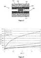
- Figure 6is a graph of heating time (s) versus temperature (°C) for each of the three configurations described above.
- Figure 6shows the maximum temperature reached after 2 s of heating.
- Curve 601is the heating curve for the configuration including a polypropylene capillary material and no porous material. The temperature reached in the capillary material after 2 s of heating is nearly 400 °C.
- Curve 603is the heating curve for the configuration including a ceramic capillary material and no porous material. The temperature reached in the capillary material after 2s of heating is less than 100 °C.
- Curve 605is the heating curve for the embodiment of the invention including a polypropylene capillary material together with a ceramic barrier. The temperature reached in the capillary material is only approximately 150 °C.
- the embodiment of the inventionhas significantly reduced the maximum temperature reached in the capillary material, whilst avoiding the need for large amounts of expensive ceramic material.
- the aerosol generating device or cartridge or systemincludes a porous material between the capillary material and the vaporizer.
- the porous materialprovides structural support to the capillary material, may reduce manufacturing costs and, if the vaporizer comprises a heater, may protect the capillary material from heat damage.
- Embodiments of the porous materialhave been described with reference to Figures 2 to 6 . Features described in relation to one embodiment may also be applicable to another embodiment.
Landscapes
- Health & Medical Sciences (AREA)
- Engineering & Computer Science (AREA)
- Animal Behavior & Ethology (AREA)
- Anesthesiology (AREA)
- Biomedical Technology (AREA)
- Heart & Thoracic Surgery (AREA)
- Hematology (AREA)
- Life Sciences & Earth Sciences (AREA)
- General Health & Medical Sciences (AREA)
- Public Health (AREA)
- Veterinary Medicine (AREA)
- Chemical & Material Sciences (AREA)
- Pulmonology (AREA)
- Bioinformatics & Cheminformatics (AREA)
- Chemical Kinetics & Catalysis (AREA)
- Ceramic Engineering (AREA)
- General Chemical & Material Sciences (AREA)
- Catching Or Destruction (AREA)
- Feeding, Discharge, Calcimining, Fusing, And Gas-Generation Devices (AREA)
- Resistance Heating (AREA)
- Investigating Or Analyzing Non-Biological Materials By The Use Of Chemical Means (AREA)
- Containers And Packaging Bodies Having A Special Means To Remove Contents (AREA)
- Medicinal Preparation (AREA)
- Sampling And Sample Adjustment (AREA)
- Disinfection, Sterilisation Or Deodorisation Of Air (AREA)
- Packaging Of Annular Or Rod-Shaped Articles, Wearing Apparel, Cassettes, Or The Like (AREA)
- Nozzles (AREA)
- Coating Apparatus (AREA)
- Measuring Or Testing Involving Enzymes Or Micro-Organisms (AREA)
- Electrostatic Spraying Apparatus (AREA)
- Physical Or Chemical Processes And Apparatus (AREA)
Description
- The present invention relates to an aerosol generating device for heating an aerosol-forming substrate. Particularly, but not exclusively, the present invention relates to an electrically operated aerosol generating device for heating a liquid aerosol-forming substrate.
WO-A-2009/132793 discloses an electrically heated smoking system. A liquid is stored in a liquid storage portion, and a capillary wick has a first end which extends into the liquid storage portion for contact with the liquid therein, and a second end which extends out of the liquid storage portion. A heating element heats the second end of the capillary wick. The heating element is in the form of a spirally wound electric heating element in electrical connection with a power supply, and surrounding the second end of the capillary wick. In use, the heating element may be activated by the user to switch on the power supply. Suction on a mouthpiece by the user causes air to be drawn into the electrically heated smoking system over the capillary wick and heating element and subsequently into the mouth of the user. A similar aerosol generating device is disclosed inEP-A-2340729 .- It is an object of the present invention to improve the generation of aerosol in an aerosol generation device or system.
- According to the invention, there is provided a cartridge comprising an aerosol-forming substrate; a vaporizer for heating the aerosol-forming substrate; a capillary material for conveying the aerosol-forming substrate towards the vaporizer by capillary action; and a porous material between the capillary material and the vaporizer. The cartridge may further comprise a storage portion for storing the aerosol-forming substrate.
- The cartridge cooperates with an aerosol-generating device to provide an aerosol generating system for vaporizing the aerosol-forming substrate. The cartridge or device may comprise the storage portion for storing the aerosol-forming substrate.
- The storage portion may be a liquid storage portion. The aerosol forming substrate may be a liquid aerosol forming substrate.
- The aerosol-forming substrate may alternatively be any other sort of substrate, for example, a gas substrate or a gel substrate, or any combination of the various types of substrate.
- The aerosol generating device or system is arranged to vaporize an aerosol-forming substrate to form the aerosol. As known to those skilled in the art, an aerosol is a suspension of solid particles or liquid droplets in a gas, such as air.
- Preferably, the capillary material is arranged to be in contact with aerosol-forming substrate in the storage portion. In one embodiment, liquid in the capillary material is vaporized by the heater to form a supersaturated vapour. The supersaturated vapour is mixed with and carried in the air flow. During the flow, the vapour condenses to form the aerosol and the aerosol is carried towards the mouth of a user. The liquid aerosol-forming substrate has suitable physical properties, including surface tension and viscosity, which allow the liquid to be transported through the capillary material by capillary action.
- The invention provides a number of advantages. First, the porous material may provide structural support for the capillary material, to prevent the capillary material from being damaged, for example, split, bent or flattened. This is particularly true if the capillary material is a flexible material and the porous material is a rigid material. If the capillary material is protected from damage, the aerosol formation is more likely to be consistent, even over multiple uses of the aerosol generating device. Second, manufacturing costs may be reduced because the capillary material may be a simple and relatively inexpensive material. The porous material may comprise a more robust and expensive material. Thus, the more expensive material need only be used for the small porous material, and the relatively inexpensive material can be used for the bulk of the device.
- The capillary material may comprise any suitable material or combination of materials which is able to convey the aerosol-forming substrate towards the vaporizer. The capillary material is preferably a porous material, but this need not be the case. The capillary material may have a fibrous or spongy structure. The capillary material preferably comprises a bundle of capillaries. For example, the capillary material may comprise a plurality of fibres or threads or other fine bore tubes. Alternatively, the capillary material may comprise sponge-like or foam-like material. The structure of the capillary material forms a plurality of small bores or tubes, through which the aerosol-forming substrate can be transported by capillary action from the storage portion towards the vaporizer. The particular preferred capillary material or materials will depend on the physical properties of the aerosol-forming substrate. Examples of suitable capillary materials include a sponge or foam material, ceramic- or graphite-based materials in the form of fibres or sintered powders, foamed metal or plastics material, a fibrous material, for example made of spun or extruded fibres, such as cellulose acetate, polyester, or bonded polyolefin, polyethylene, terylene or polypropylene fibres, nylon fibres or ceramic. The capillary material may have any suitable capillarity so as to be used with different liquid physical properties. The liquid has physical properties, including but not limited to viscosity, surface tension, density, thermal conductivity, boiling point and vapour pressure, which allow the liquid to be transported through the capillary material.
- The porous material may comprise any suitable material or combination of materials which is permeable to the aerosol-forming substrate and allows the aerosol-forming substrate to migrate from the capillary material to the vaporizer. The material or combination of materials is also inert with respect to the aerosol-forming substrate. The porous material may or may not be a capillary material. The porous material may comprise a hydrophilic material to improve distribution and spread of the aerosol-forming substrate. This may assist with consistent aerosol formation. The particular preferred material or materials will depend on the physical properties of the aerosol-forming substrate. Examples of suitable materials are a capillary material, for example a sponge or foam material, ceramic- or graphite-based materials in the form of fibres or sintered powders, a foamed metal or plastics material, a fibrous material, for example made of spun or extruded fibres, such as cellulose acetate, polyester, or bonded polyolefin, polyethylene, terylene or polypropylene fibres, nylon fibres or ceramic. The porous material may have any suitable porosity so as to be used with different liquid physical properties.
- The porous material and capillary material preferably comprise different materials. Preferably, the capillary material and the porous material are in contact, as this provides for good transfer of liquid.
- The storage portion may protect the aerosol-forming substrate from ambient air (because air cannot generally enter the liquid storage portion). The storage portion may protect the aerosol-forming substrate from light, so that the risk of degradation of the aerosol-forming substrate is significantly reduced. Moreover, a high level of hygiene can be maintained. The storage portion may not be refillable. Thus, when the aerosol-forming substrate in the storage portion has been used up, the cartridge is replaced. Alternatively, the storage portion may be refillable. In that case, the cartridge may be replaced after a certain number of refills of the storage portion. Preferably, the storage portion is arranged to hold aerosol-forming substrate for a pre-determined number of puffs.
- In a preferred embodiment, the aerosol generating device is electrically operated and the vaporizer comprises an electric heater for heating the aerosol-forming substrate.
- The electric heater may comprise a single heating element. Alternatively, the electric heater may comprise more than one heating element for example two, or three, or four, or five, or six or more heating elements. The heating element or heating elements may be arranged appropriately so as to most effectively heat the aerosol-forming substrate.
- The at least one electric heating element preferably comprises an electrically resistive material. Suitable electrically resistive materials include but are not limited to: semiconductors such as doped ceramics, electrically "conductive" ceramics (such as, for example, molybdenum disilicide), carbon, graphite, metals, metal alloys and composite materials made of a ceramic material and a metallic material. Such composite materials may comprise doped or undoped ceramics. Examples of suitable doped ceramics include doped silicon carbides. Examples of suitable metals include titanium, zirconium, tantalum and metals from the platinum group. Examples of suitable metal alloys include stainless steel, Constantan, nickel-, cobalt-, chromium-, aluminium- titanium- zirconium-, hafnium-, niobium-, molybdenum-, tantalum-, tungsten-, tin-, gallium-, manganese- and iron-containing alloys, and super-alloys based on nickel, iron, cobalt, stainless steel, Timetal®, iron-aluminium based alloys and iron-manganese-aluminium based alloys. Timetal® is a registered trade mark of Titanium Metals Corporation, 1999 Broadway Suite 4300, Denver Colorado. In composite materials, the electrically resistive material may optionally be embedded in, encapsulated or coated with an insulating material or vice-versa, depending on the kinetics of energy transfer and the external physicochemical properties required. The heating element may comprise a metallic etched foil insulated between two layers of an inert material. In that case, the inert material may comprise Kapton®, all-polyimide or mica foil. Kapton® is a registered trade mark of E.I. du Pont de Nemours and Company, 1007 Market Street, Wilmington, Delaware 19898, United States of America.
- Alternatively, the at least one electric heating element may comprise an infra-red heating element, a photonic source or an inductive heating element.
- The at least one electric heating element may take any suitable form. For example, the at least one electric heating element may take the form of a heating blade. Alternatively, the at least one electric heating element may take the form of a casing or substrate having different electroconductive portions, or an electrically resistive metallic tube. Alternatively, the at least one electric heating element may be a disk (end) heater or a combination of a disk heater with heating needles or rods. Alternatively, the at least one electric heating element may comprise a flexible sheet of material. Other alternatives include a heating wire or filament, for example a Nickel-chromium, platinum, tungsten or alloy wire, or a heating plate. Optionally, the heating element may be deposited in or on a rigid carrier material.
- The at least one electric heating element may comprise a heat sink, or heat reservoir comprising a material capable of absorbing and storing heat and subsequently releasing the heat over time to heat the aerosol-forming substrate. The heat sink may be formed of any suitable material, such as a suitable metal or ceramic material. Preferably, the material has a high heat capacity (sensible heat storage material), or is a material capable of absorbing and subsequently releasing heat via a reversible process, such as a high temperature phase change. Suitable sensible heat storage materials include silica gel, alumina, carbon, glass mat, glass fibre, minerals, a metal or alloy such as aluminium, silver or lead, and a cellulose material. Other suitable materials which release heat via a reversible phase change include paraffin, sodium acetate, naphthalene, wax, polyethylene oxide, a metal, metal salt, a mixture of eutectic salts or an alloy.
- The heat sink may be arranged such that it is directly in contact with the aerosol-forming substrate being conveyed from the storage portion and can transfer the stored heat directly to the aerosol-forming substrate. Alternatively, the heat stored in the heat sink or heat reservoir may be transferred to the aerosol-forming substrate by means of a heat conductor, such as a metallic tube.
- The at least one heating element may heat the aerosol-forming substrate by means of conduction. The heating element may be at least partially in contact with the aerosol-forming substrate. Alternatively, the heat from the heating element may be conducted to the aerosol-forming substrate by means of a heat conductor.
- Alternatively, the at least one heating element may transfer heat to the incoming ambient air that is drawn through the aerosol generating device during use, which in turn heats the aerosol-forming substrate by convection. The ambient air may be heated before passing through the aerosol-forming substrate. Alternatively, the ambient air may be first drawn through the aerosol-forming substrate and then heated.
- However, the invention is not limited to heater vaporizers but may be used in aerosol generating devices and systems in which the vapour and resulting aerosol is generated by a mechanical vaporizer, for example but not limited to a piezo vaporizer or an atomizer using pressurized liquid.
- If the vaporizer comprises an electric heater, preferably, the porous material comprises a heat-resistant material. Preferably, the electrical energy is supplied to the heating element or elements until the heating element or elements reach a temperature of between approximately 200 °C and 440 °C. This is in contrast to conventional cigarettes in which the combustion of tobacco and cigarette wrapper may reach 800 °C. Thus, the term "heat-resistant" in this specification refers to a material which is able to tolerate temperatures of more than approximately 200 °C, or more preferably more than approximately 250 °C, or even more preferably up to approximately 440 °C, without noticeably degrading. An example of a suitable material is ceramic.
- Thus, a further advantage of this embodiment of the invention is that the porous material can prevent heat damage to the capillary material. The porous material may also provide an improved, even heat distribution. This may assist with consistent aerosol formation. Suitable heat-resistant materials may be expensive. But, the capillary material only needs to tolerate the temperatures at the capillary-porous interface, because the porous material provides a heat-resistant barrier between the capillary material and the electric heater. These temperatures are lower than those at the heating element or elements. Thus, a smaller amount of potentially expensive heat-resistant material can be used. This reduces manufacturing costs. The heat-resistant material provides insulation between the heater and the capillary material.
- Preferably, the porous material comprises an electrically insulating material. If the vaporizer comprises an electric heater this prevents any short circuit of the heating elements.
- In one embodiment, the porous material simply comprises a layer of porous material between the vaporizer and the capillary material. In an alternative embodiment, the porous material comprises a coating of porous material over the vaporizer. In an alternative embodiment, the vaporizer is situated within a porous member, the porous member comprising the porous material. Thus, the vaporizer is located inside the porous member, and the portion of the porous member between the vaporizer and the capillary material forms the porous material. The vaporizer and the porous member may be integrally formed. The term "integrally formed" refers to both the vaporizer and the porous member being manufactured together in one piece.
- In a particularly preferred embodiment, the aerosol generating device is electrically operated, the vaporizer comprises an electric heater for heating the aerosol-forming substrate, and the electric heater and a porous member, including the porous material, are integrally formed. In one arrangement, the electric heater is located inside the porous member such that, when the porous member is adjacent the capillary material, the portion of the porous member between the electric heater and the capillary material forms the porous material. In that embodiment, the porous member comprises heat-resistant material.
- In one embodiment, the capillary material comprises an elongate capillary body for conveying the liquid aerosol-forming substrate from the liquid storage portion towards the vaporizer, the capillary body having a first end extending into the liquid storage portion and a second end opposite the first end, wherein the vaporizer is arranged to vaporize the liquid aerosol-forming substrate in the second end of the capillary body.
- In this embodiment, in use, liquid is transferred from the liquid storage portion by capillary action from the first end of the capillary body towards the second end of the capillary body. The porous material is provided between the second end of the capillary body and the vaporizer. Liquid in the second end of the capillary body and in the porous material is vaporized to form the supersaturated vapour. The capillary body may have the form of a wick. The capillary body may comprise fibres or threads generally aligned in the longitudinal direction of the aerosol generating device or system. Alternatively, the capillary body may comprise sponge-like or foam-like material formed into a rod shape. The rod shape may extend along the longitudinal direction of the aerosol generating device or system.
- In a preferred embodiment, the capillary material comprises an elongate capillary body for conveying the liquid aerosol-forming substrate from the liquid storage portion, the capillary body having a first end extending into the liquid storage portion and a second end opposite the first end, and the vaporizer comprises an electric heater arranged to heat the liquid aerosol-forming substrate in the second end of the capillary body. The porous material is provided between the second end of the capillary body and the electric heater. When the heater is activated, liquid at the second end of the capillary body and in the porous material is vaporized by the heater to form the supersaturated vapour.
- In one embodiment, the porous material comprises a sleeve of porous material substantially surrounding the second end of the capillary body.
- The sleeve of porous material may surround the second end of the capillary body sufficiently such that the capillary body is not in contact with the vaporizer. This is particularly important when the vaporizer comprises an electric heater, since the capillary material may not be heat-resistant. The sleeve of porous material may provide protection and support for the capillary body. The porous sleeve does not need to surround the entire capillary body, as long as the porous sleeve prevents any contact between the capillary body and the vaporizer which may damage the capillary body.
- Alternatively, or additionally, the porous material may comprise a cap of porous material substantially covering the second end of the capillary body.
- The cap of porous material may cover the second end of the capillary body sufficiently such that the capillary body is not in contact with the vaporizer. This is particularly important when the vaporizer comprises an electric heater, since the capillary material may not be heat-resistant. The cap of porous material may provide protection and support for the capillary body. For example, if the capillary body comprises a plurality of fibres or threads, the cap of porous material may reduce the likelihood of splitting or breaking of the capillary body. The porous cap does not need to cover the entire capillary body, as long as the porous cap prevents any contact between the capillary body and the vaporizer which may damage the capillary body.
- In one particularly preferred embodiment, the cartridge comprises a mouthpiece; an electric power supply and electric circuitry are arranged in the device; the capillary material comprises an elongate capillary body for conveying the aerosol-forming substrate from the liquid storage portion, the capillary body having a first end extending into the storage portion and a second end opposite the first end; the vaporizer comprises an electric heater, connectable to the electric power supply, for heating the aerosol-forming substrate in the second end of the capillary body; and the storage portion, capillary body and electric heater are arranged in the cartridge.
- The storage portion, and optionally the capillary body and the heater, may be removable from the aerosol generating system as a single component.
- In one embodiment, the storage portion includes an interior passageway, the vaporizer extends through at least part of the interior passageway in the storage portion, and the capillary material comprises a capillary interface at least partially lining the interior passageway.
- In this embodiment, in use, liquid is transferred from the liquid storage portion by capillary action through the capillary interface lining the interior passageway. The inner face of the capillary interface is preferably in contact with the liquid aerosol-forming substrate in the liquid storage portion. The porous material is provided between the outer face of the capillary interface and the vaporizer. Liquid near the outer face of the capillary interface and in the porous material is vaporized to form the supersaturated vapour. The capillary interface may comprise any suitable capillary material formed into a tube shape. The tube of capillary material may extend along all of or part of the length of the interior passageway in the liquid storage portion.
- In a preferred embodiment, the liquid storage portion has an interior passageway, the vaporizer comprises an electric heater extending through at least part of the interior passageway in the liquid storage portion and the capillary material comprises a capillary interface at least partially lining the interior passageway, wherein the electric heater is arranged to heat the liquid aerosol-forming substrate near an outer face of the capillary interface. The porous material is provided between the outer face of the capillary interface and the electric heater. When the heater is activated, the liquid near the outer face of the capillary interface is vaporized by the heater to form the supersaturated vapour.
- In that embodiment, preferably, the porous material comprises a tube of porous material inside the capillary interface, lining or partially lining the interior passageway of the liquid storage portion.
- The tube of porous material may be positioned such that the outer face of the capillary interface is not in contact with the vaporizer. This is particularly important when the vaporizer comprises an electric heater, since the capillary material of the capillary interface may not be heat-resistant. The porous material only needs to act as a barrier in the vicinity of the vaporizer.
- In one particularly preferred embodiment, the cartridge comprises a mouthpiece; an electric power supply and electric circuitry are arranged in the device; the liquid storage portion has an interior passageway; the vaporizer comprises an electric heater for heating the liquid aerosol-forming substrate, connectable to the electric power supply and extending through at least part of the interior passageway in the liquid storage portion; the capillary material comprises a capillary interface at least partially lining the interior passageway; and the liquid storage portion, capillary interface and electric heater are arranged in the cartridge.
- The liquid storage portion, and optionally the capillary interface and the heater, may be removable from the aerosol generating system as a single component.
- The liquid aerosol-forming substrate preferably has physical properties, for example boiling point and vapour pressure, suitable for use in the device, cartridge or system. If the boiling point is too high, it may not be possible to vaporize the liquid but, if the boiling point is too low, the liquid may vaporize too readily. The liquid preferably comprises a tobacco-containing material comprising volatile tobacco flavour compounds which are released from the liquid upon heating. Alternatively, or in addition, the liquid may comprise a non-tobacco material. The liquid may include aqueous solutions, non-aqueous solvents such as ethanol, plant extracts, nicotine, natural or artificial flavours or any combination of these. Preferably, the liquid further comprises an aerosol former. Examples of suitable aerosol formers are glycerine and propylene glycol.
- The aerosol generating device or cartridge may comprise at least one air inlet. The aerosol generating device or cartridge may comprise at least one air outlet. The aerosol generating device or cartridge may comprise an aerosol forming chamber between the air inlet and air outlet so as to define an air flow route from the air inlet to the air outlet via the aerosol forming chamber, so as to convey the aerosol to the air outlet and into the mouth of a user. In embodiments in which the liquid storage portion comprises an interior passageway, preferably the air flow route from the air inlet to the air outlet passes through the interior passageway. The aerosol forming chamber simply assists or facilitates the generation of the aerosol.
- The aerosol generating device may be electrically operated and may further comprise an electric power supply. The aerosol generating device may further comprise electric circuitry. In one embodiment, the electric circuitry comprises a sensor to detect air flow indicative of a user taking a puff. In that case, preferably, the electric circuitry is arranged to provide an electric current pulse to the vaporizer when the sensor senses a user taking a puff. Preferably, the time-period of the electric current pulse is pre-set, depending on the amount of liquid desired to be vaporized. The electric circuitry is preferably programmable for this purpose. Alternatively, the electric circuitry may comprise a manually operable switch for a user to initiate a puff. The time-period of the electric current pulse is preferably pre-set depending on the amount of liquid desired to be vaporized. The electric circuitry is preferably programmable for this purpose.
- Preferably, the device or cartridge or system comprises a housing. Preferably, the housing is elongate. If the aerosol generating device or cartridge includes an elongate capillary body, the longitudinal axis of the capillary body and the longitudinal axis of the housing may be substantially parallel. In one embodiment, the housing includes a removable insert comprising the liquid storage portion, the capillary body and the heater. In that embodiment, those parts may be removable from the housing as a single component. This may be useful for refilling or replacing the storage portion, for example.
- The housing may comprise any suitable material or combination of materials. Examples of suitable materials include metals, alloys, plastics or composite materials containing one or more of those materials, or thermoplastics that are suitable for food or pharmaceutical applications, for example polypropylene, polyetheretherketone (PEEK) and polyethylene. Preferably, the material is light and non-brittle.
- Preferably, the aerosol generating device and cartridge are portable, both individually and in cooperation. Preferably, the aerosol generating device is reusable by a user. Preferably, the cartridge is disposable by a user, for example when there is no more liquid contained in the liquid storage portion. The aerosol generating device and cartridge may cooperate to form an aerosol generating system which is a smoking system and which may have a size comparable to a conventional cigar or cigarette. The smoking system may have a total length between approximately 30 mm and approximately 150 mm. The smoking system may have an external diameter between approximately 5 mm and approximately 30 mm.
- Preferably, the aerosol generating system is an electrically operated smoking system.
- According to the invention, there is also provided an aerosol generating system comprising: a storage portion for storing an aerosol-forming substrate; a vaporizer for heating the aerosol-forming substrate to form an aerosol; a capillary material for conveying the aerosol-forming substrate from the storage portion towards the vaporizer by capillary action; and a porous material between the capillary material and the vaporizer. In this embodiment, the aerosol generating system does not comprise a separate device and cartridge.
- In a particularly preferred embodiment, the capillary material comprises polypropylene and the porous material comprises a ceramic material, for example, alumina (aluminium oxide).
- Features described in relation to one aspect of the invention may be applicable to another aspect of the invention.
- The invention will be further described, by way of example only, with reference to the accompanying drawings, of which:
Figure 1 shows one example of an aerosol generating systemFigure 2 is a schematic cross-sectional view of a first embodiment of a cartridge for use with an aerosol generating device to produce an aerosol generating system like that shown inFigure 1 ;Figure 3 is a schematic cross-sectional view of a second embodiment of a cartridge for use with an aerosol generating device to produce an aerosol generating system like that shown inFigure 1 ;Figure 4 is a schematic cross-sectional view of a third embodiment of a cartridge for use with an aerosol generating device to produce an aerosol generating system like that shown inFigure 1 ;Figure 5 is a schematic cross-sectional view of a fourth embodiment of a cartridge for use with an aerosol generating device to produce an aerosol generating system like that shown inFigure 1 ; andFigure 6 is a graph of heating time versus temperature for three configurations of aerosol generating system.Figure 1 shows one example of an aerosol generating system. Although not explicitly shown inFigure 1 , the aerosol generating system comprises an aerosol generating device, which is preferably reusable, in cooperation with a cartridge, which is preferably disposable. InFigure 1 , the system is an electrically operated smoking system. Thesmoking system 100 ofFigure 1 comprises ahousing 101 having a first end which is thecartridge 103 and a second end which is thedevice 105. In the device, there is provided an electric power supply in the form ofbattery 107 and electric circuitry in the form ofhardware 109 andpuff detection system 111. In the cartridge, there is provided astorage portion 113 containing liquid 115, capillary material in the form of an elongatecapillary body 117 and a vaporizer in the form ofheater 119. Note that the heater is only shown schematically inFigure 1 . In the exemplary embodiment shown inFigure 1 , one end ofcapillary body 117 extends intoliquid storage portion 113 and the other end ofcapillary body 117 is surrounded by theheater 119. The heater is connected to the electric circuitry viaconnections 121, which may pass along the outside of liquid storage portion 113 (not shown inFigure 1 ). Thehousing 101 also includes anair inlet 123, anair outlet 125 at the cartridge end, and anaerosol forming chamber 127.- In use, operation is as follows.
Liquid 115 is conveyed by capillary action from theliquid storage portion 113 from the end of thecapillary body 117 which extends into the liquid storage portion to the other end of the capillary body which is surrounded byheater 119. When a user draws on theair outlet 125, ambient air is drawn throughair inlet 123. In the arrangement shown inFigure 1 , thepuff detection system 111 senses the puff and activates theheater 119. Thebattery 107 supplies electrical energy to theheater 119 to heat the end of thecapillary body 117 surrounded by the heater. The liquid in that end of thecapillary body 117 is vaporized by theheater 119 to create a supersaturated vapour. At the same time, the liquid being vaporized is replaced by further liquid moving along thecapillary body 117 by capillary action. (This is sometimes referred to as "pumping action".) The supersaturated vapour created is mixed with and carried in the air flow from theair inlet 123. In theaerosol forming chamber 127, the vapour condenses to form an inhalable aerosol, which is carried towards theoutlet 125 and into the mouth of the user. - In the embodiment shown in
Figure 1 , thehardware 109 andpuff detection system 111 are preferably programmable. Thehardware 109 andpuff detection system 111 can be used to manage the aerosol generating operation. Figure 1 shows one example of an aerosol generating system according to the present invention. Many other examples are possible, however. The aerosol generating system simply needs to include or receive a liquid aerosol-forming substrate contained in a storage portion, a vaporizer for heating the liquid aerosol-forming substrate, a capillary material for conveying the liquid aerosol-forming substrate towards the vaporizer and some sort of porous material (to be described below with reference toFigures 2 to 6 ) between the capillary material and the vaporizer. For example, the system need not be electrically operated. For example, the system need not be a smoking system. In addition, the system may not include a heater, in which case another device may be included to vaporize the liquid aerosol-forming substrate. For example, the configuration of the capillary material may be different. For example, a puff detection system need not be provided. Instead, the system could operate by manual activation, for example the user operating a switch when a puff is taken. For example, the overall shape and size of the housing could be altered.- As discussed above, according to the invention, there is provided a porous material between the capillary material and the vaporizer. Embodiments of the invention, including the porous material, will now be described with reference to
Figures 2 to 6 . The embodiments are based on the example shown inFigure 1 , although are applicable to other embodiments. Note thatFigures 1 to 5 are schematic in nature. In particular, the components shown are not necessarily to scale either individually or relative to one another. Figure 2 is a schematic view of a first embodiment of a cartridge for use with an aerosol generating device to produce an aerosol generating system like that shown inFigure 1 . Thecartridge 200 includes astorage portion 113,capillary body 117 andheater 119. Theliquid storage portion 113 contains liquid aerosol-formingsubstrate 115. InFigure 2 , theheater 119 is in the form of a heating coil, connected to electric circuitry (not shown) viaelectrical connections 121. Theheater 119 andelectrical connections 121 are shown schematically inFigure 2 and the electrical connections may pass along the outside ofliquid storage portion 113 although this is not shown inFigure 2 . There is further provided a porous material in the form ofporous sleeve 201 surrounding the end of thecapillary body 117 which protrudes from theliquid storage portion 113.- The
porous sleeve 201 provides structural support for thecapillary body 117. Preferably, theporous sleeve 201 comprises a rigid material. Thus, theporous sleeve 201 prevents or reduces the likelihood of thecapillary body 117 becoming damaged, for example split, bent or flattened. Theporous sleeve 201 may be retained in position by slotting into the housing or another part of the aerosol generating device or cartridge, when the cartridge is assembled with the aerosol generating device. Theporous sleeve 201 preferably comprises a heat-resistant material which can protect thecapillary body 117 from potential heat damage from the heater. Thus, the porous sleeve acts as a heat barrier. Theporous sleeve 201 may also improve the heat distribution. Theporous sleeve 201 may become more efficient at liquid transfer, as the aerosol generating system heats up. InFigure 2 , the size of theporous sleeve 201 is small compared with the size of thecapillary body 117. Thus, only a small amount of heat-resistant material may be required. Since the heat-resistant material may be expensive, this may reduce manufacturing costs. In this embodiment, theporous sleeve 201 comprises an electrically insulating material so as not to cause a short circuit across the heater coils. - In
Figure 2 , theporous sleeve 201 does not cover the terminal end of thecapillary body 117. Although, inFigure 2 , theporous sleeve 201 surrounds the entire end of the capillary body which protrudes from theliquid storage portion 113, the porous sleeve may simply cover the capillary body in the vicinity of theheater 119, so as to prevent heat damage to thecapillary body 117. The required diameter of theporous sleeve 201 will depend on the size of thecapillary body 117 andliquid storage portion 113. The required length of theporous sleeve 201 will depend on the size of theheater 119 which will, in turn, depend on the amount of liquid desired to be vaporized. The required thickness of theporous sleeve 201 will depend on the insulating properties and porosity required. Figure 3 is a schematic view of a second embodiment of a cartridge for use with an aerosol generating device to produce an aerosol generating system like that shown inFigure 1 . Thecartridge 300 includes astorage portion 113,capillary body 117 andheater 119. Theliquid storage portion 113 contains liquid aerosol-formingsubstrate 115. As inFigure 2 , inFigure 3 , theheater 119 is in the form of a heating coil, connected to electric circuitry (not shown) viaelectrical connections 121. Theheater 119 andelectrical connections 121 are shown schematically inFigure 3 and the electrical connections may pass along the outside ofliquid storage portion 113 although this is not shown. There is further provided a porous material in the form ofporous cap 301 surrounding the end of thecapillary body 117 which protrudes from theliquid storage portion 113 and covering the terminal end of thecapillary body 117.- The
porous cap 301 provides structural support for thecapillary body 117. Preferably, theporous cap 301 comprises a rigid material. Thus, theporous cap 301 prevents or reduces the likelihood of thecapillary body 117 becoming damaged, for example split, bent or flattened. In particular, because the terminal end of thecapillary body 117 is covered, the chance of the capillary material splitting is substantially reduced. Theporous cap 301 may be retained in position by slotting into the housing or another part of the aerosol generating device or cartridge, when the cartridge is assembled with the aerosol generating device. Theporous cap 301 preferably comprises a heat-resistant material which can protect thecapillary body 117 from potential heat damage from the heater. Thus, the porous cap acts as a heat barrier. Theporous cap 301 may also improve the heat distribution. Theporous cap 301 may become more efficient at liquid transfer, as the aerosol generating system heats up. InFigure 3 , the size of theporous cap 301 is small compared with the size of thecapillary body 117. Thus, only a small amount of heat-resistant material may be required. Since the heat-resistant material may be expensive, this may reduce manufacturing costs. In this embodiment, theporous cap 301 comprises an electrically insulating material so as not to cause a short circuit across the heater coils. - In
Figure 3 , theporous cap 301 surrounds the entire end of the capillary body which protrudes from theliquid storage portion 113 and also covers the terminal end of thecapillary body 117. However, the porous cap may simply cover the capillary body in the vicinity of theheater 119, so as to prevent heat damage to thecapillary body 117. The required diameter of theporous cap 301 will depend on the size of thecapillary body 117 andliquid storage portion 113. The required length of theporous cap 301 will depend on the size of theheater 119 which will, in turn, depend on the amount of liquid desired to be vaporized. The required thickness of theporous cap 301 will depend on the insulating properties and porosity required. Figure 4 is a schematic view of a third embodiment of a cartridge for use with an aerosol generating device to produce an aerosol generating system like that shown inFigure 1 . Thecartridge 400 includesliquid storage portion 113 andcapillary body 117 and, as inFigures 2 and 3 , theliquid storage portion 113 contains liquid aerosol-formingsubstrate 115. There is further provided aporous member 401 surrounding the end of thecapillary body 117 which protrudes from theliquid storage portion 113. A heating blade orblades 403 are located within theporous member 401. The portion of theporous member 401 between the heater blade orblades 403 and thecapillary body 117 forms aporous material 405. Theheater blades 403 are connected to electric circuitry (not shown) viaelectrical connections 121. Theheater blades 403 andelectrical connections 121 are shown schematically inFigure 4 and the electrical connections may pass along the outside ofliquid storage portion 113 although this is not shown.- The
porous member 401 provides structural support for thecapillary body 117. Preferably, theporous member 401 comprises a rigid material. Thus, theporous member 401 prevents or reduces the likelihood of thecapillary body 117 becoming damaged, for example split, bent or flattened. Theporous member 401 may be retained in position by slotting into the housing or another part of the aerosol generating device or cartridge, when the cartridge is assembled with the aerosol generating device. Theporous member 401 preferably comprises a heat-resistant material which can protect thecapillary body 117 from potential heat damage from the heater blade orblades 403. Thus, theportion 405 of theporous member 401 between theheater blades 403 and thecapillary body 117 acts as a heat barrier. Theporous member 401 may also improve the heat distribution. Theporous member 401 may become more efficient at liquid transfer, as the aerosol generating system heats up. InFigure 4 , the size of theporous member 401 is small compared with the size of thecapillary body 117. Thus, only a small amount of heat-resistant material may be required. Since the heat-resistant material may be expensive, this may reduce manufacturing costs. In this embodiment, theporous member 401 comprises an electrically insulating material so as not to cause a short circuit across the heater blade or blades. - In
Figure 4 , theporous member 401 surrounds the entire end of the capillary body which protrudes from theliquid storage portion 113. However, theporous member 401 may be shorter than the exposed portion of the capillary body. InFigure 4 , theporous member 401 does not cover the terminal end of thecapillary body 117, although it is possible for theporous member 401 to cover the terminal end of the capillary body, like the embodiment shown inFigure 3 . Theheating blades 403 may take any form suitable for heating the liquid aerosol-forming substrate in thecapillary body 117 and theporous member 401. The required diameter of theporous member 401 will depend on the size of thecapillary body 117 andliquid storage portion 113. The required length of theporous member 401 will depend on the size and shape of the heater blades, which will, in turn, depend on the amount of liquid desired to be vaporized. The required thickness of theporous member 401, in particular theporous material 405, will depend on the insulating properties and porosity required. Preferably, theheating blades 403 and theporous member 401 are integrally formed, that is, manufactured together in one piece. This simplifies manufacture. Figure 5 is a schematic view of a fourth embodiment of a cartridge for use with an aerosol generating device to produce an aerosol generating system like that shown inFigure 1 . However, the embodiment shown inFigure 5 has a very different form from the cartridges shown inFigures 1 to 4 . InFigure 5 , thecartridge 500 comprises astorage portion 501, which is in the form of a container having aninterior passageway 503. InFigure 5 , theliquid storage portion 501 contains liquid aerosol-formingsubstrate 505. Preferably, the cartridge cooperates snugly with the aerosol generating device, and theinterior passageway 503 forms part of the air flow route for air flowing into the air inlet or inlets 123 (seeFigure 1 ) towards the air outlet 125 (seeFigure 1 ). Theinterior passageway 503 is lined or partially lined with capillary material in the form of acapillary interface 507. Aheater 509 extends through theinterior passageway 503. InFigure 5 , theheater 509 is in the form of a heating coil. The heating coil is connected to electric circuitry (not shown) via electrical connections (also not shown). There is further provided a porous material in the form ofporous tube 511 lining or partially lining theinterior passageway 503 and providing a barrier between theheater 509 and thecapillary interface 507. Preferably, theheater 509 is in contact with theporous tube 511 and preferably theporous tube 511 is in contact with thecapillary interface 507. This ensures good transfer of the liquid aerosol-forming substrate from theliquid storage portion 501 towards theheater 509.- Operation of the embodiment shown in
Figure 5 is similar to operation of the embodiments shown inFigures 1 to 4 . In use, liquid aerosol-formingsubstrate 505 is conveyed by capillary action from theliquid storage portion 501 from the side of thecapillary interface 507 in contact with the liquid to the side of thecapillary interface 507 in contact with theporous tube 511. When a user draws on the air outlet, ambient air is drawn through theinterior passageway 503 and theheater 509 is activated. Theheater 509 heats the liquid aerosol-formingsubstrate 505 in thecapillary interface 507 and in theporous tube 511, and theporous tube 511 protects thecapillary interface 507 from heat damage. The liquid is vaporized by the heater to form a supersaturated vapour and, at the same time, the liquid being vaporized is replaced by further liquid moving through thecapillary interface 507 and into theporous tube 511. The supersaturated vapour is mixed with and carried in the air flow through the interior passageway and into the mouth of the user. - The
porous tube 511 provides structural support for thecapillary interface 507. Preferably, theporous tube 511 comprises a rigid material. Thus theporous tube 511 prevents or reduces the likelihood of thecapillary interface 507 becoming damaged, for example, split or deformed. Theporous tube 511 may also help to ensure that thecapillary interface 507 stays in position lining theinterior passageway 503. Theporous tube 511 preferably comprises a heat-resistant material which can protect thecapillary interface 507 from potential heat damage from theheater 509. Thus, theporous tube 511 acts as a heat barrier. Theporous tube 511 may also improve the heat distribution. Theporous tube 511 may become more efficient at liquid transfer, as the aerosol generating system heats up. InFigure 5 , the length of theporous tube 511 is small compared with the length of thecapillary interface 507. Thus, only a small amount of heat-resistant material may be required. Since the heat-resistant material may be expensive, this may reduce manufacturing costs. In this embodiment, theporous tube 511 may comprise an electrically insulating material so as not to cause a short circuit across the heater coils. - In
Figure 5 , theporous tube 511 does not extend along the length of theliquid storage portion 501 andcapillary interface 507, although this is possible. Theporous tube 511 may extend along any length of theliquid storage portion 501 andcapillary interface 507 as long as it provides a barrier for thecapillary interface 507 in the vicinity of theheater 509. The required diameter of theporous tube 511 will depend on the size of theinterior passageway 503 of theliquid storage portion 501. The required length of theporous tube 511 will depend on the size of theheater 509 which will, in turn, depend on the amount of liquid desired to be vaporized. The required thickness of theporous tube 511 will depend on the insulating properties and porosity required. - The embodiments illustrated in
Figures 2 to 5 include a capillary material and a porous material. The capillary material may comprise any suitable material or combination of materials which is able to convey the liquid aerosol-forming substrate towards the heater. Examples of suitable capillary materials include a sponge or foam material, ceramic- or graphite-based materials in the form of fibres or sintered powders, foamed metal or plastics material, a fibrous material, for example made of spun or extruded fibres, such as cellulose acetate, polyester, or bonded polyolefin, polyethylene, terylene or polypropylene fibres, nylon fibres or ceramic. The capillary material may have any suitable capillarity so as to be used with different liquid physical properties. - The porous material may comprise any suitable material or combination of materials which is permeable to the liquid aerosol-forming substrate and allows the liquid aerosol-forming substrate to migrate from the capillary material to the heater. The porous material may comprise a material which is inherently porous, for example a ceramic material such as alumina (aluminium oxide). Alternatively, the porous material may comprise a material with a plurality of manufactured small holes, to allow migration of the liquid aerosol-forming substrate to the vaporizer. The porous material may comprise a hydrophilic material to improve distribution and spread of the liquid aerosol-forming substrate. The particular preferred material or materials will depend on the physical properties of the liquid aerosol-forming substrate. Examples of suitable materials are a capillary material, for example a sponge or foam material, ceramic- or graphite-based materials in the form of fibres or sintered powders, a foamed metal or plastics material, a fibrous material, for example made of spun or extruded fibres, such as cellulose acetate, polyester, or bonded polyolefin, polyethylene, terylene or polypropylene fibres, nylon fibres or ceramic. The porous material may have any suitable porosity so as to be used with different liquid physical properties. In the embodiments illustrated in
Figures 2 to 5 , the porous material is a separate component. However, other forms for the porous material may be envisaged. For example, the porous material may comprise a porous coating over the heater or part of the heater. Other embodiments are also possible. Figures 2 to 5 show examples of cartridges for use with an aerosol generating device according to the present invention. Other examples are possible. Preferably, the cartridge is disposable and is arranged to cooperate with an aerosol generating device which may be reusable. The cartridge may be refilled or replaced when the liquid is used. Thus, when the liquid aerosol-forming substrate in the cartridge has been used up, the cartridge may be disposed of and replaced with a new cartridge, or the empty cartridge may be refilled. However, the aerosol generating device may not be designed to operate in conjunction with a separate cartridge. Instead, the aerosol generating device may include or receive a liquid aerosol-forming substrate in a storage portion and comprise the vaporizer for heating the liquid aerosol-forming substrate, the capillary material for conveying the liquid aerosol-forming substrate towards the vaporizer and the porous material between the vaporizer and the capillary material. That is to say, the aerosol generating device may comprise all the components described in relation to the cartridge. Additionally, the aerosol generating device may comprise an electric power supply and electric circuitry.- In
Figures 1 to 5 , the vaporizer comprises an electric heater and the porous material protects the capillary material from heat damage. The porous material also improves heat distribution which results in more consistent aerosol formation. In one preferred embodiment, the capillary material comprises polypropylene and the porous material comprises ceramic. The inventors of the present invention have compared the heat distribution patterns across the polypropylene capillary material and ceramic barrier with the heat distribution patterns in arrangements without a porous material. If the capillary material is polypropylene, and no porous material is provided, it has been found that, after only 2 s of heating, the temperatures in the capillary material exceed the melting temperature of polypropylene. The temperatures are not homogeneous, with steep temperature gradients and hot spots. Thus, even though polypropylene would be a convenient (and relatively inexpensive) material to use for the capillary material, it cannot be used (without a porous material) since the polypropylene would melt. On the other hand, if the capillary material is ceramic, and no porous material is provided, it has been found that, after only 2 s of heating, the temperatures in the capillary material do not exceed the melting temperature of the ceramic (which is much higher than that of polypropylene). Thus, ceramic would be an ideal material for the capillary material, but it is relatively expensive. According to one embodiment of the invention, the capillary material comprises polypropylene, and a ceramic porous material is provided. In that embodiment, it has been found that the temperature in the polypropylene capillary material is considerably lower than that found with a polypropylene capillary material alone, because the ceramic barrier protects the capillary material. The temperatures have also been found to be reasonably homogeneous. Thus, the bulk of the required material can be the (relatively inexpensive) polypropylene, but the polypropylene can be protected from temperatures above its melting point by the ceramic barrier. Figure 6 is a graph of heating time (s) versus temperature (°C) for each of the three configurations described above.Figure 6 shows the maximum temperature reached after 2 s of heating.Curve 601 is the heating curve for the configuration including a polypropylene capillary material and no porous material. The temperature reached in the capillary material after 2 s of heating is nearly 400 °C. Curve 603 is the heating curve for the configuration including a ceramic capillary material and no porous material. The temperature reached in the capillary material after 2s of heating is less than 100 °C. Curve 605 is the heating curve for the embodiment of the invention including a polypropylene capillary material together with a ceramic barrier. The temperature reached in the capillary material is only approximately 150 °C. Thus, the embodiment of the invention has significantly reduced the maximum temperature reached in the capillary material, whilst avoiding the need for large amounts of expensive ceramic material.- Thus, according to the invention, the aerosol generating device or cartridge or system includes a porous material between the capillary material and the vaporizer. The porous material provides structural support to the capillary material, may reduce manufacturing costs and, if the vaporizer comprises a heater, may protect the capillary material from heat damage. Embodiments of the porous material have been described with reference to
Figures 2 to 6 . Features described in relation to one embodiment may also be applicable to another embodiment.
Claims (8)
- A cartridge (200) comprising:an aerosol-forming substrate (115);a vaporizer for heating the aerosol-forming substrate (115);a capillary material for conveying the aerosol-forming substrate (115) towards the vaporizer by capillary action; andcharacterized by a porous material between the capillary material and the vaporizer.
- A cartridge (200) according to claim 1, wherein the vaporizer comprises an electric heater (119) for heating the aerosol-forming substrate (115), the electric heater (119) being connectable to an electric power supply in an aerosol generating device (105).
- A cartridge (200) according to claim 1 or 2, wherein the porous material comprises a heat-resistant material.
- A cartridge (200) according to claim 3, wherein the heat-resistant material comprises a ceramic.
- A cartridge (200) according to any of claims 1 to 4, further comprising a storage portion (113) for storing the aerosol-forming substrate (115).
- A cartridge (200) according to claim 5, wherein the capillary material comprises an elongate capillary body (117) for conveying the aerosol-forming substrate (115) from the storage portion (113) towards the vaporizer, the capillary body (117) having a first end extending into the storage portion (113) and a second end opposite the first end, wherein the vaporizer is arranged to vaporize the aerosol-forming substrate (115) in the second end of the capillary body.
- A cartridge (200) according to claim 5, wherein the storage portion (113) includes an interior passageway, the vaporizer extends through at least part of the interior passageway in the storage portion (113), and the capillary material comprises a capillary interface at least partially lining the interior passageway.
- An aerosol generating system (100) comprising an aerosol generating device (105) in cooperation with a cartridge (200) according to any of claims 1 to 7.
Priority Applications (8)
| Application Number | Priority Date | Filing Date | Title |
|---|---|---|---|
| EP20194909.6AEP3763407A1 (en) | 2011-12-08 | 2012-12-05 | An aerosol generating device with a capillary interface |
| SI201231284TSI3072407T1 (en) | 2011-12-08 | 2012-12-05 | An aerosol-generating device with a capillary interface |
| NO16165974ANO3072407T3 (en) | 2011-12-08 | 2012-12-05 | |
| PL18161610TPL3357357T3 (en) | 2011-12-08 | 2012-12-05 | An aerosol generating device with a capillary interface |
| PL16165974TPL3072407T3 (en) | 2011-12-08 | 2012-12-05 | An aerosol-generating device with a capillary interface |
| EP16165974.3AEP3072407B1 (en) | 2011-12-08 | 2012-12-05 | An aerosol-generating device with a capillary interface |
| RS20180548ARS57204B1 (en) | 2011-12-08 | 2012-12-05 | An aerosol-generating device with a capillary interface |
| EP18161610.3AEP3357357B1 (en) | 2011-12-08 | 2012-12-05 | An aerosol generating device with a capillary interface |
Applications Claiming Priority (3)
| Application Number | Priority Date | Filing Date | Title |
|---|---|---|---|
| EP11192697 | 2011-12-08 | ||
| EP12815654.4AEP2787847B1 (en) | 2011-12-08 | 2012-12-05 | An aerosol generating device with a capillary interface |
| EP16165974.3AEP3072407B1 (en) | 2011-12-08 | 2012-12-05 | An aerosol-generating device with a capillary interface |
Related Parent Applications (1)
| Application Number | Title | Priority Date | Filing Date |
|---|---|---|---|
| EP12815654.4ADivisionEP2787847B1 (en) | 2011-12-08 | 2012-12-05 | An aerosol generating device with a capillary interface |
Related Child Applications (2)
| Application Number | Title | Priority Date | Filing Date |
|---|---|---|---|
| EP18161610.3ADivisionEP3357357B1 (en) | 2011-12-08 | 2012-12-05 | An aerosol generating device with a capillary interface |
| EP20194909.6ADivisionEP3763407A1 (en) | 2011-12-08 | 2012-12-05 | An aerosol generating device with a capillary interface |
Publications (2)
| Publication Number | Publication Date |
|---|---|
| EP3072407A1 EP3072407A1 (en) | 2016-09-28 |
| EP3072407B1true EP3072407B1 (en) | 2018-04-11 |
Family
ID=47559385
Family Applications (4)
| Application Number | Title | Priority Date | Filing Date |
|---|---|---|---|
| EP16165974.3AActiveEP3072407B1 (en) | 2011-12-08 | 2012-12-05 | An aerosol-generating device with a capillary interface |
| EP12815654.4AActiveEP2787847B1 (en) | 2011-12-08 | 2012-12-05 | An aerosol generating device with a capillary interface |
| EP20194909.6APendingEP3763407A1 (en) | 2011-12-08 | 2012-12-05 | An aerosol generating device with a capillary interface |
| EP18161610.3AActiveEP3357357B1 (en) | 2011-12-08 | 2012-12-05 | An aerosol generating device with a capillary interface |
Family Applications After (3)
| Application Number | Title | Priority Date | Filing Date |
|---|---|---|---|
| EP12815654.4AActiveEP2787847B1 (en) | 2011-12-08 | 2012-12-05 | An aerosol generating device with a capillary interface |
| EP20194909.6APendingEP3763407A1 (en) | 2011-12-08 | 2012-12-05 | An aerosol generating device with a capillary interface |
| EP18161610.3AActiveEP3357357B1 (en) | 2011-12-08 | 2012-12-05 | An aerosol generating device with a capillary interface |
Country Status (28)
| Country | Link |
|---|---|
| US (2) | US9364800B2 (en) |
| EP (4) | EP3072407B1 (en) |
| JP (4) | JP6038948B2 (en) |
| KR (2) | KR102148142B1 (en) |
| CN (2) | CN106213585B (en) |
| AR (2) | AR089588A1 (en) |
| AU (2) | AU2012347290B2 (en) |
| BR (1) | BR112014013755B1 (en) |
| CA (1) | CA2857989C (en) |
| DK (2) | DK2787847T3 (en) |
| ES (2) | ES2831033T3 (en) |
| HU (3) | HUE051765T2 (en) |
| IL (1) | IL232792B (en) |
| LT (1) | LT3072407T (en) |
| MX (1) | MX345610B (en) |
| MY (1) | MY177798A (en) |
| NO (1) | NO3072407T3 (en) |
| PH (1) | PH12014501189B1 (en) |
| PL (3) | PL2787847T3 (en) |
| PT (1) | PT3072407T (en) |
| RS (2) | RS57204B1 (en) |
| RU (2) | RU2615960C2 (en) |
| SG (1) | SG11201402916TA (en) |
| SI (1) | SI3072407T1 (en) |
| TW (1) | TWI595839B (en) |
| UA (1) | UA112883C2 (en) |
| WO (1) | WO2013083634A1 (en) |
| ZA (1) | ZA201403918B (en) |
Families Citing this family (166)
| Publication number | Priority date | Publication date | Assignee | Title |
|---|---|---|---|---|
| US20160345631A1 (en) | 2005-07-19 | 2016-12-01 | James Monsees | Portable devices for generating an inhalable vapor |
| CN103491815B (en) | 2011-02-11 | 2016-01-20 | 巴特马克有限公司 | Inhalator assembly |
| US20140202476A1 (en) | 2011-09-06 | 2014-07-24 | British American Tobacco (Investments) Limited | Heating smokeable material |
| UA112883C2 (en)* | 2011-12-08 | 2016-11-10 | Філіп Морріс Продактс С.А. | DEVICE FOR THE FORMATION OF AEROSOL WITH A CAPILLARY BORDER LAYER |
| EP2807935A4 (en)* | 2012-01-25 | 2015-11-11 | Fontem Holdings 1 Bv | ELECTRONIC CIGARETTE AND ITS ATOMIZER |
| GB2504076A (en) | 2012-07-16 | 2014-01-22 | Nicoventures Holdings Ltd | Electronic smoking device |
| GB2504075A (en)* | 2012-07-16 | 2014-01-22 | Nicoventures Holdings Ltd | Electronic smoking device |
| GB201217067D0 (en) | 2012-09-25 | 2012-11-07 | British American Tobacco Co | Heating smokable material |
| US10034988B2 (en) | 2012-11-28 | 2018-07-31 | Fontem Holdings I B.V. | Methods and devices for compound delivery |
| US9877508B2 (en)* | 2013-03-15 | 2018-01-30 | Altria Client Services Llc | Electronic cigarette |
| US10279934B2 (en) | 2013-03-15 | 2019-05-07 | Juul Labs, Inc. | Fillable vaporizer cartridge and method of filling |
| CA2907731A1 (en) | 2013-03-22 | 2014-09-25 | Altria Client Services Llc | Electronic smoking article |
| US10194693B2 (en) | 2013-09-20 | 2019-02-05 | Fontem Holdings 1 B.V. | Aerosol generating device |
| US9962673B2 (en) | 2013-10-29 | 2018-05-08 | Palo Alto Research Center Incorporated | Methods and systems for creating aerosols |
| US10016777B2 (en)* | 2013-10-29 | 2018-07-10 | Palo Alto Research Center Incorporated | Methods and systems for creating aerosols |
| US10039321B2 (en) | 2013-11-12 | 2018-08-07 | Vmr Products Llc | Vaporizer |
| WO2015077645A1 (en)* | 2013-11-21 | 2015-05-28 | Corr-Tech Associates, Inc. | Improved vaporization and dosage control for electronic vaporizing inhaler |
| USD825102S1 (en) | 2016-07-28 | 2018-08-07 | Juul Labs, Inc. | Vaporizer device with cartridge |
| DE202014011260U1 (en) | 2013-12-23 | 2018-11-13 | Juul Labs Uk Holdco Limited | Systems for an evaporation device |
| US10159282B2 (en) | 2013-12-23 | 2018-12-25 | Juul Labs, Inc. | Cartridge for use with a vaporizer device |
| USD842536S1 (en) | 2016-07-28 | 2019-03-05 | Juul Labs, Inc. | Vaporizer cartridge |
| US10058129B2 (en) | 2013-12-23 | 2018-08-28 | Juul Labs, Inc. | Vaporization device systems and methods |
| US10076139B2 (en) | 2013-12-23 | 2018-09-18 | Juul Labs, Inc. | Vaporizer apparatus |
| US20160366947A1 (en) | 2013-12-23 | 2016-12-22 | James Monsees | Vaporizer apparatus |
| US9974334B2 (en) | 2014-01-17 | 2018-05-22 | Rai Strategic Holdings, Inc. | Electronic smoking article with improved storage of aerosol precursor compositions |
| TWM478798U (en)* | 2014-01-28 | 2014-05-21 | Wei-Li Tsai | Smoke blowing device |
| TWI761216B (en) | 2014-02-06 | 2022-04-11 | 美商尤爾實驗室有限公司 | A device for generating an inhalable aerosol and a separable cartridge for use therewith |
| US12279646B2 (en) | 2014-02-06 | 2025-04-22 | Juul Labs, Inc. | Cartridge of vaporization device systems having unequal transverse cartridge dimensions |
| US10709173B2 (en) | 2014-02-06 | 2020-07-14 | Juul Labs, Inc. | Vaporizer apparatus |
| MY176431A (en)* | 2014-02-10 | 2020-08-07 | Philip Morris Products Sa | Cartridge for an aerosol-generating system |
| KR102515717B1 (en)* | 2014-02-10 | 2023-03-30 | 필립모리스 프로덕츠 에스.에이. | An aerosol-generating system having a fluid-permeable heater assembly |
| AU2014381789B2 (en)* | 2014-02-10 | 2019-03-14 | Philip Morris Products S.A. | Cartridge for an aerosol-generating system |
| KR20240042543A (en) | 2014-02-10 | 2024-04-02 | 필립모리스 프로덕츠 에스.에이. | An aerosol-generating system having a fluid-permeable heater assembly |
| KR20230167768A (en) | 2014-02-10 | 2023-12-11 | 필립모리스 프로덕츠 에스.에이. | Cartridge with a heater assembly for an aerosol-generating system |
| BR112016015685A8 (en) | 2014-02-10 | 2020-06-09 | Philip Morris Products Sa | fluid permeable heater assembly for an aerosol generating system and method for assembling a fluid permeable heater for an aerosol generating system, and aerosol generating system |
| CN203828084U (en)* | 2014-03-18 | 2014-09-17 | 刘秋明 | Electronic cigarette |
| GB201407056D0 (en) | 2014-04-22 | 2014-06-04 | Essentra Filter Products Dev Co Pte Ltd | Smoking article |
| CA2985988C (en)* | 2014-05-12 | 2021-05-25 | Loto Labs, Inc. | Improved vaporizer device |
| TWI660685B (en) | 2014-05-21 | 2019-06-01 | 瑞士商菲利浦莫里斯製品股份有限公司 | Electrothermal aerosol generating system and cylinder used in the system |
| WO2015180018A1 (en)* | 2014-05-26 | 2015-12-03 | 深圳麦克韦尔股份有限公司 | Electronic cigarette |
| GB201411483D0 (en)* | 2014-06-27 | 2014-08-13 | Batmark Ltd | Vaporizer Assembly |
| CN204070557U (en)* | 2014-07-31 | 2015-01-07 | 深圳市合元科技有限公司 | Atomization core and electrical smoking device |
| WO2016050246A1 (en)* | 2014-10-03 | 2016-04-07 | Fertin Pharma A/S | Electronic nicotine delivery system |
| GB2546934B (en)* | 2014-11-11 | 2018-04-11 | Jt Int Sa | Electronic vapour inhalers |
| BR112017010106A2 (en) | 2014-11-17 | 2018-01-02 | Mcneil Ab | disposable cartridge for use in an electronic nicotine release system |
| US10188148B2 (en) | 2014-11-17 | 2019-01-29 | Mcneil Ab | Electronic nicotine delivery system |
| WO2016090037A1 (en)* | 2014-12-02 | 2016-06-09 | Goldstein Gabriel Marc | Vaporizing reservoir |
| MX394125B (en) | 2014-12-05 | 2025-03-24 | Juul Labs Inc | CALIBRATED DOSE CONTROL |
| WO2016091658A1 (en)* | 2014-12-11 | 2016-06-16 | Philip Morris Products S.A. | Inhaling device with user recognition based on inhalation behaviour |
| CN204426707U (en) | 2014-12-12 | 2015-07-01 | 卓尔悦(常州)电子科技有限公司 | Atomising device and the electronic cigarette containing this atomising device |
| CN107846972B (en) | 2014-12-31 | 2020-09-15 | 尤特维吉环球爱普公司 | Personal electronic delivery system, atomizer assembly, use thereof and corresponding production method |
| WO2016108694A1 (en)* | 2014-12-31 | 2016-07-07 | UTVG Global IP B.V. | Personal electronic delivery system, atomizer assembly, use thereof and corresponding production method |
| NL2014461B1 (en)* | 2014-12-31 | 2016-10-12 | Utvg Global Ip B V | Personal electronic delivery system and method for delivering a delivery fluid. |
| US20210172650A1 (en)* | 2015-02-05 | 2021-06-10 | Giorgio TORCHIO | Capillary Proximity Heater |
| JP6691547B2 (en)* | 2015-02-05 | 2020-04-28 | トルキーノ,ジョルジョ | A fluid heating device characterized by high energy saving and provided with a microfiltration device for removing lime particles remaining in a fluid and a nozzle or a closed circuit |
| CN104770878B (en)* | 2015-03-23 | 2017-11-24 | 云南中烟工业有限责任公司 | A kind of electric heating type cigarette smoking device with electronic cigarette pumping function |
| GB201505597D0 (en) | 2015-03-31 | 2015-05-13 | British American Tobacco Co | Article for use with apparatus for heating smokable material |
| GB201505595D0 (en) | 2015-03-31 | 2015-05-13 | British American Tobacco Co | Cartridge for use with apparatus for heating smokeable material |
| RU2698550C2 (en)* | 2015-04-30 | 2019-08-28 | Филип Моррис Продактс С.А. | Cartridge for aerosol generating system |
| WO2016194076A1 (en) | 2015-05-29 | 2016-12-08 | 日本たばこ産業株式会社 | Non-combustion flavor inhaler |
| EP3315035B1 (en)* | 2015-06-26 | 2019-12-25 | Japan Tobacco Inc. | Atomizing unit |
| GB201511358D0 (en) | 2015-06-29 | 2015-08-12 | Nicoventures Holdings Ltd | Electronic aerosol provision systems |
| GB201511349D0 (en) | 2015-06-29 | 2015-08-12 | Nicoventures Holdings Ltd | Electronic aerosol provision systems |
| GB201511359D0 (en) | 2015-06-29 | 2015-08-12 | Nicoventures Holdings Ltd | Electronic vapour provision system |
| GB201511361D0 (en)* | 2015-06-29 | 2015-08-12 | Nicoventures Holdings Ltd | Electronic vapour provision system |
| FR3039041B1 (en)* | 2015-07-20 | 2018-07-13 | Innovi | ARRANGEMENT OF AN E-CIGARETTE WITH THE CONTENTS OF THE RESERVOIR PRESERVE OF HEAT |
| KR102659808B1 (en) | 2015-08-07 | 2024-04-23 | 필립모리스 프로덕츠 에스.에이. | Aerosol generation system with enhanced airflow management |
| MX2018001418A (en) | 2015-08-07 | 2018-04-13 | Philip Morris Products Sa | An aerosol-generating system with enhanced airflow management. |
| GB2541719B (en)* | 2015-08-27 | 2019-06-12 | Nerudia Ltd | An inhaler |
| US20170055584A1 (en) | 2015-08-31 | 2017-03-02 | British American Tobacco (Investments) Limited | Article for use with apparatus for heating smokable material |
| US11924930B2 (en) | 2015-08-31 | 2024-03-05 | Nicoventures Trading Limited | Article for use with apparatus for heating smokable material |
| US20170055575A1 (en) | 2015-08-31 | 2017-03-02 | British American Tobacco (Investments) Limited | Material for use with apparatus for heating smokable material |
| GB2542838B (en) | 2015-10-01 | 2022-01-12 | Nicoventures Trading Ltd | Aerosol provision system |
| US11006667B2 (en) | 2015-10-16 | 2021-05-18 | 14Th Round Inc. | Assembly for providing chemicals for smokeless administration, a disposable tank, and a method of using the same |
| US20170119046A1 (en) | 2015-10-30 | 2017-05-04 | British American Tobacco (Investments) Limited | Apparatus for Heating Smokable Material |
| US20170119047A1 (en) | 2015-10-30 | 2017-05-04 | British American Tobacco (Investments) Limited | Article for Use with Apparatus for Heating Smokable Material |
| CO2018009342A2 (en) | 2016-02-11 | 2018-09-20 | Juul Labs Inc | Secure fixing cartridges for vaporizing devices |
| EP3413960B1 (en) | 2016-02-11 | 2021-03-31 | Juul Labs, Inc. | Fillable vaporizer cartridge and method of filling |
| UA126061C2 (en) | 2016-02-25 | 2022-08-10 | Джуул Лебз, Інк. | SYSTEMS AND METHODS OF CONTROLLING THE EVAPORATION DEVICE |
| US10405582B2 (en) | 2016-03-10 | 2019-09-10 | Pax Labs, Inc. | Vaporization device with lip sensing |
| CN205624467U (en)* | 2016-03-21 | 2016-10-12 | 深圳市合元科技有限公司 | Tobacco tar heating element reaches electron cigarette and atomizer including this tobacco tar heating element |
| US10321712B2 (en)* | 2016-03-29 | 2019-06-18 | Altria Client Services Llc | Electronic vaping device |
| US10334882B2 (en)* | 2016-04-13 | 2019-07-02 | Md&C Creative Masion Sa | Electronic cigarette |
| CN105747278A (en)* | 2016-04-21 | 2016-07-13 | 深圳市合元科技有限公司 | Cigarette liquid heating device, atomizing unit, atomizer and electronic cigarette |
| WO2017185051A1 (en) | 2016-04-22 | 2017-10-26 | Pax Labs, Inc. | Aerosol devices having compartmentalized materials |
| ES2987583T3 (en) | 2016-04-27 | 2024-11-15 | Nicoventures Trading Ltd | Electronic aerosol supply system and aerosol vaporizer |
| CA3014497A1 (en)* | 2016-05-31 | 2017-12-07 | Philip Morris Products S.A. | Heater and wick assembly for an aerosol generating system |
| USD849996S1 (en) | 2016-06-16 | 2019-05-28 | Pax Labs, Inc. | Vaporizer cartridge |
| GB2552298B (en)* | 2016-06-17 | 2020-11-04 | Sata Ltd | Stimulus generating apparatus |
| JP2019522965A (en)* | 2016-06-20 | 2019-08-22 | フィリップ・モーリス・プロダクツ・ソシエテ・アノニム | Vaporizer assembly for aerosol generation system |
| USD836541S1 (en) | 2016-06-23 | 2018-12-25 | Pax Labs, Inc. | Charging device |
| USD851830S1 (en) | 2016-06-23 | 2019-06-18 | Pax Labs, Inc. | Combined vaporizer tamp and pick tool |
| USD848057S1 (en) | 2016-06-23 | 2019-05-07 | Pax Labs, Inc. | Lid for a vaporizer |
| US10463077B2 (en) | 2016-06-24 | 2019-11-05 | Altria Client Services Llc | Cartridge for e-vaping device with open-microchannels |
| US10292426B2 (en)* | 2016-06-24 | 2019-05-21 | Altria Client Services, Llc | E-vaping device cartridge with superabsorbent polymer |
| ES2649030B1 (en)* | 2016-07-08 | 2018-11-02 | Zobele España, S.A. | Evaporation device for volatile substances |
| US10729177B2 (en)* | 2016-07-31 | 2020-08-04 | Altria Client Services Llc | Electronic vaping device, battery section, and charger |
| US11903099B2 (en)* | 2016-08-12 | 2024-02-13 | Altria Client Services Llc | Vaporizer of an electronic vaping device and method of forming a vaporizer |
| US11937647B2 (en) | 2016-09-09 | 2024-03-26 | Rai Strategic Holdings, Inc. | Fluidic control for an aerosol delivery device |
| JP7121746B2 (en) | 2016-12-19 | 2022-08-18 | フィリップ・モーリス・プロダクツ・ソシエテ・アノニム | Aerosol generating system with external cartridge |
| KR102593862B1 (en)* | 2016-12-27 | 2023-10-24 | 쥴 랩스, 인크. | Thermal Wick for Electronic Vaporizers |
| US10834967B2 (en)* | 2016-12-27 | 2020-11-17 | Gofire, Inc. | System and method for managing concentrate usage of a user |
| GB201703284D0 (en) | 2017-03-01 | 2017-04-12 | Nicoventures Holdings Ltd | Vapour provision device with liquid capture |
| US10226074B2 (en)* | 2017-03-02 | 2019-03-12 | Vitali Servutas | Electronic cigarette and electronic cigarette cartridge |
| US10314340B2 (en)* | 2017-04-21 | 2019-06-11 | Rai Strategic Holdings, Inc. | Refillable aerosol delivery device and related method |
| GB2561867B (en)* | 2017-04-25 | 2021-04-07 | Nerudia Ltd | Aerosol delivery system |
| CN109259328A (en)* | 2017-07-17 | 2019-01-25 | 上海新型烟草制品研究院有限公司 | A kind of capillary drain atomizer and electronic cigarette device |
| CN109259329A (en)* | 2017-07-17 | 2019-01-25 | 上海新型烟草制品研究院有限公司 | A kind of atomizer and electronic cigarette device with lead rod structure |
| CN109259323B (en)* | 2017-07-17 | 2024-05-28 | 上海新型烟草制品研究院有限公司 | Atomizer and electronic cigarette |
| CN109259322A (en)* | 2017-07-17 | 2019-01-25 | 上海新型烟草制品研究院有限公司 | Atomising device, method and electronic smoke atomizer |
| CN109259321B (en)* | 2017-07-17 | 2024-06-25 | 上海新型烟草制品研究院有限公司 | Atomization component, atomizer and electronic cigarette |
| CN109259325B (en)* | 2017-07-17 | 2024-05-28 | 上海新型烟草制品研究院有限公司 | Electronic cigarette atomizer |
| USD887632S1 (en) | 2017-09-14 | 2020-06-16 | Pax Labs, Inc. | Vaporizer cartridge |
| DK3749121T3 (en)* | 2018-02-06 | 2022-03-21 | Mcneil Ab | CARTRIDGE FOR ELECTRONIC DELIVERY SYSTEM |
| JP7485614B2 (en)* | 2018-06-06 | 2024-05-16 | フィリップ・モーリス・プロダクツ・ソシエテ・アノニム | Aerosol generating device having a movable component for moving an aerosol-forming substrate - Patent Application 20070123633 |
| WO2019237052A1 (en)* | 2018-06-07 | 2019-12-12 | Juul Labs, Inc. | Cartridges for vaporizer devices |
| US10986875B2 (en) | 2018-06-25 | 2021-04-27 | Juul Labs, Inc. | Vaporizer device heater control |
| EP3813914B1 (en)* | 2018-06-26 | 2023-10-25 | Juul Labs, Inc. | Vaporizer wicking elements |
| CN119632302A (en) | 2018-07-31 | 2025-03-18 | 尤尔实验室有限公司 | Cartridge-based heat-without-burn vaporizer |
| US11413409B2 (en) | 2018-09-12 | 2022-08-16 | Juul Labs, Inc. | Vaporizer including positive temperature coefficient of resistivity (PTCR) heating element |
| US11930845B2 (en)* | 2018-10-03 | 2024-03-19 | Philip Morris Products S.A. | Liquid supply system for use in aerosol-generating devices |
| KR20250048483A (en) | 2018-10-08 | 2025-04-08 | 쥴 랩스, 인크. | Heating element |
| CA3118713A1 (en) | 2018-11-05 | 2020-05-14 | Juul Labs, Inc. | Cartridges for vaporizer devices |
| EP4537877A3 (en)* | 2018-11-05 | 2025-06-04 | Juul Labs, Inc. | Cartridges for vaporizer devices |
| JP7502015B2 (en) | 2018-11-08 | 2024-06-18 | ジュール・ラブズ・インコーポレイテッド | Vaporizer device with one or more heating elements |
| US11553734B2 (en) | 2018-11-08 | 2023-01-17 | Juul Labs, Inc. | Cartridges for vaporizer devices |
| GB201818270D0 (en)* | 2018-11-09 | 2018-12-26 | Nicoventures Trading Ltd | Component for a vapour provision system |
| WO2020154690A1 (en) | 2019-01-25 | 2020-07-30 | Juul Labs, Inc. | Vaporizer device and cartridge |
| MX2021009073A (en) | 2019-01-31 | 2021-09-10 | Dynavap Llc | INDIRECT EXOTHERMIC VAPORIZATION MATRIX. |
| US10688793B1 (en) | 2019-02-26 | 2020-06-23 | Funai Electric Co., Ltd. | Fluidic dispensing apparatus and fluid dispensing cartridge therefor |
| US11369781B2 (en) | 2019-02-26 | 2022-06-28 | Funai Electric Co., Ltd. | Fluidic dispensing apparatus and associated fluid dispensing cartridge |
| EP3711607A1 (en)* | 2019-03-21 | 2020-09-23 | Nerudia Limited | Aerosol delivery system |
| CA3138711A1 (en)* | 2019-05-06 | 2020-11-12 | Juul Labs, Inc. | Insert for use with vaporizer device |
| US12082611B2 (en) | 2019-05-24 | 2024-09-10 | Imperial Tobacco Limited | Aerosol delivery device |
| EP3741413A1 (en)* | 2019-05-24 | 2020-11-25 | Nerudia Limited | Refill device for aerosol delivery device |
| PL3979858T3 (en)* | 2019-06-07 | 2024-01-22 | Jt International S.A. | Aerosol generation device with tilted heating chamber |
| EP3983035B1 (en) | 2019-06-12 | 2025-05-28 | Juul Labs, Inc. | Vaporizable material insert for vaporizer device |
| GB201910509D0 (en) | 2019-07-23 | 2019-09-04 | Nicoventures Holdings Ltd | Porpus element for a vapour provision system |
| JP7614175B2 (en) | 2019-08-08 | 2025-01-15 | ジュール・ラブズ・インコーポレイテッド | Vaporizable material insert for vaporizer device |
| EP3795008A1 (en)* | 2019-09-20 | 2021-03-24 | Nerudia Limited | Smoking substitute apparatus |
| JP7645032B2 (en)* | 2019-11-18 | 2025-03-13 | 東京エレクトロン株式会社 | Streamlined Carburetor Core |
| KR102530887B1 (en) | 2019-12-20 | 2023-05-10 | 주식회사 이노아이티 | A vaporizing part of a microparticle generator |
| CA3162544A1 (en) | 2019-12-23 | 2021-07-01 | Pax Labs, Inc. | Vaporizer cartridge |
| WO2021146251A1 (en) | 2020-01-14 | 2021-07-22 | Juul Labs, Inc. | Hybrid gel-fiber wick for use in a vaporizer device |
| EP4099856B1 (en)* | 2020-02-04 | 2025-02-26 | Juul Labs, Inc. | Aerosol dispensing device with disposable container |
| US11839239B2 (en) | 2020-08-12 | 2023-12-12 | DES Products Ltd. | Adjustable airflow cartridge for electronic vaporizer |
| CN112044378B (en)* | 2020-08-24 | 2022-01-25 | 中国计量大学 | Device and method for controlling shape of aerosol particle condensation growth flow field through electromagnetic field |
| EP4322779A1 (en)* | 2021-04-12 | 2024-02-21 | JT International SA | Heating socket system for electronic smoking devices |
| USD1028336S1 (en) | 2021-06-22 | 2024-05-21 | Pax Labs, Inc. | Vaporizer cartridge |
| JP2023014705A (en)* | 2021-07-19 | 2023-01-31 | Future Technology株式会社 | fragrance cartridge |
| EP4401587A4 (en)* | 2021-09-18 | 2025-03-26 | Central Victory Limited HK | CARTRIDGE FOR MICROVAPORISER |
| KR20230071007A (en) | 2021-11-15 | 2023-05-23 | 주식회사 이노아이티 | Aerosol generator having heating body and liquid absorbing body seperately |
| KR20230077208A (en) | 2021-11-25 | 2023-06-01 | 주식회사 이노아이티 | Porous ceramic heater and liquid cartridge having the same |
| KR102729591B1 (en) | 2022-02-04 | 2024-11-14 | 주식회사 이엠텍 | Preparing method of porous ceramic made of magnesium silicate |
| KR20230136436A (en) | 2022-03-18 | 2023-09-26 | 주식회사 이엠텍 | Porous ceramic heater for aerosol generator |
| KR20240005349A (en) | 2022-07-05 | 2024-01-12 | 주식회사 이엠텍 | Liquid cartridge comprising porous absorber with airflow path |
| KR102716854B1 (en) | 2022-08-19 | 2024-10-16 | 주식회사 이엠텍 | Preparing method of high strength ceramic liquid absorber |
| KR102716850B1 (en) | 2022-08-19 | 2024-10-16 | 주식회사 이엠텍 | Preparing method of high strength ceramic core-shell structure for aerosol generator |
| KR102682097B1 (en) | 2022-08-31 | 2024-07-05 | 주식회사 이엠텍 | Preparing method of micro porous sphere particle for aerosol generator using benard cell effect |
| KR102833035B1 (en) | 2022-09-08 | 2025-07-11 | 주식회사 이엠텍 | Hetero-junction composite multilayer ceramic sheet |
| KR20240038290A (en) | 2022-09-16 | 2024-03-25 | 주식회사 이엠텍 | Ceramic green sheet made of metallic oxide silicate |
| KR20240038291A (en) | 2022-09-16 | 2024-03-25 | 주식회사 이엠텍 | Multilayer ceramic sheet with via hole |
| GB202218990D0 (en)* | 2022-12-15 | 2023-02-01 | Nicoventures Holdings Ltd | Aerosol provision system |
| GB202301168D0 (en)* | 2023-01-27 | 2023-03-15 | Nicoventures Holdings Ltd | Aerosol provision system, heater assembly and method |
| KR102799091B1 (en) | 2023-06-30 | 2025-04-23 | 주식회사 이엠텍 | The aerosol generation device for liquid transport based on capillary system |
| GB2631709A (en) | 2023-07-10 | 2025-01-15 | Athos Medical Tech Ltd | Liquid metering dispensing apparatus and method of metering thereof |
Family Cites Families (22)
| Publication number | Priority date | Publication date | Assignee | Title |
|---|---|---|---|---|
| US4858630A (en)* | 1986-12-08 | 1989-08-22 | R. J. Reynolds Tobacco Company | Smoking article with improved aerosol forming substrate |
| GB8713645D0 (en)* | 1987-06-11 | 1987-07-15 | Imp Tobacco Ltd | Smoking device |
| US4947875A (en)* | 1988-09-08 | 1990-08-14 | R. J. Reynolds Tobacco Company | Flavor delivery articles utilizing electrical energy |
| DE3910899A1 (en)* | 1989-04-04 | 1990-10-11 | Bat Cigarettenfab Gmbh | Smokable article |
| CN1106118A (en)* | 1994-12-13 | 1995-08-02 | 祝长宇 | Steam generator |
| DE69724559T2 (en)* | 1996-06-17 | 2004-07-15 | Japan Tobacco Inc. | FLAVORED ARTICLE |
| US5944025A (en)* | 1996-12-30 | 1999-08-31 | Brown & Williamson Tobacco Company | Smokeless method and article utilizing catalytic heat source for controlling products of combustion |
| US6598607B2 (en)* | 2001-10-24 | 2003-07-29 | Brown & Williamson Tobacco Corporation | Non-combustible smoking device and fuel element |
| CN2662075Y (en)* | 2003-12-01 | 2004-12-08 | 陈振圳 | Instant steam generator |
| CN201067079Y (en)* | 2006-05-16 | 2008-06-04 | 韩力 | Simulated aerosol inhaler |
| US9642975B2 (en)* | 2006-06-09 | 2017-05-09 | Philip Morris Usa Inc. | Indirectly heated capillary aerosol generator |
| US7726320B2 (en) | 2006-10-18 | 2010-06-01 | R. J. Reynolds Tobacco Company | Tobacco-containing smoking article |
| JP5357878B2 (en)* | 2007-08-10 | 2013-12-04 | フィリップ・モーリス・プロダクツ・ソシエテ・アノニム | Distillation-based smoking articles |
| EP2110033A1 (en) | 2008-03-25 | 2009-10-21 | Philip Morris Products S.A. | Method for controlling the formation of smoke constituents in an electrical aerosol generating system |
| EP2113178A1 (en)* | 2008-04-30 | 2009-11-04 | Philip Morris Products S.A. | An electrically heated smoking system having a liquid storage portion |
| AT507187B1 (en)* | 2008-10-23 | 2010-03-15 | Helmut Dr Buchberger | INHALER |
| CN201379072Y (en) | 2009-02-11 | 2010-01-13 | 韩力 | An improved atomized electronic cigarette |
| CN201430916Y (en)* | 2009-04-23 | 2010-03-31 | 柳哲琦 | Simulated electric cigarette |
| EP2319334A1 (en)* | 2009-10-27 | 2011-05-11 | Philip Morris Products S.A. | A smoking system having a liquid storage portion |
| EP2340729A1 (en)* | 2009-12-30 | 2011-07-06 | Philip Morris Products S.A. | An improved heater for an electrically heated aerosol generating system |
| WO2011146175A2 (en)* | 2010-05-15 | 2011-11-24 | Noah Mark Minskoff | Electrical activation in a personal vaporizing inhaler |
| UA112883C2 (en)* | 2011-12-08 | 2016-11-10 | Філіп Морріс Продактс С.А. | DEVICE FOR THE FORMATION OF AEROSOL WITH A CAPILLARY BORDER LAYER |
- 2012
- 2012-05-12UAUAA201406681Apatent/UA112883C2/enunknown
- 2012-11-19TWTW101143061Apatent/TWI595839B/enactive
- 2012-12-05KRKR1020197024931Apatent/KR102148142B1/enactiveActive
- 2012-12-05PLPL12815654.4Tpatent/PL2787847T3/enunknown
- 2012-12-05WOPCT/EP2012/074513patent/WO2013083634A1/enactiveApplication Filing
- 2012-12-05NONO16165974Apatent/NO3072407T3/nounknown
- 2012-12-05MXMX2014006834Apatent/MX345610B/enactiveIP Right Grant
- 2012-12-05HUHUE18161610Apatent/HUE051765T2/enunknown
- 2012-12-05ESES18161610Tpatent/ES2831033T3/enactiveActive
- 2012-12-05KRKR1020147015642Apatent/KR102017920B1/enactiveActive
- 2012-12-05RURU2014127719Apatent/RU2615960C2/enactive
- 2012-12-05RSRS20180548Apatent/RS57204B1/enunknown
- 2012-12-05DKDK12815654.4Tpatent/DK2787847T3/enactive
- 2012-12-05CACA2857989Apatent/CA2857989C/enactiveActive
- 2012-12-05PLPL18161610Tpatent/PL3357357T3/enunknown
- 2012-12-05HUHUE12815654Apatent/HUE027566T2/enunknown
- 2012-12-05RSRS20160302Apatent/RS54740B1/enunknown
- 2012-12-05USUS14/363,525patent/US9364800B2/enactiveActive
- 2012-12-05AUAU2012347290Apatent/AU2012347290B2/enactiveActive
- 2012-12-05EPEP16165974.3Apatent/EP3072407B1/enactiveActive
- 2012-12-05SISI201231284Tpatent/SI3072407T1/enunknown
- 2012-12-05HUHUE16165974Apatent/HUE037923T2/enunknown
- 2012-12-05CNCN201610677028.8Apatent/CN106213585B/enactiveActive
- 2012-12-05BRBR112014013755-2Apatent/BR112014013755B1/enactiveIP Right Grant
- 2012-12-05EPEP12815654.4Apatent/EP2787847B1/enactiveActive
- 2012-12-05LTLTEP16165974.3Tpatent/LT3072407T/enunknown
- 2012-12-05RURU2017111212Apatent/RU2755881C2/enactive
- 2012-12-05CNCN201280066482.XApatent/CN104039184B/enactiveActive
- 2012-12-05DKDK16165974.3Tpatent/DK3072407T3/enactive
- 2012-12-05MYMYPI2014701385Apatent/MY177798A/enunknown
- 2012-12-05PTPT161659743Tpatent/PT3072407T/enunknown
- 2012-12-05ESES16165974.3Tpatent/ES2668948T3/enactiveActive
- 2012-12-05SGSG11201402916TApatent/SG11201402916TA/enunknown
- 2012-12-05EPEP20194909.6Apatent/EP3763407A1/enactivePending
- 2012-12-05JPJP2014545242Apatent/JP6038948B2/enactiveActive
- 2012-12-05EPEP18161610.3Apatent/EP3357357B1/enactiveActive
- 2012-12-05PLPL16165974Tpatent/PL3072407T3/enunknown
- 2012-12-07ARARP120104618Apatent/AR089588A1/enactiveIP Right Grant
- 2014
- 2014-05-26ILIL232792Apatent/IL232792B/enactiveIP Right Grant
- 2014-05-27PHPH12014501189Apatent/PH12014501189B1/enunknown
- 2014-05-28ZAZA2014/03918Apatent/ZA201403918B/enunknown
- 2016
- 2016-05-16USUS15/156,067patent/US10178880B2/enactiveActive
- 2016-11-02AUAU2016253576Apatent/AU2016253576B2/enactiveActive
- 2016-11-02JPJP2016214998Apatent/JP6619319B2/enactiveActive
- 2018
- 2018-10-12ARARP180102990Apatent/AR113360A2/enunknown
- 2019
- 2019-07-16JPJP2019130888Apatent/JP7218253B2/enactiveActive
- 2022
- 2022-10-20JPJP2022168245Apatent/JP2023001154A/enactivePending
Non-Patent Citations (1)
| Title |
|---|
| None* |
Also Published As
Similar Documents
| Publication | Publication Date | Title |
|---|---|---|
| US10178880B2 (en) | Aerosol generating device with a capillary interface | |
| EP2645890B1 (en) | An aerosol generating system with leakage prevention | |
| HK40037279A (en) | An aerosol generating device with a capillary interface | |
| HK1255350B (en) | An aerosol generating device with a capillary interface | |
| HK1228211B (en) | An aerosol-generating device with a capillary interface | |
| HK1228211A1 (en) | An aerosol-generating device with a capillary interface | |
| HK40062748A (en) | An aerosol generating system with leakage prevention | |
| HK1197867B (en) | An aerosol generating device with a capillary interface | |
| NZ625808B2 (en) | An aerosol generating device with a capillary interface | |
| HK1186931B (en) | An aerosol generating system with leakage prevention | |
| HK1186931A (en) | An aerosol generating system with leakage prevention |
Legal Events
| Date | Code | Title | Description |
|---|---|---|---|
| PUAI | Public reference made under article 153(3) epc to a published international application that has entered the european phase | Free format text:ORIGINAL CODE: 0009012 | |
| AC | Divisional application: reference to earlier application | Ref document number:2787847 Country of ref document:EP Kind code of ref document:P | |
| AK | Designated contracting states | Kind code of ref document:A1 Designated state(s):AL AT BE BG CH CY CZ DE DK EE ES FI FR GB GR HR HU IE IS IT LI LT LU LV MC MK MT NL NO PL PT RO RS SE SI SK SM TR | |
| RIN1 | Information on inventor provided before grant (corrected) | Inventor name:DUBIEF, FLAVIEN | |
| 17P | Request for examination filed | Effective date:20170328 | |
| RBV | Designated contracting states (corrected) | Designated state(s):AL AT BE BG CH CY CZ DE DK EE ES FI FR GB GR HR HU IE IS IT LI LT LU LV MC MK MT NL NO PL PT RO RS SE SI SK SM TR | |
| GRAP | Despatch of communication of intention to grant a patent | Free format text:ORIGINAL CODE: EPIDOSNIGR1 | |
| REG | Reference to a national code | Ref country code:HK Ref legal event code:DE Ref document number:1228211 Country of ref document:HK | |
| INTG | Intention to grant announced | Effective date:20171023 | |
| GRAS | Grant fee paid | Free format text:ORIGINAL CODE: EPIDOSNIGR3 | |
| GRAA | (expected) grant | Free format text:ORIGINAL CODE: 0009210 | |
| AC | Divisional application: reference to earlier application | Ref document number:2787847 Country of ref document:EP Kind code of ref document:P | |
| AK | Designated contracting states | Kind code of ref document:B1 Designated state(s):AL AT BE BG CH CY CZ DE DK EE ES FI FR GB GR HR HU IE IS IT LI LT LU LV MC MK MT NL NO PL PT RO RS SE SI SK SM TR | |
| REG | Reference to a national code | Ref country code:GB Ref legal event code:FG4D | |
| REG | Reference to a national code | Ref country code:CH Ref legal event code:EP | |
| REG | Reference to a national code | Ref country code:AT Ref legal event code:REF Ref document number:987041 Country of ref document:AT Kind code of ref document:T Effective date:20180415 | |
| REG | Reference to a national code | Ref country code:IE Ref legal event code:FG4D | |
| REG | Reference to a national code | Ref country code:DE Ref legal event code:R096 Ref document number:602012045224 Country of ref document:DE | |
| REG | Reference to a national code | Ref country code:CH Ref legal event code:NV Representative=s name:VENI GMBH, CH | |
| REG | Reference to a national code | Ref country code:DK Ref legal event code:T3 Effective date:20180516 Ref country code:SE Ref legal event code:TRGR | |
| REG | Reference to a national code | Ref country code:NL Ref legal event code:FP Ref country code:ES Ref legal event code:FG2A Ref document number:2668948 Country of ref document:ES Kind code of ref document:T3 Effective date:20180523 | |
| REG | Reference to a national code | Ref country code:RO Ref legal event code:EPE | |
| REG | Reference to a national code | Ref country code:NO Ref legal event code:T2 Effective date:20180411 | |
| REG | Reference to a national code | Ref country code:EE Ref legal event code:FG4A Ref document number:E015416 Country of ref document:EE Effective date:20180510 | |
| REG | Reference to a national code | Ref country code:PT Ref legal event code:SC4A Ref document number:3072407 Country of ref document:PT Date of ref document:20180723 Kind code of ref document:T Free format text:AVAILABILITY OF NATIONAL TRANSLATION Effective date:20180711 | |
| REG | Reference to a national code | Ref country code:SK Ref legal event code:T3 Ref document number:E 27259 Country of ref document:SK | |
| REG | Reference to a national code | Ref country code:HU Ref legal event code:AG4A Ref document number:E037923 Country of ref document:HU | |
| PG25 | Lapsed in a contracting state [announced via postgrant information from national office to epo] | Ref country code:FI Free format text:LAPSE BECAUSE OF FAILURE TO SUBMIT A TRANSLATION OF THE DESCRIPTION OR TO PAY THE FEE WITHIN THE PRESCRIBED TIME-LIMIT Effective date:20180411 Ref country code:BG Free format text:LAPSE BECAUSE OF FAILURE TO SUBMIT A TRANSLATION OF THE DESCRIPTION OR TO PAY THE FEE WITHIN THE PRESCRIBED TIME-LIMIT Effective date:20180711 Ref country code:AL Free format text:LAPSE BECAUSE OF FAILURE TO SUBMIT A TRANSLATION OF THE DESCRIPTION OR TO PAY THE FEE WITHIN THE PRESCRIBED TIME-LIMIT Effective date:20180411 | |
| REG | Reference to a national code | Ref country code:GR Ref legal event code:EP Ref document number:20180401306 Country of ref document:GR Effective date:20181012 | |
| PG25 | Lapsed in a contracting state [announced via postgrant information from national office to epo] | Ref country code:HR Free format text:LAPSE BECAUSE OF FAILURE TO SUBMIT A TRANSLATION OF THE DESCRIPTION OR TO PAY THE FEE WITHIN THE PRESCRIBED TIME-LIMIT Effective date:20180411 | |
| REG | Reference to a national code | Ref country code:DE Ref legal event code:R097 Ref document number:602012045224 Country of ref document:DE | |
| PLBE | No opposition filed within time limit | Free format text:ORIGINAL CODE: 0009261 | |
| STAA | Information on the status of an ep patent application or granted ep patent | Free format text:STATUS: NO OPPOSITION FILED WITHIN TIME LIMIT | |
| PG25 | Lapsed in a contracting state [announced via postgrant information from national office to epo] | Ref country code:SM Free format text:LAPSE BECAUSE OF FAILURE TO SUBMIT A TRANSLATION OF THE DESCRIPTION OR TO PAY THE FEE WITHIN THE PRESCRIBED TIME-LIMIT Effective date:20180411 | |
| 26N | No opposition filed | Effective date:20190114 | |
| PGFP | Annual fee paid to national office [announced via postgrant information from national office to epo] | Ref country code:NO Payment date:20181227 Year of fee payment:7 | |
| PG25 | Lapsed in a contracting state [announced via postgrant information from national office to epo] | Ref country code:MC Free format text:LAPSE BECAUSE OF FAILURE TO SUBMIT A TRANSLATION OF THE DESCRIPTION OR TO PAY THE FEE WITHIN THE PRESCRIBED TIME-LIMIT Effective date:20180411 Ref country code:LU Free format text:LAPSE BECAUSE OF NON-PAYMENT OF DUE FEES Effective date:20181205 | |
| PG25 | Lapsed in a contracting state [announced via postgrant information from national office to epo] | Ref country code:MT Free format text:LAPSE BECAUSE OF NON-PAYMENT OF DUE FEES Effective date:20181205 | |
| REG | Reference to a national code | Ref country code:AT Ref legal event code:MM01 Ref document number:987041 Country of ref document:AT Kind code of ref document:T Effective date:20181205 | |
| PG25 | Lapsed in a contracting state [announced via postgrant information from national office to epo] | Ref country code:AT Free format text:LAPSE BECAUSE OF NON-PAYMENT OF DUE FEES Effective date:20181205 | |
| PG25 | Lapsed in a contracting state [announced via postgrant information from national office to epo] | Ref country code:MK Free format text:LAPSE BECAUSE OF NON-PAYMENT OF DUE FEES Effective date:20180411 Ref country code:CY Free format text:LAPSE BECAUSE OF FAILURE TO SUBMIT A TRANSLATION OF THE DESCRIPTION OR TO PAY THE FEE WITHIN THE PRESCRIBED TIME-LIMIT Effective date:20180411 | |
| REG | Reference to a national code | Ref country code:EE Ref legal event code:MM4A Ref document number:E015416 Country of ref document:EE Effective date:20191231 | |
| REG | Reference to a national code | Ref country code:DK Ref legal event code:EBP Effective date:20191231 Ref country code:NO Ref legal event code:MMEP | |
| PG25 | Lapsed in a contracting state [announced via postgrant information from national office to epo] | Ref country code:RS Free format text:LAPSE BECAUSE OF NON-PAYMENT OF DUE FEES Effective date:20191205 Ref country code:IS Free format text:LAPSE BECAUSE OF FAILURE TO SUBMIT A TRANSLATION OF THE DESCRIPTION OR TO PAY THE FEE WITHIN THE PRESCRIBED TIME-LIMIT Effective date:20180811 | |
| PG25 | Lapsed in a contracting state [announced via postgrant information from national office to epo] | Ref country code:LV Free format text:LAPSE BECAUSE OF NON-PAYMENT OF DUE FEES Effective date:20191205 | |
| REG | Reference to a national code | Ref country code:LT Ref legal event code:MM4D Effective date:20191205 | |
| PG25 | Lapsed in a contracting state [announced via postgrant information from national office to epo] | Ref country code:NO Free format text:LAPSE BECAUSE OF NON-PAYMENT OF DUE FEES Effective date:20191231 Ref country code:LT Free format text:LAPSE BECAUSE OF NON-PAYMENT OF DUE FEES Effective date:20191205 Ref country code:EE Free format text:LAPSE BECAUSE OF NON-PAYMENT OF DUE FEES Effective date:20191231 Ref country code:PT Free format text:LAPSE BECAUSE OF NON-PAYMENT OF DUE FEES Effective date:20200709 | |
| PG25 | Lapsed in a contracting state [announced via postgrant information from national office to epo] | Ref country code:DK Free format text:LAPSE BECAUSE OF NON-PAYMENT OF DUE FEES Effective date:20191231 | |
| REG | Reference to a national code | Ref country code:AT Ref legal event code:UEP Ref document number:987041 Country of ref document:AT Kind code of ref document:T Effective date:20180411 | |
| P01 | Opt-out of the competence of the unified patent court (upc) registered | Effective date:20230529 | |
| PGFP | Annual fee paid to national office [announced via postgrant information from national office to epo] | Ref country code:DE Payment date:20241210 Year of fee payment:13 | |
| PGFP | Annual fee paid to national office [announced via postgrant information from national office to epo] | Ref country code:NL Payment date:20241219 Year of fee payment:13 Ref country code:BE Payment date:20241219 Year of fee payment:13 Ref country code:GR Payment date:20241223 Year of fee payment:13 Ref country code:PL Payment date:20241203 Year of fee payment:13 | |
| PGFP | Annual fee paid to national office [announced via postgrant information from national office to epo] | Ref country code:GB Payment date:20241224 Year of fee payment:13 | |
| PGFP | Annual fee paid to national office [announced via postgrant information from national office to epo] | Ref country code:FR Payment date:20241224 Year of fee payment:13 | |
| PGFP | Annual fee paid to national office [announced via postgrant information from national office to epo] | Ref country code:HU Payment date:20241223 Year of fee payment:13 | |
| PGFP | Annual fee paid to national office [announced via postgrant information from national office to epo] | Ref country code:CZ Payment date:20241126 Year of fee payment:13 Ref country code:IE Payment date:20241223 Year of fee payment:13 | |
| PGFP | Annual fee paid to national office [announced via postgrant information from national office to epo] | Ref country code:RO Payment date:20241127 Year of fee payment:13 Ref country code:SK Payment date:20241126 Year of fee payment:13 | |
| PGFP | Annual fee paid to national office [announced via postgrant information from national office to epo] | Ref country code:SE Payment date:20241219 Year of fee payment:13 | |
| PGFP | Annual fee paid to national office [announced via postgrant information from national office to epo] | Ref country code:TR Payment date:20241125 Year of fee payment:13 | |
| PGFP | Annual fee paid to national office [announced via postgrant information from national office to epo] | Ref country code:SI Payment date:20241121 Year of fee payment:13 | |
| PGFP | Annual fee paid to national office [announced via postgrant information from national office to epo] | Ref country code:ES Payment date:20250131 Year of fee payment:13 | |
| PGFP | Annual fee paid to national office [announced via postgrant information from national office to epo] | Ref country code:CH Payment date:20250101 Year of fee payment:13 | |
| PGFP | Annual fee paid to national office [announced via postgrant information from national office to epo] | Ref country code:IT Payment date:20241223 Year of fee payment:13 |