EP3071449B1 - Lighting and/or signalling system with light guides for a vehicle - Google Patents
Lighting and/or signalling system with light guides for a vehicleDownload PDFInfo
- Publication number
- EP3071449B1 EP3071449B1EP14809943.5AEP14809943AEP3071449B1EP 3071449 B1EP3071449 B1EP 3071449B1EP 14809943 AEP14809943 AEP 14809943AEP 3071449 B1EP3071449 B1EP 3071449B1
- Authority
- EP
- European Patent Office
- Prior art keywords
- light
- light source
- lighting device
- emission
- light guide
- Prior art date
- Legal status (The legal status is an assumption and is not a legal conclusion. Google has not performed a legal analysis and makes no representation as to the accuracy of the status listed.)
- Active
Links
Images

Classifications
- B—PERFORMING OPERATIONS; TRANSPORTING
- B60—VEHICLES IN GENERAL
- B60Q—ARRANGEMENT OF SIGNALLING OR LIGHTING DEVICES, THE MOUNTING OR SUPPORTING THEREOF OR CIRCUITS THEREFOR, FOR VEHICLES IN GENERAL
- B60Q1/00—Arrangement of optical signalling or lighting devices, the mounting or supporting thereof or circuits therefor
- B60Q1/26—Arrangement of optical signalling or lighting devices, the mounting or supporting thereof or circuits therefor the devices being primarily intended to indicate the vehicle, or parts thereof, or to give signals, to other traffic
- B60Q1/2607—Arrangement of optical signalling or lighting devices, the mounting or supporting thereof or circuits therefor the devices being primarily intended to indicate the vehicle, or parts thereof, or to give signals, to other traffic comprising at least two indicating lamps
- F—MECHANICAL ENGINEERING; LIGHTING; HEATING; WEAPONS; BLASTING
- F21—LIGHTING
- F21S—NON-PORTABLE LIGHTING DEVICES; SYSTEMS THEREOF; VEHICLE LIGHTING DEVICES SPECIALLY ADAPTED FOR VEHICLE EXTERIORS
- F21S43/00—Signalling devices specially adapted for vehicle exteriors, e.g. brake lamps, direction indicator lights or reversing lights
- F21S43/10—Signalling devices specially adapted for vehicle exteriors, e.g. brake lamps, direction indicator lights or reversing lights characterised by the light source
- F21S43/13—Signalling devices specially adapted for vehicle exteriors, e.g. brake lamps, direction indicator lights or reversing lights characterised by the light source characterised by the type of light source
- F21S43/14—Light emitting diodes [LED]
- F—MECHANICAL ENGINEERING; LIGHTING; HEATING; WEAPONS; BLASTING
- F21—LIGHTING
- F21S—NON-PORTABLE LIGHTING DEVICES; SYSTEMS THEREOF; VEHICLE LIGHTING DEVICES SPECIALLY ADAPTED FOR VEHICLE EXTERIORS
- F21S43/00—Signalling devices specially adapted for vehicle exteriors, e.g. brake lamps, direction indicator lights or reversing lights
- F21S43/20—Signalling devices specially adapted for vehicle exteriors, e.g. brake lamps, direction indicator lights or reversing lights characterised by refractors, transparent cover plates, light guides or filters
- F21S43/235—Light guides
- F21S43/236—Light guides characterised by the shape of the light guide
- F21S43/239—Light guides characterised by the shape of the light guide plate-shaped
- F—MECHANICAL ENGINEERING; LIGHTING; HEATING; WEAPONS; BLASTING
- F21—LIGHTING
- F21S—NON-PORTABLE LIGHTING DEVICES; SYSTEMS THEREOF; VEHICLE LIGHTING DEVICES SPECIALLY ADAPTED FOR VEHICLE EXTERIORS
- F21S43/00—Signalling devices specially adapted for vehicle exteriors, e.g. brake lamps, direction indicator lights or reversing lights
- F21S43/20—Signalling devices specially adapted for vehicle exteriors, e.g. brake lamps, direction indicator lights or reversing lights characterised by refractors, transparent cover plates, light guides or filters
- F21S43/235—Light guides
- F21S43/242—Light guides characterised by the emission area
- F21S43/245—Light guides characterised by the emission area emitting light from one or more of its major surfaces
- F—MECHANICAL ENGINEERING; LIGHTING; HEATING; WEAPONS; BLASTING
- F21—LIGHTING
- F21S—NON-PORTABLE LIGHTING DEVICES; SYSTEMS THEREOF; VEHICLE LIGHTING DEVICES SPECIALLY ADAPTED FOR VEHICLE EXTERIORS
- F21S43/00—Signalling devices specially adapted for vehicle exteriors, e.g. brake lamps, direction indicator lights or reversing lights
- F21S43/20—Signalling devices specially adapted for vehicle exteriors, e.g. brake lamps, direction indicator lights or reversing lights characterised by refractors, transparent cover plates, light guides or filters
- F21S43/235—Light guides
- F21S43/251—Light guides the light guides being used to transmit light from remote light sources
- F—MECHANICAL ENGINEERING; LIGHTING; HEATING; WEAPONS; BLASTING
- F21—LIGHTING
- F21S—NON-PORTABLE LIGHTING DEVICES; SYSTEMS THEREOF; VEHICLE LIGHTING DEVICES SPECIALLY ADAPTED FOR VEHICLE EXTERIORS
- F21S43/00—Signalling devices specially adapted for vehicle exteriors, e.g. brake lamps, direction indicator lights or reversing lights
- F21S43/50—Signalling devices specially adapted for vehicle exteriors, e.g. brake lamps, direction indicator lights or reversing lights characterised by aesthetic components not otherwise provided for, e.g. decorative trim, partition walls or covers
- G—PHYSICS
- G02—OPTICS
- G02B—OPTICAL ELEMENTS, SYSTEMS OR APPARATUS
- G02B5/00—Optical elements other than lenses
- G02B5/02—Diffusing elements; Afocal elements
- G02B5/0205—Diffusing elements; Afocal elements characterised by the diffusing properties
- G02B5/021—Diffusing elements; Afocal elements characterised by the diffusing properties the diffusion taking place at the element's surface, e.g. by means of surface roughening or microprismatic structures
- G—PHYSICS
- G02—OPTICS
- G02B—OPTICAL ELEMENTS, SYSTEMS OR APPARATUS
- G02B6/00—Light guides; Structural details of arrangements comprising light guides and other optical elements, e.g. couplings
- G02B6/0001—Light guides; Structural details of arrangements comprising light guides and other optical elements, e.g. couplings specially adapted for lighting devices or systems
- G02B6/0011—Light guides; Structural details of arrangements comprising light guides and other optical elements, e.g. couplings specially adapted for lighting devices or systems the light guides being planar or of plate-like form
- G02B6/0013—Means for improving the coupling-in of light from the light source into the light guide
- G02B6/0023—Means for improving the coupling-in of light from the light source into the light guide provided by one optical element, or plurality thereof, placed between the light guide and the light source, or around the light source
- G02B6/0025—Diffusing sheet or layer; Prismatic sheet or layer
- G—PHYSICS
- G02—OPTICS
- G02B—OPTICAL ELEMENTS, SYSTEMS OR APPARATUS
- G02B6/00—Light guides; Structural details of arrangements comprising light guides and other optical elements, e.g. couplings
- G02B6/0001—Light guides; Structural details of arrangements comprising light guides and other optical elements, e.g. couplings specially adapted for lighting devices or systems
- G02B6/0011—Light guides; Structural details of arrangements comprising light guides and other optical elements, e.g. couplings specially adapted for lighting devices or systems the light guides being planar or of plate-like form
- G02B6/0013—Means for improving the coupling-in of light from the light source into the light guide
- G02B6/0023—Means for improving the coupling-in of light from the light source into the light guide provided by one optical element, or plurality thereof, placed between the light guide and the light source, or around the light source
- G02B6/0028—Light guide, e.g. taper
- G—PHYSICS
- G02—OPTICS
- G02B—OPTICAL ELEMENTS, SYSTEMS OR APPARATUS
- G02B6/00—Light guides; Structural details of arrangements comprising light guides and other optical elements, e.g. couplings
- G02B6/0001—Light guides; Structural details of arrangements comprising light guides and other optical elements, e.g. couplings specially adapted for lighting devices or systems
- G02B6/0011—Light guides; Structural details of arrangements comprising light guides and other optical elements, e.g. couplings specially adapted for lighting devices or systems the light guides being planar or of plate-like form
- G02B6/0033—Means for improving the coupling-out of light from the light guide
- G02B6/0035—Means for improving the coupling-out of light from the light guide provided on the surface of the light guide or in the bulk of it
- G02B6/0045—Means for improving the coupling-out of light from the light guide provided on the surface of the light guide or in the bulk of it by shaping at least a portion of the light guide
- G02B6/0046—Tapered light guide, e.g. wedge-shaped light guide
- G02B6/0048—Tapered light guide, e.g. wedge-shaped light guide with stepwise taper
Definitions
- the present inventionrelates to the field of lighting and in particular signaling, in particular for motor vehicles. It relates more particularly to a lighting or signaling device comprising at least two LEDs as a light source, and in which the spatial diffusion of the light emitted by the LEDs is homogeneous and structural.
- Light guidesare known for homogenizing the light emanating from an LED or creating lighting effects with style.
- the document DE 10 2010 006 348 A1describes for example a rear light comprising two plate light guides intended to fulfill two signaling functions: position light and flashing.
- an optical or styling component for lighting or signaling of motor vehiclesis made of transparent material, inside which foci of light scattering are located only in predetermined locations to diffuse the light emitted by a source associated with the lighting or signaling device concerned.
- This componentmay constitute the mirror of a motor vehicle headlamp, or an insert having its place in such a headlamp.
- German patent application DE 103 11 317is described a vehicle lighting device comprising a light guide comprising diffusion structures located essentially at the focus of reflective surfaces which thus allow to spread homogeneous illumination.
- the document EP 0 936 403discloses a motor vehicle lighting device, especially for traffic lights, having an elongated light guide and adapted to increase the intensity of the light beam at a given angle.
- the optical elements added for thisare located in the axis of the light beam emitted by the LED.
- the systemfurther includes beveled elements, the corresponding portions of which must be arranged to prevent loss of light outside the viewing angle in which the concentration is desired, for maximum directional illumination.
- the lighting devicecomprises, between the proximal end of the first light guide and the first light source, a diffuser sleeve comprising an opaque body delimiting a transparent rectilinear diffusion channel whose peripheral wall is white and which comprises an input facing the light source and an output facing the proximal end of the light guide.
- the implementation of such a diffuser sleevemakes it possible to reduce or even eliminate the perception by an observer of the "hot" points formed by the lit diodes while not affecting the luminous efficiency of the lighting device too much; that is, by not absorbing too much the light generated by the light source.
- the diffuser sleeve according to the inventionhas a "homogenizing" effect in that it homogenizes the light emerging from the diffusion channel.
- the peripheral wall of the diffusion channelis rough or grained. This surface state of the peripheral wall makes it possible to increase the diffusing effect of the channel.
- the peripheral wall of the diffusion channelis bright. This characteristic makes it possible to reduce the losses of light energy in the diffusion channel.
- the peripheral wall of the diffusion channelis matte. This feature further reduces the perception of hot spots formed by the diodes.
- the diffusion channelis filled with gas. This characteristic makes it possible to limit the light losses while allowing a favorable weight balance.
- the diffusion channelis open at the input.
- the gas occupying the diffusion channelis air which simplifies the design and manufacture of the lighting device.
- the first light sourcecomprises at least one series of aligned light-emitting diodes, two consecutive diodes of the series being spaced apart by the same spacing pitch P.
- the spacing pitch Pis greater than or equal to 10 mm.
- the first light sourceis not necessarily in the form of a light emitting diode array.
- the first light sourcecomprises, on the one hand, an elongate primary light guide and comprising means for lateral light scattering and, on the other hand, at least one a light-emitting diode disposed at at least one end of the primary light guide for emitting light into the primary light guide.
- the light sourcethus produced emits light laterally over substantially the entire length of the primary guide.
- the diffuser sleevecomprises at the output of the diffusion channel a diffusing element working in transmission.
- the diffuser elementcan be made in any suitable manner.
- the diffuser elementmay comprise a film comprising patterns printed with diffusing ink.
- the diffuser elementmay also comprise a textured film printed or not.
- the diffuser elementcan also be made in the form of a transparent plate grained or textured on one or two sides.
- the diffuser elementcan also be made in a white opal translucent material.
- the diffuser elementworks in transmission, the diffusion effect of the diffusion channel results reflections of light rays on the peripheral wall of the diffusion channel.
- the thickness of the first or second light guidedecreases towards its distal end.
- the light reflection means of each light guidecomprises facets and / or micro-striations arranged in the rear face of each light guide.
- the lighting devicecomprises at least one mask extending at least between the light source and the proximal end of the corresponding light guide on the side of the emission face of this light source. latest.
- a lighting device for vehicle lightscomprises at least one light-emitting diode light source or LED associated with a light guide.
- the lighting devicecomprises two light sources S1 and S2 each associated with a light guide G1, respectively G2.
- the first light source S1comprises a series of light-emitting diodes or LEDs L1 aligned on a support P1, being spaced apart from each other. regular way.
- a pitch Pwhich is preferably greater than or equal to 10 mm so as to avoid overheating of the support P1.
- the supportcan be made in any appropriate manner, according to the illustrated example it comprises a printed circuit support or PCB on which are arranged power supply L1 diodes.
- the L1 diodesemit light in a main direction of emission ⁇ substantially perpendicular to the support P1.
- Each diode L1comprises a primary optic 01 adapted to emit light according to a transmission cone which has an angle at the vertex C.
- the set of diodes L1are chosen so as to have the same angle at the apex or average apex angle C having, in the present case, a value of 40 °.
- the lighting devicecomprises, between the first light source S1 and the first light guide G1, a diffuser sleeve D1 which comprises an opaque body 1 inside which is arranged a transparent rectilinear diffusion channel 2 an input 3 is located opposite the first light source L1 and an output 4 is located opposite a proximal end 5 of the first light guide G1.
- the diffusion channel 2extends in two directions, namely the line described by the alignment of the diodes L1 and the transmission direction ⁇ .
- the diffusion channelhas a width or thickness substantially equal to the thickness of the first light guide S1 and its peripheral wall 6 is substantially parallel to the emission direction of the diodes L1.
- the peripheral wall 6 of the diffusion channelis white so that the light rays coming from the diodes are reflected on said peripheral wall.
- the peripheral wall 6is grained or rough so as to increase the diffusing nature of the channel 2 so that at the exit of the channel the hot spots formed by the diodes L1 are little or not perceptible.
- the diffusing effectalso achieves the peripheral wall so that it is shiny or otherwise matte.
- the diffusion channel 2is hollow while being open at its inlet so that it is filled with air.
- the diffusion channelcould be closed at both ends by being filled with a gas other than air.
- the diffusion channel 2could also be full by being filled with a transparent material.
- the coefficient ais chosen to be greater than or equal to 1 and preferably greater than or equal to 2.
- the coefficientis chosen to be between 2 and 2.5 and more particularly with a value equal to 2, a value that the inventors have identified as offering the best compromise between the attenuating diffusing effect of the hot spots and the size of the diffuser sleeve 2.
- the diffuser sleeve D1comprises at its outlet 4 a diffusing element D2 working in transmission and thus traversed by the diffused light rays and guided by the diffusion channel 2.
- the diffuser element D2comprises a transparent plate which closes the diffusion channel 2 at its outlet 4 and which is grained on these front and rear faces.
- the first light guide G1 associated with the first light source S1is made to form a kind of homogeneous light curtain when the light source is turned on.
- the first light guide G1is in the form of a plate or shell which extends, on the one hand, along or parallel to the light emission direction ⁇ and on the other hand , at the right of the light source S1 along the line formed by the latter.
- the light guideincludes a proximal end 5 of light entry and the opposite thereof a distal end 10.
- the first light guide G1comprises, between its proximal ends 5 and distal 10, a side face or front 11 of light emission and opposite the front face 11 a rear side face 12 comprising means 13 for reflection or return light to the front face 11.
- the reflection meanscomprise facets associated with a stepwise decrease in the thickness of the first guide G1 towards its distal end, the thickness of the guide G1 being measured between its front faces 11 and rear 12 .
- the lighting devicecomprises a mask M1 extending at least between the first light source S1 and the proximal end 5 of the first light guide G1 on the side of the transmission face 11 M1 mask obscures any stray light that could be perceived by an external observer when lighting the first light source S1.
- the assembly formed by the first light source S1, the diffuser sleeve D1 and the first light guidemakes it possible to obtain, during the ignition of the first source S1, a homogeneous illumination of the front face 11 of the first guide 1 without a point hot which is particularly suitable for the realization of a lantern or a taillight.
- the lighting devicecomprises a second lighting assembly comprising a second Led light source S2 and a second light guide G2.
- This second lighting assemblyis intended to form a stop light or a change of direction indicator.
- the second light source S2extends along a line and emits light along a second direction of emission ⁇ 'which in this case is substantially parallel to the emission direction ⁇ of the first source S1.
- the second light guide G2here has a structure substantially similar to that of the first light guide G1.
- the second light guide G2is in the form of a plate or a shell which extends, on the one hand, according to the second main direction of emission ⁇ 'and, on the other hand, to the right the second light source along the line formed by the latter.
- the second light guide G1then comprises a proximal end 20 for receiving the light directed towards the second light source S2 and opposite the proximal end a distal end 21.
- the second light guide G2comprises between the ends proximal 20 and distal 21 a lateral face or front 22 of emission of the light and, opposite the lateral emission face 22, a rear lateral face 23 comprising means 24 for reflecting light towards the lateral emission face 23.
- the second lighting assemblyfurther comprises a collimator element 35 interposed between the proximal end 20 of the second light guide G2 and the second light source S2 so as to ensure transmission to the second light guide G2 of the major part, even the entirety of the light emitted by the second light source S2.
- the front faces 11 and 20 of the light guidesare flat however they could be curved by being concave or convex.
- the light sourcesare here formed by alignments of diodes on supports or PCBs.
- a light source of a device according to the inventionis not necessarily realized in this way.
- the figure 2illustrates an alternative embodiment of a lighting device according to the invention, wherein the first light source S1 comprises an elongate primary light guide 30 extending, in the present case, along a curved line.
- the primary guide 30has a substantially circular cross section.
- the primary guide 30furthermore has, opposite to the first light guide G1, lateral light diffusion means in the form of a reflection surface 31 with micro-prisms or Fresnel lenses which extends along the primary guide 30 being substantially orthogonal to the direction of light emission ⁇ .
- the light source S1further comprises at least one and, according to the example illustrated, two light emitting diodes L1 each disposed at one end of the primary light guide 30 for emitting light in the primary light guide parallel to direction of the average fiber of said primary light guide 30.
- the first light source S1is, as for example from the figure 1 associated with a diffuser sleeve D1 and a first light guide G1.
- the coefficient a 'is chosen to be greater than or equal to 2 and preferably greater than or equal to 3.
- the coefficientis chosen to be between 3 and 4 and more particularly with a value equal to 3. , a value that the inventors have identified as offering the best compromise between the diffusing attenuator effect of the hot spots and the bulk of the diffuser sleeve 2 used in association with a primary light guide light source as described in connection with the figure 2 .
- the lighting devicecomprises only one lighting assembly, the one integrating the first source S1.
- itcould also include a second lighting assembly similar to the second lighting assembly described in relation to the figure 1 or a third set of lighting that could be similar to the first or second set of lighting.
Landscapes
- Engineering & Computer Science (AREA)
- Physics & Mathematics (AREA)
- General Engineering & Computer Science (AREA)
- Optics & Photonics (AREA)
- General Physics & Mathematics (AREA)
- Mechanical Engineering (AREA)
- Microelectronics & Electronic Packaging (AREA)
- Planar Illumination Modules (AREA)
- Non-Portable Lighting Devices Or Systems Thereof (AREA)
Description
Translated fromFrenchLa présente invention concerne le domaine de l'éclairage et en particulier de la signalisation, notamment pour les véhicules automobiles. Elle concerne plus particulièrement un dispositif d'éclairage ou de signalisation comportant au moins deux LED comme source lumineuse, et dans lequel la diffusion spatiale de la lumière émise par les LED est homogène et structurale.The present invention relates to the field of lighting and in particular signaling, in particular for motor vehicles. It relates more particularly to a lighting or signaling device comprising at least two LEDs as a light source, and in which the spatial diffusion of the light emitted by the LEDs is homogeneous and structural.
La réglementation en vigueur impose, selon les types de véhicules, différents feux d'éclairage ou de signalisation. Mais, outre le volume de l'ensemble des feux, les performances et l'uniformité d'éclairement des feux individuels, éventuellement regroupés sont des préoccupations majeures.The regulations in force require, depending on the type of vehicle, different lighting or signaling lights. But, in addition to the volume of all fires, the performance and uniformity of illumination of individual fires, possibly grouped together, are major concerns.
On connaît des guides de lumière destinés à homogénéiser la lumière émanant d'une LED ou à créer des éclairages avec effets de style. Le document
On connaît ainsi dans l'art antérieur des écrans auxiliaires transparents dans lesquels peut se propager la lumière émise par une source de lumière auxiliaire, ces écrans étant destinés à équiper un feu, notamment arrière, d'un véhicule automobile. Des discontinuités locales prévues dans le matériau de l'écran constituent des foyers de diffusion de la lumière hors de ces écrans (voir publication de brevet français No.
Dans la demande de brevet allemand
Dans la demande de brevet français publiée sous le numéro
Dans la demande de brevet allemand
Par ailleurs, le document
Dans ces diverses applications et ces divers modes de réalisation d'écrans lumineux diffusant la lumière émise par au moins une LED, il peut apparaître des inhomogénéités dans la lumière diffusée, en particulier quand il s'agit de guides dont peuvent être munis les rideaux ou écrans diffuseurs.In these various applications and these various embodiments of light screens diffusing the light emitted by at least one LED, it can appear inhomogeneities in the scattered light, especially when it comes to guides which can be provided with the curtains or diffusers screens.
Quant à l'éclairage direct par des LED de forte ou de moyenne puissance, il est désormais reconnu qu'il est aveuglant et ne devrait pas être généralisé sous cette forme.As for the direct lighting by LEDs of high or medium power, it is now recognized that it is blinding and should not be generalized in this form.
A cet égard, la demanderesse a décrit dans le brevet
Il est cependant apparu utile de chercher à uniformiser et/ou à améliorer le rendu lumineux des dispositifs d'éclairage et de signalisation, et/ou à en masquer les éventuelles inhomogénéités, avec en option des effets de style, dans des conditions économiques et esthétiques avantageuses tout en préservant autant que faire se peut le rendement optique.However, it appeared useful to seek to standardize and / or improve the luminous rendering of lighting and signaling devices, and / or to hide any inhomogeneities, with optional style effects, in economic and aesthetic conditions. while preserving optical efficiency as much as possible.
Afin d'atteindre ces objectifs l'invention concerne un dispositif d'éclairage pour feux de véhicule automobile, comprenant:
- au moins une première source de lumière à LED s'étendant selon une ligne et émettant de la lumière selon une première direction principale d'émission,
- un premier guide de lumière associé à la première source de lumière formé par une coque s'étendant, d'une part, selon la direction principale d'émission et, d'autre part, au droit de la source de lumière en suivant la ligne formée par cette dernière et comprenant une extrémité proximale de réception de la lumière orientée vers la source de lumière et à l'opposé de l'extrémité proximale une extrémité distale et entre les extrémités proximale et distale une face latérale d'émission de la lumière et, à l'opposé de la face latérale d'émission, une face latérale arrière comprenant des moyens de réflexion de la lumière vers la face latérale d'émission,
- at least a first LED light source extending along a line and emitting light in a first main direction of emission,
- a first light guide associated with the first light source formed by a shell extending, on the one hand, in the main direction of emission and, on the other hand, to the right of the light source along the line formed by the latter and comprising a proximal end receiving light directed towards the light source and opposite the proximal end a distal end and between the proximal and distal ends a lateral light emitting face and , opposite the lateral emission face, a rear side face comprising means for reflecting light towards the lateral emission face,
Selon l'invention, le dispositif d'éclairage comprend, entre l'extrémité proximale du premier guide de lumière et la première source de lumière, un manchon diffuseur comprenant un corps opaque délimitant un canal de diffusion rectiligne transparent dont la paroi périphérique est blanche et qui comprend une entrée en regard de la source de lumière et une sortie en regard de l'extrémité proximale du guide de lumière.According to the invention, the lighting device comprises, between the proximal end of the first light guide and the first light source, a diffuser sleeve comprising an opaque body delimiting a transparent rectilinear diffusion channel whose peripheral wall is white and which comprises an input facing the light source and an output facing the proximal end of the light guide.
La mise en oeuvre d'un tel manchon diffuseur permet d'atténuer voire de supprimer la perception par un observateur des points « chauds » formés par les diodes allumées tout n'altérant pas trop le rendement lumineux du dispositif d'éclairage, c'est-à-dire en n'absorbant pas trop la lumière générée par la source de lumière. Le manchon diffuseur selon l'invention possède un effet « homogénéisateur » en ce qu'il homogénéise la lumière sortant du canal de diffusion.The implementation of such a diffuser sleeve makes it possible to reduce or even eliminate the perception by an observer of the "hot" points formed by the lit diodes while not affecting the luminous efficiency of the lighting device too much; that is, by not absorbing too much the light generated by the light source. The diffuser sleeve according to the invention has a "homogenizing" effect in that it homogenizes the light emerging from the diffusion channel.
Selon une caractéristique de l'invention, la paroi périphérique du canal de diffusion est rugueuse ou grainée. Cet état de surface de la paroi périphérique permet d'augmenter l'effet diffusant du canal.According to one characteristic of the invention, the peripheral wall of the diffusion channel is rough or grained. This surface state of the peripheral wall makes it possible to increase the diffusing effect of the channel.
Selon une autre caractéristique de l'invention, la paroi périphérique du canal de diffusion est brillante. Cette caractéristique permet de réduire les pertes d'énergie lumineuse dans le canal de diffusion.According to another characteristic of the invention, the peripheral wall of the diffusion channel is bright. This characteristic makes it possible to reduce the losses of light energy in the diffusion channel.
Selon encore une autre caractéristique de l'invention, la paroi périphérique du canal de diffusion est mate. Cette caractéristique permet de réduire plus encore la perception des points chauds formés par les diodes.According to yet another characteristic of the invention, the peripheral wall of the diffusion channel is matte. This feature further reduces the perception of hot spots formed by the diodes.
Selon une caractéristique de l'invention, le canal de diffusion est rempli de gaz. Cette caractéristique permet de limiter les pertes lumineuses tout en autorisant un bilan de poids favorable.According to one characteristic of the invention, the diffusion channel is filled with gas. This characteristic makes it possible to limit the light losses while allowing a favorable weight balance.
Selon une variante de cette caractéristique, le canal de diffusion est ouvert au niveau de l'entrée. Ainsi, le gaz occupant le canal de diffusion est de l'air ce qui simplifie la conception et la fabrication du dispositif d'éclairage.According to a variant of this characteristic, the diffusion channel is open at the input. Thus, the gas occupying the diffusion channel is air which simplifies the design and manufacture of the lighting device.
Selon une forme de réalisation, préférée mais non strictement nécessaire, de l'invention, la première source de lumière comprend au moins une série de diode électroluminescentes alignées, deux diodes consécutives de la sérié étant espacée d'un même pas d'espacement P.According to one embodiment, which is preferred but not strictly necessary, of the invention, the first light source comprises at least one series of aligned light-emitting diodes, two consecutive diodes of the series being spaced apart by the same spacing pitch P.
Selon une variante de la forme préférée de réalisation, le pas d'espacement P est supérieur ou égal à 10 mm.According to a variant of the preferred embodiment, the spacing pitch P is greater than or equal to 10 mm.
Selon une autre variante de la forme préférée de réalisation, le canal de diffusion possède une hauteur H, mesurée entre l'entrée et la sortie, qui vérifie la relation suivante :
- a est un coefficient supérieur ou égal à 1, de préférence supérieur ou égal à 2 et, de manière plus particulièrement préférée, compris entre 2 et 2,5
- P est le pas d'espacement des diodes,
- C est l'angle au sommet moyen des cônes d'éclairage en sortie des optiques primaires des diodes électroluminescentes,
- et tan la fonction tangente.
- a is a coefficient greater than or equal to 1, preferably greater than or equal to 2 and, more preferably, between 2 and 2.5
- P is the spacing pitch of the diodes,
- C is the average apex angle of the lighting cones at the output of the primary optics of the light-emitting diodes,
- and tan the tangent function.
Selon l'invention, la première source de lumière n'est pas nécessairement réalisée sous la forme d'un alignement de diodes électroluminescentes. Ainsi, selon une autre forme de réalisation de l'invention, la première source de lumière comprend, d'une part, un guide de lumière primaire allongé et comprenant des moyens de diffusion latérale de la lumière et, d'autre part, au moins une diode électroluminescente disposée au niveau d'au moins d'une extrémité du guide de lumière primaire pour émettre de la lumière dans le guide de lumière primaire. La source de lumière ainsi réalisée émet de la lumière latéralement sur sensiblement toute la longueur du guide primaire.According to the invention, the first light source is not necessarily in the form of a light emitting diode array. Thus, according to another embodiment of the invention, the first light source comprises, on the one hand, an elongate primary light guide and comprising means for lateral light scattering and, on the other hand, at least one a light-emitting diode disposed at at least one end of the primary light guide for emitting light into the primary light guide. The light source thus produced emits light laterally over substantially the entire length of the primary guide.
Dans le cadre de cette forme de réalisation et selon une variante préférée mais non strictement nécessaire, le canal de diffusion du manchon diffuseur possède une hauteur H, mesurée entre l'entrée et la sortie, qui vérifie la relation suivante :
- a' est un coefficient multiplicateur, supérieur ou égal à 2, de préférence, supérieur ou égal à 3 et de manière plus particulièrement préférée compris entre 3 et 4,
- E est l'épaisseur du guide primaire mesurée parallèlement à la direction d'émission Δ.
- a 'is a multiplying coefficient, greater than or equal to 2, preferably greater than or equal to 3 and more particularly preferably between 3 and 4,
- E is the thickness of the primary guide measured parallel to the direction of emission Δ.
Selon une caractéristique de l'invention, le manchon diffuseur comprend au niveau de la sortie du canal de diffusion un élément diffuseur travaillant en transmission. L'élément diffuseur peut être réalisé de toute manière appropriée. Ainsi, l'élément diffuseur peut comprendre un film comprenant des motifs imprimés au moyen d'encre diffusante. L'élément diffuseur peut aussi comprendre un film texturé imprimé ou non. L'élément diffuseur peut également être réalisé sous la forme d'une plaque transparente grainée ou texturée sur une ou deux faces. L'élément diffuseur peut aussi être réalisé dans un matériau translucide opalin blanc. Par ailleurs, il doit être noté que si l'élément diffuseur travaille en transmission, l'effet diffuseur du canal de diffusion résulte des réflexions des rayons lumineux sur la paroi périphérique du canal de diffusion.According to a characteristic of the invention, the diffuser sleeve comprises at the output of the diffusion channel a diffusing element working in transmission. The diffuser element can be made in any suitable manner. Thus, the diffuser element may comprise a film comprising patterns printed with diffusing ink. The diffuser element may also comprise a textured film printed or not. The diffuser element can also be made in the form of a transparent plate grained or textured on one or two sides. The diffuser element can also be made in a white opal translucent material. Furthermore, it should be noted that if the diffuser element works in transmission, the diffusion effect of the diffusion channel results reflections of light rays on the peripheral wall of the diffusion channel.
Selon une caractéristique l'invention, le dispositif d'éclairage comprend en outre :
- au moins une deuxième source de lumière à LED s'étendant selon une ligne et émettant de la lumière selon une deuxième direction principale d'émission,
- un deuxième guide de lumière associé à la deuxième source de lumière formé par une coque étendant, d'une part, selon la deuxième direction principale d'émission et, d'autre part, au droit de la deuxième source de lumière en suivant la ligne formée par cette dernière et comprenant une extrémité proximale de réception de la lumière orientée vers la deuxième source de lumière et à l'opposé de l'extrémité proximale une extrémité distale et entre les extrémités proximale et distale une face latérale d'émission de la lumière et, à l'opposé de la face latérale d'émission, une face latérale arrière comprenant des moyens de réflexion de la lumière vers la face latérale d'émission,
- entre l'extrémité proximale du deuxième guide de lumière et la deuxième source de lumière, un élément collimateur.
- at least one second LED light source extending along a line and emitting light along a second main direction of emission,
- a second light guide associated with the second light source formed by a shell extending, firstly, along the second main direction of emission and, secondly, to the right of the second light source along the line formed by the latter and comprising a proximal end receiving light directed towards the second light source and opposite the proximal end a distal end and between the proximal and distal ends a side light emitting side and, opposite the lateral emission face, a rear side face comprising means for reflecting light towards the lateral emission face,
- between the proximal end of the second light guide and the second light source, a collimator element.
La mise oeuvre d'une deuxième source de lumière et d'un deuxième guide de lumière permet de réaliser un deuxième type d'éclairage et de conférer une deuxième fonction au dispositif d'éclairage. Ainsi selon une variante de cette caractéristique :
- l'ensemble formé par la première source de lumière et le premier guide de lumière constitue une lanterne ou un feu arrière,
- et l'ensemble formé par la deuxième source de lumière et le deuxième guide de lumière constitue un feu stop ou un feu d'indication de changement de direction.
- the assembly formed by the first light source and the first light guide constitutes a lantern or a rear light,
- and the assembly formed by the second light source and the second light guide constitutes a stop light or a change of direction indicator light.
Selon une caractéristique de l'invention, l'épaisseur du premier ou deuxième guide de lumière diminue en direction de son extrémité distale.According to one characteristic of the invention, the thickness of the first or second light guide decreases towards its distal end.
Selon une autre caractéristique de l'invention, les moyens de réflexion de la lumière de chaque guide de lumière comprend des facettes et/ou des micro-stries aménagées dans la face arrière de chaque de guide de lumière.According to another characteristic of the invention, the light reflection means of each light guide comprises facets and / or micro-striations arranged in the rear face of each light guide.
Selon encore une autre caractéristique de l'invention, le dispositif d'éclairage comprend au moins un masque s'étendant au moins entre la source de lumière et l'extrémité proximale du guide de lumière correspondant du côté de la face d'émission de ce dernier.According to yet another characteristic of the invention, the lighting device comprises at least one mask extending at least between the light source and the proximal end of the corresponding light guide on the side of the emission face of this light source. latest.
Bien entendu, les différentes caractéristiques, variantes et formes de réalisation de l'invention peuvent être associées les unes avec les autres selon diverses combinaisons dans la mesure où elles ne sont pas incompatibles ou exclusives les unes des autres.Of course, the various features, variations and embodiments of the invention may be associated with each other in various combinations to the extent that they are not incompatible or exclusive of each other.
Par ailleurs, diverses autres caractéristiques de l'invention ressortent de la description annexée effectuée en référence aux dessins qui illustrent des formes non limitatives de réalisation d'un dispositif d'éclairage conforme à l'invention.
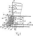
Fig. 1 représente une vue en perspective schématique partiellement arrachée d'un dispositif d'éclairage selon l'invention.Fig. 2 représente une vue en perspective schématique d'une autre forme de réalisation de l'invention d'un dispositif d'éclairage selon l'invention.
Fig. 1 is a schematic perspective view partially broken away of a lighting device according to the invention.Fig. 2 is a schematic perspective view of another embodiment of the invention of a lighting device according to the invention.
Un dispositif d'éclairage pour feux de véhicule selon l'invention, comporte au moins une source de lumière de lumière à diode électroluminescente ou Led associée à un guide de lumière. Selon l'exemple illustré à la
Dans le cas présent, la première source de lumière S1, comprend une série de diodes électroluminescentes ou Led L1 alignées sur un support P1 en étant espacées de façon régulière. Ainsi, deux diodes consécutives L1 de la première source S1 sont séparées d'un pas P qui est, de préférence, supérieur ou égal à 10 mm de manière à éviter une surchauffe du support P1. Le support peut être réalisé de toute manière appropriée, selon l'exemple illustré il comprend un support de circuit imprimé ou PCB sur lequel sont agencées des pistes d'alimentation des diodes L1.In the present case, the first light source S1 comprises a series of light-emitting diodes or LEDs L1 aligned on a support P1, being spaced apart from each other. regular way. Thus, two consecutive diodes L1 of the first source S1 are separated by a pitch P which is preferably greater than or equal to 10 mm so as to avoid overheating of the support P1. The support can be made in any appropriate manner, according to the illustrated example it comprises a printed circuit support or PCB on which are arranged power supply L1 diodes.
Les diodes L1 émettent de la lumière selon une direction principale d'émission Δ sensiblement perpendiculaire au support P1. Chaque diode L1 comprend une optique primaire 01 adaptée pour émettre la lumière selon un cône d'émission qui possède un angle au sommet C. L'ensemble des diodes L1 sont choisies de manière à présenter un même angle au sommet ou angle au sommet moyen C possédant, dans le cas présent, une valeur de 40°.The L1 diodes emit light in a main direction of emission Δ substantially perpendicular to the support P1. Each diode L1 comprises a primary optic 01 adapted to emit light according to a transmission cone which has an angle at the vertex C. The set of diodes L1 are chosen so as to have the same angle at the apex or average apex angle C having, in the present case, a value of 40 °.
Le dispositif d'éclairage selon l'invention comprend, entre la première source de lumière S1 et le premier guide de lumière G1, un manchon diffuseur D1 qui comprend un corps opaque 1 à l'intérieur duquel est aménagé un canal 2 de diffusion rectiligne transparent dont une entrée 3 est située en regard de la première source de lumière L1 et une sortie 4 est située en regard d'une extrémité proximale 5 du premier guide de lumière G1. Le canal de diffusion 2 s'étend selon deux directions à savoir la ligne décrite par l'alignement des diodes L1 et la direction d'émission Δ. Le canal de diffusion possède une largeur ou épaisseur sensiblement égale à l'épaisseur du premier guide de lumière S1 et sa paroi périphérique 6 est sensiblement parallèle à la direction d'émission des diodes L1. La paroi périphérique 6 du canal de diffusion est de couleur blanche de manière que les rayons lumineux issus des diodes se réfléchissent sur ladite paroi périphérique. De manière préférée mais non strictement nécessaire, la paroi périphérique 6 est grainée ou rugueuse de manière à augmenter le caractère diffusant du canal 2 pour qu'en sortie du canal les points chauds formés par les diodes L1 soient peu ou pas perceptibles. Afin d'ajuster, l'effet diffusant il également possible de réalisée la paroi périphérique de manière qu'elle soit brillante ou au contraire mate.The lighting device according to the invention comprises, between the first light source S1 and the first light guide G1, a diffuser sleeve D1 which comprises an
Selon l'exemple illustré, le canal de diffusion 2 est creux en étant ouvert au niveau de son entrée de sorte qu'il est rempli d'air. Toutefois, selon l'invention, le canal de diffusion pourrait être fermé à ces deux extrémités en étant rempli d'un autre gaz que l'air. Le canal de diffusion 2 pourrait également être plein en étant rempli d'un matériau transparent.According to the illustrated example, the
Selon l'exemple de réalisation présenté, le canal de diffusion 2 est dimensionné de manière à optimiser son effet diffusant en optimisant le nombre de réflexion des rayons lumineux émis par les diodes L1 sur la paroi périphérique 6. A cet effet, la hauteur H du canal de diffusion 2, mesurée entre l'entrée et la sortie, vérifie la relation suivante :
- a est un coefficient multiplicateur,
- P est le pas d'espacement des diodes,
- C est l'angle au sommet moyen des cônes d'éclairage en sortie des optiques primaires des diodes électroluminescentes L1,
- et tan la fonction tangente.
- a is a multiplying coefficient,
- P is the spacing pitch of the diodes,
- C is the average apex angle of the illumination cones at the output of the primary optics of the light-emitting diodes L1,
- and tan the tangent function.
De manière préférée, le coefficient a est choisi pour être supérieur ou égal à 1 et de préférence supérieur ou égal à 2. Dans la cas présent le coefficient est choisi pour être compris entre 2 et 2,5 et plus particulièrement avec une valeur égale à 2, valeur que les inventeurs ont identifiée comme offrant le meilleurs compromis entre l'effet diffusant atténuateur des points chaud et encombrement du manchon diffuseur 2.Preferably, the coefficient a is chosen to be greater than or equal to 1 and preferably greater than or equal to 2. In the present case the coefficient is chosen to be between 2 and 2.5 and more particularly with a value equal to 2, a value that the inventors have identified as offering the best compromise between the attenuating diffusing effect of the hot spots and the size of the
Selon l'exemple de réalisation représenté à la
Selon l'exemple illustré, l'élément diffuseur D2 comprend une plaquette transparente qui ferme le canal de diffusion 2 au niveau de sa sortie 4 et qui est grainée sur ces faces avant et arrière.According to the illustrated example, the diffuser element D2 comprises a transparent plate which closes the
Le premier guide de lumière G1 associé à la première source de lumière S1 est réalisé de manière à former une sorte de rideau de lumière homogène lorsque la source de lumière est allumée. Ainsi le premier guide de lumière G1 se présente sous la forme d'une plaque ou d'une coque qui s'étend, d'une part, selon ou parallèlement à la direction d'émission de la lumière Δ et, d'autre part, au droit de la source de lumière S1 en suivant la ligne formée par cette dernière. Le guide de lumière comprend une extrémité proximale 5 d'entrée de la lumière et l'opposée de celle-ci une extrémité distale 10. Le premier guide de lumière G1 comprend, entre ses extrémités proximale 5 et distale 10, une face latérale ou avant 11 d'émission de la lumière et à l'opposée de la face avant 11 une face latérale arrière 12 comprenant des moyens 13 de réflexion ou de renvoi de la lumière vers la face avant 11.The first light guide G1 associated with the first light source S1 is made to form a kind of homogeneous light curtain when the light source is turned on. Thus the first light guide G1 is in the form of a plate or shell which extends, on the one hand, along or parallel to the light emission direction Δ and on the other hand , at the right of the light source S1 along the line formed by the latter. The light guide includes a
Selon, l'exemple illustré les moyens de réflexion comprennent des facettes associées à une diminution en escalier de l'épaisseur du premier guide G1 en direction de son extrémité distale, l'épaisseur du guide G1 étant mesurée entre ses faces avant 11 et arrière 12.According to the illustrated example, the reflection means comprise facets associated with a stepwise decrease in the thickness of the first guide G1 towards its distal end, the thickness of the guide G1 being measured between its front faces 11 and rear 12 .
Par ailleurs, selon l'exemple illustré, le dispositif d'éclairage comprend un masque M1 s'étendant au moins entre la première source de lumière S1 et l'extrémité proximale 5du premier guide de lumière G1 du côté de la face d'émission 11. Le masque M1 permet d'occulter toute lumière parasite qui pourrait être perçue par un observateur extérieur lors de l'allumage de la première source de lumière S1.Furthermore, according to the illustrated example, the lighting device comprises a mask M1 extending at least between the first light source S1 and the
L'ensemble formé par la première source de lumière S1, le manchon diffuseur D1 et le premier guide de lumière permet d'obtenir lors de l'allumage de la première source S1 une illumination homogène de la face avant 11 du premier guide 1 sans point chaud ce qui est particulièrement adapté à la réalisation d'une lanterne ou d'un feu arrière.The assembly formed by the first light source S1, the diffuser sleeve D1 and the first light guide makes it possible to obtain, during the ignition of the first source S1, a homogeneous illumination of the
Selon l'exemple illustré, le dispositif d'éclairage comprend un deuxième ensemble d'éclairage comprenant une deuxième source de lumière à Led S2 et un deuxième guide de lumière G2. Ce deuxième ensemble d'éclairage est destiné à former un feu stop ou un indicateur de changement de direction.According to the illustrated example, the lighting device comprises a second lighting assembly comprising a second Led light source S2 and a second light guide G2. This second lighting assembly is intended to form a stop light or a change of direction indicator.
La deuxième source de lumière S2 s'étend selon une ligne et émet de la lumière selon une deuxième direction d'émission Δ' qui dans le cas présent est sensiblement parallèle à la direction d'émission Δ de la première source S1.The second light source S2 extends along a line and emits light along a second direction of emission Δ 'which in this case is substantially parallel to the emission direction Δ of the first source S1.
Le deuxième guide de lumière G2 présente ici une structure sensiblement analogue à celle du premier guide de lumière G1. Ainsi le deuxième guide de lumière G2 se présente sous la forme d'une plaque ou d'une coque qui s'étend, d'une part, selon la deuxième direction principale d'émission Δ' et, d'autre part, au droit de la deuxième source de lumière en suivant la ligne formée par cette dernière. Le deuxième guide de lumière G1 comprend alors une extrémité proximale 20 de réception de la lumière orientée vers la deuxième source de lumière S2 et à l'opposé de l'extrémité proximale une extrémité distale 21. Le deuxième guide de lumière G2 comprend entre les extrémités proximale 20 et distale 21 une face latérale ou avant 22 d'émission de la lumière et, à l'opposé de la face latérale d'émission 22, une face latérale arrière 23 comprenant des moyens 24 de réflexion de la lumière vers la face latérale d'émission 23.The second light guide G2 here has a structure substantially similar to that of the first light guide G1. Thus the second light guide G2 is in the form of a plate or a shell which extends, on the one hand, according to the second main direction of emission Δ 'and, on the other hand, to the right the second light source along the line formed by the latter. The second light guide G1 then comprises a
Le deuxième ensemble d'éclairage comprend en outre un élément collimateur 35 interposé entre l'extrémité proximale 20 du deuxième guide de lumière G2 et la deuxième source de lumière S2 de manière à assurer une transmission au deuxième guide de lumière G2 de la majeur partie, voire de l'intégralité, de la lumière émise par la deuxième source de lumière S2.The second lighting assembly further comprises a collimator element 35 interposed between the
Selon l'exemple illustré, les faces avant 11 et 20 des guides de lumière sont planes toutefois elles pourraient être incurvées en étant concave ou convexe.According to the illustrated example, the front faces 11 and 20 of the light guides are flat however they could be curved by being concave or convex.
De plus, les sources de lumière sont ici formées par des alignements de diodes sur des supports ou PCB. Toutefois, une source de lumière d'un dispositif selon l'invention n'est pas nécessairement réalisée de cette manière.In addition, the light sources are here formed by alignments of diodes on supports or PCBs. However, a light source of a device according to the invention is not necessarily realized in this way.
Ainsi la
Selon l'exemple de réalisation illustré
Selon cet exemple, le manchon diffuseur D1 ne comprend pas d'élément diffuseur et présente une hauteur H qui vérifie la relation suivante :
- a' est un coefficient multiplicateur,
- E est l'épaisseur du guide primaire mesurée parallèlement à la direction d'émission Δ,
- a 'is a multiplying coefficient,
- E is the thickness of the primary guide measured parallel to the direction of emission Δ,
De manière préférée, le coefficient a' est choisi pour être supérieur ou égal à 2 et de préférence supérieur ou égal à 3. Dans la cas présent le coefficient est choisi pour être compris entre 3 et 4 et plus particulièrement avec une valeur égale à 3, valeur que les inventeurs ont identifiée comme offrant le meilleurs compromis entre l'effet diffusant atténuateur des points chaud et encombrement du manchon diffuseur 2 utilisé en association avec une source de lumière à guide de lumière primaire tel que décrit en relation avec la
Il doit être noté que selon la variante de réalisation décrite en relation avec la
Bien entendu, diverses autres variantes de réalisation d'un dispositif d'éclairage selon l'invention pourraient être envisagées dans le cadre des revendications annexées.Of course, various other embodiments of a lighting device according to the invention could be envisaged within the scope of the appended claims.
Claims (15)
- A lighting device for vehicle lights, comprising at least:- a first LED light source (S1) extending along a line and emitting light in a first main direction of emission (Δ),- a first light guide (G1) associated with the first light source (S1) formed by a shell extending, on the one hand, in the main direction of emission and, on the other hand, perpendicular to the light source (S1) following the line formed by the latter and comprising a proximal end (5) for light reception, directed towards the light source and, opposite the proximal end (5), a distal end (10) and, between the proximal and distal ends, a lateral face (11) of light emission and, opposite the lateral face of emission, a rear lateral face (12) comprising means (13) for reflecting the light towards the lateral face of emission (11),characterized in that it comprises, between the proximal end of the first light guide and the first light source, a scattering sleeve (D1) comprising an opaque body (1) delimiting a transparent rectilinear scattering channel (2) whose peripheral wall (6) is white and that comprises an inlet (3) opposite the light source and an outlet (4) opposite the proximal end (5) of the light guide.
- The lighting device according to the preceding claim,characterized in that the peripheral wall (6) of the scattering channel (2) is rough or grainy.
- The lighting device according to one of the preceding claims,characterized in that the peripheral wall (6) of the scattering channel (2) is bright.
- The lighting device according to claim 1 or 2,characterized in that the peripheral wall (6) of the scattering channel (2) is matt.
- The lighting device according to one of the preceding claims,characterized in that the scattering channel (2) is filled with gas.
- The lighting device according to the preceding claims,characterized in that the scattering channel (2) is open at the inlet (3).
- The lighting device according to one of the preceding claims,characterized in that the first light source (S1) comprises at least a series of electroluminescent diodes (L1) aligned with each other, two consecutive diodes of the series being spaced by a same spacing pitch (P).
- The lighting device according to the preceding claim,characterized in that the spacing pitch (P) is higher than or equal to 10 mm.
- The lighting device according to claim 8 or 9,characterized in that the scattering channel (2) has a height H, measured between the inlet and the outlet, that satisfies the following relation:
 - a is a coefficient higher than or equal to 1, preferably higher than or equal to 2, and more particularly preferably comprised between 2 and 2.5,- P is the diode spacing pitch,- C is the average apex angle of the lighting cones at the exit of the primary optics of the electroluminescent diodes,- and tan is the tangent function.
 - The lighting device according to one of claims 1 to 6,characterized in that:- the first light source comprises, on the one hand, a primary light guide (30) of elongated shape and comprising the lateral light scattering means (31) and, on the other hand, at least one electroluminescent diode arranged at least one end of the primary light guide to emit the light into the primary light guide,- and the scattering channel (2) of the scattering sleeve (D1) has a height H, measured between the inlet and the outlet, that satisfies the following relation:
 - a' is a multiplication coefficient, higher than or equal to 2, preferably, higher than or equal to 3, and more particularly preferably, comprised between 3 and 4,- E is the thickness of the primary guide measured parallel to the direction of emission Δ.
 - The lighting device according to one of the preceding claims,characterized in that the scattering sleeve (D1) comprises, at the outlet of the scattering channel (2), a scattering element (D2) working in transmission.
- The lighting device according to one of the preceding claims,characterized in that it comprises:- at least one second LED light source (S2) extending along a line and emitting light in a second main direction of emission (Δ'),- a second light guide (G2) associated with the second light source (S2) formed by a shell extending, on the one hand, in the second main direction of emission and, on the other hand, perpendicular to the second light source (S2) following the line formed by the latter and comprising a proximal end for light reception, directed towards the second light source and, opposite the proximal end, a distal end and, between the proximal and distal ends, a lateral face of light emission and, opposite the lateral face of emission, a rear lateral face comprising means for reflecting the light towards the lateral face of emission,- between the proximal end of the second light guide and the second light source, a collimator element (25).
- The lighting device according to the preceding claim,characterized in that:- the unit formed by the first light source (S1) and the first light guide (G1) constitutes a lantern or a rear light,- and the unit formed by the second light source (S2) and the second light guide (G2) constitutes a stop light or a direction indicator light.
- The lighting device according to one of the preceding claims,characterized in that the thickness of each light guide reduces towards its distal end.
- The lighting device according to one of the preceding claims,characterized in that the light reflecting means (13, 24) of each light guide comprise facets and/or micro-lines formed in the rear face of each light guide.


Applications Claiming Priority (2)
| Application Number | Priority Date | Filing Date | Title |
|---|---|---|---|
| FR1361321AFR3013420B1 (en) | 2013-11-18 | 2013-11-18 | LIGHTING AND / OR SIGNALING SYSTEM WITH GUIDES FOR MOTOR VEHICLE |
| PCT/FR2014/052956WO2015071620A1 (en) | 2013-11-18 | 2014-11-18 | Lighting and/or signalling system with light guides for a vehicle |
Publications (2)
| Publication Number | Publication Date |
|---|---|
| EP3071449A1 EP3071449A1 (en) | 2016-09-28 |
| EP3071449B1true EP3071449B1 (en) | 2017-08-02 |
Family
ID=50624655
Family Applications (1)
| Application Number | Title | Priority Date | Filing Date |
|---|---|---|---|
| EP14809943.5AActiveEP3071449B1 (en) | 2013-11-18 | 2014-11-18 | Lighting and/or signalling system with light guides for a vehicle |
Country Status (4)
| Country | Link |
|---|---|
| EP (1) | EP3071449B1 (en) |
| KR (1) | KR102266373B1 (en) |
| FR (1) | FR3013420B1 (en) |
| WO (1) | WO2015071620A1 (en) |
Families Citing this family (10)
| Publication number | Priority date | Publication date | Assignee | Title |
|---|---|---|---|---|
| FR3042751B1 (en)* | 2015-10-23 | 2018-09-07 | Automotive Lighting Rear Lamps France | COMPACT LIGHTING AND / OR SIGNALING DEVICE FOR VEHICLE |
| DE102016206811A1 (en)* | 2016-04-21 | 2017-11-09 | Audi Ag | Illuminating device with a milky, dull illuminated surface |
| US10663138B2 (en) | 2017-07-20 | 2020-05-26 | Valeo North America, Inc. | Light reflector systems and methods |
| KR102116400B1 (en) | 2018-08-01 | 2020-05-28 | 이경현 | Survival Apparatus for Distress Rescue Ship |
| KR102116397B1 (en) | 2018-12-17 | 2020-06-05 | 이경현 | Survival Apparatus for Distress Rescue Ship |
| IT201900024919A1 (en)* | 2019-12-20 | 2021-06-20 | Olsa Spa | LIGHT GUIDE FOR HEADLIGHTS AND RELATIVE HEADLIGHT FOR CARS. |
| DE102020132976A1 (en) | 2019-12-20 | 2021-06-24 | Olsa S.P.A. | LIGHT GUIDES FOR LUMINAIRES AND ASSOCIATED LUMINAIRES FOR VEHICLES |
| DE102022117892A1 (en) | 2022-07-18 | 2024-01-18 | Marelli Automotive Lighting Reutlingen (Germany) GmbH | Light guide with light coupling |
| US12276394B2 (en) | 2022-11-14 | 2025-04-15 | Atieva, Inc. | Homogeneous rear combination lamp without outer lens |
| EP4435318A1 (en)* | 2023-03-24 | 2024-09-25 | ZKW Group GmbH | Illumination device for a vehicle |
Family Cites Families (20)
| Publication number | Priority date | Publication date | Assignee | Title |
|---|---|---|---|---|
| FR1200281A (en) | 1959-08-13 | 1959-12-21 | Ballpoint pen with bent tube, single ball or several balls of different colors on the same plane | |
| US5772304A (en)* | 1996-10-02 | 1998-06-30 | Raytheon Company | Optical fiber-to-planar lightpipe grooved optical coupler |
| DE19806526A1 (en) | 1998-02-17 | 1999-08-19 | Hella Kg Hueck & Co | Lighting device for motor vehicles |
| FR2819040B1 (en) | 2001-01-02 | 2003-09-12 | Valeo Vision | OPTICAL OR STYLE COMPONENT FOR A LIGHTING OR SIGNALING DEVICE FOR A MOTOR VEHICLE |
| DE10101795A1 (en) | 2001-01-17 | 2002-07-18 | Bosch Gmbh Robert | Flashing light, especially front flashing light, for motor vehicles has boundary light source in part of light conducting element in part of path of light from flashing light source |
| DE10311317A1 (en) | 2003-03-14 | 2004-09-23 | Volkswagen Ag | Lighting device for vehicle, e.g. flashing light in external mirror, has several output coupling structures arranged on surface of light conductor to lie essentially at reflector surfaces focal point |
| FR2868506B1 (en) | 2004-03-30 | 2006-05-19 | Axo Scintex Cie Equip Automobi | SIGNALING LIGHT OF MOTOR VEHICLE |
| DE102004054732B4 (en)* | 2004-11-14 | 2006-11-23 | Fer Fahrzeugelektrik Gmbh | Lichtleiteranordung |
| DE102005021079B4 (en)* | 2005-05-06 | 2010-07-01 | Automotive Lighting Reutlingen Gmbh | Light guide with motor vehicle light |
| US7229196B2 (en)* | 2005-06-10 | 2007-06-12 | Ilight Technologies, Inc. | Illumination device for simulating neon or similar lighting in the shape of a toroid |
| JP4780788B2 (en)* | 2007-01-31 | 2011-09-28 | スタンレー電気株式会社 | LED lamp unit |
| JP4978560B2 (en)* | 2008-05-21 | 2012-07-18 | トヨタ紡織株式会社 | Assist grip lighting device for vehicle |
| US7905639B2 (en)* | 2008-05-28 | 2011-03-15 | Osram Sylvania Inc. | Side-loaded light emitting diode module for automotive rear combination lamps |
| EP2159477B1 (en)* | 2008-08-25 | 2015-01-14 | Koito Manufacturing Co., Ltd | Vehicle lamp using a light guide |
| US8485704B2 (en)* | 2009-10-14 | 2013-07-16 | Koito Manufacturing Co., Ltd. | Lamp unit and vehicle lamp |
| DE102010006348A1 (en)* | 2010-01-30 | 2011-08-04 | Hella KGaA Hueck & Co., 59557 | Illumination device for car, has two light units comprising two planar light guide elements, respectively, where back sides and/or front sides of guide elements are provided with same uncoupling element |
| DE102010046342B4 (en)* | 2010-09-23 | 2012-11-08 | Audi Ag | Lighting device and vehicle with a lighting device |
| DE102011050422A1 (en)* | 2011-05-17 | 2012-11-22 | Dr. Ing. H.C. F. Porsche Aktiengesellschaft | Light i.e. rear light, for motor car, has light guiding element whose upper and lower light exit surfaces are upwardly displaced against middle light exit surface that is positioned between upper and lower light exit surfaces |
| DE102011118219A1 (en)* | 2011-11-11 | 2013-05-16 | Volkswagen Aktiengesellschaft | Shining device for headlight in front region of motor car, has light conductor anti-swiveling arranged in holding element, where holding element is associated with tinted windshield that faces light exit surface of light conductor |
| FR2986306B1 (en)* | 2012-01-31 | 2018-02-09 | Automotive Lighting Rear Lamps France | LED LIGHTING DEVICE WITH DIFFUSER SYSTEM |
- 2013
- 2013-11-18FRFR1361321Apatent/FR3013420B1/enactiveActive
- 2014
- 2014-11-18EPEP14809943.5Apatent/EP3071449B1/enactiveActive
- 2014-11-18WOPCT/FR2014/052956patent/WO2015071620A1/enactiveApplication Filing
- 2014-11-18KRKR1020167015639Apatent/KR102266373B1/enactiveActive
Non-Patent Citations (1)
| Title |
|---|
| None* |
Also Published As
| Publication number | Publication date |
|---|---|
| WO2015071620A1 (en) | 2015-05-21 |
| FR3013420B1 (en) | 2018-10-26 |
| EP3071449A1 (en) | 2016-09-28 |
| KR20160123286A (en) | 2016-10-25 |
| KR102266373B1 (en) | 2021-06-17 |
| FR3013420A1 (en) | 2015-05-22 |
Similar Documents
| Publication | Publication Date | Title |
|---|---|---|
| EP3071449B1 (en) | Lighting and/or signalling system with light guides for a vehicle | |
| EP3008378B1 (en) | Lighting module for motor vehicles having continuously evolving light homogeneity | |
| EP1775511B1 (en) | Vehicle lighting or signalling device with a light guide | |
| EP2476947B1 (en) | Lighting or signalling device with an optical guide for an automobile vehicle | |
| EP1895228B1 (en) | Lighting or signalling device with the appearance of a high-performance light guide for an automobile vehicle | |
| EP2510277B1 (en) | Lantern or position light for motor vehicle light | |
| EP3014172B1 (en) | Indirect lighting device for a motor vehicle tail light | |
| FR2828727A1 (en) | VEHICLE LAMP HAVING PHOTOEMISSIVE DIODES | |
| FR2934353A1 (en) | Optical system for producing light beams in e.g. signaling or lighting device of motor vehicle, has reflector elements arranged at central zone's portion of diffusion module, and deviating light rays towards front of system | |
| EP2317214A1 (en) | Lighting or signalling device for an automobile comprising a light guide | |
| FR2829224A1 (en) | VEHICLE LAMP AND METHOD OF OPERATING SAME | |
| EP2809985B1 (en) | Device for making the appearance of a motor vehicle signal light uniform | |
| EP1978295B1 (en) | Luminous signalling device capable of independently emitting two signalling beams with the same intensity and different luminances | |
| EP2703220B1 (en) | Lighting and/or signalling device for an automobile | |
| EP2991858B1 (en) | 3d-effect led illuminating device with scattering system | |
| FR3056691B1 (en) | OPTICAL MODULE FOR A MOTOR VEHICLE PROJECTOR WITH ADAPTIVE LIGHTING FUNCTION, COMPRISING AN OPTICAL LIGHT BEAM REFLECTING SYSTEM | |
| FR3117959A1 (en) | VEHICLE HEADLIGHT WITH A LIGHTING FUNCTION LOCATED BEHIND A SIGNALING FUNCTION | |
| EP2809546B1 (en) | Led lighting device including a diffuser system | |
| FR3075312A1 (en) | LUMINOUS SIGNALING DEVICE FOR MOTOR VEHICLE PROVIDING IMPROVED VISUAL COMFORT FOR ROAD USERS | |
| FR3133071A1 (en) | Optical part with several serial output zones | |
| WO2025093477A1 (en) | Motor vehicle lighting system | |
| FR3087520A1 (en) | LIGHT MODULE PROVIDING TWO PHOTOMETRIC FUNCTIONS WITH DISTINCT LIGHT SIGNATURES |
Legal Events
| Date | Code | Title | Description |
|---|---|---|---|
| PUAI | Public reference made under article 153(3) epc to a published international application that has entered the european phase | Free format text:ORIGINAL CODE: 0009012 | |
| 17P | Request for examination filed | Effective date:20160618 | |
| AK | Designated contracting states | Kind code of ref document:A1 Designated state(s):AL AT BE BG CH CY CZ DE DK EE ES FI FR GB GR HR HU IE IS IT LI LT LU LV MC MK MT NL NO PL PT RO RS SE SI SK SM TR | |
| AX | Request for extension of the european patent | Extension state:BA ME | |
| DAX | Request for extension of the european patent (deleted) | ||
| GRAP | Despatch of communication of intention to grant a patent | Free format text:ORIGINAL CODE: EPIDOSNIGR1 | |
| INTG | Intention to grant announced | Effective date:20170411 | |
| GRAS | Grant fee paid | Free format text:ORIGINAL CODE: EPIDOSNIGR3 | |
| GRAA | (expected) grant | Free format text:ORIGINAL CODE: 0009210 | |
| AK | Designated contracting states | Kind code of ref document:B1 Designated state(s):AL AT BE BG CH CY CZ DE DK EE ES FI FR GB GR HR HU IE IS IT LI LT LU LV MC MK MT NL NO PL PT RO RS SE SI SK SM TR | |
| REG | Reference to a national code | Ref country code:CH Ref legal event code:EP Ref country code:AT Ref legal event code:REF Ref document number:914062 Country of ref document:AT Kind code of ref document:T Effective date:20170815 | |
| REG | Reference to a national code | Ref country code:IE Ref legal event code:FG4D Free format text:LANGUAGE OF EP DOCUMENT: FRENCH | |
| REG | Reference to a national code | Ref country code:DE Ref legal event code:R096 Ref document number:602014012699 Country of ref document:DE | |
| REG | Reference to a national code | Ref country code:FR Ref legal event code:PLFP Year of fee payment:4 | |
| REG | Reference to a national code | Ref country code:NL Ref legal event code:MP Effective date:20170802 | |
| REG | Reference to a national code | Ref country code:AT Ref legal event code:MK05 Ref document number:914062 Country of ref document:AT Kind code of ref document:T Effective date:20170802 | |
| REG | Reference to a national code | Ref country code:LT Ref legal event code:MG4D | |
| PG25 | Lapsed in a contracting state [announced via postgrant information from national office to epo] | Ref country code:NO Free format text:LAPSE BECAUSE OF FAILURE TO SUBMIT A TRANSLATION OF THE DESCRIPTION OR TO PAY THE FEE WITHIN THE PRESCRIBED TIME-LIMIT Effective date:20171102 Ref country code:SE Free format text:LAPSE BECAUSE OF FAILURE TO SUBMIT A TRANSLATION OF THE DESCRIPTION OR TO PAY THE FEE WITHIN THE PRESCRIBED TIME-LIMIT Effective date:20170802 Ref country code:FI Free format text:LAPSE BECAUSE OF FAILURE TO SUBMIT A TRANSLATION OF THE DESCRIPTION OR TO PAY THE FEE WITHIN THE PRESCRIBED TIME-LIMIT Effective date:20170802 Ref country code:LT Free format text:LAPSE BECAUSE OF FAILURE TO SUBMIT A TRANSLATION OF THE DESCRIPTION OR TO PAY THE FEE WITHIN THE PRESCRIBED TIME-LIMIT Effective date:20170802 Ref country code:NL Free format text:LAPSE BECAUSE OF FAILURE TO SUBMIT A TRANSLATION OF THE DESCRIPTION OR TO PAY THE FEE WITHIN THE PRESCRIBED TIME-LIMIT Effective date:20170802 Ref country code:AT Free format text:LAPSE BECAUSE OF FAILURE TO SUBMIT A TRANSLATION OF THE DESCRIPTION OR TO PAY THE FEE WITHIN THE PRESCRIBED TIME-LIMIT Effective date:20170802 Ref country code:HR Free format text:LAPSE BECAUSE OF FAILURE TO SUBMIT A TRANSLATION OF THE DESCRIPTION OR TO PAY THE FEE WITHIN THE PRESCRIBED TIME-LIMIT Effective date:20170802 | |
| PG25 | Lapsed in a contracting state [announced via postgrant information from national office to epo] | Ref country code:BG Free format text:LAPSE BECAUSE OF FAILURE TO SUBMIT A TRANSLATION OF THE DESCRIPTION OR TO PAY THE FEE WITHIN THE PRESCRIBED TIME-LIMIT Effective date:20171102 Ref country code:ES Free format text:LAPSE BECAUSE OF FAILURE TO SUBMIT A TRANSLATION OF THE DESCRIPTION OR TO PAY THE FEE WITHIN THE PRESCRIBED TIME-LIMIT Effective date:20170802 Ref country code:RS Free format text:LAPSE BECAUSE OF FAILURE TO SUBMIT A TRANSLATION OF THE DESCRIPTION OR TO PAY THE FEE WITHIN THE PRESCRIBED TIME-LIMIT Effective date:20170802 Ref country code:LV Free format text:LAPSE BECAUSE OF FAILURE TO SUBMIT A TRANSLATION OF THE DESCRIPTION OR TO PAY THE FEE WITHIN THE PRESCRIBED TIME-LIMIT Effective date:20170802 Ref country code:IS Free format text:LAPSE BECAUSE OF FAILURE TO SUBMIT A TRANSLATION OF THE DESCRIPTION OR TO PAY THE FEE WITHIN THE PRESCRIBED TIME-LIMIT Effective date:20171202 Ref country code:PL Free format text:LAPSE BECAUSE OF FAILURE TO SUBMIT A TRANSLATION OF THE DESCRIPTION OR TO PAY THE FEE WITHIN THE PRESCRIBED TIME-LIMIT Effective date:20170802 Ref country code:GR Free format text:LAPSE BECAUSE OF FAILURE TO SUBMIT A TRANSLATION OF THE DESCRIPTION OR TO PAY THE FEE WITHIN THE PRESCRIBED TIME-LIMIT Effective date:20171103 | |
| PG25 | Lapsed in a contracting state [announced via postgrant information from national office to epo] | Ref country code:CZ Free format text:LAPSE BECAUSE OF FAILURE TO SUBMIT A TRANSLATION OF THE DESCRIPTION OR TO PAY THE FEE WITHIN THE PRESCRIBED TIME-LIMIT Effective date:20170802 Ref country code:RO Free format text:LAPSE BECAUSE OF FAILURE TO SUBMIT A TRANSLATION OF THE DESCRIPTION OR TO PAY THE FEE WITHIN THE PRESCRIBED TIME-LIMIT Effective date:20170802 Ref country code:DK Free format text:LAPSE BECAUSE OF FAILURE TO SUBMIT A TRANSLATION OF THE DESCRIPTION OR TO PAY THE FEE WITHIN THE PRESCRIBED TIME-LIMIT Effective date:20170802 | |
| REG | Reference to a national code | Ref country code:DE Ref legal event code:R097 Ref document number:602014012699 Country of ref document:DE | |
| PG25 | Lapsed in a contracting state [announced via postgrant information from national office to epo] | Ref country code:SM Free format text:LAPSE BECAUSE OF FAILURE TO SUBMIT A TRANSLATION OF THE DESCRIPTION OR TO PAY THE FEE WITHIN THE PRESCRIBED TIME-LIMIT Effective date:20170802 Ref country code:EE Free format text:LAPSE BECAUSE OF FAILURE TO SUBMIT A TRANSLATION OF THE DESCRIPTION OR TO PAY THE FEE WITHIN THE PRESCRIBED TIME-LIMIT Effective date:20170802 Ref country code:IT Free format text:LAPSE BECAUSE OF FAILURE TO SUBMIT A TRANSLATION OF THE DESCRIPTION OR TO PAY THE FEE WITHIN THE PRESCRIBED TIME-LIMIT Effective date:20170802 Ref country code:SK Free format text:LAPSE BECAUSE OF FAILURE TO SUBMIT A TRANSLATION OF THE DESCRIPTION OR TO PAY THE FEE WITHIN THE PRESCRIBED TIME-LIMIT Effective date:20170802 | |
| PLBE | No opposition filed within time limit | Free format text:ORIGINAL CODE: 0009261 | |
| STAA | Information on the status of an ep patent application or granted ep patent | Free format text:STATUS: NO OPPOSITION FILED WITHIN TIME LIMIT | |
| PG25 | Lapsed in a contracting state [announced via postgrant information from national office to epo] | Ref country code:MC Free format text:LAPSE BECAUSE OF FAILURE TO SUBMIT A TRANSLATION OF THE DESCRIPTION OR TO PAY THE FEE WITHIN THE PRESCRIBED TIME-LIMIT Effective date:20170802 | |
| 26N | No opposition filed | Effective date:20180503 | |
| PG25 | Lapsed in a contracting state [announced via postgrant information from national office to epo] | Ref country code:CH Free format text:LAPSE BECAUSE OF NON-PAYMENT OF DUE FEES Effective date:20171130 Ref country code:LI Free format text:LAPSE BECAUSE OF NON-PAYMENT OF DUE FEES Effective date:20171130 | |
| PG25 | Lapsed in a contracting state [announced via postgrant information from national office to epo] | Ref country code:LU Free format text:LAPSE BECAUSE OF NON-PAYMENT OF DUE FEES Effective date:20171118 Ref country code:SI Free format text:LAPSE BECAUSE OF FAILURE TO SUBMIT A TRANSLATION OF THE DESCRIPTION OR TO PAY THE FEE WITHIN THE PRESCRIBED TIME-LIMIT Effective date:20170802 | |
| REG | Reference to a national code | Ref country code:BE Ref legal event code:MM Effective date:20171130 | |
| REG | Reference to a national code | Ref country code:IE Ref legal event code:MM4A | |
| PG25 | Lapsed in a contracting state [announced via postgrant information from national office to epo] | Ref country code:MT Free format text:LAPSE BECAUSE OF FAILURE TO SUBMIT A TRANSLATION OF THE DESCRIPTION OR TO PAY THE FEE WITHIN THE PRESCRIBED TIME-LIMIT Effective date:20170802 | |
| PG25 | Lapsed in a contracting state [announced via postgrant information from national office to epo] | Ref country code:IE Free format text:LAPSE BECAUSE OF NON-PAYMENT OF DUE FEES Effective date:20171118 | |
| PG25 | Lapsed in a contracting state [announced via postgrant information from national office to epo] | Ref country code:BE Free format text:LAPSE BECAUSE OF NON-PAYMENT OF DUE FEES Effective date:20171130 | |
| PG25 | Lapsed in a contracting state [announced via postgrant information from national office to epo] | Ref country code:HU Free format text:LAPSE BECAUSE OF FAILURE TO SUBMIT A TRANSLATION OF THE DESCRIPTION OR TO PAY THE FEE WITHIN THE PRESCRIBED TIME-LIMIT; INVALID AB INITIO Effective date:20141118 | |
| PG25 | Lapsed in a contracting state [announced via postgrant information from national office to epo] | Ref country code:CY Free format text:LAPSE BECAUSE OF FAILURE TO SUBMIT A TRANSLATION OF THE DESCRIPTION OR TO PAY THE FEE WITHIN THE PRESCRIBED TIME-LIMIT Effective date:20170802 | |
| PG25 | Lapsed in a contracting state [announced via postgrant information from national office to epo] | Ref country code:MK Free format text:LAPSE BECAUSE OF FAILURE TO SUBMIT A TRANSLATION OF THE DESCRIPTION OR TO PAY THE FEE WITHIN THE PRESCRIBED TIME-LIMIT Effective date:20170802 | |
| PG25 | Lapsed in a contracting state [announced via postgrant information from national office to epo] | Ref country code:TR Free format text:LAPSE BECAUSE OF FAILURE TO SUBMIT A TRANSLATION OF THE DESCRIPTION OR TO PAY THE FEE WITHIN THE PRESCRIBED TIME-LIMIT Effective date:20170802 | |
| PG25 | Lapsed in a contracting state [announced via postgrant information from national office to epo] | Ref country code:PT Free format text:LAPSE BECAUSE OF FAILURE TO SUBMIT A TRANSLATION OF THE DESCRIPTION OR TO PAY THE FEE WITHIN THE PRESCRIBED TIME-LIMIT Effective date:20170802 | |
| PG25 | Lapsed in a contracting state [announced via postgrant information from national office to epo] | Ref country code:AL Free format text:LAPSE BECAUSE OF FAILURE TO SUBMIT A TRANSLATION OF THE DESCRIPTION OR TO PAY THE FEE WITHIN THE PRESCRIBED TIME-LIMIT Effective date:20170802 | |
| P01 | Opt-out of the competence of the unified patent court (upc) registered | Effective date:20240207 | |
| PGFP | Annual fee paid to national office [announced via postgrant information from national office to epo] | Ref country code:DE Payment date:20241108 Year of fee payment:11 | |
| PGFP | Annual fee paid to national office [announced via postgrant information from national office to epo] | Ref country code:GB Payment date:20241122 Year of fee payment:11 | |
| PGFP | Annual fee paid to national office [announced via postgrant information from national office to epo] | Ref country code:FR Payment date:20241120 Year of fee payment:11 |