EP3071131B1 - Exchanger surgical access port assembly - Google Patents
Exchanger surgical access port assemblyDownload PDFInfo
- Publication number
- EP3071131B1 EP3071131B1EP14849207.7AEP14849207AEP3071131B1EP 3071131 B1EP3071131 B1EP 3071131B1EP 14849207 AEP14849207 AEP 14849207AEP 3071131 B1EP3071131 B1EP 3071131B1
- Authority
- EP
- European Patent Office
- Prior art keywords
- access port
- surgical
- surgical access
- instrument
- port assembly
- Prior art date
- Legal status (The legal status is an assumption and is not a legal conclusion. Google has not performed a legal analysis and makes no representation as to the accuracy of the status listed.)
- Active
Links
- 229920001971elastomerPolymers0.000claimsdescription5
- 239000004033plasticSubstances0.000claimsdescription5
- 229920003023plasticPolymers0.000claimsdescription5
- 239000000806elastomerSubstances0.000claimsdescription3
- 229920000642polymerPolymers0.000claimsdescription3
- 230000006835compressionEffects0.000claimsdescription2
- 238000007906compressionMethods0.000claimsdescription2
- -1fluorocarbonsPolymers0.000claimsdescription2
- 239000006260foamSubstances0.000claimsdescription2
- 150000002825nitrilesChemical class0.000claimsdescription2
- 229920001296polysiloxanePolymers0.000claimsdescription2
- 239000005060rubberSubstances0.000claimsdescription2
- 238000001356surgical procedureMethods0.000description26
- 238000007789sealingMethods0.000description16
- 238000000034methodMethods0.000description13
- 210000003195fasciaAnatomy0.000description12
- 208000014674injuryDiseases0.000description11
- 230000008733traumaEffects0.000description10
- 238000002357laparoscopic surgeryMethods0.000description9
- 230000000712assemblyEffects0.000description6
- 238000000429assemblyMethods0.000description6
- 239000012636effectorSubstances0.000description6
- 238000003780insertionMethods0.000description6
- 230000037431insertionEffects0.000description6
- 231100000241scarToxicity0.000description6
- 230000037390scarringEffects0.000description6
- 210000001519tissueAnatomy0.000description6
- 230000008901benefitEffects0.000description5
- 239000000463materialSubstances0.000description4
- 230000007246mechanismEffects0.000description4
- 239000000523sampleSubstances0.000description4
- 230000003187abdominal effectEffects0.000description3
- 239000011810insulating materialSubstances0.000description3
- 230000003287optical effectEffects0.000description3
- 210000000056organAnatomy0.000description3
- 238000011084recoveryMethods0.000description3
- 208000032544CicatrixDiseases0.000description2
- 208000005646PneumoperitoneumDiseases0.000description2
- 210000001015abdomenAnatomy0.000description2
- 238000002324minimally invasive surgeryMethods0.000description2
- 230000035515penetrationEffects0.000description2
- 239000004417polycarbonateSubstances0.000description2
- 229920000515polycarbonatePolymers0.000description2
- 230000008569processEffects0.000description2
- 230000037387scarsEffects0.000description2
- 206010019909HerniaDiseases0.000description1
- 206010020751HypersensitivityDiseases0.000description1
- 229920000106Liquid crystal polymerPolymers0.000description1
- 239000004977Liquid-crystal polymers (LCPs)Substances0.000description1
- 208000002847Surgical WoundDiseases0.000description1
- 208000027418Wounds and injuryDiseases0.000description1
- 238000012084abdominal surgeryMethods0.000description1
- 210000003815abdominal wallAnatomy0.000description1
- 230000009471actionEffects0.000description1
- 208000030961allergic reactionDiseases0.000description1
- 238000001574biopsyMethods0.000description1
- 210000000746body regionAnatomy0.000description1
- 238000011109contaminationMethods0.000description1
- 239000002537cosmeticSubstances0.000description1
- 230000006378damageEffects0.000description1
- 238000013461designMethods0.000description1
- 230000001627detrimental effectEffects0.000description1
- 201000004356excessive tearingDiseases0.000description1
- 230000006870functionEffects0.000description1
- 239000011521glassSubstances0.000description1
- 230000036541healthEffects0.000description1
- 210000000936intestineAnatomy0.000description1
- 238000003973irrigationMethods0.000description1
- 230000002262irrigationEffects0.000description1
- 238000002955isolationMethods0.000description1
- 230000014759maintenance of locationEffects0.000description1
- 238000004519manufacturing processMethods0.000description1
- 239000012528membraneSubstances0.000description1
- 229910052751metalInorganic materials0.000description1
- 239000002184metalSubstances0.000description1
- 150000002739metalsChemical class0.000description1
- 238000012978minimally invasive surgical procedureMethods0.000description1
- 230000004048modificationEffects0.000description1
- 238000012986modificationMethods0.000description1
- 210000003205muscleAnatomy0.000description1
- 230000003387muscularEffects0.000description1
- 230000037361pathwayEffects0.000description1
- 230000009467reductionEffects0.000description1
- 230000008439repair processEffects0.000description1
- 229910001220stainless steelInorganic materials0.000description1
- 239000010935stainless steelSubstances0.000description1
- 238000012546transferMethods0.000description1
Images


Classifications
- A—HUMAN NECESSITIES
- A61—MEDICAL OR VETERINARY SCIENCE; HYGIENE
- A61B—DIAGNOSIS; SURGERY; IDENTIFICATION
- A61B17/00—Surgical instruments, devices or methods
- A61B17/34—Trocars; Puncturing needles
- A61B17/3417—Details of tips or shafts, e.g. grooves, expandable, bendable; Multiple coaxial sliding cannulas, e.g. for dilating
- A61B17/3421—Cannulas
- A—HUMAN NECESSITIES
- A61—MEDICAL OR VETERINARY SCIENCE; HYGIENE
- A61B—DIAGNOSIS; SURGERY; IDENTIFICATION
- A61B17/00—Surgical instruments, devices or methods
- A61B17/28—Surgical forceps
- A61B17/29—Forceps for use in minimally invasive surgery
- A—HUMAN NECESSITIES
- A61—MEDICAL OR VETERINARY SCIENCE; HYGIENE
- A61B—DIAGNOSIS; SURGERY; IDENTIFICATION
- A61B17/00—Surgical instruments, devices or methods
- A61B17/34—Trocars; Puncturing needles
- A61B17/3417—Details of tips or shafts, e.g. grooves, expandable, bendable; Multiple coaxial sliding cannulas, e.g. for dilating
- A—HUMAN NECESSITIES
- A61—MEDICAL OR VETERINARY SCIENCE; HYGIENE
- A61M—DEVICES FOR INTRODUCING MEDIA INTO, OR ONTO, THE BODY; DEVICES FOR TRANSDUCING BODY MEDIA OR FOR TAKING MEDIA FROM THE BODY; DEVICES FOR PRODUCING OR ENDING SLEEP OR STUPOR
- A61M39/00—Tubes, tube connectors, tube couplings, valves, access sites or the like, specially adapted for medical use
- A61M39/02—Access sites
- A61M39/0247—Semi-permanent or permanent transcutaneous or percutaneous access sites to the inside of the body
- A—HUMAN NECESSITIES
- A61—MEDICAL OR VETERINARY SCIENCE; HYGIENE
- A61B—DIAGNOSIS; SURGERY; IDENTIFICATION
- A61B17/00—Surgical instruments, devices or methods
- A61B2017/0042—Surgical instruments, devices or methods with special provisions for gripping
- A—HUMAN NECESSITIES
- A61—MEDICAL OR VETERINARY SCIENCE; HYGIENE
- A61B—DIAGNOSIS; SURGERY; IDENTIFICATION
- A61B17/00—Surgical instruments, devices or methods
- A61B2017/00477—Coupling
- A—HUMAN NECESSITIES
- A61—MEDICAL OR VETERINARY SCIENCE; HYGIENE
- A61B—DIAGNOSIS; SURGERY; IDENTIFICATION
- A61B17/00—Surgical instruments, devices or methods
- A61B17/28—Surgical forceps
- A61B17/29—Forceps for use in minimally invasive surgery
- A61B2017/2901—Details of shaft
- A—HUMAN NECESSITIES
- A61—MEDICAL OR VETERINARY SCIENCE; HYGIENE
- A61B—DIAGNOSIS; SURGERY; IDENTIFICATION
- A61B17/00—Surgical instruments, devices or methods
- A61B17/34—Trocars; Puncturing needles
- A61B17/3403—Needle locating or guiding means
- A61B2017/3405—Needle locating or guiding means using mechanical guide means
- A61B2017/3407—Needle locating or guiding means using mechanical guide means including a base for support on the body
- A—HUMAN NECESSITIES
- A61—MEDICAL OR VETERINARY SCIENCE; HYGIENE
- A61B—DIAGNOSIS; SURGERY; IDENTIFICATION
- A61B17/00—Surgical instruments, devices or methods
- A61B17/34—Trocars; Puncturing needles
- A61B2017/348—Means for supporting the trocar against the body or retaining the trocar inside the body
- A61B2017/3482—Means for supporting the trocar against the body or retaining the trocar inside the body inside
- A61B2017/3484—Anchoring means, e.g. spreading-out umbrella-like structure
- A61B2017/3488—Fixation to inner organ or inner body tissue
- A—HUMAN NECESSITIES
- A61—MEDICAL OR VETERINARY SCIENCE; HYGIENE
- A61B—DIAGNOSIS; SURGERY; IDENTIFICATION
- A61B17/00—Surgical instruments, devices or methods
- A61B17/34—Trocars; Puncturing needles
- A61B2017/348—Means for supporting the trocar against the body or retaining the trocar inside the body
- A61B2017/3492—Means for supporting the trocar against the body or retaining the trocar inside the body against the outside of the body
- A—HUMAN NECESSITIES
- A61—MEDICAL OR VETERINARY SCIENCE; HYGIENE
- A61M—DEVICES FOR INTRODUCING MEDIA INTO, OR ONTO, THE BODY; DEVICES FOR TRANSDUCING BODY MEDIA OR FOR TAKING MEDIA FROM THE BODY; DEVICES FOR PRODUCING OR ENDING SLEEP OR STUPOR
- A61M39/00—Tubes, tube connectors, tube couplings, valves, access sites or the like, specially adapted for medical use
- A61M39/02—Access sites
- A61M39/0247—Semi-permanent or permanent transcutaneous or percutaneous access sites to the inside of the body
- A61M2039/027—Semi-permanent or permanent transcutaneous or percutaneous access sites to the inside of the body having a particular valve, seal or septum
- A—HUMAN NECESSITIES
- A61—MEDICAL OR VETERINARY SCIENCE; HYGIENE
- A61M—DEVICES FOR INTRODUCING MEDIA INTO, OR ONTO, THE BODY; DEVICES FOR TRANSDUCING BODY MEDIA OR FOR TAKING MEDIA FROM THE BODY; DEVICES FOR PRODUCING OR ENDING SLEEP OR STUPOR
- A61M39/00—Tubes, tube connectors, tube couplings, valves, access sites or the like, specially adapted for medical use
- A61M39/02—Access sites
- A61M39/0247—Semi-permanent or permanent transcutaneous or percutaneous access sites to the inside of the body
- A61M2039/0279—Semi-permanent or permanent transcutaneous or percutaneous access sites to the inside of the body for introducing medical instruments into the body, e.g. endoscope, surgical tools
- A—HUMAN NECESSITIES
- A61—MEDICAL OR VETERINARY SCIENCE; HYGIENE
- A61M—DEVICES FOR INTRODUCING MEDIA INTO, OR ONTO, THE BODY; DEVICES FOR TRANSDUCING BODY MEDIA OR FOR TAKING MEDIA FROM THE BODY; DEVICES FOR PRODUCING OR ENDING SLEEP OR STUPOR
- A61M39/00—Tubes, tube connectors, tube couplings, valves, access sites or the like, specially adapted for medical use
- A61M39/02—Access sites
- A61M39/0247—Semi-permanent or permanent transcutaneous or percutaneous access sites to the inside of the body
- A61M2039/0288—Semi-permanent or permanent transcutaneous or percutaneous access sites to the inside of the body protectors, caps or covers therefor
Definitions
- the present inventionrelates to surgical instruments and more particularly to minimally invasive surgical instruments, an exchanger surgical access port assembly so that multiple surgical instruments can be used therein.
- Minimally invasive surgerygenerally involves introducing an optical element (e.g., laparoscopic or endoscope) through a surgical or natural port in the body, advancing one or more surgical instruments through additional ports or through the endoscope, conducting the surgery with the surgical instruments, and withdrawing the instruments and scope from the body.
- an optical elemente.g., laparoscopic or endoscope
- laparoscopic surgery(broadly defined herein to be any surgery where a port is made via a surgical incision, including but not limited to abdominal laparoscopy, arthroscopy, spinal laparoscopy, etc.), a port for a scope is typically made using a surgical trocar assembly.
- the trocar assemblyoften includes a port, a pointed element extending through and beyond the distal end of the port, and at least in the case of abdominal laparoscopy, a sealing valve on the proximal portion of the port.
- the term trocartypically includes a combination of cooperating elements such as a cannula, a seal housing and an obturator.
- the obturatorwhich has a blunt or pointed edge, cuts or pierces the body wall so that the cannula may be inserted.
- the cannuladefines a pathway through a body wall through which the surgical instruments are placed.
- the seal valve and seal housingprovides an isolation of the cannula so that if insufflation is employed the body region remains distended and sealed. All three components are usually fitted together and used as a single unit for passage by one or more surgical instruments through the body wall and into a body cavity.
- Laparoscopic surgerytypically begins as the surgeon inserts a large bore needle through a body wall and into the internal region associated with the body wall. Next, an inflation or insufflation gas is pumped into the internal region until it is properly distended. The body wall and body cavity are now ready for insertion of trocars.
- a small incisionis made in the skin at a desired trocar location in the patient.
- the incisionmay be made via a scalpel or other sharp instrument.
- the trocar assembly, with the trocar extending out of the port,is then forced through the incision via the obturator which cuts or pierces the body wall, thereby widening the incision and permitting the port to extend through the incision, past any fascia, and into the body cavity.
- the obturatoris then withdrawn, leaving the port in place.
- an insufflation elementmay be attached to the trocar port in order to insufflate the surgical site.
- An optical elementmay then be introduced through the trocar port. Additional incisions and trocars and ports are then typically used so that additional laparoscopic instruments may be introduced into the body.
- Trocar assembliesare manufactured in different sizes.
- Typical trocar port sizesinclude diameters of about 5 mm, 10 mm, and 12 mm, which are sized to permit variously sized laparoscopic instruments to be introduced therethrough including, e.g., graspers, dissectors, staplers, scissors, suction/irrigators, clamps, forceps, biopsy forceps, etc.
- 5 mm diameter trocar portsare relatively small, in some circumstances where internal working space is limited (e.g., children), it is difficult to place multiple 5 mm diameter ports in the limited area.
- 5 mm diameter trocar portstend to limit movement of instruments inside the body cavity to a great extent.
- Such a conventional 5 mm diameter trocarhas a sealing valve and sealing mechanism and therefore the opening for the surgical instrument is limited.
- a second area of trauma associated with laparoscopic surgeryrelates to trauma resulting from the manipulation (e.g., angling) of the trocar ports required in order to conduct the surgery due to inexact placement.
- the portmay need to be angled so that the instrument, for instance, can be placed within the body cavity to cut tissue or an organ, grasp it, or other actions during surgery. Angling of the port can cause tearing at the incision periphery. Such tearing can lead to extensive scar tissue and in general an extension of the incision area.
- conventional 5 mm diameter trocars including a valve and sealing mechanismare hard to angle in regard to the opening for the surgical instrument.
- a further problem with having multiple surgical instruments within a body cavity at the same time via multiple ports, especially where the surgical instrument includes a needle tipis inadvertent needle penetration in tissue and resulting scarring or even more serious complications during the surgery if other tissue is nicked or penetrated unintentionally.
- placing a sharp instrument such as an inflation needle or trocar obturator through a body wall and into an associated internal regioncomes with considerable risk.
- the human abdomen, for example,is a tightly packed region that is filled with delicate structures and organs. There is no open space between the abdominal wall and those structures or organs until inflation gas is inserted and a pneumoperitoneum is established. Great care must be taken when placing inflation needles so as to avoid penetration of intestine, bowel or other structures. Even after insufflation is established, there is a risk of injury during placement of additional sharp instruments through the distended body wall.
- the body wallis comprised of skin, muscle, fat and a thin membrane.
- the wallmay be thick, muscular and tough or it may be lean and soft.
- placement of a blunt or sharp obturator through the body wallrequires great skill and knowledge of what lies within the internal region.
- the force required to insert a blunt or sharp obturator through a body wallcan exceed forty pounds in some cases. This applied force easily overcomes the pneumoperitoneum and forces the body wall down and against delicate structures where there is the danger of piercing or cutting those structures. Further, the force needed to pierce the body wall may result in excessive tearing of the skin and scarring.
- US 5505710 Apurports to disclose a telescoping surgical probe which allows the user to accomplish various functions including several suction techniques and irrigation with a single surgical probe.
- the telescoping probeincludes an inner cannula operatively associated with an outer cannula.
- the telescoping probeis used with a valve including trumpet valves.
- the needlescopic surgical instrument including a surgical access porthas a trocar having a cannula with a diameter of about 1 mm to about 3 mm which is inserted into a patient's skin and body wall via the needlescopic surgical instrument, meaning a surgical instrument which includes a needle tip on the lumen or cannula of the surgical instrument.
- a surgical access portmay be inserted via a needlescopic surgical instrument wherein the instrument has a needle for insertion into the patient's skin and body wall.
- conventional trocarsinclude a valve and sealing means so as to prevent gas leakage during insufflation.
- US5505710Aprovides sealing between the trocar and the instrument and O-ring trocar.
- the designdoes not necessarily provide sufficient sealing to prevent gas leakage and its shape must be altered to achieve better sealing properties.
- an exchanger surgical access port assemblybroadly includes a cannula having a diameter of less than about 3 mm and a tapered hub.
- the hubis capable of attachment to a laparoscopic surgical instrument and the hub is connected to the proximal end of the cannula.
- the surgical access port assemblydoes not include a sealing valve or a sealing mechanism as found in conventional trocars.
- FIG. 1exemplary embodiments of a surgical access port assembly in accordance with the invention, or aspects thereof, are shown in Figures 1 through 8E .
- the surgical assembly of the inventionis a low cost,easy to manufacture, surgical access port assembly, which can be used, for example,during minimally invasive surgical procedures to reduce trauma to a patient.
- the present disclosureincludes an exchanger surgical access port assembly 100, which includes a surgical access port including a cannula and a hub.
- the inventive surgical access port 100is connected to a laparoscopic instrument having an elongated cannula, optionally including a needle (a needlescopic surgical instrument), such that the surgical access port is placed over cannula and thus does not require an obturator as the needle of the surgical instrument pierces the patient's skin and thereafter the surgical access port 100 is moved down the cannula and inserted into the incision at the surgical site.
- the surgical access port assembly 100includes a cannula 100 with a diameter of about 1 mm to about 5 mm (+ 20%) thereby reducing trauma to the patient and eliminates the need for a larger incision point or for a series of small incision cuts through the various layers of fascia.
- the diameter of the cannula 100is preferably less than about 3 mm, preferably between about 2.0 mm to about 2.96 mm.
- the incision pointmay be about 4 mm or less depending on the diameter of the distal tip portion of the needle 209 of the laparoscopic surgical instrument 200.
- the inventive surgical access port assemblyhas a smaller diameter and thus a smaller incision point and working area within the body wall of the patient. Thus the potential scarring area is smaller and there is potential for reduced complications.
- the diameter of the cannulais smaller there is reduced tearing of the skin when the surgical access port assembly is angled during use in surgery when a surgical instrument is within the surgical access port.
- the smaller diametershould not affect the working area within the body cavity during the surgery thus maintaining the effectiveness and efficacy of the surgical process.
- the smaller diameter of the cannula of the surgical access port assemblyis particularly useful in pediatric patients, geriatric patients and other patients where the body wall may be negatively affected by a larger incision point and port access area.
- the surgical access port 100has an elongated cannula 110.
- the distal end 117 of the elongated cannula 110may be blunt or beveled.
- the elongated cannula 110has a hollow shaft, a cannula shaft 115, through which surgical instruments may enter when the surgical access port is in use.
- the elongated cannula 110has a proximal end connected to a hub 120.
- the hub 120has a diameter, which expands outwardly from the proximal end of the elongated cannula 110.
- the hub 120includes a portion 122 connected to the proximal end of the elongated cannula 110, an outer ring portion 125 which may be used for manual manipulation of the surgical access port 100, and an open end tapered portion 126 of the hub with a diameter exceeding that of the elongated cannula 110.
- the open end portion 126 of the hub 120is capable of providing access for surgical instruments and devices during surgery. Further the open end portion 126 of the hub 120 may be connected to a portion of proximal end 203 of a surgical instrument cannula 207.
- the connection of the hub 120 of the inventive surgical access port 100 to the surgical instrument's hub 203may be via friction, force, or snapped onto the hub 203.
- the surgical access port 100may be made of various materials such as rigid materials such as metals, for example stainless steel, as well as rigid plastics such as liquid crystal polymer or polycarbonate, glass-filled polycarbonate, or the like.
- the materialshould be compatible with the human fascia, body wall and any body cavity into which it is inserted so as to prevent or reduce any allergic reaction by the patient upon insertion.
- the surgical access port 100may be covered on the outside or even within the cannula shaft 117 with an insulating material (not shown) to prevent electrical current transfer to the patient, for instance upon inadvertent contact with an electrical surgical apparatus such as a monopolar or bipolar surgical instrument.
- the insulating materialmay be a plastic shrink wrap or any other insulating materials such as plastics, polymers, elastomers and the like, and combinations thereof.
- the hub 120 of the surgical access port100has an inner portion including at least one inner ring 118, shown in Figures 3 and 4 as one embodiment of at least three inner rings 118A, 118B and 118C.
- Each of these inner rings 118is a securing means for attachment of the surgical access port 100 to a surgical instrument 200 or other device over such instrument's cannula 207.
- one of the inner rings 118may be an O-ring made of a compressible material so as to seal a portion of the surgical access port 100 and deter the leakage of gas during surgical insufflation.
- the O-ringmay be made of rubbers, foams, plastics, silicones, fluorocarbons, polymers, elastomers, nitriles and the like, including combinations thereof.
- the surgical access port 100may also include a cap 150, as seen in Figure 5 , connected to the hub 120 via a cap tether 160 and a ring 170 on the hub 120.
- the cap 150may be inserted into the open end portion 126 of the hub 120 and the opening sealed for anti-contamination reasons and also resulting in less gas leakage during surgical insufflation. For instance, when one surgical instrument is removed and before the next is exchanged or inserted the cap 150 may be employed. Thereafter at any time during the surgery when the exchanger surgical access port does not include any surgical instrument within the elongated cannula 110 the cap 150 may be used.
- Figures 6 and 7show another embodiment of the present invention wherein the surgical access port 100 is connected to a needle lumen 400 having a lumen shaft 420 and an end effector such as a needle 410, which needle lumen 400 may be inserted into a resposable handgrip surgical instrument or any other surgical instrument.
- the needle lumen 400is inserted into an aperture of the surgical access port 100 via the open end tapered portion 126 of the hub 120 through to the shaft 117 of the elongated cannula 110.
- the surgical access port 100is thus connected to the needle lumen 400 in this embodiment by friction and light compression of the inner rings 118A, 118B and 118C of the hub 120 against a hub 430 of the needle lumen 400.
- Other connection or securing meansmay be used in other embodiments.
- the needle of the needlescopic surgical instrumentis used to penetrate the patient's fascia, the exchanger surgical access port assembly 100 is moved in an axial movement down the needle lumen via manual manipulation of the outer ring 125 and the surgical access port 100 is inserted into the patient's fascia and through the body wall.
- the surgical access port 100is attached to the lumen of a percutaneous instrument, or single needle lumen, by pressure, friction or snapping on to the back of the exposed lumen.
- the surgical access port 100is then advanced along the lumen, away from the percutaneous instrument, into the patient's fascia, through the body wall and into a body cavity when and as required and will remain in the body cavity as the lumen is removed and such initial instrument may be exchanged and replaced with a different instrument.
- a surgical instrumentincluding a surgical access port 100.
- a needlescopic instrumenthaving a lumen with a diameter of less than about 3 mm, preferably between about 2.3 mm to about 2.96 mm, with the lumen including a needle and optionally additional end-effectors such as jaws, dissectors, scissors, spatulas, cauterizers and the like including any known or later developed end-effectors.
- the exchanger surgical access port assembly 100can be placed around the lumen that in normal working of the surgical instrument is outside of the patient, but can be unattached, and inserted into the patient's fascia, providing a guide for additional percutaneous instruments to be exchanged and inserted therein.
- FIG. 8A through 8Edescribe one method in which the surgical access port 100 could be utilized when in surgery wherein the surgical access port 100 is connected to a surgical instrument.
- the percutaneous surgical instrument 200could be pre-packaged with surgical access port 100 connect in place or the surgical access port 100 could be separate and is placed onto percutaneous instrument 200 by the user prior to inserting the distal end of a lumen 207, or a needle 209, of the instrument into the patient's fascia, body wall 300 and body cavity 350 as seen in Figure 8A .
- the percutaneous instrument shafttraverses the body wall 300 and the instrument working end is used as an operative instrument.
- the surgeonwithdraws the surgical instrument 200 as shown in Figure 8C .
- the surgical access port 100is used by the surgeon to insert a different instrument into the same position as the original instrument.
- the surgical access port 100is advanced over the instrument shaft, or lumen, into the body wall 300 and into a body cavity 350.
- the surgeonmay then employ the surgical instrument 200 and engaged the end effectors, in this example shown as graspers 210.
- the original instrumentis removed from the body and is independent from the surgical access port 100.
- the surgical access port 100is left in the body cavity 350 as seen in Figure 8D .
- the body cavity 350is therefore accessible for various surgical instruments via the surgical access port 100.
- a cap 150 on the hub 120 of the surgical access port 100may be inserted to seal the body cavity 350 opening accessible through the surgical access port 100.
- a new instrument 600(not shown) is exchanged and inserted into the surgical access port 100 as seen in Figure 8E with the cannula 607 and the needle end 609 being set for insertion into the surgical access port 100 via the hub opening 126.
- a number of instrumentsmay be exchanged and access the body cavity 350 via the surgical access port 100 throughout the surgery.
- the further surgical instrumentis shown with a needle tip 609 but also could be any known end-effector such as a grasper, dissector, spatula, scissors and the like including any known or later developed end-effectors and in other examples the further surgical instrument could be a specimen retrieval bag and other known or later developed surgical instruments.
- the surgical access port 100may be removed manually, or may be slid back up the last instrument's shaft or lumen (i.e., 507), connected onto the back of said instrument's lumen, and removed from the patient's body cavity 350, back through the body wall 300 and out of the patient's fascia.
- the surgeonmay forgo the step of suturing the incision point once the surgical access port assembly is removed, resulting in a faster surgical time and reduced scarring to the patient's facia.
- the surgical access port assembly 100 of the present inventionincludes retention of abdominal pressure during an abdominal surgery.
- the inventive device when in use during a surgerymay be self- sealing without compromising insufflation pressure. While not being bound by theory, it is opined that dynamic friction between the outer edge of the small diameter cannula 110 and the patient's fascia and body wall 300 result in minimal gas leakage during insufflation.
- the surgical access assembly 100 of the present inventionhas a smaller diameter smaller incision point, better angle for surgical instrument access into the body cavity, while still maintaining sufficient insufflation.
- the absence of a sealing valve and sealing mechanismresults in lower friction, which in turn may improve precision during the surgery. Such improved precision also reduces the surgical time and duration of the surgery which in turn improves surgical recovery by the patient and may reduce surgical complications and scarring.
- the inventive surgical access port 100would be attached to the back end of the percutaneous instrument and would only be slid down the shaft of the instrument into the patient's body to provide re-access to the same site location if the percutaneous instrument were to be removed or exchanged. While trocars are independently inserted in to the body cavity, the surgical access port 100 differs as it is slid into the body cavity over an instrument pre-inserted into the body wall.
- the surgical access port 100 and percutaneous surgical instrumentcould come packaged as a kit, whereby the surgical access port 100 is placed onto and snapped onto the lumen of the surgical instrument. It is also envisioned where the surgical access port 100 would be packaged separately, as a stand-alone product and is utilized whenever needed.
Landscapes
- Health & Medical Sciences (AREA)
- Life Sciences & Earth Sciences (AREA)
- Surgery (AREA)
- Heart & Thoracic Surgery (AREA)
- Animal Behavior & Ethology (AREA)
- General Health & Medical Sciences (AREA)
- Biomedical Technology (AREA)
- Veterinary Medicine (AREA)
- Public Health (AREA)
- Engineering & Computer Science (AREA)
- Molecular Biology (AREA)
- Medical Informatics (AREA)
- Nuclear Medicine, Radiotherapy & Molecular Imaging (AREA)
- Pathology (AREA)
- Biophysics (AREA)
- Pulmonology (AREA)
- Anesthesiology (AREA)
- Hematology (AREA)
- Ophthalmology & Optometry (AREA)
- Gastroenterology & Hepatology (AREA)
- Surgical Instruments (AREA)
- Endoscopes (AREA)
Description
- The present invention relates to surgical instruments and more particularly to minimally invasive surgical instruments, an exchanger surgical access port assembly so that multiple surgical instruments can be used therein.
- Over the last two decades, minimally invasive surgery has become the standard for many types of surgeries which were previously accomplished through open surgery. Minimally invasive surgery generally involves introducing an optical element (e.g., laparoscopic or endoscope) through a surgical or natural port in the body, advancing one or more surgical instruments through additional ports or through the endoscope, conducting the surgery with the surgical instruments, and withdrawing the instruments and scope from the body. In laparoscopic surgery (broadly defined herein to be any surgery where a port is made via a surgical incision, including but not limited to abdominal laparoscopy, arthroscopy, spinal laparoscopy, etc.), a port for a scope is typically made using a surgical trocar assembly.
- The trocar assembly often includes a port, a pointed element extending through and beyond the distal end of the port, and at least in the case of abdominal laparoscopy, a sealing valve on the proximal portion of the port. The term trocar typically includes a combination of cooperating elements such as a cannula, a seal housing and an obturator. First the obturator, which has a blunt or pointed edge, cuts or pierces the body wall so that the cannula may be inserted. The cannula defines a pathway through a body wall through which the surgical instruments are placed. Finally the seal valve and seal housing provides an isolation of the cannula so that if insufflation is employed the body region remains distended and sealed. All three components are usually fitted together and used as a single unit for passage by one or more surgical instruments through the body wall and into a body cavity.
- Laparoscopic surgery typically begins as the surgeon inserts a large bore needle through a body wall and into the internal region associated with the body wall. Next, an inflation or insufflation gas is pumped into the internal region until it is properly distended. The body wall and body cavity are now ready for insertion of trocars.
- Typically, a small incision is made in the skin at a desired trocar location in the patient. The incision may be made via a scalpel or other sharp instrument. The trocar assembly, with the trocar extending out of the port, is then forced through the incision via the obturator which cuts or pierces the body wall, thereby widening the incision and permitting the port to extend through the incision, past any fascia, and into the body cavity. The obturator is then withdrawn, leaving the port in place.
- If not already distended, an insufflation element may be attached to the trocar port in order to insufflate the surgical site. An optical element may then be introduced through the trocar port. Additional incisions and trocars and ports are then typically used so that additional laparoscopic instruments may be introduced into the body.
- Trocar assemblies are manufactured in different sizes. Typical trocar port sizes include diameters of about 5 mm, 10 mm, and 12 mm, which are sized to permit variously sized laparoscopic instruments to be introduced therethrough including, e.g., graspers, dissectors, staplers, scissors, suction/irrigators, clamps, forceps, biopsy forceps, etc. While 5 mm diameter trocar ports are relatively small, in some circumstances where internal working space is limited (e.g., children), it is difficult to place multiple 5 mm diameter ports in the limited area. In addition, 5 mm diameter trocar ports tend to limit movement of instruments inside the body cavity to a great extent. Such a conventional 5 mm diameter trocar has a sealing valve and sealing mechanism and therefore the opening for the surgical instrument is limited.
- Further, while laparoscopic surgery has reduced the trauma associated with various surgical procedures and has concomitantly reduced recovery time from these surgeries, there always remains a desire in the art to further reduce the trauma to the patient.
- One area of trauma associated with laparoscopic surgery identified by the inventor hereof as being susceptible of reduction are the scars which result from the trocar ports used. In many laparoscopic surgeries, three or more trocar incisions are made. For example, in laparoscopic hernia repair surgery, four trocar incisions are typically made, with one incision for insufflating the abdomen and inserting the optical device, two incisions for trocar ports for inserting graspers therethrough, and a fourth port for passing a stapler therethrough. Those skilled in the art and those who have undergone surgical procedures understand that even the 5 mm diameter trocar ports leave holes which must be stitched and which result in scars. Scar tissue may affect the internal portion of the fascia as well as the cosmetic appearance of the skin, which may be detrimental for the patient or even a surgeon if that area of the skin is subject to a later incision or medical procedure.
- A second area of trauma associated with laparoscopic surgery relates to trauma resulting from the manipulation (e.g., angling) of the trocar ports required in order to conduct the surgery due to inexact placement. The port may need to be angled so that the instrument, for instance, can be placed within the body cavity to cut tissue or an organ, grasp it, or other actions during surgery. Angling of the port can cause tearing at the incision periphery. Such tearing can lead to extensive scar tissue and in general an extension of the incision area. Again, conventional 5 mm diameter trocars including a valve and sealing mechanism are hard to angle in regard to the opening for the surgical instrument. Thus a need exists for a surgical access port that is not subject to tearing fascia at the point of incision into the patient.
- A further problem with having multiple surgical instruments within a body cavity at the same time via multiple ports, especially where the surgical instrument includes a needle tip is inadvertent needle penetration in tissue and resulting scarring or even more serious complications during the surgery if other tissue is nicked or penetrated unintentionally. Indeed, placing a sharp instrument such as an inflation needle or trocar obturator through a body wall and into an associated internal region comes with considerable risk. The human abdomen, for example, is a tightly packed region that is filled with delicate structures and organs. There is no open space between the abdominal wall and those structures or organs until inflation gas is inserted and a pneumoperitoneum is established. Great care must be taken when placing inflation needles so as to avoid penetration of intestine, bowel or other structures. Even after insufflation is established, there is a risk of injury during placement of additional sharp instruments through the distended body wall.
- Yet another problem is the blunt force used by a surgeon in inserting a conventional trocar with an obturator. The body wall is comprised of skin, muscle, fat and a thin membrane. The wall may be thick, muscular and tough or it may be lean and soft. As such, placement of a blunt or sharp obturator through the body wall requires great skill and knowledge of what lies within the internal region. The force required to insert a blunt or sharp obturator through a body wall can exceed forty pounds in some cases. This applied force easily overcomes the pneumoperitoneum and forces the body wall down and against delicate structures where there is the danger of piercing or cutting those structures. Further, the force needed to pierce the body wall may result in excessive tearing of the skin and scarring.
- To combat the need for such force of insertion of a typical trocar, some surgeons have also used a technique referred to as a "cut down" procedure where successive small incisions are made until the body wall is cut through, at which time a blunt trocar or a trocar obturator is inserted with a certain level of force. This process may incur less force but it is time-consuming and may leave a deeper and larger scar.
US 5505710 A purports to disclose a telescoping surgical probe which allows the user to accomplish various functions including several suction techniques and irrigation with a single surgical probe. The telescoping probe includes an inner cannula operatively associated with an outer cannula. The telescoping probe is used with a valve including trumpet valves. - Therefore a need exists for a surgical access port which is easier to insert into a body wall.
- There continues to be a need in the art for a surgical access port which reduces trauma to the patient, reduces complications to the patient, does not lead to extension of the incision area, does not lead to increased scar tissue generation, is easy to make and use, and improves safety while reducing costs to health care providers and patients and reducing the surgical time for a procedure which in turn may reduce costs and complications. The needlescopic surgical instrument including a surgical access port has a trocar having a cannula with a diameter of about 1 mm to about 3 mm which is inserted into a patient's skin and body wall via the needlescopic surgical instrument, meaning a surgical instrument which includes a needle tip on the lumen or cannula of the surgical instrument.
- While conventional trocars, typically including an obturator, are known, the conventional art includes a cannula with a diameter exceeding about 5 mm. Thus there exists a need for a surgical access port which includes a smaller diameter cannula.
- Further, the conventional trocars are inserted manually through force and thus a need exists where a surgical access port may be inserted via a needlescopic surgical instrument wherein the instrument has a needle for insertion into the patient's skin and body wall. These and other needs are met by the inventive surgical access port assembly and method for insertion and method of use.
- Additionally, conventional trocars include a valve and sealing means so as to prevent gas leakage during insufflation. For example,
US5505710A provides sealing between the trocar and the instrument and O-ring trocar. However, the design does not necessarily provide sufficient sealing to prevent gas leakage and its shape must be altered to achieve better sealing properties. A need exists for a more streamlined surgical access port without an additional valve or sealing means while still maintaining sufficient insufflation during surgery. A need exists for a surgical access port without a sealing valve or sealing means while still maintaining an acceptable gas pressure level or minimal leakage. A further needs exists for a surgical access port which is less expensive than expensive conventional trocar assemblies and laparoscopic instruments. Other advantages of the present invention will become apparent from the following description and appended claims. - It is therefore an object of the invention to provide a minimally invasive surgical assembly and method of use which reduces trauma to the patient relative to presently used assemblies, such as trocars and conventional surgical access ports. In accord with the objects of the present invention, which are discussed above and will be discussed below, an exchanger surgical access port assembly according to the invention broadly includes a cannula having a diameter of less than about 3 mm and a tapered hub. The hub is capable of attachment to a laparoscopic surgical instrument and the hub is connected to the proximal end of the cannula. The surgical access port assembly does not include a sealing valve or a sealing mechanism as found in conventional trocars.
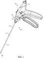
Figure 1 is one embodiment of the surgical access port assembly of the present invention connected to the needlescopic surgical instrument.Figure 2 is a perspective view of an embodiment of the surgical access port assembly of the present invention.Figure 3 is a view of an embodiment of the surgical access port assembly of the present invention looking inward from the hub.Figure 4 is a side view of an embodiment of the surgical access port of the present invention.Figure 5 is an embodiment of the surgical access port of the present invention including an optional cap.Figure 6 is a top view of an embodiment of the surgical access port of the present invention connected to a needlescopic lumen.Figure 7 is an exploded view of an embodiment of the surgical access port assembly of the present invention connected to the needlescopic surgical instrument.Figures 8A through 8E are an exemplary method of use.- Reference will now be made to the drawings wherein like reference numerals identify similar structural features or aspects of the subject invention. For purposes of explanation and illustration, and not limitation, exemplary embodiments of a surgical access port assembly in accordance with the invention, or aspects thereof, are shown in
Figures 1 through 8E . The surgical assembly of the invention is a low cost,easy to manufacture, surgical access port assembly, which can be used, for example,during minimally invasive surgical procedures to reduce trauma to a patient. - Examples of minimally invasive surgical assemblies and related equipment are described in
U.S. Patent No. 7,766,937 to Ravikumar ,U.S. Patent No.8,230,863 to Ravikumar et al. ,U.S. Patent No. 8,313,507 to Ravikumar ,U.S. Patent No.8,133,255 to Ravikumar et al. ,U.S. Patent Application No. 1 1/685,522 to Ravikumar etal U.S. Patent Pub. No. 2007/02501 12 ),U.S. Patent Application No. 12/503,035 to Ravikumar (published asU.S. Patent Pub. No. 2010/0016884 ),U.S. Patent Application No. 12/689,352 to Ravikumar et al (published asU.S. Patent Pub. No. 2010/0292724 ),U.S. Patent Application No. 1 1/610,746 to Ravikumar et al U.S. Patent Pub. No. 2007/0282170 ), andU.S. Patent Application No. 12/689,352 to Ravikumar et al. (published asU.S. Patent Pub. No. 2010/0292724 ). - The present disclosure includes an exchanger surgical
access port assembly 100, which includes a surgical access port including a cannula and a hub. The inventivesurgical access port 100 is connected to a laparoscopic instrument having an elongated cannula, optionally including a needle (a needlescopic surgical instrument), such that the surgical access port is placed over cannula and thus does not require an obturator as the needle of the surgical instrument pierces the patient's skin and thereafter thesurgical access port 100 is moved down the cannula and inserted into the incision at the surgical site. - The surgical
access port assembly 100 includes acannula 100 with a diameter of about 1 mm to about 5 mm (+ 20%) thereby reducing trauma to the patient and eliminates the need for a larger incision point or for a series of small incision cuts through the various layers of fascia. The diameter of thecannula 100 is preferably less than about 3 mm, preferably between about 2.0 mm to about 2.96 mm. The incision point may be about 4 mm or less depending on the diameter of the distal tip portion of theneedle 209 of the laparoscopicsurgical instrument 200. The inventive surgical access port assembly has a smaller diameter and thus a smaller incision point and working area within the body wall of the patient. Thus the potential scarring area is smaller and there is potential for reduced complications. Further, as the diameter of the cannula is smaller there is reduced tearing of the skin when the surgical access port assembly is angled during use in surgery when a surgical instrument is within the surgical access port. The smaller the diameter and surgical working area within the body wall (not the body cavity itself) the better during the surgery. The smaller diameter should not affect the working area within the body cavity during the surgery thus maintaining the effectiveness and efficacy of the surgical process. The smaller diameter of the cannula of the surgical access port assembly is particularly useful in pediatric patients, geriatric patients and other patients where the body wall may be negatively affected by a larger incision point and port access area. - Referring now to
Figures 1 through 5 , an embodiment of the present invention is shown of a surgicalaccess port assembly 100. Thesurgical access port 100 has an elongatedcannula 110. Thedistal end 117 of theelongated cannula 110 may be blunt or beveled. Theelongated cannula 110 has a hollow shaft, acannula shaft 115, through which surgical instruments may enter when the surgical access port is in use. Theelongated cannula 110 has a proximal end connected to ahub 120. Thehub 120 has a diameter, which expands outwardly from the proximal end of theelongated cannula 110. Thehub 120 includes aportion 122 connected to the proximal end of theelongated cannula 110, anouter ring portion 125 which may be used for manual manipulation of thesurgical access port 100, and an open end taperedportion 126 of the hub with a diameter exceeding that of theelongated cannula 110. Theopen end portion 126 of thehub 120 is capable of providing access for surgical instruments and devices during surgery. Further theopen end portion 126 of thehub 120 may be connected to a portion ofproximal end 203 of asurgical instrument cannula 207. The connection of thehub 120 of the inventivesurgical access port 100 to the surgical instrument'shub 203 may be via friction, force, or snapped onto thehub 203. - The
surgical access port 100 may be made of various materials such as rigid materials such as metals, for example stainless steel, as well as rigid plastics such as liquid crystal polymer or polycarbonate, glass-filled polycarbonate, or the like. The material should be compatible with the human fascia, body wall and any body cavity into which it is inserted so as to prevent or reduce any allergic reaction by the patient upon insertion. Optionally, thesurgical access port 100 may be covered on the outside or even within thecannula shaft 117 with an insulating material (not shown) to prevent electrical current transfer to the patient, for instance upon inadvertent contact with an electrical surgical apparatus such as a monopolar or bipolar surgical instrument. The insulating material may be a plastic shrink wrap or any other insulating materials such as plastics, polymers, elastomers and the like, and combinations thereof. - Turning to
Figures 2 through 5 , thehub 120 of the surgical access port100 has an inner portion including at least one inner ring 118, shown inFigures 3 and4 as one embodiment of at least threeinner rings surgical access port 100 to asurgical instrument 200 or other device over such instrument'scannula 207. Optionally, one of the inner rings 118 may be an O-ring made of a compressible material so as to seal a portion of thesurgical access port 100 and deter the leakage of gas during surgical insufflation. For instance the O-ring may be made of rubbers, foams, plastics, silicones, fluorocarbons, polymers, elastomers, nitriles and the like, including combinations thereof. - The
surgical access port 100 may also include acap 150, as seen inFigure 5 , connected to thehub 120 via acap tether 160 and aring 170 on thehub 120. In use, once thesurgical access port 100 is inserted into the patient's body, during surgery there may be a time when the original incision surgical instrument is not being employed in the patient's body and it is withdrawn such that thesurgical access port 100 is not in use, therefore thecap 150 may be inserted into theopen end portion 126 of thehub 120 and the opening sealed for anti-contamination reasons and also resulting in less gas leakage during surgical insufflation. For instance, when one surgical instrument is removed and before the next is exchanged or inserted thecap 150 may be employed. Thereafter at any time during the surgery when the exchanger surgical access port does not include any surgical instrument within theelongated cannula 110 thecap 150 may be used. Figures 6 and 7 show another embodiment of the present invention wherein thesurgical access port 100 is connected to aneedle lumen 400 having alumen shaft 420 and an end effector such as aneedle 410, whichneedle lumen 400 may be inserted into a resposable handgrip surgical instrument or any other surgical instrument. Theneedle lumen 400 is inserted into an aperture of thesurgical access port 100 via the open end taperedportion 126 of thehub 120 through to theshaft 117 of theelongated cannula 110. As seen inFigure 7 , thesurgical access port 100 is thus connected to theneedle lumen 400 in this embodiment by friction and light compression of theinner rings hub 120 against ahub 430 of theneedle lumen 400. Other connection or securing means may be used in other embodiments.- In use, the needle of the needlescopic surgical instrument is used to penetrate the patient's fascia, the exchanger surgical
access port assembly 100 is moved in an axial movement down the needle lumen via manual manipulation of theouter ring 125 and thesurgical access port 100 is inserted into the patient's fascia and through the body wall. Generally, thesurgical access port 100 is attached to the lumen of a percutaneous instrument, or single needle lumen, by pressure, friction or snapping on to the back of the exposed lumen. Thesurgical access port 100 is then advanced along the lumen, away from the percutaneous instrument, into the patient's fascia, through the body wall and into a body cavity when and as required and will remain in the body cavity as the lumen is removed and such initial instrument may be exchanged and replaced with a different instrument. - Further disclosed is a surgical instrument including a
surgical access port 100. For instance, a needlescopic instrument having a lumen with a diameter of less than about 3 mm, preferably between about 2.3 mm to about 2.96 mm, with the lumen including a needle and optionally additional end-effectors such as jaws, dissectors, scissors, spatulas, cauterizers and the like including any known or later developed end-effectors. The exchanger surgicalaccess port assembly 100 can be placed around the lumen that in normal working of the surgical instrument is outside of the patient, but can be unattached, and inserted into the patient's fascia, providing a guide for additional percutaneous instruments to be exchanged and inserted therein. - The following refers to
Figures 8A through 8E and describe one method in which thesurgical access port 100 could be utilized when in surgery wherein thesurgical access port 100 is connected to a surgical instrument. In such an example the percutaneoussurgical instrument 200 could be pre-packaged withsurgical access port 100 connect in place or thesurgical access port 100 could be separate and is placed ontopercutaneous instrument 200 by the user prior to inserting the distal end of alumen 207, or aneedle 209, of the instrument into the patient's fascia,body wall 300 andbody cavity 350 as seen inFigure 8A . Next the percutaneous instrument shaft traverses thebody wall 300 and the instrument working end is used as an operative instrument. At some time the surgeon withdraws thesurgical instrument 200 as shown inFigure 8C . Then thesurgical access port 100 is used by the surgeon to insert a different instrument into the same position as the original instrument. As seen inFigure 8B , thesurgical access port 100 is advanced over the instrument shaft, or lumen, into thebody wall 300 and into abody cavity 350. The surgeon may then employ thesurgical instrument 200 and engaged the end effectors, in this example shown asgraspers 210. Thereafter as shown inFigure 8C the original instrument is removed from the body and is independent from thesurgical access port 100. At this point in the method thesurgical access port 100 is left in thebody cavity 350 as seen inFigure 8D . Thebody cavity 350 is therefore accessible for various surgical instruments via thesurgical access port 100. Optionally, if included, acap 150 on thehub 120 of thesurgical access port 100 may be inserted to seal thebody cavity 350 opening accessible through thesurgical access port 100. At a later time during the surgery a new instrument 600 (not shown) is exchanged and inserted into thesurgical access port 100 as seen inFigure 8E with thecannula 607 and theneedle end 609 being set for insertion into thesurgical access port 100 via thehub opening 126. A number of instruments may be exchanged and access thebody cavity 350 via thesurgical access port 100 throughout the surgery. In this example the further surgical instrument is shown with aneedle tip 609 but also could be any known end-effector such as a grasper, dissector, spatula, scissors and the like including any known or later developed end-effectors and in other examples the further surgical instrument could be a specimen retrieval bag and other known or later developed surgical instruments. Once the surgery is complete thesurgical access port 100 may be removed manually, or may be slid back up the last instrument's shaft or lumen (i.e., 507), connected onto the back of said instrument's lumen, and removed from the patient'sbody cavity 350, back through thebody wall 300 and out of the patient's fascia. Optionally, based on the smaller incision point in the body wall and smaller diameter of the cannula of the inventive surgical access port assembly, the surgeon may forgo the step of suturing the incision point once the surgical access port assembly is removed, resulting in a faster surgical time and reduced scarring to the patient's facia. - Further advantages of the surgical
access port assembly 100 of the present invention include retention of abdominal pressure during an abdominal surgery. Also the inventive device when in use during a surgery may be self- sealing without compromising insufflation pressure. While not being bound by theory, it is opined that dynamic friction between the outer edge of thesmall diameter cannula 110 and the patient's fascia andbody wall 300 result in minimal gas leakage during insufflation. Thus in use thesurgical access assembly 100 of the present invention has a smaller diameter smaller incision point, better angle for surgical instrument access into the body cavity, while still maintaining sufficient insufflation. The absence of a sealing valve and sealing mechanism results in lower friction, which in turn may improve precision during the surgery. Such improved precision also reduces the surgical time and duration of the surgery which in turn improves surgical recovery by the patient and may reduce surgical complications and scarring. - Unlike typical trocars, the inventive
surgical access port 100 would be attached to the back end of the percutaneous instrument and would only be slid down the shaft of the instrument into the patient's body to provide re-access to the same site location if the percutaneous instrument were to be removed or exchanged. While trocars are independently inserted in to the body cavity, thesurgical access port 100 differs as it is slid into the body cavity over an instrument pre-inserted into the body wall. - In one example the
surgical access port 100 and percutaneous surgical instrument could come packaged as a kit, whereby thesurgical access port 100 is placed onto and snapped onto the lumen of the surgical instrument. It is also envisioned where thesurgical access port 100 would be packaged separately, as a stand-alone product and is utilized whenever needed. - The following benefits, structure, and advantages are also contemplated by the present invention: improved surgical precision, reduced surgical time resulting in reduced trauma to the patient and possibly less scarring, reduced recovery time, less pain, easier angling, easier handling by the user of a surgical instrument inserted into the surgical access port assembly during surgery, and other benefits.
- The systems of the present invention, as described above and shown in the drawings, provide for minimally invasive surgical assemblies including exchanger surgical access port assemblies with superior properties including ease of assembly, use and operation. While the apparatus of the subject invention have been shown and described with reference to preferred embodiments, those skilled in the art will readily appreciate that changes and/or modifications may be made thereto without departing from the scope of the subject invention.
Claims (8)
- A surgical access port assembly (100) capable of attachment to a surgical instrument comprising a hollow cannula (110) and a tapered hub (120) wherein:the hollow cannula defines an interior shaft (115) extending longitudinally therethrough having a diameter of less than 3 mm; andthe tapered hub is provided on a proximal end of the hollow cannula, the tapered hub having an inner open tapered portion defining at least one inner ring (118) configured to attach the surgical instrument via compression of the at least one inner ring.
- A surgical access port assembly according to Claim 1, wherein the hollow cannula has a distal end that is blunt.
- A surgical access port assembly according to Claim 1, wherein the hollow cannula has a distal end that is sharp.
- A surgical access port assembly according to one of claims 1 to 3, wherein the at least one inner ring is comprised of three inner rings (118A, 118B, 118C), and each of the three inner rings are configured to secure the surgical access port to the surgical instrument and to seal a portion of the surgical access.
- A surgical access port assembly according to Claim 4, wherein the at least one of the three inner rings is an O-ring.
- A surgical access port assembly according to one of claims 1 to 5, further comprising a cap (150) that seals the tapered hub.
- A surgical access port assembly according to claim 1, further comprising a surgical instrument (200),
wherein the surgical instrument defines a lumen (207, 400), and the surgical instrument has a needle tip (209, 410) on a distal end and a handle assembly (205) on a proximal end. - A surgical access port asssembly according to claim 5, wherein the O-ring is made of rubbers, foams, plastics, silicones, fluorocarbons, polymers, elastomers, and/or nitriles.
Applications Claiming Priority (2)
| Application Number | Priority Date | Filing Date | Title |
|---|---|---|---|
| US201462024999P | 2014-07-15 | 2014-07-15 | |
| PCT/US2014/056456WO2015047886A1 (en) | 2013-09-18 | 2014-09-19 | Exchanger surgical access port assembly and methods of use |
Publications (3)
| Publication Number | Publication Date |
|---|---|
| EP3071131A1 EP3071131A1 (en) | 2016-09-28 |
| EP3071131A4 EP3071131A4 (en) | 2016-12-21 |
| EP3071131B1true EP3071131B1 (en) | 2019-02-27 |
Family
ID=55073570
Family Applications (3)
| Application Number | Title | Priority Date | Filing Date |
|---|---|---|---|
| EP14849207.7AActiveEP3071131B1 (en) | 2014-07-15 | 2014-09-19 | Exchanger surgical access port assembly |
| EP15822363.6AActiveEP3169257B1 (en) | 2014-07-15 | 2015-07-14 | Exchanger surgical access port assembly |
| EP20161377.5AActiveEP3682826B1 (en) | 2014-07-15 | 2015-07-14 | Locking mechanism for surgical access port |
Family Applications After (2)
| Application Number | Title | Priority Date | Filing Date |
|---|---|---|---|
| EP15822363.6AActiveEP3169257B1 (en) | 2014-07-15 | 2015-07-14 | Exchanger surgical access port assembly |
| EP20161377.5AActiveEP3682826B1 (en) | 2014-07-15 | 2015-07-14 | Locking mechanism for surgical access port |
Country Status (6)
| Country | Link |
|---|---|
| US (3) | US10368907B2 (en) |
| EP (3) | EP3071131B1 (en) |
| JP (2) | JP6400682B2 (en) |
| CN (2) | CN105592809B (en) |
| CA (2) | CA2955040C (en) |
| WO (1) | WO2016011023A1 (en) |
Families Citing this family (26)
| Publication number | Priority date | Publication date | Assignee | Title |
|---|---|---|---|---|
| EP2986233B1 (en) | 2013-04-16 | 2022-06-15 | Teleflex Medical Incorporated | Needlescopic instrument with reusable handle and detachable needle assembly |
| CA2924097C (en) | 2013-09-18 | 2018-03-06 | Teleflex Medical Incorporated | Exchanger surgical access port assembly |
| EP3071131B1 (en) | 2014-07-15 | 2019-02-27 | Teleflex Medical Incorporated | Exchanger surgical access port assembly |
| JP6871279B2 (en)* | 2016-07-11 | 2021-05-12 | コンメッド コーポレーション | Cannula assembly for robot-assisted pressure-controlled laparoscopic surgery |
| WO2018023149A1 (en)* | 2016-08-04 | 2018-02-08 | Macquarie University | Laparoscopic guide |
| WO2018064673A1 (en)* | 2016-09-30 | 2018-04-05 | Reish Timothy G | Devices and methods for use in performing arthroscopic total shoulder replacement |
| CN113729889B (en)* | 2016-11-22 | 2025-03-07 | 阿尔弗雷德医疗集团 | Surgical system and method of use |
| US20200085524A1 (en)* | 2017-05-24 | 2020-03-19 | Covidien Lp | Surgical sleeve for robotic systems |
| CN109512473A (en)* | 2017-09-20 | 2019-03-26 | 史军 | Medical Devices with visual puncturing device |
| ES2976202T3 (en) | 2018-01-10 | 2024-07-26 | The Provost Fellows Scholars And Other Members Of Board Of Trinity College Dublin | System for sealing a channel in tissue |
| WO2019180154A1 (en)* | 2018-03-21 | 2019-09-26 | The Provost, Fellows, Scholars And Other Members Of Board Of Trinity College Dublin | A stabiliser |
| TWI695703B (en)* | 2019-04-26 | 2020-06-11 | 李乾坤 | Endoscope holding assembly and holder |
| US12213699B2 (en) | 2020-05-01 | 2025-02-04 | Cilag Gmbh International | Threaded cannula depth limiter |
| US11559329B2 (en) | 2020-05-01 | 2023-01-24 | Cilag Gmbh International | Balancing feature for reusable trocar |
| US11986215B2 (en) | 2020-05-01 | 2024-05-21 | Cilag Gmbh International | Universal size multi-walled elastomer cannula depth limiter |
| US12042342B2 (en) | 2020-05-01 | 2024-07-23 | Cilag Gmbh International | Stabilizer for surgical shafts or cannulas |
| US11633211B2 (en) | 2020-05-01 | 2023-04-25 | Cilag Gmbh International | Pinch to release cannula depth limiter |
| US11974773B2 (en) | 2020-05-01 | 2024-05-07 | Cilag Gmbh International | Latchless obturator with interference fit feature |
| US11980392B2 (en) | 2020-05-01 | 2024-05-14 | Cilag Gmbh International | Pinch-to-clamp cannula depth limiter |
| US12402912B2 (en) | 2020-05-01 | 2025-09-02 | Cilag Gmbh International | Multi-diameter cannula depth limiter |
| US11712267B2 (en) | 2020-05-01 | 2023-08-01 | Cilag Gmbh International | Tilting tang cannula depth limiter |
| US11980393B2 (en) | 2020-05-01 | 2024-05-14 | Cilag Gmbh International | Two-piece separable obturator |
| US12035941B2 (en) | 2020-05-01 | 2024-07-16 | Cilag Gmbh International | Airflow channels and patterns in lumen for cannula |
| WO2024178416A1 (en)* | 2023-02-24 | 2024-08-29 | Matchstick Llc | Systems, methods, and apparatus for localizing and accessing implanted port |
| EP4437982A1 (en)* | 2023-03-31 | 2024-10-02 | Mölnlycke Health Care AB | A trocar fixation assembly |
| CN116549069B (en)* | 2023-04-25 | 2024-07-02 | 苏州新云医疗设备有限公司 | Medical stabilizer |
Family Cites Families (60)
| Publication number | Priority date | Publication date | Assignee | Title |
|---|---|---|---|---|
| JPS58133348U (en)* | 1982-03-03 | 1983-09-08 | メデイキツト株式会社 | catheter |
| US4655750A (en)* | 1985-11-22 | 1987-04-07 | Manresa, Inc. | Closed system catheter with guide wire |
| JPH0215159A (en) | 1988-07-01 | 1990-01-18 | Mitsubishi Metal Corp | Production of cutting made of surface-treated cermet |
| JPH048918Y2 (en) | 1988-07-15 | 1992-03-05 | ||
| US5201742A (en)* | 1991-04-16 | 1993-04-13 | Hasson Harrith M | Support jig for a surgical instrument |
| US5658272A (en)* | 1992-09-15 | 1997-08-19 | Hasson; Harrith M. | Surgical instrument support and method of using the same |
| US5282800A (en) | 1992-09-18 | 1994-02-01 | Edward Weck, Inc. | Surgical instrument |
| US5413561A (en)* | 1993-05-13 | 1995-05-09 | Cathco, Inc. | Guiding catheter with sealing cap system for reducing blood loss when inserting guiding catheters |
| US5425376A (en)* | 1993-09-08 | 1995-06-20 | Sofamor Danek Properties, Inc. | Method and apparatus for obtaining a biopsy sample |
| US5456673A (en) | 1994-03-23 | 1995-10-10 | Stryker Corporation | Locking cannula for endoscopic surgery |
| US5454790A (en) | 1994-05-09 | 1995-10-03 | Innerdyne, Inc. | Method and apparatus for catheterization access |
| US5505710A (en)* | 1994-08-22 | 1996-04-09 | C. R. Bard, Inc. | Telescoping probe |
| US5626597A (en)* | 1995-02-21 | 1997-05-06 | United States Surgical Corporation | Percutaneous introducer |
| WO1997014457A1 (en)* | 1995-10-18 | 1997-04-24 | Stouder Albert E Jr | Adjustable length cannula and trocar |
| US5868714A (en) | 1996-09-16 | 1999-02-09 | Endoscopic Concepts, Inc. | Trocar reducer system |
| US6159224A (en) | 1996-11-27 | 2000-12-12 | Yoon; Inbae | Multiple needle suturing instrument and method |
| US5759188A (en) | 1996-11-27 | 1998-06-02 | Yoon; Inbae | Suturing instrument with rotatably mounted needle driver and catcher |
| US6197002B1 (en)* | 1997-12-10 | 2001-03-06 | Phillips Plastics Corporation | Laparoscopic tool and method |
| US20030130693A1 (en)* | 1999-05-18 | 2003-07-10 | Levin John M. | Laparoscopic/thorascopic insertion caps |
| US6224569B1 (en)* | 1999-09-24 | 2001-05-01 | Becton, Dickinson And Company | Compact needle point shield |
| US6336914B1 (en) | 2000-01-13 | 2002-01-08 | Gillespie, Iii Richard D. | Releasable interlock assembly having axial and rotational engagement |
| DE50101193D1 (en)* | 2001-06-19 | 2004-01-29 | Storz Karl Gmbh & Co Kg | Access cannula for endoscopic operations, especially for arthroscopy |
| US20040111061A1 (en)* | 2002-11-12 | 2004-06-10 | Diana Curran | Trocar having an inflatable cuff for maintaining an insufflated abdominal cavity during an open laparaoscopy procedure |
| CA2522617C (en)* | 2003-04-25 | 2012-04-17 | Tyco Healthcare Group Lp | Surgical access apparatus |
| US7150749B2 (en) | 2003-06-13 | 2006-12-19 | Sherwood Services Ag | Vessel sealer and divider having elongated knife stroke and safety cutting mechanism |
| US7479150B2 (en) | 2003-09-19 | 2009-01-20 | Tyco Healthcare Group Lp | Trocar insertion apparatus |
| AU2004216609B2 (en) | 2003-09-30 | 2010-08-12 | Ethicon Endo-Surgery, Inc. | Rotational latching system for a trocar |
| US7329233B2 (en)* | 2004-10-05 | 2008-02-12 | Tyco Healthcare Group Lp | Surgical system for laparoscopic surgery |
| US8113548B2 (en) | 2005-06-30 | 2012-02-14 | Ti Group Automotive Systems, Llc | Quick connector for high pressure applications |
| US20070093755A1 (en)* | 2005-09-23 | 2007-04-26 | Koos David R | Cannula handle and storage system |
| EP1933733A2 (en)* | 2005-10-14 | 2008-06-25 | Applied Medical Resources Corporation | Surgical access port |
| US8080004B2 (en) | 2005-10-26 | 2011-12-20 | Earl Downey | Laparoscopic surgical instrument |
| US20070162066A1 (en)* | 2006-01-10 | 2007-07-12 | Lyon Thomas R | Clear view cannula |
| US8313507B2 (en) | 2006-03-13 | 2012-11-20 | Mini-Lap Technologies, Inc. | Minimally invasive rake retractor and method for using same |
| US9486238B2 (en) | 2006-03-13 | 2016-11-08 | Teleflex Medical Incorporated | Minimally invasive surgical clamps, assemblies and methods |
| AU2007226579B2 (en) | 2006-03-13 | 2013-03-14 | Minilap Technologies, Inc. | Minimally invasive surgical assembly and methods |
| US8133255B2 (en) | 2006-03-13 | 2012-03-13 | Mini-Lap Technologies, Inc. | Minimally invasive surgical assembly and methods |
| US7766937B2 (en) | 2006-03-13 | 2010-08-03 | Mini-Lap Technologies, Inc. | Minimally invasive surgical assembly and methods |
| US8230863B2 (en) | 2006-05-30 | 2012-07-31 | Mini-Lap Technologies, Inc. | Platform for fixing surgical instruments during surgery |
| US20070282170A1 (en) | 2006-05-30 | 2007-12-06 | Sundaram Ravikumar | Rake Retractor and Needle Assembly for Minimally Invasive Surgical Applications |
| US20080215078A1 (en) | 2007-01-31 | 2008-09-04 | Bennett Michael D | Surgical blade and trocar system |
| JP5105939B2 (en)* | 2007-04-06 | 2012-12-26 | 株式会社八光 | Medical insertion guide device |
| US20090247900A1 (en)* | 2008-03-25 | 2009-10-01 | Brian Zimmer | Push button adjustable spacer |
| US8956351B2 (en) | 2008-04-09 | 2015-02-17 | Teleflex Medical Incorporated | Minimally invasive surgical needle and cauterizing assembly and methods |
| US8636686B2 (en)* | 2008-04-28 | 2014-01-28 | Ethicon Endo-Surgery, Inc. | Surgical access device |
| JP5464872B2 (en) | 2009-03-06 | 2014-04-09 | 株式会社トップ | forceps |
| IT1395219B1 (en) | 2009-05-19 | 2012-09-05 | Ab Medica Spa | SHUTTER FOR TROCAR AND ITS TROCAR. |
| US9326757B2 (en)* | 2009-12-31 | 2016-05-03 | Teleflex Medical Incorporated | Surgical instruments for laparoscopic aspiration and retraction |
| US20110196205A1 (en)* | 2010-02-05 | 2011-08-11 | Tyco Healthcare Group Lp | Surgical portal locking system |
| US9113862B2 (en) | 2010-09-30 | 2015-08-25 | Ethicon Endo-Surgery, Inc. | Surgical stapling instrument with a variable staple forming system |
| JP5782267B2 (en)* | 2011-02-16 | 2015-09-24 | 株式会社トップ | Trocar's outer tube |
| US20120277576A1 (en) | 2011-04-26 | 2012-11-01 | Chun Kee Lui | Echogenic infusion port catheter |
| JP2013106771A (en) | 2011-11-21 | 2013-06-06 | Olympus Corp | Medical treatment device, and neurostimulation electrode indwelling system |
| JP5999415B2 (en) | 2012-06-01 | 2016-09-28 | 株式会社ジェイ・エム・エス | Indwelling needle device |
| US10058343B2 (en) | 2013-03-14 | 2018-08-28 | Covidien Lp | Systems for performing endoscopic procedures |
| JP6201035B2 (en) | 2013-04-16 | 2017-09-20 | テレフレックス メディカル インコーポレイテッド | Minimally invasive surgical assembly and method |
| EP2986233B1 (en) | 2013-04-16 | 2022-06-15 | Teleflex Medical Incorporated | Needlescopic instrument with reusable handle and detachable needle assembly |
| EP3071131B1 (en) | 2014-07-15 | 2019-02-27 | Teleflex Medical Incorporated | Exchanger surgical access port assembly |
| WO2016022789A1 (en) | 2014-08-07 | 2016-02-11 | Teleflex Medical Incorporated | Surgical instrument electrodes and methods of use |
| EP3179946B1 (en) | 2014-08-13 | 2020-07-08 | Teleflex Medical Incorporated | Surgical instrument electrodes |
- 2014
- 2014-09-19EPEP14849207.7Apatent/EP3071131B1/enactiveActive
- 2014-09-19JPJP2016515483Apatent/JP6400682B2/enactiveActive
- 2014-09-19CNCN201480051800.4Apatent/CN105592809B/enactiveActive
- 2015
- 2015-07-14JPJP2017502604Apatent/JP6411626B2/enactiveActive
- 2015-07-14EPEP15822363.6Apatent/EP3169257B1/enactiveActive
- 2015-07-14CNCN201580042756.5Apatent/CN106659521B/enactiveActive
- 2015-07-14CACA2955040Apatent/CA2955040C/ennot_activeExpired - Fee Related
- 2015-07-14EPEP20161377.5Apatent/EP3682826B1/enactiveActive
- 2015-07-14WOPCT/US2015/040371patent/WO2016011023A1/enactiveApplication Filing
- 2015-07-14USUS14/798,987patent/US10368907B2/enactiveActive
- 2015-07-14CACA3079418Apatent/CA3079418C/enactiveActive
- 2019
- 2019-06-19USUS16/445,698patent/US11627984B2/enactiveActive
- 2023
- 2023-04-17USUS18/135,302patent/US20230248389A1/enactivePending
Also Published As
| Publication number | Publication date |
|---|---|
| CN105592809A (en) | 2016-05-18 |
| EP3071131A1 (en) | 2016-09-28 |
| US11627984B2 (en) | 2023-04-18 |
| CN106659521B (en) | 2020-08-18 |
| JP2017527331A (en) | 2017-09-21 |
| EP3071131A4 (en) | 2016-12-21 |
| EP3169257B1 (en) | 2020-03-18 |
| CA2955040A1 (en) | 2016-01-21 |
| US20160015423A1 (en) | 2016-01-21 |
| JP6400682B2 (en) | 2018-10-03 |
| JP2016534763A (en) | 2016-11-10 |
| EP3682826A1 (en) | 2020-07-22 |
| CA3079418A1 (en) | 2016-01-21 |
| EP3169257A1 (en) | 2017-05-24 |
| US20190298408A1 (en) | 2019-10-03 |
| US10368907B2 (en) | 2019-08-06 |
| CA2955040C (en) | 2020-09-15 |
| EP3169257A4 (en) | 2018-02-14 |
| CA3079418C (en) | 2023-01-03 |
| JP6411626B2 (en) | 2018-10-24 |
| CN106659521A (en) | 2017-05-10 |
| EP3682826B1 (en) | 2024-12-25 |
| CN105592809B (en) | 2019-09-06 |
| WO2016011023A1 (en) | 2016-01-21 |
| US20230248389A1 (en) | 2023-08-10 |
Similar Documents
| Publication | Publication Date | Title |
|---|---|---|
| EP3071131B1 (en) | Exchanger surgical access port assembly | |
| EP2138106B1 (en) | Multi lumen access port | |
| EP2277464A1 (en) | Surgical port and frangible introducer assembly | |
| US20130225932A1 (en) | Multi-portion wound protector | |
| EP2316360A1 (en) | Radially expandable access system including trocar seal | |
| US20120123202A1 (en) | Insufflating optical surgical instrument | |
| US10765443B2 (en) | Needlescopic scissor end effector and methods of use | |
| CA2924097C (en) | Exchanger surgical access port assembly | |
| EP2070484A1 (en) | Direct vision port site dissector | |
| AU2019232835A1 (en) | Surgical access device and seal guard for use therewith | |
| US20200268412A1 (en) | Access assembly including flexible cannula | |
| US20210299416A1 (en) | Balloon cannula including a plurality of balloons |
Legal Events
| Date | Code | Title | Description |
|---|---|---|---|
| PUAI | Public reference made under article 153(3) epc to a published international application that has entered the european phase | Free format text:ORIGINAL CODE: 0009012 | |
| 17P | Request for examination filed | Effective date:20160407 | |
| AK | Designated contracting states | Kind code of ref document:A1 Designated state(s):AL AT BE BG CH CY CZ DE DK EE ES FI FR GB GR HR HU IE IS IT LI LT LU LV MC MK MT NL NO PL PT RO RS SE SI SK SM TR | |
| AX | Request for extension of the european patent | Extension state:BA ME | |
| A4 | Supplementary search report drawn up and despatched | Effective date:20161123 | |
| RIC1 | Information provided on ipc code assigned before grant | Ipc:A61M 39/02 20060101ALI20161117BHEP Ipc:A61B 17/34 20060101AFI20161117BHEP Ipc:A61B 17/29 20060101ALI20161117BHEP | |
| DAX | Request for extension of the european patent (deleted) | ||
| STAA | Information on the status of an ep patent application or granted ep patent | Free format text:STATUS: EXAMINATION IS IN PROGRESS | |
| 17Q | First examination report despatched | Effective date:20171030 | |
| GRAP | Despatch of communication of intention to grant a patent | Free format text:ORIGINAL CODE: EPIDOSNIGR1 | |
| STAA | Information on the status of an ep patent application or granted ep patent | Free format text:STATUS: GRANT OF PATENT IS INTENDED | |
| INTG | Intention to grant announced | Effective date:20181002 | |
| GRAS | Grant fee paid | Free format text:ORIGINAL CODE: EPIDOSNIGR3 | |
| GRAA | (expected) grant | Free format text:ORIGINAL CODE: 0009210 | |
| STAA | Information on the status of an ep patent application or granted ep patent | Free format text:STATUS: THE PATENT HAS BEEN GRANTED | |
| AK | Designated contracting states | Kind code of ref document:B1 Designated state(s):AL AT BE BG CH CY CZ DE DK EE ES FI FR GB GR HR HU IE IS IT LI LT LU LV MC MK MT NL NO PL PT RO RS SE SI SK SM TR | |
| REG | Reference to a national code | Ref country code:GB Ref legal event code:FG4D | |
| REG | Reference to a national code | Ref country code:CH Ref legal event code:EP | |
| REG | Reference to a national code | Ref country code:DE Ref legal event code:R096 Ref document number:602014042045 Country of ref document:DE | |
| REG | Reference to a national code | Ref country code:AT Ref legal event code:REF Ref document number:1100214 Country of ref document:AT Kind code of ref document:T Effective date:20190315 | |
| REG | Reference to a national code | Ref country code:IE Ref legal event code:FG4D | |
| REG | Reference to a national code | Ref country code:NL Ref legal event code:MP Effective date:20190227 | |
| REG | Reference to a national code | Ref country code:LT Ref legal event code:MG4D | |
| PG25 | Lapsed in a contracting state [announced via postgrant information from national office to epo] | Ref country code:PT Free format text:LAPSE BECAUSE OF FAILURE TO SUBMIT A TRANSLATION OF THE DESCRIPTION OR TO PAY THE FEE WITHIN THE PRESCRIBED TIME-LIMIT Effective date:20190627 Ref country code:SE Free format text:LAPSE BECAUSE OF FAILURE TO SUBMIT A TRANSLATION OF THE DESCRIPTION OR TO PAY THE FEE WITHIN THE PRESCRIBED TIME-LIMIT Effective date:20190227 Ref country code:NO Free format text:LAPSE BECAUSE OF FAILURE TO SUBMIT A TRANSLATION OF THE DESCRIPTION OR TO PAY THE FEE WITHIN THE PRESCRIBED TIME-LIMIT Effective date:20190527 Ref country code:FI Free format text:LAPSE BECAUSE OF FAILURE TO SUBMIT A TRANSLATION OF THE DESCRIPTION OR TO PAY THE FEE WITHIN THE PRESCRIBED TIME-LIMIT Effective date:20190227 Ref country code:LT Free format text:LAPSE BECAUSE OF FAILURE TO SUBMIT A TRANSLATION OF THE DESCRIPTION OR TO PAY THE FEE WITHIN THE PRESCRIBED TIME-LIMIT Effective date:20190227 Ref country code:NL Free format text:LAPSE BECAUSE OF FAILURE TO SUBMIT A TRANSLATION OF THE DESCRIPTION OR TO PAY THE FEE WITHIN THE PRESCRIBED TIME-LIMIT Effective date:20190227 | |
| PG25 | Lapsed in a contracting state [announced via postgrant information from national office to epo] | Ref country code:BG Free format text:LAPSE BECAUSE OF FAILURE TO SUBMIT A TRANSLATION OF THE DESCRIPTION OR TO PAY THE FEE WITHIN THE PRESCRIBED TIME-LIMIT Effective date:20190527 Ref country code:RS Free format text:LAPSE BECAUSE OF FAILURE TO SUBMIT A TRANSLATION OF THE DESCRIPTION OR TO PAY THE FEE WITHIN THE PRESCRIBED TIME-LIMIT Effective date:20190227 Ref country code:HR Free format text:LAPSE BECAUSE OF FAILURE TO SUBMIT A TRANSLATION OF THE DESCRIPTION OR TO PAY THE FEE WITHIN THE PRESCRIBED TIME-LIMIT Effective date:20190227 Ref country code:IS Free format text:LAPSE BECAUSE OF FAILURE TO SUBMIT A TRANSLATION OF THE DESCRIPTION OR TO PAY THE FEE WITHIN THE PRESCRIBED TIME-LIMIT Effective date:20190627 Ref country code:LV Free format text:LAPSE BECAUSE OF FAILURE TO SUBMIT A TRANSLATION OF THE DESCRIPTION OR TO PAY THE FEE WITHIN THE PRESCRIBED TIME-LIMIT Effective date:20190227 Ref country code:GR Free format text:LAPSE BECAUSE OF FAILURE TO SUBMIT A TRANSLATION OF THE DESCRIPTION OR TO PAY THE FEE WITHIN THE PRESCRIBED TIME-LIMIT Effective date:20190528 | |
| REG | Reference to a national code | Ref country code:AT Ref legal event code:MK05 Ref document number:1100214 Country of ref document:AT Kind code of ref document:T Effective date:20190227 | |
| PG25 | Lapsed in a contracting state [announced via postgrant information from national office to epo] | Ref country code:CZ Free format text:LAPSE BECAUSE OF FAILURE TO SUBMIT A TRANSLATION OF THE DESCRIPTION OR TO PAY THE FEE WITHIN THE PRESCRIBED TIME-LIMIT Effective date:20190227 Ref country code:IT Free format text:LAPSE BECAUSE OF FAILURE TO SUBMIT A TRANSLATION OF THE DESCRIPTION OR TO PAY THE FEE WITHIN THE PRESCRIBED TIME-LIMIT Effective date:20190227 Ref country code:RO Free format text:LAPSE BECAUSE OF FAILURE TO SUBMIT A TRANSLATION OF THE DESCRIPTION OR TO PAY THE FEE WITHIN THE PRESCRIBED TIME-LIMIT Effective date:20190227 Ref country code:SK Free format text:LAPSE BECAUSE OF FAILURE TO SUBMIT A TRANSLATION OF THE DESCRIPTION OR TO PAY THE FEE WITHIN THE PRESCRIBED TIME-LIMIT Effective date:20190227 Ref country code:AL Free format text:LAPSE BECAUSE OF FAILURE TO SUBMIT A TRANSLATION OF THE DESCRIPTION OR TO PAY THE FEE WITHIN THE PRESCRIBED TIME-LIMIT Effective date:20190227 Ref country code:DK Free format text:LAPSE BECAUSE OF FAILURE TO SUBMIT A TRANSLATION OF THE DESCRIPTION OR TO PAY THE FEE WITHIN THE PRESCRIBED TIME-LIMIT Effective date:20190227 Ref country code:EE Free format text:LAPSE BECAUSE OF FAILURE TO SUBMIT A TRANSLATION OF THE DESCRIPTION OR TO PAY THE FEE WITHIN THE PRESCRIBED TIME-LIMIT Effective date:20190227 Ref country code:ES Free format text:LAPSE BECAUSE OF FAILURE TO SUBMIT A TRANSLATION OF THE DESCRIPTION OR TO PAY THE FEE WITHIN THE PRESCRIBED TIME-LIMIT Effective date:20190227 | |
| REG | Reference to a national code | Ref country code:DE Ref legal event code:R097 Ref document number:602014042045 Country of ref document:DE | |
| PG25 | Lapsed in a contracting state [announced via postgrant information from national office to epo] | Ref country code:SM Free format text:LAPSE BECAUSE OF FAILURE TO SUBMIT A TRANSLATION OF THE DESCRIPTION OR TO PAY THE FEE WITHIN THE PRESCRIBED TIME-LIMIT Effective date:20190227 Ref country code:PL Free format text:LAPSE BECAUSE OF FAILURE TO SUBMIT A TRANSLATION OF THE DESCRIPTION OR TO PAY THE FEE WITHIN THE PRESCRIBED TIME-LIMIT Effective date:20190227 | |
| PG25 | Lapsed in a contracting state [announced via postgrant information from national office to epo] | Ref country code:AT Free format text:LAPSE BECAUSE OF FAILURE TO SUBMIT A TRANSLATION OF THE DESCRIPTION OR TO PAY THE FEE WITHIN THE PRESCRIBED TIME-LIMIT Effective date:20190227 | |
| PLBE | No opposition filed within time limit | Free format text:ORIGINAL CODE: 0009261 | |
| STAA | Information on the status of an ep patent application or granted ep patent | Free format text:STATUS: NO OPPOSITION FILED WITHIN TIME LIMIT | |
| 26N | No opposition filed | Effective date:20191128 | |
| PG25 | Lapsed in a contracting state [announced via postgrant information from national office to epo] | Ref country code:SI Free format text:LAPSE BECAUSE OF FAILURE TO SUBMIT A TRANSLATION OF THE DESCRIPTION OR TO PAY THE FEE WITHIN THE PRESCRIBED TIME-LIMIT Effective date:20190227 | |
| PG25 | Lapsed in a contracting state [announced via postgrant information from national office to epo] | Ref country code:TR Free format text:LAPSE BECAUSE OF FAILURE TO SUBMIT A TRANSLATION OF THE DESCRIPTION OR TO PAY THE FEE WITHIN THE PRESCRIBED TIME-LIMIT Effective date:20190227 | |
| PG25 | Lapsed in a contracting state [announced via postgrant information from national office to epo] | Ref country code:MC Free format text:LAPSE BECAUSE OF FAILURE TO SUBMIT A TRANSLATION OF THE DESCRIPTION OR TO PAY THE FEE WITHIN THE PRESCRIBED TIME-LIMIT Effective date:20190227 | |
| REG | Reference to a national code | Ref country code:CH Ref legal event code:PL | |
| PG25 | Lapsed in a contracting state [announced via postgrant information from national office to epo] | Ref country code:LU Free format text:LAPSE BECAUSE OF NON-PAYMENT OF DUE FEES Effective date:20190919 Ref country code:LI Free format text:LAPSE BECAUSE OF NON-PAYMENT OF DUE FEES Effective date:20190930 Ref country code:CH Free format text:LAPSE BECAUSE OF NON-PAYMENT OF DUE FEES Effective date:20190930 Ref country code:IE Free format text:LAPSE BECAUSE OF NON-PAYMENT OF DUE FEES Effective date:20190919 | |
| REG | Reference to a national code | Ref country code:BE Ref legal event code:MM Effective date:20190930 | |
| PG25 | Lapsed in a contracting state [announced via postgrant information from national office to epo] | Ref country code:BE Free format text:LAPSE BECAUSE OF NON-PAYMENT OF DUE FEES Effective date:20190930 | |
| PG25 | Lapsed in a contracting state [announced via postgrant information from national office to epo] | Ref country code:CY Free format text:LAPSE BECAUSE OF FAILURE TO SUBMIT A TRANSLATION OF THE DESCRIPTION OR TO PAY THE FEE WITHIN THE PRESCRIBED TIME-LIMIT Effective date:20190227 | |
| PG25 | Lapsed in a contracting state [announced via postgrant information from national office to epo] | Ref country code:HU Free format text:LAPSE BECAUSE OF FAILURE TO SUBMIT A TRANSLATION OF THE DESCRIPTION OR TO PAY THE FEE WITHIN THE PRESCRIBED TIME-LIMIT; INVALID AB INITIO Effective date:20140919 Ref country code:MT Free format text:LAPSE BECAUSE OF FAILURE TO SUBMIT A TRANSLATION OF THE DESCRIPTION OR TO PAY THE FEE WITHIN THE PRESCRIBED TIME-LIMIT Effective date:20190227 | |
| PG25 | Lapsed in a contracting state [announced via postgrant information from national office to epo] | Ref country code:MK Free format text:LAPSE BECAUSE OF FAILURE TO SUBMIT A TRANSLATION OF THE DESCRIPTION OR TO PAY THE FEE WITHIN THE PRESCRIBED TIME-LIMIT Effective date:20190227 | |
| PGFP | Annual fee paid to national office [announced via postgrant information from national office to epo] | Ref country code:DE Payment date:20240927 Year of fee payment:11 | |
| PGFP | Annual fee paid to national office [announced via postgrant information from national office to epo] | Ref country code:GB Payment date:20240927 Year of fee payment:11 | |
| PGFP | Annual fee paid to national office [announced via postgrant information from national office to epo] | Ref country code:FR Payment date:20240925 Year of fee payment:11 |