EP3070204B1 - Device and method for conveying water from a well - Google Patents
Device and method for conveying water from a wellDownload PDFInfo
- Publication number
- EP3070204B1 EP3070204B1EP16000501.3AEP16000501AEP3070204B1EP 3070204 B1EP3070204 B1EP 3070204B1EP 16000501 AEP16000501 AEP 16000501AEP 3070204 B1EP3070204 B1EP 3070204B1
- Authority
- EP
- European Patent Office
- Prior art keywords
- filter tube
- tube
- well
- blank casing
- blank
- Prior art date
- Legal status (The legal status is an assumption and is not a legal conclusion. Google has not performed a legal analysis and makes no representation as to the accuracy of the status listed.)
- Active
Links
Images


Classifications
- E—FIXED CONSTRUCTIONS
- E02—HYDRAULIC ENGINEERING; FOUNDATIONS; SOIL SHIFTING
- E02D—FOUNDATIONS; EXCAVATIONS; EMBANKMENTS; UNDERGROUND OR UNDERWATER STRUCTURES
- E02D19/00—Keeping dry foundation sites or other areas in the ground
- E02D19/06—Restraining of underground water
- E02D19/10—Restraining of underground water by lowering level of ground water
- E—FIXED CONSTRUCTIONS
- E03—WATER SUPPLY; SEWERAGE
- E03B—INSTALLATIONS OR METHODS FOR OBTAINING, COLLECTING, OR DISTRIBUTING WATER
- E03B3/00—Methods or installations for obtaining or collecting drinking water or tap water
- E03B3/06—Methods or installations for obtaining or collecting drinking water or tap water from underground
- E03B3/08—Obtaining and confining water by means of wells
- E03B3/12—Obtaining and confining water by means of wells by means of vertical pipe wells
- E—FIXED CONSTRUCTIONS
- E03—WATER SUPPLY; SEWERAGE
- E03B—INSTALLATIONS OR METHODS FOR OBTAINING, COLLECTING, OR DISTRIBUTING WATER
- E03B3/00—Methods or installations for obtaining or collecting drinking water or tap water
- E03B3/06—Methods or installations for obtaining or collecting drinking water or tap water from underground
- E03B3/08—Obtaining and confining water by means of wells
- E03B3/16—Component parts of wells
- E03B3/18—Well filters
- Y—GENERAL TAGGING OF NEW TECHNOLOGICAL DEVELOPMENTS; GENERAL TAGGING OF CROSS-SECTIONAL TECHNOLOGIES SPANNING OVER SEVERAL SECTIONS OF THE IPC; TECHNICAL SUBJECTS COVERED BY FORMER USPC CROSS-REFERENCE ART COLLECTIONS [XRACs] AND DIGESTS
- Y02—TECHNOLOGIES OR APPLICATIONS FOR MITIGATION OR ADAPTATION AGAINST CLIMATE CHANGE
- Y02A—TECHNOLOGIES FOR ADAPTATION TO CLIMATE CHANGE
- Y02A20/00—Water conservation; Efficient water supply; Efficient water use
Definitions
- the inventionrelates to a device for conveying water from a well for water retention or lowering in a civil engineering structure, according to the preamble of claim 1.
- the inventionalso relates to a corresponding method for conveying water from a well with such a device.
- Fig. 10a longitudinal sectional view through a conventional device is shown, by means of which water can be conveyed from a well 2.
- the well 2has a bore 4 which, after the device has been introduced, is filled with a special gravel having a predetermined grain size.
- an annular space fill 5is formed, namely in the annular space between an outer peripheral surface of the device and an edge of the bore 4.
- a sound barrier layer 6is provided within the bore 4, at a predetermined axial depth thereof.
- the devicecomprises an elongated slotted tube 8, which is usually made of PVC plastic.
- a plurality of axially extending slots 9are formed in the wall of this slot tube 8, which allow water to enter the slot tube 8 radially from the outside.
- the annular space fill 5serves as a filter for the water flowing in radially from the outside.
- a pump device 18is arranged, which is connected to a connecting line 20.
- This connecting line 20leads through the Slot tube 8 through to a surface, wherein in Fig. 10 for simplification only sections of the connecting line 20 are shown at the very bottom and at the very top.
- a separate level pipe 30is also introduced into the bore 4 of the well 2, by means of which a level of the groundwater, which arises when the pump device 18 is in operation, can be measured.
- the pump device 18can be controlled as a function of the level of the groundwater detected with the level pipe 30.
- the conventional device according to the Fig. 10works in such a way that water from the area of the well, which lies vertically below the clay barrier layer 6, enters the slotted tube 8 radially from the outside. The water then falls or flows within the slotted tube 8 vertically downward in the direction of the pump device 18, as is shown by the vertically downward arrows in FIG Fig. 10 is symbolized within the slotted tube 8.
- Such a flow of water within the slotted tube 8has the disadvantage that the water is enriched with oxygen as a result of swirling, and iron hydroxide is thereby formed. Due to the oxygen dissolved in the water, the machine parts or components through which the pumped water flows regularly cause blockages. This affects, for example, the pump device 18 and the connecting line 20 connected to it.
- the inventionis based on the object of optimizing an apparatus and a method for conveying water from a well for water retention or water lowering in a civil engineering structure with a view to increased economy.
- a deviceis used for conveying or pumping water out of a well for water retention or water lowering in a civil engineering structure, and comprises at least one elongated solid tube which can be introduced vertically into a bore in the well. Furthermore, the device comprises at least one filter tube made of stainless steel, which is designed in the form of a winding wire filter and is connected to a lower side of the solid tube, and a pump device by means of which water, which flows in radially from the outside through the filter tube, can be pumped out.
- a diameter of the filter tubeis chosen to be smaller than a diameter of the full tube.
- a contact areais formed within the solid tube, the pump device being arranged on the contact area.
- the solid tubecan preferably also be made of stainless steel.
- a solid tubeis to be understood as a cylindrical tube which is hollow on the inside and has no openings, recesses or the like in its wall or peripheral surface. To this extent, it is not possible with such a full pipe that water enters radially from the outside through its peripheral surface into the inside of the pipe.
- the inventionis based on the essential finding that at least the filter tube, and preferably also the full tube, are made of stainless steel.
- the stability of the device compared to conventionally known devices, which are mostly made of PVC pipes,is significantly increased and multiple installation and removal in or from well bores is made possible.
- the service life of a device according to the inventioncan be increased considerably, as a result of which the device can be used multiple times on different construction sites.
- the design of the filter tube with a smaller diameter than that of the full tubealso results in an advantageous embodiment of the well bore such that an annular space bed adjacent to the filter tube has a greater radial extension than an annular space bed adjacent to the full tube.
- the contact surface formed within the solid tubeis expediently arranged adjacent to the lower end face of the solid tube, and in the simplest case is formed by a region of the lower end face. This creates a “step” that is used to hold the pump device.
- the pump deviceremains inside the full pipe, namely on the just mentioned contact surface on the lower end face of the full pipe. This advantageously minimizes the assembly effort when handling the device.
- the filter tubein the form of a winding wire filter, it is possible for water to flow radially from the outside into the filter tube, and then to be pumped out of the well axially upward to the surface by the pump device adjoining it.
- the water to be pumped outcan only enter radially from the outside through the filter tube, but not radially from the outside through the full tube.
- the waterflows in an area of the well bore, which is located vertically below a clay barrier layer of the well, along an outer circumferential surface of the solid tube and through an annular layer stratification of the well vertically downward in the direction of the filter tube.
- the water to be pumpedis thus largely conveyed vertically along the outer circumferential surface of the full pipe and then occurs radially from the outside into the filter tube. This ensures a uniform flow of water and at the same time prevents swirling of the water and dissolving oxygen therein, as a result of which the problem of loosening up the pumping device and the pipe elements connected to it no longer exists.
- a device as described aboveis used, water flowing in radially from the outside into the filter tube during operation of the pumping device and then pumped out of the well through the at least one full pipe.
- waterflows vertically downwards through an annular space stratification of the well in the direction of the filter tube before it enters the filter tube radially from the outside.
- a diameter of the filter tubeis smaller than a diameter of the full tube, so that the annulus bed of the well adjacent to the at least one filter tube of the device compared to the annulus bed of the well adjacent to the at least one full tube of the device is a larger radial Extends.
- an axial length section in which the at least one solid tube of the device in the bore of the well runs vertically below its clay barrier layercorresponds to a multiple of the diameter of the solid tube.
- Fig. 1shows a simplified side view of a device 1 according to the invention and its essential components.
- the device 1comprises at least one full tube 10 and at least one filter tube 12 which is connected to a lower end face 16 of the full tube 10.
- the filter tube 12is connected to the full tube 10 shown at the bottom, namely in such a way that there is a hydraulic connection between the interior of the filter tube 12 and the full tube 10. Water can thus flow from the filter tube 12 into the full tube 10.
- Further full pipes 10can be connected or fastened above the full pipe 10 shown at the bottom.
- an entire axial length of the device 1is defined by the plurality of full tubes 10, which are fastened to one another with their end faces, in connection with the filter tube 12, which is connected to the bottom tube 10.
- the device 1comprises a pump device 18, which is arranged within the full pipe 10.
- the pump device 18is connected to a connecting line 20 which is guided through the solid tube 10 to the outside on an upper end face of the device 1.
- a connecting line 20which is guided through the solid tube 10 to the outside on an upper end face of the device 1.
- the filter tube 12has a smaller diameter than the full tube 10 adjoining it.
- a contact surface 22is formed on a lower end face 16 of the full pipe 10, on which the pump device 18 is arranged.
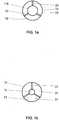
- a plurality of seat blocks 23are mounted on the contact surface 22, on which the pump device 18 rests with its underside. These seat blocks 23 cause water from the filter tube 12 to flow upwards into the full tube 10, the water flowing uniformly around the underside of the pump device 18 and then entering its inlet area 18 E ( Fig. 3 ).
- Fig. 1ashows a simplified sectional view along the line II of FIG Fig. 1 .
- Fig. 1bshows a top view of the contact area 22 within the full pipe 10, the pump device 18 being omitted for simplification. It can be seen that the seat blocks 23 extend radially from the mouth of the filter tube 12 extend to the outer edge of the full pipe 10, and in this respect form a stable support surface for the pump device 18.
- a lifting cap 24 with connecting means 26can be attached to an upper end face 17 of a solid tube 10, which is arranged at the top of the device 1.
- the connecting means 26can be designed, for example, in the form of a ring eye or the like, and serve the purpose that a hook or the like is attached to it. Accordingly, it is possible to hold the device 1 with the lifting cap 24 or to apply a tensile force to the device 1 in its longitudinal axis L, e.g. for pulling the device 1 out of a well bore.
- Radial spacers 28can be attached to an outer circumferential surface of the respective solid tubes 10. The purpose of these radial spacers 28 is explained in detail below.
- Fig. 2shows a fundamentally simplified longitudinal sectional view through a well 2 and a bore 4 of this well, in which the device 1 according to Fig. 1 is introduced.
- the annular space that forms between the outer circumferential surface 11 of the solid tubes 10 and the bore 4is filled with filter gravel, as a result of which an annular space fill 5 is formed.
- a clay barrier layer 6is provided in a predetermined axial depth of the bore 4, which is formed by swelling clay particles.
- the device 1can be inserted centered within the bore 4. It is advantageous here if a level tube 30 is attached to the radial spacers 28 and runs parallel to the solid tubes 10. In this way, the device 1 with its solid tubes 10 and the level tube 30 form a unit which can be inserted together into the bore 4 of the well 2 for the purpose of simplified assembly.
- the connecting line 20is connected to the pump device 18, which runs through the solid tubes 10 upwards and is guided out of the well 2 to a surface. Accordingly, when the pump device 18 is operating, water can be discharged from the well 2 through the connecting line 20.
- the filter tube 12is made of a stainless steel winding wire filter.
- a diameter D 12 of the filter tube 12is smaller than a diameter D 10 of the full tube 10.
- a radial extension of filter gravel within the bore 4 adjacent to the filter tube 12is greater than the radial extension of filter gravel adjacent to the full tube 10.
- FIG Fig. 4The design of the filter tube 12 in the form of a winding wire filter is shown in FIG Fig. 4 shown, which illustrates a simplified cross-sectional view of a wall of the filter tube 12.
- the filter tube 12has a plurality of winding wires 14 along its longitudinal axis L, which are arranged at a distance from one another in parallel.
- the individual winding wires 14are each in a plane E, which is perpendicular to the longitudinal axis L of the device 1, arranged and each running along the circumference of the filter tube 12.
- the winding wires 14are each attached or fastened to support webs 15 which extend parallel to the longitudinal axis L of the device 1.
- Fig. 4only the right part of a filter tube 12 is shown.
- the edge regions of the winding wires 14are designed in such a way that a passage D F between each two adjacent winding wires 14 increases radially inwards.
- the passage D F directed radially inwardhas an opening angle ⁇ of 90 °.
- Such a configuration of the passage D F with a radially inward increasing opening angle ⁇has the result that grains of sand, sediments or the like can only adhere to a small extent or not at all between the winding wires 14 and thereby prevent the filter tube 12 from becoming blocked by such particles is. Accordingly, a uniformly constant and high water throughput is ensured for the filter tube 12 during operation of the device 1.
- the edge regions of opposing winding wires 14can also be designed such that the opening angle of the passage D F formed therebetween takes on values other than 90 °, for example of at least 45 °, more preferably of at least 60 °. In any case, this opening angle ⁇ should increase radially inwards, so that, as explained, the passages D F between the winding wires 14 are not clogged by sediments or the like.
- An advantageous length proportion of the device 1, according to which the filter tube 12 has a comparatively small axial lengthcan further be defined in that the axial length section A F , in which the at least one filter tube is provided, preferably a maximum of ten times (10 times) a maximum of five times (5 times), and further preferably a maximum of twice the value of the diameter D 12 of the filter tube 12.
- a desired minimum throughput of water, which is to flow radially from the outside into the filter tube 12,can be compensated for with a reduced axial length of the filter tube 12 by correspondingly large passages D F between the winding wires 14 of the filter tube 12.
- the device 1can have a plurality of solid tubes 10 along its longitudinal axis L, which are connected to one another at their end faces. In this way, it is possible to implement a large axial length section A V , in which the full pipes 10 are provided, for the device.
- a plurality of solid tubes 10can be connected by a system 100 in which at least one holding element 114 is formed on a tube element 110 on a wall adjacent to its end face. Furthermore, such a system provides a link guide 116 for a second tube element 112, which is formed in the region of a wall of the second tube element 112 and adjacent to its end face.
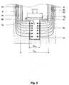
- the pipe elements 110, 112are in the Fig. 5 shown in a side view, namely with their opposite end faces 110 s , 112 s .
- the holding element 114is formed on the wall of the first tubular element 110 adjacent to its end face 110 s , namely on its inner peripheral surface. Accordingly, the holding element 114 is not visible from the outside and in Fig. 5 indicated by dashed lines.
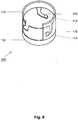
- the second tubular element 112is in the Fig. 6 shown separately in a side view, namely with its end face 112 s .
- the link guide 116is formed in the wall of the second tubular element 112 and has a total of three sections I, II and III.
- the first section Iis open adjacent to the end face 112 s and extends parallel to the longitudinal axis L of the second tubular element 112.
- the second section IIconnects to the first section I. and extends obliquely to the longitudinal axis L of the second tubular element 112.
- the third section IIIadjoins the second section II and extends transversely to the longitudinal axis of the second tubular element 112.
- the link guide 116By forming the link guide 116 in the wall of the second tubular element 112, in a corresponding recess 118 is formed in the wall of this tubular element. Furthermore, the third section III of the link guide 116 comprises a locking trough 120, the function of which is explained in detail below.
- the view after Fig. 5illustrates that the first tubular element 110 has a diameter D 1 on its end face 110 s .
- the second tubular element 112has a diameter D 2 on its end face 112 s .
- the dimensions of the tubular elements 110, 112 on their end facesare selected such that the relationship applies: D 2 ⁇ D 1 . Because the diameter D 2 of the end face 112 s of the second tubular member 112 is selected to be larger than the diameter D 1 of the front face 110 s of the first tubular member 110, the first tube member 110 s can be attached to the second tubular member 112 with its end face 110th This plugging together of the two tubular elements, whereby the first tubular element 110 is mounted on the second tubular element 112, is shown in FIG Fig. 5 symbolized by the arrow M.
- Fig. 7shows the two pipe elements 110, 112 of Fig. 5 in a perspective view.
- Three holding elements 114are formed on the first tubular element 110 on the inner circumferential surface thereof, which are evenly spaced apart along the circumference of the first tubular element 110.
- three link guides 116are likewise provided on the second tubular element 112, namely along the circumference of the second holding element 112 at a uniform distance from one another.
- the arrow Msymbolizes mounting of the first tubular element 110 on the second tubular element 112.
- the two pipe elements 110, 112are initially positioned coaxially with one another, with the first pipe element 110 above the second pipe element, for example 112 is positioned and the holding elements 114 of the first tubular element 110 are each aligned with the first sections I of the respective link guides 116 of the second tubular element 112.
- Starting position of the two tubular elements 110, 112 showncan then be connected in such a way that the first tubular element 110 is moved in the direction of the second tubular element 112 or is lowered onto the second tubular element 112.
- the sequence of assembly of the two tubular elements 110, 112is shown on their end faces.
- the holding elements 114enter the first section I of the respective link guides 116 of the second tubular element 112 ( Fig. 8 ).
- the holding elements 114then automatically pass through the second section II of the respective link guides 116 to their third section III ( Fig. 9 ).
- the holding elements 114are located in the third section III of the link guides 116, further rotation of the tubular elements 110, 112 relative to one another can cause the holding elements 114 to be received in the respective locking troughs 120 and to snap in there.
- the two tubular elements 110, 112are then both axially fixed to one another, that is to say in the direction of their longitudinal axis L, and secured against automatic rotation relative to one another. In this way, a reliable connection of the two pipe elements 110, 112 is ensured on their opposite end faces 110 s , 112 s .
- the positioning of the first holding element 110 as shown in FIG Fig. 9 , according to which the end face 110 s is plugged onto the end face 112 s of the second tubular element 112is in the Fig. 5 additionally indicated by the dashed face 110 s of the first tubular element 110. Furthermore, in the Fig. 5 the different positions of the holding element 114 within the link guide 116 are indicated during assembly of the two tubular elements 110, 112.
- first and second tubular elements 110, 112On the outer peripheral surfaces of the first and second tubular elements 110, 112, locking webs 126 ( Fig. 5 ) be trained. These locking webs 126 are used in conjunction with a tool (not shown) for the purpose that the pipe elements 110, 112 can be rotated relative to one another after the holding elements 114 have reached the third section III of the link guides 116 during assembly, so that then snap the holding elements 114 into the recesses 120 as explained. In this case, a torque about the longitudinal axis L of the tubular elements 110, 112 can be generated by means of a suitable tool and in interaction with the locking webs 126. Furthermore, it may be pointed out that the spacers 28 ( Fig. 1 ) can be positively connected to the locking bars 126, wherein the locking bars 126 can have a suitable groove for this purpose.
- a spacer element in the form of an O-ring 124(cf. Fig. 5 ) arranged between the tubular elements 110, 112, namely within a groove which can form between the tubular elements 110, 112 in the region of their outer peripheral surface.
- This O-ring 124ensures that the tubular elements 110, 112 are at a predetermined distance from one another and are not “on a block”.
- the holding element 114is held within the locking trough 120 and automatic rotation of the two tube elements 110, 112 is prevented relative to one another, so that, as a result, a reliable connection of the two tube elements 110, 112 on their end faces 110 s , 112 s is ensured.
- a loosening of the two pipe elements 110, 112can proceed from the in Fig. 9 shown state in a simple manner that the tubular elements 110, 112 are rotated relative to each other about their longitudinal axis L such that the holding elements 114 disengage from the locking troughs 120.
- the O-ring 124is previously removed from the groove between the two tubular elements, for example with the aid of a suitable tool in the form of a hook or the like. Then, when the tube elements 110, 112 are rotated further, the holding elements slide 114 through the third section III and the second section II of the respective link guides 116 to their first section I.
- the tubular elements 110, 112can move axially, ie along their longitudinal axis L can be moved away from each other. As a result, the holding elements 114 then move outward from the first section I of the respective link guides 116, as a result of which the tubular elements 110, 112 can be completely detached from one another.
- the device 1According to the above explanation, according to which pipe elements 110, 112 can either be connected to one another at their end faces or can also be detached from one another again, it is therefore possible for the device 1 according to the invention to connect a plurality of solid pipes 10 at their end faces to one another for the device 1 to achieve the largest possible axial length section A V. After pulling the device 1 out of the bore 4 of the well 2, the solid tubes 10 can also be detached or disassembled from one another, as explained. This simplifies, for example, the transport of individual solid tubes 10 on vehicles or the like.
- connecting and detaching tube elements 110, 112also applies in the same way to the device 1 according to the invention for connecting a plurality of filter tubes 12 if a correspondingly large axial length section A F in which the filter tube 12 is to be provided, should be necessary for a specific application of the device 1.
- attach the lifting cap 24 according to the above explanation of the system 100to an upper end face 17 of a solid tube or to remove it.
Landscapes
- Engineering & Computer Science (AREA)
- Life Sciences & Earth Sciences (AREA)
- Hydrology & Water Resources (AREA)
- Environmental & Geological Engineering (AREA)
- Health & Medical Sciences (AREA)
- Water Supply & Treatment (AREA)
- Public Health (AREA)
- Paleontology (AREA)
- General Engineering & Computer Science (AREA)
- Structural Engineering (AREA)
- Civil Engineering (AREA)
- Mining & Mineral Resources (AREA)
- General Life Sciences & Earth Sciences (AREA)
- Filtration Of Liquid (AREA)
Description
Translated fromGermanDie Erfindung betrifft eine Vorrichtung zum Fördern von Wasser aus einem Brunnen zur Wasserhaltung oder Wassersenkung bei einem Tiefbau-Bauwerk, nach dem Oberbegriff von Anspruch 1. Die Erfindung betrifft ebenfalls ein entsprechendes Verfahren zum Fördern von Wasser aus einem Brunnen mit einer solchen Vorrichtung.The invention relates to a device for conveying water from a well for water retention or lowering in a civil engineering structure, according to the preamble of
Zur Wasserhaltung oder Wassersenkung bei Tiefbau-Bauwerken ist es bekannt, eine Vorrichtung mit einer Pumpeinrichtung in eine Bohrung einzubringen. Durch den Betrieb der Pumpeinrichtung ist es möglich, Wasser aus dem Erdreich angrenzend an ein Tiefbau-Bauwerk herauszufördern und somit den Grundwasserspiegel entweder zu senken oder auf einem vorbestimmten tiefen Pegel zu halten.For water retention or water lowering in civil engineering structures, it is known to insert a device with a pump device into a bore. The operation of the pump device makes it possible to convey water out of the ground adjacent to a civil engineering structure and thus either to lower the groundwater level or to keep it at a predetermined low level.
In
In einem Bodenabschnitt des Schlitzrohrs 8 einer herkömmlichen Vorrichtung nach der
Parallel zum Schlitzrohr 8 ist in die Bohrung 4 des Brunnens 2 des Weiteren ein separates Pegelrohr 30 eingebracht, mittels dessen ein Pegel des Grundwassers, der sich bei einem Betrieb der Pumpeinrichtung 18 einstellt, gemessen werden kann. In bekannter Weise kann die Pumpeinrichtung 18 in Abhängigkeit des mit dem Pegelrohr 30 erfassten Pegels des Grundwassers angesteuert werden.Parallel to the slotted
Die herkömmliche Vorrichtung nach der
Aus dem Vorlesungsumdruck "
Aus
Aus
Entsprechend liegt der Erfindung die Aufgabe zugrunde, eine Vorrichtung und ein Verfahren zum Fördern von Wasser aus einem Brunnen zur Wasserhaltung oder Wassersenkung bei einem Tiefbau-Bauwerk im Hinblick auf eine erhöhte Wirtschaftlichkeit zu optimieren.Accordingly, the invention is based on the object of optimizing an apparatus and a method for conveying water from a well for water retention or water lowering in a civil engineering structure with a view to increased economy.
Die obige Aufgabe wird durch eine Vorrichtung mit den Merkmalen von Anspruch 1, und durch ein Verfahren mit den Merkmalen von Anspruch 11 gelöst. Vorteilhafte Weiterbildungen der Erfindungen sind in den abhängigen Ansprüchen definiert.The above object is achieved by an apparatus having the features of
Eine erfindungsgemäße Vorrichtung dient zum Fördern bzw. Abpumpen von Wasser aus einem Brunnen zur Wasserhaltung oder Wassersenkung bei einem Tiefbau-Bauwerk, und umfasst zumindest ein längliches Vollrohr, das vertikal in eine Bohrung des Brunnens eingebracht werden kann. Des Weiteren umfasst die Vorrichtung zumindest ein aus Edelstahl hergestelltes Filterrohr, das in Form eines Wickeldrahtfilters ausgebildet ist und an einer unteren Seite des Vollrohrs angeschlossen ist, und eine Pumpeinrichtung, mittels der Wasser, welches radial von außen durch das Filterrohr einströmt, abgepumpt werden kann. Ein Durchmesser des Filterrohrs ist kleiner gewählt als ein Durchmesser des Vollrohrs. Innerhalb des Vollrohrs ist eine Aufstandsfläche ausgebildet, wobei die Pumpeinrichtung auf der Aufstandsfläche angeordnet ist. Vorzugsweise kann auch das Vollrohr aus Edelstahl hergestellt sein.A device according to the invention is used for conveying or pumping water out of a well for water retention or water lowering in a civil engineering structure, and comprises at least one elongated solid tube which can be introduced vertically into a bore in the well. Furthermore, the device comprises at least one filter tube made of stainless steel, which is designed in the form of a winding wire filter and is connected to a lower side of the solid tube, and a pump device by means of which water, which flows in radially from the outside through the filter tube, can be pumped out. A diameter of the filter tube is chosen to be smaller than a diameter of the full tube. A contact area is formed within the solid tube, the pump device being arranged on the contact area. The solid tube can preferably also be made of stainless steel.
Im Sinne der vorliegenden Erfindung darf darauf hingewiesen werden, dass ein Vollrohr als ein zylindrisches Rohr zu verstehen ist, welches innen hohl ausgebildet ist und in seiner Wandung bzw. Umfangsfläche keine Öffnungen, Ausnehmungen oder dergleichen hat. Insoweit ist es bei einem solchen Vollrohr nicht möglich, dass Wasser radial von außen durch dessen Umfangsfläche hindurch in das Innere des Rohrs eintritt.In the sense of the present invention, it should be pointed out that a solid tube is to be understood as a cylindrical tube which is hollow on the inside and has no openings, recesses or the like in its wall or peripheral surface. To this extent, it is not possible with such a full pipe that water enters radially from the outside through its peripheral surface into the inside of the pipe.
Der Erfindung liegt die wesentliche Erkenntnis zugrunde, dass zumindest das Filterrohr, und vorzugsweise auch das Vollrohr, aus Edelstahl hergestellt sind. In dieser Weise wird die Stabilität der Vorrichtung im Vergleich zu herkömmlich bekannten Vorrichtungen, die zumeist aus PVC-Rohren hergestellt sind, wesentlich erhöht und ein mehrfacher Ein- und Ausbau in bzw. aus Brunnenbohrungen ermöglicht. Im Ergebnis kann die Lebensdauer einer erfindungsgemäßen Vorrichtung beträchtlich erhöht werden, wodurch ein mehrfacher Einsatz der Vorrichtung an verschiedenen Baustellen realisiert werden kann.The invention is based on the essential finding that at least the filter tube, and preferably also the full tube, are made of stainless steel. In this way, the stability of the device compared to conventionally known devices, which are mostly made of PVC pipes, is significantly increased and multiple installation and removal in or from well bores is made possible. As a result, the service life of a device according to the invention can be increased considerably, as a result of which the device can be used multiple times on different construction sites.
Durch die Ausbildung des Filterrohrs mit kleinerem Durchmesser als im Vergleich zum Vollrohr ergibt sich auch eine vorteilhafte Ausgestaltung der Brunnenbohrung dahingehend, dass eine Ringraumschüttung angrenzend an das Filterrohr eine größere radiale Erstreckung aufweist als eine Ringraumschüttung angrenzend an das Vollrohr. Somit durchströmt Wasser, welches radial von außen in das Filterrohr eintritt, eine größere Strecke von Filterkies, was zu einer verstärkten Reinigung des Wassers in diesem Bereich führt.The design of the filter tube with a smaller diameter than that of the full tube also results in an advantageous embodiment of the well bore such that an annular space bed adjacent to the filter tube has a greater radial extension than an annular space bed adjacent to the full tube. Thus, water that radially enters the filter tube from the outside flows through a larger section of filter gravel, which leads to increased cleaning of the water in this area.
Die innerhalb des Vollrohrs ausgebildete Aufstandsfläche ist zweckmäßigerweise angrenzend an der unteren Stirnseite des Vollrohrs angeordnet, und ist im einfachsten Fall durch einen Bereich der unteren Stirnseite ausgebildet. Hierdurch entsteht eine "Stufe", die zur Aufnahme der Pumpeinrichtung genutzt wird. Bei einem "Ziehen" der Vorrichtung heraus aus der Bohrung eines Brunnens ist es von Vorteil, wenn die Pumpeinrichtung innerhalb des Vollrohrs verbleibt, nämlich auf der soeben genannten Aufstandsfläche an der unteren Stirnseite des Vollrohrs. Dies minimiert vorteilhaft den Montageaufwand bei einer Handhabung der Vorrichtung.The contact surface formed within the solid tube is expediently arranged adjacent to the lower end face of the solid tube, and in the simplest case is formed by a region of the lower end face. This creates a "step" that is used to hold the pump device. When the device is "pulled" out of the bore of a well, it is advantageous if the pump device remains inside the full pipe, namely on the just mentioned contact surface on the lower end face of the full pipe. This advantageously minimizes the assembly effort when handling the device.
Durch eine Ausgestaltung des Filterrohrs in Form eines Wickeldrahtfilters ist es möglich, dass Wasser radial von außen in das Filterrohr hineinströmt, und anschließend durch die daran angrenzende Pumpeinrichtung aus dem Brunnen axial nach oben an die Oberfläche abgepumpt wird.By designing the filter tube in the form of a winding wire filter, it is possible for water to flow radially from the outside into the filter tube, and then to be pumped out of the well axially upward to the surface by the pump device adjoining it.
Im Zusammenhang mit einer Inbetriebnahme der erfindungsgemäßen Vorrichtung und der damit verbundenen Pumpeinrichtung darf darauf hingewiesen werden, dass ein wesentliches Merkmal hierbei darin besteht, dass das abzupumpende Wasser ausschließlich radial von außen durch das Filterrohr, jedoch nicht radial von außen durch das Vollrohr eintreten kann. Das Wasser strömt in einem Bereich der Brunnenbohrung, der sich vertikal unterhalb einer Tonsperrschicht des Brunnens befindet, entlang einer Außenumfangsfläche des Vollrohrs und durch eine Ringraumschichtung des Brunnens vertikal nach unten in Richtung des Filterrohrs. Das abzupumpende Wasser wird somit größtenteils vertikal entlang der Außenumfangsfläche des Vollrohrs gefördert und tritt dann radial von außen in das Filterrohr ein. Hierbei wird eine gleichmäßige Strömung des Wassers gewährleistet und gleichzeitig eine Verwirbelung des Wassers und ein Lösen von Sauerstoff darin verhindert, wodurch das bislang herrschende Problem einer Verockerung der Pumpeinrichtung und der daran angeschlossenen Rohrelemente nicht weiter besteht.In connection with the start-up of the device according to the invention and the pump device connected to it, it should be pointed out that an essential feature here is that the water to be pumped out can only enter radially from the outside through the filter tube, but not radially from the outside through the full tube. The water flows in an area of the well bore, which is located vertically below a clay barrier layer of the well, along an outer circumferential surface of the solid tube and through an annular layer stratification of the well vertically downward in the direction of the filter tube. The water to be pumped is thus largely conveyed vertically along the outer circumferential surface of the full pipe and then occurs radially from the outside into the filter tube. This ensures a uniform flow of water and at the same time prevents swirling of the water and dissolving oxygen therein, as a result of which the problem of loosening up the pumping device and the pipe elements connected to it no longer exists.
Bei einem Verfahren nach der vorliegenden Erfindung, welches zum Abpumpen von Wasser aus einem Brunnen zur Wasserhaltung oder Wassersenkung bei einem Tiefbau-Bauwerk durchgeführt wird, wird eine Vorrichtung wie vorstehend erläutert eingesetzt, wobei Wasser bei einem Betrieb der Pumpeinrichtung radial von außen in das Filterrohr einströmt und anschließend durch das zumindest eine Vollrohr aus dem Brunnen abgepumpt wird. Hierbei durchströmt Wasser eine Ringraumschichtung des Brunnens vertikal nach unten in Richtung des Filterrohrs, bevor es radial von außen in das Filterrohr eintritt. In Bezug auf die hierbei eingesetzte Vorrichtung ist ein Durchmesser des Filterrohrs kleiner als ein Durchmesser des Vollrohrs, so dass die Ringraumschüttung des Brunnens angrenzend an das zumindest eine Filterrohr der Vorrichtung im Vergleich zur Ringraumschüttung des Brunnens angrenzend an das zumindest eine Vollrohr der Vorrichtung eine größere radiale Erstreckung aufweist.In a method according to the present invention, which is carried out for pumping water out of a well for water retention or water lowering in a civil engineering structure, a device as described above is used, water flowing in radially from the outside into the filter tube during operation of the pumping device and then pumped out of the well through the at least one full pipe. Here, water flows vertically downwards through an annular space stratification of the well in the direction of the filter tube before it enters the filter tube radially from the outside. With regard to the device used here, a diameter of the filter tube is smaller than a diameter of the full tube, so that the annulus bed of the well adjacent to the at least one filter tube of the device compared to the annulus bed of the well adjacent to the at least one full tube of the device is a larger radial Extends.
Zweckmäßigerweise entspricht hierbei ein Axiallängenabschnitt, in dem das zumindest eine Vollrohr der Vorrichtung in der Bohrung des Brunnens vertikal unterhalb von dessen Tonsperrschicht verläuft, einem Vielfachen des Durchmessers des Vollrohrs. Somit strömt Wasser aus einem Bereich des Brunnens unterhalb von dessen Tonsperrschicht vertikal nach unten entlang einer Außenumfangsfläche des Vollrohrs und durch die Ringraumschichtung des Brunnens hindurch, bevor es anschließend radial von außen in das Filterrohr eintritt. Dies vermeidet eine Verwirbelung des Wassers und somit auch ein Lösen von Sauerstoff im Wasser, wodurch das Problem von Verockerungen der Pumpeinrichtung bzw. von Rohrleitungen zumindest vermindert oder vollständig behoben ist.Appropriately, an axial length section in which the at least one solid tube of the device in the bore of the well runs vertically below its clay barrier layer corresponds to a multiple of the diameter of the solid tube. Thus, water flows from an area of the well below its clay barrier layer vertically downward along an outer circumferential surface of the solid tube and through the annulus layering of the well before it subsequently enters the filter tube radially from the outside. This avoids turbulence in the water and thus also a dissolution of oxygen in the water, as a result of which the problem of blockages in the pumping device or pipelines is at least reduced or completely eliminated.
Die Erfindung ist nachfolgend anhand von bevorzugten Ausführungsformen in der Zeichnung schematisch dargestellt und wird unter Bezugnahme auf die Zeichnung ausführlich beschrieben.The invention is shown schematically below with reference to preferred embodiments in the drawing and is described in detail with reference to the drawing.
Es zeigen:
- Fig. 1
- eine vereinfachte Seitenansicht einer erfindungsgemäßen Vorrichtung,
- Fig. 1a
- eine vereinfachte Schnittansicht entlang der Linie I-I von
Fig. 1 , - Fig. 1b
- eine vereinfachte Draufsicht auf eine innere Aufstandsfläche eines Vollrohrs von einer Vorrichtung gemäß
Fig. 1 , - Fig. 2
- eine vereinfachte Längsschnittansicht eines Brunnens, in den eine Vorrichtung gemäß
Fig. 1 eingebracht ist, - Fig. 3
- eine vereinfachte Längsschnittansicht eines unteren Teils der Vorrichtung 1, wenn sie gemäß
Fig. 2 in die Bohrung eines Brunnens eingebracht ist, - Fig. 4
- eine vereinfachte Querschnittsansicht einer Wandung eines Filterrohrs der Vorrichtung von
Fig. 1 , - Fig. 5
- eine vereinfachte Seitenansicht von gegenüberliegenden Rohrelementen bzw. Bauteilen der Vorrichtung von
Fig. 1 , - Fig. 6
- eine Seitenansicht einer Stirnseite eines Rohrelements von
Fig. 5 , - Fig. 7, 8
- Perspektivdarstellungen der Rohrelemente von
Fig. 5 , zur Verdeutlichung des Verlaufs einer Montage dieser Rohrelemente mit ihren gegenüberliegenden Stirnseiten, und - Fig. 9
- eine Perspektivansicht der Rohrelemente von
Fig. 5 , in vollständig zusammengestecktem Zustand.
- Fig. 1
- a simplified side view of a device according to the invention,
- Fig. 1a
- a simplified sectional view taken along line II of
Fig. 1 , - Fig. 1b
- a simplified plan view of an inner contact surface of a full pipe from a device according to
Fig. 1 , - Fig. 2
- a simplified longitudinal sectional view of a fountain in which a device according
Fig. 1 is introduced - Fig. 3
- a simplified longitudinal sectional view of a lower part of the
device 1 when according toFig. 2 is drilled in the well of a well, - Fig. 4
- a simplified cross-sectional view of a wall of a filter tube of the device of
Fig. 1 , - Fig. 5
- a simplified side view of opposite pipe elements or components of the device of
Fig. 1 , - Fig. 6
- a side view of an end face of a tubular element of
Fig. 5 , - 7, 8
- Perspective views of the pipe elements of
Fig. 5 , to illustrate the course of an assembly of these tubular elements with their opposite faces, and - Fig. 9
- a perspective view of the tubular elements of
Fig. 5 , fully assembled.
Die Vorrichtung 1 umfasst zumindest ein Vollrohr 10, und zumindest ein Filterrohr 12, das an einer unteren Stirnseite 16 des Vollrohrs 10 angeschlossen ist. Diesbezüglich darf darauf hingewiesen werden, dass bei der Darstellung von
Die Vorrichtung 1 umfasst eine Pumpeinrichtung 18, die innerhalb des Vollrohrs 10 angeordnet ist. Die Pumpeinrichtung 18 ist mit einer Verbindungsleitung 20 verbunden, die durch das Vollrohr 10 hindurch an einer oberen Stirnseite der Vorrichtung 1 nach außen geführt ist. Zur Vereinfachung ist in
Das Filterrohr 12 weist im Vergleich zum daran angrenzenden Vollrohr 10 einen kleineren Durchmesser auf. Hierdurch wird an einer unteren Stirnseite 16 des Vollrohrs 10 eine Aufstandsfläche 22 ausgebildet, auf der die Pumpeinrichtung 18 angeordnet ist. Im Einzelnen sind auf der Aufstandsfläche 22 mehrere Aufsitzblöcke 23 angebracht, auf denen die Pumpeinrichtung 18 mit ihrer Unterseite aufsitzt. Diese Aufsitzblöcke 23 bewirken, dass Wasser aus dem Filterrohr 12 nach oben hinein in das Vollrohr 10 strömen kann, wobei das Wasser die Unterseite der Pumpeinrichtung 18 gleichmäßig umströmt und dann in deren Einlaufbereich 18E hinein gelangt (
An einer oberen Stirnseite 17 eines Vollrohrs 10, welches bei der Vorrichtung 1 zuoberst angeordnet ist, kann eine Hebekappe 24 mit Verbindungsmitteln 26 angebracht werden. Die Verbindungsmittel 26 können beispielsweise in Form eines Ringauges oder dergleichen ausgebildet sein, und dienen zu dem Zweck, dass daran ein Krankhaken oder dergleichen angebracht wird. Entsprechend ist es möglich, die Vorrichtung 1 mit der Hebekappe 24 zu halten oder auf die Vorrichtung 1 in ihrer Längsachse L eine Zugkraft aufzubringen, z.B. für ein Herausziehen der Vorrichtung 1 aus einer Brunnenbohrung.A lifting
An einer Außenumfangsfläche der jeweiligen Vollrohre 10 können radiale Abstandshalter 28 angebracht sein. Der Zweck dieser radialen Abstandshalter 28 ist nachstehend noch im Detail erläutert.
Die Vorrichtung 1 lässt sich dank der radialen Abstandshalter 28 zentriert innerhalb der Bohrung 4 einsetzen. Von Vorteil hierbei ist, wenn ein Pegelrohr 30 an den radialen Abstandshaltern 28 angebracht ist und hierbei parallel zu den Vollrohren 10 verläuft. In dieser Weise bilden die Vorrichtung 1 mit ihren Vollrohren 10 und das Pegelrohr 30 eine Einheit, die gemeinsam - zwecks einer vereinfachten Montage - in die Bohrung 4 des Brunnens 2 eingebracht werden können.Thanks to the
Wie vorstehend bereits erläutert, ist an die Pumpeinrichtung 18 die Verbindungsleitung 20 angeschlossen, die durch die Vollrohre 10 nach oben verläuft und aus dem Brunnen 2 heraus an eine Oberfläche geführt ist. Entsprechend kann bei einem Betrieb der Pumpeinrichtung 18 Wasser aus dem Brunnen 2 durch die Verbindungsleitung 20 ausgetragen werden.As already explained above, the connecting
An dieser Stelle darf darauf hingewiesen werden, dass die Darstellungen in der Zeichnung nicht maßstäblich sind. Gleichwohl ist für die Erfindung von Bedeutung, dass eine Längserstreckung der Vollrohre 10, d.h. ein Axiallängenabschnitt AV, in dem das zumindest eine Vollrohr 10 vorgesehen ist, einem vielfachen Wert eines Axiallängenabschnitts AF, in dem das zumindest eine Filterrohr vorgesehen ist, entspricht. Die Axiallängenabschnitte AV und AF sind in
Einzelheiten bezüglich des Filterrohrs 12 sind in
Die Ausgestaltung des Filterrohrs 12 in Form eines Wickeldrahtfilters ist in der
Die Randbereiche der Wickeldrähte 14 sind derart ausgebildet, dass ein Durchlass DF zwischen jeweils zwei aneinander angrenzenden Wickeldrähten 14 radial nach innen zunimmt. Bei der in
Abweichend von der Darstellung in
Bezüglich der soeben erläuterten Durchlässe DF zwischen Wickeldrähten 14 des Filterrohrs 12 darf darauf hingewiesen werden, dass sich hierbei die Beschaffenheit des Filterrohrs 12 aus Edelstahl vorteilhaft in der Weise auswirkt, dass für die Wickeldrähte 14 eine ausreichend hohe Stabilität gewährleistet und ein gleichmäßiger Abstand dazwischen für einen konstanten Durchlass DF sichergestellt ist. Weiters ist dadurch auch eine vereinfachte Reinigung des Filterrohrs 12 zu Wartungszwecken oder dergleichen möglich, ohne dabei die Wickeldrähte 14 zu schädigen.With regard to the passages DF just explained between the winding
Eine vorteilhafte Längenproportion der Vorrichtung 1, wonach das Filterrohr 12 eine vergleichsweise geringe axiale Länge aufweist, kann weiter dadurch definiert sein, dass der Axiallängenabschnitt AF, in dem das zumindest eine Filterrohr vorgesehen ist, maximal dem zehnfachen (10-fachen) Wert, vorzugsweise maximal dem fünffachen (5-fachen) Wert, und weiter vorzugsweise maximal dem doppelten Wert des Durchmessers D12 des Filterrohrs 12 entspricht. Ein gewünschter Mindestdurchsatz von Wasser, welches radial von außen in das Filterrohr 12 einströmen soll, kann bei einer verringerten axialen Länge des Filterrohrs 12 durch entsprechend große Durchlässe DF zwischen den Wickeldrähten 14 des Filterrohrs 12 ausgeglichen werden.An advantageous length proportion of the
Bei einem Betrieb der Pumpeinrichtung 18 wird Wasser durch das Filterrohr 12 aus dem Brunnen 2 gefördert und anschließend durch die Verbindungsleitung 20 aus dem Brunnen 2 herausgepumpt. Bedingt durch die Beschaffenheit des Vollrohrs 10 kann Wasser, welches unterhalb der Tonsperrschicht 6 die Vorrichtung 1 radial anströmt, nicht direkt radial in das Vollrohr 10 eintreten, sondern strömt an der Außenumfangsfläche 11 des Vollrohrs 10 vertikal nach unten durch die Ringraumschüttung 5. Dies ist in
Bezüglich der vertikal nach unten gerichteten Wasseranteile Ws, die entlang des Vollrohrs 10 vertikal nach unten strömen, darf darauf hingewiesen werden, dass hierbei eine gleichmäßige Strömung vorliegt und insbesondere keine Verwirbelung des Wassers auftritt. Dies hat zur Folge, dass das Wasser keinen Kontakt mit Sauerstoff hat und somit in dem Wasser auch kein zusätzlicher Sauerstoff gelöst wird.With regard to the vertically downward water components Ws that flow vertically downward along the
Vorstehend ist bereits darauf hingewiesen worden, dass die Vorrichtung 1 entlang ihrer Längsachse L eine Mehrzahl von Vollrohren 10 aufweisen kann, die an ihren Stirnseiten miteinander verbunden sind. In dieser Weise ist es möglich, für die Vorrichtung einen großen Axiallängenabschnitt AV, in dem die Vollrohre 10 vorgesehen sind, zu realisieren.It has already been pointed out above that the
Das Verbinden einer Mehrzahl von Vollrohren 10 kann durch ein System 100 erfolgen, bei dem an einem Rohrelement 110 an einer Wandung angrenzend zu dessen Stirnseite zumindest ein Halteelement 114 ausgebildet ist. Des Weiteren sieht ein solches System bei einem zweiten Rohrelement 112 eine Kulissenführung 116 vor, die im Bereich einer Wandung des zweiten Rohrelements 112 und angrenzend zu dessen Stirnseite ausgebildet ist.A plurality of
Für die nachfolgende Erläuterung der Rohrelemente 110,112 kann davon ausgegangen werden, dass es sich hierbei um jeweilige Vollrohre 10 der Vorrichtung 1 handeln kann.For the following explanation of the
Die Rohrelemente 110, 112 sind in der
Das zweite Rohrelement 112 ist in der
Die Ansicht nach
In
Durch die Perspektivansichten der
Die Positionierung des ersten Halteelements 110 gemäß der Darstellung von
An den Außenumfangsflächen des ersten und zweiten Rohrelements 110, 112 können Raststege 126 (
Nachdem die beiden Rohrelemente 110, 112 miteinander verbunden sind, wird ein Abstandselement in Form eines O-Rings 124 (vgl.
Ein Lösen der beiden Rohrelemente 110, 112 kann ausgehend von dem in
Unter Bezugnahme auf die obige Erläuterung, wonach Rohrelemente 110, 112 entweder an ihren Stirnseiten miteinander verbunden oder auch wieder voneinander gelöst werden können, ist es für die erfindungsgemäße Vorrichtung 1 demnach möglich, eine Mehrzahl von Vollrohren 10 an ihren Stirnseiten miteinander zu verbinden, um für die Vorrichtung 1 einen möglichst großen Axiallängenabschnitt AV zu erzielen. Im Anschluss an ein Ziehen der Vorrichtung 1 heraus aus der Bohrung 4 des Brunnens 2 können die Vollrohre 10 wie erläutert auch wieder voneinander gelöst bzw. demontiert werden. Hierdurch ist beispielsweise ein Transport von einzelnen Vollrohren 10 auf Fahrzeugen oder dergleichen vereinfacht.With reference to the above explanation, according to which
Die obige Erläuterung in Bezug auf ein Verbinden und Lösen von Rohrelementen 110, 112 gilt für die erfindungsgemäße Vorrichtung 1 auch in gleicher Weise für ein Verbinden einer Mehrzahl von Filterrohren 12, falls ein entsprechend großer Axiallängenabschnitt AF, in dem das Filterrohr 12 vorzusehen ist, für einen bestimmten Einsatzzweck der Vorrichtung 1 notwendig sein sollte. Schließlich ist es auch möglich, die Hebekappe 24 gemäß der obigen Erläuterung des Systems 100 an einer oberen Stirnseite 17 eines Vollrohrs anzubringen oder davon zu demontieren.The above explanation with regard to connecting and detaching
Claims (14)
- A device (1) for conveying water from a well (2) for dewatering or reducing water in a civil engineering construction, comprisingat least an elongated blank casing (10) which can be vertically introduced into a bore (4) of the well (2),at least a filter tube (12) made of stainless steel, wherein the filter tube (12) is formed as a continuous slot screen (14, 15), and a diameter (D12) of the filter tube (12) is smaller than a diameter (D10) of the blank casing (10),characterized in
that the filter tube (12) is connected at a lower front side (16) of the blank casing (10),
that a pumping device (18) is provided by means of which water (Wr) flowing radially from the outside through the filter tube (12) can be pumped out, and
that within the blank casing (10) a contact surface (22) is formed, wherein the pumping device (18) is installed on the contact surface (22). - The device (1) according to claim 1,characterized in that the contact surface (22) is located adjacent to the lower front side (16) of the blank casing (10) and is formed by an area of the lower front side (16) of the blank casing (10).
- The device (1) according to claim 1 or 2,characterized in that on an upper front side (17) of a blank casing (10), which in vertical direction is located on the device (1) at the top, a lifting cap (24) can be attached with connecting means (26), which can be connected to a crane hook or similar in order to apply a tension load on the device (1) in its longitudinal axis (L) or to maintain the device (1) during an assembly in the bore (4) of the well (2).
- The device (1) according to any one of claims 1 to 3,characterized in that a longitudinal axial section (AF) of the device (1), in which the at least one filter tube (12) is provided, at most corresponds to ten times the value, preferably at most five times the value, more preferably at most corresponds to twice the value of the diameter (D12) of the filter tube (12).
- The device (1) according to any one of claims 1 to 4,characterized in that the filter tube (12) comprises a plurality of winding wires (14), which are each located in a plane perpendicular to the longitudinal axis of the device (1) along the circumference of the filter tube (12) and spaced apart parallel to each other, wherein an orifice (DF) between two opposite winding wires (14) each increases radially inwards, preferably that the border areas of two opposite winding wires (14) each form radially inwards an orifice (DF) with an aperture angle (α) of at least 45°, preferably of at least 60°, more preferably of at least 90°.
- The device (1) according to any one of claims 1 to 5,characterized in that on an outer peripheral surface (11) of the blank casing (10) in at least a plane perpendicular to the longitudinal axis (L) of the blank casing (10), a plurality of radial spacers (28) are attached, through which the blank casing (10) can be centred within the bore (4) of the well (2), preferably that the radial spacers (28) are provided in a plurality of planes (E) parallel to each other along the longitudinal axis (L) of the blank casing (10), wherein on at least one spacer (28) a level tube (30) is attached parallel to the blank casing (10).
- The device (1) according to any one of claims 1 to 6,characterized in that above the blank casing (10) on its upper front side (17) at least a further blank casing (10) can be connected, wherein on the wall of said one blank casing (10) adjacent to a front side of same a retaining element (114), and in the area of the wall of the other blank casing (10) adjacent to a front side of same a slide guide (116) is formed, wherein the two blank casings (10) with their front sides, on which the retaining element (114) and the slide guide (116) each are formed, can be put together such that the retaining element (114) can engage into the slide guide (116) in a positive fit.
- The device (1) according to any one of claims 3 to 7,characterized in that on the wall of the lifting cap (24) or the blank casing (10) adjacent to a front side of it, a retaining element (114) is formed, wherein in the area of the wall of the blank casing (10) or the lifting cap (24) adjacent to a front side of it a slide guide (116) is formed, wherein the lifting cap (24) and the blank casing (10) with their front sides on which the retaining element (114) and the slide guide (116) each are formed, can be put together such that the retaining element (114) can engage into the slide guide (116) in a positive fit.
- The device (1) according to any one of claims 1 to 8,characterized in that the at least one filter tube (12) on its lower front side can be connected to a further filter tube (12), wherein on the wall of said one filter tube (12) adjacent to a front side of same a retaining element (114) and in the area of the wall of the other filter tube (12) adjacent to a front side of same a slide guide (116) are formed, wherein the two filter tubes (12) with their front sides, on which the retaining element (114) and the slide guide (116) each are formed, can be put together such that the retaining element (114) can engage into the slide guide (116) in a positive fit.
- The device (1) according to any one of claims 7 to 9,characterized in that the slide guide (116) comprises:- a first portion (I), which adjacent to the front side of the tube element in the form of the blank casing (10), the filter tube (12) and/or the lifting cap (24) is open, and extends parallel to the longitudinal axis (L) of the tube element,- a second portion (II), which follows to the first portion (I), and extends obliquely to the longitudinal axis (L) of the tube element, and- a third portion (III), which follows to the second portion (II), and extends transversely to the longitudinal axis (L) of the tube element, wherein the third portion (III) of the slide guide (116) comprises a catch recess (120) into which the retaining element (114) can be locked, wherein the tube element, when the retaining element (114) is received in the catch recess (120), is blocked against automatic twisting relative to the adjacent tube element, and is fixed in axial direction parallel to the longitudinal axis relative to the device (1), so that axial movement of said tube element relative to the adjacent tube element parallel to the longitudinal axis (L) of the device (1) is not possible.
- A method (1) for conveying water from a well (2) for dewatering or reducing water in a civil engineering construction, in which a device (1) according to any one of claims 1 to 10 is used, wherein water (Wr) during operation of the pumping device (18) flows radially from the outside into the filter tube (12), and subsequently is pumped out of the well through the at least one blank casing (10), wherein water (Ws) before it enters the filter tube (12) radially from outside, flows through an annulus fill (5) of the well (2) vertically downwards in the direction of the filter tube (12),
wherein a diameter (D12) of the filter tube (12) of the device (1) according to any one of claims 1 to 10 is smaller than a diameter (D10) of the blank casing (10) of said device (1) so that the annulus fill (5) of the well (2) adjacent to the at least one filter tube (12) of the device (1) compared with the annulus fill (5) of the well (2) adjacent to the at least one blank casing (10) of the device (1) has a greater radial extension. - The method (1) according to claim 11,characterized in that a longitudinal axial section (AV) in which the at least one blank casing (10) of the device (1) according to any one of claims 1 to 10 extends in a bore (4) of the well (2) vertically below a clay barrier layer (6) of the well (2), corresponds to a multiple of the diameter (D10) of the blank casing (10) so that water from an area of the well (2) below the clay barrier layer (6) flows vertically downwards along an outer peripheral surface (11) of the blank casing (10) and through the annulus fill (5) of the well (2) before subsequently it enters the filter tube (12) radially from outside.
- The method (1) according to claim 12,characterized in that the water (Ws), which flows vertically downwards along the outer peripheral surface (11) of the blank casing (10) and through the annulus fill (5), and subsequently enters the filter tube (12) radially from outside, due to the fact that the longitudinal axial section (Av), in which the at least one blank casing (10) of the device (1) in the bore (4) of the well (2) extends vertically below its clay barrier layer (6), corresponds to a multiple of the diameter (D10) of the blank casing (10), neither swirls nor is oxygenated in the process.
- The method (1) according to any one of claims 11 to 13,characterized in that a longitudinal axial section (AV) in which the at least one blank casing (10) of the device (1) according to any one of claims 1 to 10 is provided corresponds at least to twice the value, preferably at least to five times the value, more preferably at least to ten times the value, more preferably at least to twenty times the value of a longitudinal axial section (AF) in which the at least one filter tube (12) of the device (1) according to any one of claims 1 to 10 is provided.
Priority Applications (1)
| Application Number | Priority Date | Filing Date | Title |
|---|---|---|---|
| PL16000501TPL3070204T3 (en) | 2015-03-17 | 2016-03-02 | Device and method for conveying water from a well |
Applications Claiming Priority (2)
| Application Number | Priority Date | Filing Date | Title |
|---|---|---|---|
| DE102015003375 | 2015-03-17 | ||
| DE102015006093.7ADE102015006093B3 (en) | 2015-03-17 | 2015-05-09 | Apparatus and method for pumping water from a well |
Publications (2)
| Publication Number | Publication Date |
|---|---|
| EP3070204A1 EP3070204A1 (en) | 2016-09-21 |
| EP3070204B1true EP3070204B1 (en) | 2020-05-06 |
Family
ID=56577362
Family Applications (1)
| Application Number | Title | Priority Date | Filing Date |
|---|---|---|---|
| EP16000501.3AActiveEP3070204B1 (en) | 2015-03-17 | 2016-03-02 | Device and method for conveying water from a well |
Country Status (4)
| Country | Link |
|---|---|
| EP (1) | EP3070204B1 (en) |
| DE (1) | DE102015006093B3 (en) |
| DK (1) | DK3070204T3 (en) |
| PL (1) | PL3070204T3 (en) |
Cited By (1)
| Publication number | Priority date | Publication date | Assignee | Title |
|---|---|---|---|---|
| CN110925018A (en)* | 2019-12-02 | 2020-03-27 | 河南科技大学 | Pump room construction method and pump room construction dewatering system in tunnel connection channel |
Families Citing this family (7)
| Publication number | Priority date | Publication date | Assignee | Title |
|---|---|---|---|---|
| DE102019100948B4 (en) | 2018-12-03 | 2022-06-09 | Hölscher Wasserbau GmbH | Device for obtaining water and for transmitting energy |
| CN111980042B (en)* | 2020-08-28 | 2021-09-24 | 中国铁建大桥工程局集团有限公司 | A kind of deep foundation pit high pressure water well and its construction method |
| CN112281882A (en)* | 2020-10-25 | 2021-01-29 | 中铁十二局集团有限公司 | Method for treating water and sand gushing from substrate |
| CN113463671B (en)* | 2021-07-06 | 2022-07-22 | 泰州新润辰建设工程有限公司 | Dewatering well and dewatering construction method |
| CN114016529A (en)* | 2021-11-25 | 2022-02-08 | 中铁十四局集团大盾构工程有限公司 | Precipitation drainage device for tunnel foundation pit |
| CN114108668B (en)* | 2021-12-15 | 2022-10-21 | 中国五冶集团有限公司 | Automatic dewatering system for deep foundation pit |
| CN115094929A (en)* | 2022-07-07 | 2022-09-23 | 中煤长江基础建设有限公司 | Pipe well dewatering and drainage equipment and drainage method thereof |
Citations (1)
| Publication number | Priority date | Publication date | Assignee | Title |
|---|---|---|---|---|
| DE202009007307U1 (en)* | 2009-05-05 | 2009-08-27 | Beckert Brunnentechnik Gmbh | Welded connection to winding wire filters for well removal pipes |
Family Cites Families (2)
| Publication number | Priority date | Publication date | Assignee | Title |
|---|---|---|---|---|
| DE19534882A1 (en)* | 1995-09-20 | 1997-03-27 | Abb Patent Gmbh | Well water pump pressure determines pump speed in proportion to depth |
| DE202014105093U1 (en)* | 2014-10-24 | 2015-02-12 | Kurt Hermann Beckert | pipe arrangement |
- 2015
- 2015-05-09DEDE102015006093.7Apatent/DE102015006093B3/enactiveActive
- 2016
- 2016-03-02EPEP16000501.3Apatent/EP3070204B1/enactiveActive
- 2016-03-02PLPL16000501Tpatent/PL3070204T3/enunknown
- 2016-03-02DKDK16000501.3Tpatent/DK3070204T3/enactive
Patent Citations (1)
| Publication number | Priority date | Publication date | Assignee | Title |
|---|---|---|---|---|
| DE202009007307U1 (en)* | 2009-05-05 | 2009-08-27 | Beckert Brunnentechnik Gmbh | Welded connection to winding wire filters for well removal pipes |
Cited By (2)
| Publication number | Priority date | Publication date | Assignee | Title |
|---|---|---|---|---|
| CN110925018A (en)* | 2019-12-02 | 2020-03-27 | 河南科技大学 | Pump room construction method and pump room construction dewatering system in tunnel connection channel |
| CN110925018B (en)* | 2019-12-02 | 2021-06-25 | 河南科技大学 | Construction method and precipitation system of pump house in tunnel communication channel |
Also Published As
| Publication number | Publication date |
|---|---|
| EP3070204A1 (en) | 2016-09-21 |
| DE102015006093B3 (en) | 2016-08-25 |
| DK3070204T3 (en) | 2020-08-03 |
| PL3070204T3 (en) | 2020-11-02 |
Similar Documents
| Publication | Publication Date | Title |
|---|---|---|
| EP3070204B1 (en) | Device and method for conveying water from a well | |
| DE2431516C3 (en) | Device for dispensing fluids | |
| DE69427338T2 (en) | Borehole filter with regular outside diameter | |
| DE10084454B4 (en) | Borehole screen with an internal alternate flow path | |
| DE1911745C3 (en) | Connection for an underwater wellhead | |
| DE69719811T2 (en) | METHOD FOR LAUNCHING AT LEAST ONE PLUG INTO A PIPE IN A HOLE | |
| DE68916636T2 (en) | UNDERGROUND PIPE FOR A PITCH DRILLING METHOD AND CONNECTING STRUCTURE OF SUCH A PIPE. | |
| DE2632456C2 (en) | Injection device for a double pipe drill string | |
| EP4283175A1 (en) | Pipe coupling | |
| EP2508686B1 (en) | Retention assembly for precipitation and waste water | |
| DE202014104252U1 (en) | Container for the production of dialysis concentrates | |
| DE1918201A1 (en) | Cementing device for deep boreholes | |
| DE102017119201A1 (en) | Connector and pipe connection with a connector | |
| DE102008006234A1 (en) | injection head | |
| DE102009018383B4 (en) | Device for activating or cleaning filter tube wells | |
| DE3015695A1 (en) | DRILL RODS FOR A COUNTERBURNING TOOL | |
| DE3540870C2 (en) | Threaded or connector | |
| DE202014100247U1 (en) | Well pipe for connection to groundwater-bearing earth layers, in particular for use in heat pump systems | |
| DE1944686C3 (en) | Device for driving a borehole into the ground for a foundation element and method for operating the device | |
| EP3070390B1 (en) | System and method for connecting tubular elements | |
| DE102013107153A1 (en) | Cleaning shaft and process for decentralized rainwater treatment | |
| EP3061875B1 (en) | Device and method for activating or purifying wells | |
| EP2946061B1 (en) | Device for conveying away drillings | |
| EP2952640A1 (en) | Device for activating or purifying wells | |
| DE3841316C2 (en) |
Legal Events
| Date | Code | Title | Description |
|---|---|---|---|
| PUAI | Public reference made under article 153(3) epc to a published international application that has entered the european phase | Free format text:ORIGINAL CODE: 0009012 | |
| AK | Designated contracting states | Kind code of ref document:A1 Designated state(s):AL AT BE BG CH CY CZ DE DK EE ES FI FR GB GR HR HU IE IS IT LI LT LU LV MC MK MT NL NO PL PT RO RS SE SI SK SM TR | |
| AX | Request for extension of the european patent | Extension state:BA ME | |
| STAA | Information on the status of an ep patent application or granted ep patent | Free format text:STATUS: REQUEST FOR EXAMINATION WAS MADE | |
| 17P | Request for examination filed | Effective date:20160901 | |
| RBV | Designated contracting states (corrected) | Designated state(s):AL AT BE BG CH CY CZ DE DK EE ES FI FR GB GR HR HU IE IS IT LI LT LU LV MC MK MT NL NO PL PT RO RS SE SI SK SM TR | |
| STAA | Information on the status of an ep patent application or granted ep patent | Free format text:STATUS: EXAMINATION IS IN PROGRESS | |
| 17Q | First examination report despatched | Effective date:20191029 | |
| REG | Reference to a national code | Ref country code:DE Ref legal event code:R079 Ref document number:502016009799 Country of ref document:DE Free format text:PREVIOUS MAIN CLASS: E02D0019100000 Ipc:E03B0003120000 | |
| GRAP | Despatch of communication of intention to grant a patent | Free format text:ORIGINAL CODE: EPIDOSNIGR1 | |
| STAA | Information on the status of an ep patent application or granted ep patent | Free format text:STATUS: GRANT OF PATENT IS INTENDED | |
| GRAS | Grant fee paid | Free format text:ORIGINAL CODE: EPIDOSNIGR3 | |
| RIC1 | Information provided on ipc code assigned before grant | Ipc:E03B 3/12 20060101AFI20200207BHEP Ipc:E03B 3/18 20060101ALI20200207BHEP | |
| INTG | Intention to grant announced | Effective date:20200304 | |
| GRAA | (expected) grant | Free format text:ORIGINAL CODE: 0009210 | |
| STAA | Information on the status of an ep patent application or granted ep patent | Free format text:STATUS: THE PATENT HAS BEEN GRANTED | |
| AK | Designated contracting states | Kind code of ref document:B1 Designated state(s):AL AT BE BG CH CY CZ DE DK EE ES FI FR GB GR HR HU IE IS IT LI LT LU LV MC MK MT NL NO PL PT RO RS SE SI SK SM TR | |
| REG | Reference to a national code | Ref country code:GB Ref legal event code:FG4D Free format text:NOT ENGLISH | |
| REG | Reference to a national code | Ref country code:CH Ref legal event code:EP Ref country code:AT Ref legal event code:REF Ref document number:1266923 Country of ref document:AT Kind code of ref document:T Effective date:20200515 | |
| REG | Reference to a national code | Ref country code:IE Ref legal event code:FG4D Free format text:LANGUAGE OF EP DOCUMENT: GERMAN | |
| REG | Reference to a national code | Ref country code:DE Ref legal event code:R096 Ref document number:502016009799 Country of ref document:DE | |
| REG | Reference to a national code | Ref country code:DK Ref legal event code:T3 Effective date:20200728 | |
| REG | Reference to a national code | Ref country code:NL Ref legal event code:FP | |
| REG | Reference to a national code | Ref country code:LT Ref legal event code:MG4D | |
| PG25 | Lapsed in a contracting state [announced via postgrant information from national office to epo] | Ref country code:LT Free format text:LAPSE BECAUSE OF FAILURE TO SUBMIT A TRANSLATION OF THE DESCRIPTION OR TO PAY THE FEE WITHIN THE PRESCRIBED TIME-LIMIT Effective date:20200506 Ref country code:FI Free format text:LAPSE BECAUSE OF FAILURE TO SUBMIT A TRANSLATION OF THE DESCRIPTION OR TO PAY THE FEE WITHIN THE PRESCRIBED TIME-LIMIT Effective date:20200506 Ref country code:GR Free format text:LAPSE BECAUSE OF FAILURE TO SUBMIT A TRANSLATION OF THE DESCRIPTION OR TO PAY THE FEE WITHIN THE PRESCRIBED TIME-LIMIT Effective date:20200807 Ref country code:NO Free format text:LAPSE BECAUSE OF FAILURE TO SUBMIT A TRANSLATION OF THE DESCRIPTION OR TO PAY THE FEE WITHIN THE PRESCRIBED TIME-LIMIT Effective date:20200806 Ref country code:IS Free format text:LAPSE BECAUSE OF FAILURE TO SUBMIT A TRANSLATION OF THE DESCRIPTION OR TO PAY THE FEE WITHIN THE PRESCRIBED TIME-LIMIT Effective date:20200906 Ref country code:SE Free format text:LAPSE BECAUSE OF FAILURE TO SUBMIT A TRANSLATION OF THE DESCRIPTION OR TO PAY THE FEE WITHIN THE PRESCRIBED TIME-LIMIT Effective date:20200506 Ref country code:PT Free format text:LAPSE BECAUSE OF FAILURE TO SUBMIT A TRANSLATION OF THE DESCRIPTION OR TO PAY THE FEE WITHIN THE PRESCRIBED TIME-LIMIT Effective date:20200907 | |
| PG25 | Lapsed in a contracting state [announced via postgrant information from national office to epo] | Ref country code:LV Free format text:LAPSE BECAUSE OF FAILURE TO SUBMIT A TRANSLATION OF THE DESCRIPTION OR TO PAY THE FEE WITHIN THE PRESCRIBED TIME-LIMIT Effective date:20200506 Ref country code:RS Free format text:LAPSE BECAUSE OF FAILURE TO SUBMIT A TRANSLATION OF THE DESCRIPTION OR TO PAY THE FEE WITHIN THE PRESCRIBED TIME-LIMIT Effective date:20200506 Ref country code:HR Free format text:LAPSE BECAUSE OF FAILURE TO SUBMIT A TRANSLATION OF THE DESCRIPTION OR TO PAY THE FEE WITHIN THE PRESCRIBED TIME-LIMIT Effective date:20200506 Ref country code:BG Free format text:LAPSE BECAUSE OF FAILURE TO SUBMIT A TRANSLATION OF THE DESCRIPTION OR TO PAY THE FEE WITHIN THE PRESCRIBED TIME-LIMIT Effective date:20200806 | |
| PG25 | Lapsed in a contracting state [announced via postgrant information from national office to epo] | Ref country code:AL Free format text:LAPSE BECAUSE OF FAILURE TO SUBMIT A TRANSLATION OF THE DESCRIPTION OR TO PAY THE FEE WITHIN THE PRESCRIBED TIME-LIMIT Effective date:20200506 | |
| PG25 | Lapsed in a contracting state [announced via postgrant information from national office to epo] | Ref country code:EE Free format text:LAPSE BECAUSE OF FAILURE TO SUBMIT A TRANSLATION OF THE DESCRIPTION OR TO PAY THE FEE WITHIN THE PRESCRIBED TIME-LIMIT Effective date:20200506 Ref country code:SM Free format text:LAPSE BECAUSE OF FAILURE TO SUBMIT A TRANSLATION OF THE DESCRIPTION OR TO PAY THE FEE WITHIN THE PRESCRIBED TIME-LIMIT Effective date:20200506 Ref country code:CZ Free format text:LAPSE BECAUSE OF FAILURE TO SUBMIT A TRANSLATION OF THE DESCRIPTION OR TO PAY THE FEE WITHIN THE PRESCRIBED TIME-LIMIT Effective date:20200506 Ref country code:ES Free format text:LAPSE BECAUSE OF FAILURE TO SUBMIT A TRANSLATION OF THE DESCRIPTION OR TO PAY THE FEE WITHIN THE PRESCRIBED TIME-LIMIT Effective date:20200506 | |
| REG | Reference to a national code | Ref country code:DE Ref legal event code:R097 Ref document number:502016009799 Country of ref document:DE | |
| PG25 | Lapsed in a contracting state [announced via postgrant information from national office to epo] | Ref country code:SK Free format text:LAPSE BECAUSE OF FAILURE TO SUBMIT A TRANSLATION OF THE DESCRIPTION OR TO PAY THE FEE WITHIN THE PRESCRIBED TIME-LIMIT Effective date:20200506 | |
| PLBE | No opposition filed within time limit | Free format text:ORIGINAL CODE: 0009261 | |
| STAA | Information on the status of an ep patent application or granted ep patent | Free format text:STATUS: NO OPPOSITION FILED WITHIN TIME LIMIT | |
| 26N | No opposition filed | Effective date:20210209 | |
| PG25 | Lapsed in a contracting state [announced via postgrant information from national office to epo] | Ref country code:SI Free format text:LAPSE BECAUSE OF FAILURE TO SUBMIT A TRANSLATION OF THE DESCRIPTION OR TO PAY THE FEE WITHIN THE PRESCRIBED TIME-LIMIT Effective date:20200506 | |
| PG25 | Lapsed in a contracting state [announced via postgrant information from national office to epo] | Ref country code:MC Free format text:LAPSE BECAUSE OF FAILURE TO SUBMIT A TRANSLATION OF THE DESCRIPTION OR TO PAY THE FEE WITHIN THE PRESCRIBED TIME-LIMIT Effective date:20200506 | |
| REG | Reference to a national code | Ref country code:CH Ref legal event code:PL | |
| REG | Reference to a national code | Ref country code:BE Ref legal event code:MM Effective date:20210331 | |
| PG25 | Lapsed in a contracting state [announced via postgrant information from national office to epo] | Ref country code:IE Free format text:LAPSE BECAUSE OF NON-PAYMENT OF DUE FEES Effective date:20210302 Ref country code:LU Free format text:LAPSE BECAUSE OF NON-PAYMENT OF DUE FEES Effective date:20210302 Ref country code:LI Free format text:LAPSE BECAUSE OF NON-PAYMENT OF DUE FEES Effective date:20210331 Ref country code:CH Free format text:LAPSE BECAUSE OF NON-PAYMENT OF DUE FEES Effective date:20210331 | |
| PG25 | Lapsed in a contracting state [announced via postgrant information from national office to epo] | Ref country code:BE Free format text:LAPSE BECAUSE OF NON-PAYMENT OF DUE FEES Effective date:20210331 | |
| PG25 | Lapsed in a contracting state [announced via postgrant information from national office to epo] | Ref country code:HU Free format text:LAPSE BECAUSE OF FAILURE TO SUBMIT A TRANSLATION OF THE DESCRIPTION OR TO PAY THE FEE WITHIN THE PRESCRIBED TIME-LIMIT; INVALID AB INITIO Effective date:20160302 | |
| PG25 | Lapsed in a contracting state [announced via postgrant information from national office to epo] | Ref country code:CY Free format text:LAPSE BECAUSE OF FAILURE TO SUBMIT A TRANSLATION OF THE DESCRIPTION OR TO PAY THE FEE WITHIN THE PRESCRIBED TIME-LIMIT Effective date:20200506 | |
| P01 | Opt-out of the competence of the unified patent court (upc) registered | Effective date:20230526 | |
| PG25 | Lapsed in a contracting state [announced via postgrant information from national office to epo] | Ref country code:MK Free format text:LAPSE BECAUSE OF FAILURE TO SUBMIT A TRANSLATION OF THE DESCRIPTION OR TO PAY THE FEE WITHIN THE PRESCRIBED TIME-LIMIT Effective date:20200506 | |
| PG25 | Lapsed in a contracting state [announced via postgrant information from national office to epo] | Ref country code:MT Free format text:LAPSE BECAUSE OF FAILURE TO SUBMIT A TRANSLATION OF THE DESCRIPTION OR TO PAY THE FEE WITHIN THE PRESCRIBED TIME-LIMIT Effective date:20200506 | |
| PGFP | Annual fee paid to national office [announced via postgrant information from national office to epo] | Ref country code:PL Payment date:20241209 Year of fee payment:10 | |
| PGFP | Annual fee paid to national office [announced via postgrant information from national office to epo] | Ref country code:DE Payment date:20250331 Year of fee payment:10 | |
| PGFP | Annual fee paid to national office [announced via postgrant information from national office to epo] | Ref country code:DK Payment date:20250321 Year of fee payment:10 Ref country code:RO Payment date:20250225 Year of fee payment:10 Ref country code:NL Payment date:20250324 Year of fee payment:10 | |
| PGFP | Annual fee paid to national office [announced via postgrant information from national office to epo] | Ref country code:AT Payment date:20250319 Year of fee payment:10 | |
| PGFP | Annual fee paid to national office [announced via postgrant information from national office to epo] | Ref country code:FR Payment date:20250324 Year of fee payment:10 | |
| PGFP | Annual fee paid to national office [announced via postgrant information from national office to epo] | Ref country code:GB Payment date:20250324 Year of fee payment:10 | |
| PGFP | Annual fee paid to national office [announced via postgrant information from national office to epo] | Ref country code:IT Payment date:20250331 Year of fee payment:10 |