EP3069664A1 - Surgical instrument, loading unit for use therewith - Google Patents
Surgical instrument, loading unit for use therewithDownload PDFInfo
- Publication number
- EP3069664A1 EP3069664A1EP16160644.7AEP16160644AEP3069664A1EP 3069664 A1EP3069664 A1EP 3069664A1EP 16160644 AEP16160644 AEP 16160644AEP 3069664 A1EP3069664 A1EP 3069664A1
- Authority
- EP
- European Patent Office
- Prior art keywords
- slots
- row
- longitudinal channel
- cartridge
- staples
- Prior art date
- Legal status (The legal status is an assumption and is not a legal conclusion. Google has not performed a legal analysis and makes no representation as to the accuracy of the status listed.)
- Granted
Links
- 238000000034methodMethods0.000description21
- 238000005520cutting processMethods0.000description16
- 238000004519manufacturing processMethods0.000description11
- 238000012360testing methodMethods0.000description10
- 238000005452bendingMethods0.000description8
- 238000001514detection methodMethods0.000description7
- 239000002184metalSubstances0.000description7
- 230000014759maintenance of locationEffects0.000description6
- 230000001575pathological effectEffects0.000description6
- 230000007246mechanismEffects0.000description4
- 238000002271resectionMethods0.000description4
- 238000001356surgical procedureMethods0.000description4
- 230000006835compressionEffects0.000description3
- 238000007906compressionMethods0.000description3
- 238000003780insertionMethods0.000description3
- 230000037431insertionEffects0.000description3
- 238000005304joiningMethods0.000description3
- 239000000463materialSubstances0.000description3
- 206010028980NeoplasmDiseases0.000description2
- 239000000853adhesiveSubstances0.000description2
- 230000001070adhesive effectEffects0.000description2
- 230000000712assemblyEffects0.000description2
- 238000000429assemblyMethods0.000description2
- 201000011510cancerDiseases0.000description2
- 230000000968intestinal effectEffects0.000description2
- 238000003754machiningMethods0.000description2
- 210000000056organAnatomy0.000description2
- 230000008569processEffects0.000description2
- 238000013519translationMethods0.000description2
- 0CC(C1)[C@@]11*CCCC1Chemical compoundCC(C1)[C@@]11*CCCC10.000description1
- 230000003187abdominal effectEffects0.000description1
- 230000003872anastomosisEffects0.000description1
- 239000000969carrierSubstances0.000description1
- 238000013461designMethods0.000description1
- 238000001125extrusionMethods0.000description1
- 238000010304firingMethods0.000description1
- 238000002347injectionMethods0.000description1
- 239000007924injectionSubstances0.000description1
- 238000007689inspectionMethods0.000description1
- 230000003993interactionEffects0.000description1
- 238000012986modificationMethods0.000description1
- 230000004048modificationEffects0.000description1
- 210000004197pelvisAnatomy0.000description1
- 238000007789sealingMethods0.000description1
- 210000000115thoracic cavityAnatomy0.000description1
- 238000012800visualizationMethods0.000description1
- 239000002699waste materialSubstances0.000description1
Images


Classifications
- A—HUMAN NECESSITIES
- A61—MEDICAL OR VETERINARY SCIENCE; HYGIENE
- A61B—DIAGNOSIS; SURGERY; IDENTIFICATION
- A61B17/00—Surgical instruments, devices or methods
- A61B17/068—Surgical staplers, e.g. containing multiple staples or clamps
- A61B17/072—Surgical staplers, e.g. containing multiple staples or clamps for applying a row of staples in a single action, e.g. the staples being applied simultaneously
- A61B17/07207—Surgical staplers, e.g. containing multiple staples or clamps for applying a row of staples in a single action, e.g. the staples being applied simultaneously the staples being applied sequentially
- A—HUMAN NECESSITIES
- A61—MEDICAL OR VETERINARY SCIENCE; HYGIENE
- A61B—DIAGNOSIS; SURGERY; IDENTIFICATION
- A61B17/00—Surgical instruments, devices or methods
- A61B17/068—Surgical staplers, e.g. containing multiple staples or clamps
- A61B17/072—Surgical staplers, e.g. containing multiple staples or clamps for applying a row of staples in a single action, e.g. the staples being applied simultaneously
- A61B2017/07214—Stapler heads
- A61B2017/07221—Stapler heads curved
- A—HUMAN NECESSITIES
- A61—MEDICAL OR VETERINARY SCIENCE; HYGIENE
- A61B—DIAGNOSIS; SURGERY; IDENTIFICATION
- A61B17/00—Surgical instruments, devices or methods
- A61B17/068—Surgical staplers, e.g. containing multiple staples or clamps
- A61B17/072—Surgical staplers, e.g. containing multiple staples or clamps for applying a row of staples in a single action, e.g. the staples being applied simultaneously
- A61B2017/07214—Stapler heads
- A61B2017/07228—Arrangement of the staples
- A—HUMAN NECESSITIES
- A61—MEDICAL OR VETERINARY SCIENCE; HYGIENE
- A61B—DIAGNOSIS; SURGERY; IDENTIFICATION
- A61B17/00—Surgical instruments, devices or methods
- A61B17/068—Surgical staplers, e.g. containing multiple staples or clamps
- A61B17/072—Surgical staplers, e.g. containing multiple staples or clamps for applying a row of staples in a single action, e.g. the staples being applied simultaneously
- A61B2017/07214—Stapler heads
- A61B2017/07271—Stapler heads characterised by its cartridge
Definitions
- the present disclosurerelates generally to instruments for surgically joining tissue and, more specifically, to surgical instruments and loading units for use therewith, and to related methods of use.
- a surgical stapling instrumentwhich may include an anvil assembly, a cartridge assembly for supporting an array of surgical staples, an approximation mechanism for approximating the cartridge and anvil assemblies, and a firing mechanism for ejecting the surgical staples from the cartridge assembly.
- a surgeonDuring use of a surgical stapling instrument, it is common for a surgeon to approximate the anvil and cartridge members to clamp tissue and subsequently fire the instrument to emplace rows of staples in the tissue. Additionally, the surgeon may use the same instrument or a separate instrument to cut the tissue adjacent or between the row(s) of staples.
- the present disclosurerelates a cartridge assembly for use with a surgical instrument.
- the cartridge assemblyincludes a cartridge, a longitudinal channel, a first row of slots, and a second row of slots.
- the cartridgehas a proximal portion and a distal portion.
- the longitudinal channelextends between the proximal portion and the distal portion.
- the first row of slotsis disposed on a first side of the longitudinal channel. At least one slot in the first row of slots is empty.
- the second row of slotsis disposed on a second side of the longitudinal channel. At least one slot in the second row of slots has a staple disposed therein.
- each slot in the second row of slotsincludes a staple disposed therein. It is further disclosed that at least one slot in the first row of slots includes a staple disposed therein. It is also disclosed that each of the slots in the first row of slots is empty.
- Disclosed embodiments of the cartridge assemblyalso include three rows of slots on the first side and/or the second side of the longitudinal channel.
- each row of slots of the three rows of slots on the second side of the longitudinal channelincludes at least one slot having a staple disposed therein. It is disclosed that each row of slot of the three rows of slots on the first side of the longitudinal channel includes at least one slot being empty.
- the cartridgedefines a radius of curvature of between about 1 inch and about 2 inches, and that the first side of the longitudinal channel is shorter than the second side of the longitudinal channel.
- the present disclosurealso relates to a surgical instrument comprising a handle assembly, an elongated portion extending distally from the handle assembly and defining a longitudinal axis, a loading unit, and a plurality of staples.
- the loading unitis disposed adjacent a distal end of the elongated portion, and includes an anvil assembly and a cartridge assembly.
- the cartridge assemblyincludes a cartridge having a plurality of slots arranged in rows. Some slots of the plurality of slots include one staple of the plurality of staples disposed at least partially therein, and some slots of the plurality of slots are devoid of staples.
- the cartridgeincludes a longitudinal channel extending therethrough.
- the plurality of slotsis disposed in three rows on a first side of the longitudinal channel and in three rows on a second side of the longitudinal channel. It is disclosed that all of the slots that are devoid of staples are arranged on the first side of the longitudinal channel. It is also disclosed that the three rows of slots on the first side of the longitudinal channel include an inner row, a middle row, and an outer row. The inner row is closest to the longitudinal channel, and the outer row is farthest from the longitudinal channel. It is further disclosed that all of the slots that are devoid of staples are disposed in the middle row and the outer row on the first side of the longitudinal channel. Additionally, it is disclosed that all of the slots that are devoid of staples are disposed in the inner row and the outer row on the first side of the longitudinal channel.
- At least one of the inner row, the middle row or the outer rowincludes slots that include one staple disposed therein and includes slots that are devoid of staples.
- the cartridgeis curved with respect to the longitudinal axis, and the first side of the longitudinal channel is shorter than the second side of the longitudinal slot.
- the present disclosurealso relates to a method of performing a surgical procedure comprising emplacing a first set of staples from a first side of a longitudinal channel of a surgical instrument in at least one row through tissue, emplacing a second set of staples from a second side of the longitudinal channel of the surgical instrument in at least one row through tissue, wherein the first set of staples includes more staples than the second set of staples, and advancing a knife through the longitudinal channel to cut tissue.
- emplacing the second set of staplesincludes emplacing the second set of staples in a single curved row through tissue.
- the second set of staplesare spaced a greater distance than the first set of staples.
- the second set of staplescan include fewer rows of staples than the first set of staples. As such, the tissue remnant having the second set of staples has more tissue unimpeded by staples and can be better disposed for testing and/or inspection.
- pathological detection and/or testing of a tissue remnant stapled by the second set of staplesis performed.
- the pathological detection and/or testingcan include testing for cancer cells.
- a first type of surgical stapling instrument of the present disclosureis indicated as reference numeral 10 in FIG. 1 .
- Another type of surgical stapling instrument of the present disclosureis indicated as reference numeral 10a in FIGS. 1A and 2 .
- the present applicationalso relates to surgical stapling instruments having parallel jaw members and to electrosurgical instruments used to join tissue.
- surgical instrumentincluding surgical stapling instruments 10 and 10a
- surgical instrumentare referred to herein as "surgical instrument” and referred to as reference numeral 10.
- several features that are common to both surgical stapling instrumentsare collectively referred to as the same reference number (e.g., handle assembly 12, rotation knob 14, and endoscopic portion 18). Further details of an endoscopic surgical stapling instrument are described in detail in commonly-owned U.S. Patent No. 6,953,139 to Milliman et al. , the entire contents of which are hereby incorporated by reference herein.
- a loading unit 500(e.g., a disposable loading unit or a reusable loading unit) for use with surgical instrument 10 is shown in FIGS. 3-10 and 28-30 .
- Loading unit 500is attachable to an elongated or endoscopic portion 18 of surgical instrument 10, e.g., to allow surgical instrument 10 to have greater versatility.
- Loading unit 500may be configured for a single use, and/or may be configured to be used more than once. Examples of loading units for use with a surgical stapling instrument are disclosed in commonly-owned United States Patent No. 5,752,644 to Bolanos et al. , the entire contents of which are hereby incorporated by reference herein.
- the loading unit shownincludes a proximal body portion that is attachable to an elongated portion of a surgical instrument having a handle assembly.
- the tool assemblycan be incorporated in a surgical instrument in which a staple cartridge is removable and replaceable and does not include a detachable portion of the elongated portion of the instrument.
- the tool assemblycan be incorporated in a reload that is attachable to a powered surgical handle or system, or to a robotic system.
- Loading unit 500includes a proximal body portion 502 and a tool assembly 504.
- Proximal body portion 502defines a longitudinal axis "A-A," and is releasably attachable to a distal end of elongated body portion 18 of surgical instrument 10.
- Tool assembly 504includes a pair of jaw members including an anvil assembly 506 and a cartridge assembly 508.
- One jaw memberis pivotal in relation to the other.
- cartridge assembly 508is pivotal in relation to anvil assembly 506 and is movable between an open or unclamped position (e.g., FIGS. 4 and 6 ) and a closed or approximated position (e.g., FIG. 8 ).
- Cartridge assembly 508is urged in the open position via a biasing member, e.g., a pair of compression springs 533 disposed between anvil cover 510 and cartridge 518 (see FIG. 10 ).
- tool assembly 504includes anvil assembly 506 and cartridge assembly 508.
- each of anvil assembly 506 and cartridge assembly 508is longitudinally curved. That is, anvil assembly 506 and cartridge assembly 508 are curved with respect to the longitudinal axis "A-A" defined by proximal body portion 502.
- distalrefers to the portion of the curved part that is farthest along an axis that follows the curve of the curved part. That is, while an intermediate portion of a curved part may be farther from the user during use, the portion of the curved part that is farthest along its axis is considered “distal.”
- the radius of curvature of both anvil assembly 506 and cartridge assembly 508is between about 1.00 inches and about 2.00 inches, and in particular, may be approximately 1.40 inches.
- the curved jaw membersas compared to straight jaw members, may help facilitate access to lower pelvis regions, e.g., during lower anterior resection ("LAR"). Additionally, the inclusion of curved jaw members may allow increased visualization to a surgical site and may also allow more room for a surgeon to manipulate target tissue or the jaw members themselves.
- anvil assembly 506includes a longitudinally curved anvil cover 510 and a longitudinally curved anvil plate 512, which includes a plurality of staple forming depressions 514 ( FIG. 9 ).
- the radius of curvature of both anvil cover 510 and anvil plate 512is between about 1.00 inches and about 2.00 inches, and in particular, may be approximately 1.40 inches.
- Anvil plate 512is secured to an underside of anvil cover to define a channel 511 ( FIG. 8 ) between plate 512 and cover 510.
- staple forming depressions 514are positioned in juxtaposed alignment with cartridge assembly 508.
- Cartridge assembly 508includes a longitudinally curved channel or carrier 516 which receives and supports a longitudinally curved cartridge 518.
- the cartridge 518can be attached to the channel or carrier by adhesives, a snap-fit connection, or other connection.
- the radius of curvature of both carrier 516 and cartridge 518is between about 1.00 inches and about 2.00 inches, and in particular, may be approximately 1.40 inches.
- Cartridge 518includes a pair of support struts 524 which rest on sidewalls 517 of carrier 516 to stabilize cartridge 518 on carrier 516. Support struts 524 also set the height or location of cartridge 518 with respect to anvil plate 512.
- An external surface of carrier 516includes an angled cam surface 516a.
- Cartridge 518defines a plurality of laterally spaced staple retention slots 528, which are configured as holes in tissue contacting surface 540 (see FIG. 7 ). Each slot 528 is configured to receive a staple 530 therein. Cartridge 518 also defines a plurality of cam wedge slots 529 (see FIG. 9 ) which accommodate staple pushers 532 and which are open on the bottom (i.e., away from tissue contacting surface 540) to allow a longitudinally curved actuation sled 536 to pass therethrough.
- Staple cartridge 518includes a central longitudinally curved slot channel or channel 526, and three longitudinally curved rows of staple retention slots 528 positioned on each side of curved longitudinal channel 526 (see FIGS. 7 and 8 ).
- the radius of curvature of both channel 526 and pusher 532is between about 1.00 inches and about 2.00 inches, and in particular, may be approximately 1.40 inches.
- actuation sled 536passes through cam wedge slots 529 and forces staple pushers 532 towards respective staples 530. The staples are then forced out of their respective staple retention slots 528.
- pushers 532 of the illustrated embodimentseach engage two or more staples 530.
- Pushers 532include a single distally-located triple pusher 532a ( FIG. 23 ), a single proximally-located double pusher 532b ( FIG. 24 ), and a series of triple pushers 532c (one triple pusher 532c is shown in FIG. 25 ) which extend between double pusher 532b and triple pusher 532a on each side of channel 526.
- portions of pushers 532a, 532b, 532cinclude various radii of curvature included therewith and are in the range of approximately 1.00 inches to about 1.50 inches. It is also disclosed that at least one pusher 532a, 532b, 532c includes no curved surfaces - only linearly angled surfaces.
- actuation sled 536As sled 536 moves through cartridge 518, longitudinally curved cam wedges 534 of actuation sled 536 sequentially engage pushers 532 to move pushers 532 vertically within staple retention slots 528 and eject staples 530 into staple forming depressions 514 of anvil plate 512. Subsequent to the ejection of staples 530 from retention slots 528 (and into tissue), a cutting edge 606d of dynamic clamping member 606 severs the stapled tissue as cutting edge 606d travels through curved slot 526 of cartridge 518.
- cartridge 518includes a tissue contacting surface 540 including surfaces 540a, 540b, and 540c.
- Surface 540ais adjacent longitudinal slot 526 and defines a first gap between tissue contacting surface 540 and a bottom surface 544 of anvil plate 512.
- Surface 540bis located adjacent surface 540a and defines a second gap between tissue contacting surface 540 and bottom surface 544.
- Surface 540cis located proximal to an outer perimeter of cartridge 518 and defines a third gap between tissue contacting surface 540 and bottom surface 544. The first gap is less than the second gap, which is less than the third gap.
- tissue located between bottom surface 544 and tissue contacting surface 540are compressed. Since the first gap is the smallest, tissue located between surface 540a and bottom surface 544 is compressed the most. Similarly, the tissue located between surface 540c and bottom surface 544 is compressed the least, with the tissue located between surface 540b and bottom surface 544 being compressed to an intermediate degree.
- the arrangement of surfaces 540a, 540b, 540c on tissue contacting surface 540provides a tissue compression gradient extending transverse to a longitudinal axis of the cartridge 518.
- the illustrated embodiment of staples 530include varying leg lengths for cooperating with the varying gaps.
- Staples 530ahave the shortest leg length and are associated with surface 540a.
- staples 530bhave an intermediate leg length and are associated with surface 540b, while staples 530c have the longest leg length and are associated with surface 540c.
- the leg length of staples 530bis between the leg length of staples 530a and 530c. Since the tissue between surface 540a and bottom surface 544 has been compressed the most, the resulting thickness of the tissue is at a minimum, thereby allowing a staple having a shorter leg length (i.e.
- staple 530ato be used to join the layers of tissue.
- the layers of tissue between surface 540b and bottom surface 544are compressed to an intermediate degree of compression and the resulting thickness of the tissue layers allows a staple having an intermediate leg length (i.e. staple 530b) to be used when joining the layers of tissue.
- the layers of tissue between surface 540c and bottom surface 544are compressed the least amount and are thicker than the other layers requiring staples that have the longest leg length (i.e. staples 530c) for joining the layers of tissue.
- pusher 532includes plates 531a, 531b, 531c, which cooperate with staples 530a, 530b, 530c, respectively.
- Plate 531ahas a height which is greater than the height of plate 531b. Additionally, the height of plate 531b is greater than the height of plate 531c.
- Pusher 532further includes cam members 542 that are longitudinally staggered. As sled 536 translates distally through cartridge 518, cam wedges 534 engage cam members 542 of pusher 532, thereby urging pusher 532 in a direction transverse to the longitudinal axis of cartridge 518 and urging staples 530 towards staple forming depressions 514 of anvil plate 512.
- cam wedges 534are longitudinally staggered such that when they engage staggered cam members 542, the resulting forces applied to move pusher 532 towards tissue contacting surface 540 are evenly applied.
- cam members 542 of each pusher 532include cam surfaces 542a and 542b.
- Each cam surface 542a, 542bis configured to be contacted by cam wedges 534.
- cam wedges 534aare configured to cam surfaces 542a; cam wedges 534b are configured to engage cam surfaces 542b; central section 534c of sled 536 is configured to travel through slot 526.
- the illustrated embodiment of actuation sled 536includes a longitudinally curved projection 535 depending from a lower surface thereof. Projection 535 is configured to travel within a slot 515 ( FIG. 10 ) of channel or carrier 516.
- the radius of curvature of both cam wedges 534 and projection 535is between about 1.00 inches and about 2.00 inches, and in particular, may be approximately 1.40 inches.
- proximal body portion 502includes an inner body 503 formed from molded half-sections 503a and 503b, a drive assembly 560 and a drive locking assembly 564.
- Proximal body portion 502is coupled to tool assembly 504 by a mounting assembly 570.
- Mounting assembly 570has a pair of extensions 576 which extend into a proximal end of carrier 516. Each extension 576 has a transverse bore 578 which is aligned with a hole 580 in the cartridge 518 such that mounting assembly 570 is pivotally secured to cartridge 518 by pin 582.
- Mounting assembly 570is fixedly secured to half-section 503a by a pair of vertical protrusions 584. Vertical protrusions 584 extend upwardly from mounting assembly 570 and frictionally fit into corresponding recesses (not shown) in half-section 503a.
- anvil cover 510includes a proximally extending finger 588 having a pair of cutouts 590 formed therein. Cutouts 590 are positioned on each lateral side of finger 588 to help secure anvil cover 510 to half-section 503a. More particularly, half-section 503a includes a channel 505 therein, and channel 505 includes a pair of protrusions 505a. Finger 588 of anvil cover 510 mechanically engages channel 505 of half-section 503a, such that cutouts 590 are aligned with protrusions 505a. An outer sleeve 602 covers the finger and channel.
- finger 588 and channel 505facilitates a secure connection between anvil cover 510 and half-section 503a. Moreover, this connection results in a non-movable (e.g., non-pivotable) anvil assembly 506 with respect to proximal body portion 502.
- drive assembly 560includes a flexible drive beam 604 which is constructed from three stacked metallic sheets 604 a-c and a proximal engagement portion 608. At least a portion of drive beam 604 is sufficiently flexible to be advanced through the curvature of the tool assembly 504.
- Drive beam 604has a distal end which is secured to a dynamic clamping member 606 via a butt weld 606f ( FIG. 12 ). Spot welds 606h, which are configured to hold sheets 604 a-c together, are also shown in FIG. 12 .
- Engagement section 608is fastened to a proximal portion of middle sheet 604b (e.g., via a butt weld) and includes a stepped portion defining a shoulder 610.
- a proximal end of engagement section 608includes diametrically opposed inwardly extending fingers 612. Fingers 612 engage a hollow drive member 614 to fixedly secure drive member 614 to the proximal end of beam 604.
- Drive member 614defines a proximal porthole 616 which receives the distal end of a control rod of drive bar 30 (see FIG. 2 ) when loading unit 500 is attached to surgical stapling instrument 10.
- dynamic clamping member 606includes a vertical strut 606a, an upper beam 606b and a lower beam 606c.
- a knife or cutting edge 606dis formed on a distal face of vertical strut 606a.
- the width of vertical strut 606ais equal to the width of drive beam 604 of drive assembly 560 (see FIG. 12 ).
- vertical strut 606a and knife 606dare longitudinally curved from a first lateral side 606e of clamping member towards a second lateral side 606f of clamping member 606. Both upper beam 606b and lower beam 606c are linearly disposed with respect to longitudinal axis "A-A.”
- the present disclosureincludes embodiments of dynamic clamping member 606 that are asymmetrical.
- lower beam 606cis thicker than upper beam 606b.
- dynamic clamping member 606is asymmetrical about horizontal axis "H-H" illustrated in FIG. 17 .
- lower beam 606cincludes a thickness "T L ", which is between about 0.050 inches and about 0.100 inches, and in particular, may be approximately 0.068 inches.
- upper beam 606bincludes a thickness "T U ", which is between about 0.025 inches and about 0.050 inches, and in particular, is approximately 0.037 inches.
- FIG. 17An additional example of an asymmetrical dynamic clamping member 606 is also illustrated in FIG. 17 .
- the transverse cross-sectional shape of upper beam 606bincludes an upper planar surface 606b1 and a lower planar surface 606b2.
- the cross-sectional shape of lower beam 606cincludes an upper planar surface 606c1 and a lower arcuate surface 606c2.
- dynamic clamping member 606is asymmetrical about the horizontal axis "H-H.”
- FIGS. 16 and 17illustrates proximal portion of vertical strut 606a being off-center with respect to the remainder of clamping member 606. More particularly, it is envisioned that the center of vertical strut 606a is between about 0.070 inches and about 0.090 inches (e.g., approximately 0.080 inches) from first lateral side 606e of clamping member 606, and is between about 0.90 inches and about 0.110 inches (e.g., approximately 0.100 inches) from second lateral side 606f of clamping member 606.
- dynamic clamping member 606is asymmetrical about vertical axis "V-V" illustrated in FIG. 17 .
- dynamic clamping member 606'is shown.
- Lower beam 606c'is wider than upper beam 606b' of dynamic clamping member 606'. More particularly, it is envisioned that a width "wl" of lower beam 606c' is between about 0.180 inches and about 0.200 inches, and that a width "wu" of upper beam 606b' is between about 0.160 inches and about 0.180 inches.
- dynamic clamping member 606'is asymmetrical about the horizontal axis "H-H.” Further, while not explicitly shown, it is envisioned that upper beam 606b' is wider than lower beam 606c' of a dynamic clamping member 606 of the present disclosure. Additionally, dynamic clamping member 606' is shown as being longitudinally linear (vis-à-vis longitudinally curved), in accordance with embodiments of the present disclosure.
- the asymmetrical embodiments of dynamic clamping member 606 of the present disclosurehelp ensure proper orientation of dynamic clamping member 606 during assembly of surgical stapling instrument 10 or loading unit 500. That is, the asymmetry of dynamic clamping member 606 prevents dynamic clamping member 606 from improper placement with respect to tool assembly 504, since dynamic clamping member 606 can only physically fit in a particular orientation. In particular, the asymmetry ensures that knife 606d faces distally and is positioned to travel through the space between cartridge assembly 508 and anvil assembly 506, for example.
- the present disclosureincludes another embodiment of a dynamic clamping member 606" that is also configured to help ensure proper orientation of dynamic clamping member 606" during assembly of surgical stapling instrument 10 or loading unit 500.
- Dynamic clamping member 606"includes a protrusion 607 extending from a proximal surface 606i thereof.
- a drive assembly 560"has a smaller height than embodiment of drive assembly 560' illustrated in FIGS. 10-13 .
- Protrusion 607is shown being disposed on a lower portion of dynamic clamping member 606" (i.e., on the opposite side as cutting edge 606d") and to one side of drive assembly 560", but it is envisioned that protrusion 607 is disposed on the other side of drive assembly 560".
- protrusion 607helps ensure proper orientation of dynamic clamping member 606". More particularly, it is envisioned that extensions 576 of mounting assembly 570 would physically prevent further assembly of dynamic clamping member 606" being incorrectly fastened to drive assembly 560" (e.g., when dynamic clamping member 606" is up-side-down with respect to drive assembly 560".
- dynamic clamping member 606, 606'may include any combination of the asymmetrical features discussed herein and may also include protrusion 607 of dynamic clamping member 606".
- each of upper beam 606b and 606cincludes a plastic material or layer which is injection molded onto an outwardly facing surface of each beam 606b and 606c.
- Plastic layerprovides reduced frictional engagement between dynamic clamping member 606 and cartridge and anvil assemblies 508 and 506, respectively, during actuation of tool assembly 504.
- channel 511is configured and dimensioned accordingly to accommodate a corresponding embodiment of upper beam 606b of clamping member 606; slot 526 is configured and dimensioned accordingly to accommodate a corresponding embodiment of vertical strut 606a of clamping member 606.
- channel 511is too narrow to accommodate lower beam 606c of dynamic clamping member 606.
- the height of channel 511is greater than the height of upper beam 606b, providing clearance between the upper surface of dynamic clamping member 606 and the anvil plate 512 so that upper beam 606b of dynamic clamping member 600 does not simultaneously engage the upper and lower surfaces of anvil channel 511.
- loading unit 500includes a locking mechanism 564 including a locking member 620 and a locking member actuator 622.
- Locking member 620is rotatably supported within a longitudinal or axial slot 625 formed in a proximal portion of an upper housing half 503a of inner body 503 of loading unit 500.
- Locking member 620is movable from a first position, in which locking member 620 maintains drive assembly 560 in a prefired position, to a second position in which drive assembly 560 is free to move axially.
- Locking member 620includes a semi-cylindrical body 624 which is slidably positioned within transverse slot 625 formed in upper housing half 503a of body portion 503.
- Body 624includes a radially inwardly extending cam member 628 and a radially inwardly extending finger 630.
- Finger 630is dimensioned to be received within a notch 632 formed in drive assembly 560. Engagement of finger 630 in notch 632 of drive assembly 560 prevents drive assembly 560 from moving linearly within body portion 503 to prevent actuation of loading unit 500 prior to attachment of loading unit 500 to surgical instrument 10.
- Locking member actuator 622is slidably positioned within axial slot 625 formed in upper housing half section 503a of body portion 503 of loading unit 500.
- Actuator 622includes a proximal abutment member 636, a distal spring guide 627, and a central cam slot 640.
- Axial slot 641 in the housing half section 503aintersects transverse slot 625 such that cam member 628 of locking member 620 is slidably positioned within cam slot 640 of locking member actuator 622.
- a biasing member or spring 642is positioned about spring guide 627 between a distal surface of actuator 622 and a wall 641 a defining the distal end of axial slot 641. Spring 642 urges actuator 622 to a first position within axial slot 641.
- abutment member 636is positioned on insertion tip 650 of proximal body portion 502 ( FIG. 3 ) and cam slot 640 is positioned to locate cam member 628 such that finger 630 of lock member 620 is positioned within notch 632 of drive assembly 560.
- insertion tip 650 of loading unit 500Prior to attachment of loading unit 500 onto surgical instrument 10, spring 642 urges actuator 622 to the first position to maintain the lock member 620 in its first position as discussed above.
- nubs 652 of insertion tip 650FIG. 3
- the proximal end of abutment member 636As nubs 652 pass through the slots, the proximal end of abutment member 636, which is angularly offset from nubs 652, abuts a wall defining the slots for receiving nubs.
- locking member actuator 622is moved from its first position to its second position.
- lock member 620is cammed from its first position engaged with notch 632 of drive assembly 560 to its second position to move finger 630 from notch 632.
- the locking mechanism including locking member 620 and locking member actuator 622prevents advancement of the drive assembly 560 of loading unit 500 prior to loading of loading unit 500 onto a surgical instrument 10.
- locking member actuator 622includes an articulation lock portion 637 disposed thereon.
- articulation lock portion 637extends in an approximate right angle from abutment member 636.
- Articulation lock portion 637is configured to physically prevent the longitudinal translation of an articulation member (not shown) of a handle portion of a surgical instrument having articulation capabilities. That is, even when loading unit 500 is engaged with a surgical instrument 10 that is otherwise capable of articulation (i.e., pivotable movement of the jaw members with respect to the elongated portion 18), articulation lock portion 637 of loading unit 500 prevents an articulation member from entering loading unit 500.
- upper half-section 503a of proximal body portion 502defines a longitudinal slot 660 which receives a leaf spring 662.
- Leaf spring 662is confined within slot 660 by outer sleeve 602.
- Leaf spring 662has an angled proximal end 664 which is positioned to abut shoulder 610 ( FIG. 11 ) of engagement section 608 of drive beam 604 when drive beam 604 is in its retracted position.
- leaf spring 662is flexed upwardly by shoulder 610 of drive beam 604 to permit distal movement of drive beam 604.
- loading unit 500also includes a tissue stop 700.
- Tissue stop 700includes a body 710, a pair of legs 720 extending proximally from the body 710, a stopping portion 730, a pair of laterally opposed protrusions 740 extending transversely from body 710 (See FIG. 26 ), and a knife channel 750 disposed between pair of legs 720.
- Tissue stop 700is pivotally connected to a distal portion of cartridge assembly 508 via the engagement between protrusions 740 and a corresponding pair of apertures (not shown) disposed within cartridge assembly 508.
- Cartridge assembly 508includes an opening 519 ( FIGS. 7 and 10 ) adapted to receive both legs 720 of tissue stop 700.
- a recess 521is positioned distally of opening 519 and is adapted to receive a portion of tissue stop 700 therein. The recess 521 and opening 519 are shown in FIG. 10 .
- Tissue stop 700is movable between a first position ( FIG. 4 ), which corresponds to when the jaw members are in an open position where an upper surface 701 thereof is disposed between cartridge assembly 508 and anvil assembly 506 ( FIG. 4 illustrates the jaw members in a partially approximated position; FIG. 6 illustrates the jaw members in a fully opened position), and a second position ( FIG. 30 ), which corresponds to when the jaw members are in the approximated position and where upper surface 701 of tissue stop 700 is substantially flush with tissue contacting surface 514 of cartridge 518. (In FIG. 30 , upper surface 701 is hidden as upper surface 701 is within cartridge assembly 508.) A biasing member 760 ( FIG. 4 ), which corresponds to when the jaw members are in an open position where an upper surface 701 thereof is disposed between cartridge assembly 508 and anvil assembly 506 ( FIG. 4 illustrates the jaw members in a partially approximated position; FIG. 6 illustrates the jaw members in a fully opened position), and a second position ( FIG. 30 ), which corresponds to when
- Tissue stop 700urges tissue stop 700 towards its first position.
- Tissue stop 700also includes a finger 770 ( FIG. 26 ) extending distally from each leg 720. With specific reference to FIG. 27 , when the jaw members are in the open position, fingers 770 of tissue stop 700 engage a lip 523 disposed on cartridge assembly 508 to limit the amount of movement imparted by biasing member 760 in the general direction of arrow "B" in FIG. 27 .
- tissue "T”When tissue stop 700 is in its first position, tissue "T” is proximally insertable (in the general direction of arrow "A" in FIG. 28 ) from distally beyond tissue stop 700, to a location that is between anvil assembly 206 and cartridge assembly 508 and proximal of tissue stop 700 (see FIGS. 28 and 29 ).
- stopping portion 730which is disposed at an oblique angle (e.g., between about 45° and about 90°) with respect to tissue contacting 540 of cartridge assembly 508, impedes tissue from distally escaping the tool assembly 504.
- tissue stop 700When the jaw members are approximated (e.g., when cartridge assembly 508 is pivoted towards anvil assembly 506), tissue stop 700 (or tissue "T”) contacts anvil assembly 506, thus causing tissue stop 700 to pivot from its first position towards its second position.
- Legs 720 of tissue stop 700are configured to lie within opening 519 (i.e., equal to or below the tissue contacting surface 540) of cartridge assembly 508 when tissue stop 700 is in its second position, such that legs 720 do not interfere with the location of the tissue with respect to the cartridge assembly 508 and respect to anvil assembly 506 (i.e., so that the staples can be deployed into tissue lying over the tissue stop).
- tissue stop 700When the cartridge assembly 508 moves away from anvil assembly 506, tissue stop 700, under the influence of biasing member 760, returns to its first position.
- knife channel 750is configured to allow vertical strut 606a (including cutting edge 606d) of dynamic clamping member 606 to travel distally past a portion of tissue stop 700 (i.e., at least to a location adjacent the distal-most longitudinal slot 528). Additionally, it is envisioned that at least a portion of knife channel 750 (e.g., the portion that is contacted by cutting edge 606d) is over molded with plastic or another suitable material.
- tissue stop 700is usable with a surgical instrument having parallel jaws and/or an electrosurgical instrument.
- a surgical instrument having parallel jawsis described in commonly-owned U.S. Pat. No. 7,237,708 to Guy et al. , the entire contents of which are hereby incorporated by reference herein.
- An example of an electrosurgical instrumentis described in commonly-owned Patent Application No. 10/369,894, filed on February 20, 2003 , entitled VESSEL SEALER AND DIVIDER AND METHOD OF MANUFACTURING THE SAME, the entire contents of which are hereby incorporated by reference herein.
- the present disclosurealso relates methods of using the described surgical instrument 10 or loading unit 500 to perform a lower anterior resection.
- a methodincludes providing surgical instrument 10 or loading unit 500, positioning jaw members adjacent tissue, approximating one jaw member (e.g., cartridge assembly 508) with respect to the other jaw member (e.g., anvil assembly 506), advancing drive assembly 560 such that dynamic clamping member 606 and at least a portion of drive assembly 560 move along a curvilinear path to cause staples 530 to be ejected into tissue "T" and to cut tissue "T.”
- the jaw membersare approximated, and the interior of the intestinal tissue is then washed out or otherwise cleansed. The tissue is then cut and stapled. In this way, the interior intestinal tissue is cleansed up to the location of the jaw members.
- the present disclosurealso relates to methods of assembling surgical instrument 10 or loading unit 500.
- Such a methodincludes positioning asymmetrical dynamic clamping member 606, 606' in mechanical engagement with a portion of tool assembly 504, and wherein the positioning step automatically results in the proper positioning of asymmetrical dynamic clamping member 606.
- Another methodincludes attaching dynamic clamping member 606" to drive assembly 560" in a way that would enable fail-safe positioning of dynamic clamping member 606" with respect to tool assembly 504.
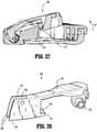
- Surgical instrument 10includes the actuation sled 536 ( FIG. 31 ) and drive assembly 560 ( FIG. 32 ).
- actuation sled 536includes a projection 535 depending from a lower surface thereof.
- FIG. 20also illustrates actuation sled 536 having projection 535 depending from a lower surface thereof.
- Projection 535is configured to travel within a slot 515 of a carrier 516. As actuation sled 536 is translated distally, projection 535 helps ensure that actuation sled 536 follows the curvature of the jaw members.
- drive assembly 560includes a lower portion 562 that is configured to travel within slot 515 of carrier 516. Additionally, an upper portion 563 of drive assembly 560 is configured to travel with a slot 513 (see also FIG. 31 , for example) in anvil plate 512. For example, the drive beam 604 extends into the slot 515 and may also extend into slot 513.
- the interaction between lower portion 562 and upper portion 563 of drive assembly 560 with slots 515 and 513, respectivelyhelps ensure that drive assembly 560 follows the curvature of the jaw members.
- drive assembly 560only engages a single slot 513 or 515.
- these structurescan be incorporated in a surgical instrument that does not have a loading unit incorporating the jaws of the instrument in a replaceable assembly and in which the staple cartridge is removable and/or reloadable.
- Carrier 816is configured to receive and support longitudinally curved cartridge 518 (see FIG. 10 ), as discussed above.
- cartridge 518can be attached to carrier 816 by adhesives, a snap-fit connection, or other type of connection.
- the radius of curvature of carrier 816is between about 1.00 inch and about 2.00 inches, and in particular, may be approximately 1.40 inches.
- carriers having other dimensionsare envisioned, e.g., the radius of curvature may be greater than 2 inches or less than 1 inch.
- Cartridge 518includes a pair of support struts 524 which rest on sidewalls 817 of carrier 816 to stabilize cartridge 518 on carrier 816.
- a proximal portion of carrier 816includes an angled cam surface 816a which is positioned for engagement with lower beam 606c ( FIG. 14 ) of clamping member 606 to facilitate pivoting of cartridge assembly 508 (including carrier 816) from the open position to the closed position.
- Carrier 816also includes a slot 815 which is configured to allow projection 535 of actuation sled 536 to travel therethrough.
- Carrier 816includes a first or outer sidewall 818 and a second or inner sidewall 819.
- a plurality of notches 820 and a plurality of reliefs 821are defined in outer and inner sidewalls 818 and 819.
- each first sidewall 818 and second sidewall 819includes two notches 820. It is envisioned that each first sidewall 818 and second sidewall 819 includes more or fewer notches 820.
- notches 820are rectangular with rounded ends and extend completely through the respective sidewalls 818, 819. It is also envisioned that notches 820 can be differently sized, shaped, and/or positioned, and that at least one or all of notches 820 can extend partially through its respective sidewall 818, 819.
- Notches 820are configured to accommodate protrusions or snap features formed on cartridge 518 to facilitate a snap-fit engagement between cartridge 518 and carrier 816.
- first sidewall 818includes five reliefs 821
- second sidewall 819includes three reliefs 821.
- each of first sidewall 818 and second sidewall 819may include more or fewer reliefs 821.
- reliefs 821are generally rectangular sections removed from sidewalls 818, 819, and extend the entire height of sidewalls 818, 819.
- reliefs 821may assume a variety of configurations and need not be rectangular.
- the inclusions of reliefs 821facilitate the extrusion, drawing and/or bending of carrier 816 during manufacturing. For example, during a bending process, reliefs 821 allow for carrier 816 to compensate for the difference in the radius of curvature between outer sidewalls 818 and inner sidewalls 819.
- the present disclosurealso relates to a method of manufacturing carrier 816.
- the methodincludes combinations of cutting, bending, extruding and drawing sheet metal into the shape of carrier 816.
- the inclusion of reliefs 821facilitates the manufacturing process by allowing the sheet metal to be bent into the desired shape.
- the process or method of manufacturing carrier 816involves fewer machining operations than manufacturing a different carrier, e.g., due to notches 820 and/or reliefs 821.
- manufacturing carrier 816which includes notches 820 for accommodating a snap-fit relationship with cartridge 518, is more efficient than manufacturing a carrier with an inner groove for accommodating a snap-fit relationship with cartridge 518.
- notches 820can be created by the same machining operation (e.g., cutting) that is already being used to cut the desired shape out of the sheet metal, for example, as opposed to having to both cut and emplace a groove in the material, which may be otherwise required.
- the design of carrier 816does not require an increase sheet gauge of metal to be used; a standard gauge is usable to provide the necessary strength of carrier 816.
- these manufacturing advantageshelp to minimize waste, time, and cost of manufacturing a carrier for use in surgical stapling instrument 10 and/or loading unit 500.
- the method of manufacturing carrier 816consists of only cutting sheet metal into a first shape, and bending the sheet metal into a final shape. Other steps such as notching a groove in carrier 816 are not necessary because notches 820, which enable engagement between carrier 816 and cartridge 518, are created by the cutting operation. Grooves were previously required to enable engagement between a carrier and a cartridge, and required being separated notched.
- the cuttingincludes cutting at least one notch 820 (e.g., two notches 820) through a first curved side of the first shape, and cutting at least one notch 820 (e.g., two notches 820) through a second curved side of the first shape.
- the cuttingmay further include cutting at least one relief 821 (e.g., three reliefs 821) through the first curved side of the first shape, and cutting at least one relief 821 (e.g., three reliefs 821) through the second curved side of the first shape.
- any number of notches 820 and reliefs 821can be provided to facilitate bending of carrier 816. It is disclosed that bending the sheet metal into a final shape includes bending the first curved side to form first sidewall 818, and bending the second curved side to create second sidewall 819.
- cartridge assembly 508is shown in accordance with embodiments of the present disclosure.
- a cartridge assembly 508 including a cartridge 518is illustrated having a plurality of slots 528 (e.g., staple retention slots) extending through corresponding openings in a tissue contacting surface 540 of cartridge 518.
- cartridge 518includes longitudinal channel 526 that is configured to allow dynamic clamping member 606 ( FIG. 11 ) and a portion of drive assembly 560 ( FIG. 32 ) to advance therethrough.
- each of an inner portion 518a (e.g., specimen side, shorter side) and an outer portion 518b (e.g., longer side) of cartridge 518includes three rows of slots 528. That is, inner portion 518a of cartridge 518 includes an inner row 528ai of slots 528, a middle row 528am of slots 528 and an outer row 528ao of slots 528, and outer portion 508b of cartridge 518 includes an inner row 528bi of slots 528, a middle row 528bm of slots 528, and an outer row 528bo of slots 528. As shown, inner rows 528ai and 528bi of slots 528 are closer to longitudinal channel 526, and outer rows 528ao and 528bo of slots 528 are farther away from longitudinal channel 526.
- FIGS. 35-37schematically illustrate different positions of staples 530 within slots 528.
- the various slots 528 lacking a staple 530 thereinare omitted in FIGS. 35-37 ; only slots 528 including a staple 530 therein are shown in FIGS. 35-37 .
- each slot 528 of rows 528bi, 528bm, and 528bo of outer portion 508b of cartridge 518is shown with a staple 530 therein, and slots 528 of inner row 528ai are shown with a staple 530 therein; slots 528 of middle row 528am and outer row 528ao lack staples 530.
- each slot 528 of rows 528bi, 528bm, and 528bois shown with a staple 530 therein, and slots 528 of middle row 528am are shown with a staple 530 therein; slots 528 of inner row 528ai and outer row 528ao lack staples 530.
- each slot 528 of rows 528bi, 528bm, and 528bois shown with a staple 530 therein
- slots 528 of inner row 528aiare shown with a staple 530 therein
- alternating slots 528 of middle row 528amare shown with a staple 530 therein
- slots 528 of outer row 528aolack staples 530
- alternating slots 528 of middle row 528amlack staples 530.
- each of the slots 528 on outer portion 518b of cartridge 518includes a staple 530 therein
- some slots 528 on inner portion 508a of cartridge 518include a staple 530 therein
- some slots 528 on inner portion 508a of cartridge 518lack a staple 530 therein.
- one portion (e.g., inner portion 508a) of cartridge 518includes fewer than three complete rows of slots 528 including staples 530.
- slots 528 of each row 528bi, 528bm, and 528boinclude a staple 530 therein, and slots 528 of outer row 528ao include a staple 530 therein, while slots 528 of inner row 528ai and middle row 528am lack staples 530.
- the disclosed staple configurationsfacilitate pathological detection of clean margins after resection of diseased tissue. That is, such configurations help physicians view and/or sample tissue directly adjacent the cut line (i.e., along longitudinal channel 526) without interference from three rows of staples 530, for example.
- tissue directly adjacent the cut linei.e., along longitudinal channel 526)
- the pathological detection and/or testing of the tissuecan include detection and/or testing for cancerous cells.
- FIGS. 34-37illustrate a curved cartridge assembly 508, it is envisioned that cartridge assembly 508 is linear (i.e., aligned with longitudinal axis "A-A" in FIG. 4 ).
- the present disclosurealso includes embodiments of cartridge assembly 508 having fewer than three complete rows of slots 528 on at least one side of longitudinal channel 526.
- each slot 528includes a staple 530 therein.
- a cartridge assembly 508 of the present disclosureincludes three complete rows of slots 528 on a first side of longitudinal channel 526, and includes two rows of slots 528 on a second side of longitudinal channel 526.
- the present disclosurecontemplates any combination of complete rows of slots 528 and partial rows of slots 528, with any or all of the slots 528 including a staple 530 therein.
- the present disclosureincludes a cartridge assembly 508 and/or a cartridge 518 having slots 528 including a plurality of staples 530 therein, and where several slots 528 (e.g., on inner side 508a of cartridge 518) are devoid of staples 530.
- the present disclosureincludes a loading unit 500 ( FIG. 3 ) including cartridge assembly 508 and cartridge 518 including various configurations of slots 528 and staples 530, as described above, and a surgical instrument 10 including cartridge assembly 508 and cartridge 518 including various configurations of slots 528 and staples 530, as described above.
- the present disclosureincludes methods of using surgical instrument 10, loading unit 500 ( FIG. 3 ), cartridge assembly 508 and/or cartridge 518 including ejecting various configurations of staples 530, as described above. Additionally, the present disclosure relates to methods of performing a surgical procedure including ejecting various configurations of staples 530, as described above.
- the staple cartridgemay have a flat tissue contacting surface, rather than a stepped surface.
- all the staplescan be the same size, or the surgical instrument can deploy two part fasteners.
- Embodiments disclosed hereincan have different sized staples arranged in a variety of configurations.
- the anvilmay have a stepped surface, or may include different surfaces, and the staple cartridge can be stepped or flat. Therefore, the above description should not be construed as limiting, but merely as exemplifications of various embodiments. Those skilled in the art will envision other modifications within the scope and spirit of the claims appended hereto.
Landscapes
- Health & Medical Sciences (AREA)
- Life Sciences & Earth Sciences (AREA)
- Surgery (AREA)
- Heart & Thoracic Surgery (AREA)
- Engineering & Computer Science (AREA)
- Biomedical Technology (AREA)
- Nuclear Medicine, Radiotherapy & Molecular Imaging (AREA)
- Medical Informatics (AREA)
- Molecular Biology (AREA)
- Animal Behavior & Ethology (AREA)
- General Health & Medical Sciences (AREA)
- Public Health (AREA)
- Veterinary Medicine (AREA)
- Surgical Instruments (AREA)
Abstract
Description
- The present disclosure relates generally to instruments for surgically joining tissue and, more specifically, to surgical instruments and loading units for use therewith, and to related methods of use.
- Various types of surgical instruments used to surgically join tissue are known in the art, and are commonly used, for example, for closure of tissue or organs in transection, resection, anastomoses, for occlusion of organs in thoracic and abdominal procedures, and for electrosurgically fusing or sealing tissue.
- One example of such a surgical instrument is a surgical stapling instrument, which may include an anvil assembly, a cartridge assembly for supporting an array of surgical staples, an approximation mechanism for approximating the cartridge and anvil assemblies, and a firing mechanism for ejecting the surgical staples from the cartridge assembly.
- During use of a surgical stapling instrument, it is common for a surgeon to approximate the anvil and cartridge members to clamp tissue and subsequently fire the instrument to emplace rows of staples in the tissue. Additionally, the surgeon may use the same instrument or a separate instrument to cut the tissue adjacent or between the row(s) of staples.
- The present disclosure relates a cartridge assembly for use with a surgical instrument. The cartridge assembly includes a cartridge, a longitudinal channel, a first row of slots, and a second row of slots. The cartridge has a proximal portion and a distal portion. The longitudinal channel extends between the proximal portion and the distal portion. The first row of slots is disposed on a first side of the longitudinal channel. At least one slot in the first row of slots is empty. The second row of slots is disposed on a second side of the longitudinal channel. At least one slot in the second row of slots has a staple disposed therein.
- In disclosed embodiments, each slot in the second row of slots includes a staple disposed therein. It is further disclosed that at least one slot in the first row of slots includes a staple disposed therein. It is also disclosed that each of the slots in the first row of slots is empty.
- Disclosed embodiments of the cartridge assembly also include three rows of slots on the first side and/or the second side of the longitudinal channel. In embodiments, each row of slots of the three rows of slots on the second side of the longitudinal channel includes at least one slot having a staple disposed therein. It is disclosed that each row of slot of the three rows of slots on the first side of the longitudinal channel includes at least one slot being empty.
- It is further disclosed that the cartridge defines a radius of curvature of between about 1 inch and about 2 inches, and that the first side of the longitudinal channel is shorter than the second side of the longitudinal channel.
- The present disclosure also relates to a surgical instrument comprising a handle assembly, an elongated portion extending distally from the handle assembly and defining a longitudinal axis, a loading unit, and a plurality of staples. The loading unit is disposed adjacent a distal end of the elongated portion, and includes an anvil assembly and a cartridge assembly. The cartridge assembly includes a cartridge having a plurality of slots arranged in rows. Some slots of the plurality of slots include one staple of the plurality of staples disposed at least partially therein, and some slots of the plurality of slots are devoid of staples.
- In disclosed embodiments, the cartridge includes a longitudinal channel extending therethrough. The plurality of slots is disposed in three rows on a first side of the longitudinal channel and in three rows on a second side of the longitudinal channel. It is disclosed that all of the slots that are devoid of staples are arranged on the first side of the longitudinal channel. It is also disclosed that the three rows of slots on the first side of the longitudinal channel include an inner row, a middle row, and an outer row. The inner row is closest to the longitudinal channel, and the outer row is farthest from the longitudinal channel. It is further disclosed that all of the slots that are devoid of staples are disposed in the middle row and the outer row on the first side of the longitudinal channel. Additionally, it is disclosed that all of the slots that are devoid of staples are disposed in the inner row and the outer row on the first side of the longitudinal channel.
- In disclosed embodiments, at least one of the inner row, the middle row or the outer row includes slots that include one staple disposed therein and includes slots that are devoid of staples.
- It is further disclosed that the cartridge is curved with respect to the longitudinal axis, and the first side of the longitudinal channel is shorter than the second side of the longitudinal slot.
- The present disclosure also relates to a method of performing a surgical procedure comprising emplacing a first set of staples from a first side of a longitudinal channel of a surgical instrument in at least one row through tissue, emplacing a second set of staples from a second side of the longitudinal channel of the surgical instrument in at least one row through tissue, wherein the first set of staples includes more staples than the second set of staples, and advancing a knife through the longitudinal channel to cut tissue.
- In disclosed embodiments, emplacing the second set of staples includes emplacing the second set of staples in a single curved row through tissue.
- In certain embodiments, the second set of staples are spaced a greater distance than the first set of staples. The second set of staples can include fewer rows of staples than the first set of staples. As such, the tissue remnant having the second set of staples has more tissue unimpeded by staples and can be better disposed for testing and/or inspection.
- In certain embodiments, pathological detection and/or testing of a tissue remnant stapled by the second set of staples is performed.
- The pathological detection and/or testing can include testing for cancer cells.
- Various embodiments of the presently disclosed surgical instrument are disclosed herein with reference to the drawings, wherein:
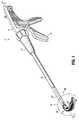
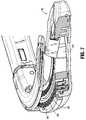
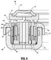
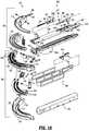
FIG. 1 is a perspective view of a surgical stapling instrument including a loading unit in accordance with the present disclosure;FIG. 1A is a perspective view of another type of surgical stapling instrument including the loading unit ofFIG. 1 in accordance with an embodiment of the present disclosure;FIG. 2 is a perspective view of a handle assembly of the surgical stapling instrument ofFIG. 1A ;FIG. 3 is a perspective view of the loading unit ofFIGS. 1 and1A ;FIG. 4 is an enlarged view of the area of detail ofFIGS. 1 and1A ;FIG. 5 is a top view of the loading unit ofFIGS. 3 and4 ;FIG. 6 is a side view of the loading unit ofFIGS. 3-5 , illustrated with a cartridge assembly in the open position;FIG. 7 is a perspective, partial cross-sectional view of the loading unit ofFIGS. 3-6 ;FIG. 8 is a transverse cross-sectional view of the loading unit ofFIGS. 3-7 ;FIG. 9 is a longitudinal cross-sectional view of a portion of the loading unit ofFIGS. 3-8 ;FIG. 10 is a perspective assembly view of the loading unit ofFIGS. 3-9 ;FIG. 11 is a perspective view of a drive assembly and dynamic clamping member of the loading unit ofFIGS. 3-10 ;FIG. 12 is an enlarged view of the area of detail ofFIG. 11 ;FIG. 13 is a perspective assembly view of the drive assembly and dynamic clamping member ofFIGS. 11 and 12 ;FIGS. 14-17 are various views of the dynamic clamping member according to an embodiment of the present disclosure;FIG. 17A is a rear view of another embodiment of a dynamic clamping member according to another embodiment of the present disclosure;FIG. 17B is a perspective view of another embodiment of a dynamic clamping member according to another embodiment of the present disclosure;FIGS. 18-20 are various views of an actuation sled in accordance with an embodiment of the present disclosure;FIGS. 21 and 22 are perspective views of staples and staple pushers in accordance with embodiments of the present disclosure;FIGS. 23-25 are perspective views of various staple pushers in accordance with embodiments of the present disclosure;FIG. 26 is a perspective view of a tissue stop for use with the loading unit ofFIGS. 3-10 ;FIG. 27 is a cross-sectional view of the tissue stop ofFIG. 26 coupled to the loading unit;FIGS. 28-30 are perspective views of the loading unit ofFIGS. 3-10 interacting with a layer of tissue at various stages of operation of the loading unit;FIG. 31 is a transverse cross-sectional view of the surgical instrument taken across a portion of the actuation sled in accordance with an embodiment of the present disclosure;FIG. 32 is a transverse cross-sectional view of the surgical instrument ofFIG. 30 taken across a portion of the drive assembly;FIG. 33 is a perspective view of a carrier of a loading unit in accordance with an embodiment of the present disclosure;FIG. 34 is a perspective view of a cartridge assembly in accordance with embodiments of the present disclosure; andFIGS. 35-37 are cut-away views of the cartridge assembly ofFIG. 34 schematically showing various positions of staples within slots of the cartridge assembly.- Embodiments of the presently disclosed surgical instrument, and loading unit for use therewith, are described in detail with reference to the drawings, wherein like reference numerals designate corresponding elements in each of the several views. As is common in the art, the term 'proximal" refers to that part or component closer to the user or operator, e.g., surgeon or physician, while the term "distal" refers to that part or component farther away from the user.
- A first type of surgical stapling instrument of the present disclosure is indicated as
reference numeral 10 inFIG. 1 . Another type of surgical stapling instrument of the present disclosure is indicated asreference numeral 10a inFIGS. 1A and2 . Additionally, while not explicitly shown, the present application also relates to surgical stapling instruments having parallel jaw members and to electrosurgical instruments used to join tissue. Collectively, all surgical instruments (includingsurgical stapling instruments reference numeral 10. Similarly, several features that are common to both surgical stapling instruments are collectively referred to as the same reference number (e.g., handleassembly 12,rotation knob 14, and endoscopic portion 18). Further details of an endoscopic surgical stapling instrument are described in detail in commonly-ownedU.S. Patent No. 6,953,139 to Milliman et al. , the entire contents of which are hereby incorporated by reference herein. - A loading unit 500 (e.g., a disposable loading unit or a reusable loading unit) for use with
surgical instrument 10 is shown inFIGS. 3-10 and28-30 .Loading unit 500 is attachable to an elongated orendoscopic portion 18 ofsurgical instrument 10, e.g., to allowsurgical instrument 10 to have greater versatility.Loading unit 500 may be configured for a single use, and/or may be configured to be used more than once. Examples of loading units for use with a surgical stapling instrument are disclosed in commonly-owned United States Patent No.5,752,644 to Bolanos et al. , the entire contents of which are hereby incorporated by reference herein. The loading unit shown includes a proximal body portion that is attachable to an elongated portion of a surgical instrument having a handle assembly. However, the tool assembly can be incorporated in a surgical instrument in which a staple cartridge is removable and replaceable and does not include a detachable portion of the elongated portion of the instrument. Furthermore, the tool assembly can be incorporated in a reload that is attachable to a powered surgical handle or system, or to a robotic system. Loading unit 500 includes aproximal body portion 502 and atool assembly 504.Proximal body portion 502 defines a longitudinal axis "A-A," and is releasably attachable to a distal end ofelongated body portion 18 ofsurgical instrument 10.Tool assembly 504 includes a pair of jaw members including ananvil assembly 506 and acartridge assembly 508. One jaw member is pivotal in relation to the other. In the illustrated embodiments,cartridge assembly 508 is pivotal in relation toanvil assembly 506 and is movable between an open or unclamped position (e.g.,FIGS. 4 and6 ) and a closed or approximated position (e.g.,FIG. 8 ).Cartridge assembly 508 is urged in the open position via a biasing member, e.g., a pair of compression springs 533 disposed betweenanvil cover 510 and cartridge 518 (seeFIG. 10 ).- With reference to
FIGS. 1 and10 , for example,tool assembly 504 includesanvil assembly 506 andcartridge assembly 508. As shown, each ofanvil assembly 506 andcartridge assembly 508 is longitudinally curved. That is,anvil assembly 506 andcartridge assembly 508 are curved with respect to the longitudinal axis "A-A" defined byproximal body portion 502. As used herein with respect to curved parts of thesurgical instrument 10 of the present disclosure, the term "distal," which typically refers to that part or component of the instrument that is farther away from the user, refers to the portion of the curved part that is farthest along an axis that follows the curve of the curved part. That is, while an intermediate portion of a curved part may be farther from the user during use, the portion of the curved part that is farthest along its axis is considered "distal." - In disclosed embodiments, the radius of curvature of both
anvil assembly 506 andcartridge assembly 508 is between about 1.00 inches and about 2.00 inches, and in particular, may be approximately 1.40 inches. The curved jaw members, as compared to straight jaw members, may help facilitate access to lower pelvis regions, e.g., during lower anterior resection ("LAR"). Additionally, the inclusion of curved jaw members may allow increased visualization to a surgical site and may also allow more room for a surgeon to manipulate target tissue or the jaw members themselves. - With reference to
FIG. 10 ,anvil assembly 506 includes a longitudinallycurved anvil cover 510 and a longitudinallycurved anvil plate 512, which includes a plurality of staple forming depressions 514 (FIG. 9 ). In disclosed embodiments, the radius of curvature of bothanvil cover 510 andanvil plate 512 is between about 1.00 inches and about 2.00 inches, and in particular, may be approximately 1.40 inches.Anvil plate 512 is secured to an underside of anvil cover to define a channel 511 (FIG. 8 ) betweenplate 512 andcover 510. Whentool assembly 504 is in the approximated position (FIG. 8 ),staple forming depressions 514 are positioned in juxtaposed alignment withcartridge assembly 508. Cartridge assembly 508 includes a longitudinally curved channel orcarrier 516 which receives and supports a longitudinallycurved cartridge 518. Thecartridge 518 can be attached to the channel or carrier by adhesives, a snap-fit connection, or other connection. In disclosed embodiments, the radius of curvature of bothcarrier 516 andcartridge 518 is between about 1.00 inches and about 2.00 inches, and in particular, may be approximately 1.40 inches.Cartridge 518 includes a pair of support struts 524 which rest onsidewalls 517 ofcarrier 516 to stabilizecartridge 518 oncarrier 516. Support struts 524 also set the height or location ofcartridge 518 with respect toanvil plate 512. An external surface ofcarrier 516 includes anangled cam surface 516a.Cartridge 518 defines a plurality of laterally spacedstaple retention slots 528, which are configured as holes in tissue contacting surface 540 (seeFIG. 7 ). Eachslot 528 is configured to receive a staple 530 therein.Cartridge 518 also defines a plurality of cam wedge slots 529 (seeFIG. 9 ) which accommodatestaple pushers 532 and which are open on the bottom (i.e., away from tissue contacting surface 540) to allow a longitudinallycurved actuation sled 536 to pass therethrough.Staple cartridge 518 includes a central longitudinally curved slot channel orchannel 526, and three longitudinally curved rows ofstaple retention slots 528 positioned on each side of curved longitudinal channel 526 (seeFIGS. 7 and8 ). In disclosed embodiments, the radius of curvature of bothchannel 526 andpusher 532 is between about 1.00 inches and about 2.00 inches, and in particular, may be approximately 1.40 inches. More specifically,actuation sled 536 passes throughcam wedge slots 529 and forcesstaple pushers 532 towardsrespective staples 530. The staples are then forced out of their respectivestaple retention slots 528.- With reference to
FIGS. 21 and 22 ,pushers 532 of the illustrated embodiments each engage two ormore staples 530.Pushers 532 include a single distally-locatedtriple pusher 532a (FIG. 23 ), a single proximally-locateddouble pusher 532b (FIG. 24 ), and a series oftriple pushers 532c (onetriple pusher 532c is shown inFIG. 25 ) which extend betweendouble pusher 532b andtriple pusher 532a on each side ofchannel 526. In disclosed embodiments, portions ofpushers pusher - During operation of
stapler 10, actuation of itsmovable handle 22 through successive strokes causes distal advancement of its drive bar 30 (a distal portion of which is illustrated inFIG. 2 ), such thatdrive bar 30 pushes adrive assembly 560 throughcartridge 518. (Further details of how actuation ofmovable handle 22 causes distal advancement ofdrive bar 30 are explained inU.S. Patent No. 6,953,139 to Milliman et al. , which has been incorporated by reference herein.) The movement ofdrive assembly 560, and in particular, adynamic clamping member 606 affixed thereto, moves a longitudinally curved actuation sled 536 (seeFIGS. 18-20 ) throughcartridge 518. Assled 536 moves throughcartridge 518, longitudinally curved cam wedges 534 ofactuation sled 536 sequentially engagepushers 532 to movepushers 532 vertically withinstaple retention slots 528 and ejectstaples 530 intostaple forming depressions 514 ofanvil plate 512. Subsequent to the ejection ofstaples 530 from retention slots 528 (and into tissue), acutting edge 606d ofdynamic clamping member 606 severs the stapled tissue as cuttingedge 606d travels throughcurved slot 526 ofcartridge 518. - Referring to
FIG. 8 and in accordance with embodiments of the present disclosure,cartridge 518 includes atissue contacting surface 540 includingsurfaces Surface 540a is adjacentlongitudinal slot 526 and defines a first gap betweentissue contacting surface 540 and abottom surface 544 ofanvil plate 512.Surface 540b is locatedadjacent surface 540a and defines a second gap betweentissue contacting surface 540 andbottom surface 544.Surface 540c is located proximal to an outer perimeter ofcartridge 518 and defines a third gap betweentissue contacting surface 540 andbottom surface 544. The first gap is less than the second gap, which is less than the third gap. Whenanvil 506 is approximated towardscartridge 508, layers of tissue located betweenbottom surface 544 andtissue contacting surface 540 are compressed. Since the first gap is the smallest, tissue located betweensurface 540a andbottom surface 544 is compressed the most. Similarly, the tissue located betweensurface 540c andbottom surface 544 is compressed the least, with the tissue located betweensurface 540b andbottom surface 544 being compressed to an intermediate degree. The arrangement ofsurfaces tissue contacting surface 540 provides a tissue compression gradient extending transverse to a longitudinal axis of thecartridge 518. - Referring to
FIGS. 8 ,21 and 22 in conjunction with the stepped arrangement oftissue contacting surface 540, the illustrated embodiment ofstaples 530 include varying leg lengths for cooperating with the varying gaps.Staples 530a have the shortest leg length and are associated withsurface 540a. Similarly,staples 530b have an intermediate leg length and are associated withsurface 540b, whilestaples 530c have the longest leg length and are associated withsurface 540c. The leg length ofstaples 530b is between the leg length ofstaples surface 540a andbottom surface 544 has been compressed the most, the resulting thickness of the tissue is at a minimum, thereby allowing a staple having a shorter leg length (i.e. staple 530a) to be used to join the layers of tissue. The layers of tissue betweensurface 540b andbottom surface 544 are compressed to an intermediate degree of compression and the resulting thickness of the tissue layers allows a staple having an intermediate leg length (i.e. staple 530b) to be used when joining the layers of tissue. The layers of tissue betweensurface 540c andbottom surface 544 are compressed the least amount and are thicker than the other layers requiring staples that have the longest leg length (i.e.staples 530c) for joining the layers of tissue. - In particular, the illustrated embodiment of
pusher 532 includesplates staples Plate 531a has a height which is greater than the height ofplate 531b. Additionally, the height ofplate 531b is greater than the height ofplate 531c.Pusher 532 further includes cam members 542 that are longitudinally staggered. Assled 536 translates distally throughcartridge 518, cam wedges 534 engage cam members 542 ofpusher 532, thereby urgingpusher 532 in a direction transverse to the longitudinal axis ofcartridge 518 and urgingstaples 530 towardsstaple forming depressions 514 ofanvil plate 512. In particular, cam wedges 534 are longitudinally staggered such that when they engage staggered cam members 542, the resulting forces applied to movepusher 532 towardstissue contacting surface 540 are evenly applied. - With continued reference to
FIGS. 21 and 22 ,staples pusher 532c fromFIG. 25 is shown). Additionally, cam members 542 of eachpusher 532 includecam surfaces cam surface FIGS. 21-25 ,cam wedges 534a are configured tocam surfaces 542a;cam wedges 534b are configured to engagecam surfaces 542b;central section 534c ofsled 536 is configured to travel throughslot 526. - Referring to
FIG. 20 , the illustrated embodiment ofactuation sled 536 includes a longitudinallycurved projection 535 depending from a lower surface thereof.Projection 535 is configured to travel within a slot 515 (FIG. 10 ) of channel orcarrier 516. In disclosed embodiments, the radius of curvature of both cam wedges 534 andprojection 535 is between about 1.00 inches and about 2.00 inches, and in particular, may be approximately 1.40 inches. - With reference to
FIG. 10 ,proximal body portion 502 includes an inner body 503 formed from molded half-sections drive assembly 560 and adrive locking assembly 564.Proximal body portion 502 is coupled totool assembly 504 by a mountingassembly 570. Mountingassembly 570 has a pair ofextensions 576 which extend into a proximal end ofcarrier 516. Eachextension 576 has atransverse bore 578 which is aligned with ahole 580 in thecartridge 518 such that mountingassembly 570 is pivotally secured tocartridge 518 bypin 582. Mountingassembly 570 is fixedly secured to half-section 503a by a pair ofvertical protrusions 584.Vertical protrusions 584 extend upwardly from mountingassembly 570 and frictionally fit into corresponding recesses (not shown) in half-section 503a. - With continued reference to
FIG. 10 , the illustrated embodiment ofanvil cover 510 includes aproximally extending finger 588 having a pair ofcutouts 590 formed therein.Cutouts 590 are positioned on each lateral side offinger 588 to helpsecure anvil cover 510 to half-section 503a. More particularly, half-section 503a includes achannel 505 therein, andchannel 505 includes a pair of protrusions 505a.Finger 588 ofanvil cover 510 mechanically engageschannel 505 of half-section 503a, such thatcutouts 590 are aligned withprotrusions 505a. Anouter sleeve 602 covers the finger and channel. The configuration offinger 588 andchannel 505 facilitates a secure connection betweenanvil cover 510 and half-section 503a. Moreover, this connection results in a non-movable (e.g., non-pivotable)anvil assembly 506 with respect toproximal body portion 502. - Referring to
FIGS. 11-13 ,drive assembly 560 includes aflexible drive beam 604 which is constructed from three stackedmetallic sheets 604 a-c and aproximal engagement portion 608. At least a portion ofdrive beam 604 is sufficiently flexible to be advanced through the curvature of thetool assembly 504.Drive beam 604 has a distal end which is secured to adynamic clamping member 606 via abutt weld 606f (FIG. 12 ).Spot welds 606h, which are configured to holdsheets 604 a-c together, are also shown inFIG. 12 . Engagement section 608 is fastened to a proximal portion ofmiddle sheet 604b (e.g., via a butt weld) and includes a stepped portion defining a shoulder 610. A proximal end ofengagement section 608 includes diametrically opposed inwardly extendingfingers 612.Fingers 612 engage ahollow drive member 614 to fixedlysecure drive member 614 to the proximal end ofbeam 604.Drive member 614 defines aproximal porthole 616 which receives the distal end of a control rod of drive bar 30 (seeFIG. 2 ) when loadingunit 500 is attached tosurgical stapling instrument 10.- With reference to
FIGS. 14-17 ,dynamic clamping member 606 includes avertical strut 606a, anupper beam 606b and alower beam 606c. A knife or cuttingedge 606d is formed on a distal face ofvertical strut 606a. As illustrated, the width ofvertical strut 606a is equal to the width ofdrive beam 604 of drive assembly 560 (seeFIG. 12 ). With particular reference toFIG. 16 ,vertical strut 606a andknife 606d are longitudinally curved from a firstlateral side 606e of clamping member towards a secondlateral side 606f of clampingmember 606. Bothupper beam 606b andlower beam 606c are linearly disposed with respect to longitudinal axis "A-A." - As illustrated in
FIGS. 14-17A , the present disclosure includes embodiments ofdynamic clamping member 606 that are asymmetrical. For instance, in the embodiment illustrated inFIGS. 15 and 17 ,lower beam 606c is thicker thanupper beam 606b. In this embodiment,dynamic clamping member 606 is asymmetrical about horizontal axis "H-H" illustrated inFIG. 17 . It is envisioned thatlower beam 606c includes a thickness "TL", which is between about 0.050 inches and about 0.100 inches, and in particular, may be approximately 0.068 inches. It is envisioned thatupper beam 606b includes a thickness "TU", which is between about 0.025 inches and about 0.050 inches, and in particular, is approximately 0.037 inches. - An additional example of an asymmetrical
dynamic clamping member 606 is also illustrated inFIG. 17 . In this embodiment, the transverse cross-sectional shape ofupper beam 606b includes an upper planar surface 606b1 and a lower planar surface 606b2. The cross-sectional shape oflower beam 606c includes an upper planar surface 606c1 and a lower arcuate surface 606c2. In this embodiment,dynamic clamping member 606 is asymmetrical about the horizontal axis "H-H." - The embodiment shown in
FIGS. 16 and 17 illustrates proximal portion ofvertical strut 606a being off-center with respect to the remainder of clampingmember 606. More particularly, it is envisioned that the center ofvertical strut 606a is between about 0.070 inches and about 0.090 inches (e.g., approximately 0.080 inches) from firstlateral side 606e of clampingmember 606, and is between about 0.90 inches and about 0.110 inches (e.g., approximately 0.100 inches) from secondlateral side 606f of clampingmember 606. In this embodiment,dynamic clamping member 606 is asymmetrical about vertical axis "V-V" illustrated inFIG. 17 . - With reference to
FIG. 17A , dynamic clamping member 606' is shown.Lower beam 606c' is wider thanupper beam 606b' of dynamic clamping member 606'. More particularly, it is envisioned that a width "wl" oflower beam 606c' is between about 0.180 inches and about 0.200 inches, and that a width "wu" ofupper beam 606b' is between about 0.160 inches and about 0.180 inches. In this embodiment, dynamic clamping member 606' is asymmetrical about the horizontal axis "H-H." Further, while not explicitly shown, it is envisioned thatupper beam 606b' is wider thanlower beam 606c' of adynamic clamping member 606 of the present disclosure. Additionally, dynamic clamping member 606' is shown as being longitudinally linear (vis-à-vis longitudinally curved), in accordance with embodiments of the present disclosure. - The asymmetrical embodiments of
dynamic clamping member 606 of the present disclosure help ensure proper orientation ofdynamic clamping member 606 during assembly ofsurgical stapling instrument 10 orloading unit 500. That is, the asymmetry ofdynamic clamping member 606 preventsdynamic clamping member 606 from improper placement with respect totool assembly 504, sincedynamic clamping member 606 can only physically fit in a particular orientation. In particular, the asymmetry ensures thatknife 606d faces distally and is positioned to travel through the space betweencartridge assembly 508 andanvil assembly 506, for example. - With reference to
FIG. 17B , the present disclosure includes another embodiment of adynamic clamping member 606" that is also configured to help ensure proper orientation ofdynamic clamping member 606" during assembly ofsurgical stapling instrument 10 orloading unit 500. Dynamic clampingmember 606" includes aprotrusion 607 extending from aproximal surface 606i thereof. In the illustrated embodiment, adrive assembly 560" has a smaller height than embodiment of drive assembly 560' illustrated inFIGS. 10-13 .Protrusion 607 is shown being disposed on a lower portion ofdynamic clamping member 606" (i.e., on the opposite side as cuttingedge 606d") and to one side ofdrive assembly 560", but it is envisioned thatprotrusion 607 is disposed on the other side ofdrive assembly 560". - As discussed above, the inclusion of
protrusion 607 helps ensure proper orientation ofdynamic clamping member 606". More particularly, it is envisioned thatextensions 576 of mountingassembly 570 would physically prevent further assembly ofdynamic clamping member 606" being incorrectly fastened to drive assembly 560" (e.g., whendynamic clamping member 606" is up-side-down with respect to drive assembly 560". - It is further envisioned that
dynamic clamping member 606, 606' may include any combination of the asymmetrical features discussed herein and may also includeprotrusion 607 ofdynamic clamping member 606". - With additional reference to
dynamic clamping member 606 ofFIGS. 14-17A , it is envisioned that each ofupper beam beam member 606 and cartridge andanvil assemblies tool assembly 504. - Referring back to
FIG. 8 ,channel 511 is configured and dimensioned accordingly to accommodate a corresponding embodiment ofupper beam 606b of clampingmember 606;slot 526 is configured and dimensioned accordingly to accommodate a corresponding embodiment ofvertical strut 606a of clampingmember 606. As can be appreciated, when used with the embodiment ofdynamic clamping member 606 ofFIG. 17A ,channel 511 is too narrow to accommodatelower beam 606c ofdynamic clamping member 606. - With reference to
FIG. 10 , whendrive assembly 560 is advanced distally withintool assembly 504,upper beam 606b moves withinchannel 511 defined betweenanvil plate 512 andanvil cover 510, andlower beam 606c moves over an exterior surface ofcarrier 516. Whenlower beam 606c engages and moves overcam surface 516a,cartridge assembly 508 pivots from the open position to the closed position. Asdynamic clamping member 606 continues to move distally along and throughtool assembly 504, the maximum gap betweenanvil plate 512 andcartridge 518 is defined by engagement oflayer 606e onupper beam 606b (FIG. 12 ) and a lowersurface defining channel 511, and engagement of alayer 606g onlower beam 606c with the external surface ofcarrier 516. In disclosed embodiments, the height ofchannel 511 is greater than the height ofupper beam 606b, providing clearance between the upper surface ofdynamic clamping member 606 and theanvil plate 512 so thatupper beam 606b of dynamic clamping member 600 does not simultaneously engage the upper and lower surfaces ofanvil channel 511. - With continued reference to
FIG. 10 ,loading unit 500 includes alocking mechanism 564 including a lockingmember 620 and a lockingmember actuator 622. Lockingmember 620 is rotatably supported within a longitudinal oraxial slot 625 formed in a proximal portion of anupper housing half 503a of inner body 503 ofloading unit 500. Lockingmember 620 is movable from a first position, in which lockingmember 620 maintainsdrive assembly 560 in a prefired position, to a second position in which driveassembly 560 is free to move axially. - Locking
member 620 includes asemi-cylindrical body 624 which is slidably positioned withintransverse slot 625 formed inupper housing half 503a of body portion 503.Body 624 includes a radially inwardly extendingcam member 628 and a radially inwardly extendingfinger 630.Finger 630 is dimensioned to be received within anotch 632 formed indrive assembly 560. Engagement offinger 630 innotch 632 ofdrive assembly 560 prevents drive assembly 560 from moving linearly within body portion 503 to prevent actuation ofloading unit 500 prior to attachment ofloading unit 500 tosurgical instrument 10. - Locking
member actuator 622 is slidably positioned withinaxial slot 625 formed in upperhousing half section 503a of body portion 503 ofloading unit 500.Actuator 622 includes aproximal abutment member 636, adistal spring guide 627, and acentral cam slot 640.Axial slot 641 in thehousing half section 503a intersectstransverse slot 625 such thatcam member 628 of lockingmember 620 is slidably positioned withincam slot 640 of lockingmember actuator 622. A biasing member orspring 642 is positioned aboutspring guide 627 between a distal surface ofactuator 622 and awall 641 a defining the distal end ofaxial slot 641.Spring 642 urges actuator 622 to a first position withinaxial slot 641. In the first position,abutment member 636 is positioned oninsertion tip 650 of proximal body portion 502 (FIG. 3 ) andcam slot 640 is positioned to locatecam member 628 such thatfinger 630 oflock member 620 is positioned withinnotch 632 ofdrive assembly 560. - Prior to attachment of
loading unit 500 ontosurgical instrument 10,spring 642 urges actuator 622 to the first position to maintain thelock member 620 in its first position as discussed above. Wheninsertion tip 650 ofloading unit 500 is linearly inserted into the open end of the body portion 18 (FIG. 2 ) ofsurgical instrument 10,nubs 652 of insertion tip 650 (FIG. 3 ) move linearly through slots (not shown) formed in open end ofbody portion 18. Asnubs 652 pass through the slots, the proximal end ofabutment member 636, which is angularly offset fromnubs 652, abuts a wall defining the slots for receiving nubs. Asloading unit 500 is moved farther into body portion, lockingmember actuator 622 is moved from its first position to its second position. Asactuator 622 is moved to its second position,lock member 620 is cammed from its first position engaged withnotch 632 ofdrive assembly 560 to its second position to movefinger 630 fromnotch 632. The locking mechanism including lockingmember 620 and lockingmember actuator 622 prevents advancement of thedrive assembly 560 ofloading unit 500 prior to loading ofloading unit 500 onto asurgical instrument 10. - In the embodiments illustrated in
FIGS. 3 and10 , lockingmember actuator 622 includes anarticulation lock portion 637 disposed thereon. In particular,articulation lock portion 637 extends in an approximate right angle fromabutment member 636.Articulation lock portion 637 is configured to physically prevent the longitudinal translation of an articulation member (not shown) of a handle portion of a surgical instrument having articulation capabilities. That is, even when loadingunit 500 is engaged with asurgical instrument 10 that is otherwise capable of articulation (i.e., pivotable movement of the jaw members with respect to the elongated portion 18),articulation lock portion 637 ofloading unit 500 prevents an articulation member from enteringloading unit 500. - Referring to
FIG. 10 , upper half-section 503a ofproximal body portion 502 defines alongitudinal slot 660 which receives aleaf spring 662.Leaf spring 662 is confined withinslot 660 byouter sleeve 602.Leaf spring 662 has an angledproximal end 664 which is positioned to abut shoulder 610 (FIG. 11 ) ofengagement section 608 ofdrive beam 604 whendrive beam 604 is in its retracted position. Whendrive beam 604 is advanced distally by advancingdrive bar 30, as described above,leaf spring 662 is flexed upwardly by shoulder 610 ofdrive beam 604 to permit distal movement ofdrive beam 604. - Referring to
FIGS. 4 ,7 , and26-30 ,loading unit 500 also includes atissue stop 700.Tissue stop 700 includes abody 710, a pair oflegs 720 extending proximally from thebody 710, a stoppingportion 730, a pair of laterally opposedprotrusions 740 extending transversely from body 710 (SeeFIG. 26 ), and aknife channel 750 disposed between pair oflegs 720.Tissue stop 700 is pivotally connected to a distal portion ofcartridge assembly 508 via the engagement betweenprotrusions 740 and a corresponding pair of apertures (not shown) disposed withincartridge assembly 508.Cartridge assembly 508 includes an opening 519 (FIGS. 7 and10 ) adapted to receive bothlegs 720 oftissue stop 700. Arecess 521 is positioned distally ofopening 519 and is adapted to receive a portion oftissue stop 700 therein. Therecess 521 andopening 519 are shown inFIG. 10 . Tissue stop 700 is movable between a first position (FIG. 4 ), which corresponds to when the jaw members are in an open position where anupper surface 701 thereof is disposed betweencartridge assembly 508 and anvil assembly 506 (FIG. 4 illustrates the jaw members in a partially approximated position;FIG. 6 illustrates the jaw members in a fully opened position), and a second position (FIG. 30 ), which corresponds to when the jaw members are in the approximated position and whereupper surface 701 oftissue stop 700 is substantially flush withtissue contacting surface 514 ofcartridge 518. (InFIG. 30 ,upper surface 701 is hidden asupper surface 701 is withincartridge assembly 508.) A biasing member 760 (FIG. 10 ), a portion of which is disposed aroundprotrusion 740, urges tissue stop 700 towards its first position.Tissue stop 700 also includes a finger 770 (FIG. 26 ) extending distally from eachleg 720. With specific reference toFIG. 27 , when the jaw members are in the open position,fingers 770 oftissue stop 700 engage alip 523 disposed oncartridge assembly 508 to limit the amount of movement imparted by biasingmember 760 in the general direction of arrow "B" inFIG. 27 .- When tissue stop 700 is in its first position, tissue "T" is proximally insertable (in the general direction of arrow "A" in
FIG. 28 ) from distally beyondtissue stop 700, to a location that is between anvil assembly 206 andcartridge assembly 508 and proximal of tissue stop 700 (seeFIGS. 28 and 29 ). In this position, stoppingportion 730, which is disposed at an oblique angle (e.g., between about 45° and about 90°) with respect to tissue contacting 540 ofcartridge assembly 508, impedes tissue from distally escaping thetool assembly 504. When the jaw members are approximated (e.g., whencartridge assembly 508 is pivoted towards anvil assembly 506), tissue stop 700 (or tissue "T")contacts anvil assembly 506, thus causing tissue stop 700 to pivot from its first position towards its second position.Legs 720 oftissue stop 700 are configured to lie within opening 519 (i.e., equal to or below the tissue contacting surface 540) ofcartridge assembly 508 whentissue stop 700 is in its second position, such thatlegs 720 do not interfere with the location of the tissue with respect to thecartridge assembly 508 and respect to anvil assembly 506 (i.e., so that the staples can be deployed into tissue lying over the tissue stop). When thecartridge assembly 508 moves away fromanvil assembly 506,tissue stop 700, under the influence of biasingmember 760, returns to its first position. - With additional regard to
knife channel 750,knife channel 750 is configured to allowvertical strut 606a (includingcutting edge 606d) ofdynamic clamping member 606 to travel distally past a portion of tissue stop 700 (i.e., at least to a location adjacent the distal-most longitudinal slot 528). Additionally, it is envisioned that at least a portion of knife channel 750 (e.g., the portion that is contacted by cuttingedge 606d) is over molded with plastic or another suitable material. - While not explicitly illustrated, it is also envisioned that
tissue stop 700 is usable with a surgical instrument having parallel jaws and/or an electrosurgical instrument. An example of a surgical instrument having parallel jaws is described in commonly-ownedU.S. Pat. No. 7,237,708 to Guy et al. , the entire contents of which are hereby incorporated by reference herein. An example of an electrosurgical instrument is described in commonly-owned Patent Application No.10/369,894, filed on February 20, 2003 - The present disclosure also relates methods of using the described
surgical instrument 10 orloading unit 500 to perform a lower anterior resection. Such a method includes providingsurgical instrument 10 orloading unit 500, positioning jaw members adjacent tissue, approximating one jaw member (e.g., cartridge assembly 508) with respect to the other jaw member (e.g., anvil assembly 506), advancingdrive assembly 560 such thatdynamic clamping member 606 and at least a portion ofdrive assembly 560 move along a curvilinear path to causestaples 530 to be ejected into tissue "T" and to cut tissue "T." In certain embodiments, the jaw members are approximated, and the interior of the intestinal tissue is then washed out or otherwise cleansed. The tissue is then cut and stapled. In this way, the interior intestinal tissue is cleansed up to the location of the jaw members. - The present disclosure also relates to methods of assembling
surgical instrument 10 orloading unit 500. Such a method includes positioning asymmetricaldynamic clamping member 606, 606' in mechanical engagement with a portion oftool assembly 504, and wherein the positioning step automatically results in the proper positioning of asymmetricaldynamic clamping member 606. Another method includes attachingdynamic clamping member 606" to drive assembly 560" in a way that would enable fail-safe positioning ofdynamic clamping member 606" with respect totool assembly 504. - Other features of the present disclosure are shown in the cross-sectional views of
FIGS. 31 - 32 .Surgical instrument 10 includes the actuation sled 536 (FIG. 31 ) and drive assembly 560 (FIG. 32 ). - With particular reference to
FIG. 31 , a transverse cross-sectional view of surgical instrument 10 (e.g., loading unit) taken along a portion ofactuation sled 536 is shown. The jaw members ofsurgical instrument 10 are shown and include ananvil assembly 506 and acartridge assembly 508, which includes a channel orcarrier 516. Here,actuation sled 536 includes aprojection 535 depending from a lower surface thereof. (FIG. 20 also illustratesactuation sled 536 havingprojection 535 depending from a lower surface thereof.)Projection 535 is configured to travel within aslot 515 of acarrier 516. Asactuation sled 536 is translated distally,projection 535 helps ensure thatactuation sled 536 follows the curvature of the jaw members. - With particular reference to
FIG. 32 , a transverse cross-sectional view ofsurgical instrument 10 taken along a portion ofdrive assembly 560 is shown. Here,drive assembly 560 includes alower portion 562 that is configured to travel withinslot 515 ofcarrier 516. Additionally, an upper portion 563 ofdrive assembly 560 is configured to travel with a slot 513 (see alsoFIG. 31 , for example) inanvil plate 512. For example, thedrive beam 604 extends into theslot 515 and may also extend intoslot 513. Upon distal translation ofdrive assembly 560, the interaction betweenlower portion 562 and upper portion 563 ofdrive assembly 560 withslots drive assembly 560 follows the curvature of the jaw members. It is also envisioned and within the scope of the present disclosure that drive assembly 560 only engages asingle slot - With reference to
FIG. 33 , an alternate embodiment of curved channel orcarrier 816 is shown.Carrier 816 is configured to receive and support longitudinally curved cartridge 518 (seeFIG. 10 ), as discussed above. For example,cartridge 518 can be attached tocarrier 816 by adhesives, a snap-fit connection, or other type of connection. In disclosed embodiments, the radius of curvature ofcarrier 816 is between about 1.00 inch and about 2.00 inches, and in particular, may be approximately 1.40 inches. Alternatively, carriers having other dimensions are envisioned, e.g., the radius of curvature may be greater than 2 inches or less than 1 inch.Cartridge 518 includes a pair of support struts 524 which rest onsidewalls 817 ofcarrier 816 to stabilizecartridge 518 oncarrier 816. A proximal portion ofcarrier 816 includes anangled cam surface 816a which is positioned for engagement withlower beam 606c (FIG. 14 ) of clampingmember 606 to facilitate pivoting of cartridge assembly 508 (including carrier 816) from the open position to the closed position.Carrier 816 also includes aslot 815 which is configured to allowprojection 535 ofactuation sled 536 to travel therethrough. Carrier 816 includes a first orouter sidewall 818 and a second orinner sidewall 819. A plurality ofnotches 820 and a plurality ofreliefs 821 are defined in outer andinner sidewalls first sidewall 818 andsecond sidewall 819 includes twonotches 820. It is envisioned that eachfirst sidewall 818 andsecond sidewall 819 includes more orfewer notches 820. As illustrated,notches 820 are rectangular with rounded ends and extend completely through therespective sidewalls notches 820 can be differently sized, shaped, and/or positioned, and that at least one or all ofnotches 820 can extend partially through itsrespective sidewall Notches 820 are configured to accommodate protrusions or snap features formed oncartridge 518 to facilitate a snap-fit engagement betweencartridge 518 andcarrier 816.- In the illustrated embodiment of
carrier 816,first sidewall 818 includes fivereliefs 821, andsecond sidewall 819 includes threereliefs 821. As can be appreciated, each offirst sidewall 818 andsecond sidewall 819 may include more orfewer reliefs 821. In the illustrated embodiment,reliefs 821 are generally rectangular sections removed fromsidewalls sidewalls reliefs 821 may assume a variety of configurations and need not be rectangular. The inclusions ofreliefs 821 facilitate the extrusion, drawing and/or bending ofcarrier 816 during manufacturing. For example, during a bending process,reliefs 821 allow forcarrier 816 to compensate for the difference in the radius of curvature betweenouter sidewalls 818 andinner sidewalls 819. - The present disclosure also relates to a method of
manufacturing carrier 816. The method includes combinations of cutting, bending, extruding and drawing sheet metal into the shape ofcarrier 816. As can be appreciated, the inclusion ofreliefs 821 facilitates the manufacturing process by allowing the sheet metal to be bent into the desired shape. It is envisioned that the process or method ofmanufacturing carrier 816 involves fewer machining operations than manufacturing a different carrier, e.g., due tonotches 820 and/orreliefs 821. For instance, it envisioned thatmanufacturing carrier 816, which includesnotches 820 for accommodating a snap-fit relationship withcartridge 518, is more efficient than manufacturing a carrier with an inner groove for accommodating a snap-fit relationship withcartridge 518. That is,notches 820 can be created by the same machining operation (e.g., cutting) that is already being used to cut the desired shape out of the sheet metal, for example, as opposed to having to both cut and emplace a groove in the material, which may be otherwise required. Additionally, the design ofcarrier 816 does not require an increase sheet gauge of metal to be used; a standard gauge is usable to provide the necessary strength ofcarrier 816. As can be appreciated, these manufacturing advantages help to minimize waste, time, and cost of manufacturing a carrier for use insurgical stapling instrument 10 and/orloading unit 500. - It is further envisioned that the method of
manufacturing carrier 816 consists of only cutting sheet metal into a first shape, and bending the sheet metal into a final shape. Other steps such as notching a groove incarrier 816 are not necessary becausenotches 820, which enable engagement betweencarrier 816 andcartridge 518, are created by the cutting operation. Grooves were previously required to enable engagement between a carrier and a cartridge, and required being separated notched. In this method, the cutting includes cutting at least one notch 820 (e.g., two notches 820) through a first curved side of the first shape, and cutting at least one notch 820 (e.g., two notches 820) through a second curved side of the first shape. The cutting may further include cutting at least one relief 821 (e.g., three reliefs 821) through the first curved side of the first shape, and cutting at least one relief 821 (e.g., three reliefs 821) through the second curved side of the first shape. Alternatively, any number ofnotches 820 andreliefs 821 can be provided to facilitate bending ofcarrier 816. It is disclosed that bending the sheet metal into a final shape includes bending the first curved side to formfirst sidewall 818, and bending the second curved side to createsecond sidewall 819. - Referring now to
FIGS. 34-37 ,cartridge assembly 508 is shown in accordance with embodiments of the present disclosure. With particular reference toFIG. 34 , acartridge assembly 508 including acartridge 518 is illustrated having a plurality of slots 528 (e.g., staple retention slots) extending through corresponding openings in atissue contacting surface 540 ofcartridge 518. Additionally,cartridge 518 includeslongitudinal channel 526 that is configured to allow dynamic clamping member 606 (FIG. 11 ) and a portion of drive assembly 560 (FIG. 32 ) to advance therethrough. - More specifically, each of an
inner portion 518a (e.g., specimen side, shorter side) and anouter portion 518b (e.g., longer side) ofcartridge 518 includes three rows ofslots 528. That is,inner portion 518a ofcartridge 518 includes an inner row 528ai ofslots 528, a middle row 528am ofslots 528 and an outer row 528ao ofslots 528, andouter portion 508b ofcartridge 518 includes an inner row 528bi ofslots 528, a middle row 528bm ofslots 528, and an outer row 528bo ofslots 528. As shown, inner rows 528ai and 528bi ofslots 528 are closer tolongitudinal channel 526, and outer rows 528ao and 528bo ofslots 528 are farther away fromlongitudinal channel 526. FIGS. 35-37 schematically illustrate different positions ofstaples 530 withinslots 528. For clarity, thevarious slots 528 lacking a staple 530 therein are omitted inFIGS. 35-37 ; onlyslots 528 including a staple 530 therein are shown inFIGS. 35-37 .- With particular reference to
FIG. 35 , eachslot 528 of rows 528bi, 528bm, and 528bo ofouter portion 508b ofcartridge 518 is shown with a staple 530 therein, andslots 528 of inner row 528ai are shown with a staple 530 therein;slots 528 of middle row 528am and outer row 528ao lackstaples 530. - With particular reference to
FIG. 36 , eachslot 528 of rows 528bi, 528bm, and 528bo is shown with a staple 530 therein, andslots 528 of middle row 528am are shown with a staple 530 therein;slots 528 of inner row 528ai and outer row 528ao lackstaples 530. - With particular reference to
FIG. 37 , eachslot 528 of rows 528bi, 528bm, and 528bo is shown with a staple 530 therein,slots 528 of inner row 528ai are shown with a staple 530 therein, and alternatingslots 528 of middle row 528am are shown with a staple 530 therein;slots 528 of outer row 528ao lackstaples 530 and alternatingslots 528 of middle row528am lack staples 530. - That is, in the embodiments illustrated in
FIGS. 35-37 , each of theslots 528 onouter portion 518b ofcartridge 518 includes a staple 530 therein, someslots 528 oninner portion 508a ofcartridge 518 include a staple 530 therein, and someslots 528 oninner portion 508a ofcartridge 518 lack a staple 530 therein. In addition to the illustrated embodiments, other embodiments are envisioned where one portion (e.g.,inner portion 508a) ofcartridge 518 includes fewer than three complete rows ofslots 528 includingstaples 530. For example, it is envisioned thatslots 528 of each row 528bi, 528bm, and 528bo include a staple 530 therein, andslots 528 of outer row 528ao include a staple 530 therein, whileslots 528 of inner row 528ai and middle row528am lack staples 530. - It is envisioned that the disclosed staple configurations facilitate pathological detection of clean margins after resection of diseased tissue. That is, such configurations help physicians view and/or sample tissue directly adjacent the cut line (i.e., along longitudinal channel 526) without interference from three rows of
staples 530, for example. By contrast, in procedures where three complete rows ofstaples 530 are ejected on both sides of the cut line orlongitudinal channel 526, it may be difficult for a physician or pathologist inspect and/or test the tissue adjacent the cut line to determine if that tissue includes any diseased tissue, which was intended to be removed during the surgical procedure. It is contemplated that the pathological detection and/or testing of the tissue can include detection and/or testing for cancerous cells. Additionally, while the embodiments illustrated inFIGS. 34-37 illustrate acurved cartridge assembly 508, it is envisioned thatcartridge assembly 508 is linear (i.e., aligned with longitudinal axis "A-A" inFIG. 4 ). - The present disclosure also includes embodiments of
cartridge assembly 508 having fewer than three complete rows ofslots 528 on at least one side oflongitudinal channel 526. Here, it is envisioned that eachslot 528 includes a staple 530 therein. For example, it is envisioned that acartridge assembly 508 of the present disclosure includes three complete rows ofslots 528 on a first side oflongitudinal channel 526, and includes two rows ofslots 528 on a second side oflongitudinal channel 526. Moreover, the present disclosure contemplates any combination of complete rows ofslots 528 and partial rows ofslots 528, with any or all of theslots 528 including a staple 530 therein. - Accordingly, the present disclosure includes a
cartridge assembly 508 and/or acartridge 518 havingslots 528 including a plurality ofstaples 530 therein, and where several slots 528 (e.g., oninner side 508a of cartridge 518) are devoid ofstaples 530. Additionally, the present disclosure includes a loading unit 500 (FIG. 3 ) includingcartridge assembly 508 andcartridge 518 including various configurations ofslots 528 andstaples 530, as described above, and asurgical instrument 10 includingcartridge assembly 508 andcartridge 518 including various configurations ofslots 528 andstaples 530, as described above. - Further, the present disclosure includes methods of using
surgical instrument 10, loading unit 500 (FIG. 3 ),cartridge assembly 508 and/orcartridge 518 including ejecting various configurations ofstaples 530, as described above. Additionally, the present disclosure relates to methods of performing a surgical procedure including ejecting various configurations ofstaples 530, as described above. - While the above description contains many specifics, these specifics should not be construed as limitations on the scope of the present disclosure, but merely as illustrations of various embodiments thereof. For example, the staple cartridge may have a flat tissue contacting surface, rather than a stepped surface. In any of the embodiments disclosed herein, all the staples can be the same size, or the surgical instrument can deploy two part fasteners. Embodiments disclosed herein can have different sized staples arranged in a variety of configurations. In any of the embodiments disclosed herein, the anvil may have a stepped surface, or may include different surfaces, and the staple cartridge can be stepped or flat. Therefore, the above description should not be construed as limiting, but merely as exemplifications of various embodiments. Those skilled in the art will envision other modifications within the scope and spirit of the claims appended hereto.
- The invention may be described by reference to the following numbered paragraphs:-
- 1. A cartridge assembly for use with a surgical instrument comprising:
- a cartridge having a proximal portion and a distal portion;
- a longitudinal channel extending between the proximal portion and the distal portion;
- a first row of slots disposed on a first side of the longitudinal channel, at least one slot in the first row of slots being empty; and
- a second row of slots disposed on a second side of the longitudinal channel, at least one slot in the second row of slots having a staple disposed therein.
- 2. The cartridge assembly according to paragraph 1, wherein each slot in the second row of slots includes a staple disposed therein.
- 3. The cartridge assembly according to paragraph 1, wherein at least one slot in the first row of slots includes a staple disposed therein.
- 4. The cartridge assembly of paragraph 1, wherein the first side of the longitudinal channel includes three rows of slots.
- 5. The cartridge assembly of
paragraph 4, wherein the second side of the longitudinal channel includes three rows of slots. - 6. The cartridge assembly of paragraph 5, wherein each row of slots of the three rows of slots on the second side of the longitudinal channel includes at least one slot having a staple disposed therein.
- 7. The cartridge assembly of paragraph 6, wherein each row of slots of the three rows of slots on the first side of the longitudinal channel includes at least one empty slot.
- 8. The cartridge assembly of paragraph 1, wherein the cartridge defines a radius of curvature of between about 1 inch and about 2 inches, and wherein the first side of the longitudinal channel is shorter than the second side of the longitudinal channel.
- 9. The cartridge assembly of
paragraph 8, wherein at least one slot in the first row of slots has a staple disposed therein. - 10. The cartridge assembly of paragraph 1, wherein each of the slots in the first row of slots is empty.
- 11. A surgical instrument, comprising:
- a handle assembly;
- an elongated portion extending distally from the handle assembly and defining a longitudinal axis;
- a loading unit disposed adjacent a distal end of the elongated portion, the loading unit including an anvil assembly and a cartridge assembly, the cartridge assembly including a cartridge including a plurality of slots arranged in rows; and
- a plurality of staples, wherein some slots of the plurality of slots include one staple of the plurality of staples disposed at least partially therein, and wherein some slots of the plurality of slots are devoid of staples.
- 12. The surgical instrument according to paragraph 11, wherein the cartridge includes a longitudinal channel extending therethrough, and wherein the plurality of slots is arranged in three rows on a first side of the longitudinal channel and in three rows on a second side of the longitudinal channel.
- 13. The surgical instrument according to
paragraph 12, wherein all of the slots that are devoid of staples are arranged on the first side of the longitudinal channel. - 14. The surgical instrument according to
paragraph 12, wherein the three rows of slots on the first side of the longitudinal channel include an inner row, a middle row, and an outer row, wherein the inner row is closest to the longitudinal channel, and wherein the outer row is farthest from the longitudinal channel. - 15. The surgical instrument according to
paragraph 14, wherein all of the slots that are devoid of staples are arranged in the middle row and the outer row on the first side of the longitudinal channel. - 16. The surgical instrument according to
paragraph 14, wherein all of the slots that are devoid of staples are arranged in the inner row and the outer row on the first side of the longitudinal channel. - 17. The surgical instrument according to
paragraph 14, wherein at least one of the inner row, the middle row or the outer row on the first side of the longitudinal channel includes slots that include one staple disposed therein and includes slots that are devoid of staples. - 18. The cartridge assembly according to paragraph 15, wherein the cartridge is curved with respect to the longitudinal axis, and wherein the first side of the longitudinal channel is shorter than the second side of the longitudinal channel.
- 19. A method of performing a surgical procedure, comprising:
- emplacing a first set of staples from a first side of a longitudinal channel of a surgical instrument in at least one row through tissue;
- emplacing a second set of staples from a second side of the longitudinal channel of the surgical instrument in at least one row through tissue, wherein the first set of staples includes more staples than the second set of staples; and
- advancing a knife through the longitudinal channel to cut tissue.
- 20. The method according to paragraph 19, wherein emplacing the second set of staples includes emplacing the second set of staples in a single curved row through tissue.
- 21. The method according to paragraph 19, wherein the second set of staples are spaced a greater distance than the first set of staples
- 22. The method according to paragraph 19, wherein the second set of staples include fewer rows of staples than the first set of staples.
- 23. The method according to paragraph 19, further comprising pathological detection and/or testing of a tissue remnant stapled by the second set of staples.
- 24. The method according to paragraph 23, wherein the pathological detection and/or testing includes testing for cancer cells.
Claims (15)
- A cartridge assembly for use with a surgical instrument comprising:a cartridge having a proximal portion and a distal portion;a longitudinal channel extending between the proximal portion and the distal portion;a first row of slots disposed on a first side of the longitudinal channel, at least one slot in the first row of slots being empty; anda second row of slots disposed on a second side of the longitudinal channel, at least one slot in the second row of slots having a staple disposed therein.
- The cartridge assembly according to claim 1, wherein each slot in the second row of slots includes a staple disposed therein.
- The cartridge assembly according to claim 1 or claim 2, wherein at least one slot in the first row of slots includes a staple disposed therein.
- The cartridge assembly of any preceding claim, wherein the first side of the longitudinal channel includes three rows of slots; and/or
wherein the second side of the longitudinal channel includes three rows of slots; preferably
wherein each row of slots of the three rows of slots on the second side of the longitudinal channel includes at least one slot having a staple disposed therein. - The cartridge assembly of claim 4, wherein each row of slots of the three rows of slots on the first side of the longitudinal channel includes at least one empty slot.
- The cartridge assembly of any preceding claim, wherein the cartridge defines a radius of curvature of between about 1 inch and about 2 inches, and wherein the first side of the longitudinal channel is shorter than the second side of the longitudinal channel; preferably
wherein at least one slot in the first row of slots has a staple disposed therein. - The cartridge assembly of any preceding claim, wherein each of the slots in the first row of slots is empty.
- A surgical instrument, comprising:a handle assembly;an elongated portion extending distally from the handle assembly and defining a longitudinal axis;a loading unit disposed adjacent a distal end of the elongated portion, the loading unit including an anvil assembly and a cartridge assembly, the cartridge assembly including a cartridge including a plurality of slots arranged in rows; anda plurality of staples, wherein some slots of the plurality of slots include one staple of the plurality of staples disposed at least partially therein, and wherein some slots of the plurality of slots are devoid of staples.
- The surgical instrument according to claim 8, wherein the cartridge includes a longitudinal channel extending therethrough, and wherein the plurality of slots is arranged in three rows on a first side of the longitudinal channel and in three rows on a second side of the longitudinal channel.
- The surgical instrument according to claim 8 or claim 9, wherein all of the slots that are devoid of staples are arranged on the first side of the longitudinal channel.
- The surgical instrument according to any of claims 8 to 10, wherein the three rows of slots on the first side of the longitudinal channel include an inner row, a middle row, and an outer row, wherein the inner row is closest to the longitudinal channel, and wherein the outer row is farthest from the longitudinal channel.
- The surgical instrument according to claim 11, wherein all of the slots that are devoid of staples are arranged in the middle row and the outer row on the first side of the longitudinal channel.
- The surgical instrument according to claim 11, wherein all of the slots that are devoid of staples are arranged in the inner row and the outer row on the first side of the longitudinal channel.
- The surgical instrument according to claim 11, wherein at least one of the inner row, the middle row or the outer row on the first side of the longitudinal channel includes slots that include one staple disposed therein and includes slots that are devoid of staples.
- The cartridge assembly according to any of claims 8 to 14, wherein the cartridge is curved with respect to the longitudinal axis, and wherein the first side of the longitudinal channel is shorter than the second side of the longitudinal channel.
Applications Claiming Priority (1)
| Application Number | Priority Date | Filing Date | Title |
|---|---|---|---|
| US14/660,250US10092290B2 (en) | 2015-03-17 | 2015-03-17 | Surgical instrument, loading unit for use therewith and related methods |
Publications (2)
| Publication Number | Publication Date |
|---|---|
| EP3069664A1true EP3069664A1 (en) | 2016-09-21 |
| EP3069664B1 EP3069664B1 (en) | 2018-02-28 |
Family
ID=55542503
Family Applications (1)
| Application Number | Title | Priority Date | Filing Date |
|---|---|---|---|
| EP16160644.7AActiveEP3069664B1 (en) | 2015-03-17 | 2016-03-16 | Surgical instrument, loading unit for use therewith |
Country Status (5)
| Country | Link |
|---|---|
| US (2) | US10092290B2 (en) |
| EP (1) | EP3069664B1 (en) |
| AU (1) | AU2016200339B2 (en) |
| CA (1) | CA2918727A1 (en) |
| ES (1) | ES2663133T3 (en) |
Cited By (1)
| Publication number | Priority date | Publication date | Assignee | Title |
|---|---|---|---|---|
| WO2020141401A1 (en)* | 2018-12-31 | 2020-07-09 | Ethicon Llc | Frame for surgical stapler and associated method of manufacture with stamping |
Families Citing this family (492)
| Publication number | Priority date | Publication date | Assignee | Title |
|---|---|---|---|---|
| US20070084897A1 (en) | 2003-05-20 | 2007-04-19 | Shelton Frederick E Iv | Articulating surgical stapling instrument incorporating a two-piece e-beam firing mechanism |
| US9060770B2 (en) | 2003-05-20 | 2015-06-23 | Ethicon Endo-Surgery, Inc. | Robotically-driven surgical instrument with E-beam driver |
| US8215531B2 (en) | 2004-07-28 | 2012-07-10 | Ethicon Endo-Surgery, Inc. | Surgical stapling instrument having a medical substance dispenser |
| US9072535B2 (en) | 2011-05-27 | 2015-07-07 | Ethicon Endo-Surgery, Inc. | Surgical stapling instruments with rotatable staple deployment arrangements |
| US11998198B2 (en) | 2004-07-28 | 2024-06-04 | Cilag Gmbh International | Surgical stapling instrument incorporating a two-piece E-beam firing mechanism |
| US11890012B2 (en) | 2004-07-28 | 2024-02-06 | Cilag Gmbh International | Staple cartridge comprising cartridge body and attached support |
| US7669746B2 (en) | 2005-08-31 | 2010-03-02 | Ethicon Endo-Surgery, Inc. | Staple cartridges for forming staples having differing formed staple heights |
| US10159482B2 (en) | 2005-08-31 | 2018-12-25 | Ethicon Llc | Fastener cartridge assembly comprising a fixed anvil and different staple heights |
| US11246590B2 (en) | 2005-08-31 | 2022-02-15 | Cilag Gmbh International | Staple cartridge including staple drivers having different unfired heights |
| US11484312B2 (en) | 2005-08-31 | 2022-11-01 | Cilag Gmbh International | Staple cartridge comprising a staple driver arrangement |
| US9237891B2 (en) | 2005-08-31 | 2016-01-19 | Ethicon Endo-Surgery, Inc. | Robotically-controlled surgical stapling devices that produce formed staples having different lengths |
| US7934630B2 (en) | 2005-08-31 | 2011-05-03 | Ethicon Endo-Surgery, Inc. | Staple cartridges for forming staples having differing formed staple heights |
| US20070106317A1 (en) | 2005-11-09 | 2007-05-10 | Shelton Frederick E Iv | Hydraulically and electrically actuated articulation joints for surgical instruments |
| US11224427B2 (en) | 2006-01-31 | 2022-01-18 | Cilag Gmbh International | Surgical stapling system including a console and retraction assembly |
| US20120292367A1 (en) | 2006-01-31 | 2012-11-22 | Ethicon Endo-Surgery, Inc. | Robotically-controlled end effector |
| US7753904B2 (en) | 2006-01-31 | 2010-07-13 | Ethicon Endo-Surgery, Inc. | Endoscopic surgical instrument with a handle that can articulate with respect to the shaft |
| US7845537B2 (en) | 2006-01-31 | 2010-12-07 | Ethicon Endo-Surgery, Inc. | Surgical instrument having recording capabilities |
| US8708213B2 (en) | 2006-01-31 | 2014-04-29 | Ethicon Endo-Surgery, Inc. | Surgical instrument having a feedback system |
| US20110295295A1 (en) | 2006-01-31 | 2011-12-01 | Ethicon Endo-Surgery, Inc. | Robotically-controlled surgical instrument having recording capabilities |
| US11793518B2 (en) | 2006-01-31 | 2023-10-24 | Cilag Gmbh International | Powered surgical instruments with firing system lockout arrangements |
| US8820603B2 (en) | 2006-01-31 | 2014-09-02 | Ethicon Endo-Surgery, Inc. | Accessing data stored in a memory of a surgical instrument |
| US8186555B2 (en) | 2006-01-31 | 2012-05-29 | Ethicon Endo-Surgery, Inc. | Motor-driven surgical cutting and fastening instrument with mechanical closure system |
| US20110024477A1 (en) | 2009-02-06 | 2011-02-03 | Hall Steven G | Driven Surgical Stapler Improvements |
| US11278279B2 (en) | 2006-01-31 | 2022-03-22 | Cilag Gmbh International | Surgical instrument assembly |
| US8992422B2 (en) | 2006-03-23 | 2015-03-31 | Ethicon Endo-Surgery, Inc. | Robotically-controlled endoscopic accessory channel |
| US8322455B2 (en) | 2006-06-27 | 2012-12-04 | Ethicon Endo-Surgery, Inc. | Manually driven surgical cutting and fastening instrument |
| US10568652B2 (en) | 2006-09-29 | 2020-02-25 | Ethicon Llc | Surgical staples having attached drivers of different heights and stapling instruments for deploying the same |
| US11980366B2 (en) | 2006-10-03 | 2024-05-14 | Cilag Gmbh International | Surgical instrument |
| US8632535B2 (en) | 2007-01-10 | 2014-01-21 | Ethicon Endo-Surgery, Inc. | Interlock and surgical instrument including same |
| US11291441B2 (en) | 2007-01-10 | 2022-04-05 | Cilag Gmbh International | Surgical instrument with wireless communication between control unit and remote sensor |
| US8684253B2 (en) | 2007-01-10 | 2014-04-01 | Ethicon Endo-Surgery, Inc. | Surgical instrument with wireless communication between a control unit of a robotic system and remote sensor |
| US20080169333A1 (en) | 2007-01-11 | 2008-07-17 | Shelton Frederick E | Surgical stapler end effector with tapered distal end |
| US11039836B2 (en) | 2007-01-11 | 2021-06-22 | Cilag Gmbh International | Staple cartridge for use with a surgical stapling instrument |
| US7673782B2 (en) | 2007-03-15 | 2010-03-09 | Ethicon Endo-Surgery, Inc. | Surgical stapling instrument having a releasable buttress material |
| US11564682B2 (en) | 2007-06-04 | 2023-01-31 | Cilag Gmbh International | Surgical stapler device |
| US8931682B2 (en) | 2007-06-04 | 2015-01-13 | Ethicon Endo-Surgery, Inc. | Robotically-controlled shaft based rotary drive systems for surgical instruments |
| US7753245B2 (en) | 2007-06-22 | 2010-07-13 | Ethicon Endo-Surgery, Inc. | Surgical stapling instruments |
| US11849941B2 (en) | 2007-06-29 | 2023-12-26 | Cilag Gmbh International | Staple cartridge having staple cavities extending at a transverse angle relative to a longitudinal cartridge axis |
| US7866527B2 (en) | 2008-02-14 | 2011-01-11 | Ethicon Endo-Surgery, Inc. | Surgical stapling apparatus with interlockable firing system |
| US8758391B2 (en) | 2008-02-14 | 2014-06-24 | Ethicon Endo-Surgery, Inc. | Interchangeable tools for surgical instruments |
| US8636736B2 (en) | 2008-02-14 | 2014-01-28 | Ethicon Endo-Surgery, Inc. | Motorized surgical cutting and fastening instrument |
| US7819298B2 (en) | 2008-02-14 | 2010-10-26 | Ethicon Endo-Surgery, Inc. | Surgical stapling apparatus with control features operable with one hand |
| US11986183B2 (en) | 2008-02-14 | 2024-05-21 | Cilag Gmbh International | Surgical cutting and fastening instrument comprising a plurality of sensors to measure an electrical parameter |
| US8573465B2 (en) | 2008-02-14 | 2013-11-05 | Ethicon Endo-Surgery, Inc. | Robotically-controlled surgical end effector system with rotary actuated closure systems |
| JP5410110B2 (en) | 2008-02-14 | 2014-02-05 | エシコン・エンド−サージェリィ・インコーポレイテッド | Surgical cutting / fixing instrument with RF electrode |
| US9179912B2 (en) | 2008-02-14 | 2015-11-10 | Ethicon Endo-Surgery, Inc. | Robotically-controlled motorized surgical cutting and fastening instrument |
| US9585657B2 (en) | 2008-02-15 | 2017-03-07 | Ethicon Endo-Surgery, Llc | Actuator for releasing a layer of material from a surgical end effector |
| US9005230B2 (en) | 2008-09-23 | 2015-04-14 | Ethicon Endo-Surgery, Inc. | Motorized surgical instrument |
| US9386983B2 (en) | 2008-09-23 | 2016-07-12 | Ethicon Endo-Surgery, Llc | Robotically-controlled motorized surgical instrument |
| US8210411B2 (en) | 2008-09-23 | 2012-07-03 | Ethicon Endo-Surgery, Inc. | Motor-driven surgical cutting instrument |
| US11648005B2 (en) | 2008-09-23 | 2023-05-16 | Cilag Gmbh International | Robotically-controlled motorized surgical instrument with an end effector |
| US8608045B2 (en) | 2008-10-10 | 2013-12-17 | Ethicon Endo-Sugery, Inc. | Powered surgical cutting and stapling apparatus with manually retractable firing system |
| US8517239B2 (en) | 2009-02-05 | 2013-08-27 | Ethicon Endo-Surgery, Inc. | Surgical stapling instrument comprising a magnetic element driver |
| RU2525225C2 (en) | 2009-02-06 | 2014-08-10 | Этикон Эндо-Серджери, Инк. | Improvement of drive surgical suturing instrument |
| US8851354B2 (en) | 2009-12-24 | 2014-10-07 | Ethicon Endo-Surgery, Inc. | Surgical cutting instrument that analyzes tissue thickness |
| US8220688B2 (en) | 2009-12-24 | 2012-07-17 | Ethicon Endo-Surgery, Inc. | Motor-driven surgical cutting instrument with electric actuator directional control assembly |
| US8783543B2 (en) | 2010-07-30 | 2014-07-22 | Ethicon Endo-Surgery, Inc. | Tissue acquisition arrangements and methods for surgical stapling devices |
| US11298125B2 (en) | 2010-09-30 | 2022-04-12 | Cilag Gmbh International | Tissue stapler having a thickness compensator |
| US12213666B2 (en) | 2010-09-30 | 2025-02-04 | Cilag Gmbh International | Tissue thickness compensator comprising layers |
| US10945731B2 (en) | 2010-09-30 | 2021-03-16 | Ethicon Llc | Tissue thickness compensator comprising controlled release and expansion |
| US9016542B2 (en) | 2010-09-30 | 2015-04-28 | Ethicon Endo-Surgery, Inc. | Staple cartridge comprising compressible distortion resistant components |
| US9386988B2 (en) | 2010-09-30 | 2016-07-12 | Ethicon End-Surgery, LLC | Retainer assembly including a tissue thickness compensator |
| US9629814B2 (en) | 2010-09-30 | 2017-04-25 | Ethicon Endo-Surgery, Llc | Tissue thickness compensator configured to redistribute compressive forces |
| US9351730B2 (en) | 2011-04-29 | 2016-05-31 | Ethicon Endo-Surgery, Llc | Tissue thickness compensator comprising channels |
| US11925354B2 (en) | 2010-09-30 | 2024-03-12 | Cilag Gmbh International | Staple cartridge comprising staples positioned within a compressible portion thereof |
| US11812965B2 (en) | 2010-09-30 | 2023-11-14 | Cilag Gmbh International | Layer of material for a surgical end effector |
| US9788834B2 (en) | 2010-09-30 | 2017-10-17 | Ethicon Llc | Layer comprising deployable attachment members |
| US8695866B2 (en) | 2010-10-01 | 2014-04-15 | Ethicon Endo-Surgery, Inc. | Surgical instrument having a power control circuit |
| AU2012250197B2 (en) | 2011-04-29 | 2017-08-10 | Ethicon Endo-Surgery, Inc. | Staple cartridge comprising staples positioned within a compressible portion thereof |
| US11207064B2 (en) | 2011-05-27 | 2021-12-28 | Cilag Gmbh International | Automated end effector component reloading system for use with a robotic system |
| JP6224070B2 (en) | 2012-03-28 | 2017-11-01 | エシコン・エンド−サージェリィ・インコーポレイテッドEthicon Endo−Surgery,Inc. | Retainer assembly including tissue thickness compensator |
| MX358135B (en) | 2012-03-28 | 2018-08-06 | Ethicon Endo Surgery Inc | Tissue thickness compensator comprising a plurality of layers. |
| BR112014024098B1 (en) | 2012-03-28 | 2021-05-25 | Ethicon Endo-Surgery, Inc. | staple cartridge |
| US9101358B2 (en) | 2012-06-15 | 2015-08-11 | Ethicon Endo-Surgery, Inc. | Articulatable surgical instrument comprising a firing drive |
| US9289256B2 (en) | 2012-06-28 | 2016-03-22 | Ethicon Endo-Surgery, Llc | Surgical end effectors having angled tissue-contacting surfaces |
| US9282974B2 (en) | 2012-06-28 | 2016-03-15 | Ethicon Endo-Surgery, Llc | Empty clip cartridge lockout |
| US9408606B2 (en) | 2012-06-28 | 2016-08-09 | Ethicon Endo-Surgery, Llc | Robotically powered surgical device with manually-actuatable reversing system |
| BR112014032776B1 (en) | 2012-06-28 | 2021-09-08 | Ethicon Endo-Surgery, Inc | SURGICAL INSTRUMENT SYSTEM AND SURGICAL KIT FOR USE WITH A SURGICAL INSTRUMENT SYSTEM |
| US11278284B2 (en) | 2012-06-28 | 2022-03-22 | Cilag Gmbh International | Rotary drive arrangements for surgical instruments |
| JP6290201B2 (en) | 2012-06-28 | 2018-03-07 | エシコン・エンド−サージェリィ・インコーポレイテッドEthicon Endo−Surgery,Inc. | Lockout for empty clip cartridge |
| US12383267B2 (en) | 2012-06-28 | 2025-08-12 | Cilag Gmbh International | Robotically powered surgical device with manually-actuatable reversing system |
| US20140001231A1 (en) | 2012-06-28 | 2014-01-02 | Ethicon Endo-Surgery, Inc. | Firing system lockout arrangements for surgical instruments |
| RU2672520C2 (en) | 2013-03-01 | 2018-11-15 | Этикон Эндо-Серджери, Инк. | Hingedly turnable surgical instruments with conducting ways for signal transfer |
| BR112015021082B1 (en) | 2013-03-01 | 2022-05-10 | Ethicon Endo-Surgery, Inc | surgical instrument |
| US9629629B2 (en) | 2013-03-14 | 2017-04-25 | Ethicon Endo-Surgey, LLC | Control systems for surgical instruments |
| US9808244B2 (en) | 2013-03-14 | 2017-11-07 | Ethicon Llc | Sensor arrangements for absolute positioning system for surgical instruments |
| BR112015026109B1 (en) | 2013-04-16 | 2022-02-22 | Ethicon Endo-Surgery, Inc | surgical instrument |
| US9826976B2 (en) | 2013-04-16 | 2017-11-28 | Ethicon Llc | Motor driven surgical instruments with lockable dual drive shafts |
| US9775609B2 (en) | 2013-08-23 | 2017-10-03 | Ethicon Llc | Tamper proof circuit for surgical instrument battery pack |
| MX369362B (en) | 2013-08-23 | 2019-11-06 | Ethicon Endo Surgery Llc | Firing member retraction devices for powered surgical instruments. |
| US9962161B2 (en) | 2014-02-12 | 2018-05-08 | Ethicon Llc | Deliverable surgical instrument |
| US10004497B2 (en) | 2014-03-26 | 2018-06-26 | Ethicon Llc | Interface systems for use with surgical instruments |
| BR112016021943B1 (en) | 2014-03-26 | 2022-06-14 | Ethicon Endo-Surgery, Llc | SURGICAL INSTRUMENT FOR USE BY AN OPERATOR IN A SURGICAL PROCEDURE |
| US10013049B2 (en) | 2014-03-26 | 2018-07-03 | Ethicon Llc | Power management through sleep options of segmented circuit and wake up control |
| US12232723B2 (en) | 2014-03-26 | 2025-02-25 | Cilag Gmbh International | Systems and methods for controlling a segmented circuit |
| US20150272580A1 (en) | 2014-03-26 | 2015-10-01 | Ethicon Endo-Surgery, Inc. | Verification of number of battery exchanges/procedure count |
| US10470768B2 (en) | 2014-04-16 | 2019-11-12 | Ethicon Llc | Fastener cartridge including a layer attached thereto |
| BR112016023825B1 (en) | 2014-04-16 | 2022-08-02 | Ethicon Endo-Surgery, Llc | STAPLE CARTRIDGE FOR USE WITH A SURGICAL STAPLER AND STAPLE CARTRIDGE FOR USE WITH A SURGICAL INSTRUMENT |
| US20150297225A1 (en) | 2014-04-16 | 2015-10-22 | Ethicon Endo-Surgery, Inc. | Fastener cartridges including extensions having different configurations |
| CN106456176B (en) | 2014-04-16 | 2019-06-28 | 伊西康内外科有限责任公司 | Fastener Cartridge Including Extensions With Different Configurations |
| CN106456159B (en) | 2014-04-16 | 2019-03-08 | 伊西康内外科有限责任公司 | Fastener Cartridge Assembly and Nail Retainer Cover Arrangement |
| US10327764B2 (en) | 2014-09-26 | 2019-06-25 | Ethicon Llc | Method for creating a flexible staple line |
| US9730694B2 (en) | 2014-07-01 | 2017-08-15 | Covidien Lp | Loading unit including shipping assembly |
| US11311294B2 (en) | 2014-09-05 | 2022-04-26 | Cilag Gmbh International | Powered medical device including measurement of closure state of jaws |
| US10135242B2 (en) | 2014-09-05 | 2018-11-20 | Ethicon Llc | Smart cartridge wake up operation and data retention |
| BR112017004361B1 (en) | 2014-09-05 | 2023-04-11 | Ethicon Llc | ELECTRONIC SYSTEM FOR A SURGICAL INSTRUMENT |
| US10105142B2 (en) | 2014-09-18 | 2018-10-23 | Ethicon Llc | Surgical stapler with plurality of cutting elements |
| US11523821B2 (en) | 2014-09-26 | 2022-12-13 | Cilag Gmbh International | Method for creating a flexible staple line |
| CN107427300B (en) | 2014-09-26 | 2020-12-04 | 伊西康有限责任公司 | Surgical suture buttresses and auxiliary materials |
| US10076325B2 (en) | 2014-10-13 | 2018-09-18 | Ethicon Llc | Surgical stapling apparatus comprising a tissue stop |
| US9924944B2 (en) | 2014-10-16 | 2018-03-27 | Ethicon Llc | Staple cartridge comprising an adjunct material |
| US11141153B2 (en) | 2014-10-29 | 2021-10-12 | Cilag Gmbh International | Staple cartridges comprising driver arrangements |
| US10517594B2 (en) | 2014-10-29 | 2019-12-31 | Ethicon Llc | Cartridge assemblies for surgical staplers |
| US9844376B2 (en) | 2014-11-06 | 2017-12-19 | Ethicon Llc | Staple cartridge comprising a releasable adjunct material |
| US10736636B2 (en) | 2014-12-10 | 2020-08-11 | Ethicon Llc | Articulatable surgical instrument system |
| US9844374B2 (en) | 2014-12-18 | 2017-12-19 | Ethicon Llc | Surgical instrument systems comprising an articulatable end effector and means for adjusting the firing stroke of a firing member |
| US9987000B2 (en) | 2014-12-18 | 2018-06-05 | Ethicon Llc | Surgical instrument assembly comprising a flexible articulation system |
| US9844375B2 (en) | 2014-12-18 | 2017-12-19 | Ethicon Llc | Drive arrangements for articulatable surgical instruments |
| MX389118B (en) | 2014-12-18 | 2025-03-20 | Ethicon Llc | SURGICAL INSTRUMENT WITH AN ANVIL THAT CAN BE SELECTIVELY MOVED ON A DISCRETE, NON-MOBILE AXIS RELATIVE TO A STAPLE CARTRIDGE. |
| US10085748B2 (en) | 2014-12-18 | 2018-10-02 | Ethicon Llc | Locking arrangements for detachable shaft assemblies with articulatable surgical end effectors |
| US9943309B2 (en) | 2014-12-18 | 2018-04-17 | Ethicon Llc | Surgical instruments with articulatable end effectors and movable firing beam support arrangements |
| US11154301B2 (en) | 2015-02-27 | 2021-10-26 | Cilag Gmbh International | Modular stapling assembly |
| US10548504B2 (en) | 2015-03-06 | 2020-02-04 | Ethicon Llc | Overlaid multi sensor radio frequency (RF) electrode system to measure tissue compression |
| US10441279B2 (en) | 2015-03-06 | 2019-10-15 | Ethicon Llc | Multiple level thresholds to modify operation of powered surgical instruments |
| US9901342B2 (en) | 2015-03-06 | 2018-02-27 | Ethicon Endo-Surgery, Llc | Signal and power communication system positioned on a rotatable shaft |
| JP2020121162A (en) | 2015-03-06 | 2020-08-13 | エシコン エルエルシーEthicon LLC | Time dependent evaluation of sensor data to determine stability element, creep element and viscoelastic element of measurement |
| US10245033B2 (en) | 2015-03-06 | 2019-04-02 | Ethicon Llc | Surgical instrument comprising a lockable battery housing |
| US9993248B2 (en) | 2015-03-06 | 2018-06-12 | Ethicon Endo-Surgery, Llc | Smart sensors with local signal processing |
| US10433844B2 (en) | 2015-03-31 | 2019-10-08 | Ethicon Llc | Surgical instrument with selectively disengageable threaded drive systems |
| CN107635481B (en) | 2015-05-25 | 2021-01-05 | 柯惠有限合伙公司 | Minor diameter surgical suturing device |
| US10835249B2 (en) | 2015-08-17 | 2020-11-17 | Ethicon Llc | Implantable layers for a surgical instrument |
| US10238386B2 (en) | 2015-09-23 | 2019-03-26 | Ethicon Llc | Surgical stapler having motor control based on an electrical parameter related to a motor current |
| US10105139B2 (en) | 2015-09-23 | 2018-10-23 | Ethicon Llc | Surgical stapler having downstream current-based motor control |
| US10299878B2 (en) | 2015-09-25 | 2019-05-28 | Ethicon Llc | Implantable adjunct systems for determining adjunct skew |
| US11890015B2 (en) | 2015-09-30 | 2024-02-06 | Cilag Gmbh International | Compressible adjunct with crossing spacer fibers |
| US10980539B2 (en) | 2015-09-30 | 2021-04-20 | Ethicon Llc | Implantable adjunct comprising bonded layers |
| US10478188B2 (en) | 2015-09-30 | 2019-11-19 | Ethicon Llc | Implantable layer comprising a constricted configuration |
| US10433846B2 (en) | 2015-09-30 | 2019-10-08 | Ethicon Llc | Compressible adjunct with crossing spacer fibers |
| US10265068B2 (en) | 2015-12-30 | 2019-04-23 | Ethicon Llc | Surgical instruments with separable motors and motor control circuits |
| US10292704B2 (en) | 2015-12-30 | 2019-05-21 | Ethicon Llc | Mechanisms for compensating for battery pack failure in powered surgical instruments |
| US10368865B2 (en) | 2015-12-30 | 2019-08-06 | Ethicon Llc | Mechanisms for compensating for drivetrain failure in powered surgical instruments |
| US10966717B2 (en) | 2016-01-07 | 2021-04-06 | Covidien Lp | Surgical fastener apparatus |
| US10660623B2 (en) | 2016-01-15 | 2020-05-26 | Covidien Lp | Centering mechanism for articulation joint |
| US11213293B2 (en) | 2016-02-09 | 2022-01-04 | Cilag Gmbh International | Articulatable surgical instruments with single articulation link arrangements |
| BR112018016098B1 (en) | 2016-02-09 | 2023-02-23 | Ethicon Llc | SURGICAL INSTRUMENT |
| US10448948B2 (en) | 2016-02-12 | 2019-10-22 | Ethicon Llc | Mechanisms for compensating for drivetrain failure in powered surgical instruments |
| US11224426B2 (en) | 2016-02-12 | 2022-01-18 | Cilag Gmbh International | Mechanisms for compensating for drivetrain failure in powered surgical instruments |
| US10426467B2 (en) | 2016-04-15 | 2019-10-01 | Ethicon Llc | Surgical instrument with detection sensors |
| US10492783B2 (en) | 2016-04-15 | 2019-12-03 | Ethicon, Llc | Surgical instrument with improved stop/start control during a firing motion |
| US11179150B2 (en) | 2016-04-15 | 2021-11-23 | Cilag Gmbh International | Systems and methods for controlling a surgical stapling and cutting instrument |
| US11607239B2 (en) | 2016-04-15 | 2023-03-21 | Cilag Gmbh International | Systems and methods for controlling a surgical stapling and cutting instrument |
| US10357247B2 (en) | 2016-04-15 | 2019-07-23 | Ethicon Llc | Surgical instrument with multiple program responses during a firing motion |
| US10335145B2 (en) | 2016-04-15 | 2019-07-02 | Ethicon Llc | Modular surgical instrument with configurable operating mode |
| US10456137B2 (en) | 2016-04-15 | 2019-10-29 | Ethicon Llc | Staple formation detection mechanisms |
| US10828028B2 (en) | 2016-04-15 | 2020-11-10 | Ethicon Llc | Surgical instrument with multiple program responses during a firing motion |
| US20170296173A1 (en) | 2016-04-18 | 2017-10-19 | Ethicon Endo-Surgery, Llc | Method for operating a surgical instrument |
| US10363037B2 (en) | 2016-04-18 | 2019-07-30 | Ethicon Llc | Surgical instrument system comprising a magnetic lockout |
| US11317917B2 (en) | 2016-04-18 | 2022-05-03 | Cilag Gmbh International | Surgical stapling system comprising a lockable firing assembly |
| US10561419B2 (en) | 2016-05-04 | 2020-02-18 | Covidien Lp | Powered end effector assembly with pivotable channel |
| US10500000B2 (en) | 2016-08-16 | 2019-12-10 | Ethicon Llc | Surgical tool with manual control of end effector jaws |
| US10631857B2 (en)* | 2016-11-04 | 2020-04-28 | Covidien Lp | Loading unit for surgical instruments with low profile pushers |
| US10492784B2 (en) | 2016-11-08 | 2019-12-03 | Covidien Lp | Surgical tool assembly with compact firing assembly |
| US10463371B2 (en) | 2016-11-29 | 2019-11-05 | Covidien Lp | Reload assembly with spent reload indicator |
| US10980536B2 (en) | 2016-12-21 | 2021-04-20 | Ethicon Llc | No-cartridge and spent cartridge lockout arrangements for surgical staplers |
| US20180168625A1 (en) | 2016-12-21 | 2018-06-21 | Ethicon Endo-Surgery, Llc | Surgical stapling instruments with smart staple cartridges |
| US10582928B2 (en) | 2016-12-21 | 2020-03-10 | Ethicon Llc | Articulation lock arrangements for locking an end effector in an articulated position in response to actuation of a jaw closure system |
| JP7010956B2 (en) | 2016-12-21 | 2022-01-26 | エシコン エルエルシー | How to staple tissue |
| US10973516B2 (en) | 2016-12-21 | 2021-04-13 | Ethicon Llc | Surgical end effectors and adaptable firing members therefor |
| US10542982B2 (en) | 2016-12-21 | 2020-01-28 | Ethicon Llc | Shaft assembly comprising first and second articulation lockouts |
| JP7010957B2 (en) | 2016-12-21 | 2022-01-26 | エシコン エルエルシー | Shaft assembly with lockout |
| US11134942B2 (en) | 2016-12-21 | 2021-10-05 | Cilag Gmbh International | Surgical stapling instruments and staple-forming anvils |
| MX2019007295A (en) | 2016-12-21 | 2019-10-15 | Ethicon Llc | Surgical instrument system comprising an end effector lockout and a firing assembly lockout. |
| US20180168615A1 (en) | 2016-12-21 | 2018-06-21 | Ethicon Endo-Surgery, Llc | Method of deforming staples from two different types of staple cartridges with the same surgical stapling instrument |
| US11090048B2 (en) | 2016-12-21 | 2021-08-17 | Cilag Gmbh International | Method for resetting a fuse of a surgical instrument shaft |
| CN110087565A (en) | 2016-12-21 | 2019-08-02 | 爱惜康有限责任公司 | Surgical stapling system |
| US11419606B2 (en) | 2016-12-21 | 2022-08-23 | Cilag Gmbh International | Shaft assembly comprising a clutch configured to adapt the output of a rotary firing member to two different systems |
| US10898186B2 (en) | 2016-12-21 | 2021-01-26 | Ethicon Llc | Staple forming pocket arrangements comprising primary sidewalls and pocket sidewalls |
| JP6983893B2 (en) | 2016-12-21 | 2021-12-17 | エシコン エルエルシーEthicon LLC | Lockout configuration for surgical end effectors and replaceable tool assemblies |
| US10485543B2 (en) | 2016-12-21 | 2019-11-26 | Ethicon Llc | Anvil having a knife slot width |
| US10568625B2 (en) | 2016-12-21 | 2020-02-25 | Ethicon Llc | Staple cartridges and arrangements of staples and staple cavities therein |
| JP2020501815A (en) | 2016-12-21 | 2020-01-23 | エシコン エルエルシーEthicon LLC | Surgical stapling system |
| US10813638B2 (en) | 2016-12-21 | 2020-10-27 | Ethicon Llc | Surgical end effectors with expandable tissue stop arrangements |
| US10709901B2 (en) | 2017-01-05 | 2020-07-14 | Covidien Lp | Implantable fasteners, applicators, and methods for brachytherapy |
| US10952767B2 (en) | 2017-02-06 | 2021-03-23 | Covidien Lp | Connector clip for securing an introducer to a surgical fastener applying apparatus |
| US20180235618A1 (en) | 2017-02-22 | 2018-08-23 | Covidien Lp | Loading unit for surgical instruments with low profile pushers |
| US10849621B2 (en) | 2017-02-23 | 2020-12-01 | Covidien Lp | Surgical stapler with small diameter endoscopic portion |
| US11350915B2 (en) | 2017-02-23 | 2022-06-07 | Covidien Lp | Surgical stapler with small diameter endoscopic portion |
| US10299790B2 (en) | 2017-03-03 | 2019-05-28 | Covidien Lp | Adapter with centering mechanism for articulation joint |
| US10660641B2 (en) | 2017-03-16 | 2020-05-26 | Covidien Lp | Adapter with centering mechanism for articulation joint |
| US10603035B2 (en) | 2017-05-02 | 2020-03-31 | Covidien Lp | Surgical loading unit including an articulating end effector |
| US11324502B2 (en) | 2017-05-02 | 2022-05-10 | Covidien Lp | Surgical loading unit including an articulating end effector |
| US10524784B2 (en) | 2017-05-05 | 2020-01-07 | Covidien Lp | Surgical staples with expandable backspan |
| US10390826B2 (en) | 2017-05-08 | 2019-08-27 | Covidien Lp | Surgical stapling device with elongated tool assembly and methods of use |
| US10420551B2 (en) | 2017-05-30 | 2019-09-24 | Covidien Lp | Authentication and information system for reusable surgical instruments |
| US10478185B2 (en) | 2017-06-02 | 2019-11-19 | Covidien Lp | Tool assembly with minimal dead space |
| US10307170B2 (en) | 2017-06-20 | 2019-06-04 | Ethicon Llc | Method for closed loop control of motor velocity of a surgical stapling and cutting instrument |
| US10980537B2 (en) | 2017-06-20 | 2021-04-20 | Ethicon Llc | Closed loop feedback control of motor velocity of a surgical stapling and cutting instrument based on measured time over a specified number of shaft rotations |
| US11517325B2 (en) | 2017-06-20 | 2022-12-06 | Cilag Gmbh International | Closed loop feedback control of motor velocity of a surgical stapling and cutting instrument based on measured displacement distance traveled over a specified time interval |
| US10779820B2 (en) | 2017-06-20 | 2020-09-22 | Ethicon Llc | Systems and methods for controlling motor speed according to user input for a surgical instrument |
| US10881399B2 (en) | 2017-06-20 | 2021-01-05 | Ethicon Llc | Techniques for adaptive control of motor velocity of a surgical stapling and cutting instrument |
| US11090046B2 (en) | 2017-06-20 | 2021-08-17 | Cilag Gmbh International | Systems and methods for controlling displacement member motion of a surgical stapling and cutting instrument |
| US11653914B2 (en) | 2017-06-20 | 2023-05-23 | Cilag Gmbh International | Systems and methods for controlling motor velocity of a surgical stapling and cutting instrument according to articulation angle of end effector |
| US10888321B2 (en) | 2017-06-20 | 2021-01-12 | Ethicon Llc | Systems and methods for controlling velocity of a displacement member of a surgical stapling and cutting instrument |
| US11382638B2 (en) | 2017-06-20 | 2022-07-12 | Cilag Gmbh International | Closed loop feedback control of motor velocity of a surgical stapling and cutting instrument based on measured time over a specified displacement distance |
| USD879809S1 (en) | 2017-06-20 | 2020-03-31 | Ethicon Llc | Display panel with changeable graphical user interface |
| US11071554B2 (en) | 2017-06-20 | 2021-07-27 | Cilag Gmbh International | Closed loop feedback control of motor velocity of a surgical stapling and cutting instrument based on magnitude of velocity error measurements |
| US11266405B2 (en) | 2017-06-27 | 2022-03-08 | Cilag Gmbh International | Surgical anvil manufacturing methods |
| US11324503B2 (en) | 2017-06-27 | 2022-05-10 | Cilag Gmbh International | Surgical firing member arrangements |
| US11090049B2 (en) | 2017-06-27 | 2021-08-17 | Cilag Gmbh International | Staple forming pocket arrangements |
| US10993716B2 (en) | 2017-06-27 | 2021-05-04 | Ethicon Llc | Surgical anvil arrangements |
| US11246592B2 (en) | 2017-06-28 | 2022-02-15 | Cilag Gmbh International | Surgical instrument comprising an articulation system lockable to a frame |
| US11259805B2 (en) | 2017-06-28 | 2022-03-01 | Cilag Gmbh International | Surgical instrument comprising firing member supports |
| US10765427B2 (en) | 2017-06-28 | 2020-09-08 | Ethicon Llc | Method for articulating a surgical instrument |
| US11564686B2 (en) | 2017-06-28 | 2023-01-31 | Cilag Gmbh International | Surgical shaft assemblies with flexible interfaces |
| US10758232B2 (en) | 2017-06-28 | 2020-09-01 | Ethicon Llc | Surgical instrument with positive jaw opening features |
| US10903685B2 (en) | 2017-06-28 | 2021-01-26 | Ethicon Llc | Surgical shaft assemblies with slip ring assemblies forming capacitive channels |
| US11484310B2 (en) | 2017-06-28 | 2022-11-01 | Cilag Gmbh International | Surgical instrument comprising a shaft including a closure tube profile |
| EP3420947B1 (en) | 2017-06-28 | 2022-05-25 | Cilag GmbH International | Surgical instrument comprising selectively actuatable rotatable couplers |
| USD906355S1 (en) | 2017-06-28 | 2020-12-29 | Ethicon Llc | Display screen or portion thereof with a graphical user interface for a surgical instrument |
| US10932772B2 (en) | 2017-06-29 | 2021-03-02 | Ethicon Llc | Methods for closed loop velocity control for robotic surgical instrument |
| US11304695B2 (en) | 2017-08-03 | 2022-04-19 | Cilag Gmbh International | Surgical system shaft interconnection |
| US11471155B2 (en) | 2017-08-03 | 2022-10-18 | Cilag Gmbh International | Surgical system bailout |
| US11974742B2 (en) | 2017-08-03 | 2024-05-07 | Cilag Gmbh International | Surgical system comprising an articulation bailout |
| US11944300B2 (en) | 2017-08-03 | 2024-04-02 | Cilag Gmbh International | Method for operating a surgical system bailout |
| US10624636B2 (en) | 2017-08-23 | 2020-04-21 | Covidien Lp | Surgical stapling device with floating staple cartridge |
| US10806452B2 (en) | 2017-08-24 | 2020-10-20 | Covidien Lp | Loading unit for a surgical stapling instrument |
| USD907648S1 (en) | 2017-09-29 | 2021-01-12 | Ethicon Llc | Display screen or portion thereof with animated graphical user interface |
| US11399829B2 (en) | 2017-09-29 | 2022-08-02 | Cilag Gmbh International | Systems and methods of initiating a power shutdown mode for a surgical instrument |
| USD907647S1 (en) | 2017-09-29 | 2021-01-12 | Ethicon Llc | Display screen or portion thereof with animated graphical user interface |
| USD917500S1 (en) | 2017-09-29 | 2021-04-27 | Ethicon Llc | Display screen or portion thereof with graphical user interface |
| US10743872B2 (en) | 2017-09-29 | 2020-08-18 | Ethicon Llc | System and methods for controlling a display of a surgical instrument |
| US11090075B2 (en) | 2017-10-30 | 2021-08-17 | Cilag Gmbh International | Articulation features for surgical end effector |
| US11134944B2 (en) | 2017-10-30 | 2021-10-05 | Cilag Gmbh International | Surgical stapler knife motion controls |
| US10842490B2 (en) | 2017-10-31 | 2020-11-24 | Ethicon Llc | Cartridge body design with force reduction based on firing completion |
| US10925603B2 (en) | 2017-11-14 | 2021-02-23 | Covidien Lp | Reload with articulation stabilization system |
| US10863987B2 (en) | 2017-11-16 | 2020-12-15 | Covidien Lp | Surgical instrument with imaging device |
| US11071543B2 (en) | 2017-12-15 | 2021-07-27 | Cilag Gmbh International | Surgical end effectors with clamping assemblies configured to increase jaw aperture ranges |
| US10779826B2 (en) | 2017-12-15 | 2020-09-22 | Ethicon Llc | Methods of operating surgical end effectors |
| US10743874B2 (en) | 2017-12-15 | 2020-08-18 | Ethicon Llc | Sealed adapters for use with electromechanical surgical instruments |
| US10828033B2 (en) | 2017-12-15 | 2020-11-10 | Ethicon Llc | Handheld electromechanical surgical instruments with improved motor control arrangements for positioning components of an adapter coupled thereto |
| US10966718B2 (en) | 2017-12-15 | 2021-04-06 | Ethicon Llc | Dynamic clamping assemblies with improved wear characteristics for use in connection with electromechanical surgical instruments |
| US10779825B2 (en) | 2017-12-15 | 2020-09-22 | Ethicon Llc | Adapters with end effector position sensing and control arrangements for use in connection with electromechanical surgical instruments |
| US11033267B2 (en) | 2017-12-15 | 2021-06-15 | Ethicon Llc | Systems and methods of controlling a clamping member firing rate of a surgical instrument |
| US11197670B2 (en) | 2017-12-15 | 2021-12-14 | Cilag Gmbh International | Surgical end effectors with pivotal jaws configured to touch at their respective distal ends when fully closed |
| US10869666B2 (en) | 2017-12-15 | 2020-12-22 | Ethicon Llc | Adapters with control systems for controlling multiple motors of an electromechanical surgical instrument |
| US10743875B2 (en) | 2017-12-15 | 2020-08-18 | Ethicon Llc | Surgical end effectors with jaw stiffener arrangements configured to permit monitoring of firing member |
| US10716565B2 (en) | 2017-12-19 | 2020-07-21 | Ethicon Llc | Surgical instruments with dual articulation drivers |
| USD910847S1 (en) | 2017-12-19 | 2021-02-16 | Ethicon Llc | Surgical instrument assembly |
| US10729509B2 (en) | 2017-12-19 | 2020-08-04 | Ethicon Llc | Surgical instrument comprising closure and firing locking mechanism |
| US11020112B2 (en) | 2017-12-19 | 2021-06-01 | Ethicon Llc | Surgical tools configured for interchangeable use with different controller interfaces |
| US10835330B2 (en) | 2017-12-19 | 2020-11-17 | Ethicon Llc | Method for determining the position of a rotatable jaw of a surgical instrument attachment assembly |
| US11311290B2 (en) | 2017-12-21 | 2022-04-26 | Cilag Gmbh International | Surgical instrument comprising an end effector dampener |
| US11076853B2 (en) | 2017-12-21 | 2021-08-03 | Cilag Gmbh International | Systems and methods of displaying a knife position during transection for a surgical instrument |
| US11179151B2 (en) | 2017-12-21 | 2021-11-23 | Cilag Gmbh International | Surgical instrument comprising a display |
| US12336705B2 (en) | 2017-12-21 | 2025-06-24 | Cilag Gmbh International | Continuous use self-propelled stapling instrument |
| US11129680B2 (en) | 2017-12-21 | 2021-09-28 | Cilag Gmbh International | Surgical instrument comprising a projector |
| US10945732B2 (en) | 2018-01-17 | 2021-03-16 | Covidien Lp | Surgical stapler with self-returning assembly |
| CA3090020A1 (en) | 2018-03-02 | 2019-09-06 | Covidien Lp | Surgical stapling instrument |
| US10849622B2 (en) | 2018-06-21 | 2020-12-01 | Covidien Lp | Articulated stapling with fire lock |
| US10736631B2 (en) | 2018-08-07 | 2020-08-11 | Covidien Lp | End effector with staple cartridge ejector |
| US11207065B2 (en) | 2018-08-20 | 2021-12-28 | Cilag Gmbh International | Method for fabricating surgical stapler anvils |
| US11039834B2 (en) | 2018-08-20 | 2021-06-22 | Cilag Gmbh International | Surgical stapler anvils with staple directing protrusions and tissue stability features |
| US11291440B2 (en) | 2018-08-20 | 2022-04-05 | Cilag Gmbh International | Method for operating a powered articulatable surgical instrument |
| US20200054321A1 (en) | 2018-08-20 | 2020-02-20 | Ethicon Llc | Surgical instruments with progressive jaw closure arrangements |
| US11324501B2 (en) | 2018-08-20 | 2022-05-10 | Cilag Gmbh International | Surgical stapling devices with improved closure members |
| US10856870B2 (en) | 2018-08-20 | 2020-12-08 | Ethicon Llc | Switching arrangements for motor powered articulatable surgical instruments |
| US10912559B2 (en) | 2018-08-20 | 2021-02-09 | Ethicon Llc | Reinforced deformable anvil tip for surgical stapler anvil |
| US11253256B2 (en) | 2018-08-20 | 2022-02-22 | Cilag Gmbh International | Articulatable motor powered surgical instruments with dedicated articulation motor arrangements |
| USD914878S1 (en) | 2018-08-20 | 2021-03-30 | Ethicon Llc | Surgical instrument anvil |
| US11083458B2 (en) | 2018-08-20 | 2021-08-10 | Cilag Gmbh International | Powered surgical instruments with clutching arrangements to convert linear drive motions to rotary drive motions |
| US11045192B2 (en) | 2018-08-20 | 2021-06-29 | Cilag Gmbh International | Fabricating techniques for surgical stapler anvils |
| US10849620B2 (en) | 2018-09-14 | 2020-12-01 | Covidien Lp | Connector mechanisms for surgical stapling instruments |
| US11510669B2 (en) | 2020-09-29 | 2022-11-29 | Covidien Lp | Hand-held surgical instruments |
| US11090051B2 (en) | 2018-10-23 | 2021-08-17 | Covidien Lp | Surgical stapling device with floating staple cartridge |
| USD926317S1 (en) | 2018-12-28 | 2021-07-27 | Cilag Gmbh International | Surgical stapler deck with tissue engagement cleat features |
| USD926318S1 (en) | 2018-12-28 | 2021-07-27 | Cilag Gmbh International | Surgical stapler deck with tissue engagement recess features |
| US10912563B2 (en) | 2019-01-02 | 2021-02-09 | Covidien Lp | Stapling device including tool assembly stabilizing member |
| US11439391B2 (en)* | 2019-01-30 | 2022-09-13 | Cilag Gmbh International | Surgical stapler with toggling distal tip |
| US11304697B2 (en) | 2019-01-30 | 2022-04-19 | Cilag Gmbh International | Surgical stapler with deflectable distal tip |
| US11317912B2 (en) | 2019-01-30 | 2022-05-03 | Cilag Gmbh International | Surgical stapler with rotatable distal tip |
| US11344297B2 (en) | 2019-02-28 | 2022-05-31 | Covidien Lp | Surgical stapling device with independently movable jaws |
| ES3032701T3 (en)* | 2019-03-01 | 2025-07-23 | Terumo Corp | Methods of constructing hemostasis devices with folded balloon assemblies |
| US11259808B2 (en) | 2019-03-13 | 2022-03-01 | Covidien Lp | Tool assemblies with a gap locking member |
| US11172929B2 (en) | 2019-03-25 | 2021-11-16 | Cilag Gmbh International | Articulation drive arrangements for surgical systems |
| US11696761B2 (en) | 2019-03-25 | 2023-07-11 | Cilag Gmbh International | Firing drive arrangements for surgical systems |
| US11147551B2 (en) | 2019-03-25 | 2021-10-19 | Cilag Gmbh International | Firing drive arrangements for surgical systems |
| US11147553B2 (en) | 2019-03-25 | 2021-10-19 | Cilag Gmbh International | Firing drive arrangements for surgical systems |
| US11284893B2 (en) | 2019-04-02 | 2022-03-29 | Covidien Lp | Stapling device with articulating tool assembly |
| US11284892B2 (en) | 2019-04-02 | 2022-03-29 | Covidien Lp | Loading unit and adapter with modified coupling assembly |
| US11241228B2 (en) | 2019-04-05 | 2022-02-08 | Covidien Lp | Surgical instrument including an adapter assembly and an articulating surgical loading unit |
| US11432816B2 (en) | 2019-04-30 | 2022-09-06 | Cilag Gmbh International | Articulation pin for a surgical instrument |
| US11426251B2 (en) | 2019-04-30 | 2022-08-30 | Cilag Gmbh International | Articulation directional lights on a surgical instrument |
| US11648009B2 (en) | 2019-04-30 | 2023-05-16 | Cilag Gmbh International | Rotatable jaw tip for a surgical instrument |
| US11452528B2 (en) | 2019-04-30 | 2022-09-27 | Cilag Gmbh International | Articulation actuators for a surgical instrument |
| US11471157B2 (en) | 2019-04-30 | 2022-10-18 | Cilag Gmbh International | Articulation control mapping for a surgical instrument |
| US11903581B2 (en) | 2019-04-30 | 2024-02-20 | Cilag Gmbh International | Methods for stapling tissue using a surgical instrument |
| US11253254B2 (en) | 2019-04-30 | 2022-02-22 | Cilag Gmbh International | Shaft rotation actuator on a surgical instrument |
| US11246678B2 (en) | 2019-06-28 | 2022-02-15 | Cilag Gmbh International | Surgical stapling system having a frangible RFID tag |
| US11298127B2 (en) | 2019-06-28 | 2022-04-12 | Cilag GmbH Interational | Surgical stapling system having a lockout mechanism for an incompatible cartridge |
| US11219455B2 (en) | 2019-06-28 | 2022-01-11 | Cilag Gmbh International | Surgical instrument including a lockout key |
| US11523822B2 (en) | 2019-06-28 | 2022-12-13 | Cilag Gmbh International | Battery pack including a circuit interrupter |
| US11298132B2 (en) | 2019-06-28 | 2022-04-12 | Cilag GmbH Inlernational | Staple cartridge including a honeycomb extension |
| US11478241B2 (en) | 2019-06-28 | 2022-10-25 | Cilag Gmbh International | Staple cartridge including projections |
| US11660163B2 (en) | 2019-06-28 | 2023-05-30 | Cilag Gmbh International | Surgical system with RFID tags for updating motor assembly parameters |
| US11771419B2 (en) | 2019-06-28 | 2023-10-03 | Cilag Gmbh International | Packaging for a replaceable component of a surgical stapling system |
| US11259803B2 (en) | 2019-06-28 | 2022-03-01 | Cilag Gmbh International | Surgical stapling system having an information encryption protocol |
| US11224497B2 (en) | 2019-06-28 | 2022-01-18 | Cilag Gmbh International | Surgical systems with multiple RFID tags |
| US11051807B2 (en) | 2019-06-28 | 2021-07-06 | Cilag Gmbh International | Packaging assembly including a particulate trap |
| US11291451B2 (en) | 2019-06-28 | 2022-04-05 | Cilag Gmbh International | Surgical instrument with battery compatibility verification functionality |
| US11399837B2 (en) | 2019-06-28 | 2022-08-02 | Cilag Gmbh International | Mechanisms for motor control adjustments of a motorized surgical instrument |
| US12004740B2 (en) | 2019-06-28 | 2024-06-11 | Cilag Gmbh International | Surgical stapling system having an information decryption protocol |
| US11497492B2 (en) | 2019-06-28 | 2022-11-15 | Cilag Gmbh International | Surgical instrument including an articulation lock |
| US11241235B2 (en) | 2019-06-28 | 2022-02-08 | Cilag Gmbh International | Method of using multiple RFID chips with a surgical assembly |
| US11553971B2 (en) | 2019-06-28 | 2023-01-17 | Cilag Gmbh International | Surgical RFID assemblies for display and communication |
| US11684434B2 (en) | 2019-06-28 | 2023-06-27 | Cilag Gmbh International | Surgical RFID assemblies for instrument operational setting control |
| US11426167B2 (en) | 2019-06-28 | 2022-08-30 | Cilag Gmbh International | Mechanisms for proper anvil attachment surgical stapling head assembly |
| US11464601B2 (en) | 2019-06-28 | 2022-10-11 | Cilag Gmbh International | Surgical instrument comprising an RFID system for tracking a movable component |
| US11376098B2 (en) | 2019-06-28 | 2022-07-05 | Cilag Gmbh International | Surgical instrument system comprising an RFID system |
| US11638587B2 (en) | 2019-06-28 | 2023-05-02 | Cilag Gmbh International | RFID identification systems for surgical instruments |
| US11627959B2 (en) | 2019-06-28 | 2023-04-18 | Cilag Gmbh International | Surgical instruments including manual and powered system lockouts |
| US11224424B2 (en) | 2019-08-02 | 2022-01-18 | Covidien Lp | Linear stapling device with vertically movable knife |
| USD956230S1 (en)* | 2019-08-09 | 2022-06-28 | Cilag Gmbh International | Staple cartridge assembly for linear surgical stapler |
| US11406385B2 (en) | 2019-10-11 | 2022-08-09 | Covidien Lp | Stapling device with a gap locking member |
| US11123068B2 (en) | 2019-11-08 | 2021-09-21 | Covidien Lp | Surgical staple cartridge |
| US11974743B2 (en) | 2019-12-02 | 2024-05-07 | Covidien Lp | Linear stapling device with a gap locking member |
| US11707274B2 (en) | 2019-12-06 | 2023-07-25 | Covidien Lp | Articulating mechanism for surgical instrument |
| US11109862B2 (en) | 2019-12-12 | 2021-09-07 | Covidien Lp | Surgical stapling device with flexible shaft |
| US12383260B2 (en) | 2019-12-13 | 2025-08-12 | Covidien Lp | Surgical stapler with universal tip reload |
| US11737747B2 (en) | 2019-12-17 | 2023-08-29 | Covidien Lp | Hand-held surgical instruments |
| US11529139B2 (en) | 2019-12-19 | 2022-12-20 | Cilag Gmbh International | Motor driven surgical instrument |
| US12035913B2 (en) | 2019-12-19 | 2024-07-16 | Cilag Gmbh International | Staple cartridge comprising a deployable knife |
| US11304696B2 (en) | 2019-12-19 | 2022-04-19 | Cilag Gmbh International | Surgical instrument comprising a powered articulation system |
| US11607219B2 (en) | 2019-12-19 | 2023-03-21 | Cilag Gmbh International | Staple cartridge comprising a detachable tissue cutting knife |
| US11559304B2 (en) | 2019-12-19 | 2023-01-24 | Cilag Gmbh International | Surgical instrument comprising a rapid closure mechanism |
| US11911032B2 (en) | 2019-12-19 | 2024-02-27 | Cilag Gmbh International | Staple cartridge comprising a seating cam |
| US11931033B2 (en) | 2019-12-19 | 2024-03-19 | Cilag Gmbh International | Staple cartridge comprising a latch lockout |
| US11529137B2 (en) | 2019-12-19 | 2022-12-20 | Cilag Gmbh International | Staple cartridge comprising driver retention members |
| US11446029B2 (en) | 2019-12-19 | 2022-09-20 | Cilag Gmbh International | Staple cartridge comprising projections extending from a curved deck surface |
| US11576672B2 (en) | 2019-12-19 | 2023-02-14 | Cilag Gmbh International | Surgical instrument comprising a closure system including a closure member and an opening member driven by a drive screw |
| US11504122B2 (en) | 2019-12-19 | 2022-11-22 | Cilag Gmbh International | Surgical instrument comprising a nested firing member |
| US11234698B2 (en) | 2019-12-19 | 2022-02-01 | Cilag Gmbh International | Stapling system comprising a clamp lockout and a firing lockout |
| US11464512B2 (en) | 2019-12-19 | 2022-10-11 | Cilag Gmbh International | Staple cartridge comprising a curved deck surface |
| US11844520B2 (en) | 2019-12-19 | 2023-12-19 | Cilag Gmbh International | Staple cartridge comprising driver retention members |
| US11291447B2 (en) | 2019-12-19 | 2022-04-05 | Cilag Gmbh International | Stapling instrument comprising independent jaw closing and staple firing systems |
| US11701111B2 (en) | 2019-12-19 | 2023-07-18 | Cilag Gmbh International | Method for operating a surgical stapling instrument |
| US11452524B2 (en) | 2020-01-31 | 2022-09-27 | Covidien Lp | Surgical stapling device with lockout |
| US11278282B2 (en) | 2020-01-31 | 2022-03-22 | Covidien Lp | Stapling device with selective cutting |
| US12156651B2 (en) | 2020-02-03 | 2024-12-03 | Covidien Lp | Surgical stapling device |
| CN115103642A (en) | 2020-02-14 | 2022-09-23 | 柯惠有限合伙公司 | surgical stapler |
| JP2023523507A (en) | 2020-02-14 | 2023-06-06 | コヴィディエン リミテッド パートナーシップ | A cartridge holder for surgical staples and having ridges on the peripheral wall for gripping tissue |
| US11344301B2 (en) | 2020-03-02 | 2022-05-31 | Covidien Lp | Surgical stapling device with replaceable reload assembly |
| US11344302B2 (en) | 2020-03-05 | 2022-05-31 | Covidien Lp | Articulation mechanism for surgical stapling device |
| US11246593B2 (en) | 2020-03-06 | 2022-02-15 | Covidien Lp | Staple cartridge |
| US11707278B2 (en) | 2020-03-06 | 2023-07-25 | Covidien Lp | Surgical stapler tool assembly to minimize bleeding |
| US11317911B2 (en) | 2020-03-10 | 2022-05-03 | Covidien Lp | Tool assembly with replaceable cartridge assembly |
| US11357505B2 (en) | 2020-03-10 | 2022-06-14 | Covidien Lp | Surgical stapling apparatus with firing lockout mechanism |
| US11406383B2 (en) | 2020-03-17 | 2022-08-09 | Covidien Lp | Fire assisted powered EGIA handle |
| US12108953B2 (en) | 2020-03-24 | 2024-10-08 | Covidien Lp | Surgical stapling device with replaceable staple cartridge |
| US11331098B2 (en) | 2020-04-01 | 2022-05-17 | Covidien Lp | Sled detection device |
| US11426159B2 (en) | 2020-04-01 | 2022-08-30 | Covidien Lp | Sled detection device |
| US11504117B2 (en) | 2020-04-02 | 2022-11-22 | Covidien Lp | Hand-held surgical instruments |
| US11937794B2 (en) | 2020-05-11 | 2024-03-26 | Covidien Lp | Powered handle assembly for surgical devices |
| US11191537B1 (en) | 2020-05-12 | 2021-12-07 | Covidien Lp | Stapling device with continuously parallel jaws |
| US11406387B2 (en) | 2020-05-12 | 2022-08-09 | Covidien Lp | Surgical stapling device with replaceable staple cartridge |
| US11534167B2 (en) | 2020-05-28 | 2022-12-27 | Covidien Lp | Electrotaxis-conducive stapling |
| USD975850S1 (en) | 2020-06-02 | 2023-01-17 | Cilag Gmbh International | Staple cartridge |
| USD967421S1 (en) | 2020-06-02 | 2022-10-18 | Cilag Gmbh International | Staple cartridge |
| USD966512S1 (en) | 2020-06-02 | 2022-10-11 | Cilag Gmbh International | Staple cartridge |
| USD975278S1 (en) | 2020-06-02 | 2023-01-10 | Cilag Gmbh International | Staple cartridge |
| USD974560S1 (en) | 2020-06-02 | 2023-01-03 | Cilag Gmbh International | Staple cartridge |
| USD975851S1 (en) | 2020-06-02 | 2023-01-17 | Cilag Gmbh International | Staple cartridge |
| USD976401S1 (en) | 2020-06-02 | 2023-01-24 | Cilag Gmbh International | Staple cartridge |
| US11191538B1 (en) | 2020-06-08 | 2021-12-07 | Covidien Lp | Surgical stapling device with parallel jaw closure |
| US11844517B2 (en) | 2020-06-25 | 2023-12-19 | Covidien Lp | Linear stapling device with continuously parallel jaws |
| US11324500B2 (en) | 2020-06-30 | 2022-05-10 | Covidien Lp | Surgical stapling device |
| US12023027B2 (en) | 2020-07-02 | 2024-07-02 | Covidien Lp | Surgical stapling device with compressible staple cartridge |
| US12349902B2 (en) | 2020-07-09 | 2025-07-08 | Covidien Lp | Powered handle assembly for surgical devices |
| US11517305B2 (en) | 2020-07-09 | 2022-12-06 | Covidien Lp | Contoured staple pusher |
| US11446028B2 (en) | 2020-07-09 | 2022-09-20 | Covidien Lp | Tool assembly with pivotable clamping beam |
| EP4185215A4 (en) | 2020-07-21 | 2024-04-03 | Covidien LP | Shipping cover for staple cartridge |
| US11871925B2 (en) | 2020-07-28 | 2024-01-16 | Cilag Gmbh International | Surgical instruments with dual spherical articulation joint arrangements |
| US11266402B2 (en) | 2020-07-30 | 2022-03-08 | Covidien Lp | Sensing curved tip for surgical stapling instruments |
| US20220031312A1 (en)* | 2020-08-03 | 2022-02-03 | Covidien Lp | Surgical stapling device with staple cartridge having dummy portion |
| US11439392B2 (en) | 2020-08-03 | 2022-09-13 | Covidien Lp | Surgical stapling device and fastener for pathological exam |
| US11395654B2 (en) | 2020-08-07 | 2022-07-26 | Covidien Lp | Surgical stapling device with articulation braking assembly |
| US11602342B2 (en) | 2020-08-27 | 2023-03-14 | Covidien Lp | Surgical stapling device with laser probe |
| US11678878B2 (en) | 2020-09-16 | 2023-06-20 | Covidien Lp | Articulation mechanism for surgical stapling device |
| US11660092B2 (en) | 2020-09-29 | 2023-05-30 | Covidien Lp | Adapter for securing loading units to handle assemblies of surgical stapling instruments |
| US11406384B2 (en) | 2020-10-05 | 2022-08-09 | Covidien Lp | Stapling device with drive assembly stop member |
| US11576674B2 (en) | 2020-10-06 | 2023-02-14 | Covidien Lp | Surgical stapling device with articulation lock assembly |
| US11896217B2 (en) | 2020-10-29 | 2024-02-13 | Cilag Gmbh International | Surgical instrument comprising an articulation lock |
| US11779330B2 (en) | 2020-10-29 | 2023-10-10 | Cilag Gmbh International | Surgical instrument comprising a jaw alignment system |
| US11452526B2 (en) | 2020-10-29 | 2022-09-27 | Cilag Gmbh International | Surgical instrument comprising a staged voltage regulation start-up system |
| US11617577B2 (en) | 2020-10-29 | 2023-04-04 | Cilag Gmbh International | Surgical instrument comprising a sensor configured to sense whether an articulation drive of the surgical instrument is actuatable |
| US11517390B2 (en) | 2020-10-29 | 2022-12-06 | Cilag Gmbh International | Surgical instrument comprising a limited travel switch |
| US11717289B2 (en) | 2020-10-29 | 2023-08-08 | Cilag Gmbh International | Surgical instrument comprising an indicator which indicates that an articulation drive is actuatable |
| US11844518B2 (en) | 2020-10-29 | 2023-12-19 | Cilag Gmbh International | Method for operating a surgical instrument |
| US11931025B2 (en) | 2020-10-29 | 2024-03-19 | Cilag Gmbh International | Surgical instrument comprising a releasable closure drive lock |
| US12053175B2 (en) | 2020-10-29 | 2024-08-06 | Cilag Gmbh International | Surgical instrument comprising a stowed closure actuator stop |
| USD980425S1 (en) | 2020-10-29 | 2023-03-07 | Cilag Gmbh International | Surgical instrument assembly |
| USD1013170S1 (en) | 2020-10-29 | 2024-01-30 | Cilag Gmbh International | Surgical instrument assembly |
| US11534259B2 (en) | 2020-10-29 | 2022-12-27 | Cilag Gmbh International | Surgical instrument comprising an articulation indicator |
| US11890007B2 (en) | 2020-11-18 | 2024-02-06 | Covidien Lp | Stapling device with flex cable and tensioning mechanism |
| US11944296B2 (en) | 2020-12-02 | 2024-04-02 | Cilag Gmbh International | Powered surgical instruments with external connectors |
| US11627960B2 (en) | 2020-12-02 | 2023-04-18 | Cilag Gmbh International | Powered surgical instruments with smart reload with separately attachable exteriorly mounted wiring connections |
| US11678882B2 (en) | 2020-12-02 | 2023-06-20 | Cilag Gmbh International | Surgical instruments with interactive features to remedy incidental sled movements |
| US11653915B2 (en) | 2020-12-02 | 2023-05-23 | Cilag Gmbh International | Surgical instruments with sled location detection and adjustment features |
| US11849943B2 (en) | 2020-12-02 | 2023-12-26 | Cilag Gmbh International | Surgical instrument with cartridge release mechanisms |
| US11890010B2 (en) | 2020-12-02 | 2024-02-06 | Cllag GmbH International | Dual-sided reinforced reload for surgical instruments |
| US11653920B2 (en) | 2020-12-02 | 2023-05-23 | Cilag Gmbh International | Powered surgical instruments with communication interfaces through sterile barrier |
| US11744581B2 (en) | 2020-12-02 | 2023-09-05 | Cilag Gmbh International | Powered surgical instruments with multi-phase tissue treatment |
| US11737751B2 (en) | 2020-12-02 | 2023-08-29 | Cilag Gmbh International | Devices and methods of managing energy dissipated within sterile barriers of surgical instrument housings |
| US11737774B2 (en) | 2020-12-04 | 2023-08-29 | Covidien Lp | Surgical instrument with articulation assembly |
| US11819200B2 (en) | 2020-12-15 | 2023-11-21 | Covidien Lp | Surgical instrument with articulation assembly |
| US11553914B2 (en) | 2020-12-22 | 2023-01-17 | Covidien Lp | Surgical stapling device with parallel jaw closure |
| WO2022140080A1 (en) | 2020-12-23 | 2022-06-30 | Covidien Lp | Surgical instrument including a decoupling mechanism |
| US11744582B2 (en) | 2021-01-05 | 2023-09-05 | Covidien Lp | Surgical stapling device with firing lockout mechanism |
| US11759206B2 (en) | 2021-01-05 | 2023-09-19 | Covidien Lp | Surgical stapling device with firing lockout mechanism |
| US11517313B2 (en) | 2021-01-27 | 2022-12-06 | Covidien Lp | Surgical stapling device with laminated drive member |
| US11759207B2 (en) | 2021-01-27 | 2023-09-19 | Covidien Lp | Surgical stapling apparatus with adjustable height clamping member |
| US12108951B2 (en) | 2021-02-26 | 2024-10-08 | Cilag Gmbh International | Staple cartridge comprising a sensing array and a temperature control system |
| US11812964B2 (en) | 2021-02-26 | 2023-11-14 | Cilag Gmbh International | Staple cartridge comprising a power management circuit |
| US11793514B2 (en) | 2021-02-26 | 2023-10-24 | Cilag Gmbh International | Staple cartridge comprising sensor array which may be embedded in cartridge body |
| US11701113B2 (en) | 2021-02-26 | 2023-07-18 | Cilag Gmbh International | Stapling instrument comprising a separate power antenna and a data transfer antenna |
| US11749877B2 (en) | 2021-02-26 | 2023-09-05 | Cilag Gmbh International | Stapling instrument comprising a signal antenna |
| US11751869B2 (en) | 2021-02-26 | 2023-09-12 | Cilag Gmbh International | Monitoring of multiple sensors over time to detect moving characteristics of tissue |
| US11723657B2 (en) | 2021-02-26 | 2023-08-15 | Cilag Gmbh International | Adjustable communication based on available bandwidth and power capacity |
| US11950779B2 (en) | 2021-02-26 | 2024-04-09 | Cilag Gmbh International | Method of powering and communicating with a staple cartridge |
| US11730473B2 (en) | 2021-02-26 | 2023-08-22 | Cilag Gmbh International | Monitoring of manufacturing life-cycle |
| US11696757B2 (en) | 2021-02-26 | 2023-07-11 | Cilag Gmbh International | Monitoring of internal systems to detect and track cartridge motion status |
| US12324580B2 (en) | 2021-02-26 | 2025-06-10 | Cilag Gmbh International | Method of powering and communicating with a staple cartridge |
| US11744583B2 (en) | 2021-02-26 | 2023-09-05 | Cilag Gmbh International | Distal communication array to tune frequency of RF systems |
| US11980362B2 (en) | 2021-02-26 | 2024-05-14 | Cilag Gmbh International | Surgical instrument system comprising a power transfer coil |
| US11950777B2 (en) | 2021-02-26 | 2024-04-09 | Cilag Gmbh International | Staple cartridge comprising an information access control system |
| US11925349B2 (en) | 2021-02-26 | 2024-03-12 | Cilag Gmbh International | Adjustment to transfer parameters to improve available power |
| US11717300B2 (en) | 2021-03-11 | 2023-08-08 | Covidien Lp | Surgical stapling apparatus with integrated visualization |
| US11737749B2 (en) | 2021-03-22 | 2023-08-29 | Cilag Gmbh International | Surgical stapling instrument comprising a retraction system |
| US11826012B2 (en) | 2021-03-22 | 2023-11-28 | Cilag Gmbh International | Stapling instrument comprising a pulsed motor-driven firing rack |
| US11723658B2 (en) | 2021-03-22 | 2023-08-15 | Cilag Gmbh International | Staple cartridge comprising a firing lockout |
| US11806011B2 (en) | 2021-03-22 | 2023-11-07 | Cilag Gmbh International | Stapling instrument comprising tissue compression systems |
| US11826042B2 (en) | 2021-03-22 | 2023-11-28 | Cilag Gmbh International | Surgical instrument comprising a firing drive including a selectable leverage mechanism |
| US11717291B2 (en) | 2021-03-22 | 2023-08-08 | Cilag Gmbh International | Staple cartridge comprising staples configured to apply different tissue compression |
| US11759202B2 (en) | 2021-03-22 | 2023-09-19 | Cilag Gmbh International | Staple cartridge comprising an implantable layer |
| US11903582B2 (en) | 2021-03-24 | 2024-02-20 | Cilag Gmbh International | Leveraging surfaces for cartridge installation |
| US11849944B2 (en) | 2021-03-24 | 2023-12-26 | Cilag Gmbh International | Drivers for fastener cartridge assemblies having rotary drive screws |
| US11786239B2 (en) | 2021-03-24 | 2023-10-17 | Cilag Gmbh International | Surgical instrument articulation joint arrangements comprising multiple moving linkage features |
| US11744603B2 (en) | 2021-03-24 | 2023-09-05 | Cilag Gmbh International | Multi-axis pivot joints for surgical instruments and methods for manufacturing same |
| US11896219B2 (en) | 2021-03-24 | 2024-02-13 | Cilag Gmbh International | Mating features between drivers and underside of a cartridge deck |
| US11832816B2 (en) | 2021-03-24 | 2023-12-05 | Cilag Gmbh International | Surgical stapling assembly comprising nonplanar staples and planar staples |
| US12102323B2 (en) | 2021-03-24 | 2024-10-01 | Cilag Gmbh International | Rotary-driven surgical stapling assembly comprising a floatable component |
| US11786243B2 (en) | 2021-03-24 | 2023-10-17 | Cilag Gmbh International | Firing members having flexible portions for adapting to a load during a surgical firing stroke |
| US11857183B2 (en) | 2021-03-24 | 2024-01-02 | Cilag Gmbh International | Stapling assembly components having metal substrates and plastic bodies |
| US11896218B2 (en) | 2021-03-24 | 2024-02-13 | Cilag Gmbh International | Method of using a powered stapling device |
| US11944336B2 (en) | 2021-03-24 | 2024-04-02 | Cilag Gmbh International | Joint arrangements for multi-planar alignment and support of operational drive shafts in articulatable surgical instruments |
| US11849945B2 (en) | 2021-03-24 | 2023-12-26 | Cilag Gmbh International | Rotary-driven surgical stapling assembly comprising eccentrically driven firing member |
| US11793516B2 (en) | 2021-03-24 | 2023-10-24 | Cilag Gmbh International | Surgical staple cartridge comprising longitudinal support beam |
| US11974750B2 (en) | 2021-03-26 | 2024-05-07 | Covidien Lp | Surgical staple cartridge |
| US11497495B2 (en) | 2021-03-31 | 2022-11-15 | Covidien Lp | Continuous stapler strip for use with a surgical stapling device |
| US11666330B2 (en) | 2021-04-05 | 2023-06-06 | Covidien Lp | Surgical stapling device with lockout mechanism |
| US11576670B2 (en) | 2021-05-06 | 2023-02-14 | Covidien Lp | Surgical stapling device with optimized drive assembly |
| US11812956B2 (en) | 2021-05-18 | 2023-11-14 | Covidien Lp | Dual firing radial stapling device |
| US11696755B2 (en) | 2021-05-19 | 2023-07-11 | Covidien Lp | Surgical stapling device with reload assembly removal lockout |
| CN117337154A (en) | 2021-05-21 | 2024-01-02 | 柯惠有限合伙公司 | Articulated assemblies for surgical devices |
| US11771423B2 (en) | 2021-05-25 | 2023-10-03 | Covidien Lp | Powered stapling device with manual retraction |
| US11510673B1 (en) | 2021-05-25 | 2022-11-29 | Covidien Lp | Powered stapling device with manual retraction |
| US11701119B2 (en) | 2021-05-26 | 2023-07-18 | Covidien Lp | Powered stapling device with rack release |
| US11826047B2 (en) | 2021-05-28 | 2023-11-28 | Cilag Gmbh International | Stapling instrument comprising jaw mounts |
| US11576675B2 (en) | 2021-06-07 | 2023-02-14 | Covidien Lp | Staple cartridge with knife |
| US11617579B2 (en) | 2021-06-29 | 2023-04-04 | Covidien Lp | Ultra low profile surgical stapling instrument for tissue resections |
| US11707275B2 (en) | 2021-06-29 | 2023-07-25 | Covidien Lp | Asymmetrical surgical stapling device |
| US11602344B2 (en) | 2021-06-30 | 2023-03-14 | Covidien Lp | Surgical stapling apparatus with firing lockout assembly |
| US11540831B1 (en) | 2021-08-12 | 2023-01-03 | Covidien Lp | Staple cartridge with actuation sled detection |
| US11779334B2 (en) | 2021-08-19 | 2023-10-10 | Covidien Lp | Surgical stapling device including a manual retraction assembly |
| US12023028B2 (en) | 2021-08-20 | 2024-07-02 | Covidien Lp | Articulating surgical stapling apparatus with pivotable knife bar guide assembly |
| US11707277B2 (en) | 2021-08-20 | 2023-07-25 | Covidien Lp | Articulating surgical stapling apparatus with pivotable knife bar guide assembly |
| US11576671B1 (en) | 2021-08-20 | 2023-02-14 | Covidien Lp | Small diameter linear surgical stapling apparatus |
| US11864761B2 (en) | 2021-09-14 | 2024-01-09 | Covidien Lp | Surgical instrument with illumination mechanism |
| US12004744B2 (en)* | 2021-09-27 | 2024-06-11 | Cilag Gmbh International | Staple and staple-forming pocket arrangements for surgical staplers |
| US11660094B2 (en) | 2021-09-29 | 2023-05-30 | Covidien Lp | Surgical fastening instrument with two-part surgical fasteners |
| US11653922B2 (en) | 2021-09-29 | 2023-05-23 | Covidien Lp | Surgical stapling device with firing lockout mechanism |
| US11849949B2 (en) | 2021-09-30 | 2023-12-26 | Covidien Lp | Surgical stapling device with firing lockout member |
| US12035909B2 (en) | 2021-10-13 | 2024-07-16 | Covidien Lp | Surgical stapling device with firing lockout mechanism |
| US11980363B2 (en) | 2021-10-18 | 2024-05-14 | Cilag Gmbh International | Row-to-row staple array variations |
| US11957337B2 (en) | 2021-10-18 | 2024-04-16 | Cilag Gmbh International | Surgical stapling assembly with offset ramped drive surfaces |
| US12239317B2 (en) | 2021-10-18 | 2025-03-04 | Cilag Gmbh International | Anvil comprising an arrangement of forming pockets proximal to tissue stop |
| US11877745B2 (en) | 2021-10-18 | 2024-01-23 | Cilag Gmbh International | Surgical stapling assembly having longitudinally-repeating staple leg clusters |
| US12089841B2 (en) | 2021-10-28 | 2024-09-17 | Cilag CmbH International | Staple cartridge identification systems |
| US11937816B2 (en) | 2021-10-28 | 2024-03-26 | Cilag Gmbh International | Electrical lead arrangements for surgical instruments |
| US12432790B2 (en) | 2021-10-28 | 2025-09-30 | Cilag Gmbh International | Method and device for transmitting UART communications over a security short range wireless communication |
| US12268389B2 (en) | 2021-11-12 | 2025-04-08 | Covidien Lp | Surgical stapling device with firing lockout |
| US12137905B2 (en) | 2022-05-16 | 2024-11-12 | Covidien Lp | Gas-powered continuous feed surgical fastening device |
| US12193666B2 (en) | 2022-05-27 | 2025-01-14 | Covidien Lp | Replaceable staple cartridge with retractable knife |
Citations (11)
| Publication number | Priority date | Publication date | Assignee | Title |
|---|---|---|---|---|
| EP0033548A2 (en)* | 1980-02-05 | 1981-08-12 | United States Surgical Corporation | Surgical stapling instrument |
| US5752644A (en) | 1995-07-11 | 1998-05-19 | United States Surgical Corporation | Disposable loading unit for surgical stapler |
| WO2001091646A1 (en)* | 2000-05-30 | 2001-12-06 | Ethicon Endo-Surgery (Europe) Gmbh | Surgical stapling instrument |
| US6953139B2 (en) | 1997-09-23 | 2005-10-11 | United States Surgical Corporation | Surgical stapling apparatus |
| EP1782740A1 (en)* | 2005-11-04 | 2007-05-09 | Ethicon Endo-Surgery, Inc. | Surgical instruments structured for delivery of medical agents |
| US7237708B1 (en) | 1993-08-19 | 2007-07-03 | United States Surgical Corp. | Surgical apparatus with indicator |
| US20080110958A1 (en)* | 2006-11-10 | 2008-05-15 | Mckenna Robert H | Disposable Cartridge With Adhesive For Use With A Stapling Device |
| EP2039308A2 (en)* | 2007-09-24 | 2009-03-25 | Tyco Healthcare Group LP | Materials delivery system for stapling device |
| EP2586379A1 (en)* | 2011-10-26 | 2013-05-01 | Covidien LP | Staple feeding and forming apparatus |
| US20140180281A1 (en)* | 2012-10-08 | 2014-06-26 | Covidien Lp | Electric stapler device |
| CN104382626A (en)* | 2014-11-19 | 2015-03-04 | 北京中法派尔特医疗设备有限公司 | Nail box assembly for anastomat |
Family Cites Families (118)
| Publication number | Priority date | Publication date | Assignee | Title |
|---|---|---|---|---|
| US3017637A (en) | 1959-07-10 | 1962-01-23 | Sampson Arnold | Surgical suturing instrument |
| DE1151803B (en) | 1959-12-04 | 1963-07-25 | Bayer Ag | Process for the preparation of 6-acylaminopenicillanic acids |
| US3499591A (en) | 1967-06-23 | 1970-03-10 | United States Surgical Corp | Instrument for placing lateral gastro-intestinal anastomoses |
| US4576167A (en) | 1981-09-03 | 1986-03-18 | United States Surgical Corporation | Surgical stapler apparatus with curved shaft |
| US4633874A (en) | 1984-10-19 | 1987-01-06 | Senmed, Inc. | Surgical stapling instrument with jaw latching mechanism and disposable staple cartridge |
| US4715520A (en) | 1985-10-10 | 1987-12-29 | United States Surgical Corporation | Surgical fastener applying apparatus with tissue edge control |
| US4924864A (en) | 1985-11-15 | 1990-05-15 | Danzig Fred G | Apparatus and article for ligating blood vessels, nerves and other anatomical structures |
| US4819853A (en) | 1987-12-31 | 1989-04-11 | United States Surgical Corporation | Surgical fastener cartridge |
| DE68924692T2 (en) | 1988-11-11 | 1996-04-25 | United States Surgical Corp | Surgical instrument. |
| US4881544A (en) | 1988-12-19 | 1989-11-21 | United States Surgical Corporation | Surgical stapler apparatus with improved tissue shield |
| US5318221A (en) | 1989-05-26 | 1994-06-07 | United States Surgical Corporation | Apparatus and method for placing staples in laparoscopic or endoscopic procedures |
| US5413268A (en) | 1989-05-26 | 1995-05-09 | United States Surgical Corporation | Apparatus and method for placing stables in laparoscopic or endoscopic procedures |
| US5984938A (en) | 1989-12-05 | 1999-11-16 | Yoon; Inbae | Surgical instrument with jaws and movable internal scissors and method for use thereof |
| US5014899A (en) | 1990-03-30 | 1991-05-14 | United States Surgical Corporation | Surgical stapling apparatus |
| US5653373A (en) | 1990-09-17 | 1997-08-05 | United States Surgical Corporation | Arcuate apparatus for applying two-part surgical fasteners |
| US5156315A (en) | 1990-09-17 | 1992-10-20 | United States Surgical Corporation | Arcuate apparatus for applying two-part surgical fasteners |
| US5129570A (en) | 1990-11-30 | 1992-07-14 | Ethicon, Inc. | Surgical stapler |
| CA2061885A1 (en) | 1991-03-14 | 1992-09-15 | David T. Green | Approximating apparatus for surgical jaw structure |
| US5143268A (en) | 1991-07-17 | 1992-09-01 | Crown Unlimited Machine, Inc. | Flat tube cutting techniques |
| US5366477A (en) | 1991-10-17 | 1994-11-22 | American Cyanamid Company | Actuating forces transmission link and assembly for use in surgical instruments |
| CA2075227C (en) | 1991-10-18 | 2004-02-10 | Robert J. Geiste | Surgical fastening apparatus with shipping interlock |
| US5307976A (en) | 1991-10-18 | 1994-05-03 | Ethicon, Inc. | Linear stapling mechanism with cutting means |
| US5180092A (en) | 1992-02-05 | 1993-01-19 | Lawrence Crainich | Linear surgical stapling instrument |
| US5484095A (en) | 1992-03-31 | 1996-01-16 | United States Surgical Corporation | Apparatus for endoscopically applying staples individually to body tissue |
| US5484451A (en) | 1992-05-08 | 1996-01-16 | Ethicon, Inc. | Endoscopic surgical instrument and staples for applying purse string sutures |
| US5389098A (en) | 1992-05-19 | 1995-02-14 | Olympus Optical Co., Ltd. | Surgical device for stapling and/or fastening body tissues |
| US5423471A (en) | 1992-10-02 | 1995-06-13 | United States Surgical Corporation | Apparatus for applying two-part surgical fasteners in laparoscopic or endoscopic procedures |
| US5601224A (en) | 1992-10-09 | 1997-02-11 | Ethicon, Inc. | Surgical instrument |
| US5403312A (en) | 1993-07-22 | 1995-04-04 | Ethicon, Inc. | Electrosurgical hemostatic device |
| US5397324A (en) | 1993-03-10 | 1995-03-14 | Carroll; Brendan J. | Surgical stapler instrument and method for vascular hemostasis |
| US5415334A (en) | 1993-05-05 | 1995-05-16 | Ethicon Endo-Surgery | Surgical stapler and staple cartridge |
| US5858018A (en) | 1993-08-25 | 1999-01-12 | Apollo Camera, Llc | Low profile tool for applying spring action ligation clips |
| US5470008A (en) | 1993-12-20 | 1995-11-28 | United States Surgical Corporation | Apparatus for applying surgical fasteners |
| US5452837A (en) | 1994-01-21 | 1995-09-26 | Ethicon Endo-Surgery, Inc. | Surgical stapler with tissue gripping ridge |
| US5487500A (en) | 1994-02-03 | 1996-01-30 | Ethicon Endo-Surgery, Inc. | Surgical stapler instrument |
| US5465895A (en) | 1994-02-03 | 1995-11-14 | Ethicon Endo-Surgery, Inc. | Surgical stapler instrument |
| US5597107A (en) | 1994-02-03 | 1997-01-28 | Ethicon Endo-Surgery, Inc. | Surgical stapler instrument |
| US5681330A (en) | 1994-03-02 | 1997-10-28 | Ethicon Endo-Surgery, Inc. | Sterile occlusion fasteners and instrument and method for their placement |
| CA2143560C (en) | 1994-03-02 | 2007-01-16 | Mark Fogelberg | Sterile occlusion fasteners and instrument and method for their placement |
| CA2145723A1 (en) | 1994-03-30 | 1995-10-01 | Steven W. Hamblin | Surgical stapling instrument with remotely articulated stapling head assembly on rotatable support shaft |
| US5489058A (en) | 1994-05-02 | 1996-02-06 | Minnesota Mining And Manufacturing Company | Surgical stapler with mechanisms for reducing the firing force |
| US5551622A (en) | 1994-07-13 | 1996-09-03 | Yoon; Inbae | Surgical stapler |
| US5988479A (en) | 1994-12-13 | 1999-11-23 | United States Surgical Corporation | Apparatus for applying surgical fasteners |
| US5632432A (en) | 1994-12-19 | 1997-05-27 | Ethicon Endo-Surgery, Inc. | Surgical instrument |
| JPH08289895A (en) | 1995-04-21 | 1996-11-05 | Olympus Optical Co Ltd | Suture device |
| US5651491A (en) | 1995-10-27 | 1997-07-29 | United States Surgical Corporation | Surgical stapler having interchangeable loading units |
| US6010054A (en) | 1996-02-20 | 2000-01-04 | Imagyn Medical Technologies | Linear stapling instrument with improved staple cartridge |
| US6119913A (en) | 1996-06-14 | 2000-09-19 | Boston Scientific Corporation | Endoscopic stapler |
| US5911352A (en) | 1996-12-17 | 1999-06-15 | United States Surgical Corporation | Surgical stapling apparatus |
| US5800449A (en) | 1997-03-11 | 1998-09-01 | Ethicon Endo-Surgery, Inc. | Knife shield for surgical instruments |
| US6329213B1 (en) | 1997-05-01 | 2001-12-11 | Micron Technology, Inc. | Methods for forming integrated circuits within substrates |
| US6126058A (en) | 1998-06-19 | 2000-10-03 | Scimed Life Systems, Inc. | Method and device for full thickness resectioning of an organ |
| US6601749B2 (en) | 1998-06-19 | 2003-08-05 | Scimed Life Systems, Inc. | Multi fire full thickness resectioning device |
| US6174309B1 (en) | 1999-02-11 | 2001-01-16 | Medical Scientific, Inc. | Seal & cut electrosurgical instrument |
| US6805273B2 (en) | 2002-11-04 | 2004-10-19 | Federico Bilotti | Surgical stapling instrument |
| AU2001288462A1 (en) | 2000-08-30 | 2002-03-13 | Cerebral Vascular Applications Inc. | Medical instrument |
| US6755338B2 (en) | 2001-08-29 | 2004-06-29 | Cerebral Vascular Applications, Inc. | Medical instrument |
| US6605047B2 (en) | 2001-09-10 | 2003-08-12 | Vivant Medical, Inc. | Biopsy marker delivery system |
| AU2003230359B2 (en) | 2002-05-10 | 2008-11-13 | Covidien Lp | Electrosurgical stapling apparatus |
| AU2003277294A1 (en) | 2002-10-04 | 2004-05-04 | Tyco Healthcare Group, Lp | Angled surgical fastener apparatus |
| US7270664B2 (en) | 2002-10-04 | 2007-09-18 | Sherwood Services Ag | Vessel sealing instrument with electrical cutting mechanism |
| US6978921B2 (en) | 2003-05-20 | 2005-12-27 | Ethicon Endo-Surgery, Inc. | Surgical stapling instrument incorporating an E-beam firing mechanism |
| US7380696B2 (en) | 2003-05-20 | 2008-06-03 | Ethicon Endo-Surgery, Inc. | Articulating surgical stapling instrument incorporating a two-piece E-beam firing mechanism |
| US7213736B2 (en) | 2003-07-09 | 2007-05-08 | Ethicon Endo-Surgery, Inc. | Surgical stapling instrument incorporating an electroactive polymer actuated firing bar track through an articulation joint |
| US7055731B2 (en) | 2003-07-09 | 2006-06-06 | Ethicon Endo-Surgery Inc. | Surgical stapling instrument incorporating a tapered firing bar for increased flexibility around the articulation joint |
| US7494461B2 (en) | 2003-09-30 | 2009-02-24 | Boston Scientific Scimed, Inc. | Through the scope tension member release clip |
| US7549563B2 (en) | 2003-12-30 | 2009-06-23 | Ethicon Endo-Surgery, Inc. | Rotating curved cutter stapler |
| US7147139B2 (en) | 2003-12-30 | 2006-12-12 | Ethicon Endo-Surgery, Inc | Closure plate lockout for a curved cutter stapler |
| US6988650B2 (en) | 2003-12-30 | 2006-01-24 | Ethicon Endo-Surgery, Inc. | Retaining pin lever advancement mechanism for a curved cutter stapler |
| US7147140B2 (en) | 2003-12-30 | 2006-12-12 | Ethicon Endo - Surgery, Inc. | Cartridge retainer for a curved cutter stapler |
| US7207472B2 (en) | 2003-12-30 | 2007-04-24 | Ethicon Endo-Surgery, Inc. | Cartridge with locking knife for a curved cutter stapler |
| US7204404B2 (en) | 2003-12-30 | 2007-04-17 | Ethicon Endo-Surgery, Inc. | Slotted pins guiding knife in a curved cutter stapler |
| US20050145672A1 (en) | 2003-12-30 | 2005-07-07 | Schwemberger Richard F. | Curved cutter stapler with aligned tissue retention feature |
| US7766207B2 (en) | 2003-12-30 | 2010-08-03 | Ethicon Endo-Surgery, Inc. | Articulating curved cutter stapler |
| US20050139636A1 (en) | 2003-12-30 | 2005-06-30 | Schwemberger Richard F. | Replaceable cartridge module for a surgical stapling and cutting instrument |
| US20050143759A1 (en) | 2003-12-30 | 2005-06-30 | Kelly William D. | Curved cutter stapler shaped for male pelvis |
| US7134587B2 (en) | 2003-12-30 | 2006-11-14 | Ethicon Endo-Surgery, Inc. | Knife retraction arm for a curved cutter stapler |
| US7210609B2 (en) | 2004-07-30 | 2007-05-01 | Tools For Surgery, Llc | Stapling apparatus having a curved anvil and driver |
| BRPI0419120B8 (en) | 2004-09-30 | 2021-06-22 | Ethicon Endo Surgery Inc | surgical stapling instrument |
| US7297149B2 (en) | 2005-04-14 | 2007-11-20 | Ethicon Endo-Surgery, Inc. | Surgical clip applier methods |
| US7641092B2 (en) | 2005-08-05 | 2010-01-05 | Ethicon Endo - Surgery, Inc. | Swing gate for device lockout in a curved cutter stapler |
| US7401721B2 (en) | 2005-08-15 | 2008-07-22 | Tyco Healthcare Group Lp | Surgical stapling instruments including a cartridge having multiple staple sizes |
| US7398908B2 (en) | 2005-08-15 | 2008-07-15 | Tyco Healthcare Group Lp | Surgical stapling instruments including a cartridge having multiple staple sizes |
| US7886953B2 (en) | 2005-08-18 | 2011-02-15 | Ethicon Endo-Surgery, Inc. | Fired device lockout for a curved cutter stapler with a free moving trigger |
| US8800838B2 (en) | 2005-08-31 | 2014-08-12 | Ethicon Endo-Surgery, Inc. | Robotically-controlled cable-based surgical end effectors |
| US7407078B2 (en) | 2005-09-21 | 2008-08-05 | Ehthicon Endo-Surgery, Inc. | Surgical stapling instrument having force controlled spacing end effector |
| US7451904B2 (en) | 2005-09-26 | 2008-11-18 | Ethicon Endo-Surgery, Inc. | Surgical stapling instrument having end effector gripping surfaces |
| US8096459B2 (en) | 2005-10-11 | 2012-01-17 | Ethicon Endo-Surgery, Inc. | Surgical stapler with an end effector support |
| US7651017B2 (en) | 2005-11-23 | 2010-01-26 | Ethicon Endo-Surgery, Inc. | Surgical stapler with a bendable end effector |
| US7464849B2 (en) | 2006-01-31 | 2008-12-16 | Ethicon Endo-Surgery, Inc. | Electro-mechanical surgical instrument with closure system and anvil alignment components |
| US20070175950A1 (en) | 2006-01-31 | 2007-08-02 | Shelton Frederick E Iv | Disposable staple cartridge having an anvil with tissue locator for use with a surgical cutting and fastening instrument and modular end effector system therefor |
| US20070181631A1 (en) | 2006-02-07 | 2007-08-09 | Ethicon Endo-Surgery, Inc. | Apparatus for performing trans-anal resection |
| US20070219563A1 (en) | 2006-03-17 | 2007-09-20 | Voegele Aaron C | Reprocessing indicator ink for medical instruments |
| US7568605B2 (en) | 2006-03-22 | 2009-08-04 | Ethicon Endo-Surgery, Inc. | Surgical stapler shaft cover |
| US7278563B1 (en) | 2006-04-25 | 2007-10-09 | Green David T | Surgical instrument for progressively stapling and incising tissue |
| US7731727B2 (en) | 2006-04-26 | 2010-06-08 | Lsi Solutions, Inc. | Medical instrument to place a pursestring suture, open a hole and pass a guidewire |
| US8584921B2 (en) | 2006-10-06 | 2013-11-19 | Covidien Lp | Surgical instrument with articulating tool assembly |
| US7845533B2 (en)* | 2007-06-22 | 2010-12-07 | Tyco Healthcare Group Lp | Detachable buttress material retention systems for use with a surgical stapling device |
| US20080169328A1 (en) | 2007-01-11 | 2008-07-17 | Shelton Frederick E | Buttress material for use with a surgical stapler |
| US20080169333A1 (en) | 2007-01-11 | 2008-07-17 | Shelton Frederick E | Surgical stapler end effector with tapered distal end |
| US8028882B2 (en) | 2007-05-01 | 2011-10-04 | Tyco Healthcare Group | Anvil position detector for a surgical stapler |
| US7600663B2 (en) | 2007-07-05 | 2009-10-13 | Green David T | Apparatus for stapling and incising tissue |
| US8348972B2 (en) | 2007-07-11 | 2013-01-08 | Covidien Lp | Surgical staple with augmented compression area |
| US20090206133A1 (en) | 2008-02-14 | 2009-08-20 | Ethicon Endo-Surgery, Inc. | Articulatable loading units for surgical stapling and cutting instruments |
| US20090206137A1 (en) | 2008-02-15 | 2009-08-20 | Ethicon Endo-Surgery, Inc. | Disposable loading units for a surgical cutting and stapling instrument |
| US7997468B2 (en) | 2008-05-05 | 2011-08-16 | Tyco Healthcare Group Lp | Surgical instrument with clamp |
| US7988028B2 (en) | 2008-09-23 | 2011-08-02 | Tyco Healthcare Group Lp | Surgical instrument having an asymmetric dynamic clamping member |
| US8628544B2 (en) | 2008-09-23 | 2014-01-14 | Covidien Lp | Knife bar for surgical instrument |
| US7896214B2 (en) | 2008-09-23 | 2011-03-01 | Tyco Healthcare Group Lp | Tissue stop for surgical instrument |
| US8360298B2 (en) | 2008-09-23 | 2013-01-29 | Covidien Lp | Surgical instrument and loading unit for use therewith |
| US8696683B2 (en)* | 2009-09-24 | 2014-04-15 | Francis Edward Levert | Apparatus for removing an object from a lumen |
| US8348127B2 (en)* | 2010-04-07 | 2013-01-08 | Covidien Lp | Surgical fastener applying apparatus |
| US20120053402A1 (en)* | 2010-09-01 | 2012-03-01 | Conlon Sean P | Minimally invasive surgery |
| US9820741B2 (en) | 2011-05-12 | 2017-11-21 | Covidien Lp | Replaceable staple cartridge |
| US8931679B2 (en) | 2011-10-17 | 2015-01-13 | Covidien Lp | Surgical stapling apparatus |
| US8899462B2 (en) | 2011-10-25 | 2014-12-02 | Covidien Lp | Apparatus for endoscopic procedures |
| EP2967564B1 (en)* | 2013-03-14 | 2018-09-12 | Applied Medical Resources Corporation | Surgical stapler with partial pockets |
| JP6344674B2 (en)* | 2015-04-20 | 2018-06-20 | メディ チューリップ カンパニー,リミテッド | Surgical linear stapling device |
- 2015
- 2015-03-17USUS14/660,250patent/US10092290B2/enactiveActive
- 2016
- 2016-01-21AUAU2016200339Apatent/AU2016200339B2/ennot_activeCeased
- 2016-01-25CACA2918727Apatent/CA2918727A1/ennot_activeAbandoned
- 2016-03-16EPEP16160644.7Apatent/EP3069664B1/enactiveActive
- 2016-03-16ESES16160644.7Tpatent/ES2663133T3/enactiveActive
- 2018
- 2018-09-20USUS16/136,797patent/US10918384B2/ennot_activeExpired - Fee Related
Patent Citations (11)
| Publication number | Priority date | Publication date | Assignee | Title |
|---|---|---|---|---|
| EP0033548A2 (en)* | 1980-02-05 | 1981-08-12 | United States Surgical Corporation | Surgical stapling instrument |
| US7237708B1 (en) | 1993-08-19 | 2007-07-03 | United States Surgical Corp. | Surgical apparatus with indicator |
| US5752644A (en) | 1995-07-11 | 1998-05-19 | United States Surgical Corporation | Disposable loading unit for surgical stapler |
| US6953139B2 (en) | 1997-09-23 | 2005-10-11 | United States Surgical Corporation | Surgical stapling apparatus |
| WO2001091646A1 (en)* | 2000-05-30 | 2001-12-06 | Ethicon Endo-Surgery (Europe) Gmbh | Surgical stapling instrument |
| EP1782740A1 (en)* | 2005-11-04 | 2007-05-09 | Ethicon Endo-Surgery, Inc. | Surgical instruments structured for delivery of medical agents |
| US20080110958A1 (en)* | 2006-11-10 | 2008-05-15 | Mckenna Robert H | Disposable Cartridge With Adhesive For Use With A Stapling Device |
| EP2039308A2 (en)* | 2007-09-24 | 2009-03-25 | Tyco Healthcare Group LP | Materials delivery system for stapling device |
| EP2586379A1 (en)* | 2011-10-26 | 2013-05-01 | Covidien LP | Staple feeding and forming apparatus |
| US20140180281A1 (en)* | 2012-10-08 | 2014-06-26 | Covidien Lp | Electric stapler device |
| CN104382626A (en)* | 2014-11-19 | 2015-03-04 | 北京中法派尔特医疗设备有限公司 | Nail box assembly for anastomat |
Cited By (2)
| Publication number | Priority date | Publication date | Assignee | Title |
|---|---|---|---|---|
| WO2020141401A1 (en)* | 2018-12-31 | 2020-07-09 | Ethicon Llc | Frame for surgical stapler and associated method of manufacture with stamping |
| EP3673833A3 (en)* | 2018-12-31 | 2020-09-02 | Ethicon LLC | Frame for surgical stapler and associated method of manufacture with stamping |
Also Published As
| Publication number | Publication date |
|---|---|
| AU2016200339A1 (en) | 2016-10-06 |
| US10092290B2 (en) | 2018-10-09 |
| CA2918727A1 (en) | 2016-09-17 |
| AU2016200339B2 (en) | 2020-09-24 |
| US10918384B2 (en) | 2021-02-16 |
| US20190015100A1 (en) | 2019-01-17 |
| US20160270783A1 (en) | 2016-09-22 |
| ES2663133T3 (en) | 2018-04-11 |
| EP3069664B1 (en) | 2018-02-28 |
Similar Documents
| Publication | Publication Date | Title |
|---|---|---|
| EP3069664B1 (en) | Surgical instrument, loading unit for use therewith | |
| EP2868281B1 (en) | Surgical Instrument, Loading Unit and Fasteners for Use Therewith | |
| AU2012200210B2 (en) | Knife bar with geared overdrive | |
| AU2011201130B2 (en) | Surgical instrument and loading unit for use therewith | |
| CA2713615C (en) | Surgical instrument and loading unit for use therewith |
Legal Events
| Date | Code | Title | Description |
|---|---|---|---|
| PUAI | Public reference made under article 153(3) epc to a published international application that has entered the european phase | Free format text:ORIGINAL CODE: 0009012 | |
| AK | Designated contracting states | Kind code of ref document:A1 Designated state(s):AL AT BE BG CH CY CZ DE DK EE ES FI FR GB GR HR HU IE IS IT LI LT LU LV MC MK MT NL NO PL PT RO RS SE SI SK SM TR | |
| AX | Request for extension of the european patent | Extension state:BA ME | |
| 17P | Request for examination filed | Effective date:20170321 | |
| RBV | Designated contracting states (corrected) | Designated state(s):AL AT BE BG CH CY CZ DE DK EE ES FI FR GB GR HR HU IE IS IT LI LT LU LV MC MK MT NL NO PL PT RO RS SE SI SK SM TR | |
| GRAJ | Information related to disapproval of communication of intention to grant by the applicant or resumption of examination proceedings by the epo deleted | Free format text:ORIGINAL CODE: EPIDOSDIGR1 | |
| GRAP | Despatch of communication of intention to grant a patent | Free format text:ORIGINAL CODE: EPIDOSNIGR1 | |
| INTG | Intention to grant announced | Effective date:20170915 | |
| GRAS | Grant fee paid | Free format text:ORIGINAL CODE: EPIDOSNIGR3 | |
| GRAA | (expected) grant | Free format text:ORIGINAL CODE: 0009210 | |
| AK | Designated contracting states | Kind code of ref document:B1 Designated state(s):AL AT BE BG CH CY CZ DE DK EE ES FI FR GB GR HR HU IE IS IT LI LT LU LV MC MK MT NL NO PL PT RO RS SE SI SK SM TR | |
| REG | Reference to a national code | Ref country code:GB Ref legal event code:FG4D Ref country code:CH Ref legal event code:EP | |
| REG | Reference to a national code | Ref country code:AT Ref legal event code:REF Ref document number:973260 Country of ref document:AT Kind code of ref document:T Effective date:20180315 | |
| REG | Reference to a national code | Ref country code:IE Ref legal event code:FG4D | |
| REG | Reference to a national code | Ref country code:FR Ref legal event code:PLFP Year of fee payment:3 | |
| REG | Reference to a national code | Ref country code:DE Ref legal event code:R096 Ref document number:602016001674 Country of ref document:DE | |
| REG | Reference to a national code | Ref country code:ES Ref legal event code:FG2A Ref document number:2663133 Country of ref document:ES Kind code of ref document:T3 Effective date:20180411 | |
| REG | Reference to a national code | Ref country code:NL Ref legal event code:MP Effective date:20180228 | |
| REG | Reference to a national code | Ref country code:LT Ref legal event code:MG4D | |
| REG | Reference to a national code | Ref country code:AT Ref legal event code:MK05 Ref document number:973260 Country of ref document:AT Kind code of ref document:T Effective date:20180228 | |
| PG25 | Lapsed in a contracting state [announced via postgrant information from national office to epo] | Ref country code:FI Free format text:LAPSE BECAUSE OF FAILURE TO SUBMIT A TRANSLATION OF THE DESCRIPTION OR TO PAY THE FEE WITHIN THE PRESCRIBED TIME-LIMIT Effective date:20180228 Ref country code:HR Free format text:LAPSE BECAUSE OF FAILURE TO SUBMIT A TRANSLATION OF THE DESCRIPTION OR TO PAY THE FEE WITHIN THE PRESCRIBED TIME-LIMIT Effective date:20180228 Ref country code:NO Free format text:LAPSE BECAUSE OF FAILURE TO SUBMIT A TRANSLATION OF THE DESCRIPTION OR TO PAY THE FEE WITHIN THE PRESCRIBED TIME-LIMIT Effective date:20180528 Ref country code:CY Free format text:LAPSE BECAUSE OF FAILURE TO SUBMIT A TRANSLATION OF THE DESCRIPTION OR TO PAY THE FEE WITHIN THE PRESCRIBED TIME-LIMIT Effective date:20180228 Ref country code:NL Free format text:LAPSE BECAUSE OF FAILURE TO SUBMIT A TRANSLATION OF THE DESCRIPTION OR TO PAY THE FEE WITHIN THE PRESCRIBED TIME-LIMIT Effective date:20180228 Ref country code:LT Free format text:LAPSE BECAUSE OF FAILURE TO SUBMIT A TRANSLATION OF THE DESCRIPTION OR TO PAY THE FEE WITHIN THE PRESCRIBED TIME-LIMIT Effective date:20180228 | |
| PG25 | Lapsed in a contracting state [announced via postgrant information from national office to epo] | Ref country code:BG Free format text:LAPSE BECAUSE OF FAILURE TO SUBMIT A TRANSLATION OF THE DESCRIPTION OR TO PAY THE FEE WITHIN THE PRESCRIBED TIME-LIMIT Effective date:20180528 Ref country code:LV Free format text:LAPSE BECAUSE OF FAILURE TO SUBMIT A TRANSLATION OF THE DESCRIPTION OR TO PAY THE FEE WITHIN THE PRESCRIBED TIME-LIMIT Effective date:20180228 Ref country code:SE Free format text:LAPSE BECAUSE OF FAILURE TO SUBMIT A TRANSLATION OF THE DESCRIPTION OR TO PAY THE FEE WITHIN THE PRESCRIBED TIME-LIMIT Effective date:20180228 Ref country code:RS Free format text:LAPSE BECAUSE OF FAILURE TO SUBMIT A TRANSLATION OF THE DESCRIPTION OR TO PAY THE FEE WITHIN THE PRESCRIBED TIME-LIMIT Effective date:20180228 Ref country code:AT Free format text:LAPSE BECAUSE OF FAILURE TO SUBMIT A TRANSLATION OF THE DESCRIPTION OR TO PAY THE FEE WITHIN THE PRESCRIBED TIME-LIMIT Effective date:20180228 Ref country code:GR Free format text:LAPSE BECAUSE OF FAILURE TO SUBMIT A TRANSLATION OF THE DESCRIPTION OR TO PAY THE FEE WITHIN THE PRESCRIBED TIME-LIMIT Effective date:20180529 | |
| PG25 | Lapsed in a contracting state [announced via postgrant information from national office to epo] | Ref country code:RO Free format text:LAPSE BECAUSE OF FAILURE TO SUBMIT A TRANSLATION OF THE DESCRIPTION OR TO PAY THE FEE WITHIN THE PRESCRIBED TIME-LIMIT Effective date:20180228 Ref country code:EE Free format text:LAPSE BECAUSE OF FAILURE TO SUBMIT A TRANSLATION OF THE DESCRIPTION OR TO PAY THE FEE WITHIN THE PRESCRIBED TIME-LIMIT Effective date:20180228 Ref country code:PL Free format text:LAPSE BECAUSE OF FAILURE TO SUBMIT A TRANSLATION OF THE DESCRIPTION OR TO PAY THE FEE WITHIN THE PRESCRIBED TIME-LIMIT Effective date:20180228 Ref country code:AL Free format text:LAPSE BECAUSE OF FAILURE TO SUBMIT A TRANSLATION OF THE DESCRIPTION OR TO PAY THE FEE WITHIN THE PRESCRIBED TIME-LIMIT Effective date:20180228 | |
| REG | Reference to a national code | Ref country code:DE Ref legal event code:R097 Ref document number:602016001674 Country of ref document:DE | |
| PG25 | Lapsed in a contracting state [announced via postgrant information from national office to epo] | Ref country code:DK Free format text:LAPSE BECAUSE OF FAILURE TO SUBMIT A TRANSLATION OF THE DESCRIPTION OR TO PAY THE FEE WITHIN THE PRESCRIBED TIME-LIMIT Effective date:20180228 Ref country code:SK Free format text:LAPSE BECAUSE OF FAILURE TO SUBMIT A TRANSLATION OF THE DESCRIPTION OR TO PAY THE FEE WITHIN THE PRESCRIBED TIME-LIMIT Effective date:20180228 Ref country code:MC Free format text:LAPSE BECAUSE OF FAILURE TO SUBMIT A TRANSLATION OF THE DESCRIPTION OR TO PAY THE FEE WITHIN THE PRESCRIBED TIME-LIMIT Effective date:20180228 Ref country code:CZ Free format text:LAPSE BECAUSE OF FAILURE TO SUBMIT A TRANSLATION OF THE DESCRIPTION OR TO PAY THE FEE WITHIN THE PRESCRIBED TIME-LIMIT Effective date:20180228 Ref country code:SM Free format text:LAPSE BECAUSE OF FAILURE TO SUBMIT A TRANSLATION OF THE DESCRIPTION OR TO PAY THE FEE WITHIN THE PRESCRIBED TIME-LIMIT Effective date:20180228 | |
| REG | Reference to a national code | Ref country code:BE Ref legal event code:MM Effective date:20180331 | |
| PG25 | Lapsed in a contracting state [announced via postgrant information from national office to epo] | Ref country code:LU Free format text:LAPSE BECAUSE OF NON-PAYMENT OF DUE FEES Effective date:20180316 | |
| PLBE | No opposition filed within time limit | Free format text:ORIGINAL CODE: 0009261 | |
| STAA | Information on the status of an ep patent application or granted ep patent | Free format text:STATUS: NO OPPOSITION FILED WITHIN TIME LIMIT | |
| 26N | No opposition filed | Effective date:20181129 | |
| PG25 | Lapsed in a contracting state [announced via postgrant information from national office to epo] | Ref country code:SI Free format text:LAPSE BECAUSE OF FAILURE TO SUBMIT A TRANSLATION OF THE DESCRIPTION OR TO PAY THE FEE WITHIN THE PRESCRIBED TIME-LIMIT Effective date:20180228 Ref country code:BE Free format text:LAPSE BECAUSE OF NON-PAYMENT OF DUE FEES Effective date:20180331 | |
| REG | Reference to a national code | Ref country code:CH Ref legal event code:PL | |
| PG25 | Lapsed in a contracting state [announced via postgrant information from national office to epo] | Ref country code:MT Free format text:LAPSE BECAUSE OF NON-PAYMENT OF DUE FEES Effective date:20180316 Ref country code:LI Free format text:LAPSE BECAUSE OF NON-PAYMENT OF DUE FEES Effective date:20190331 Ref country code:CH Free format text:LAPSE BECAUSE OF NON-PAYMENT OF DUE FEES Effective date:20190331 | |
| PG25 | Lapsed in a contracting state [announced via postgrant information from national office to epo] | Ref country code:TR Free format text:LAPSE BECAUSE OF FAILURE TO SUBMIT A TRANSLATION OF THE DESCRIPTION OR TO PAY THE FEE WITHIN THE PRESCRIBED TIME-LIMIT Effective date:20180228 | |
| PG25 | Lapsed in a contracting state [announced via postgrant information from national office to epo] | Ref country code:PT Free format text:LAPSE BECAUSE OF FAILURE TO SUBMIT A TRANSLATION OF THE DESCRIPTION OR TO PAY THE FEE WITHIN THE PRESCRIBED TIME-LIMIT Effective date:20180228 | |
| PG25 | Lapsed in a contracting state [announced via postgrant information from national office to epo] | Ref country code:HU Free format text:LAPSE BECAUSE OF FAILURE TO SUBMIT A TRANSLATION OF THE DESCRIPTION OR TO PAY THE FEE WITHIN THE PRESCRIBED TIME-LIMIT; INVALID AB INITIO Effective date:20160316 Ref country code:MK Free format text:LAPSE BECAUSE OF NON-PAYMENT OF DUE FEES Effective date:20180228 | |
| PG25 | Lapsed in a contracting state [announced via postgrant information from national office to epo] | Ref country code:IS Free format text:LAPSE BECAUSE OF FAILURE TO SUBMIT A TRANSLATION OF THE DESCRIPTION OR TO PAY THE FEE WITHIN THE PRESCRIBED TIME-LIMIT Effective date:20180628 | |
| PGFP | Annual fee paid to national office [announced via postgrant information from national office to epo] | Ref country code:IT Payment date:20210217 Year of fee payment:6 | |
| PGFP | Annual fee paid to national office [announced via postgrant information from national office to epo] | Ref country code:GB Payment date:20210219 Year of fee payment:6 | |
| GBPC | Gb: european patent ceased through non-payment of renewal fee | Effective date:20220316 | |
| PG25 | Lapsed in a contracting state [announced via postgrant information from national office to epo] | Ref country code:GB Free format text:LAPSE BECAUSE OF NON-PAYMENT OF DUE FEES Effective date:20220316 | |
| PG25 | Lapsed in a contracting state [announced via postgrant information from national office to epo] | Ref country code:IT Free format text:LAPSE BECAUSE OF NON-PAYMENT OF DUE FEES Effective date:20220316 | |
| PGFP | Annual fee paid to national office [announced via postgrant information from national office to epo] | Ref country code:IE Payment date:20240222 Year of fee payment:9 | |
| PGFP | Annual fee paid to national office [announced via postgrant information from national office to epo] | Ref country code:DE Payment date:20240220 Year of fee payment:9 | |
| PGFP | Annual fee paid to national office [announced via postgrant information from national office to epo] | Ref country code:FR Payment date:20240221 Year of fee payment:9 | |
| PGFP | Annual fee paid to national office [announced via postgrant information from national office to epo] | Ref country code:ES Payment date:20240402 Year of fee payment:9 |