EP3069471B1 - Optimized multicast routing in a clos-like network - Google Patents
Optimized multicast routing in a clos-like networkDownload PDFInfo
- Publication number
- EP3069471B1 EP3069471B1EP14799092.3AEP14799092AEP3069471B1EP 3069471 B1EP3069471 B1EP 3069471B1EP 14799092 AEP14799092 AEP 14799092AEP 3069471 B1EP3069471 B1EP 3069471B1
- Authority
- EP
- European Patent Office
- Prior art keywords
- network
- devices
- segment identifier
- router
- packet
- Prior art date
- Legal status (The legal status is an assumption and is not a legal conclusion. Google has not performed a legal analysis and makes no representation as to the accuracy of the status listed.)
- Active
Links
- 238000000034methodMethods0.000claimsdescription39
- 238000004891communicationMethods0.000claimsdescription20
- 230000004044responseEffects0.000claimsdescription19
- 238000005538encapsulationMethods0.000description18
- 239000004744fabricSubstances0.000description8
- 238000013507mappingMethods0.000description7
- 238000013519translationMethods0.000description7
- 238000010586diagramMethods0.000description5
- 230000003287optical effectEffects0.000description4
- 230000010076replicationEffects0.000description3
- 230000005540biological transmissionEffects0.000description2
- 230000005055memory storageEffects0.000description2
- 230000006855networkingEffects0.000description2
- 230000001419dependent effectEffects0.000description1
- 230000006870functionEffects0.000description1
- 238000012423maintenanceMethods0.000description1
- 238000012986modificationMethods0.000description1
- 230000004048modificationEffects0.000description1
Images


Classifications
- H—ELECTRICITY
- H04—ELECTRIC COMMUNICATION TECHNIQUE
- H04L—TRANSMISSION OF DIGITAL INFORMATION, e.g. TELEGRAPHIC COMMUNICATION
- H04L12/00—Data switching networks
- H04L12/54—Store-and-forward switching systems
- H04L12/56—Packet switching systems
- H04L12/5601—Transfer mode dependent, e.g. ATM
- H—ELECTRICITY
- H04—ELECTRIC COMMUNICATION TECHNIQUE
- H04L—TRANSMISSION OF DIGITAL INFORMATION, e.g. TELEGRAPHIC COMMUNICATION
- H04L12/00—Data switching networks
- H04L12/02—Details
- H04L12/16—Arrangements for providing special services to substations
- H04L12/18—Arrangements for providing special services to substations for broadcast or conference, e.g. multicast
- H04L12/185—Arrangements for providing special services to substations for broadcast or conference, e.g. multicast with management of multicast group membership
- H—ELECTRICITY
- H04—ELECTRIC COMMUNICATION TECHNIQUE
- H04L—TRANSMISSION OF DIGITAL INFORMATION, e.g. TELEGRAPHIC COMMUNICATION
- H04L12/00—Data switching networks
- H04L12/02—Details
- H04L12/16—Arrangements for providing special services to substations
- H04L12/18—Arrangements for providing special services to substations for broadcast or conference, e.g. multicast
- H04L12/1886—Arrangements for providing special services to substations for broadcast or conference, e.g. multicast with traffic restrictions for efficiency improvement, e.g. involving subnets or subdomains
- H—ELECTRICITY
- H04—ELECTRIC COMMUNICATION TECHNIQUE
- H04L—TRANSMISSION OF DIGITAL INFORMATION, e.g. TELEGRAPHIC COMMUNICATION
- H04L45/00—Routing or path finding of packets in data switching networks
- H04L45/02—Topology update or discovery
- H—ELECTRICITY
- H04—ELECTRIC COMMUNICATION TECHNIQUE
- H04L—TRANSMISSION OF DIGITAL INFORMATION, e.g. TELEGRAPHIC COMMUNICATION
- H04L45/00—Routing or path finding of packets in data switching networks
- H04L45/16—Multipoint routing
- H—ELECTRICITY
- H04—ELECTRIC COMMUNICATION TECHNIQUE
- H04L—TRANSMISSION OF DIGITAL INFORMATION, e.g. TELEGRAPHIC COMMUNICATION
- H04L49/00—Packet switching elements
- H04L49/15—Interconnection of switching modules
- H04L49/1553—Interconnection of ATM switching modules, e.g. ATM switching fabrics
- H04L49/1569—Clos switching fabrics
- H—ELECTRICITY
- H04—ELECTRIC COMMUNICATION TECHNIQUE
- H04L—TRANSMISSION OF DIGITAL INFORMATION, e.g. TELEGRAPHIC COMMUNICATION
- H04L49/00—Packet switching elements
- H04L49/20—Support for services
- H04L49/201—Multicast operation; Broadcast operation
- H04L49/203—ATM switching fabrics with multicast or broadcast capabilities
- H—ELECTRICITY
- H04—ELECTRIC COMMUNICATION TECHNIQUE
- H04L—TRANSMISSION OF DIGITAL INFORMATION, e.g. TELEGRAPHIC COMMUNICATION
- H04L49/00—Packet switching elements
- H04L49/25—Routing or path finding in a switch fabric
- H04L49/256—Routing or path finding in ATM switching fabrics
- H—ELECTRICITY
- H04—ELECTRIC COMMUNICATION TECHNIQUE
- H04W—WIRELESS COMMUNICATION NETWORKS
- H04W24/00—Supervisory, monitoring or testing arrangements
- H04W24/02—Arrangements for optimising operational condition
- H—ELECTRICITY
- H04—ELECTRIC COMMUNICATION TECHNIQUE
- H04W—WIRELESS COMMUNICATION NETWORKS
- H04W48/00—Access restriction; Network selection; Access point selection
- H04W48/16—Discovering, processing access restriction or access information
- H—ELECTRICITY
- H04—ELECTRIC COMMUNICATION TECHNIQUE
- H04W—WIRELESS COMMUNICATION NETWORKS
- H04W72/00—Local resource management
- H04W72/30—Resource management for broadcast services
- H—ELECTRICITY
- H04—ELECTRIC COMMUNICATION TECHNIQUE
- H04L—TRANSMISSION OF DIGITAL INFORMATION, e.g. TELEGRAPHIC COMMUNICATION
- H04L12/00—Data switching networks
- H04L12/02—Details
- H04L12/16—Arrangements for providing special services to substations
- H04L12/18—Arrangements for providing special services to substations for broadcast or conference, e.g. multicast
- H04L12/189—Arrangements for providing special services to substations for broadcast or conference, e.g. multicast in combination with wireless systems
- H—ELECTRICITY
- H04—ELECTRIC COMMUNICATION TECHNIQUE
- H04L—TRANSMISSION OF DIGITAL INFORMATION, e.g. TELEGRAPHIC COMMUNICATION
- H04L12/00—Data switching networks
- H04L12/28—Data switching networks characterised by path configuration, e.g. LAN [Local Area Networks] or WAN [Wide Area Networks]
- H04L12/46—Interconnection of networks
- H04L12/4641—Virtual LANs, VLANs, e.g. virtual private networks [VPN]
- H04L12/4675—Dynamic sharing of VLAN information amongst network nodes
Definitions
- the present disclosurerelates to optimizing multicast traffic routing in a network.
- Router devices in a networkmay be configured to manage network communications of one or more physical servers.
- the physical servers in the networkmay host one or more virtual machines, and thus, the router devices that manage the network communications of the physical servers may also manage communications of the one or more virtual machines.
- router devicesmay operate as Open Systems Interconnection (OSI) layer 2/layer 3 router devices.
- OSIOpen Systems Interconnection
- a router devicemay send and receive layer 2 communications to and from physical servers and may send and receive layer 3 communications to and from other router devices.
- the physical serversmay be configured to send and receive multicast messages to each other via one or more router devices.
- a messageis sent to one or more physical devices.
- the messageis configured to solicit a response indicating a network assignment for each of the physical devices.
- a response messageis received from each of the physical devices.
- the response messagecomprises network assignment information for each of the physical devices.
- the network assignment informationis translated into a segment identifier, wherein the segment identifier defines a distribution group for one or more router devices in the network.
- the segment identifieris distributed to other router devices in the network.
- the techniques presented hereininvolve optimizing multicast traffic in a network.
- the techniques presented hereinenable core encapsulation that is agnostic to router-specific encapsulation techniques performed by routers in a network.
- the techniques presented hereinenable routing protocol automatically on nodes that are in a passive mode for core facing interfaces. Such techniques enable network scalability.
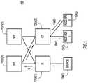
- An example network topology(hereinafter "network") is shown at reference numeral 100 in FIG. 1.
- the network 100comprises a plurality of router devices ("routers"), which are shown at reference numerals 102(a)(1), 102(a)(2), 102(b)(1) and 102(b)(2).
- the routersmay be switch devices ("switches"), and that these terms may be used interchangeably.
- the techniques hereinuse the term "router device” or "router.”
- Each of the routers in the network 100is arranged in a particular configuration based on its connectivity to other devices in the network 100.
- the routers 102(a)(1) and 102(a)(2)are arranged in a first configuration in the network 100 as “leaf' router devices
- the routers 102(b)(1) and 102(b)(2)are arranged in a second configuration in the network as “spine” router devices.
- the leaf router devicesmay be referred to as “leaf nodes” and the spine router devices may be referred to as "spine nodes.”
- the router 102(a)(1)is referred to hereinafter as “leaf 1" or “leaf node 1,” and the router 102(a)(2) is referred to hereinafter as “leaf 2" or “leaf node 2.”
- the router 102(b)(1)is referred to hereinafter as “spine 1” or “spine node 1”
- the router 102(b)(2)is referred to hereinafter as “spine 2" or “spine node 2.”
- the network 100may have any network of leaf nodes and spine nodes, and the topology shown in FIG. 1 is merely an example.
- the leaf nodes 102(a)(1) and 102(a)(2)may be arranged in the network 100 such that every leaf node is directly connected to every spine node.
- the spine 102(b)(1) and 102(b)(2)may be arranged in the network 100 such that every spine node is directly connected to every leaf node.
- the leaf nodesmay be fully-meshed with every spine node. This is also known as a Clos or Clos-like architecture. This arrangement, however, is only an example, and the leaf devices and spine devices may be arranged in other configurations.
- the designation of the routers 102(a)(1) and 102(a)(2) as leaf nodes and of the routers 102(b)(1) and 102(b)(2) as spine nodesindicates the device configuration within the network 100. All of the router devices may be the same router device type (e.g., Open Systems Interconnection (OSI) model layer 2 or layer 3 router devices, which may be referred to hereinafter as “layer 2 router devices” or “layer 3 router devices”).
- OSIOpen Systems Interconnection
- FIG. 1also shows a plurality of physical server devices ("physical devices") at reference numerals 104(1)-104(3).
- the physical devices 104(1)-104(3)may be, e.g., computers, laptops, tablets, mobile devices, etc. that are configured to send and receive communications to each other in the network 100 via one or more of the routers 104(a)(1), 104(a)(2), 104(b)(1) and 104(b)(2).
- physical device 104(1)is directly connected (or directly “attached") to leaf node 1
- physical devices 104(2) and 104(3)are directly connected to leaf node 2. It should be appreciated that any number of physical devices may be present in the network 100, and these physical devices may be directly or indirectly connected to one or more leaf nodes.
- the physical devices 104(1)-104(3)are configured to send and receive communications to each other in the network 100.
- Each of the physical devices 104(1)-104(3)may also host one or more virtual machines (not shown in FIG. 1 ), and each of these virtual machines may also be configured to send and receive communications to each other in the network 100.
- FIG. 1shows physical device 104(1) as a source physical device ("source”) and physical device 104(2) and 104(3) as receiver physical device (“receivers").
- Source 104(1)may also be referred to herein as the "source”
- receiver 104(2)may be referred to herein as “receiver 1”
- receiver 104(3)may be referred to herein as "receiver 2.”
- the source 104(1)is configured to send multicast communications that are destined for a multicast destination group address for which both the receiver 104(2) and the receiver 104(3) have shown interest.
- the packetwill indicate a multicast destination address or network associated with receiver 104(2) and 104(3).
- receiver 104(2)may be assigned or located in a Virtual Local Area Network (VLAN) 1
- receiver 104(3)may be assigned or located in VLAN 2.
- VLANVirtual Local Area Network
- the multicast packetis typically encapsulated with a layer 3 header.
- the leaf nodes 102(a)(1) and 102(a)(2)may typically operate as a layer 2/layer 3 router device, such that layer 2 communications are received from attached physical devices, encapsulated with a layer 3 header and forwarded to other router devices in the network 100.
- the routerdecapsulates the layer 3 header and sends the layer 2 packet to the destination physical device or devices.
- the host 104(1)is a layer 3 host and is sending Internet Protocol (IP) packets to leaf node 102(a)(1)
- the packetsare encapsulated in another packet that describes a virtual routing and forwarding ("VRF") context by specifying a segment identifier.
- VRFvirtual routing and forwarding
- the packetthen is decapsulated on leaf node 102(a)(2), which detects the destination VRF of the packet.
- the leaf node 102(a)(2)then sends the decapsulated packet to the receivers.
- VRFvirtual routing and forwarding
- the packetWhen the packet is a multicast packet, this differentiated and fragmented encapsulation among the routers may be especially problematic, since the packet may be forwarded to multiple router devices.
- the differentiated and fragmented encapsulationrequires multiple routers in a network to send multicast control packets to each other, which may result in network scalability problems.
- the leaf nodesmay have multicast receivers and senders either directly or indirectly connected to them.
- the techniques presented hereinprovide protocol independent core encapsulation techniques for multicast packets.
- the core encapsulation techniquesare related to a protocol for communications between the leaf nodes and the spine nodes in the network 100.
- the techniques hereinenable the core encapsulation by the router devices that are agnostic to other router-specific encapsulation techniques operated by routers in the core (interconnect between the spine and leaf nodes) of the network 100. Such techniques achieve optimized replication of multicast packets within the network 100 by minimizing the replication of these packets while supporting load balancing.
- the techniques described hereinenable the routers to use a segment identifier to define a distribution group of one or more routers in the network 100 for sending multicast packets.
- this segment identifierused to specify the VRF (i.e., a routing table instance or "routing table”) for the multicast packets.
- VLAN V'a transit VLAN in the network 100
- router devicescan encapsulate layer 2 packets agnostically for multicast transmission in the network 100.
- routing protocolsare enabled automatically on leaf nodes in a passive mode for fabric (or core) facing interfaces. With control protocol automatically enabled in passive mode on core facing interfaces, the absence of control plane packets due to the decoupling of control protocol and topology maintenance of the core allows a higher flexibility. This allows the fabric to scale to a large number of leaf devices as well as with a large number of tenants.
- receiver 104(2)belongs to VLAN 1 and receiver 104(3) belongs to VLAN 2.
- Receiver 104(2) and receiver 104(3)are directly attached to leaf 2.
- Leaf 2may send to receiver 104(2) and receiver 104(3) a message that is configured to solicit a response indicating a network assignment for receiver 104(2) and receiver 104(3).
- This messagemay be an Internet Group Management Protocol (IGMP) message or it may be any other message configured to solicit network assignment information.
- IGMPInternet Group Management Protocol
- receiver 104(2) and receiver 104(3)are each configured to send reports (e.g., via an IGMP response) to leaf 2 to advertise their respective allocations in VLAN 1 and VLAN 2.
- leaf 2Upon receiving the reports from receiver 104(2) and receiver 104(3), leaf 2 updates a route forwarding table (e.g., a VRF) to indicate the VLANs to which receiver 104(2) and 104(3) belong.
- the routing forwarding tablemay also be a Routing Information Base (RIB) table and/or a table that specifies Multicast Forwarding Information Base Distribution (MFDM) parameters.
- Leaf 2then associates (i.e., "maps") VLAN 1 and VLAN 2 to the transit VLAN V'. That is, in the VRF of leaf 2, VLAN 1 and VLAN 2 (and other VLANs associated with other physical devices attached to leaf 2) are mapped to a segment identifier associated with the transit VLAN V'.
- Leaf 2then sends this mapping information to all of the other routers in the network 100. Upon receiving this mapping information, the other routers in the network 100 store the mapping in their respective route forwarding tables. Thus, leaf 1, spine 1 and spine 2 are provided with information (e.g., the segment identifier) of the mapping of VLAN 1 and VLAN 2 to VLAN V'.
- informatione.g., the segment identifier
- VLAN V'defines a distribution group of router devices in the network 100 through which multicast packets may be sent.
- the distribution group defined by VLAN V'may include a subset of the routers in the network 100 to enable optimal distribution of a multicast packet with minimal packet replication.
- the distribution group of router devicesmay be established ad hoc or a priori by a network administrator, depending on, for example, network conditions (e.g., bandwidth, latency or other network characteristics).
- leaf 1modifies (e.g., encapsulates) the packet to include the segment identifier associated with VLAN V' (which has been mapped to VLAN 1 and VLAN 2 by leaf 2).
- the segment identifierenables the multicast packet to be sent as a layer 3 packet (e.g., a Protocol Independent Multicast (PIM) packet).
- PIMis enabled on every router in order to minimize network traffic, which is essential for supporting a high scale of multi-tenancy.
- Leaf 1then forwards the packet to the next hop router that is a part of the distribution group associated with VLAN V'.
- the multicast packetis forwarded through VLAN V', and ultimately reaches leaf 2.
- leaf 2analyzes (e.g., decapsulates) the packet to retrieve the segment identifier, and subsequently maps the segment identifier for VLAN V' to VLAN 1 and VLAN 2.
- leaf 2routes the multicast traffic in layer 2 to receiver 1 and receiver 2, which reside in VLAN 1 and VLAN 2, respectively.
- FIG. 2shows an example network 200 that includes the routers 102(a)(1), 102(a)(2), 102(b)(1) and 102(b)(2), described in FIG. 1 .
- FIG. 2also includes a border router device (“border router” or “border”) shown at reference numeral 106 and a rendezvous point (RP) router device (“RP router” or “RP”) shown at reference numeral 108.
- the border 106may be a border leaf (shown as "BL1" in FIG. 2 ).
- the border 106is connected to every spine in the network, and the RP 108 is connected only to the border 106.
- the RP 108is said to be remote to the other routers in the topology.
- the border 106 and the RP 108may be, for example, router devices that operate as layer 2/layer 3 router devices.
- Network 200also has physical devices shown at reference numerals 104(1) and 110.
- the physical device 104(1)is the source physical device (source) described in connection with FIG. 1 , above, and it is directly attached to leaf 1.
- the physical device 110is a physical device that is directly attached to the RP. Thus, the physical device 110 is also referred to as a remote physical device. In FIG. 2 , the physical device 110 is referred to as the "receiver 110."
- the source 104(1)is configured to send multicast communications destined for the receiver 110. It is assumed that leaf 1 has received the segment identifier for the transit VLAN (VLAN V') a priori from one or more routers or other network device before the source 104(1) sends communications to the receiver 110. For example, leaf 1 may have received the segment identifier for VLAN V' as described by the techniques in connection with FIG. 1 , above.
- the source 104(1)sends a layer 2 multicast packet to leaf 1.
- leaf 1Upon receiving the layer 2 multicast packet, leaf 1 creates state information for the packet (e.g., an (S, G) state, where "S" represents a source device and "G" represents a destination device), as shown at reference numeral 202.
- leaf 1sends a PIM packet (including the state information and the segment identifier for VLAN V') to RP 108.
- the PIM packetcomprises a core encapsulation (e.g., a layer 3 encapsulation) of the multicast packet (e.g., a layer 2 multicast packet) originating from the source 104(1).
- a core encapsulatione.g., a layer 3 encapsulation
- the techniques described hereinare not limited to layer 2 packets encapsulated in layer 3 packets.
- some embodimentsmay involve core encapsulation techniques comprising layer 3 encapsulation in layer 2 packets or other types of core encapsulation.
- leaf 1modifies the packet to include the segment identifier for the fabric VLAN V' in the destination address and forwards the packet to the routers in the network 200.
- the spine nodeswill initially drop this packet since these routers have not received state information or the segment identifier associated with the fabric VLAN V'.
- the RP 108at 208, sends the state information and segment identifier to the border 106.
- the border 106installs the state information and segment identifier in its route forwarding table (e.g., VRF), and distributes the state information and segment identifier (e.g., via a Border Gateway Protocol (BGP) message) to the other routers in the network 200, as shown at 210.
- route forwarding tablee.g., VRF
- BGPBorder Gateway Protocol
- the state information and segment identifiermay be distributed into a Multicast Routing Information Base (MRIB) table accessible by the spine nodes. After doing so, the spine nodes receive the state information and segment identifier associated with VLAN V'.
- MRIBMulticast Routing Information Base
- every router in the networkstores the state information and segment identifier for VLAN V' in its respective route forwarding table, and as a result, subsequent multicast packets originating from the source 104(1) can be forwarded in the network 200 using the transit fabric VLAN V'.
- FIG. 3shows an example network 300.
- the network 300is similar to the network 200 shown in FIG. 2 except that in FIG. 3 , the source 104(1) is remote and is directly attached to RP 108 instead of to leaf 1 and the receiver 110 is not remote, and instead is directly attached to leaf 1 instead of to the RP 108.
- the receiver 110sends, at reference numeral 302, an IGMP message to leaf 1 indicating network assignment information associated with the receiver 110 (e.g., the VLAN(s) to which receiver 110 is assigned).
- Leaf 1maps the network assignment information to the segment identifier information associated with the transit VLAN V', and at 304, sends the mapping information to the other routers in the network 300, except the RP 108 (since RP 108 is only connected to the border 106).
- the border 106upon receiving the mapping information, updates its route forwarding table at reference numeral 306.
- the border 106thus, has the layer 3 entry for the fabric VLAN V' (e.g., the segment identifier for VLAN V').
- the border 106sends this information (as a PIM communication) to RP 108, and the RP 108 stores this information in its route forwarding table.
- the source 104(1)is thus able to send layer 2 multicast packets via the RP 108, and the RP 108 is able to forward these packets in the network 300 using the segment identifier for VLAN V' for core encapsulation and forwarding.
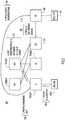
- FIG. 4shows an example ladder diagram 400 depicting operations for sending a multicast message in a network according to the techniques presented herein.
- the ladder diagram 400shows communications as described above in connection with FIG. 1 , though it should be appreciated that these techniques may be applicable to any of the embodiments described herein.
- leaf 2sends a message (e.g., an IGMP message) to a receiver.
- the receiver in FIG. 4may be either the receiver 104(2) ("receiver 1" in FIG. 1 ) or receiver 104(3) ("receiver 2" in FIG. 1 ).
- the receiver in FIG. 4is referred to simply as receiver 401.
- the IGMP message sent from leaf 2 to the receiver 401is a message that is configured to solicit a response indicating a network assignment for the receiver 401 (e.g., the VLAN to which receiver 401 belongs).
- the receiver 401responds to the IGMP message by sending to leaf 2 its state information, including its VLAN assignment.
- Leaf 2at 406, translates the state information to a segment identifier associated with the fabric VLAN V'.
- Leaf 2stores this information in its route forwarding table and, at 408, sends the segment identifier information to leaf 1.
- Leaf 1also stores the segment identifier information in its route forwarding table.
- the source 104(1)sends a subsequent layer 2 multicast packet with state information that indicates the receiver 401 as the destination.
- leaf 1receives the multicast packet and modifies the destination of the multicast packet to include the segment identifier information associated with fabric VLAN V' (previously obtained from leaf 2 in operation 408). For example, leaf 1 encapsulates the layer 2 multicast packet with a layer 3 segment identifier header. Leaf 1 then sends, at 414, the layer 3 encapsulated multicast packet with the segment identifier information to leaf 2.
- Leaf 2upon receiving the multicast packet, retrieves the state information (e.g., decapsulates the layer 3 segment identifier header in the packet) for the receiver 401 at 416, and at 418, leaf 2 sends the layer 2 multicast packet to the receiver 401.
- state informatione.g., decapsulates the layer 3 segment identifier header in the packet
- FIG. 5shows an example flow chart 500 depicting operations of a router device translating and forwarding a multicast message in a network.
- the router device in FIG. 5may be any of the routers described herein.
- a messageis sent to one or more physical devices.
- the messageis configured to solicit a response indicating a network assignment for each of the host devices.
- a response messageis received from each of the physical devices comprising network assignment information for each of the physical devices.
- the network assignment informationis translated, at 515, for each of the physical devices into a segment identifier, and at 520, the segment identifier is distributed to other router devices in the network.
- FIG. 6shows an example block diagram of a router device configured to translate and forward a multicast message.
- the router device in FIG. 6is referred to generally as router 600, though it should be appreciated that the router device 600 may be any of the router devices described herein.
- the router device 600comprises, among other components, a plurality of port units 602, a router application specific integrated circuit (ASIC) 604, a processor 606 and a memory 608.
- the ports 602receive communications (e.g., frames) from network devices and are configured to send communications to network devices. For example, the ports 602 send IGMP messages destined for physical devices and receive IGMP response messages from physical devices.
- the ports 602also send and receive mapping information including the segment identifier and other state information of physical network devices.
- the ports 602are coupled to the router ASIC 604.
- the router ASIC 604receives instructions from the processor 606 and forwards frames and/or packets to an appropriate one of the port units 602 for transmission to a destination network device.
- the router ASIC 604is coupled to the processor 606.
- the processor 606is, for example, a microprocessor or microcontroller that is configured to execute program logic instructions (i.e., software) for carrying out various operations and tasks of the switch device 600, as described above.
- the processor 606is configured to execute multicast packet translation and forwarding software 610 according to the techniques described above.
- the multicast translation and forwarding software 610also instructs the processor to update a route forwarding table 612 with segment identifier information, as described herein.
- the functions of the processor 606may be implemented by logic encoded in one or more tangible computer readable storage media or devices (e.g., storage devices compact discs, digital video discs, flash memory drives, etc. and embedded logic such as an application specific integrated circuit, digital signal processor instructions, software that is executed by a processor, etc.).
- tangible computer readable storage media or devicese.g., storage devices compact discs, digital video discs, flash memory drives, etc. and embedded logic such as an application specific integrated circuit, digital signal processor instructions, software that is executed by a processor, etc.
- the memory 608may comprise read only memory (ROM), random access memory (RAM), magnetic disk storage media devices, optical storage media devices, flash memory devices, electrical, optical, or other physical/tangible (non-transitory) memory storage devices.
- the memory 608stores software instructions for the multicast translation and forwarding logic 610.
- the memory 608also stores the route forwarding table 612.
- the memory 608may comprise one or more computer readable storage media (e.g., a memory storage device) encoded with software comprising computer executable instructions and when the software is executed (e.g., by the processor 606) it is operable to perform the operations described for the multicast packet translation and forwarding software 610.
- the multicast packet translation and forwarding software 610may take any of a variety of forms, so as to be encoded in one or more tangible computer readable memory media or storage device for execution, such as fixed logic or programmable logic (e.g., software/computer instructions executed by a processor), and the processor 606 may be an ASIC that comprises fixed digital logic, or a combination thereof.
- fixed logic or programmable logice.g., software/computer instructions executed by a processor
- the processor 606may be an ASIC that comprises fixed digital logic, or a combination thereof.
- the processor 606may be embodied by digital logic gates in a fixed or programmable digital logic integrated circuit, which digital logic gates are configured to perform the multicast packet translation and forwarding software 610.
- the multicast packet translation and forwarding software 610may be embodied in one or more computer readable storage media encoded with software comprising computer executable instructions and when the software is executed operable to perform the operations described hereinafter.
- the techniques described above in connection with all embodimentsmay be performed by one or more computer readable storage media that is encoded with software comprising computer executable instructions to perform the methods and steps described herein.
- the operations performed by the routers and physical devicesmay be performed by one or more computer or machine readable storage media (non-transitory) or device executed by a processor and comprising software, hardware or a combination of software and hardware to perform the techniques described herein.
- a methodcomprising: at a router device in a network, sending to one or more physical devices a message configured to solicit a response indicating a network assignment for each of the physical devices; receiving from each of the physical devices a response message comprising network assignment information for each of the physical devices; translating the network assignment information for each of the physical devices into a segment identifier; and distributing the segment identifier to other router devices in the network.
- a computer-readable storage mediais provided that is encoded with software comprising computer executable instructions and when the software is executed operable to: send to one or more physical devices in a network a message configured to solicit a response indicating a network assignment for each of the physical devices; receive from each of the physical devices a response message comprising network assignment information for each of the physical devices; translate the network assignment information for each of the physical devices into a segment identifier; and distribute the segment identifier to router devices in the network.
- an apparatuscomprising: a plurality of ports configured to receive and send messages in a network; and a processor coupled to the ports, and configured to: send to one or more physical devices a message configured to solicit a response indicating a network assignment for each of the physical devices; receive from each of the physical devices a response message comprising network assignment information for each of the physical devices; translate the network assignment information for each of the physical devices into a segment identifier; and distribute the segment identifier to router devices in the network.
Landscapes
- Engineering & Computer Science (AREA)
- Computer Networks & Wireless Communication (AREA)
- Signal Processing (AREA)
- Computer Security & Cryptography (AREA)
- Data Exchanges In Wide-Area Networks (AREA)
Description
- The present disclosure relates to optimizing multicast traffic routing in a network.
- Router devices in a network may be configured to manage network communications of one or more physical servers. The physical servers in the network may host one or more virtual machines, and thus, the router devices that manage the network communications of the physical servers may also manage communications of the one or more virtual machines. Typically, router devices may operate as Open Systems Interconnection (OSI)
layer 2/layer 3 router devices. In other words, a router device may send and receivelayer 2 communications to and from physical servers and may send and receivelayer 3 communications to and from other router devices. The physical servers may be configured to send and receive multicast messages to each other via one or more router devices.
Jin et al. "Virtualized Integrated Routing & Bridging with centralized control plane", 13 December 2012, proposes applying a centralized server to be the control plane for a combined L2&L3 solution, to provide better scalablility for the control plane.
ITU-T "Requirements and analysis for the management interface of Ethernet Passive Optical Networks (EPON)", Q.838.1, October 2004 describes a recommendation for the management of Ethernet Passive Optical Networks.US2007/0223493 describes a method and system for logical group endpoint discovery in a data communication network.
Jon Tate et al., "IBM j-type Data Center Networking Introduction", 7 May 2010, XP055147828, describes the expanded IBM j-type Data Center Networking choices. FIG. 1 shows an example network topology including router devices that are configured to translate and forward multicast messages received by a source physical server.FIG. 2 shows an example network topology including router devices that are configured to translate and forward multicast messages to a remote physical server.FIG. 3 shows an example network topology including router devices that are configured to receive multicast messages from the remotely located source physical server.FIG. 4 shows an example ladder diagram depicting operations for sending the multicast message in the network according to the techniques presented herein.FIG. 5 shows an example flow chart depicting operations of the router device in translating and forwarding multicast messages in the network.FIG. 6 shows an example block diagram of the router device that is configured to translate and forward the multicast message according to the techniques presented herein.- The invention is defined in the independent claims. Additional features of the invention are provided in the dependent claims. The embodiments and/or examples disclosed in the following description which are not covered by the appended claims are considered as not being part of the present invention.
- Techniques are presented herein for optimizing multicast traffic routing in a network. At a router device, a message is sent to one or more physical devices. The message is configured to solicit a response indicating a network assignment for each of the physical devices. A response message is received from each of the physical devices. The response message comprises network assignment information for each of the physical devices. For each of the physical devices, the network assignment information is translated into a segment identifier, wherein the segment identifier defines a distribution group for one or more router devices in the network. The segment identifier is distributed to other router devices in the network.
- The techniques presented herein involve optimizing multicast traffic in a network. In particular, the techniques presented herein enable core encapsulation that is agnostic to router-specific encapsulation techniques performed by routers in a network. Additionally, the techniques presented herein enable routing protocol automatically on nodes that are in a passive mode for core facing interfaces. Such techniques enable network scalability. An example network topology (hereinafter "network") is shown at
reference numeral 100 in FIG.
1. Thenetwork 100 comprises a plurality of router devices ("routers"), which are shown at reference numerals 102(a)(1), 102(a)(2), 102(b)(1) and 102(b)(2). It should be appreciated that the routers may be switch devices ("switches"), and that these terms may be used interchangeably. For simplicity, the techniques herein use the term "router device" or "router." - Each of the routers in the
network 100 is arranged in a particular configuration based on its connectivity to other devices in thenetwork 100. For example, the routers 102(a)(1) and 102(a)(2) are arranged in a first configuration in thenetwork 100 as "leaf' router devices, and the routers 102(b)(1) and 102(b)(2) are arranged in a second configuration in the network as "spine" router devices. The leaf router devices may be referred to as "leaf nodes" and the spine router devices may be referred to as "spine nodes." - The router 102(a)(1) is referred to hereinafter as "
leaf 1" or "leaf node 1," and the router 102(a)(2) is referred to hereinafter as "leaf 2" or "leaf node 2." Likewise, the router 102(b)(1) is referred to hereinafter as "spine 1" or "spine node 1," while the router 102(b)(2) is referred to hereinafter as "spine 2" or "spine node 2." It should be appreciated that thenetwork 100 may have any network of leaf nodes and spine nodes, and the topology shown inFIG. 1 is merely an example. - In one example, as shown in
FIG. 1 , the leaf nodes 102(a)(1) and 102(a)(2) may be arranged in thenetwork 100 such that every leaf node is directly connected to every spine node. Likewise, the spine 102(b)(1) and 102(b)(2) may be arranged in thenetwork 100 such that every spine node is directly connected to every leaf node. Thus, the leaf nodes may be fully-meshed with every spine node. This is also known as a Clos or Clos-like architecture. This arrangement, however, is only an example, and the leaf devices and spine devices may be arranged in other configurations. - The designation of the routers 102(a)(1) and 102(a)(2) as leaf nodes and of the routers 102(b)(1) and 102(b)(2) as spine nodes indicates the device configuration within the
network 100. All of the router devices may be the same router device type (e.g., Open Systems Interconnection (OSI)model layer 2 orlayer 3 router devices, which may be referred to hereinafter as "layer 2 router devices" or "layer 3 router devices"). FIG. 1 also shows a plurality of physical server devices ("physical devices") at reference numerals 104(1)-104(3). The physical devices 104(1)-104(3) may be, e.g., computers, laptops, tablets, mobile devices, etc. that are configured to send and receive communications to each other in thenetwork 100 via one or more of the routers 104(a)(1), 104(a)(2), 104(b)(1) and 104(b)(2). InFIG. 1 , physical device 104(1) is directly connected (or directly "attached") toleaf node 1, and physical devices 104(2) and 104(3) are directly connected toleaf node 2. It should be appreciated that any number of physical devices may be present in thenetwork 100, and these physical devices may be directly or indirectly connected to one or more leaf nodes.- As stated above, the physical devices 104(1)-104(3) are configured to send and receive communications to each other in the
network 100. Each of the physical devices 104(1)-104(3) may also host one or more virtual machines (not shown inFIG. 1 ), and each of these virtual machines may also be configured to send and receive communications to each other in thenetwork 100. For simplicity,FIG. 1 shows physical device 104(1) as a source physical device ("source") and physical device 104(2) and 104(3) as receiver physical device ("receivers"). Source 104(1) may also be referred to herein as the "source," while receiver 104(2) may be referred to herein as "receiver 1" and receiver 104(3) may be referred to herein as "receiver 2." - In one embodiment, the source 104(1) is configured to send multicast communications that are destined for a multicast destination group address for which both the receiver 104(2) and the receiver 104(3) have shown interest. Typically, when the source 104(1) sends a multicast communication, the packet will indicate a multicast destination address or network associated with receiver 104(2) and 104(3). In the example shown in
FIG. 1 , receiver 104(2) may be assigned or located in a Virtual Local Area Network (VLAN) 1 and receiver 104(3) may be assigned or located inVLAN 2. Thus, when the source 104(1) sends a multicast packet destined for both a multicast group that includes receiver 104(2) and receiver 104(3), the multicast packet will list or indicate a routing context for the packet in the form of a unique identifier. - In traditional network environments, when the source 104(1) sends a multicast packet in the
network 100, the multicast packet is typically encapsulated with alayer 3 header. For example, the leaf nodes 102(a)(1) and 102(a)(2) may typically operate as alayer 2/layer 3 router device, such thatlayer 2 communications are received from attached physical devices, encapsulated with alayer 3 header and forwarded to other router devices in thenetwork 100. Once the packet is received by the router that manages the destination device of the packet, the router decapsulates thelayer 3 header and sends thelayer 2 packet to the destination physical device or devices. Similarly, if the host 104(1) is alayer 3 host and is sending Internet Protocol (IP) packets to leaf node 102(a)(1), the packets are encapsulated in another packet that describes a virtual routing and forwarding ("VRF") context by specifying a segment identifier. The packet then is decapsulated on leaf node 102(a)(2), which detects the destination VRF of the packet. The leaf node 102(a)(2) then sends the decapsulated packet to the receivers. These traditional encapsulation techniques, however, are specific to the particular encapsulation protocols that are operated by the routers in thenetwork 100. In other words, each router may perform alayer 2 orlayer 3 encapsulation on locally originatedlayer 2 orlayer 3 packets according to different packet encapsulation protocols. - When the packet is a multicast packet, this differentiated and fragmented encapsulation among the routers may be especially problematic, since the packet may be forwarded to multiple router devices. In particular, the differentiated and fragmented encapsulation requires multiple routers in a network to send multicast control packets to each other, which may result in network scalability problems.
The leaf nodes may have multicast receivers and senders either directly or indirectly connected to them. The techniques presented herein provide protocol independent core encapsulation techniques for multicast packets. In one example, the core encapsulation techniques are related to a protocol for communications between the leaf nodes and the spine nodes in thenetwork 100. In other words, the techniques herein enable the core encapsulation by the router devices that are agnostic to other router-specific encapsulation techniques operated by routers in the core (interconnect between the spine and leaf nodes) of thenetwork 100. Such techniques achieve optimized replication of multicast packets within thenetwork 100 by minimizing the replication of these packets while supporting load balancing. In particular, the techniques described herein enable the routers to use a segment identifier to define a distribution group of one or more routers in thenetwork 100 for sending multicast packets. In one example, this segment identifier used to specify the VRF (i.e., a routing table instance or "routing table") for the multicast packets. An interface with the routing table instance, shown as V' inFIG. 1 , is created automatically and is associated with a transit VLAN in thenetwork 100, referred to herein as VLAN V'. Thus, by utilizing the segment identifier that is associated with transit VLAN V', router devices can encapsulatelayer 2 packets agnostically for multicast transmission in thenetwork 100. Additionally, routing protocols are enabled automatically on leaf nodes in a passive mode for fabric (or core) facing interfaces. With control protocol automatically enabled in passive mode on core facing interfaces, the absence of control plane packets due to the decoupling of control protocol and topology maintenance of the core allows a higher flexibility. This allows the fabric to scale to a large number of leaf devices as well as with a large number of tenants. - As shown in
FIG. 1 , receiver 104(2) belongs toVLAN 1 and receiver 104(3) belongs toVLAN 2. Receiver 104(2) and receiver 104(3) are directly attached toleaf 2.Leaf 2 may send to receiver 104(2) and receiver 104(3) a message that is configured to solicit a response indicating a network assignment for receiver 104(2) and receiver 104(3). This message may be an Internet Group Management Protocol (IGMP) message or it may be any other message configured to solicit network assignment information. In response, receiver 104(2) and receiver 104(3) are each configured to send reports (e.g., via an IGMP response) toleaf 2 to advertise their respective allocations inVLAN 1 andVLAN 2. Upon receiving the reports from receiver 104(2) and receiver 104(3),leaf 2 updates a route forwarding table (e.g., a VRF) to indicate the VLANs to which receiver 104(2) and 104(3) belong. The routing forwarding table may also be a Routing Information Base (RIB) table and/or a table that specifies Multicast Forwarding Information Base Distribution (MFDM) parameters.Leaf 2 then associates (i.e., "maps")VLAN 1 andVLAN 2 to the transit VLAN V'. That is, in the VRF ofleaf 2,VLAN 1 and VLAN 2 (and other VLANs associated with other physical devices attached to leaf 2) are mapped to a segment identifier associated with the transit VLAN V'.Leaf 2 then sends this mapping information to all of the other routers in thenetwork 100. Upon receiving this mapping information, the other routers in thenetwork 100 store the mapping in their respective route forwarding tables. Thus,leaf 1,spine 1 andspine 2 are provided with information (e.g., the segment identifier) of the mapping ofVLAN 1 andVLAN 2 to VLAN V'. - As stated above, VLAN V' defines a distribution group of router devices in the
network 100 through which multicast packets may be sent. For example, the distribution group defined by VLAN V' may include a subset of the routers in thenetwork 100 to enable optimal distribution of a multicast packet with minimal packet replication. The distribution group of router devices may be establishedad hoc ora priori by a network administrator, depending on, for example, network conditions (e.g., bandwidth, latency or other network characteristics). - In
FIG. 1 , when thesource 1 sends a multicast packet that is destined forreceiver 1 andreceiver 2, thesource 1 sends alayer 2 multicast packet that listsreceiver 1 andreceiver 2 as the destination address inVLAN 1 andVLAN 2 respectively. Upon receiving the multicast packet,leaf 1 modifies (e.g., encapsulates) the packet to include the segment identifier associated with VLAN V' (which has been mapped toVLAN 1 andVLAN 2 by leaf 2). The segment identifier enables the multicast packet to be sent as alayer 3 packet (e.g., a Protocol Independent Multicast (PIM) packet). In one example, PIM is enabled on every router in order to minimize network traffic, which is essential for supporting a high scale of multi-tenancy.Leaf 1 then forwards the packet to the next hop router that is a part of the distribution group associated with VLAN V'. The multicast packet is forwarded through VLAN V', and ultimately reachesleaf 2. Upon receiving the multicast packet,leaf 2 analyzes (e.g., decapsulates) the packet to retrieve the segment identifier, and subsequently maps the segment identifier for VLAN V' toVLAN 1 andVLAN 2. Upon such decapsulation,leaf 2 routes the multicast traffic inlayer 2 toreceiver 1 andreceiver 2, which reside inVLAN 1 andVLAN 2, respectively. - Reference is now made to
FIG. 2. FIG. 2 shows anexample network 200 that includes the routers 102(a)(1), 102(a)(2), 102(b)(1) and 102(b)(2), described inFIG. 1 .FIG. 2 also includes a border router device ("border router" or "border") shown atreference numeral 106 and a rendezvous point (RP) router device ("RP router" or "RP") shown atreference numeral 108. In one example, theborder 106 may be a border leaf (shown as "BL1" inFIG. 2 ). Theborder 106 is connected to every spine in the network, and theRP 108 is connected only to theborder 106. Thus, theRP 108 is said to be remote to the other routers in the topology. Theborder 106 and theRP 108 may be, for example, router devices that operate aslayer 2/layer 3 router devices.Network 200 also has physical devices shown at reference numerals 104(1) and 110. The physical device 104(1) is the source physical device (source) described in connection withFIG. 1 , above, and it is directly attached toleaf 1. Thephysical device 110 is a physical device that is directly attached to the RP. Thus, thephysical device 110 is also referred to as a remote physical device. InFIG. 2 , thephysical device 110 is referred to as the "receiver 110." - In
FIG. 2 , the source 104(1) is configured to send multicast communications destined for thereceiver 110. It is assumed thatleaf 1 has received the segment identifier for the transit VLAN (VLAN V')a priori from one or more routers or other network device before the source 104(1) sends communications to thereceiver 110. For example,leaf 1 may have received the segment identifier for VLAN V' as described by the techniques in connection withFIG. 1 , above. InFIG. 2 , the source 104(1) sends alayer 2 multicast packet toleaf 1. Upon receiving thelayer 2 multicast packet,leaf 1 creates state information for the packet (e.g., an (S, G) state, where "S" represents a source device and "G" represents a destination device), as shown atreference numeral 202. - As shown at
reference numeral 204,leaf 1 sends a PIM packet (including the state information and the segment identifier for VLAN V') toRP 108. The PIM packet comprises a core encapsulation (e.g., alayer 3 encapsulation) of the multicast packet (e.g., alayer 2 multicast packet) originating from the source 104(1). It should be appreciated, however, that the techniques described herein are not limited to layer 2 packets encapsulated inlayer 3 packets. In particular, some embodiments may involve core encapsulationtechniques comprising layer 3 encapsulation inlayer 2 packets or other types of core encapsulation. - For example, as shown at
reference numeral 206,leaf 1 modifies the packet to include the segment identifier for the fabric VLAN V' in the destination address and forwards the packet to the routers in thenetwork 200. The spine nodes, however, will initially drop this packet since these routers have not received state information or the segment identifier associated with the fabric VLAN V'. Meanwhile, theRP 108, at 208, sends the state information and segment identifier to theborder 106. Theborder 106 installs the state information and segment identifier in its route forwarding table (e.g., VRF), and distributes the state information and segment identifier (e.g., via a Border Gateway Protocol (BGP) message) to the other routers in thenetwork 200, as shown at 210. For example, the state information and segment identifier may be distributed into a Multicast Routing Information Base (MRIB) table accessible by the spine nodes. After doing so, the spine nodes receive the state information and segment identifier associated with VLAN V'. Thus, upon receiving this information, every router in the network stores the state information and segment identifier for VLAN V' in its respective route forwarding table, and as a result, subsequent multicast packets originating from the source 104(1) can be forwarded in thenetwork 200 using the transit fabric VLAN V'. - Reference is now made to
FIG. 3 , which shows an example network 300. The network 300 is similar to thenetwork 200 shown inFIG. 2 except that inFIG. 3 , the source 104(1) is remote and is directly attached toRP 108 instead of toleaf 1 and thereceiver 110 is not remote, and instead is directly attached toleaf 1 instead of to theRP 108. InFIG. 3 , thereceiver 110 sends, atreference numeral 302, an IGMP message toleaf 1 indicating network assignment information associated with the receiver 110 (e.g., the VLAN(s) to whichreceiver 110 is assigned).Leaf 1 maps the network assignment information to the segment identifier information associated with the transit VLAN V', and at 304, sends the mapping information to the other routers in the network 300, except the RP 108 (sinceRP 108 is only connected to the border 106). Theborder 106, upon receiving the mapping information, updates its route forwarding table atreference numeral 306. Theborder 106, thus, has thelayer 3 entry for the fabric VLAN V' (e.g., the segment identifier for VLAN V'). Atreference numeral 308, theborder 106 sends this information (as a PIM communication) toRP 108, and theRP 108 stores this information in its route forwarding table. As a result, the source 104(1) is thus able to sendlayer 2 multicast packets via theRP 108, and theRP 108 is able to forward these packets in the network 300 using the segment identifier for VLAN V' for core encapsulation and forwarding. - Reference is now made to
FIG. 4 , which shows an example ladder diagram 400 depicting operations for sending a multicast message in a network according to the techniques presented herein. For simplicity, the ladder diagram 400 shows communications as described above in connection withFIG. 1 , though it should be appreciated that these techniques may be applicable to any of the embodiments described herein. InFIG. 4 , atreference numeral 402,leaf 2 sends a message (e.g., an IGMP message) to a receiver. The receiver inFIG. 4 may be either the receiver 104(2) ("receiver 1" inFIG. 1 ) or receiver 104(3) ("receiver 2" inFIG. 1 ). For simplicity, the receiver inFIG. 4 is referred to simply asreceiver 401. The IGMP message sent fromleaf 2 to thereceiver 401 is a message that is configured to solicit a response indicating a network assignment for the receiver 401 (e.g., the VLAN to whichreceiver 401 belongs). Atreference numeral 404, thereceiver 401 responds to the IGMP message by sending toleaf 2 its state information, including its VLAN assignment.Leaf 2, at 406, translates the state information to a segment identifier associated with the fabric VLAN V'.Leaf 2 stores this information in its route forwarding table and, at 408, sends the segment identifier information toleaf 1.Leaf 1 also stores the segment identifier information in its route forwarding table. - At 410, the source 104(1) sends a
subsequent layer 2 multicast packet with state information that indicates thereceiver 401 as the destination. At 412,leaf 1 receives the multicast packet and modifies the destination of the multicast packet to include the segment identifier information associated with fabric VLAN V' (previously obtained fromleaf 2 in operation 408). For example,leaf 1 encapsulates thelayer 2 multicast packet with alayer 3 segment identifier header.Leaf 1 then sends, at 414, thelayer 3 encapsulated multicast packet with the segment identifier information toleaf 2.Leaf 2, upon receiving the multicast packet, retrieves the state information (e.g., decapsulates thelayer 3 segment identifier header in the packet) for thereceiver 401 at 416, and at 418,leaf 2 sends thelayer 2 multicast packet to thereceiver 401. - Reference is now made to
FIG. 5 , which shows anexample flow chart 500 depicting operations of a router device translating and forwarding a multicast message in a network. The router device inFIG. 5 may be any of the routers described herein. Atoperation 505, a message is sent to one or more physical devices. The message is configured to solicit a response indicating a network assignment for each of the host devices. At 510, a response message is received from each of the physical devices comprising network assignment information for each of the physical devices. The network assignment information is translated, at 515, for each of the physical devices into a segment identifier, and at 520, the segment identifier is distributed to other router devices in the network. - Reference is now made to
FIG. 6 , which shows an example block diagram of a router device configured to translate and forward a multicast message. The router device inFIG. 6 is referred to generally asrouter 600, though it should be appreciated that therouter device 600 may be any of the router devices described herein. Therouter device 600 comprises, among other components, a plurality ofport units 602, a router application specific integrated circuit (ASIC) 604, aprocessor 606 and amemory 608. Theports 602 receive communications (e.g., frames) from network devices and are configured to send communications to network devices. For example, theports 602 send IGMP messages destined for physical devices and receive IGMP response messages from physical devices. Theports 602 also send and receive mapping information including the segment identifier and other state information of physical network devices. Theports 602 are coupled to therouter ASIC 604. Therouter ASIC 604 receives instructions from theprocessor 606 and forwards frames and/or packets to an appropriate one of theport units 602 for transmission to a destination network device. Therouter ASIC 604 is coupled to theprocessor 606. Theprocessor 606 is, for example, a microprocessor or microcontroller that is configured to execute program logic instructions (i.e., software) for carrying out various operations and tasks of theswitch device 600, as described above. For example, theprocessor 606 is configured to execute multicast packet translation andforwarding software 610 according to the techniques described above. The multicast translation andforwarding software 610 also instructs the processor to update a route forwarding table 612 with segment identifier information, as described herein. The functions of theprocessor 606 may be implemented by logic encoded in one or more tangible computer readable storage media or devices (e.g., storage devices compact discs, digital video discs, flash memory drives, etc. and embedded logic such as an application specific integrated circuit, digital signal processor instructions, software that is executed by a processor, etc.). - The
memory 608 may comprise read only memory (ROM), random access memory (RAM), magnetic disk storage media devices, optical storage media devices, flash memory devices, electrical, optical, or other physical/tangible (non-transitory) memory storage devices. Thememory 608 stores software instructions for the multicast translation and forwardinglogic 610. Thememory 608 also stores the route forwarding table 612. Thus, in general, thememory 608 may comprise one or more computer readable storage media (e.g., a memory storage device) encoded with software comprising computer executable instructions and when the software is executed (e.g., by the processor 606) it is operable to perform the operations described for the multicast packet translation andforwarding software 610. - The multicast packet translation and
forwarding software 610 may take any of a variety of forms, so as to be encoded in one or more tangible computer readable memory media or storage device for execution, such as fixed logic or programmable logic (e.g., software/computer instructions executed by a processor), and theprocessor 606 may be an ASIC that comprises fixed digital logic, or a combination thereof. - For example, the
processor 606 may be embodied by digital logic gates in a fixed or programmable digital logic integrated circuit, which digital logic gates are configured to perform the multicast packet translation andforwarding software 610. In general, the multicast packet translation andforwarding software 610 may be embodied in one or more computer readable storage media encoded with software comprising computer executable instructions and when the software is executed operable to perform the operations described hereinafter. - It should be appreciated that the techniques described above in connection with all embodiments may be performed by one or more computer readable storage media that is encoded with software comprising computer executable instructions to perform the methods and steps described herein. For example, the operations performed by the routers and physical devices may be performed by one or more computer or machine readable storage media (non-transitory) or device executed by a processor and comprising software, hardware or a combination of software and hardware to perform the techniques described herein.
- In summary, a method is provided comprising: at a router device in a network, sending to one or more physical devices a message configured to solicit a response indicating a network assignment for each of the physical devices; receiving from each of the physical devices a response message comprising network assignment information for each of the physical devices; translating the network assignment information for each of the physical devices into a segment identifier; and distributing the segment identifier to other router devices in the network.
- In addition, a computer-readable storage media is provided that is encoded with software comprising computer executable instructions and when the software is executed operable to: send to one or more physical devices in a network a message configured to solicit a response indicating a network assignment for each of the physical devices; receive from each of the physical devices a response message comprising network assignment information for each of the physical devices; translate the network assignment information for each of the physical devices into a segment identifier; and distribute the segment identifier to router devices in the network.
- Furthermore, an apparatus is provided comprising: a plurality of ports configured to receive and send messages in a network; and a processor coupled to the ports, and configured to: send to one or more physical devices a message configured to solicit a response indicating a network assignment for each of the physical devices; receive from each of the physical devices a response message comprising network assignment information for each of the physical devices; translate the network assignment information for each of the physical devices into a segment identifier; and distribute the segment identifier to router devices in the network.
- The above description is intended by way of example only. Various modifications and structural changes may be made therein without departing from the scope of the concepts described herein and within the scope of the invention as defined in the appended claims.
Claims (11)
- A method (500) comprising:at a router device in a network, sending (505) to one or more physical devices a message configured to solicit a response indicating a network assignment for each of the physical devices;receiving (510) from each of the physical devices a response message comprising network assignment information for each of the physical devices;translating (515) the network assignment information for each of the physical devices into a segment identifier, wherein the segment identifier defines a distribution group for one or more router devices in the network; anddistributing (520) the segment identifier to other router devices in the network.
- The method of claim 1, wherein sending (505) comprises sending an Internet Group Management Protocol, IGMP, message to the physical devices.
- The method of claim 1, wherein receiving (510) comprises receiving from each of the physical devices a response message comprising information indicating a Virtual Local Area Network, VLAN, to which the physical devices are assigned.
- The method of claim 1, further comprising:at another router device in the network, receiving the segment identifier;receiving from a source physical device a packet that includes network assignment information for a destination physical device; andgenerating a modified packet from the packet, the modified packet including the segment identifier in a destination address.
- The method of claim 4, wherein receiving (510) the packet comprises receiving a multicast packet.
- The method of claim 4, further comprising sending the modified packet to router devices in the network that are part of the distribution group associated with the segment identifier.
- The method of claim 1, wherein translating (515) comprises translating the network assignment information into the segment identifier that identifies a Virtual Local Area Network, VLAN, of the one or more router devices in the network.
- The method of claim 1, wherein distributing (520) comprises distributing the segment identifier to other router devices in the network to enable Open Systems Interconnection layer 3 forwarding of multicast communications between the router devices in the network using the segment identifier.
- The method of claim 1, wherein distributing (520) comprises distributing the segment identifier to enable a control protocol at the other router devices in a passive mode.
- A computer-readable storage media encoded with software comprising computer executable instructions and when the software is executed operable to perform a method according to any preceding claim.
- An apparatus (600) comprising:a plurality of ports (602) configured to receive and send messages in a network; anda processor (606) coupled to the ports (602), and configured to perform a method according to any of claims 1 to 9.
Applications Claiming Priority (2)
| Application Number | Priority Date | Filing Date | Title |
|---|---|---|---|
| US14/080,202US9294292B2 (en) | 2013-11-14 | 2013-11-14 | Optimized multicast routing in a Clos-like network |
| PCT/US2014/063789WO2015073253A1 (en) | 2013-11-14 | 2014-11-04 | Optimized multicast routing in a clos-like network |
Publications (2)
| Publication Number | Publication Date |
|---|---|
| EP3069471A1 EP3069471A1 (en) | 2016-09-21 |
| EP3069471B1true EP3069471B1 (en) | 2018-10-10 |
Family
ID=51900541
Family Applications (1)
| Application Number | Title | Priority Date | Filing Date |
|---|---|---|---|
| EP14799092.3AActiveEP3069471B1 (en) | 2013-11-14 | 2014-11-04 | Optimized multicast routing in a clos-like network |
Country Status (4)
| Country | Link |
|---|---|
| US (2) | US9294292B2 (en) |
| EP (1) | EP3069471B1 (en) |
| CN (1) | CN105723654B (en) |
| WO (1) | WO2015073253A1 (en) |
Families Citing this family (11)
| Publication number | Priority date | Publication date | Assignee | Title |
|---|---|---|---|---|
| US9432204B2 (en) | 2013-08-24 | 2016-08-30 | Nicira, Inc. | Distributed multicast by endpoints |
| US9602385B2 (en)* | 2013-12-18 | 2017-03-21 | Nicira, Inc. | Connectivity segment selection |
| US9602392B2 (en) | 2013-12-18 | 2017-03-21 | Nicira, Inc. | Connectivity segment coloring |
| US9794079B2 (en) | 2014-03-31 | 2017-10-17 | Nicira, Inc. | Replicating broadcast, unknown-unicast, and multicast traffic in overlay logical networks bridged with physical networks |
| US10572509B2 (en) | 2015-07-27 | 2020-02-25 | Cisco Technology, Inc. | Scalable spine nodes with partial replication of routing information in a network environment |
| CN107306224B (en)* | 2016-04-19 | 2020-08-14 | 华为技术有限公司 | Routing path updating method, network management device and routing equipment |
| US10454698B1 (en)* | 2017-10-24 | 2019-10-22 | Cisco Technology, Inc. | Methods and apparatus for non-blocking IP multicast delivery of media data using spine and leaf architectures |
| CN111181855B (en)* | 2018-11-13 | 2021-06-04 | 北京华为数字技术有限公司 | A kind of multicast method and routing device |
| US10778457B1 (en) | 2019-06-18 | 2020-09-15 | Vmware, Inc. | Traffic replication in overlay networks spanning multiple sites |
| US12132656B2 (en)* | 2020-08-02 | 2024-10-29 | Mellanox Technologies, Ltd. | Stateful filtering systems and methods |
| US11784922B2 (en) | 2021-07-03 | 2023-10-10 | Vmware, Inc. | Scalable overlay multicast routing in multi-tier edge gateways |
Family Cites Families (20)
| Publication number | Priority date | Publication date | Assignee | Title |
|---|---|---|---|---|
| CN1980178A (en)* | 2005-12-03 | 2007-06-13 | 鸿富锦精密工业(深圳)有限公司 | Network apparatus and method for retransmitting multi-casting package |
| US7898982B2 (en)* | 2006-03-22 | 2011-03-01 | Alcatel Lucent | Logical group endpoint discovery for data communication network |
| US8259612B2 (en)* | 2006-06-09 | 2012-09-04 | Cisco Technologies, Inc. | Method of routing multicast traffic |
| US8539065B2 (en) | 2006-07-26 | 2013-09-17 | Cisco Technology, Inc. | Method and apparatus for providing access to real time control protocol information for improved media quality control |
| JP2008079175A (en)* | 2006-09-25 | 2008-04-03 | Alaxala Networks Corp | Frame transfer system |
| WO2010057198A1 (en) | 2008-11-17 | 2010-05-20 | Starent Networks, Corp | Dynamic load balancing in a communication network |
| US8467403B2 (en)* | 2010-04-29 | 2013-06-18 | Cisco Technology, Inc. | Coordinated updating of forwarding information bases in a multistage packet switching device |
| JP2011243112A (en)* | 2010-05-20 | 2011-12-01 | Hitachi Ltd | System management method and management device |
| EP2730060A4 (en)* | 2011-07-06 | 2014-12-03 | Ericsson Telefon Ab L M | Dynamic updating of a label switched path |
| CN103139037B (en)* | 2011-11-30 | 2016-05-18 | 国际商业机器公司 | For realizing the method and apparatus of VLAN flexibly |
| US10050824B2 (en)* | 2012-01-20 | 2018-08-14 | Arris Enterprises Llc | Managing a cluster of switches using multiple controllers |
| US9288067B2 (en)* | 2012-03-20 | 2016-03-15 | Cisco Technology, Inc. | Adjacency server for virtual private networks |
| US8751650B2 (en)* | 2012-05-10 | 2014-06-10 | Cisco Technology, Inc. | Method and apparatus for supporting access control lists in a multi-tenant environment |
| US9253140B2 (en)* | 2012-11-20 | 2016-02-02 | Cisco Technology, Inc. | System and method for optimizing within subnet communication in a network environment |
| FR3001849B1 (en)* | 2013-02-05 | 2016-06-24 | Byo Networks | METHOD FOR ROUTING DATA, COMPUTER PROGRAM, NETWORK CONTROLLER AND ASSOCIATED NETWORKS |
| US9137119B2 (en)* | 2013-03-07 | 2015-09-15 | Cisco Technology, Inc. | Efficient handling of multi-destination traffic in an internet protocol fabric data center |
| US9432204B2 (en)* | 2013-08-24 | 2016-08-30 | Nicira, Inc. | Distributed multicast by endpoints |
| US9565105B2 (en)* | 2013-09-04 | 2017-02-07 | Cisco Technology, Inc. | Implementation of virtual extensible local area network (VXLAN) in top-of-rack switches in a network environment |
| US20150085862A1 (en)* | 2013-09-24 | 2015-03-26 | Hangzhou H3C Technologies Co., Ltd. | Forwarding Multicast Data Packets |
| US10044612B2 (en)* | 2013-11-06 | 2018-08-07 | Citrix Systems, Inc. | Systems and methods for port allocation |
- 2013
- 2013-11-14USUS14/080,202patent/US9294292B2/enactiveActive
- 2014
- 2014-11-04EPEP14799092.3Apatent/EP3069471B1/enactiveActive
- 2014-11-04WOPCT/US2014/063789patent/WO2015073253A1/enactiveApplication Filing
- 2014-11-04CNCN201480062482.1Apatent/CN105723654B/enactiveActive
- 2016
- 2016-02-10USUS15/040,090patent/US9504016B2/enactiveActive
Also Published As
| Publication number | Publication date |
|---|---|
| EP3069471A1 (en) | 2016-09-21 |
| WO2015073253A1 (en) | 2015-05-21 |
| US9294292B2 (en) | 2016-03-22 |
| US9504016B2 (en) | 2016-11-22 |
| US20160157210A1 (en) | 2016-06-02 |
| CN105723654B (en) | 2019-07-12 |
| US20150131655A1 (en) | 2015-05-14 |
| CN105723654A (en) | 2016-06-29 |
Similar Documents
| Publication | Publication Date | Title |
|---|---|---|
| EP3069471B1 (en) | Optimized multicast routing in a clos-like network | |
| US11398921B2 (en) | SDN facilitated multicast in data center | |
| US11240065B2 (en) | NSH encapsulation for traffic steering | |
| US11374857B2 (en) | Network device management method and apparatus, and system for indicating a network device to perform management operation | |
| US9621373B2 (en) | Proxy address resolution protocol on a controller device | |
| CN106936777B (en) | Cloud computing distributed network implementation method and system based on OpenFlow | |
| EP3219057B1 (en) | Optimized inter-vrf (virtual routing and forwarding ) route leaking in network overlay based environments | |
| EP2874359B1 (en) | Extended ethernet fabric switches | |
| US9800497B2 (en) | Operations, administration and management (OAM) in overlay data center environments | |
| CN104283756B (en) | A kind of method and apparatus for realizing distributed multi-tenant virtual network | |
| US10193707B2 (en) | Packet transmission method and apparatus | |
| EP2843906B1 (en) | Method, apparatus, and system for data transmission | |
| US20140233569A1 (en) | Distributed Gateway in Virtual Overlay Networks | |
| US20160149795A1 (en) | Overlay network-based original packet flow mapping apparatus and method therefor | |
| CN107040441B (en) | Cross-data-center data transmission method, device and system | |
| CN108964940A (en) | Message method and device, storage medium | |
| US9438475B1 (en) | Supporting relay functionality with a distributed layer 3 gateway | |
| CN102710510B (en) | Information processing method, apparatus and system | |
| US9548887B2 (en) | Proactive creation of multicast state in an overlay transport network to achieve fast convergence on failover |
Legal Events
| Date | Code | Title | Description |
|---|---|---|---|
| PUAI | Public reference made under article 153(3) epc to a published international application that has entered the european phase | Free format text:ORIGINAL CODE: 0009012 | |
| 17P | Request for examination filed | Effective date:20160415 | |
| AK | Designated contracting states | Kind code of ref document:A1 Designated state(s):AL AT BE BG CH CY CZ DE DK EE ES FI FR GB GR HR HU IE IS IT LI LT LU LV MC MK MT NL NO PL PT RO RS SE SI SK SM TR | |
| AX | Request for extension of the european patent | Extension state:BA ME | |
| DAX | Request for extension of the european patent (deleted) | ||
| 17Q | First examination report despatched | Effective date:20170904 | |
| GRAP | Despatch of communication of intention to grant a patent | Free format text:ORIGINAL CODE: EPIDOSNIGR1 | |
| INTG | Intention to grant announced | Effective date:20180502 | |
| GRAS | Grant fee paid | Free format text:ORIGINAL CODE: EPIDOSNIGR3 | |
| GRAA | (expected) grant | Free format text:ORIGINAL CODE: 0009210 | |
| AK | Designated contracting states | Kind code of ref document:B1 Designated state(s):AL AT BE BG CH CY CZ DE DK EE ES FI FR GB GR HR HU IE IS IT LI LT LU LV MC MK MT NL NO PL PT RO RS SE SI SK SM TR | |
| REG | Reference to a national code | Ref country code:GB Ref legal event code:FG4D | |
| REG | Reference to a national code | Ref country code:CH Ref legal event code:EP Ref country code:AT Ref legal event code:REF Ref document number:1052520 Country of ref document:AT Kind code of ref document:T Effective date:20181015 | |
| REG | Reference to a national code | Ref country code:IE Ref legal event code:FG4D | |
| REG | Reference to a national code | Ref country code:DE Ref legal event code:R096 Ref document number:602014033927 Country of ref document:DE | |
| REG | Reference to a national code | Ref country code:NL Ref legal event code:MP Effective date:20181010 | |
| REG | Reference to a national code | Ref country code:LT Ref legal event code:MG4D | |
| REG | Reference to a national code | Ref country code:AT Ref legal event code:MK05 Ref document number:1052520 Country of ref document:AT Kind code of ref document:T Effective date:20181010 | |
| PG25 | Lapsed in a contracting state [announced via postgrant information from national office to epo] | Ref country code:NL Free format text:LAPSE BECAUSE OF FAILURE TO SUBMIT A TRANSLATION OF THE DESCRIPTION OR TO PAY THE FEE WITHIN THE PRESCRIBED TIME-LIMIT Effective date:20181010 | |
| PG25 | Lapsed in a contracting state [announced via postgrant information from national office to epo] | Ref country code:LV Free format text:LAPSE BECAUSE OF FAILURE TO SUBMIT A TRANSLATION OF THE DESCRIPTION OR TO PAY THE FEE WITHIN THE PRESCRIBED TIME-LIMIT Effective date:20181010 Ref country code:AT Free format text:LAPSE BECAUSE OF FAILURE TO SUBMIT A TRANSLATION OF THE DESCRIPTION OR TO PAY THE FEE WITHIN THE PRESCRIBED TIME-LIMIT Effective date:20181010 Ref country code:NO Free format text:LAPSE BECAUSE OF FAILURE TO SUBMIT A TRANSLATION OF THE DESCRIPTION OR TO PAY THE FEE WITHIN THE PRESCRIBED TIME-LIMIT Effective date:20190110 Ref country code:LT Free format text:LAPSE BECAUSE OF FAILURE TO SUBMIT A TRANSLATION OF THE DESCRIPTION OR TO PAY THE FEE WITHIN THE PRESCRIBED TIME-LIMIT Effective date:20181010 Ref country code:ES Free format text:LAPSE BECAUSE OF FAILURE TO SUBMIT A TRANSLATION OF THE DESCRIPTION OR TO PAY THE FEE WITHIN THE PRESCRIBED TIME-LIMIT Effective date:20181010 Ref country code:HR Free format text:LAPSE BECAUSE OF FAILURE TO SUBMIT A TRANSLATION OF THE DESCRIPTION OR TO PAY THE FEE WITHIN THE PRESCRIBED TIME-LIMIT Effective date:20181010 Ref country code:PL Free format text:LAPSE BECAUSE OF FAILURE TO SUBMIT A TRANSLATION OF THE DESCRIPTION OR TO PAY THE FEE WITHIN THE PRESCRIBED TIME-LIMIT Effective date:20181010 Ref country code:BG Free format text:LAPSE BECAUSE OF FAILURE TO SUBMIT A TRANSLATION OF THE DESCRIPTION OR TO PAY THE FEE WITHIN THE PRESCRIBED TIME-LIMIT Effective date:20190110 Ref country code:FI Free format text:LAPSE BECAUSE OF FAILURE TO SUBMIT A TRANSLATION OF THE DESCRIPTION OR TO PAY THE FEE WITHIN THE PRESCRIBED TIME-LIMIT Effective date:20181010 Ref country code:IS Free format text:LAPSE BECAUSE OF FAILURE TO SUBMIT A TRANSLATION OF THE DESCRIPTION OR TO PAY THE FEE WITHIN THE PRESCRIBED TIME-LIMIT Effective date:20190210 | |
| PG25 | Lapsed in a contracting state [announced via postgrant information from national office to epo] | Ref country code:GR Free format text:LAPSE BECAUSE OF FAILURE TO SUBMIT A TRANSLATION OF THE DESCRIPTION OR TO PAY THE FEE WITHIN THE PRESCRIBED TIME-LIMIT Effective date:20190111 Ref country code:SE Free format text:LAPSE BECAUSE OF FAILURE TO SUBMIT A TRANSLATION OF THE DESCRIPTION OR TO PAY THE FEE WITHIN THE PRESCRIBED TIME-LIMIT Effective date:20181010 Ref country code:RS Free format text:LAPSE BECAUSE OF FAILURE TO SUBMIT A TRANSLATION OF THE DESCRIPTION OR TO PAY THE FEE WITHIN THE PRESCRIBED TIME-LIMIT Effective date:20181010 Ref country code:AL Free format text:LAPSE BECAUSE OF FAILURE TO SUBMIT A TRANSLATION OF THE DESCRIPTION OR TO PAY THE FEE WITHIN THE PRESCRIBED TIME-LIMIT Effective date:20181010 Ref country code:PT Free format text:LAPSE BECAUSE OF FAILURE TO SUBMIT A TRANSLATION OF THE DESCRIPTION OR TO PAY THE FEE WITHIN THE PRESCRIBED TIME-LIMIT Effective date:20190210 | |
| REG | Reference to a national code | Ref country code:CH Ref legal event code:PL | |
| REG | Reference to a national code | Ref country code:DE Ref legal event code:R097 Ref document number:602014033927 Country of ref document:DE | |
| PG25 | Lapsed in a contracting state [announced via postgrant information from national office to epo] | Ref country code:DK Free format text:LAPSE BECAUSE OF FAILURE TO SUBMIT A TRANSLATION OF THE DESCRIPTION OR TO PAY THE FEE WITHIN THE PRESCRIBED TIME-LIMIT Effective date:20181010 Ref country code:IT Free format text:LAPSE BECAUSE OF FAILURE TO SUBMIT A TRANSLATION OF THE DESCRIPTION OR TO PAY THE FEE WITHIN THE PRESCRIBED TIME-LIMIT Effective date:20181010 Ref country code:CZ Free format text:LAPSE BECAUSE OF FAILURE TO SUBMIT A TRANSLATION OF THE DESCRIPTION OR TO PAY THE FEE WITHIN THE PRESCRIBED TIME-LIMIT Effective date:20181010 Ref country code:LU Free format text:LAPSE BECAUSE OF NON-PAYMENT OF DUE FEES Effective date:20181104 | |
| PLBE | No opposition filed within time limit | Free format text:ORIGINAL CODE: 0009261 | |
| STAA | Information on the status of an ep patent application or granted ep patent | Free format text:STATUS: NO OPPOSITION FILED WITHIN TIME LIMIT | |
| REG | Reference to a national code | Ref country code:BE Ref legal event code:MM Effective date:20181130 | |
| REG | Reference to a national code | Ref country code:IE Ref legal event code:MM4A | |
| PG25 | Lapsed in a contracting state [announced via postgrant information from national office to epo] | Ref country code:RO Free format text:LAPSE BECAUSE OF FAILURE TO SUBMIT A TRANSLATION OF THE DESCRIPTION OR TO PAY THE FEE WITHIN THE PRESCRIBED TIME-LIMIT Effective date:20181010 Ref country code:LI Free format text:LAPSE BECAUSE OF NON-PAYMENT OF DUE FEES Effective date:20181130 Ref country code:MC Free format text:LAPSE BECAUSE OF FAILURE TO SUBMIT A TRANSLATION OF THE DESCRIPTION OR TO PAY THE FEE WITHIN THE PRESCRIBED TIME-LIMIT Effective date:20181010 Ref country code:SK Free format text:LAPSE BECAUSE OF FAILURE TO SUBMIT A TRANSLATION OF THE DESCRIPTION OR TO PAY THE FEE WITHIN THE PRESCRIBED TIME-LIMIT Effective date:20181010 Ref country code:CH Free format text:LAPSE BECAUSE OF NON-PAYMENT OF DUE FEES Effective date:20181130 Ref country code:EE Free format text:LAPSE BECAUSE OF FAILURE TO SUBMIT A TRANSLATION OF THE DESCRIPTION OR TO PAY THE FEE WITHIN THE PRESCRIBED TIME-LIMIT Effective date:20181010 Ref country code:SM Free format text:LAPSE BECAUSE OF FAILURE TO SUBMIT A TRANSLATION OF THE DESCRIPTION OR TO PAY THE FEE WITHIN THE PRESCRIBED TIME-LIMIT Effective date:20181010 | |
| 26N | No opposition filed | Effective date:20190711 | |
| PG25 | Lapsed in a contracting state [announced via postgrant information from national office to epo] | Ref country code:SI Free format text:LAPSE BECAUSE OF FAILURE TO SUBMIT A TRANSLATION OF THE DESCRIPTION OR TO PAY THE FEE WITHIN THE PRESCRIBED TIME-LIMIT Effective date:20181010 Ref country code:IE Free format text:LAPSE BECAUSE OF NON-PAYMENT OF DUE FEES Effective date:20181104 | |
| PG25 | Lapsed in a contracting state [announced via postgrant information from national office to epo] | Ref country code:BE Free format text:LAPSE BECAUSE OF NON-PAYMENT OF DUE FEES Effective date:20181130 | |
| PG25 | Lapsed in a contracting state [announced via postgrant information from national office to epo] | Ref country code:MT Free format text:LAPSE BECAUSE OF NON-PAYMENT OF DUE FEES Effective date:20181104 | |
| PG25 | Lapsed in a contracting state [announced via postgrant information from national office to epo] | Ref country code:TR Free format text:LAPSE BECAUSE OF FAILURE TO SUBMIT A TRANSLATION OF THE DESCRIPTION OR TO PAY THE FEE WITHIN THE PRESCRIBED TIME-LIMIT Effective date:20181010 | |
| PG25 | Lapsed in a contracting state [announced via postgrant information from national office to epo] | Ref country code:CY Free format text:LAPSE BECAUSE OF FAILURE TO SUBMIT A TRANSLATION OF THE DESCRIPTION OR TO PAY THE FEE WITHIN THE PRESCRIBED TIME-LIMIT Effective date:20181010 Ref country code:HU Free format text:LAPSE BECAUSE OF FAILURE TO SUBMIT A TRANSLATION OF THE DESCRIPTION OR TO PAY THE FEE WITHIN THE PRESCRIBED TIME-LIMIT; INVALID AB INITIO Effective date:20141104 Ref country code:MK Free format text:LAPSE BECAUSE OF NON-PAYMENT OF DUE FEES Effective date:20181010 | |
| P01 | Opt-out of the competence of the unified patent court (upc) registered | Effective date:20230525 | |
| PGFP | Annual fee paid to national office [announced via postgrant information from national office to epo] | Ref country code:DE Payment date:20241024 Year of fee payment:11 | |
| PGFP | Annual fee paid to national office [announced via postgrant information from national office to epo] | Ref country code:GB Payment date:20241112 Year of fee payment:11 | |
| PGFP | Annual fee paid to national office [announced via postgrant information from national office to epo] | Ref country code:FR Payment date:20241127 Year of fee payment:11 |